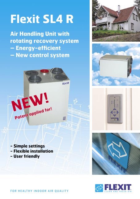
Flexit SL4 R
Flexit SL4 R
Flexit SL4 R

You also want an ePaper? Increase the reach of your titles
YUMPU automatically turns print PDFs into web optimized ePapers that Google loves.
<strong>Flexit</strong> <strong>SL4</strong> R<br />
Air Handling Unit with<br />
rotating recovery system<br />
– Energy-efficient<br />
– New control system<br />
NEW!<br />
Patent applied for!<br />
- Simple settings<br />
- Flexible installation<br />
- User friendly<br />
F O R H E A LT H Y I N D O O R A I R Q U A L I T Y
<strong>Flexit</strong> <strong>SL4</strong> R<br />
air handling unit with rotor technology<br />
- Energy-efficient<br />
- Flexible installation<br />
- User friendly<br />
<strong>Flexit</strong>’s new ventilation unit has a number of important<br />
product advantages and meets the new stricter<br />
energy effi ciency requirements being introduced in<br />
various European countries. The unit has a unique<br />
design (patent applied for) which gives great fl exibility<br />
of installation in terms of positioning of ducts and<br />
location of the unit.<br />
<strong>Flexit</strong> <strong>SL4</strong> R has a rotating recovery system that<br />
ensures high recovery and simple installation.<br />
The unit is compact and has small physical dimensions<br />
(height 700 mm, width 598 mm and depth 450 mm).<br />
<strong>Flexit</strong> <strong>SL4</strong> R is suitable for detached houses, smaller<br />
homes and fl ats and smaller offi ces. The unit can be<br />
connected to an external cooker hood.<br />
Energy savings and effi ciency<br />
A balanced ventilation unit with rotating recovery<br />
system lowers the cost of heating up ventilation air<br />
by up to 80% compared to an extract unit.<br />
Example of savings in an ordinary semi-bungalow:<br />
Heating requirement with central extraction:<br />
approx. 10,600 kWh per year.<br />
Heating requirement with balanced ventilation with<br />
80% heat recovery: approx. 2120 kWh per year.<br />
Saving: 8480 kWh per year, multiplied by energy<br />
cost for heating.<br />
3<br />
<br />
<br />
<br />
<br />
<br />
<br />
<br />
<br />
<br />
With a balanced ventilation unit with<br />
heat recovery you save up to 80%<br />
of the cost of heating the ventilation<br />
air compared to an extraction unit.
Optimum ventilation with<br />
<strong>Flexit</strong> <strong>SL4</strong> R<br />
Clean, fresh air – all year round<br />
The rotor unit offers stable operation throughout the<br />
year. The rotor technology copes effortlessly with<br />
icing and refreezing. This is particularly important in<br />
the Nordic countries with their cold climatic conditions.<br />
High efficiency – energy savings<br />
The rotor unit has a high efficiency and recovers up<br />
to 80% of the heat from the air extracted from the<br />
home. The high efficiency ensures that a high proportion<br />
of the energy used for heating the ventilation air<br />
is recovered while still providing the desired ventilation<br />
in the home – even in the cold season.<br />
Energy consumption<br />
<strong>Flexit</strong> <strong>SL4</strong> R can be supplied with standard fans (AC)<br />
and low-energy fans (EC fans). EC fans have extra<br />
low energy consumption and ensure that the units<br />
are in readiness for future strict energy consumption<br />
requirements which will particularly focus on SFP<br />
(Specific Fan Power). The SFP value informs how<br />
efficiently a fan is able to transport the air.<br />
Extra heating required only in severe cold<br />
The rotor unit has a high efficiency and meets all the<br />
heating requirements for the ventilation air for most<br />
of the year. The heating batteries are dimensioned to<br />
cover heating requirements for ventilation air all year<br />
round, even when outside temperatures are very low.<br />
There is a choice between electric or water-based<br />
supplementary heating. For units with water-based<br />
supplementary heating, a water battery is provided<br />
for external installation in the duct.<br />
Automatic summer operation<br />
The rotor unit has an electronic control that automatically<br />
switches the recovery function off/on in<br />
accordance with the outside temperature. This gives<br />
much simpler operation than, say, a plate heat<br />
exchanger, which involves use of a summer cassette.<br />
4<br />
Outdoor air<br />
Exhaust air<br />
Cleaning sector<br />
Simpler installation without a drainage<br />
outlet<br />
The rotor technology does not require condensation<br />
drainage. The moisture in the extract air follows the<br />
air out of the house in the exhaust duct. As there is no<br />
need for a drainage outlet, this means simpler installation<br />
and lower installation costs, plus great freedom<br />
when it comes to locating the unit.<br />
Area of use<br />
The unit is particularly well suited to flats and small<br />
detached houses. The unit can be located in many<br />
different areas, for example in an outhouse, utility<br />
room, passage or loft. The unit can be installed vertically<br />
as a cabinet model or horizontally, for example<br />
in a loft.<br />
l/s 0 20 40 60 80<br />
400<br />
300<br />
200<br />
100<br />
Pa 0<br />
230V<br />
190V<br />
170V<br />
150V<br />
120V<br />
105V<br />
85V<br />
60V<br />
60V<br />
Extract air<br />
Basic sketch of rotor operation<br />
Heat from the extract air passes through the rotor<br />
material to the supply air feeding the home.<br />
To prevent contaminated air entering the supply air,<br />
the rotor has a cleaning sector.<br />
85V<br />
Supply<br />
air<br />
Designed for<br />
modern homes<br />
<strong>Flexit</strong> <strong>SL4</strong> R is in white<br />
lacquer with rounded<br />
front door. The unit has<br />
been constructed for<br />
installation in a utility<br />
room, outhouse, technical<br />
room or loft.<br />
150V<br />
190<br />
170V<br />
70dB(A<br />
60dB(A) 65dB(A)<br />
120V<br />
105V
Flexible installation<br />
The design of the unit permits many different vari-<br />
ations of duct arrangement or locations in a home.<br />
The unit is designed for installation in utility rooms,<br />
outhouses, lofts or other suitable rooms. The unit can<br />
be supplied in left or right versions (exhaust nozzle<br />
to the left or right) depending on what is most con-<br />
venient for duct location. The advantage of rotor<br />
technology is that no condensation water is formed<br />
and connection to a drainage outlet is unnecessary.<br />
In wet rooms the unit must be located in zone 3 (mini-<br />
mum 0.6m from the edge of the bath and 1.2m from<br />
the shower head).<br />
Wall installation as a cabinet model<br />
<strong>Flexit</strong> <strong>SL4</strong> R is ideal for wall installation as a cabinet<br />
model. For example the unit can be mounted in a wet<br />
room over a hot water heater or in conjunction with a<br />
wall cupboard. (Fig. 1).<br />
5<br />
Loft installation<br />
<strong>Flexit</strong> <strong>SL4</strong> R has a chassis insulated for condensation<br />
and heat loss, which means that it can be installed in<br />
cold lofts. (Figs. 2a and b)<br />
NB Mounting according to fig. 2a requires adjusting<br />
the nailing strip for hanging (see installation instruc-<br />
tions).<br />
Mounting according to fig. 2b requires the use of the<br />
prescribed underlay (see installation instructions) to<br />
avoid vibration noise.<br />
Fig. 2a<br />
Fig. 1 Fig. 2b<br />
Additional floor panel<br />
Yellow<br />
Additional insulation<br />
Insulation.
Flexible duct connection<br />
The duct connections can be installed in different<br />
combinations, depending on what is most suitable in<br />
relation to the building:<br />
• Traditional top connection of ducts (Fig. 1, page 5).<br />
• Outdoor air and extract air ducts on one side and<br />
supply air and exhaust air ducts on the other side<br />
(Fig. 3)<br />
• All duct connections on one side of the unit (Fig. 4)<br />
• The extract duct can be connected to both of the<br />
short sides in the case of shorter ducts (Fig. 5).<br />
• All duct connections on one side of the unit plus an<br />
extra extract duct on the other side (Fig. 5).<br />
• Extract air, supply air and exhaust air ducts on one<br />
side and outdoor air on the other side of the unit<br />
(Fig. 6)<br />
• The outdoor air duct and the extract duct can if<br />
desired easily be joined to one of the short sides of<br />
the unit (top and bottom).<br />
External connection of a kitchen hood<br />
The unit can be connected to an external kitchen<br />
hood. A separate duct connection provided as standard<br />
on the unit is used for the external kitchen hood.<br />
During cooking, the extract air is led from the cooker<br />
hood round the rotary heat exchanger. The cooker<br />
hood is supplied separately and is installed on site.<br />
There is a choice between slimline models, built-in<br />
hoods and ventilator cabinet models. Ask for information<br />
on our cooker hoods.<br />
The Building Regulations recommend permanent<br />
ventilation in the kitchen. The appropriate ventilator<br />
should be located in the ceiling or wall. The louvres in<br />
the cookerhood must close when not in use.<br />
Explanation of symbols<br />
External<br />
connection of<br />
cooker hood<br />
6<br />
Fig. 3<br />
Fig. 4<br />
Fig. 5<br />
Fig. 6
Product Description<br />
<strong>Flexit</strong> <strong>SL4</strong> R with rotating<br />
recovery system.<br />
System description<br />
The unit is designed to provide optimal air com-<br />
fort combined with low energy consumption in the<br />
home. The heated used indoor air is sucked out via<br />
the extract valves in the kitchen and wet room, then<br />
passes through a filter and is fed into the unit’s rotary<br />
heat exchanger, after which it is expelled from the<br />
house via a roof hat or wall outlet (combibox). The<br />
outdoor air is introduced into the unit via an outdoor<br />
air intake, is filtered, continues through a rotaryheat<br />
exchanger where it takes on the heat from the extract<br />
air. The electronically controlled supplementary<br />
heating battery ensures a comfortable supply air<br />
temperature in the event of especially cold weather.<br />
After passing through the unit, the supply air normally<br />
flows through sound absorbers before entering the<br />
home through the supply air valves – fresh, clean<br />
and at the appropriate temperature. <strong>Flexit</strong> <strong>SL4</strong> R<br />
has an electronic control system which is run from a<br />
separately mounted control switch, CI 50.<br />
Rotating recovery system<br />
<strong>Flexit</strong> <strong>SL4</strong> R has an efficient rotating recovery system.<br />
To guard against air flows contaminating each other<br />
the recovery system is fitted with a cleaning sector.<br />
In addition both the exhaust air and the supply air are<br />
filtered so no contamination will come into contact<br />
with the rotor materials.<br />
7<br />
Basic settings<br />
The unit has two basic setting switches, one for supply<br />
air and one for extract air. The unit can be set to 120,<br />
150 or 170 Volts on both fans at normal speed. (<strong>Flexit</strong><br />
<strong>SL4</strong> R is supplied from the factory with a setting<br />
of 150 V. See “Ventilation data documentation”for<br />
the correct setting.) To achieve further adjustment<br />
ranges, it is necessary to switch over directly on the<br />
transformer.<br />
Installation<br />
The rotor units do not create condensation water.<br />
This makes installation simpler, as no drainage outlet<br />
is required. Locating the unit is more flexible as no<br />
account needs to be taken of distance from the drain.<br />
Design<br />
120 volt<br />
150 volt<br />
170 volt<br />
The unit’s outer cabinet is in white-lacquered sheet<br />
steel. The inner cabinet is in galvanised sheet steel<br />
with 15 mm of condensation insulation. The front door<br />
is in plastic to reduce weight and to facilitate inspec-<br />
tion and service. The door is rounded in shape and<br />
opens/closes with press buttons.<br />
Duct connections<br />
The connection dimension is a 160 mm dia. nipple.<br />
This is a flexible solution as it includes moveable connecting<br />
pieces while blind flanges are used to seal the<br />
duct outlets not in use. These are locked with screws<br />
during installation (Fig. 7). The unit is available in<br />
right or left versions.<br />
Fig. 7
Temperature adjustment<br />
The unit is supplied with an electronic temperature<br />
sensor which must be mounted in the supply air duct.<br />
The desired supply air temperature is set on the control<br />
panel and the temperature is maintained by the<br />
unit’s rotating recovering system and supplementary<br />
heating battery.<br />
Fans<br />
<strong>Flexit</strong> <strong>SL4</strong> R is fitted with single-suction F-wheel<br />
radial fans. The fans have a low noise level and a high<br />
capacity, even in the case of long ducts. The cover<br />
over the fan can be removed by pressing the catches<br />
on the lower edge. The fan can be removed from<br />
its track. The motor and fan blades are removed by<br />
unscrewing the 4 screws in the round motor plate and<br />
carefully pulling the motor out of the motor housing.<br />
Heating element – electric or waterbased<br />
To ensure the supply air has the correct comfort<br />
temperature and does not feel like a cold draught,<br />
the units are fitted with an electronically controlled<br />
supplementary heating element or water-basedheating<br />
battery. This is switched on when the supply<br />
air temperaturefalls below the set level and produces<br />
the necessary temperature increase.<br />
Summer operation<br />
The rotating heat exchanger is electronically controlled<br />
and controls the supply air temperature. During<br />
the warm part of the year, the recovery function is<br />
switched off automatically when not required.<br />
A summer cassette is therefore not necessary.<br />
Filters<br />
The unit is fitted with supply air and extract air filters<br />
in the F7 class. The filters can be replaced easily without<br />
the use of tools.<br />
The rotor unit requires regular filter replacement (1-2<br />
times a year) to ensure clean, fresh air and problemfree<br />
operation.<br />
Control<br />
The <strong>Flexit</strong> <strong>SL4</strong> R is fitted with electronics which control<br />
the unit automatically via a circuit board. A CI 50<br />
control panel with a 12 m signal cable and ISDN plug<br />
for simple, flexible installation of the control panel is<br />
8<br />
supplied. The supply air temperature is maintained by<br />
means of the high-efficiency heat recovery system<br />
in the rotor. The rotor is controlled according to the<br />
required supply air temperature. If this cannot be<br />
maintained by the rotor alone, the supplementary<br />
heating battery automatically cuts in as required. In<br />
the warm part of the year, when heating requirements<br />
are minimal, the rotor stops, thus avoiding heating up<br />
the supply air.<br />
Using the CI 50, the fans can be set to three speeds<br />
and the rotor/heating can be activated. The panel<br />
has pilot lamps showing the speed selected and<br />
whether the heating sequence has been activated. A<br />
lamp gives warning of fire/overheating and indicates<br />
when the filter should be changed.<br />
Fan speeds<br />
The desired speed is selected on the unit’s control<br />
panel. CI 50 A forced air flow is obtained either by<br />
altering the pressure fall in the duct network by operating<br />
the extract ventilator with pull cord or similar, or<br />
by increasing the fan speed to maximum.
New control system<br />
CI 50<br />
The new <strong>Flexit</strong> <strong>SL4</strong> R is also accompanied by a newly<br />
developed automatic control system - CS 50, which<br />
consists of the control panel CI 50 and the motherboard<br />
CU 50. The control panel has a modern design<br />
for wall mounting. It is easy to control the unit from<br />
the panel, using clearly marked push buttons. Air flow<br />
and forced air ventilation, for example when taking<br />
a shower, and the desired air changes can all be<br />
controlled from the panel. The desired supplementary<br />
heating can be adjusted, and a lamp will light when<br />
the heating is on. A lamp will also light when the filter<br />
needs changing.<br />
Position 2 is for normal operating ventilation. This<br />
is the position for daily operation. Position 1 is used<br />
when not as much ventilation as normal is required.<br />
Position 3 is used when there is a need for extra ventilation<br />
in wet rooms or the whole house, and is used<br />
during and for a while after showering, for example,<br />
or clothes drying.<br />
As standard, the CI 50 is supplied for flush wall<br />
mounting. In this case a double Elko-type wall box<br />
must be used. A surface mounted wall box to take<br />
the control panel can be supplied as an accessory.<br />
An extra forced air/control switch, CI 50, for installation<br />
near a shower, for example, can be supplied as<br />
additional equipment.<br />
1<br />
4<br />
3<br />
2<br />
8<br />
10<br />
12<br />
13<br />
5<br />
6<br />
7<br />
11<br />
9<br />
1. Indicator, alarm<br />
2. Indicator, speed 1<br />
3. Indicator, speed 2<br />
4. Indicator, speed 3<br />
5. Indicator, filter change<br />
6. Indicator, supplementary heating activated (heating element)<br />
7. Indicator, heating Off/On<br />
8. Button, higher fan speed<br />
9. Button, lower fan speed<br />
10. Button, lower supply air temperature<br />
11. Button, higher supply air temperature<br />
12. Button, forced air<br />
13. Indicator, shows set temperature from 15 - 25 C<br />
9<br />
CI 500<br />
A separate control<br />
panel, CI 500, is available<br />
with timer function<br />
for automatic timed<br />
control of the unit.<br />
See list under<br />
“Accessories”.
Accessories<br />
Art. no. Type<br />
12336 Filter set, F7<br />
09380 Additional forced air/control switch<br />
13750 Brasserie-E white<br />
13751 Brasserie-E steel<br />
13616 Fondu-E Slimline<br />
13626 Bistro-E, built-in cooker hood<br />
<strong>Flexit</strong> <strong>SL4</strong> R<br />
Art.no. Type<br />
External water battery with control system<br />
Surface-mounted box<br />
CI 500, control panel with timer function<br />
Cooker hoods for external connection<br />
Brasserie-E white<br />
Brasserie-E, steel<br />
14020 <strong>SL4</strong> REL AC<br />
left mod with electric battery and AC fan<br />
14021 <strong>SL4</strong> RER AC<br />
right mod with electric battery and AC fan<br />
14022 <strong>SL4</strong> RWL AC<br />
left mod with water battery and AC fan<br />
14023 <strong>SL4</strong> RWR AC<br />
right mod with electric battery and AC fan<br />
14024 <strong>SL4</strong> REL EC<br />
left mod with electric battery and EC fan<br />
14025 <strong>SL4</strong> RER EC<br />
right mod with electric battery and EC fan<br />
14026 <strong>SL4</strong> RWL EC<br />
left mod with water battery and EC fan<br />
14027 <strong>SL4</strong> RWR EC<br />
right mod with water battery and AC fan<br />
10<br />
Extra forced air and<br />
control switch<br />
Control panel,<br />
CI 500<br />
Filter set (F7) for<br />
extract and supply air<br />
Fondue-E<br />
Bistro-E
Technical data<br />
Symbols Used<br />
This product has a number of symbols that are used<br />
to label the product itself and in the installation and<br />
<strong>SL4</strong> RE <strong>SL4</strong> RE EC <strong>SL4</strong> RW <strong>SL4</strong> RW EC<br />
Rated voltage: 230 V/50 Hz 230 V/50 Hz 230 V/50 Hz 230 V/50 Hz<br />
Fuse: 10 A 10 A 10 A 10 A<br />
Rated current, total: 5.4 A 4.4 A 1.5 A 0.5 A<br />
Rated power, total: 1235 W 1005 W 335 W 105 W<br />
Rated power, electric battery: 900 W 900 W - -<br />
Rated power, fans: 2 x 165 W 2 x 50 W 2 x 165 W 2 x 50 W<br />
Fan type: F-wheel F-wheel F-wheel F-wheel<br />
Fan motor control: Transformer Transformer Transformer Transformer<br />
Max. fan speed: 2230 rpm 1800 rpm 2230 rpm 1800 rpm<br />
Automatic control standard: CS50 CS50 CS50 CS50<br />
Filter type (SUP/EXTR): F 7/F 7 F 7/F 7 F 7/F 7 F 7/F 7<br />
Filter dimensions Supply air (W x H x D): 350x185x50 mm 350x185x50 mm 350x185x50 mm 350x185x50 mm<br />
Filter dimensions Extract air (W x H x D): 350x185x50 mm 350x185x50 mm 350x185x50 mm 350x185x50 mm<br />
Weight: 47 kg 47kg 47 kg 47 kg<br />
Duct connection: Dia. 160 mm Dia. 160 mm Dia. 160 mm Dia. 160 mm<br />
Height: 700 mm 700 mm 700 mm 700 mm<br />
Width: 598 mm 598 mm 598 mm 598 mm<br />
Depth: 450 mm 450 mm 450 mm 450 mm<br />
AC-fan: Normal speed set at factory to 150 V<br />
EC-fan: Normal speed set at factory to 7 V<br />
<strong>Flexit</strong> <strong>SL4</strong> R, right mod <strong>Flexit</strong> <strong>SL4</strong> R, left mod<br />
Cooker hood Cooker hood<br />
Our products are subject to continuous development and we therefore reserve the right to make changes.<br />
We also disclaim liability for any printing errors that may occur.<br />
11<br />
user documentation. Here is an explanation of some<br />
of the commonest symbols:
320<br />
128<br />
106<br />
System sketch<br />
Extract air Supply air Outdoor air Exhaust air<br />
FI2<br />
Dimensioned Drawing Dimensions in mm<br />
Shown as right version<br />
THE LEFT MODEL IS INVERTED<br />
107 107<br />
598<br />
<br />
M1 M2<br />
EB1 F10<br />
Ø160 Ø125 Ø160<br />
Ø160<br />
299<br />
106<br />
299<br />
Ø160<br />
F20<br />
HR-R<br />
FI1<br />
M4<br />
320<br />
106<br />
700<br />
455<br />
106<br />
320<br />
320<br />
0<br />
128<br />
128<br />
106<br />
<br />
107 107<br />
299<br />
106<br />
12<br />
598<br />
Ø160<br />
Ø160<br />
Ø125 Ø160<br />
Ø160<br />
107 107<br />
598<br />
Ø160 Ø125 Ø160<br />
Shown from below<br />
299<br />
106<br />
B1 Supply air temperature sensor<br />
EB1 Heating element<br />
F10 Overheating thermostat, MANUAL RESET<br />
F20 Overheating thermostat, AUTOMATIC RESET<br />
FI1 Supply air filter<br />
FI2 Extract air filter<br />
M1 Supply air fan<br />
M2 Extract air fan<br />
HR-R Rotary wheel-type heat exchanger<br />
M4 Rotor motor<br />
K Cooker hood (accessory)<br />
299<br />
Shown from above Front<br />
299<br />
Ø160<br />
320<br />
320<br />
106<br />
700<br />
700<br />
455<br />
106<br />
455<br />
106<br />
320<br />
0<br />
Cooker hood
Capacity diagram <strong>SL4</strong> R W/E (AC-fan)<br />
(measured with F7 filter)<br />
Supply air side<br />
Contact resistance in Pa<br />
400<br />
300<br />
200<br />
100<br />
Pa<br />
l/s 0 20 40 60 80 100<br />
0<br />
<br />
<br />
<br />
<br />
<br />
<br />
<br />
<br />
<br />
m3 /h 0 100 200<br />
300 400<br />
Pa<br />
0<br />
Air flow rate, m<br />
<br />
3 /h - Correction factor pressure<br />
Extract air side<br />
Contact resistance in Pa<br />
<br />
<br />
<br />
<br />
Pa<br />
<br />
13<br />
200<br />
150<br />
100<br />
<br />
<br />
<br />
<br />
<br />
50<br />
<br />
<br />
<br />
<br />
<br />
<br />
0<br />
0 <br />
<br />
<br />
<br />
<br />
<br />
<br />
<br />
<br />
<br />
<br />
<br />
<br />
<br />
<br />
<br />
<br />
<br />
<br />
<br />
0 100 200<br />
300<br />
Pa<br />
0<br />
Air flow rate, m<br />
<br />
3 /h - Correction factor pressure<br />
m 3 /h 0 400<br />
Sound Data is given at sound power level LwA in the capacity<br />
diagrams and is corrected with the table below for the various<br />
octave bands. Radiated noise produces Lw in the various<br />
octave bands and total LwA. Radiated noise is calculated by<br />
taking the noise value from the supply air table and deducting<br />
the total value from the correction factor table.<br />
Correction factors for Lw<br />
Air flow rate in l/s<br />
Air flow rate in l/s<br />
Hz 63 125 250 500 1000 2000 4000 8000 LwA<br />
Supply air 3 1 2 -1 -7 -11 -18 -31<br />
Extract air 10 8 5 -2 -11 -19 -30 -48<br />
Radiated -55 -43 -35 -36 -33 -31 -40 -50 -27,1<br />
<br />
<br />
<br />
<br />
<br />
W<br />
W<br />
Temperature effi ciency<br />
Power consumption in Watt<br />
Power consumption in Watt<br />
Effi ciency is expressed as component effi ciency and unit<br />
effi ciency.<br />
Component effi ciency (theoretical effi ciency of rotor)<br />
is 83-85% at 250-200m 3 /h.<br />
Unit effi ciency (measured effi ciency of whole unit, including<br />
losses and other factors) is approx. 75% at 200m 3 /h.
Capacity diagram <strong>SL4</strong> R W/E (EC fan)<br />
(measured with F7 filter)<br />
Supply air side<br />
Contact resistance in Pa<br />
<br />
<br />
<br />
<br />
Pa<br />
0 <br />
<br />
<br />
<br />
<br />
<br />
<br />
<br />
<br />
<br />
<br />
<br />
<br />
0 100 200<br />
300<br />
Pa<br />
0<br />
Air flow rate, m<br />
<br />
3 /h - Correction factor pressure<br />
m 3 /h 0 400<br />
Extract air side<br />
Contact resistance in Pa<br />
<br />
<br />
<br />
Pa<br />
0 <br />
<br />
<br />
<br />
<br />
<br />
<br />
<br />
<br />
<br />
<br />
<br />
<br />
<br />
<br />
0 100 200<br />
300<br />
Pa<br />
0<br />
Air flow rate, m<br />
<br />
3/h - Correction factor pressure<br />
m 3 /h 0 400<br />
Sound Data is given at sound power level LwA in the capacity<br />
diagrams and is corrected with the table below for the various<br />
octave bands. Radiated noise produces Lw in the various<br />
octave bands and total LwA. Radiated noise is calculated by<br />
taking the noise value from the supply air table and deducting<br />
the total value from the correction factor table.<br />
Correction factors for Lw<br />
Air flow rate in l/s<br />
Air flow rate in l/s<br />
Hz 63 125 250 500 1000 2000 4000 8000 LwA<br />
Supply air 3 1 2 -1 -7 -11 -18 -31<br />
Extract air 10 8 5 -2 -11 -19 -30 -48<br />
Radiated -55 -43 -35 -36 -33 -31 -40 -50 -27,1<br />
14<br />
<br />
<br />
<br />
<br />
<br />
<br />
<br />
<br />
<br />
<br />
F5-filter<br />
W<br />
W<br />
Temperature efficiency<br />
Power consumption in Watt<br />
Power consumption in Watt<br />
Efficiency is expressed as component efficiency and unit<br />
efficiency.<br />
Component efficiency (theoretical efficiency of rotor)<br />
is 83-85% at 250-200m 3 /h.<br />
Unit efficiency (measured efficiency of whole unit, including<br />
losses and other factors) is approx. 75% at 200m 3 /h.
11/2006