You also want an ePaper? Increase the reach of your titles
YUMPU automatically turns print PDFs into web optimized ePapers that Google loves.
i<br />
K9AGM2<br />
MS-7327 (v1.X) Mainboard<br />
G52-73271X6
Copyright Notice<br />
The material in this document is the intellectual property of MICRO-STAR<br />
INTERNATIONAL. We take every care in the preparation of this document, but no<br />
guarantee is given as to the correctness of its contents. Our products are under<br />
continual improvement and we reserve the right to make changes without notice.<br />
Trademarks<br />
All trademarks are the properties of their respective owners.<br />
NVIDIA, the NVIDIA logo, DualNet, and nForce are registered trademarks or trade-<br />
marks of NVIDIA Corporation in the United States and/or other countries.<br />
AMD, Athlon, Athlon XP, Thoroughbred, and Duron are registered trade-<br />
marks of AMD Corporation.<br />
Intel ® and Pentium ® are registered trademarks of Intel Corporation.<br />
PS/2 and OS ® /2 are registered trademarks of International Business Machines<br />
Corporation.<br />
Windows ® 95/98/2000/NT/XP are registered trademarks of Microsoft Corporation.<br />
Netware ® is a registered trademark of Novell, Inc.<br />
Award ® is a registered trademark of Phoenix Technologies Ltd.<br />
AMI ® is a registered trademark of American Megatrends Inc.<br />
Revision History<br />
Revision Revision History Date<br />
V1.0 First release December 2006<br />
V1.1 Add RAID appendix April 2007<br />
Technical Support<br />
If a problem arises with your system and no solution can be obtained from the user’s<br />
manual, please contact your place of purchase or local distributor. Alternatively,<br />
please try the following help resources for further guidance.<br />
Visit the MSI website for FAQ, technical guide, BIOS updates, driver updates,<br />
and other information: http://www.msi.<strong>com</strong>.tw/program/service/faq/<br />
faq/esc_faq_list.php<br />
Contact our technical staff at: http://support.msi.<strong>com</strong>.tw/<br />
ii
Safety Instructions<br />
1. Always read the safety instructions carefully.<br />
2. Keep this User’s Manual for future reference.<br />
3. Keep this equipment away from humidity.<br />
4. Lay this equipment on a reliable flat surface before setting it up.<br />
5. The openings on the enclosure are for air convection hence protects the equipment<br />
from overheating. DO NOT COVER THE OPENINGS.<br />
6. Make sure the voltage of the power source and adjust properly 110/220V before<br />
connecting the equipment to the power inlet.<br />
7. Place the power cord such a way that people can not step on it. Do not place<br />
anything over the power cord.<br />
8. Always Unplug the Power Cord before inserting any add-on card or module.<br />
9. All cautions and warnings on the equipment should be noted.<br />
10. Never pour any liquid into the opening that could damage or cause electrical<br />
shock.<br />
11. If any of the following situations arises, get the equipment checked by a service<br />
personnel:<br />
The power cord or plug is damaged.<br />
Liquid has penetrated into the equipment.<br />
The equipment has been exposed to moisture.<br />
The equipment has not work well or you can not get it work according to<br />
User’s Manual.<br />
The equipment has dropped and damaged.<br />
The equipment has obvious sign of breakage.<br />
12. DO NOT LEAVE THIS EQUIPMENT IN AN ENVIRONMENT UNCONDITIONED, STOR-<br />
AGE TEMPERATURE ABOVE 60 0 C (140 0 F), IT MAY DAMAGE THE EQUIPMENT.<br />
CAUTION: Danger of explosion if battery is incorrectly replaced.<br />
Replace only with the same or equivalent type re<strong>com</strong>mended by the<br />
manufacturer.<br />
iii
FCC-B Radio Frequency Interference Statement<br />
This equipment has been<br />
tested and found to <strong>com</strong>ply<br />
with the limits for a Class B<br />
digital device, pursuant to Part<br />
15 of the FCC Rules. These limits are designed to provide reasonable protection<br />
against harmful interference in a residential installation. This equipment generates,<br />
uses and can radiate radio frequency energy and, if not installed and used in accor-<br />
dance with the instructions, may cause harmful interference to radio <strong>com</strong>munications.<br />
However, there is no guarantee that interference will not occur in a particular<br />
installation. If this equipment does cause harmful interference to radio or television<br />
reception, which can be determined by turning the equipment off and on, the user is<br />
encouraged to try to correct the interference by one or more of the measures listed<br />
below.<br />
Reorient or relocate the receiving antenna.<br />
Increase the separation between the equipment and receiver.<br />
Connect the equipment into an outlet on a circuit different from that to<br />
which the receiver is connected.<br />
Consult the dealer or an experienced radio/television technician for help.<br />
Notice 1<br />
The changes or modifications not expressly approved by the party responsible for<br />
<strong>com</strong>pliance could void the user’s authority to operate the equipment.<br />
Notice 2<br />
Shielded interface cables and A.C. power cord, if any, must be used in order to<br />
<strong>com</strong>ply with the emission limits.<br />
VOIR LA NOTICE D’INSTALLATION AVANT DE RACCORDER AU RESEAU.<br />
Micro-Star International<br />
MS-7327<br />
This device <strong>com</strong>plies with Part 15 of the FCC Rules. Operation is subject to the<br />
following two conditions:<br />
(1) this device may not cause harmful interference, and<br />
(2) this device must accept any interference received, including interference that<br />
may cause undesired operation.<br />
iv
WEEE (Waste Electrical and Electronic Equipment) Statement<br />
v
vii
CONTENTS<br />
Copyright Notice ..............................................................................................................ii<br />
Trademarks .......................................................................................................................ii<br />
Revision History ..............................................................................................................ii<br />
Technical Support ...........................................................................................................ii<br />
Safety Instructions.........................................................................................................iii<br />
FCC-B Radio Frequency Interference Statement........................................................ iv<br />
WEEE (Waste Electrical and Electronic Equipment) Statement....................................v<br />
Chapter 1. Getting Started .................................................................................... 1-1<br />
Mainboard Specifications ................................................................................... 1-2<br />
Mainboard Layout................................................................................................ 1-4<br />
Packing Checklist................................................................................................. 1-4<br />
Setup audio output to HDMI port......................................................................... 1-6<br />
Chapter 2. Hardware Setup .................................................................................. 2-1<br />
Quick Components Guide.................................................................................... 2-2<br />
CPU (Central Processing Unit)............................................................................ 2-2<br />
CPU Installation Procedures for Socket AM2............................................ 2-4<br />
Installing AMD Socket AM2 CPU Cooler Set ............................................... 2-5<br />
Memory................................................................................................................. 2-6<br />
Memory Module Population Rules............................................................... 2-6<br />
Installing DDRII Modules............................................................................... 2-7<br />
Power Supply ...................................................................................................... 2-8<br />
ATX 24-Pin Power Connector: ATX1 ......................................................... 2-8<br />
ATX 12V Power Connector: JPW1............................................................ 2-8<br />
Back Panel.................................................................................................... 2-9<br />
Connectors .........................................................................................................2-11<br />
Floppy Disk Drive Connector: FDD1...........................................................2-11<br />
ATA133 Hard Disk Connectors: IDE1 ........................................................2-11<br />
Serial ATA II Connectors: SATA1~SATA4 ................................................ 2-12<br />
Fan Power Connectors: CPUFAN1, SYSFAN1 ....................................... 2-13<br />
Chassis Intrusion Switch Connector: JCI1 .............................................. 2-13<br />
CD-In Connector: JCD1 ............................................................................. 2-13<br />
Front Panel Audio Connector: JAUD1...................................................... 2-14<br />
Front Panel Connectors: JFP1.................................................................. 2-14<br />
Front USB Connectors: JUSB1, JUSB2 & JUSB3 ................................... 2-15<br />
TV-Out Connector: JTV1 (Optional) ........................................................ 2-16<br />
IEEE 1394 Connectors: J1394_1 .............................................................. 2-17<br />
SPDIF-Out / SPDIF-In Connector: SPDOUT1 / SPDIN1 (Optional).......... 2-18<br />
viii
JSPI Debugging Pin Header: JSPI1............................................................ 2-18<br />
Jumpers.............................................................................................................. 2-18<br />
Clear CMOS Jumper: JBAT1 ..................................................................... 2-19<br />
Slots.................................................................................................................... 2-20<br />
PCI (Peripheral Component Interconnect) Express Slots....................... 2-20<br />
PCI (Peripheral Component Interconnect) Slots...................................... 2-21<br />
PCI Interrupt Request Routing................................................................... 2-21<br />
Chapter 3 BIOS Setup ............................................................................................. 3-1<br />
Entering Setup ..................................................................................................... 3-2<br />
The Main Menu..................................................................................................... 3-4<br />
Standard CMOS Features................................................................................... 3-6<br />
Advanced BIOS Features................................................................................... 3-8<br />
Advanced Chipset Features ............................................................................ 3-10<br />
Integrated Peripherals ....................................................................................... 3-12<br />
Power Management Setup ............................................................................... 3-14<br />
PNP/PCI Configurations ..................................................................................... 3-18<br />
H/W Monitor........................................................................................................ 3-21<br />
Load Optimized Defaults ................................................................................... 3-22<br />
BIOS Setting Password..................................................................................... 3-22<br />
Appendix A Realtek ALC888 Audio ....................................................................A-1<br />
Installation for Windows 2000/XP......................................................................A-2<br />
Installing the Realtek HD Audio Driver ................................................................A-2<br />
Software Configuration ......................................................................................A-4<br />
Sound Effect ................................................................................................A-5<br />
Mixer .............................................................................................................A-8<br />
Audio I/O.....................................................................................................A-12<br />
Microphone ................................................................................................A-16<br />
3D Audio Demo ...........................................................................................A-17<br />
Information..................................................................................................A-18<br />
Hardware Setup ................................................................................................A-18<br />
Appendix B ATi SATA RAID....................................................................................B-1<br />
RAID Configuration ..............................................................................................B-2<br />
Installing the RAID Driver (for bootable RAID Array) ........................................B-8<br />
Installing the RAID Driver Under Windows (for Non-bootable RAID Array) ....B-9<br />
ix
Chapter 1<br />
Getting Started<br />
Getting Started<br />
Thank you for choosing the K9AGM2 Series (MS-7327<br />
v1.X) Micro-ATX mainboard. The K9AGM2 Series<br />
mainboards are based on AMD ® 690G/690V & SB600<br />
chipsets for optimal system efficiency. Designed to fit<br />
the advanced AMD ® Athlon 64 X2/ Athlon 64<br />
processor, the K9AGM2 Series deliver a high performance<br />
and professional desktop platform solution.<br />
1-1
1-2<br />
MS-7327 Mainboard<br />
Mainboard Specifications<br />
Processor Support<br />
- AMD ® Athlon64 / Athlon64 X2 AM2 processors in SKT940 package<br />
- Supports 4 pin CPU Fan Pin-Header with Fan Speed Control<br />
- Supports up to 5000+ and higter CPU<br />
(For the latest information about CPU, please visit http://www.msi.<br />
<strong>com</strong>.tw/program/products/mainboard/mbd/pro_mbd_cpu_support.php)<br />
Supported FSB<br />
- 1000 MHz<br />
Chipset<br />
- North Bridge: AMD ® 690G/ 690V chipset<br />
- South Bridge: SB600 chipset<br />
Memory Support<br />
- DDRII 800/667/533/400 DRAM (4GB Max)<br />
- 2 DDRII DIMMs (240pin / 1.8V)<br />
(For more information on <strong>com</strong>patible <strong>com</strong>ponents, please visit http:/<br />
/www.msi.<strong>com</strong>.tw/program/products/mainboard/mbd/pro_mbd_trp_list.<br />
php)<br />
LAN (Optional)<br />
- Supports 10/100 Fast Ethernet by 8101E<br />
- Supports 10/100/1000 Fast Ethernet by 8111B<br />
1394 (Optional)<br />
- Supports 2 IEEE1394 ports, transfer rate is up to 400Mbps<br />
- Controlled by VIA VT6308 (optional)<br />
Audio<br />
- Chip integrated by Realtek ® ALC888<br />
- Flexible 8-channel audio with jack sensing<br />
- Compliant with Azalia 1.0 spec<br />
IDE<br />
- 1 IDE port by SB600<br />
- Supports Ultra DMA 66/100/133 mode<br />
- Supports PIO, Bus Master operation mode<br />
SATA<br />
- Supports four SATA II devices by AMD ® SB600<br />
- Supports storage and data transfers at up to 300MB/s<br />
RAID<br />
- Supports RAID 0, 1 and 0+1 mode by AMD ® SB600
Floppy<br />
Getting Started<br />
- 1 floppy port<br />
- Supports 1 FDD with 360K, 720K, 1.2M, 1.44M and 2.88Mbytes<br />
Connectors<br />
Back panel<br />
- 1 PS/2 mouse port<br />
- 1 PS/2 keyboard port<br />
- 1 HDMI port (optional)<br />
- 1 VGA port<br />
- 1 parallel port supporting SPP/EPP/ECP mode<br />
- 4 USB 2.0 Ports<br />
- 1 LAN jack<br />
- 6 flexible audio jacks<br />
- 1 1394 port (optional)<br />
On-Board Pinheaders<br />
- 3 USB 2.0 pinheaders<br />
- 1 1394 pinheader (optional)<br />
- 1 TV-out pinheader (optional)<br />
- 1 Audio pinheader<br />
- 1 CD-in connector<br />
- 1 SPDIF out connector (optional)<br />
- 1 SPDIF in connector (optional)<br />
- 4 Serial ATA ports<br />
Slots<br />
- 1 PCI Express x16 slot<br />
- 2 PCI slots<br />
- 1 PCI Express x 1 slot<br />
Form Factor<br />
- Micro-ATX (24.4cm X 21.5 cm)<br />
Mounting<br />
- 6 mounting holes<br />
1-3
1-4<br />
MS-7327 Mainboard<br />
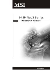
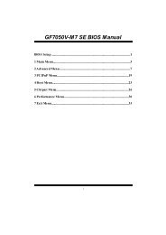
Mainboard Layout<br />
Top : mouse<br />
Bottom:<br />
keyboard<br />
Top :<br />
Parallel Port<br />
Bottom:<br />
HDMI port<br />
VGA port<br />
Top:1394<br />
Bottom: USB ports<br />
Top: LAN Jack<br />
Bottom: USB ports<br />
ALC888<br />
SYSFAN1<br />
PCI _EX2<br />
PCI1<br />
PCI 2<br />
JPW1<br />
JTV1<br />
T: Line-In<br />
M: Line-Out<br />
B: Mic<br />
T:RS-Out<br />
RTL8111B<br />
RTM870T-691<br />
M:CS-Out<br />
B:SS-Out<br />
PCI _EX1<br />
JAUD1 JCD1 SPDOUT1<br />
AMD<br />
690G/690V<br />
JSPI1<br />
CPUFAN1<br />
DIMM1<br />
DIMM2<br />
SB600<br />
K9AGM2 Series<br />
(MS-7327 v1.X) Micro- ATX Mainboard<br />
ATX1<br />
BATT<br />
+<br />
JUSB1 JUSB2 JUSB3<br />
SATA4 SATA2<br />
JBAT1<br />
FD D 1<br />
IDE 1<br />
JFP1<br />
JCI1<br />
SATA3 SATA1
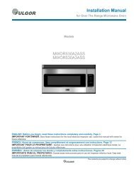
Packing Checklist<br />
MSI motherboard<br />
Power Cable<br />
User’s Guide<br />
MSI Driver/Utility CD<br />
Standard Cable for<br />
IDE Devices<br />
Getting Started<br />
SATA Cable<br />
Back IO Shield<br />
* The pictures are for reference only and may vary from the packing contents of the<br />
product you purchased.<br />
1-5
1-6<br />
MS-7327 Mainboard<br />
Setup audio output to HDMI port<br />
Install ATI HDMI Audio Driver<br />
Setup Sounds and Audio Devices<br />
To install the ATI HDMI Audio driver follow<br />
these steps<br />
1. Insert the application CD into the CD-<br />
ROM drive. The setup screen will<br />
automatically appear.<br />
2. Click ATI HDMI Audio Driver.<br />
3. Click Next to install the driver.<br />
4. Restart the <strong>com</strong>puter after the driver<br />
installation procedure.<br />
Go to: Start -> Control Panel -> Sounds<br />
and Audio Devices<br />
When the ATI HDMI Audio Driver is<br />
correctly installed, there will be one<br />
device for the Realtek HDA HDMI Out in<br />
Sound playback under Sounds and Audio<br />
Devices Properties. Select the item and<br />
then click the OK button
Chapter 2<br />
Hardware Setup<br />
Hardware Setup<br />
This chapter provides you with the information about<br />
hardware setup procedures. While doing the installation,<br />
be careful in holding the <strong>com</strong>ponents and follow the<br />
installation procedures. For some <strong>com</strong>ponents, if you<br />
install in the wrong orientation, the <strong>com</strong>ponents will not<br />
work properly.<br />
Use a grounded wrist strap before handling <strong>com</strong>puter<br />
<strong>com</strong>ponents. Static electricity may damage the<br />
<strong>com</strong>ponents.<br />
2-1
Back Panel<br />
I/O, p.2-9<br />
2-2<br />
MS-7327 Mainboard<br />
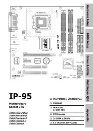
Quick Components Guide<br />
PCI Express<br />
slots, p.2-20<br />
PCI Slots,<br />
p.2-21<br />
JTV1, p.2-16<br />
JPW1, p.2-18<br />
SYSFAN1, p.2-13<br />
CPU, p.2-3<br />
DDRII DIMMs, p.2-6<br />
CPUFAN1,<br />
p.2-13<br />
J1394_1, p.2-17<br />
SPDIN1, p.2-18<br />
SPDOUT1, p.2-18<br />
JCD1, p.2-13<br />
JAUD1, p.2-14<br />
JUSB1~3,<br />
p.2-15<br />
JCI1, p.2-13<br />
FDD1, p.2-11<br />
IDE1, p.2-11<br />
ATX1, p.2-8<br />
JSPI1, p.2-18<br />
SATA1~4,<br />
p.2-12<br />
JBAT1, p.2-19<br />
JLPC1, p.2-17<br />
JFP1, p.2-14
CPU (Central Processing Unit)<br />
Hardware Setup<br />
The mainboard supports AMD ® Athlon64 X2/ Athlon64 processors. The mainboard<br />
uses a CPU socket called Socket AM2 (940-pin) for easy CPU installation. When you<br />
are installing the CPU, make sure the CPU has a heat sink and a cooling fan<br />
attached on the top to prevent overheating. If you do not have the heat sink and<br />
cooling fan, contact your dealer to purchase and install them before turning on the<br />
<strong>com</strong>puter.<br />
For the latest information about CPU, please visit http://www.msi.<strong>com</strong>.tw/program/<br />
products/mainboard/mbd/pro_mbd_cpu_support.php<br />
Important<br />
1. Overheating will seriously damage the CPU and system. Always make<br />
sure the cooling fan can work properly to protect the CPU from overheating.<br />
2. Make sure that you apply an even layer of heat sink paste (or thermal tape)<br />
between the CPU and the heatsink to enhance heat dissipation.<br />
3. While replacing the CPU, always turn off the ATX power supply or unplug<br />
the power supply’s power cord from the grounded outlet first to ensure the<br />
safety of CPU.<br />
2-3
2-4<br />
MS-7327 Mainboard<br />
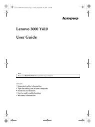
CPU Installation Procedures for Socket AM2<br />
1. Please turn off the power and<br />
unplug the power cord before<br />
installing the CPU.<br />
2. Pull the lever sideways away<br />
from the socket. Make sure to<br />
raise the lever up to a 90-degree<br />
angle.<br />
3. Look for the gold arrow of the<br />
CPU. The gold arrow should<br />
point as shown in the picture.<br />
The CPU can only fit in the correct<br />
orientation.<br />
4. If the CPU is correctly installed,<br />
the pins should be <strong>com</strong>pletely<br />
embedded into the socket and<br />
can not be seen. Please note<br />
that any violation of the correct<br />
installation procedures may<br />
cause permanent damages to<br />
your mainboard.<br />
5. Press the CPU down firmly into<br />
the socket and close the lever.<br />
As the CPU is likely to move while<br />
the lever is being closed, always<br />
close the lever with your<br />
fingers pressing tightly on top of<br />
the CPU to make sure the CPU is<br />
properly and <strong>com</strong>pletely embedded<br />
into the socket.<br />
Sliding<br />
Plate<br />
Gold arrow<br />
Gold arrow<br />
Gold arrow<br />
Open Lever<br />
90 degree<br />
Correct CPU placement<br />
O
Hardware Setup<br />
Installing AMD Socket AM2 CPU Cooler Set<br />
When you are installing the CPU, make sure the CPU has a heat sink and a<br />
cooling fan attached on the top to prevent overheating. If you do not have the<br />
heat sink and cooling fan, contact your dealer to purchase and install them before<br />
turning on the <strong>com</strong>puter.<br />
Important<br />
Mainboard photos shown in this section are for demonstration of the cooler<br />
installation for Socket AM2 CPUs only. The appearance of your mainboard<br />
may vary depending on the model you purchase.<br />
1. Position the cooling set onto the retention<br />
mechanism.<br />
Hook one end of the clip to hook<br />
first.<br />
2. Then press down the other end of<br />
the clip to fasten the cooling set on<br />
the top of the retention mechanism.<br />
Locate the Fix Lever and lift up it .<br />
Fixed Lever<br />
3. Fasten down the lever. 4. Attach the CPU Fan cable to the CPU<br />
fan connector on the mainboard.<br />
* While disconnecting the Safety Hook from the fixed bolt, it is necessary to<br />
keep an eye on your fingers, because once the Safety Hook is disconnected<br />
from the fixed bolt, the fixed lever will spring back instantly.<br />
2-5
2-6<br />
MS-7327 Mainboard<br />
Memory<br />
The mainboard provides four 240-pin non-ECC DDRII DIMMs and supports up to 4 GB<br />
system memory.<br />
For more information on <strong>com</strong>patible <strong>com</strong>ponents, please visit http://www.msi.<strong>com</strong>.tw/<br />
program/products/mainboard/mbd/pro_mbd_trp_list.php<br />
DDRII<br />
240-pin, 1.8V<br />
1<br />
56x2=112 pin<br />
Dual-Channel Memory Population Rules<br />
64x2=128 pin<br />
DIMM1<br />
DIMM2
Hardware Setup<br />
Installing DDRII Modules<br />
1. The memory module has only one notch on the center and will only fit in the right<br />
orientation.<br />
2. Insert the memory module vertically into the DIMM slot. Then push it in until the<br />
golden finger on the memory module is deeply inserted in the DIMM slot.<br />
Important<br />
You can barely see the golden finger if the memory module is properly inserted<br />
in the DIMM slot.<br />
3. The plastic clip at each side of the DIMM slot will automatically close.<br />
Important<br />
Volt Notch<br />
- DDRII modules are not interchangeable with DDR and the DDRII standard is<br />
not backwards <strong>com</strong>patible. You should always install DDRII memory modules<br />
in the DDRII DIMMs and DDR memory modules in the DDR DIMMs.<br />
- In dual-channel mode, make sure that you install memory modules of the<br />
same type and density in differentchannel DDR DIMMs.<br />
- To enable successful system boot-up, always insert the memory modules<br />
into the DIMM1 first.<br />
2-7
2-8<br />
MS-7327 Mainboard<br />
Power Supply<br />
ATX 24-Pin Power Connector: ATX1<br />
This connector allows you to connect an ATX 24-pin power supply.<br />
To connect the ATX 24-pin power supply, make sure the plug of the<br />
power supply is inserted in the proper orientation and the pins are<br />
aligned. Then push down the power supply firmly into the connector.<br />
You may use the 20-pin ATX power supply as you like. If you’d like<br />
to use the 20-pin ATX power supply, please plug your power supply<br />
along with pin 1 & pin 13 (refer to the image at the right hand).<br />
There is also a foolproof design on pin 11, 12, 23 & 24 to avoid<br />
wrong installation.<br />
Pin Definition<br />
ATX1<br />
13 1<br />
24<br />
12<br />
Important<br />
PIN SIGNAL<br />
1 +3.3V<br />
2 +3.3V<br />
3 GND<br />
4 +5V<br />
5 GND<br />
6 +5V<br />
7 GND<br />
8 PWR OK<br />
9 5VSB<br />
10 +12V<br />
11 +12V<br />
12 +3.3V<br />
PIN SIGNAL<br />
13 +3.3V<br />
14 -12V<br />
15 GND<br />
16 PS-ON#<br />
17 GND<br />
18 GND<br />
19 GND<br />
20 Res<br />
21 +5V<br />
22 +5V<br />
23 +5V<br />
24 GND<br />
ATX 12V Power Connector: JPW1<br />
This 12V power connector JPW1 is used to provide power to the CPU.<br />
JPW1<br />
4 2<br />
3<br />
1<br />
JPW1 Pin Definition<br />
PIN SIGNAL<br />
1 GND<br />
2 GND<br />
3 12V<br />
4 12V<br />
pin 13<br />
pin 12<br />
1. Maker sure that all the connectors are connected to proper ATX power supplies<br />
to ensure stable operation of the mainboard.<br />
2. Power supply of 350 watts (and above) is highly re<strong>com</strong>mended for system<br />
stability.
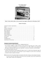
Back Panel<br />
Mouse<br />
Parallel Port<br />
Keyboard HDMI<br />
VGA USB Ports<br />
LAN<br />
Hardware Setup<br />
L-In<br />
RS-Out<br />
L-Out CS-Out<br />
Mic SS-Out<br />
PS/2 Mouse/Keyboard Connector<br />
The standard PS/2 ® mouse/keyboard DIN connector is for a PS/2 ® mouse/keyboard.<br />
Parallel Port<br />
A parallel port is a standard printer port that supports Enhanced Parallel Port (EPP)<br />
and Extended Capabilities Parallel Port (ECP) mode.<br />
HDMI Port (optional)<br />
The High-Definition Multimedia Interface (HDMI) is an all-digital audio/video interface<br />
capable of transmitting un<strong>com</strong>pressed streams. HDMI supports all TV format, including<br />
standard, enhanced, or high-definition video, plus multi-channel digital audio on a<br />
single cable.<br />
IEEE 1394 Port (optional)<br />
The 1394 port on the back panel provides connection to 1394 devices.<br />
LAN (RJ-45) Jack<br />
The standard RJ-45 jack is for connection to single Local Area Network (LAN). You<br />
can connect a network cable to it.<br />
LED Color LED State condition<br />
Activity Indicator<br />
Off LAN link is not established.<br />
Left Orange On (steady state) LAN link is established.<br />
1394<br />
Link Indicator<br />
On (brighter & pulsing)The <strong>com</strong>puter is <strong>com</strong>municating with another <strong>com</strong>puter on the LAN.<br />
Green Off 10 Mbit/sec data rate is selected.<br />
Right On 100 Mbit/sec data rate is selected.<br />
Orange On 1000 Mbit/sec data rate is selected.<br />
2-9
2-10<br />
MS-7327 Mainboard<br />
USB Connectors<br />
The OHCI (Open Host Controller Interface) Universal Serial Bus root is for attaching<br />
USB devices such as keyboard, mouse, or other USB-<strong>com</strong>patible devices.<br />
Audio Port Connectors<br />
These audio connectors are used for audio devices. You can differentiate the color<br />
of the audio jacks for different audio sound effects.<br />
Blue audio jack - Line In, is used for external CD player, tapeplayer or<br />
other audio devices.<br />
Green audio jack - Line Out, is a connector for speakers or headphones.<br />
Pink audio jack - Mic In, is a connector for microphones.<br />
Black audio jack - Rear-Surround Out in 4 / 5.1 / 7.1 channel mode.<br />
Orange audio jack - Center/ Subwoofer Out in 5.1 / 7.1 channel mode.<br />
Gray audio jack - Side-Surround Out in 7.1 channel mode.
Connectors<br />
Hardware Setup<br />
Floppy Disk Drive Connector: FDD1<br />
This standard FDD connector supports 360K, 720K, 1.2M, 1.44M and 2.88M floppy<br />
disk types.<br />
FDD1<br />
ATA133 Hard Disk Connectors: IDE1<br />
The mainboard has a 32-bit Enhanced PCI IDE and Ultra DMA 66/100/133<br />
controller that provides PIO mode 0~4, Bus Master, and Ultra DMA 66/<br />
100/133 function. You can connect hard disk drives, CD-ROM and other<br />
IDE devices.<br />
The Ultra ATA133 interface boosts data transfer rates between the<br />
<strong>com</strong>puter and the hard drive up to 133 megabytes (MB) per second. The<br />
new interface is one-third faster than earlier record-breaking Ultra ATA/<br />
100 technology and is backwards <strong>com</strong>patible with the existing Ultra ATA<br />
interface.<br />
IDE1 (Primary IDE Connector)<br />
IDE1 can connect a Master and a Slave drive. You must configure the<br />
second hard drive to Slave mode by setting the jumper accordingly. IDE1<br />
Important<br />
If you install two hard disks on IDE cable, you must configure the second<br />
drive to Slave mode by setting its jumper. Refer to the hard disk documentation<br />
supplied by hard disk vendors for jumper setting instructions.<br />
2-11
2-12<br />
MS-7327 Mainboard<br />
Serial ATA II Connectors: SATA1~SATA4<br />
SATA1~SATA4 are high-speed SATAII interface ports. Each supports data rates of<br />
300 MB/s and is fully <strong>com</strong>pliant with Serial ATA specifications. Each Serial ATA connector<br />
can connect to 1 hard disk device.<br />
SATA4<br />
7<br />
SATA2 SATA1<br />
1<br />
Serial ATA cable<br />
SATA3<br />
Connect to SATA connector<br />
Important<br />
Pin Definition<br />
PIN SIGNAL PIN SIGNAL<br />
1 GND 2 TXP<br />
3 TXN 4 GND<br />
5 RXN 6 RXP<br />
7 GND<br />
Take out the dust cover<br />
and connect to the hard<br />
disk devices<br />
Please do not fold the Serial ATA cable into 90-degree angle. Otherwise,<br />
data loss may occur during transmission.
Hardware Setup<br />
Fan Power Connectors: CPUFAN1, SYSFAN1<br />
The fan power connectors support system cooling fan with +12V. When connecting<br />
the wire to the connectors, always take note that the red wire is the positive and<br />
should be connected to the +12V, the black wire is Ground and should be connected<br />
to GND. If the mainboard has a System Hardware Monitor chipset on-board, you must<br />
use a specially designed fan with speed sensor to take advantage of the CPU fan<br />
control.<br />
Control<br />
GND<br />
SENSOR +12V<br />
CPUFAN1<br />
Important<br />
Chassis Intrusion Switch Connector: JCI1<br />
This connector connects to a 2-pin chassis switch. If the chassis is opened, the<br />
switch will be short. The system will record this status and show a warning message<br />
on the screen. To clear the warning, you must enter the BIOS utility and clear the<br />
record.<br />
CD-In Connector: JCD1<br />
This connector is provided for CD-ROM audio.<br />
JCD1<br />
GND SENSOR<br />
+12V<br />
SYSFAN1<br />
1. Please refer to the re<strong>com</strong>mended CPU fans at AMD ® official website or<br />
consult the vendors for proper CPU cooling fan.<br />
2. Always consult the vendors for proper CPU cooling fan.<br />
3. Fan/heatsink with 3 or 4 pins are both available for CPUFAN1.<br />
2<br />
1<br />
JCI1<br />
GND<br />
CINTRU<br />
L<br />
GND R<br />
2-13
2-14<br />
MS-7327 Mainboard<br />
Front Panel Audio Connector: JAUD1<br />
The JAUD1 front panel audio connector allows you to connect the front panel audio<br />
and is <strong>com</strong>pliant with Intel ® Front Panel I/O Connectivity Design Guide.<br />
1 2<br />
JAUD1<br />
JAUD1 Pin Definition<br />
PIN SIGNAL DESCRIPTION<br />
Front Panel Connectors: JFP1<br />
The mainboard provides two front panel connectors for electrical connection to the<br />
front panel switches and LEDs. The JFP1 is <strong>com</strong>pliant with Intel ® Front Panel I/O<br />
Connectivity Design Guide.<br />
JFP1<br />
9<br />
10<br />
10<br />
9<br />
1 AUD_MIC Front panel microphone input signal<br />
2 AUD_GND Ground used by analog audio circuits<br />
3 AUD_MIC_BIAS Microphone power<br />
4 AUD_VCC Filtered +5V used by analog audio circuits<br />
5 AUD_FPOUT_R Right channel audio signal to front panel<br />
6 AUD_RET_R Right channel audio signal return from front panel<br />
7 HP_ON Reserved for future use to control headphone amplifier<br />
8 KEY No pin<br />
9 AUD_FPOUT_L Left channel audio signal to front panel<br />
10 AUD_RET_L Left channel audio signal return from front panel<br />
Reset HDD<br />
Switch<br />
+ -<br />
LED<br />
- +<br />
Power<br />
Switch<br />
JFP1 Pin Definition<br />
PIN SIGNAL DESCRIPTION<br />
1 HD_LED + Hard disk LED pull-up<br />
2 FP PWR/SLP MSG LED pull-up<br />
3 HD_LED - Hard disk active LED<br />
4 FP PWR/SLP MSG LED pull-up<br />
5 RST_SW - Reset Switch low reference pull-down to GND<br />
6 PWR_SW + Power Switch high reference pull-up<br />
7 RST_SW + Reset Switch high reference pull-up<br />
8 PWR_SW - Power Switch low reference pull-down to GND<br />
9 RSVD_DNU Reserved. Do not use.<br />
-<br />
+<br />
1<br />
2<br />
Power<br />
LED
Hardware Setup<br />
Front USB Connectors: JUSB1, JUSB2 & JUSB3<br />
The mainboard provides USB 2.0 pinheaders (optional USB 2.0 bracket available) that<br />
are <strong>com</strong>pliant with Intel ® I/O Connectivity Design Guide. USB 2.0 technology increases<br />
data transfer rate up to a maximum throughput of 480Mbps, which is 40 times faster<br />
than USB 1.1, and is ideal for connecting high-speed USB interface peripherals such<br />
as USB HDD, digital cameras, MP3 players, printers, modems and the like.<br />
1 2<br />
9<br />
10<br />
1 2<br />
JUSB1<br />
JUSB2<br />
JUSB3<br />
10<br />
9<br />
Connected to USB connector<br />
1 2<br />
10<br />
9<br />
Important<br />
Pin Definition<br />
PIN SIGNAL PIN SIGNAL<br />
1 VCC 2 VCC<br />
3 USB0- 4 USB1-<br />
5 USB0+ 6 USB1+<br />
7 GND 8 GND<br />
9 Key (no pin) 10 USBOC<br />
USB 2.0 Bracket<br />
(Optional)<br />
Note that the pins of VCC and GND must be connected correctly to avoid<br />
possible damage.<br />
2-15
2-16<br />
MS-7327 Mainboard<br />
TV-Out Connector: JTV1 (Optional)<br />
The mainboard optionally provides a TV-Out connector for you to attach a TV-Out<br />
bracket that integrates HDTV-out. The TV-Out bracket offers two types of TV-Out<br />
connectors: S-Video and RCA Composite connectors. Select the appropriate one to<br />
connect to the standard television or the HDTV (High-Definition TeleVision) and it will<br />
be able to display PC’s information.<br />
Connected to JTV1<br />
3 2<br />
1<br />
5 4<br />
JTV1<br />
Important<br />
Pin Description Pin Description<br />
1 GND 4 COMP<br />
2 Y OUT 5 GND<br />
3 C OUT<br />
TV-Out Connector<br />
(RCA Composite)<br />
JTV1 Pin Definition<br />
TV-Out Bracket (Optional)<br />
TV-Out Connector<br />
(S-Video)<br />
1. Please note that the TV-Out bracket can connect to one TV only. Users<br />
have to choose either the RCA Composite or the S-Video to connect. Simultaneous<br />
connection (of this bracket) to two TVs is prohibited and may<br />
lead to the malfunction of the TVs.
Hardware Setup<br />
IEEE 1394 Connector: J1394_1<br />
The mainboard provides IEEE1394 pinheader that allows you to connect IEEE 1394<br />
ports via an external IEEE1394 bracket (optional).<br />
9<br />
1<br />
10<br />
2<br />
J1394_1<br />
Connected to 1394 connector<br />
Foolproof<br />
design<br />
Pin Definition<br />
PIN SIGNAL PIN SIGNAL<br />
1 TPA+ 2 TPA-<br />
3 Ground 4 Ground<br />
5 TPB+ 6 TPB-<br />
7 Cable power 8 Cable power<br />
9 Key (no pin) 10 Ground<br />
IEEE1394 Bracket (Optional)<br />
2-17
2-18<br />
MS-7327 Mainboard<br />
SPDIF-Out / SPDIF-In Connector: SPDOUT1 / SPDIN1 (Optional)<br />
This connector is used to connect SPDIF (Sony & Philips Digital Interconnect Format)<br />
interface for digital audio transmission.<br />
SPDOUT1<br />
GND<br />
SPDIF OUT<br />
VCC<br />
Connected to SPDOUT1 / SPDIN1<br />
JSPI Debugging Pin Header: JSPI1<br />
The pin header is for internal debugging only.<br />
9<br />
10<br />
JSPI1<br />
1<br />
2<br />
SPDIN1<br />
GND<br />
SPDIF IN<br />
VCC<br />
SPDIF Bracket (Optional)<br />
JSPI1 Pin Definition<br />
PIN SIGNAL PIN SIGNAL<br />
1 VCC3_SB 2 VCC3_SB<br />
3 SPI_MISO 4 SPI_MOSI_F<br />
5 SPI_CSO_F# 6 SPI_CLK_F<br />
7 GND 8 GND<br />
9 Reserved 10 NC
Jumpers<br />
Hardware Setup<br />
Clear CMOS Jumper: JBAT1<br />
There is a CMOS RAM onboard that has a power supply from external battery to keep<br />
the data of system configuration. With the CMOS RAM, the system can automatically<br />
boot OS every time it is turned on. If you want to clear the system configuration, set<br />
the JBAT1 (Clear CMOS Jumper ) to clear data.<br />
1<br />
JBAT1<br />
Important<br />
1 3<br />
Keep Data<br />
1 3<br />
Clear Data<br />
You can clear CMOS by shorting 2-3 pin while the system is off. Then return<br />
to 1-2 pin position. Avoid clearing the CMOS while the system is on; it will<br />
damage the mainboard.<br />
2-19
2-20<br />
MS-7327 Mainboard<br />
Slots<br />
PCI (Peripheral Component Interconnect) Express Slots<br />
PCI Express architecture provides a high performance I/O infrastructure for Desktop<br />
Platforms with transfer rates starting at 2.5 Giga transfers per second over a PCI<br />
Express x1 lane for Gigabit Ethernet, TV Tuners, 1394 controllers, and general purpose<br />
I/O. Also, desktop platforms with PCI Express Architecture will be designed to<br />
deliver highest performance in video, graphics, multimedia and other sophisticated<br />
applications. Moreover, PCI Express architecture provides a high performance graphics<br />
infrastructure for Desktop Platforms doubling the capability of existing AGP 8x designs<br />
with transfer rates of 4.0 GB/s over a PCI Express x16 lane for graphics<br />
controllers, while PCI Express x1 supports transfer rate of 250 MB/s.<br />
PCI Express x1 Slot<br />
Important<br />
PCI Express x16 Slot<br />
1. When adding or removing expansion cards, make sure that you unplug the<br />
power supply first. Meanwhile, read the documentation for the expansion<br />
card to configure any necessary hardware or software settings for the ex<br />
pansion card, such as jumpers, switches or BIOS configuration.
Hardware Setup<br />
PCI (Peripheral Component Interconnect) Slots<br />
The PCI slots support LAN cards, SCSI cards, USB cards, and other add-on cards<br />
that <strong>com</strong>ply with PCI specifications. At 32 bits and 33 MHz, it yields a throughput rate<br />
of 133 MBps.<br />
32-bit PCI Slot<br />
PCI Interrupt Request Routing<br />
The IRQ, acronym of interrupt request line and pronounced I-R-Q, are hardware lines<br />
over which devices can send interrupt signals to the microprocessor. The PCI IRQ<br />
pins are typically connected to the PCI bus pins as follows:<br />
Order 1 Order 2 Order 3 Order 4<br />
PCI Slot 1 INT A# INT B# INT C# INT D#<br />
PCI Slot 2 INT B# INT C# INT D# INT A#<br />
2-21
Chapter 3<br />
BIOS Setup<br />
BIOS Setup<br />
This chapter provides information on the BIOS Setup<br />
program and allows you to configure the system for<br />
optimum use.<br />
You may need to run the Setup program when:<br />
† An error message appears on the screen during the<br />
system booting up, and requests you to run SETUP.<br />
† You want to change the default settings for customized<br />
features.<br />
3-1
3-2<br />
MS-7327 Mainboard<br />
Entering Setup<br />
Power on the <strong>com</strong>puter and the system will start POST (Power On Self Test) process.<br />
When the message below appears on the screen, press key to enter Setup.<br />
Press DEL to enter SETUP<br />
If the message disappears before you respond and you still wish to enter Setup,<br />
restart the system by turning it OFF and On or pressing the RESET button. You may<br />
also restart the system by simultaneously pressing , , and keys.<br />
Important<br />
1. The items under each BIOS category described in this chapter are under<br />
continuous update for better system performance. Therefore, the description<br />
may be slightly different from the latest BIOS and should be held for<br />
reference only.<br />
2. Upon boot-up, the 1st line appearing after the memory count is the BIOS<br />
version. It is usually in the format:<br />
A7327AMS V1.0 050506 where:<br />
1st digit refers to BIOS maker as A = AMI, W = AWARD, and P =<br />
PHOENIX.<br />
2nd - 5th digit refers to the model number.<br />
6th digit refers to the chipset as I = Intel, N = nVidia, A = ATi and<br />
V = VIA.<br />
7th - 8th digit refers to the customer as MS = all standard customers.<br />
V1.0 refers to the BIOS version.<br />
050506 refers to the date this BIOS was released.
Control Keys<br />
BIOS Setup<br />
Getting Help<br />
After entering the Setup menu, the first menu you will see is the Main Menu.<br />
Main Menu<br />
The main menu lists the setup functions you can make changes to. You can use the<br />
arrow keys ( ↑↓ ) to select the item. The on-line description of the highlighted setup<br />
function is displayed at the bottom of the screen.<br />
Sub-Menu<br />
Move to the previous item<br />
Move to the next item<br />
Move to the item in the left hand<br />
Move to the item in the right hand<br />
Select the item<br />
Jumps to the Exit menu or returns to the main menu from a<br />
submenu<br />
Increase the numeric value or make changes<br />
Decrease the numeric value or make changes<br />
Load Optimized Defaults<br />
Save configuration changes and exit setup<br />
If you find a right pointer symbol (as shown in the<br />
right view) appears to the left of certain fields that<br />
means a sub-menu can be launched from this field. A<br />
sub-menu contains additional options for a field<br />
parameter. You can use arrow keys ( ↑↓ ) to highlight the field and press to<br />
call up the sub-menu. Then you can use the control keys to enter values and move<br />
from field to field within a sub-menu. If you want to return to the main menu, just press<br />
the .<br />
General Help <br />
The BIOS setup program provides a General Help screen. You can call up this screen<br />
from any menu by simply pressing . The Help screen lists the appropriate keys<br />
to use and the possible selections for the highlighted item. Press to exit the<br />
Help screen.<br />
3-3
3-4<br />
MS-7327 Mainboard<br />
The Main Menu<br />
Standard CMOS Features<br />
Use this menu for basic system configurations, such as time, date etc.<br />
Advanced BIOS Features<br />
Use this menu to setup the items of AMI ® special enhanced features.<br />
Advanced Chipset Features<br />
Use this menu to change the values in the chipset registers and optimize your system’s<br />
performance.<br />
Integrated Peripherals<br />
Use this menu to specify your settings for integrated peripherals.<br />
Power Management Setup<br />
Use this menu to specify your settings for power management.<br />
PNP/PCI Configurations<br />
This entry appears if your system supports PnP/PCI.<br />
H/W Monitor<br />
This entry shows your PC health status.<br />
Load Optimized Defaults<br />
Use this menu to load the default values set by the mainboard manufacturer specifically<br />
for optimal performance of the mainboard.
BIOS Setting Password<br />
Use this menu to set the password for BIOS.<br />
Save & Exit Setup<br />
Save changes to CMOS and exit setup.<br />
Exit Without Saving<br />
Abandon all changes and exit setup.<br />
BIOS Setup<br />
3-5
3-6<br />
MS-7327 Mainboard<br />
Standard CMOS Features<br />
The items in Standard CMOS Features Menu includes some basic setup items. Use<br />
the arrow keys to highlight the item and then use the or keys to select<br />
the value you want in each item.<br />
Date (MM:DD:YY)<br />
This allows you to set the system to the date that you want (usually the current date).<br />
The format is .<br />
day Day of the week, from Sun to Sat, determined by<br />
BIOS. Read-only.<br />
month The month from Jan. through Dec.<br />
date The date from 1 to 31 can be keyed by numeric function keys.<br />
year The year can be adjusted by users.<br />
Time (HH:MM:SS)<br />
This allows you to set the system time that you want (usually the current time). The<br />
time format is .<br />
Primary IDE Master/ Slave, (Third/ Fourth IDE Master/ Slave => for SATA<br />
devices)<br />
Press to enter the sub-menu, and the following screen appears.<br />
Important<br />
Primary IDE Master/ Slave, Third/ Fourth IDE Master/ Slave are<br />
appearing when you connect the HD devices to the IDE/ SATA connector<br />
on the mainboard.
BIOS Setup<br />
Device/ Vender/ Size<br />
It will showing the device information that you connected to the IDE/SATA<br />
connector.<br />
LBA/Large Mode<br />
This allows you to enable or disable the LBA Mode. Setting to Auto enables LBA<br />
mode if the device supports it and the devices is not already formatted with LBA<br />
mode disabled.<br />
DMA Mode<br />
Select DMA Mode.<br />
Hard Disk S.M.A.R.T.<br />
This allows you to activate the S.M.A.R.T. (Self-Monitoring Analysis & Reporting<br />
Technology) capability for the hard disks. S.M.A.R.T is a utility that monitors your<br />
disk status to predict hard disk failure. This gives you an opportunity to move<br />
data from a hard disk that is going to fail to a safe place before the hard disk<br />
be<strong>com</strong>es offline.<br />
Floppy A<br />
This item allows you to set the type of floppy drives installed.<br />
Halt On<br />
The setting determines whether the system will stop if an error is detected at boot.<br />
Available options are:<br />
[No Errors] The system doesn’t stop for any detected error.<br />
[All, But Keyboard] The system doesn’t stop for a keyboard error.<br />
3-7
3-8<br />
MS-7327 Mainboard<br />
System Information<br />
Press to enter the sub-menu, and the following screen appears.<br />
CPU Infromation/ BIOS Version/ Memory Information<br />
These items show the CPU information, BIOS version and memory status of your<br />
system (read only).
Advanced BIOS Features<br />
BIOS Setup<br />
Full Screen LOGO Display<br />
This item enables you to show the <strong>com</strong>pany logo on the bootup screen. Settings are:<br />
[Enabled] Shows a still image (logo) on the full screen at boot.<br />
[Disabled] Shows the POST messages at boot.<br />
Quick Booting<br />
Setting the item to [Enabled] allows the system to boot within 5 seconds since it will<br />
skip some check items.<br />
Boot Up Num-Lock LED<br />
This setting is to set the Num Lock status when the system is powered on. Setting to<br />
[On] will turn on the Num Lock key when the system is powered on. Setting to [Off]<br />
will allow users to use the arrow keys on the numeric keypad.<br />
Boot To OS/2<br />
This allows you to run the OS/2 ® operating system with DRAM larger than 64MB.<br />
When you choose [No], you cannot run the OS/2 ® operating system with DRAM<br />
larger than 64MB. But it is possible if you choose [Yes].<br />
IOAPIC Function<br />
This field is used to enable or disable the APIC (Advanced Programmable Interrupt<br />
Controller). Due to <strong>com</strong>pliance with PC2001 design guide, the system is able to run in<br />
APIC mode. Enabling APIC mode will expand available IRQ resources for the system.<br />
3-9
3-10<br />
MS-7327 Mainboard<br />
MPS Table Version<br />
This field allows you to select which MPS (Multi-Processor Specification) version to<br />
be used for the operating system. You need to select the MPS version supported by<br />
your operating system. To find out which version to use, consult the vendor of your<br />
operating system.<br />
Boot Sequence<br />
Press to enter the sub-menu and the following screen appears:<br />
1st/2nd/3rd Boot Device<br />
The items allow you to set the sequence of boot devices where BIOS attempts<br />
to load the disk operating system.<br />
Boot From Other Device<br />
Setting the option to [Yes] allows the system to try to boot from other device if<br />
the system fails to boot from the 1st/2nd/3rd boot device.<br />
Hard Disk Drives<br />
This feature allows you to specify the hard disk boot priority.<br />
Removable Drives<br />
This feature allows you to specify the removable device boot priority.<br />
CD/DVD Drives<br />
This feature allows you to specify the CD/DVD device boot priority.
Advanced Chipset Features<br />
BIOS Setup<br />
DRAM Timing<br />
The value in this field depends on performance parameters of the installed memory<br />
chips (DRAM). Do not change the value from the factory setting unless you install<br />
new memory that has a different performance rating than the original DRAMs.<br />
CAS# Latency (Tcl)<br />
This controls the CAS latency, which determines the timing delay (in clock cycles)<br />
before SDRAM starts a read <strong>com</strong>mand after receiving it.<br />
Min RAS# Active Time (Tras)<br />
This setting determines the time RAS takes to read from and write to a memory cell.<br />
RAS# Precharge Time (Trp)<br />
This item controls the number of cycles for Row Address Strobe (RAS) to be allowed<br />
to precharge. If insufficient time is allowed for the RAS to accumulate its charge<br />
before DRAM refresh, refreshing may be in<strong>com</strong>plete and DRAM may fail to retain<br />
data. This item applies only when synchronous DRAM is installed in the system.<br />
RAS# to CAS# Delay (Trcd)<br />
When DRAM is refreshed, both rows and columns are addressed separately. This<br />
setup item allows you to determine the timing of the transition from RAS (row address<br />
strobe) to CAS (column address strobe). The less the clock cycles, the faster the<br />
DRAM performance.<br />
VGA Share Memory Size<br />
The system shares memory to the onboard VGA card. This setting controls the exact<br />
memory size shared to the VGA card.<br />
3-11
3-12<br />
MS-7327 Mainboard<br />
Surround View<br />
SurroundView Technology that allows you to add an ATI external graphics card to<br />
enable three separate displays.<br />
Display Device Select<br />
This item allows you to select the display device.<br />
TV NTSC/PAL Display Select<br />
This item allows you to select NTSC or PAL signal.
Integrated Peripherals<br />
BIOS Setup<br />
USB Controller<br />
This setting allows you to enable/disable the onboard USB 1.1/ 2.0 controller.<br />
USB Device Legacy Support<br />
Select [Enabled] if you need to use a USB-interfaced device in the operating system.<br />
Onboard LAN Controller<br />
This setting allows you to enable/disable the onboard LAN controller.<br />
LAN Option ROM<br />
This item is used to decide whether to invoke the Boot ROM of the onboard LAN.<br />
Onboard IEEE1394 Controller<br />
This item allows you to enable/disable the onboard IEEE1394 controller.<br />
Onboard Audio Controller<br />
This setting is used to enable/disable the onboard audio controller.<br />
IDE Devices Configuration<br />
Press to enter the sub-menu:<br />
PCI IDE BusMaster<br />
This item allows you to enable/ disable BIOS to used PCI busmastering for<br />
reading/ writing to IDE drives.<br />
OnChip SATA Channel<br />
This item allows users to enable or disable the SATA controller.<br />
3-13
3-14<br />
MS-7327 Mainboard<br />
OnChip SATA Type<br />
This item is used to define the SATA type. Before configure the RAID set, you<br />
have to choose the RAID for the SATA devices.<br />
I/O Devices Configuration<br />
Press to enter the sub-menu:<br />
Parallel Port<br />
There is a built-in parallel port on the on-board Super I/O chipset that provides<br />
Standard, ECP, and EPP features. It has the following options:<br />
[Disabled]<br />
[3BC] Line Printer port 0<br />
[278] Line Printer port 2<br />
[378] Line Printer port 1<br />
Parallel Port Mode<br />
[Normal] Standard Parallel Port<br />
[EPP] Enhanced Parallel Port<br />
[ECP] Extended Capability Port<br />
[ECP + EPP] Extended Capability Port + Enhanced Parallel Port<br />
[Bi Directional]<br />
To operate the onboard parallel port as Standard Parallel Port only, choose<br />
[Normal]. To operate the onboard parallel port in the EPP mode simultaneously,<br />
choose [EPP]. By choosing [ECP], the onboard parallel port will operate in ECP<br />
mode only. Choosing [ECP + EPP] will allow the onboard parallel port to support<br />
both the ECP and EPP modes simultaneously.
Power Management Setup<br />
Important<br />
BIOS Setup<br />
S3-related functions described in this section are available only when your<br />
BIOS supports S3 sleep mode.<br />
ACPI Function<br />
This item is to activate the ACPI (Advanced Configuration and Power Management<br />
Interface) Function. If your operating system is ACPI-aware, such as Windows 98SE/<br />
2000/ME/ XP, select [Enabled].<br />
ACPI Standby State<br />
This item specifies the power saving modes for ACPI function. If your operating<br />
system supports ACPI, such as Windows 2000/ XP , you can choose to enter the<br />
Standby mode in S1(POS) or S3(STR) fashion through the setting of this field. Settings<br />
are:<br />
[S1/POS] The S1 sleep mode is a low power state. In this state, no<br />
system context is lost (CPU or chipset) and hardware maintains<br />
all system context.<br />
[S3/STR] The S3 sleep mode is a lower power state where the in<br />
formation of system configuration and open applications/files<br />
is saved to main memory that remains powered while most<br />
other hardware <strong>com</strong>ponents turn off to save energy. The<br />
information stored in memory will be used to restore the system<br />
when a “wake up” event occurs.<br />
3-15
3-16<br />
MS-7327 Mainboard<br />
Re-Call VGA BIOS from S3<br />
Selecting [Enabled] allows BIOS to call VGA BIOS to initialize the VGA card when<br />
system wakes up (resumes) from S3 sleep state. The system resume time is shortened<br />
when you disable the function, but system will need an AGP driver to initialize<br />
the VGA card. Therefore, if the AGP driver of the card does not support the initialization<br />
feature, the display may work abnormally or not function after resuming from S3.<br />
Suspend Time Out (Minute)<br />
If system activity is not detected for the length of time specified in this field, all<br />
devices except CPU will be shut off.<br />
Power Button Function<br />
This feature sets the function of the power button. Settings are:<br />
[Power On/ Off] The power button functions as normal power off<br />
button.<br />
[Suspend] When you press the power button, the <strong>com</strong>puter enters the<br />
suspend/sleep mode, but if the button is pressed for more<br />
than four seconds, the <strong>com</strong>puter is turned off.<br />
Restore On AC Power Loss<br />
This item specifies whether your system will reboot after a power failure or interrupt<br />
occurs. Settings are:<br />
[Off] Always leaves the <strong>com</strong>puter in the power off state.<br />
[On] Always leaves the <strong>com</strong>puter in the power on state.<br />
[Last State] Restores the system to the status before power failure<br />
or interrupt occurred.<br />
Wakeup Event Setup<br />
Press to enter the sub-menu:<br />
Resume From S3 By USB Device<br />
The item allows the activity of the USB device to wake up the system from S3<br />
(Suspend to RAM) sleep state.<br />
Resume From S3 By PS/2 Keyboard<br />
This controls how the PS/2 keyboard is able to power on the system. If you<br />
choose Specific Key, the power button on the case will not function anymore<br />
and you must type the password to power on the system.<br />
Specific Key PowerOn<br />
If Resume From S3 By PS/2 Keyboard is set to [Specific Key], then you can<br />
set the specific key in the field for the PS/2 keyboard to power on the system.<br />
Resume from S3 By PS/2 Mouse<br />
This setting determines whether the system will be awakened from what power<br />
saving modes when input signal of the PS/2 mouse is detected.<br />
Resume by PCI Device (PME#)<br />
When set to [Enabled], the feature allows your system to be awakened from the
BIOS Setup<br />
power saving modes through any event on PME (Power Management Event).<br />
Resume by PCIE Device<br />
When set to [Enabled], the feature allows your system to be awakened from the<br />
power saving modes through any event on PCIE device.<br />
Resume by RTC Alarm<br />
The field is used to enable or disable the feature of booting up the system on a<br />
scheduled time/date.<br />
3-17
3-18<br />
MS-7327 Mainboard<br />
PNP/PCI Configurations<br />
This section describes configuring the PCI bus system and PnP (Plug & Play) feature.<br />
PCI, or Peripheral Component Interconnect, is a system which allows I/O devices to<br />
operate at speeds nearing the speed the CPU itself uses when <strong>com</strong>municating with<br />
its special <strong>com</strong>ponents. This section covers some very technical items and it is<br />
strongly re<strong>com</strong>mended that only experienced users should make any changes to the<br />
default settings.<br />
Primary Video Controller<br />
This setting specifies which graphic card is your primary graphics adapter.<br />
PCI Latency Timer<br />
This item controls how long each PCI device can hold the bus before another takes<br />
over. When set to higher values, every PCI device can conduct transactions for a<br />
longer time and thus improve the effective PCI bandwidth. For better PCI performance,<br />
you should set the item to higher values.<br />
PCI Slot 1/2 IRQ<br />
This setting specifies IRQ for PCI devices.<br />
IRQ Resources Setup<br />
Press and you will enter the sub-menu of the items. IRQ Resources list IRQ<br />
3/4/5/7/9/10/11/12/14/15 for users to set each IRQ a type depending on the type of<br />
device using the IRQ. Settings are:<br />
PCI Device For Plug & Play <strong>com</strong>patible devices designed for PCI bus<br />
architecture.<br />
Reserved The IRQ will be reserved for further request.
BIOS Setup<br />
DMA Resources Setup<br />
Press and you will enter the sub-menu of the items.DMA Resources 0/1/3/5/<br />
6/7 for setting determine if BIOS should remove a DMA from the available DMAs<br />
passed to devices that are configurable by the system BIOS. The available DMA pool<br />
is determined by reading the NVRAM. If more DMAs must be removed from the pool,<br />
the end user can reserve the DMA.<br />
3-19
3-20<br />
MS-7327 Mainboard<br />
H/W Monitor<br />
Auto Disable PCI Clock<br />
This item is used to auto disable the PCI slots. When set to [Enabled], the system will<br />
remove (turn off) clocks from empty PCI slots to minimize the electromagnetic interference<br />
(EMI).<br />
Spread Spectrum<br />
When the motherboard’s clock generator pulses, the extreme values (spikes) of the<br />
pulses creates EMI (Electromagnetic Interference). The Spread Spectrum function<br />
reduces the EMI generated by modulating the pulses so that the spikes of the pulses<br />
are reduced to flatter curves. If you do not have any EMI problem, leave the setting at<br />
[Disabled] for optimal system stability and performance. But if you are plagued by EMI,<br />
select the desired range for EMI reduction. Remember to disable Spread Spectrum<br />
function if you are overclocking, because even a slight jitter can introduce a temporary<br />
boost in clock speed which may just cause your overclocked processor to lock<br />
up.<br />
Chassis Intrusion<br />
The field enables or disables the feature of recording the chassis intrusion status<br />
and issuing a warning message if the chassis is once opened. To clear the warning<br />
message, set the field to [Reset]. The setting of the field will automatically return to<br />
[Enabled] later.<br />
Cool’n’Quiet<br />
It provides a CPU temperature detecting function to prevent your CPU’s from<br />
overheading due to the heavy working loading.
BIOS Setup<br />
Smart Fan Target<br />
The mainboard provides the Smart Fan system which can control the fan speed<br />
automatically depending on the current temperature to keep it with in a specific range.<br />
Smart Fan Tolerance<br />
You can select a fan tolerance value here for the specific range for the “Smart Fan<br />
Target Temp. ( o C)” item. If the current temperature of the fan reaches to the maximum<br />
threshold (the temperatures set in the “Smart Fan Target Temp. ( o C)” plus the tolerance<br />
values you set here), the fan will speed up for cooling down. On the contrary,<br />
if the current temperature reaches to the minimum threshold (the set temperatures<br />
minus the tolerance value), the fan will slow down to keep the temperature stable.<br />
Min. FAN Speed (%)<br />
This item allows you to set the minimum CPU fan speed.<br />
CPU FAN PIN Select<br />
Be sure to select the correct pin number identical to the pin of the CPU fan you<br />
purchase.<br />
PC Health Status<br />
Press to enter the sub-menu and following screen appears.<br />
CPU/System Temperature, CPU FAN/ SYSTEM FAN Speed, CPU Vcore,<br />
3.3VCC, 5V, 12V, 3.3V SB<br />
These items display the current status of all of the monitored hardware devices/<br />
<strong>com</strong>ponents such as CPU voltage, temperatures and all fans’ speeds.<br />
3-21
3-22<br />
MS-7327 Mainboard<br />
Load Optimized Defaults<br />
The option on the main menu allow users to restore all of the BIOS settings to the<br />
Optimized values. The Optimized are the default values set by the mainboard<br />
manufacturer specifically for optimal performance of the mainboard.<br />
When you select Load Optimized Defaults, a message as below appears:<br />
Selecting [OK] loads the default factory settings for optimal system performance.<br />
BIOS Setting Password<br />
When you select this function, a message as below will appear on the screen:<br />
Type the password, up to six characters in length, and press . The password<br />
typed now will replace any previously set password from CMOS memory. You will<br />
be prompted to confirm the password. Retype the password and press . You<br />
may also press to abort the selection and not enter a password.<br />
To clear a set password, just press when you are prompted to enter the<br />
password. A message will show up confirming the password will be disabled. Once<br />
the password is disabled, the system will boot and you can enter Setup without<br />
entering any password.<br />
When a password has been set, you will be prompted to enter it every time you try<br />
to enter Setup. This prevents an unauthorized person from changing any part of your<br />
system configuration.
Appendix A<br />
Realtek ALC888 Audio<br />
The Realtek ALC888 provides 10-channel DAC that simultaneously<br />
supports 7.1 sound playback and 2 channels<br />
of independent stereo sound output (multiple<br />
streaming) through the Front-Out-Left and Front-Out-<br />
Right channels.
A-2<br />
MS-7327 Mainboard<br />
Installing the Realtek HD Audio Driver<br />
You need to install the driver for Realtek ALC888 codec to function properly before<br />
you can get access to 2-, 4-, 6-, 8- channel or 7.1+2 channel audio operations.<br />
Follow the procedures described below to install the drivers for different operating<br />
systems.<br />
Installation for Windows 2000/XP<br />
For Windows ® 2000, you must install Windows ® 2000 Service Pack4 or later before<br />
installing the driver. For Windows ® XP, you must install Windows ® XP Service Pack1<br />
or later before installing the driver.<br />
The following illustrations are based on Windows ® XP environment and could look<br />
slightly different if you install the drivers in different operating systems.<br />
1. Insert the application CD into the CD-ROM drive. The setup screen will automatically<br />
appear.<br />
2. Click Realtek HD Audio Driver.<br />
Important<br />
Click here<br />
The HD Audio Configuration software utility is under continuous update<br />
to enhance audio applications. Hence, the program screens shown here in<br />
this section may be slightly different from the latest software utility and shall<br />
be held for reference only.
3. Click Next to install the Realtek High Definition Audio Driver.<br />
4. Click Finish to restart the system.<br />
Realtek ALC888 Audio<br />
Click here<br />
Click here<br />
Select this<br />
option<br />
A-3
A-4<br />
MS-7327 Mainboard<br />
Software Configuration<br />
After installing the audio driver, you are able to use the 2-, 4-, 6- or 8- channel audio<br />
feature now. Click the audio icon from the system tray at the lower-right corner of<br />
the screen to activate the HD Audio Configuration. It is also available to enable the<br />
audio driver by clicking the Realtek HD Audio Manager from the Control Panel.<br />
Double click
Sound Effect<br />
Realtek ALC888 Audio<br />
Here you can select a sound effect you like from the Environment list.<br />
Environment Simulation<br />
You will be able to enjoy different sound experience by pulling down the arrow,<br />
totally 23 kinds of sound effect will be shown for selection. Realtek HD Audio Sound<br />
Manager also provides five popular settings “Stone Corridor”, “Bathroom”, “Sewer<br />
pipe”, “Arena” and “Audio Corridor” for quick enjoyment.<br />
You may choose the provided sound effects, and the equalizer will adjust automatically.<br />
If you like, you may also load an equalizer setting or make an new equalizer setting to<br />
save as an new one by using the “Load EQ Setting” and “Save Preset” button,<br />
click “Reset EQ Setting” button to use the default value, or click “Delete EQ Setting”<br />
button to remove a preset EQ setting.<br />
There are also other pre-set equalizer models for you to choose by clicking “Others”<br />
under the Equalizer part.<br />
A-5
A-6<br />
MS-7327 Mainboard<br />
Equalizer Selection<br />
Equalizer frees users from default settings; users may create their owned preferred<br />
settings by utilizing this tool.<br />
10 bands of equalizer, ranging from 100Hz to 16KHz.<br />
Save<br />
The settings are saved<br />
permanently for future<br />
use<br />
Enable / Disable<br />
To disable, you can temporarily<br />
stop the sound<br />
effect without losing the<br />
settings<br />
Reset<br />
10 bands of equalizer<br />
would go back to the default<br />
setting<br />
Load<br />
Whenever you would like to<br />
use preload settings, simply<br />
click this, the whole list will<br />
be shown for your selection.<br />
Delete<br />
To delete the pre-saved settings which are created from previous steps.
Realtek ALC888 Audio<br />
Frequently Used Equalizer Setting<br />
Realtek recognizes the needs that you might have. By leveraging our long experience<br />
at audio field, Realtek HD Audio Sound Manager provides you certain optimized equalizer<br />
settings that are frequently used for your quick enjoyment.<br />
[How to Use It]<br />
Other than the buttons “Pop” “Live” “Club” & “Rock” shown on the page, to pull down<br />
the arrow in “Others”, you will find more optimized settings available to you.<br />
Karaoke Mode<br />
Karaoke mode brings Karaoke fun back home. Simply using the music you usually<br />
play, Karaoke mode can help you eliminate the vocal of the song or adjust the key to<br />
ac<strong>com</strong>modate your range.<br />
1.Vocal Cancellation: Single click on “Voice Cancellation”, the vocal of the song would<br />
be eliminated, while the background music is still in place, and you can be that<br />
singer!<br />
2.Key Adjustment: Using “Up / Down Arrow” to find a key which better fits your vocal<br />
range.<br />
Remove the<br />
human voice<br />
Raise the key<br />
Lower the key<br />
A-7
A-8<br />
MS-7327 Mainboard<br />
Mixer<br />
In the Mixer part, you may adjust the volumes of the rear and front panels individually.<br />
1. Adjust Volume<br />
You can adjust the volume of the speakers that you pluged in front or rear panel by<br />
select the Realtek HD Audio rear output or Realtek HD Audio front output<br />
items.<br />
Important<br />
Before set up, please make sure the playback devices are well plugged in the<br />
jacks on the rear or front panel. The Realtek HD Audio front output item<br />
will appear after you pluging the speakers into the jacks on the front panel.<br />
2. Multi-Stream Function<br />
ALC888 supports an outstanding feature called Multi-Stream, which means you may<br />
play different audio sources simultaneously and let them output respectively from the<br />
indicated real panel or front panel. This feature is very helpful when 2 people are<br />
using the same <strong>com</strong>puter together for different purposes.<br />
Click the button and the Mixer ToolBox menu will appear. Then check the Enable<br />
playback multi-streaming and click OK to save the setup.<br />
Important<br />
If you use AC97 front panel, the device have to be plugged into the jacks on<br />
the panel before enable the multi-stream function.
Realtek ALC888 Audio<br />
When you are playing the first audio source (for example: use Windows Media<br />
Player to play DVD/VCD), the output will be played from the rear panel, which is the<br />
default setting.<br />
Then you must to select the Realtek HD Audio front output from the scroll list<br />
first, and use a different program to play the second audio source (for example: use<br />
Winamp to play MP3 files). You will find that the second audio source (MP3 music) will<br />
<strong>com</strong>e out from the Line-Out audio jack of Front Panel.<br />
A-9
A-10<br />
MS-7327 Mainboard<br />
3. Playback control<br />
Tool Mute<br />
Playback device<br />
This function is to let you freely decide which ports to<br />
output the sound. And this is essential when multi-<br />
streaming playback enabled.<br />
- Realtek HD Audio Rear Output<br />
- Realtek HD Audio Front Output<br />
Mute<br />
You may choose to mute single or multiple volume controls or to <strong>com</strong>pletely mute<br />
sound output.<br />
Tool<br />
- Show the following volume controls<br />
This is to let you freely decide which volume control items to be displayed.<br />
- Advanced controls<br />
- Enable playback multi-streaming<br />
With this function, you will be able to have an audio chat with your friends via<br />
headphone (stream 1 from front panel) while still have music (stream 2 from back<br />
panel) in play. At any given period, you can have maximum 2 streams operating<br />
simultaneously.
4. Recording control<br />
Tool Mute<br />
Realtek ALC888 Audio<br />
Recording device<br />
-Back Line in/Mic, Front Lin in<br />
-Realtek HD Audio Input<br />
Mute<br />
You may choose to mute single or multiple volume controls or to <strong>com</strong>pletely mute<br />
sound input.<br />
Tool<br />
- Show the following volume controls<br />
This is to let you freely decide which volume control items to be displayed.<br />
- Enable recording multi-streaming<br />
Important<br />
ALC888 allows you to record the CD, Line, Mic and Stereo Mix channels<br />
simultaneously, frees you from mixing efforts. At any given period, you may<br />
choose 1 of the following 4 channels to record.<br />
A-11
Audio I/O<br />
A-12<br />
MS-7327 Mainboard<br />
In this tab, you can easily configure your multi-channel audio function and speakers.<br />
You can choose a desired multi-channel operation here.<br />
a. Headphone for the <strong>com</strong>mon headphone<br />
b. 2CH Speaker for Stereo-Speaker Output<br />
c. 4CH Speaker for 4-Speaker Output<br />
d. 6CH Speaker for 5.1-Speaker Output<br />
e. 8CH Speaker for 7.1-Speaker Output<br />
Speaker Configuration:<br />
1. Plug the speakers in the corresponding jack.<br />
2. Dialogue “connected device” will pop up for your selection. Please select the<br />
device you have plugged in.<br />
- If the device is being plugged into the correct jack, you will be able to find the icon<br />
beside the jack changed to the one that is same as your device.<br />
- If not correct, Realtek HD Audio Manager will guide you to plug the device into the<br />
correct jack.
Connector Settings<br />
Click to access connector settings.<br />
Realtek ALC888 Audio<br />
Disable front panel jack detection (option)<br />
Find no function on front panel jacks? Please check if front jacks on your system are<br />
so-called AC’97 jacks. If so, please check this item to disable front panel jack detection.<br />
Mute rear panel output when front headphone plugged in.<br />
Enable auto popup dialogue, when device has been plugged in<br />
Once this item checked, the dialog “Connected device” would not automatically pop<br />
up when device plugged in.<br />
A-13
A-14<br />
MS-7327 Mainboard<br />
S/PDIF<br />
Short for Sony/Philips Digital Interface, a standard audio file transfer format. S/PDIF<br />
allows the transfer of digital audio signals from one device to another without having<br />
to be converted first to an analog format. Maintaining the viability of a digital signal<br />
prevents the quality of the signal from degrading when it is converted to analog.<br />
Output Sampling Rate<br />
44.1KHz: This is re<strong>com</strong>mend while playing CD.<br />
48KHz: This is re<strong>com</strong>mended while playing DVD or Dolby.<br />
96KHz: This is re<strong>com</strong>mended while playing DVD-Audio.<br />
192KHz: This is re<strong>com</strong>mended while playing High quality Audio.<br />
Output Source<br />
Output digital audio source: The digital audio format (such as .wav, .mp3,.midi etc)<br />
will <strong>com</strong>e out through S/PDIF-Out.<br />
S/PDIF-in to S/PDIF -out pass though mode: The data from S/PDIF-In can be realtime<br />
played from S/PDIF-Out.
Test Speakers<br />
Realtek ALC888 Audio<br />
You can select the speaker by clicking it to test its functionality. The one you select<br />
will light up and make testing sound. If any speaker fails to make sound, then check<br />
whether the cable is inserted firmly to the connector or replace the bad speakers<br />
with good ones. Or you may click the auto test button to test the sounds of<br />
each speaker automatically.<br />
Front Left<br />
Side Left<br />
Rear Left<br />
Center<br />
Front Right<br />
Side Right<br />
Subwoofer<br />
Rear Right<br />
A-15
A-16<br />
MS-7327 Mainboard<br />
Microphone<br />
In this tab you may set the function of the microphone. Select the Noise Suppression<br />
to remove the possible noise during recording, or select Acoustic Echo<br />
Cancelltion to cancel the acoustic echo druing recording.<br />
Acoustic Echo Cancelltion prevents playback sound from being recorded by microphone<br />
together with your sound. For example, you might have chance to use<br />
VOIP function through Internet with your friends. The voice of your friend will <strong>com</strong>e<br />
out from speakers (playback). However, the voice of your friend might also be<br />
recorded into your microphone then go back to your friend through Internet. In that<br />
case, your friend will hear his/her own voice again. With AEC(Acoustic Echo<br />
Cancellation) enabled at your side, your friend can enjoy the benefit with less echo.
3D Audio Demo<br />
Realtek ALC888 Audio<br />
In this tab you may adjust your 3D positional audio before playing 3D audio applications<br />
like gaming. You may also select different environment to choose the most<br />
suitable environment you like.<br />
A-17
A-18<br />
MS-7327 Mainboard<br />
Information<br />
In this tab it provides some information about this HD Audio Configuration utility,<br />
including Audio Driver Version, DirectX Version, Audio Controller & Audio Codec. You<br />
may also select the language of this utility by choosing from the Language list.<br />
Also there is a selection Show icon in system tray. Switch it on and an icon<br />
will show in the system tray. Right-click on the icon and the Audio Accessories<br />
dialogue box will appear which provides several multimedia features for you to take<br />
advantage of.
Hardware Setup<br />
Realtek ALC888 Audio<br />
Connecting the Speakers<br />
When you have set the Multi-Channel Audio Function mode properly in the software<br />
utility, connect your speakers to the correct phone jacks in accordance with the<br />
setting in software utility.<br />
n 2-Channel Mode for Stereo-Speaker Output<br />
Refer to the following diagram and caption for the function of each phone jack on the<br />
back panel when 2-Channel Mode is selected.<br />
1 Line In<br />
2 Line Out (Front channels)<br />
3 MIC<br />
Back Panel<br />
4 Line Out (Rear channels, but no functioning in this mode)<br />
5 Line Out (Center and Subwoofer channel, but no functioning in this mode)<br />
6 Line Out (Side Surround channels, but no functioning in this mode)<br />
2<br />
3<br />
1<br />
4<br />
5<br />
6<br />
A-19
A-20<br />
MS-7327 Mainboard<br />
n 4-Channel Mode for 4-Speaker Output<br />
4-Channel Analog Audio Output<br />
1 Line In<br />
2 Line Out (Front channels)<br />
3 MIC<br />
4 Line Out (Rear channels)<br />
2<br />
1<br />
3<br />
Back Panel<br />
Description:<br />
Connect two speakers to back<br />
panel’s Line Out connector and<br />
two speakers to the real-channel<br />
Line Out connector.<br />
5 Line Out (Center and Subwoofer channel, but no functioning in this mode)<br />
6 Line Out (Side Surround channels, but no functioning in this mode)<br />
4<br />
5<br />
6
n 6-Channel Mode for 6-Speaker Output<br />
6-Channel Analog Audio Output<br />
1 Line In<br />
2 Line Out (Front channels)<br />
3 MIC<br />
4 Line Out (Rear channels)<br />
5 Line Out (Center and Subwoofer channel)<br />
2<br />
1<br />
3<br />
Back Panel<br />
Realtek ALC888 Audio<br />
Description:<br />
Connect two speakers to back<br />
panel’s Line Out connector, two<br />
speakers to the rear-channel<br />
Line out connector and two<br />
speakers to the center/<br />
subwoofer-channel Line Out<br />
connector.<br />
6 Line Out (Side Surround channels, but no functioning in this mode)<br />
4<br />
5<br />
6<br />
A-21
A-22<br />
MS-7327 Mainboard<br />
n 8-Channel Mode for 8-Speaker Output<br />
8-Channel Analog Audio Output<br />
1 Line In<br />
2 Line Out (Front channels)<br />
3 MIC<br />
4 Line Out (Rear channels)<br />
5 Line Out (Center and Subwoofer channel)<br />
6 Line Out (Side Surround channels)<br />
2<br />
1<br />
3<br />
4<br />
5<br />
6<br />
Description:<br />
Connect two speakers to back<br />
panel’s Line Out connector, two<br />
speakers to the rear-channel<br />
Line out connector, two speakers<br />
to the center/subwooferchannel<br />
Line Out connector and<br />
two speakers to the side-channel<br />
Line Out connector.
Appendix B<br />
ATi SATA RAID<br />
ATi SATA RAID<br />
ATi south bridge SB600 integrate SATA host controller<br />
that supports four SATAII ports and RAID function for<br />
performance and reliability.<br />
SATA RAID provides support for RAID 0 (Striping), RAID<br />
1 (Mirroring), RAID 0+1 (Striping & Mirroring). RAID 0<br />
greatly improves hard disk I/O performance by<br />
concurrently striping data across multiple drives. RAID<br />
1 makes sure data is not lost if a drive fails as data is<br />
simultaneously written to two drives. Drives configured<br />
for RAID Striping are said to form a RAID 0 set, while<br />
drives configured for RAID Mirroring are said to form a<br />
RAID 1 set. RAID 0+1 is implemented as a mirrored<br />
array whose segments are RAID 0 arrays. RAID 0+1<br />
has same fault tolerance as mirroring and reduces<br />
overhead by striping. It needs at least four drives to<br />
form a RAID 0+1.<br />
B-1
B-2<br />
MS-7280 Mainboard<br />
RAID Configuration<br />
Creating and deleting RAID set and performing other RAID setting up operations are<br />
done in the RAID BIOS. During bootup, a screen similar to the one below will appear<br />
for about few seconds. Press to enter the FastBuild utility.<br />
Important<br />
Be sure to set the OnChip SATA Type to “RAID” in BIOS (the path is :<br />
Intergrated Peripherals => IDE Devices Configuration => OnChip SATA<br />
Type) before configuting the RAID BIOS.<br />
The Fast Build Utility menu screen will appear. The Main Menu is used to choose the<br />
operation to be performed.
View Drives Assignments<br />
ATi SATA RAID<br />
This window displays the model number, capacities and assignment of the drives<br />
physically attached to the SATA host adapter.<br />
B-3
B-4<br />
MS-7280 Mainboard<br />
Define LD (Creating RAID)<br />
The selection of the RAID configuration should be based upon factors including<br />
performance, data security, and the number of drives available. It is best to carefully<br />
consider the long-term role of the system and plan the data storage strategy. RAID<br />
sets can be created either automatically, or to allow the greatest flexibility, manually.<br />
1. Press 2 on the Main Menu screen to enter the Define LD Menu.<br />
2. Press the arrow keys to highlight an logical drive number you want to define<br />
and press Enter to select it.<br />
and press Enter to select it.<br />
3. On the next screen, use the space key to choose a RAID mode (RAID 0/ 1/<br />
0+1) and use the arrow key to move to the Drives Assignments window.<br />
• Initialize logical drive, zero the disk drives. RAID 1 or 10 only.
ATi SATA RAID<br />
• Stripe Block Size, the default 64KB is best for most applications. RAID 0 or<br />
10 only.<br />
• Gigabyte Boundary, allows use of slightly smaller replacement drives.<br />
• Cache Mode, WriteThru or WriteBack.<br />
4. On the Drives Assignments window, use the arrow key to choose the hard<br />
drives which you want to make part of the LD, use the space key to change<br />
the assignment to “Y”. Then press [Ctrl+Y] to save the configuration.<br />
5. A message will show up on the bottom, press any key to save the configuration<br />
or press [Ctrl-Y] to allocate the RAID capacity manually.<br />
Important<br />
6. 1. The The default LD creation capacity is done, is the full the capacity screen shows of the the selected LD information hard drives. as below.<br />
2. If you allocate the first LD capacity manually, you can create second LD<br />
with remaining capacity of the selected hard drives.<br />
B-5
B-6<br />
MS-7280 Mainboard<br />
Press ESC key to the main screen.<br />
7. Press ESC key to exit the utility, a message “System is going to REBOOT! Are<br />
You Sure?” will display, answer “Y” to exit it and the system will reboot.
Delete LD (Deleting RAID)<br />
ATi SATA RAID<br />
1. Select “Delete LD” on the main screen.<br />
2. Choose a LD No you want to delete and press “Del” or “Alt+D” delete the RAID<br />
set.<br />
3. On the next screen, a message will display to inform you, press “Ctrl+Y” to<br />
delete the RAID set or other key to abort it. Press “Ctrl+Y” to <strong>com</strong>plete the<br />
deletion.<br />
B-7
B-8<br />
MS-7280 Mainboard<br />
Installing the RAID Driver (for bootable RAID Array)<br />
1. After you <strong>com</strong>plete the RAID BIOS setup, boot from the Windows CD, and the<br />
Windows XP Setup program starts.<br />
2. Press F6 and wait for the Windows Setup screen to appear.<br />
Important<br />
Please follow the instruction below to make an ATI SATA RAID driver for<br />
yourself.<br />
1. Insert the MSI CD into the CD-ROM drive.<br />
2. Click the “Browse CD” on the Setup screen.<br />
3. Copy all the contents in the :<br />
for Windows XP driver CD<br />
\ATI\ATIDrv\SBDrv\RAID<br />
for Windows Vista driver CD<br />
\ChipSet\ATI\Packages\Drivers\SBDrv\SB6xx\RAID\x86 and<br />
\ChipSet\ATI\Packages\Drivers\SBDrv\SB6xx\RAID\x64 to a formatted<br />
floppy disk.<br />
4. The driver disk for ATI SATA RAID controller is done.<br />
3. Insert the floppy that contains the RAID driver,Press the “S” key to select “Specify<br />
Additional Device”.<br />
4. For Windows Vista:<br />
During the Operating system installation, after selecting the location to install<br />
Vista click on “Load Driver” button to install a third party SCSI or RAID driver.<br />
5. When prompted, insert the floppy disk or media (Floppy, CD/DVD Or USB) and<br />
press Enter.<br />
6. You should be shown a list of available SCSI Adapters.<br />
7. Select “ATI AHCI Compatible RAID Controller -x86 platform” when the<br />
system is 32-bit version or “ATI AHCI Compatible RAID Controller -x64<br />
platform” when the system is 64-bit version and then press ENTER.<br />
8. The next screen should confirm that you have selected the ATI RAID controller.<br />
Press ENTER again to continue.<br />
9. You have successfully installed the ATI RAID driver, and Windows setup should<br />
continue.<br />
10. Leave the disk in the floppy drive until the system reboots itself. Windows setup<br />
will need to copy the files from the floppy again after the RAID volume is formatted,<br />
and Windows setup starts copying files.
Installing the RAID Driver Under Windows<br />
ATi SATA RAID<br />
(for Non-bootable RAID Array)<br />
1. Insert the MSI CD into the CD-ROM drive.<br />
2. The CD will auto-run and the setup screen will appear.<br />
3. Under the Driver tab, click on ATI System Driver. The ATI System Driver<br />
includes ATI RAID Driver.<br />
4. The driver will be automatically installed.<br />
Important<br />
You must install the RAID driver to enable RAID.<br />
B-9