scientific evaluation of cutting-off process in bandsawing
scientific evaluation of cutting-off process in bandsawing
scientific evaluation of cutting-off process in bandsawing

Create successful ePaper yourself
Turn your PDF publications into a flip-book with our unique Google optimized e-Paper software.
SCIENTIFIC EVALUATION OF CUTTING-OFF PROCESS IN BANDSAWING<br />
Pr<strong>of</strong>. Dr Sarwar M. 1,* , Dr Haider J. 1 , Dr Persson M. 2<br />
School <strong>of</strong> CEIS, Northumbria University, Newcastle upon Tune, United K<strong>in</strong>gdom 1<br />
R&D Saws, SNA Europe, Sweden 2<br />
Abstract: In metal <strong>process</strong><strong>in</strong>g <strong>in</strong>dustries, bandsaw<strong>in</strong>g plays a key role <strong>in</strong> <strong>cutt<strong>in</strong>g</strong> <strong>of</strong>f variety <strong>of</strong> raw materials as per to the customer<br />
required dimensions. The chip formation <strong>in</strong> bandsaw<strong>in</strong>g is a complex <strong>process</strong> ow<strong>in</strong>g to its dist<strong>in</strong>ctive relationship between edge geometry<br />
(edge radius: 5 µm - 15 µm) and the layer <strong>of</strong> material (5 µm - 50 µm) removed. This unique situation <strong>in</strong> bandsaw<strong>in</strong>g can lead to <strong>in</strong>efficient<br />
material removal with complex chip formation characteristics compared to a s<strong>in</strong>gle po<strong>in</strong>t <strong>cutt<strong>in</strong>g</strong> tool. In this paper, <strong>scientific</strong> <strong>evaluation</strong> <strong>of</strong><br />
the performance <strong>of</strong> bandsaw by full product and time compression simulation techniques has been discussed. Specific <strong>cutt<strong>in</strong>g</strong> energy<br />
parameter calculated based on <strong>cutt<strong>in</strong>g</strong> force and material removal data has been used to quantitatively measur<strong>in</strong>g the efficiency <strong>of</strong> the metal<br />
<strong>cutt<strong>in</strong>g</strong> <strong>process</strong> or the mach<strong>in</strong>ability <strong>of</strong> a workpiece. The wear modes and mechanisms <strong>in</strong> bandsaw <strong>cutt<strong>in</strong>g</strong> edges have been discussed. The<br />
results presented <strong>in</strong> this paper will be <strong>of</strong> <strong>in</strong>terest to the design eng<strong>in</strong>eers and bandsaw end users.<br />
Keywords: BANDSAW, BANDSAWING, CUTTING FORCE, SPECIFIC CUTTING ENERGY, WEAR<br />
1. Introduction to Bandsaw<strong>in</strong>g<br />
Bandsaw<strong>in</strong>g is the preferred method as primary mach<strong>in</strong><strong>in</strong>g<br />
operation <strong>in</strong> a variety <strong>of</strong> <strong>in</strong>dustries for <strong>cutt<strong>in</strong>g</strong> <strong>of</strong>f raw materials <strong>in</strong>to<br />
customer ordered pieces, <strong>in</strong> preparation for the secondary <strong>process</strong>es<br />
(e.g., turn<strong>in</strong>g) [1, 2]. Bandsaw<strong>in</strong>g <strong>of</strong>fers the advantage <strong>of</strong> high<br />
automation possibilities, high metal removal rate, low kerf loss,<br />
straightness <strong>of</strong> cut, competitive surface f<strong>in</strong>ish and long tool life. The<br />
<strong>cutt<strong>in</strong>g</strong> edges <strong>of</strong> bandsaw are not <strong>in</strong>f<strong>in</strong>itely sharp, but possess an<br />
edge radius even though they are produced by precision gr<strong>in</strong>d<strong>in</strong>g<br />
operation. A smaller chip ratio <strong>in</strong> bandsaw<strong>in</strong>g (approximately 0.1)<br />
<strong>in</strong>dicates that the <strong>cutt<strong>in</strong>g</strong> is not as efficient as <strong>cutt<strong>in</strong>g</strong> with nom<strong>in</strong>ally<br />
sharp tools at large feeds such as turn<strong>in</strong>g, where chip ratios can be<br />
more than 0.3. The bandsaw <strong>cutt<strong>in</strong>g</strong> action is <strong>in</strong>termittent and the<br />
number <strong>of</strong> active <strong>cutt<strong>in</strong>g</strong> edges <strong>in</strong> contact with the workpiece at any<br />
<strong>in</strong>stant can vary depend<strong>in</strong>g on the shape and size <strong>of</strong> the workpieces.<br />
Today, most <strong>of</strong> the bandsaws used <strong>in</strong> the <strong>in</strong>dustry are <strong>of</strong> bimetal<br />
type (High Speed Steel tip with spr<strong>in</strong>g steel back<strong>in</strong>g), though the<br />
demand for carbide tipped bandsaws is <strong>in</strong>creas<strong>in</strong>g.<br />
Although much attention has been given to secondary<br />
mach<strong>in</strong><strong>in</strong>g operations (e.g., turn<strong>in</strong>g, mill<strong>in</strong>g, drill<strong>in</strong>g etc.), very little<br />
attention has been given to primary mach<strong>in</strong><strong>in</strong>g operations (e.g.,<br />
bandsaw<strong>in</strong>g). Thompson and Sarwar are among the earlier<br />
researchers [3-8], who have contributed to the fundamental<br />
understand<strong>in</strong>g <strong>of</strong> <strong>cutt<strong>in</strong>g</strong> actions <strong>in</strong> saw<strong>in</strong>g. Recent work undertaken<br />
by Sarwar et. al. [9-12] and other researchers [13-15] have led to a<br />
further understand<strong>in</strong>g <strong>of</strong> the bandsaw<strong>in</strong>g <strong>process</strong> such as <strong>cutt<strong>in</strong>g</strong><br />
forces and stress generated <strong>in</strong> the bandsaw teeth, chip formation<br />
mechanism, wear modes and mechanisms etc.<br />
In order to have a better understand<strong>in</strong>g <strong>of</strong> the mechanics <strong>of</strong><br />
metal <strong>cutt<strong>in</strong>g</strong> <strong>in</strong> bandsaw<strong>in</strong>g operation and to improve the <strong>process</strong><br />
and blade design, there is an urgent need to establish fundamental<br />
data associated with forces, metal removal rate and specific <strong>cutt<strong>in</strong>g</strong><br />
energy. Ow<strong>in</strong>g to the technological development, new materials<br />
with improved physical and mechanical properties are constantly<br />
be<strong>in</strong>g developed. Production eng<strong>in</strong>eers face the challenge to cut-<strong>of</strong>f<br />
to size the new difficult-to-cut materials. In order to cut these<br />
effectively and efficiently, knowledge <strong>of</strong> the <strong>cutt<strong>in</strong>g</strong> conditions<br />
(speed, feed, forces and specific <strong>cutt<strong>in</strong>g</strong> energy) are absolutely vital.<br />
Therefore, a basic understand<strong>in</strong>g on the <strong>scientific</strong> <strong>evaluation</strong> <strong>of</strong><br />
bandsaw<strong>in</strong>g efficiency would be beneficial for both bandsaw users<br />
and bandsaw providers for further development <strong>of</strong> band materials,<br />
tooth design and improved tooth precision.<br />
2. Mechanics <strong>of</strong> Metal Cutt<strong>in</strong>g <strong>in</strong> Bandsaw<strong>in</strong>g<br />
The dist<strong>in</strong>ctive characteristic <strong>of</strong> bandsaw<strong>in</strong>g <strong>process</strong> is that the<br />
layer <strong>of</strong> material removed per tooth (5 μm - 30 μm) is usually less<br />
than or equal to the <strong>cutt<strong>in</strong>g</strong> edge radius (5 μm - 15 μm).<br />
Furthermore, the chip formed <strong>in</strong> bandsaw<strong>in</strong>g has to be<br />
accommodated with<strong>in</strong> the gullets <strong>of</strong> limited size compared to<br />
unrestricted chip flow <strong>in</strong> a s<strong>in</strong>gle po<strong>in</strong>t <strong>cutt<strong>in</strong>g</strong> operation. This<br />
situation can lead to <strong>in</strong>efficient metal removal by a comb<strong>in</strong>ation <strong>of</strong><br />
29<br />
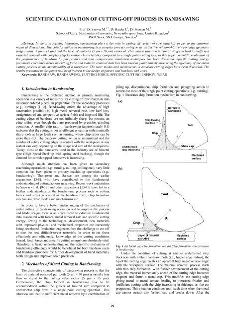
pil<strong>in</strong>g up, discont<strong>in</strong>uous chip formation and plough<strong>in</strong>g action <strong>in</strong><br />
contrast to most <strong>of</strong> the s<strong>in</strong>gle po<strong>in</strong>t <strong>cutt<strong>in</strong>g</strong> operations (e.g., turn<strong>in</strong>g).<br />
Fig. 1 illustrates chip formation mechanism <strong>in</strong> bandsaw<strong>in</strong>g.<br />
(a)<br />
(b)<br />
Fig. 1 (a) Metal cap chip formation and (b) Chip formation with extrusion<br />
<strong>in</strong> bandsaw<strong>in</strong>g.<br />
Under the condition <strong>of</strong> <strong>cutt<strong>in</strong>g</strong> at smaller undeformed chip<br />
thickness with a blunt bandsaw tooth (i.e., higher edge radius), the<br />
tip <strong>of</strong> the <strong>cutt<strong>in</strong>g</strong> edge creates an apparent high negative rake angle<br />
with the workpiece surface. The material removal <strong>process</strong> starts<br />
with th<strong>in</strong> chip formation. With further advancement <strong>of</strong> the <strong>cutt<strong>in</strong>g</strong><br />
edge, the material immediately ahead <strong>of</strong> the <strong>cutt<strong>in</strong>g</strong> edge becomes<br />
stagnant and forms a metal cap. This modifies the <strong>cutt<strong>in</strong>g</strong> edge<br />
giv<strong>in</strong>g metal to metal contact lead<strong>in</strong>g to <strong>in</strong>creased friction and<br />
<strong>in</strong>efficient <strong>cutt<strong>in</strong>g</strong> with the chip <strong>in</strong>creas<strong>in</strong>g <strong>in</strong> thickness as the cut<br />
progresses. This situation cont<strong>in</strong>ues until such time when the metal<br />
cap cannot susta<strong>in</strong> any further load and breaks down. After the
eakdown <strong>of</strong> the metal cap, the chip starts to flow aga<strong>in</strong> with a<br />
layer <strong>of</strong> material <strong>in</strong> front <strong>of</strong> the tool, extrud<strong>in</strong>g workpiece material<br />
to build a new metal cap. Similar to s<strong>in</strong>gle po<strong>in</strong>t <strong>cutt<strong>in</strong>g</strong>, chips are<br />
also produced by shear type deformation dur<strong>in</strong>g bandsaw<strong>in</strong>g. Chips<br />
could vary <strong>in</strong> size, shape and thickness. Cont<strong>in</strong>uous chips are<br />
produced when <strong>cutt<strong>in</strong>g</strong> s<strong>of</strong>t material with bandsaw teeth hav<strong>in</strong>g<br />
small edge radius (i.e., at the new condition <strong>of</strong> the tooth) compared<br />
to the depth <strong>of</strong> cut. Shorter and lumpy chips are formed by a<br />
comb<strong>in</strong>ation <strong>of</strong> shear<strong>in</strong>g and plough<strong>in</strong>g when the edge radius is<br />
higher than the undeformed chip thickness.<br />
Fig. 2 presents a snapshot <strong>of</strong> the chip formation <strong>process</strong> at the<br />
extreme <strong>cutt<strong>in</strong>g</strong> edge <strong>of</strong> a bandsaw tooth taken with a high speed<br />
camera. At the beg<strong>in</strong>n<strong>in</strong>g th<strong>in</strong> uniform chip is formed as the<br />
bandsaw tooth advances along the workpiece surface with a certa<strong>in</strong><br />
depth <strong>of</strong> cut. The workpiece material <strong>in</strong> front <strong>of</strong> the <strong>cutt<strong>in</strong>g</strong> edge is<br />
subsequently compressed and the chip thickness starts to <strong>in</strong>crease.<br />
With further advancement <strong>of</strong> the bandsaw tooth, the workpiece<br />
material cont<strong>in</strong>ues to build up until a lump is formed. Once the<br />
lump is fully formed the same <strong>process</strong> repeats aga<strong>in</strong> and aga<strong>in</strong>.<br />
Chip<br />
Workpiece<br />
Bandsaw<br />
tooth tip<br />
Fig. 2 Snapshots <strong>of</strong> chip formation <strong>in</strong> bandsaw<strong>in</strong>g as observed <strong>in</strong> High<br />
Speed Photography (bimetal bandsaw tooth mach<strong>in</strong><strong>in</strong>g steel workpiece).<br />
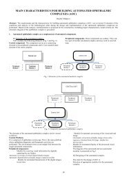
3. Scientific Evaluation <strong>of</strong> Bandsaw<strong>in</strong>g Process<br />
3.1. Full Product Test<strong>in</strong>g<br />
Traditionally, <strong>in</strong> order to evaluate the performance <strong>of</strong> bandsaw<br />
products it is necessary to carry out full-scale bandsaw tests, <strong>cutt<strong>in</strong>g</strong><br />
a large number <strong>of</strong> sections <strong>of</strong> workpiece. Fig. 3 shows a fully<br />
<strong>in</strong>strumented vertical feed bandsaw mach<strong>in</strong>e (NC controlled,<br />
Behr<strong>in</strong>ger HBP650/850A/CNC) and a schematic diagram <strong>of</strong> <strong>cutt<strong>in</strong>g</strong><br />
and feed directions dur<strong>in</strong>g bandsaw<strong>in</strong>g. There are only two different<br />
parameters constitut<strong>in</strong>g the <strong>cutt<strong>in</strong>g</strong> data <strong>in</strong> bandsaw<strong>in</strong>g, namely<br />
<strong>cutt<strong>in</strong>g</strong> speed and feed rate.<br />
(a)<br />
(b)<br />
FP<br />
Feed<br />
rate<br />
Workpiece<br />
FP<br />
Fv<br />
Cutt<strong>in</strong>g<br />
speed<br />
Fig. 3 (a) Experimental set-up used for bandsaw<strong>in</strong>g tests and (b) schematic<br />
diagram <strong>of</strong> thrust force (Fp) and <strong>cutt<strong>in</strong>g</strong> force (Fv) act<strong>in</strong>g on the bandsaw.<br />
The feed rate along with the choice <strong>of</strong> tooth pitch and <strong>cutt<strong>in</strong>g</strong><br />
speed decides the depth <strong>of</strong> cut per <strong>cutt<strong>in</strong>g</strong> edge. The depth <strong>of</strong> cut<br />
affects the contact conditions at the edge, thereby hav<strong>in</strong>g an effect<br />
on the thrust and <strong>cutt<strong>in</strong>g</strong> forces. The <strong>cutt<strong>in</strong>g</strong> speed governs the<br />
30<br />
slid<strong>in</strong>g speed at the <strong>cutt<strong>in</strong>g</strong> edge and has a direct effect on<br />
temperature produced <strong>in</strong> <strong>cutt<strong>in</strong>g</strong>. The appropriate selection <strong>of</strong><br />
<strong>cutt<strong>in</strong>g</strong> conditions is essential, as different workpiece materials<br />
require different sett<strong>in</strong>gs. Cutt<strong>in</strong>g force and thrust force components<br />
are measured dur<strong>in</strong>g the bandsaw<strong>in</strong>g tests us<strong>in</strong>g a 3-axis Kistler<br />
dynamometer. Fig. 4 shows the development <strong>of</strong> feed and <strong>cutt<strong>in</strong>g</strong><br />
forces dur<strong>in</strong>g the life <strong>of</strong> one bandsaw blade. The blade lasted for<br />
950 cuts. The rapid <strong>in</strong>crease <strong>of</strong> the <strong>cutt<strong>in</strong>g</strong> forces dur<strong>in</strong>g the first<br />
few hundred cuts <strong>in</strong>dicates a more rapid <strong>in</strong>itial wear rate. This is<br />
followed by steady-state wear (secondary stage, ma<strong>in</strong> stage) until<br />
the <strong>cutt<strong>in</strong>g</strong> force component reaches a f<strong>in</strong>al accelerated stage <strong>of</strong><br />
wear.<br />
Force (N)<br />
1600<br />
1400<br />
1200<br />
1000<br />
800<br />
600<br />
400<br />
200<br />
0<br />
Thrust force<br />
Cutt<strong>in</strong>g force<br />
Cutt<strong>in</strong>g force<br />
Thrust force<br />
Bandsaw blade sample 3<br />
120 mm Ball-bear<strong>in</strong>g steel bar<br />
Tooth shape PSG 2/3<br />
Cutt<strong>in</strong>g speed 80 m/m<strong>in</strong><br />
Feed rate 32 mm/m<strong>in</strong><br />
Average feed per tooth 4.7 micrometers<br />
0 100 200 300 400 500 600 700 800 900 1000<br />
Number <strong>of</strong> sections cut<br />
Fig. 4 Increase <strong>in</strong> force components with wear <strong>of</strong> the bandsaw blade <strong>in</strong> full<br />
product test<strong>in</strong>g.<br />
Specific <strong>cutt<strong>in</strong>g</strong> energy (Esp) has been <strong>in</strong>troduced as a parameter<br />
to quantitatively measure the efficiency <strong>of</strong> the bandsaw<strong>in</strong>g <strong>process</strong>.<br />
Esp is a measure <strong>of</strong> the energy required to remove a unit volume <strong>of</strong><br />
workpiece material. Esp can assess products and <strong>process</strong> based on<br />
<strong>scientific</strong> values associated with both <strong>cutt<strong>in</strong>g</strong> forces (i.e., power)<br />
and material removal rate (feed, depth <strong>of</strong> cut and speed). Moreover,<br />
Esp can be used to correlate various stages <strong>of</strong> tool wear to the<br />
performance <strong>of</strong> the bandsaw teeth, as it is more sensitive to low<br />
depths <strong>of</strong> cut, which is the case <strong>in</strong> bandsaw<strong>in</strong>g operation [16]. Fig. 5<br />
shows the variation <strong>of</strong> Esp with the number <strong>of</strong> cuts produced when<br />
<strong>cutt<strong>in</strong>g</strong> Ballbear<strong>in</strong>g steel with three different bandsaw blades. For<br />
all three bandsaws, Esp values for the sharp teeth are found to be<br />
approximately 5 GJ/m 3 , which become doubled as the bandsaws<br />
start <strong>cutt<strong>in</strong>g</strong> out <strong>of</strong> square cut (failure mode that <strong>in</strong>dicates the end <strong>of</strong><br />
bandsaw life). The variation <strong>of</strong> Esp values also show the similar<br />
trend as the <strong>cutt<strong>in</strong>g</strong> forces.<br />
ESP (GJ/m3)<br />
12<br />
10<br />
8<br />
6<br />
4<br />
2<br />
0<br />
Band 1<br />
Band 2<br />
Band 3<br />
Average ESP<br />
Chip after<br />
1 section<br />
cut<br />
Chip after<br />
712 sections<br />
cut<br />
Chip ratio: 0.1-0.15<br />
Workpiece: 120 mm Ball-bear<strong>in</strong>g steel bar<br />
Tooth shape PSG 2/3<br />
Cutt<strong>in</strong>g speed 80 m/m<strong>in</strong><br />
Feed rate 32 mm/m<strong>in</strong><br />
Average feed per tooth 4.7 micrometers<br />
Calculated actual feed per tooth 14 micrometers<br />
0 100 200 300 400 500 600 700 800 900 1000<br />
Number <strong>of</strong> sections cut<br />
Fig. 5 Specific <strong>cutt<strong>in</strong>g</strong> energy (Esp) dur<strong>in</strong>g full bandsaw wear tests <strong>in</strong><br />
Ballbear<strong>in</strong>g steel workpiece.<br />
It is <strong>in</strong>terest<strong>in</strong>g to note that all <strong>of</strong> the bandsaw samples have<br />
failed at approximately same level <strong>of</strong> Esp (~10 GJ/m 3 ). The variation<br />
<strong>in</strong> the bandsaw life could be expla<strong>in</strong>ed by the variation <strong>of</strong> bandsaw<br />
tooth geometry (e.g., back to tip height, tooth tip condition, etc.), set<br />
geometry (e.g., set magnitude, set balance, set angle, etc.) and<br />
mechanical properties (e.g., hardness, toughness, etc.) <strong>in</strong><br />
approximately 800 teeth <strong>of</strong> a particular band loop.
The other measurements and <strong>in</strong>vestigations such as wear land<br />
area, edge geometry, surface characteristics <strong>of</strong> cut-<strong>of</strong>f workpieces<br />
(wav<strong>in</strong>ess), chip characteristics, out <strong>of</strong> square <strong>cutt<strong>in</strong>g</strong>, set width etc.<br />
need to be carried out to fully understand the bandsaw <strong>cutt<strong>in</strong>g</strong><br />
characteristics. The full-scale test<strong>in</strong>g activities can take several<br />
months <strong>of</strong> laboratory work.<br />
3.2. S<strong>in</strong>gle Tooth Time Compression Test<strong>in</strong>g<br />
The bandsaw<strong>in</strong>g community faces one <strong>of</strong> the primary problems<br />
<strong>in</strong> quickly evaluat<strong>in</strong>g metal bandsaws <strong>in</strong> order to develop newer<br />
variants, compris<strong>in</strong>g <strong>of</strong> new saw tooth materials, their heat<br />
treatment, or different tooth forms and quality. Furthermore, there<br />
are no simple ways <strong>of</strong> quantify<strong>in</strong>g and evaluat<strong>in</strong>g the performance<br />
and life <strong>of</strong> these bands dur<strong>in</strong>g saw<strong>in</strong>g. Normally the time per cut as<br />
well as monitor<strong>in</strong>g <strong>in</strong>direct parameters such as <strong>in</strong>crease <strong>in</strong> <strong>cutt<strong>in</strong>g</strong><br />
forces, or the amount <strong>of</strong> run-out <strong>of</strong> the saw kerf from the vertical<br />
plane are <strong>of</strong>ten used as performance criteria <strong>in</strong> full product test<strong>in</strong>g.<br />
This only gives global data, which is difficult to apply to <strong>in</strong>dividual<br />
teeth. In addition, it is costly, complex and time-consum<strong>in</strong>g to test<br />
the wear <strong>of</strong> full bandsaw products <strong>in</strong> full-scale bandsaw mach<strong>in</strong>es.<br />
Therefore, it is desirable to f<strong>in</strong>d a bandsaw simulation test or timecompression<br />
test that reduces the cost and the time consumption<br />
when perform<strong>in</strong>g bandsaw test<strong>in</strong>g or adds further possibilities <strong>of</strong><br />
<strong>in</strong>vestigat<strong>in</strong>g the <strong>cutt<strong>in</strong>g</strong> action. A time compression test also needs<br />
to be fully representative <strong>of</strong> the ord<strong>in</strong>ary bandsaw product test<strong>in</strong>g<br />
and give the fundamental data required for optimis<strong>in</strong>g the <strong>cutt<strong>in</strong>g</strong><br />
conditions. The results that are produced need to be mean<strong>in</strong>gful <strong>in</strong><br />
order to replace the full bandsaw test<strong>in</strong>g.<br />
S<strong>in</strong>gle tooth time compression technique uses s<strong>in</strong>gle bandsaw<br />
tooth to simulate the bandsaw<strong>in</strong>g <strong>process</strong> [4, 5, 17]. Intermittent<br />
<strong>cutt<strong>in</strong>g</strong> us<strong>in</strong>g the s<strong>in</strong>gle tooth simulation method for different depths<br />
<strong>of</strong> cut (2μm to 50μm) proved successful <strong>in</strong> the study <strong>of</strong> specific<br />
<strong>cutt<strong>in</strong>g</strong> energy and the <strong>cutt<strong>in</strong>g</strong> forces. The <strong>cutt<strong>in</strong>g</strong> depth per tooth<br />
achieved was very similar to that found <strong>in</strong> actual bandsaw<strong>in</strong>g<br />
<strong>process</strong>. The large number <strong>of</strong> results obta<strong>in</strong>ed for different depths <strong>of</strong><br />
cut per tooth show that the test<strong>in</strong>g method adopted can be used to<br />
simulate an actual bandsaw<strong>in</strong>g <strong>process</strong>. Cutt<strong>in</strong>g force components<br />
<strong>of</strong> the time compression test (Fig. 6) give results, which are very<br />
closely related to the full product results. Hence, the time<br />
compression test can be effectively used with reliability <strong>in</strong><br />
establish<strong>in</strong>g useful data at a significantly reduced time.<br />
Force (N)<br />
140<br />
120<br />
100<br />
80<br />
60<br />
40<br />
20<br />
0<br />
Method: Time compression test Test: Ball-bear<strong>in</strong>g steel 5<br />
Workpiece: 94 mm width Radius <strong>of</strong> cut: 170 mm +/-6%<br />
Cutt<strong>in</strong>g speed: 80 m/m<strong>in</strong> +/-6% Feed per cut: 14 micrometers<br />
Cutt<strong>in</strong>g fluid rate: 1.3 ml/s<br />
Fp<br />
Fv<br />
Fside<br />
Side force<br />
Cutt<strong>in</strong>g force<br />
Thrust force<br />
0 200 400 600 800 1000 1200 1400<br />
Number <strong>of</strong> cuts<br />
Fig. 6 Increase <strong>in</strong> force components with wear <strong>of</strong> the bandsaw tooth <strong>in</strong> time<br />
compression test.<br />
The variation <strong>in</strong> specific <strong>cutt<strong>in</strong>g</strong> energy aga<strong>in</strong>st depth <strong>of</strong> cut per<br />
tooth gives a typical exponential curve (Fig. 7). The effect <strong>of</strong> the<br />
edge radius <strong>of</strong> the <strong>cutt<strong>in</strong>g</strong> tool (saw tooth) is significant at lower<br />
depths <strong>of</strong> cut, giv<strong>in</strong>g an <strong>in</strong>efficient <strong>cutt<strong>in</strong>g</strong> action (higher specific<br />
<strong>cutt<strong>in</strong>g</strong> energy). When the depth <strong>of</strong> cut per tooth is <strong>in</strong>creased, the<br />
edge radius effect decreases result<strong>in</strong>g <strong>in</strong> <strong>in</strong>creased efficiency (lower<br />
specific <strong>cutt<strong>in</strong>g</strong> energy). The specific <strong>cutt<strong>in</strong>g</strong> energy reaches a<br />
steady state at 2 GJ/m 3 .<br />
31<br />
Specific Cutt<strong>in</strong>g Energy (GJ/m3)<br />
14<br />
12<br />
10<br />
8<br />
6<br />
4<br />
2<br />
0<br />
0 10 20 30 40 50 60<br />
Depth <strong>of</strong> cut per tooth (m)<br />
Fig. 7 Influence <strong>of</strong> depth <strong>of</strong> cut on specific <strong>cutt<strong>in</strong>g</strong> Energy dur<strong>in</strong>g<br />
performance tests (S<strong>in</strong>gle tooth simulation test).<br />
4. Failure Modes and Mechanisms <strong>in</strong> Bandsaw<strong>in</strong>g<br />
4.1. Failure Modes<br />
In general, bandsaws fail due to one or a comb<strong>in</strong>ation <strong>of</strong> the<br />
follow<strong>in</strong>gs: Out <strong>of</strong> square <strong>cutt<strong>in</strong>g</strong>, premature tooth failure, tooth<br />
wear or fatigue <strong>of</strong> back<strong>in</strong>g metal as shown <strong>in</strong> Fig. 8 [18]. Out <strong>of</strong><br />
square <strong>cutt<strong>in</strong>g</strong> is the most important reason for bimetal bandsaw<br />
failure. Out <strong>of</strong> square cut is caused due to the lateral displacement<br />
<strong>of</strong> band on a side. This could be related to <strong>in</strong>stability <strong>in</strong> the band<br />
due to higher applied thrust force or unsymmetrical wear <strong>in</strong> the<br />
teeth. An <strong>in</strong>correct choice <strong>of</strong> <strong>cutt<strong>in</strong>g</strong> data can result premature tooth<br />
failure due to the application <strong>of</strong> large forces. When the total wear <strong>in</strong><br />
the bandsaw teeth researches a critical value, a change <strong>in</strong> tooth<br />
geometry takes place (i.e., edge blunt<strong>in</strong>g). This can gradually lead<br />
to a higher <strong>cutt<strong>in</strong>g</strong> force, ultimately stopp<strong>in</strong>g the bandsaw from<br />
<strong>cutt<strong>in</strong>g</strong> any further, if the bandsaw has not failed <strong>in</strong> another mode at<br />
that po<strong>in</strong>t. The development <strong>of</strong> alternat<strong>in</strong>g stresses <strong>in</strong> the bandsaw<br />
loop from bend<strong>in</strong>g and twist<strong>in</strong>g can generate fatigue cracks while<br />
the loop is circulat<strong>in</strong>g around wheels and guides. These cracks grow<br />
until the band loop is broken by fatigue failure.<br />
(a) (b)<br />
(c) (d)<br />
Fig. 8 Bandsaw failure modes: (a) out <strong>of</strong> square cut (b) tooth failure (c)<br />
tooth wear and (d) fatigue failure.<br />
4.2. Wear Modes<br />
The wear modes <strong>in</strong> bandsaw tooth depend on the work-piece<br />
material chosen, type <strong>of</strong> bandsaw tool material and the selection <strong>of</strong><br />
<strong>cutt<strong>in</strong>g</strong> conditions. In general, the pr<strong>in</strong>cipal wear modes <strong>in</strong> any<br />
bandsaw tooth can be identified as flank wear, corner wear, rake<br />
face wear and edge round<strong>in</strong>g as shown <strong>in</strong> Fig. 9 [10-12]. Bandsaw<br />
teeth are worn <strong>in</strong> such a way that wear flat is produced at the tip <strong>of</strong><br />
each tooth and the outer corners <strong>of</strong> the teeth are rounded. Rake face<br />
wear is generally not as severe as the flank wear. However, rake<br />
face wear can also contribute to a local change <strong>in</strong> <strong>cutt<strong>in</strong>g</strong> edge<br />
geometry. The change <strong>in</strong> edge geometry (edge round<strong>in</strong>g) will result<br />
<strong>in</strong>efficient chip formation due to an <strong>in</strong>crease <strong>in</strong> the ratio <strong>of</strong> edge<br />
radius to depth <strong>of</strong> cut.
(a) (b)<br />
(c) (d)<br />
Fig. 9 Bandsaw wear modes: (a) flank wear (b) corner wear (c) rake face<br />
wear and (d) blunt<strong>in</strong>g or edge radius.<br />
4.3. Wear Mechanisms<br />
In High Speed Steel (HSS) bimetal bandsaw tooth, flank and<br />
corner wear are developed due to the abrasive action between the<br />
tooth and the mach<strong>in</strong>ed workpiece with small to large amount <strong>of</strong><br />
adhesive wear depend<strong>in</strong>g the properties <strong>of</strong> the workpiece materials<br />
[10, 11]. Metal cap or built-up edge is formed at the tooth edge and<br />
this could affect the <strong>cutt<strong>in</strong>g</strong> condition and tooth wear (Fig. 10).<br />
Plastic deformation, micro-chipp<strong>in</strong>g and thermal fatigue can also be<br />
observed <strong>in</strong> some cases.<br />
(a) (b)<br />
Metal cap/<br />
BUE<br />
Rake<br />
face<br />
Rake face<br />
wear<br />
Flank<br />
wear<br />
Clearance<br />
face<br />
Abrasive<br />
wear<br />
Worn flank<br />
Adhered<br />
workpiece<br />
material<br />
Fig. 10 Wear mechanisms <strong>in</strong> bandsaw teeth when <strong>cutt<strong>in</strong>g</strong> (a) ballbear<strong>in</strong>g<br />
steel and (b) sta<strong>in</strong>less steel.<br />
5. Conclud<strong>in</strong>g Remarks<br />
Although bandsaw<strong>in</strong>g <strong>process</strong> has been around for many years,<br />
very little research effort has been devoted to understand the<br />
mechanics <strong>of</strong> material removal, associated wear modes and<br />
mechanisms and <strong>scientific</strong> <strong>evaluation</strong> <strong>of</strong> the bandsaw products.<br />
Unlike other multipo<strong>in</strong>t <strong>cutt<strong>in</strong>g</strong> tools (e.g., mill<strong>in</strong>g) the material<br />
removal <strong>process</strong> together with the wear and failure modes <strong>in</strong><br />
bandsaw is far more complex. Although the method <strong>of</strong> manufacture<br />
<strong>of</strong> the <strong>cutt<strong>in</strong>g</strong> edges have been improved from mill<strong>in</strong>g to gr<strong>in</strong>d<strong>in</strong>g<br />
(giv<strong>in</strong>g more uniformity and accuracy <strong>of</strong> <strong>cutt<strong>in</strong>g</strong> edges), the layer <strong>of</strong><br />
material removed is still very small. This causes a complex<br />
comb<strong>in</strong>ation <strong>of</strong> chip formation mechanisms (i.e., cont<strong>in</strong>uous chip,<br />
plough<strong>in</strong>g and fragmented chip). Flank and corner wear usually<br />
caused by abrasion and adhesion can alter the edge geometry (e.g.,<br />
edge radius) and affect the chip formation mechanism.<br />
Traditionally the performance <strong>of</strong> bandsaw is evaluated through<br />
full scale life test<strong>in</strong>g, which is complex and time consum<strong>in</strong>g. S<strong>in</strong>gle<br />
tooth time compression technique can be successfully employed to<br />
<strong>scientific</strong>ally evaluate the bandsaw product <strong>in</strong> a representative way.<br />
Specific <strong>cutt<strong>in</strong>g</strong> energy (Esp) is an excellent parameter for<br />
assess<strong>in</strong>g the tool/workpiece comb<strong>in</strong>ation efficiency. The high<br />
value <strong>of</strong> Esp (~10 GJ/m 3 ) <strong>in</strong>dicates that bandsaw<strong>in</strong>g is not as<br />
efficient as a s<strong>in</strong>gle-po<strong>in</strong>t turn<strong>in</strong>g tool (~1.0-1.5 GJ/m 3 ) where the<br />
chip is free to flow and the layer <strong>of</strong> metal removed is larger. The Esp<br />
32<br />
also turns out to be a useful parameter to relate various stages <strong>of</strong><br />
wear to the bandsaw performance.<br />
6. Reference<br />
[1] Owen, J.V. Bandsaws jo<strong>in</strong> the ma<strong>in</strong>stream-Manufactur<strong>in</strong>g<br />
Eng<strong>in</strong>eer<strong>in</strong>g, 1997, 28-39<br />
[2] Hellbergh, H, M. Persson, M. Sarwar Developments <strong>in</strong> High<br />
Speed Steel (HSS) <strong>cutt<strong>in</strong>g</strong> edges for band saw<strong>in</strong>g applications<strong>in</strong>:<br />
Proceed<strong>in</strong>gs <strong>of</strong> the HSS forum conference, January 20-21,<br />
2009, Aachen, Germany<br />
[3] Thompson, P.J. Factors <strong>in</strong>fluenc<strong>in</strong>g the saw<strong>in</strong>g rate <strong>of</strong> hard<br />
ductile metals dur<strong>in</strong>g power hacksaw and bandsaw operations-<br />
Metals Technology, 1974, 437-443<br />
[4] Sarwar, M., P.J. Thompson Simulation <strong>of</strong> the <strong>cutt<strong>in</strong>g</strong> action <strong>of</strong><br />
a s<strong>in</strong>gle hacksaw blade tooth-The Production Eng<strong>in</strong>eer, 1974,<br />
195-198<br />
[5] Sarwar, M., P. J. Thompson Cutt<strong>in</strong>g action <strong>of</strong> blunt tools-<strong>in</strong>:<br />
Proceed<strong>in</strong>gs <strong>of</strong> the International Conference on Mach<strong>in</strong>e tool<br />
design and research, 1981, Manchester, UK, 295–303<br />
[6] Sarwar, M The mechanics <strong>of</strong> power hacksaw<strong>in</strong>g and the <strong>cutt<strong>in</strong>g</strong><br />
action <strong>of</strong> blunt tools-Ph.D. thesis at Dept. <strong>of</strong> Mech. and Prod.<br />
Eng., Sheffield City Polytechnic, April 1982<br />
[7] Sarwar, M., S.R. Bradbury, M. D<strong>in</strong>sdale An approach to<br />
computer aided bandsaw teeth test<strong>in</strong>g and design-<strong>in</strong>:<br />
Proceed<strong>in</strong>gs <strong>of</strong> 4 th National Conference on Production<br />
Research, Sept. 1988, Sheffield, UK<br />
[8] Archer, P.M., S.R. Bradbury, M. Sarwar Evaluation <strong>of</strong><br />
performance and wear characteristics <strong>of</strong> bandsaw blades-<strong>in</strong>:<br />
Proceed<strong>in</strong>gs <strong>of</strong> the 5 th National Conference on Production<br />
research, Huddersfield Polytechnic, Huddersfield, UK, 1989,<br />
pp. 443–451.<br />
[9] Sarwar, M., M. Persson, H. Hellbergh Chip formation<br />
mechanisms <strong>in</strong> bandsaw metal <strong>cutt<strong>in</strong>g</strong>-<strong>in</strong>: Proceed<strong>in</strong>gs <strong>of</strong> the<br />
18 th International Conference on Production research, 2005,<br />
Salerno, Italy<br />
[10] Sarwar, M., M. Persson, H. Hellbergh Wear and failure <strong>in</strong> the<br />
bandsaw<strong>in</strong>g operation when <strong>cutt<strong>in</strong>g</strong> ball-bear<strong>in</strong>g steel-Wear,<br />
259, 2005, 1144–1150<br />
[11] Sarwar, M., M. Persson, H. Hellbergh Wear <strong>of</strong> the <strong>cutt<strong>in</strong>g</strong> edge<br />
<strong>in</strong> the bandsaw<strong>in</strong>g operation when <strong>cutt<strong>in</strong>g</strong> austenitic 17-7<br />
sta<strong>in</strong>less steel-Wear, 263, 2007, 1438-1441.<br />
[12] Sarwar, M., M. Persson, H. Hellbergh, J. Haider Forces, wear<br />
modes and mechanisms <strong>in</strong> bandsaw<strong>in</strong>g steel workpieces-<br />
IMechE Proceed<strong>in</strong>gs Part B: Journal <strong>of</strong> Eng<strong>in</strong>eer<strong>in</strong>g<br />
Manufacture, 224, 2010, 1655-16662<br />
[13] Andersson, C., M. T. Andersson, J. -E. Ståhl Bandsaw<strong>in</strong>g. Part<br />
I: <strong>cutt<strong>in</strong>g</strong> force model <strong>in</strong>clud<strong>in</strong>g effects <strong>of</strong> positional errors,<br />
tool dynamics and wear-International Journal <strong>of</strong> Mach<strong>in</strong>e<br />
Tools and Manufacture, 41, 2001, 227-236<br />
[14] Andersson, C., J.-E. Ståhl, H. Hellbergh Bandsaw<strong>in</strong>g. Part II:<br />
detect<strong>in</strong>g positional errors, tool dynamics and wear by <strong>cutt<strong>in</strong>g</strong><br />
force measurement-International Journal <strong>of</strong> Mach<strong>in</strong>e Tools and<br />
Manufacture, 41, 2001, 237–253<br />
[15] Ahmad, M.M., B. Hogan, E. Goode Effect <strong>of</strong> mach<strong>in</strong><strong>in</strong>g<br />
parameters and workpiece shape on a bandsaw<strong>in</strong>g <strong>process</strong>-<br />
International Journal <strong>of</strong> Mach<strong>in</strong>e Tools and Manufacture, 29,<br />
1989, 173–183<br />
[16] Sarwar, M., M. Persson, H. Hellbergh, J. Haider Measurement<br />
<strong>of</strong> specific <strong>cutt<strong>in</strong>g</strong> energy for evaluat<strong>in</strong>g the efficiency <strong>of</strong><br />
bandsaw<strong>in</strong>g different workpiece materials-International Journal<br />
<strong>of</strong> Mach<strong>in</strong>e Tools and Manufacture, 49, 2009, 958-965<br />
[17] Sarwar, M., H. Hellbergh, A.R. Dorais<strong>in</strong>gam, M. Persson<br />
Simulation <strong>of</strong> the <strong>in</strong>termittent <strong>cutt<strong>in</strong>g</strong> action <strong>of</strong> a bandsaw<br />
blade-<strong>in</strong>: Proceed<strong>in</strong>gs <strong>of</strong> the 12 th International Conference on<br />
Flexible Automation and Intelligent Manufactur<strong>in</strong>g, 2002,<br />
Dresden, Germany<br />
[18] Sarwar, M., M. Persson, H. Hellbergh, A. R. Dorais<strong>in</strong>gam<br />
Wear and failure <strong>of</strong> high-speed steel bimetal bandsaws-<strong>in</strong>:<br />
Proceed<strong>in</strong>gs <strong>of</strong> the 14 th International Conference on Flexible<br />
Automation & Intelligent Manufactur<strong>in</strong>g, 12–14 July 2004,<br />
Toronto, Canada, 866–873