CHARACTERIZATION OF A BIOMASS MILLING PILOT ... - circe
CHARACTERIZATION OF A BIOMASS MILLING PILOT ... - circe
CHARACTERIZATION OF A BIOMASS MILLING PILOT ... - circe

Create successful ePaper yourself
Turn your PDF publications into a flip-book with our unique Google optimized e-Paper software.
<strong>CHARACTERIZATION</strong> <strong>OF</strong> A <strong>BIOMASS</strong> <strong>MILLING</strong> <strong>PILOT</strong> PLANT<br />
M. Gil*, I. Ramos, I. Arauzo, J. Román<br />
CIRCE, Centre of Research for Energy Resources and Consumption<br />
C/ Maria de Luna, 3 50018, Zaragoza, Spain<br />
*Corresponding author: miguelgc@unizar.es; tel: +34 976762562; Fax:+34 976732078<br />
ABSTRACT: Biomass milling pretreatment is a necessary process to adapt particle size to the requirements of<br />
different energy conversion technologies. The objectives of biomass milling experimental tests are to optimize the<br />
high energy requirement and to characterize the different milling variables to produce a high quality solid fuel and to<br />
decrease the electrical consumptions.<br />
The characterization process of milling facility at CIRCE cofiring laboratory includes the analysis, instrumentation,<br />
control and data acquisition of the main factors that have an influence in size distribution and shape of milled<br />
particles, in drying and densification effects, and in energy requirement of the whole process. The facility is fully<br />
instrumented and a control and data acquisition system has been installed. These features will allow to obtain on line<br />
information about the working conditions and energy requirements in mills and pneumatic conveying system. Also<br />
several sample points has been installed to take a representative sample of milled biomass. A study has been<br />
developed to assess the feasibility of isokinetic sampling methods in pneumatic conveying ducts to obtain a<br />
representative sample of milled biomass and to analyse and characterize the influence of the grinding variables in the<br />
milled product.<br />
Keywords: characterization, pretreatment, sampling, control systems.<br />
1 INTRODUCTION<br />
Biomass is one of renewable energy with highest<br />
potential and implantation capacity due to the great<br />
variety of biomass species and the wide possibilities of<br />
energetic transformation. Biomass energy conversion<br />
technologies include solids combustion in power stations<br />
to electricity generation (cofiring or biomass exclusive<br />
combustion in pulverized or grate boilers), in district<br />
heating generation or by combustion of densified biomass<br />
solids in domestic boilers. Other technologies transform<br />
the biomass to liquid fuels, mainly for automobile<br />
engines, or to gaseous fuels for later combustion.<br />
Most of these technologies require biomass<br />
pretreatment to adequate the physic and chemical<br />
properties to the final transformation requirements. One<br />
of these pretreatment is size reduction. It is considered<br />
grinding or milling when the final particle size is lower<br />
than 80 mm [1]. Milling objective is to provide a milled<br />
product, whose characteristics satisfy the requirements,<br />
with the lowest possible milling energy requirements.<br />
Usually, biomass is supplied with a previous chipping or<br />
crushing pretreatment. The size reduction results in an<br />
increase of the particle surface-to-volume ratio (particle<br />
specific surface) and, subsequently, in an increase of the<br />
outer surface that will promote further treatments or<br />
chemical reactions. This size reduction is required to<br />
optimize the combustion of biomass in pulverized-fuel<br />
burners or the production of high-density fuels [2-4] or<br />
bio-ethanol [4-6]. However, the milling process brings<br />
along remarkable energy consumptions, within the range<br />
0.5-10% of biomass heating value and depending on<br />
multiple factors [7]. The decrease of the related costs<br />
could represent the key step to warrant the feasibility for<br />
using biomass as the raw material for all those processes.<br />
Aside from the particle size reduction, the milling<br />
process includes several advantages that strengthen the<br />
added value of the product:<br />
Easy sorting of material by size through<br />
separation<br />
Significant biomass bulk density increase. A<br />
reduction size stage is necessary to carry out<br />
intensive densification process as briquetting or<br />
pelletezing [8-10]<br />
Easy handling and drying of bulk material<br />
Reduced transportation costs<br />
Drying effect during milling process [8-10]<br />
Physical properties homogenization of milled<br />
material.<br />
Increase the efficiency energetic conversion<br />
Although publications in this subject are scarce,<br />
several studies show the influence of different variables<br />
in milling energy requirement. These variables can be<br />
classified in input and output biomass characteristics and<br />
operational parameters of comminution process. Physical<br />
and mechanical properties of biomass species and<br />
varieties are very important to select the appropriate type<br />
of mill. Conditions of supply biomass as initial particle<br />
size, moisture content or impurities play an essential role.<br />
In modelling of pulverization process, three aspects are<br />
fundamental to achieve the established goals. Facility<br />
design requires: a suitable selection of type of mill and<br />
the appropriate combinations between mills and auxiliary<br />
equipments. Mills can be arranged in series or in parallel,<br />
with one or more number of mill stages by production<br />
line, batch or continuous milling and the possibility to<br />
include previous, intermediate or later particle size<br />
classifier equipment. Finally, operational parameters<br />
should be studied to decrease the global operational costs<br />
of pretreatment.<br />
Identification and study of different physical process<br />
carried out during milling may allow to determinate the<br />
influential variables. Instrumentation and automation<br />
permit its variation, registration, acquisition and<br />
visualization to evaluate the influence on enumerated<br />
objectives.<br />
By means of the control and monitoring systems of<br />
the variable, it is possible to regulate automatically the<br />
main principal operational parameters, as mills angular<br />
speed, air mass flow in pneumatic conveying and<br />
biomass feed rate to the mills. The system presents other<br />
advantages as the signals treatments, visualization and<br />
observation of variables trends on line. With this<br />
information it is possible to take decisions during test<br />
based on the actual system state.<br />
Process characterization is completed by several
milled biomass characteristics analysis: particle size<br />
distribution, moisture content, bulk density, particle<br />
shape factor and chemical composition as function<br />
particle size. The properties variations permit to assess<br />
the influence of the parameters mentioned in final milled<br />
material.<br />
2 <strong>BIOMASS</strong> <strong>MILLING</strong> <strong>PILOT</strong> PLANT<br />
Experimental facility characterization should analyse<br />
the design and operational parameters needed to satisfy<br />
the particle size requeriment with the lowest milling<br />
energy consumption.<br />
The size requirements are fixed by the final energetic<br />
conversion technology and can be expressed by range of<br />
particle sizes, or by more specific granulometric<br />
regulations.<br />
Biomass shows a high heterogeneity in connection<br />
with inherent mechanical and physical properties, and in<br />
reception conditions (moisture content, raw particle<br />
size…). Flexibility in experimental comminution facility<br />
permit to carry out several tests varying:<br />
Type of mill<br />
Equipment combinations<br />
Operational parameters<br />
Biomass mechanical properties represent a relevant<br />
parameter to select the adequate type of mill. Biomass is<br />
mainly composed of non-brittle materials [11] in contrast<br />
with other energetic resources as coal. Several studies<br />
show three types of mills as the most appropriate for<br />
biomass milling: hammer mills, knife mills and also disc<br />
mills in specific conditions [11].<br />
Studied facility is composed of two mills: a hammer<br />
mill and duplex mill [8]. Hammer mill with horizontal<br />
axis and a drive of 11kW comprises 6 hammers arranged<br />
on 3 radial lines. Duplex mill with a drive of 4kW consist<br />
of three hammers in revolution that carry out two<br />
different milling actions: impact breakage of hammers<br />
against particles and breakage by shearing stress between<br />
the hammer, particles and a fixed element inside the<br />
milling chamber.<br />
Grinders are the main equipment in any milling<br />
facility. However, classifying equipments are<br />
incorporated to separate the particles as function their<br />
size. The classifier has operational flexibility which<br />
increases the number of possible mills configuration<br />
allowing the most suitable solid treatment.<br />
Classifying systems select those particles whose size<br />
satisfies the final requirement. Classifier can be used as a<br />
previous stage to separate the particles which satisfy the<br />
size requirement, as a final stage to guarantee the particle<br />
size of final product or as an intermediate stage to convey<br />
the coarse particle again to mill (recirculation flow).<br />
When the upper limit size is fixed, coarse particle can be<br />
eliminated or can be passed by the mill a number of times<br />
necessary to obtain the desired size. In case of lower size<br />
limit, the fine particles are eliminated of the final milled<br />
product.<br />
Milling facility also incorporates auxiliary solid<br />
handling equipment to convey the particles between the<br />
main equipments. At CIRCE milling biomass facility<br />
(e.g. Fig. 1), three different systems are installed to<br />
convey solids. First of all, a belt conveyor is used to feed<br />
the biomass to the mills. Subsequently, pneumatic<br />
conveying, composed of two fans to generate the air<br />
flow, and two equipments (cyclone and bag filter) to<br />
separate the air-particles flow, carries the pulverized<br />
biomass from mills to the final bin. Finally, coarse<br />
particle recirculation is conveyed to mills using an screw<br />
conveyor.<br />
The different combinations between hammer mill,<br />
duplex mills and screen classifier provide five milling<br />
configurations:<br />
1. Configuration A.1: hammer mill<br />
2. Configuration A.2: hammermill and screen<br />
classifier<br />
3. Configuración B.1: duplex mill<br />
4. Configuración B.2: duplex mill and screen<br />
classifier<br />
5. Configuración C: hammer mill, screen<br />
classifier and duplex mill.<br />
Experimental tests in A.1 and A.2 configurations are<br />
focused on the hammer mill analysis:<br />
A.1. Hammer mill.<br />
Particle size is fixed by the internal screen opening<br />
size. Particles pass trough the hammer mill and are<br />
directly carried by pneumatic conveying to the bin. .<br />
A.2. Hammer mill with recirculation to the same mill.<br />
Milled biomass particles in hammer mill are<br />
conveyed to the screen classifier where fines are<br />
separated from the coarse ones. Fine particles are<br />
directly transported to the bin, whereas coarse<br />
particles are conveyed again to the hammer mill<br />
until a suitable particle size is achieved. In this<br />
configuration, the goal particle size is fixed by the<br />
screen opening size in the classifier.<br />
Third and fourth configurations allow the study to be<br />
focused on duplex mill:<br />
B.1. Duplex mill.<br />
As in the A.1 configuration, particles pass trough the<br />
duplex mill before they are being transported by<br />
pneumatic conveying to the bin. Internal screen<br />
determines the final particle size.<br />
B.2. Duplex mill with recirculation to the same mill.<br />
This configuration is similar to A.2. In case finer<br />
particle sizes are needed, this configuration allows<br />
the particle flow to pass several times trough the<br />
mill until the suitable size is reached.<br />
The last configuration is focused on the combination<br />
between both mills with a screening intermediate stage:<br />
C. Hammer mill with recirculation to the duplex mill.<br />
In this configuration (e.g. Fig. 1) the milling and<br />
classifying process are the same as in A.2 configuration,<br />
except for the coarse recirculation. In this case, the coarse<br />
particles are redirected to the duplex mill. The facility<br />
allows both recirculation types.<br />
Configuration changes can be made by means of<br />
removable pneumatic conveying ducts. The combinations<br />
between configurations and internal screens allow to<br />
obtain the suitable particle size in the process.<br />
To control the equipment of the facility, an control<br />
automatic system and data acquisition have been<br />
implemented. The main elements are:<br />
Programable logic Control (PLC): it is the main<br />
control unit. It collets all plant information, and<br />
it take the action on the plant.<br />
Distributed input/output units: they are remote<br />
device, where signals from sensor an signals to<br />
actuators are connect to the PLC<br />
Variable speed drivers: It is the main actuator<br />
in the mill plant. With this we can regulate the<br />
angular speed and the power supply to mill, fan<br />
and others devices.
Belt conveyor<br />
B.1<br />
A.1.Configuration<br />
A.2 Configuration<br />
B.1 Configuration<br />
B.2 Configuration<br />
C Configuration<br />
Duplex mill<br />
C<br />
Coarse<br />
recirculation<br />
Hammer<br />
mill<br />
l<br />
Hammer<br />
mill<br />
l<br />
A.2<br />
Fig 1: Milling configurations of experimental pilot plant<br />
Comunication network: It is used to<br />
communicate the PLC with the others devices<br />
in the network. The industrial fielbus used in as<br />
plant are CANOpen and Ethernet.<br />
Supervisor Control And Data Acquisition<br />
(SCADA): It is the Human Machine Interface<br />
(HMI) and offers the function of monitoring<br />
and control the operation in the plant.<br />
Several control loops have been implemented to<br />
regulate and optimize the equipment electrical<br />
consumption. Used control loops are:<br />
Biomass feed rate control: this control loops<br />
optimize the mills electrical consumption<br />
regulating the biomass feed rate by means to<br />
control the feeding belt conveyor velocity. It<br />
exits an optimal input biomass feed rate for<br />
which milling energy requirement (kWh/t)<br />
decreases [12].<br />
Pneumatic conveying control. Control is carried<br />
out varying the angular speed of fans blades.<br />
By means of this control, the pressure at mill<br />
outlet can be modified to observe the influence<br />
in the particle residence time in grinding<br />
chamber (section 3.1.1).<br />
Finally, operational parameters should be obtained,<br />
registered and analyzed to study their influence in the<br />
process and in the milled product. A study of the<br />
instrumentation has been carried out to obtain these<br />
variables.<br />
3 OPERATIONAL PARAMETERS<br />
Pilot plant characterization requires the inherent<br />
processes identification during the milling to determinate<br />
the variables that have significant influence in the<br />
pulverized biomass properties or/and in the milling<br />
A.1<br />
B.2<br />
Cyclone<br />
+<br />
Screen<br />
classifier<br />
Biomass bin<br />
Bag filter<br />
Primary air<br />
Secondary air<br />
Screw feeder<br />
energy requirement.<br />
Two influential processes inside the milling chamber<br />
are analyzed:<br />
Residence time of the particles<br />
Drying effect during milling<br />
3.1 Residence time<br />
Describes the amount of time a particle could spend<br />
inside the grinding chamber. Consequently, the particle<br />
can be impacted and fractured by the mobile elements<br />
inside the mill.<br />
Usually, the final maximum particle size in the<br />
milling chamber is fixed by a metal screen that encloses<br />
the chamber, or by pneumatic system.<br />
The final goal consists in determining the optimal<br />
operational conditions for which the particle evacuates<br />
the chamber as far as possible when its size is smaller as<br />
desired size. Residence time increase involves higher<br />
possibility of new breaking actions which entails milling<br />
energy consumption increment in creating new particle<br />
surfaces. This over-consumption would not be necessary<br />
because the particle would have had a suitable size.<br />
Obviously, the screen openings sizes and mechanical<br />
properties of biomass are fundamental factors in<br />
connection with residence time. Others aspects with no<br />
direct dependency have been analyzed to check his<br />
influence on residence time.<br />
3.1.1 Mill outlet pressure<br />
Particle removal can be by gravity or pneumatic<br />
discharge. Gravity discharge takes place when other<br />
pneumatic system is not connected to mill outlet. The<br />
mill fan effect generates a slight overpressure in the<br />
outlet region. Rotating hammers in the grinding mill act<br />
as fan and built up air pressure against the screen and mill<br />
outlet.<br />
On the other side, pneumatic discharge is commonly
used to convey the particles from mill outlet to other<br />
equipments of handling, storing, treatmeant or directly to<br />
consume milled biomass.<br />
Usually, mills are composed by rotating elements<br />
inside the grinding chamber and at high revolutions The<br />
material circulates around the mill along paths parallel to<br />
the screen surface making the openings are only partially<br />
effective [13].<br />
This rotating flow produces an oblique particle<br />
trajectory to the screen (e.g. Fig. 2). Therefore the<br />
probability of particle evacuation through screen<br />
openings decreases. Higher angle between normal to the<br />
screen and particle trajectory causes higher probability of<br />
impact against the screen and bounce back into the<br />
impact zone where non necessary impacts may happen.<br />
Working under negative pressure in the mill exit<br />
modifies the air stream and the trajectory of fine particles<br />
against the internal screen, increasing the particle<br />
evacuation probability of grinding chamber. Inertial<br />
effect predominates on coarser particles due to their<br />
higher mass and high velocity after impact.<br />
Figure.2: Particle impact trajectory against the internal<br />
screen.<br />
On the other side, high negative pressure may<br />
produce screen blinding since the particles leave so far<br />
the impact zone blocking the screen. After the impact,<br />
high negative pressure hinder the bounce particle,<br />
remaining against the screen and decreasing the screen<br />
effective surface. Under the most unfavorables<br />
conditions, biomass can totally blind the screen and cause<br />
the stop of mill drive and the stop of the process.<br />
Negative pressure is controlled by means of variable<br />
speed drive installed in fans. These electronic devices<br />
vary the rotary revolutions of fan blades, increasing or<br />
decreasing the suction in the mill outlet.<br />
To assess the influence of this parameter in the<br />
properties of milled material and milling energy<br />
consumption it has been necessary to install pressure<br />
transducers in both mills outlets. Negative pressure is<br />
obtained, registred and saved for data processing.<br />
The parameter study allows to determine:<br />
Upper limit of negative pressure without<br />
blinding<br />
Optimal pressure to decrease the milling<br />
energy requirement<br />
Their influence in the pulverized biomass<br />
properties<br />
3.1.2 Speed of rotation<br />
Speed of rotation influences residence time in two<br />
aspects:<br />
Released energy in impacts<br />
Rotating air-particles flow inside the grinding<br />
chamber<br />
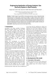
3.1.2.1 Impact energy<br />
Residence time depends on breaking velocity, i.e. the<br />
velocity at which the particle is fractured until it achieves<br />
a lower size than the screen opening size. In the case of<br />
hammer mill, the fragmentation (creation of new<br />
surfaces) is influenced by the energy released in impact.<br />
The impact energy is entirely in the form of the relative<br />
kinetic energy between the particle and the point of<br />
hammer where the impact happens.<br />
2<br />
r<br />
I = mν<br />
/ 2 = m ⋅ ( ν −ν<br />
) / 2 = m ⋅ ( r ⋅ω<br />
− v<br />
m<br />
p<br />
m<br />
p<br />
) / 2<br />
Where m is the particle mass, vr the relative lineal<br />
velocity between the particle velocity (vp), and velocity<br />
of the impact point in hammer (vm),r radius from mill<br />
axis to impact point in hammer and ωm the hammers<br />
angular velocity.<br />
Lower angular velocity ωm implies lower impact<br />
energy and lower particle fragmentation. Therefore, the<br />
original particle needs a higher number of impacts until<br />
the suitable size is achieved, increasing the residence<br />
time of particle in grinding chamber.<br />
3.1.2.2 Rotating air-particle flow inside the grinding<br />
chamber<br />
Higher angular velocity of internal elements produces<br />
higher rotating air-particle flow effect inside the chamber.<br />
As it is explained in section 3.1.1, this effect increases the<br />
angle between the particle trajectory and normal to the<br />
screen and decreases the probability of particle<br />
evacuation of the chamber.<br />
3.2 Drying effect during milling<br />
Grinding process causes significant secondary effects<br />
in final milled product. One of those is the mositure<br />
content reduction.<br />
Drying effect is caused by the heat released through<br />
two processes:<br />
Global drying: particles are in air-particles<br />
turbulent atmosphere receiving constantly heat<br />
flows from friction process between the mobile<br />
elements and between this elements and the airparticle<br />
flow.<br />
Local drying: It is caused by the evaporation of<br />
water content in particle due to released heat in<br />
impact. As the particle strikes and compresses,<br />
some of the kinetic energy is converted to strain<br />
energy in the compressed particle, with the sum<br />
of strain energy and kinetic energy equal to the<br />
impact energy. When the strain energy reaches<br />
that required to cause fracture, some of the<br />
stored strain energy is used to create new<br />
surfaces and the rest is converted to heat by<br />
relaxation of the fragments of breakage [14].<br />
The released heat as from friction process as from<br />
particle relaxation after impact is difficult to quantify. For<br />
this reason, a global energy balance in mill is raised. The<br />
objective is to determinate quantitevily the disiped and<br />
inverted energy in drying effect by means of the<br />
numerical value determination of implicit variables<br />
regarding as air as biomass:<br />
Input and output temperature<br />
Input and output air humidity and biomass<br />
moisture content<br />
Biomass feed rate and air mass flow<br />
3.2.1 Input and output temperature<br />
In practice, air-particle flow temperature inside the<br />
grinding chamber is increased during the milling.
Input and output temperature measurement of air and<br />
biomass allow to assess the heat flow spent in<br />
temperature increase.<br />
3.2.2 Input and output air humidity and biomass<br />
moisture content<br />
Moisture content is analyzed by means of initial and<br />
final biomass representative sampling [15]. Input and<br />
output air humidity are also instrumented.<br />
Water evaporation flow per mass unity is calculated<br />
considering the difference between input and output<br />
moisture content of biomass.<br />
On the other side, it is necessary to know the initial<br />
air humidity to assess the heat flow to increase the water<br />
vapour temperature.<br />
3.2.3 Biomass feed rate and air mass flow<br />
An average biomass feed rate is calculated as ratio<br />
between total raw biomass weigtht and the measured<br />
feeding time.<br />
Air volumetric flow is instrumented with an annubar<br />
flowmeter located in a pipe stretch in ausence of<br />
particles.<br />
4 MILLED <strong>BIOMASS</strong> SAMPLING<br />
Milling process characterization includes the analysis<br />
and influence of several variables and operational<br />
parameters in the final properties of milled biomass.<br />
First of all, different sampling methodologies to<br />
obtain a representative sample of the total comminuted<br />
biomass in milling experimental pilot plant are reviewed.<br />
4.1 Coning and quartering procedure.<br />
Once the total volume is milled, a representative<br />
sample can be obtained using the coning and quartering<br />
procedure. It is a progressive process, from the bulk<br />
volume (A) two quarters are taken (C and D) and they are<br />
divided into quarters again. The final sample is taken<br />
from the last one (G). The process is shown in figure 3.<br />
Figure 3: Coning and quartering procedure [16]<br />
It is a static sampling method where powder is<br />
confined or heaped. In this situation, size segregation<br />
occurs. Fine particles tend to remain at the center of the<br />
heap and coarse ones congregate at the periphery and the<br />
particle size analyse of the sample is disturbed.<br />
4.2 Gravity discharge sampling.<br />
Sampling from flowing powder such as discharging<br />
flow by gravity, the entire stream of powder should be<br />
sampled by traversing the stream, and the sampling<br />
should continue for a long series of short time intervals.<br />
The sampling point is located between cyclone outlet<br />
and screen classifier (e.g. Fig. 6, GS.1). Particles from<br />
grinders are conveyed until cyclone where are collected<br />
and precipitated to screen classifier. Two-way distributor<br />
(e.g. Fig. 4) has been introduced between both<br />
equipments to change the direction flow on discharge to<br />
the sampling outlet.<br />
This sampling method is simple, economic and<br />
allows taking a representative sample of collected<br />
biomass in cyclone. However, finer particles not<br />
collected by cyclone are not represented in this sample.<br />
Figure 4: Two-way distributor<br />
4.3 Isokinetic sampling<br />
The principal standard for direct measurement of<br />
local particle mass flux in most gas-solid flows is<br />
provided by the isokinetic sampling system. The<br />
isokinetic sampling principle requires that the sampling<br />
probe which is aligned with the flow (isoaxial) extracts<br />
airborne particulates at the sampling velocity matching<br />
the original undisturbed local flow velocity.<br />
In practice, the isokinetic sampling is closely<br />
approached but almost impossible to be rigorously<br />
realized. Several problems as the determination of flow<br />
velocity in the presence of significant amount of<br />
particles, the elimination of intrusive effect of the<br />
sampling probe, the interactions between particles and<br />
carrying fluid, the loss of particles to the wall deposition<br />
and particle bounce/reentrainment in the sampling tube<br />
are frequently observed. By these reasons, three types of<br />
sampling (e.g. Fig. 5) can be carried out: isokinetic<br />
(sampling velocity=stream velocity) or two kind of<br />
anisokinetic sampling: over-sucking (sampling<br />
velocity>stream velocity), under-sucking (sampling<br />
velocity< stream velocity).<br />
Figure 5: Isokinetic and non-isokinetic sampling [17]
Other important factors in this sampling method are<br />
the size and concentration of particles. A study of several<br />
isokinetic sampling points with radical different<br />
conditions is presented to overcome these problems<br />
4.3.1 Sampling points<br />
Milled biomass from Mills (IS.1)<br />
Sampling point is located between mill outlet and<br />
cyclone inlet, previous to intermediate screen classifier<br />
stage. Dilute phase air-solid flow is characterized by high<br />
solids concentration of full range of particle size (
4.4 Characterization of sampling point<br />
The extracted sample at IS.1 from mills is a<br />
representative of full range of milled biomass particles,<br />
however, this localization presents several problems to<br />
achieve the isokinetic conditions and the sampling can<br />
not be representative of this particle flow.<br />
The obtained samples in GS.1 and IS.2 are not<br />
representative of full range of milled particles. At GS.1<br />
point, it is sampling the collected particles by cyclone. At<br />
IS.2, the particles flow is from not collected in cyclone,<br />
in other words, the very fines particles of the full milled<br />
biomass particles. Both samples are not representative of<br />
full range, but the feasibility of a right sampling is higher<br />
due to, in the first place, GS.1 is a correct system to<br />
obtain a sample in discharge, and in the second place, at<br />
IS.2 presents less problems to achieve the isokinetic<br />
conditions.<br />
The possibility of three sampling point allows:<br />
To obtain a representative sample of the whole<br />
amount of milled biomass using two different<br />
methods.<br />
In the first place, to obtain a representative<br />
sampling of full range at IS.1<br />
In second place, to estimate a representative<br />
sampling of full range as composition of the<br />
obtained sample at GS.1 and IS.2:<br />
χt<br />
=<br />
m<br />
m<br />
m = m + m<br />
t<br />
GS1<br />
IS 2<br />
m<br />
· χ IS<br />
GS1<br />
IS 2<br />
χGS1<br />
+ ·<br />
GS1<br />
+ mIS<br />
2 mGS1<br />
+ mIS<br />
2<br />
where:<br />
χ: analyzed property (granulometry, moisture<br />
content, chemical composition or shape factor).<br />
Note: bulk density can not calculate as<br />
composition of both samples.<br />
m GS1: mass flux solids at GS.1<br />
mIS2: mass flux solids at IS.2<br />
Validation of extracted sample at IS.1 through<br />
the comparison his properties with the<br />
properties of the composed sample from GS.1<br />
and IS.2<br />
4.3.2 Milled biomass sample analysis<br />
Milled biomass characterization involves:<br />
Particle size distribution:<br />
It represents the mass percentage for each<br />
particle size interval. It is the most important<br />
parameter in analysis of milled product.<br />
Shape factor.<br />
The spherical approximation is a used<br />
<br />
commonly in powder handling. However, the<br />
milled biomass presents usually a cylindrical<br />
shape. Shape factor allows to asses the final<br />
particle shape.<br />
Moisture content<br />
This parameter is expressed as:<br />
Ww<br />
−Wd<br />
M = 100<br />
Ww<br />
where M is the moisture content expressed in<br />
percentage of wet matter, Ww is the weight of<br />
the wet sample and Wd the weight of the dry<br />
sample.<br />
The difference between inlet and outlet<br />
moisture content allows to asses the drying<br />
2<br />
effect during comminution. Several studies [8-<br />
10] have observed a decrease between 10 and<br />
30% of the initial moisture content as function<br />
different factors.<br />
Bulk density.<br />
Miling is ones of solids densification process<br />
due to bulk density increase with particle size<br />
decrease.<br />
Chemical composition<br />
It is observable that the particle size shows<br />
influence on chemical properties [21].<br />
5 CONCLUSIONS<br />
Several parameters have been instrumented to assess<br />
the influence on particle residence time on grinding<br />
chamber and on drying effect:<br />
Pressure, temperature, humidity and mass flow<br />
air at mill inlet and outlet.<br />
Moisture content, temperature and feed rate of<br />
biomass at mills inlet and outlet.<br />
Variable speed drives have been installed in<br />
mills to control the energy impact, in fans to<br />
control the mill outlet pressure and in belt<br />
conveyor to control the biomass feed rate.<br />
Milled biomass properties characterization has been<br />
realized to analyse the parameters influence on the final<br />
product properties.<br />
Three sampling methods have been studied to obtain<br />
a representative sample of milling process:<br />
Coning and quartering sampling can show size<br />
segregration due to the sample is taken out<br />
form stored milled biomass.<br />
Two-way distributor has been installed to<br />
obtain a representative sample in gravity<br />
discharge. Particle flow is in motion and size<br />
segregation is avoided.<br />
Two isokinetic sampling points have been<br />
analyzed where the air-particle flow conditions<br />
are extremely different. At first point, high<br />
solids concentration of all range of milled<br />
particle sizes in horizontal ducts, isokinetic<br />
sampling presents inertial effect of coarse<br />
particle, possible asymmetry in the solids<br />
concentration profiles as function sampling<br />
point height from the bottom of the pipe in the<br />
vertical plane of the cross section and finally,<br />
erroneous solid concentration measurement in<br />
case of anisokinetic sampling.<br />
At second point, low air-particles concentration<br />
of fines particles, isokinetic sampling can<br />
realize suitable, even the concentration<br />
measurement and representative sample can be<br />
obtained in anisokinetic conditions.<br />
Possibility to obtain two representative<br />
sampling of full range of milled biomass size:<br />
isokinetic sampling at first point and as<br />
composition of isokinetic sample at second<br />
point (fines particles representative) and gravity<br />
discharge sample (coarse particles<br />
representative).<br />
First isokinetic sample validation in<br />
comparison with a composition sample of<br />
gravity discharge sample and second isokinetic<br />
sample.
6 REFERENCES<br />
[1] S. Van Loo, J. Koppejan. The handbook of<br />
Biomass Combustion and Co-firing. Earthscan<br />
(2008).<br />
[2] L. Ortiz, A. Tejada, A. Vazquez.<br />
Aprovechamiento de la biomasa forestal<br />
producida por la cadena monte-industria. CIS-<br />
Madera, Universidad de Pontevedra<br />
[3] L.J. Naimi, S. Sokhansanj, S. Mani, M. Hoque, T.<br />
Bi, A.R.Womac, S, Narayan. Cost and<br />
Performance of Woody Biomass Size Reduction<br />
for Energy Production. CSBE/SCGAB Annual<br />
Conference Paper No: 06-107, Alberta, July 2006.<br />
[4] S.P. Venkata, A.R. Womac, N. Chevanan, S.<br />
Sokhansanj. Comminution Porperties of Biomass<br />
in Hammer Mill and its Particle Size<br />
Characterization. ASABE Annual Meeting,<br />
ASABE Paper No: 083785, Rhode Island, July<br />
2008.<br />
[5] L. Cadoche, G.D. López. Assessment of Size<br />
Reduction as a Preliminary Step in the Production<br />
of Ethanol from Lignocellulosic Waste.<br />
Biological Wastes (1989), vol. 30, pp. 153-157.<br />
[6] D.J. Schell, C. Harwood. Milling of<br />
Lignocellulosic Biomass. Applied Biochemistry<br />
and Biotechnology, vol. 45/46 (1994), pp. 159-<br />
168.<br />
[7] H. Spliethoff, K.R.G. Hein. Effect of Cocombustion<br />
of Biomass on Emissions in<br />
Pulverized Fuel Furnaces. Fuel Processing<br />
Technology, vol. 54 (1998), pp. 189-205.<br />
[8] M. Gil, A. Gonzalez, A. Gil. Evaluation of<br />
Milling Energy Requirements of Biomass<br />
Residues in a Semi-industrial Pilot Plant for Cofiring.<br />
Proceedings 16th European Biomass<br />
Conference and Exhibition, Valencia, 2008.<br />
[9] S. Mani, L.G. Tabil, S. Sokhansanj. Grinding<br />
Performance and Physical Properties of Wheat<br />
and Barley Straws, Corn Stover and Switchgrass.<br />
Biomass and Bioenergy, vol. 27 (2004), pp. 339-<br />
352.<br />
[10] L.S. Esteban, J.E. Carrasco. Evaluation of<br />
Different Strategies for Pulverization of Forest<br />
Biomasses- Powder Technology, vol. 166 (2006),<br />
pp. 139-151.<br />
[11] P.I. Miu, A.R. Womac, C. Igathinathane, S.<br />
Sokhansanj. Analysis of Biomass Comminution<br />
and Separation Process in Rotary Equipment. A<br />
Review. ASABE Annual International Meeting,<br />
ASABE Paper No: 066169, Oregon, July 2006.<br />
[12] A.R. Womac, C. Igathinathane, P. Biltra, P.Miu,<br />
T. Yang, S. Sokhansanj, S. Narayan. Biomass<br />
Pre-Processing Size Reduction with Instrumented<br />
Mills. ASABE Annual International Meeting,<br />
ASABE Paper No: 076046, Minnesota, June<br />
2007.<br />
[13] M. Hoque, S. Sokhansanj, L. Naimi, X. Lim, A.R.<br />
Womac. Review and analysis of performance and<br />
productivity of Size Reduction Equipment for<br />
Fibrous Materials. ASABE Annual International<br />
Meeting, ASABE Paper No: 076164, Minnesota,<br />
June 2007.<br />
[14] L.G. Austin. A Treatment of Impact Breakage of<br />
Particle. Powder Technology», vol. 126 (2002),<br />
pp. 85-90.<br />
[15] Standard Test Method for total moisture in Coal D<br />
3302-82. ASME, American Society for<br />
Mechanical Engineers.<br />
[16] T. Allen. Powder sampling and particle size<br />
measurement. Chapman & Hall (1997)<br />
[17] A. Diez-Lazaro, M. L. Hitchman, D. Littlejohn.<br />
Considerations for the selection and design os<br />
sampling systems for heterogeneous process in a<br />
stirred tank reactor. Chemical Engineering<br />
Research and Design, vol 83, pp 344-351.<br />
Glasgow, 2005.<br />
[18] D.R. Kaushal, Y. Tomita. Solids Concentration<br />
Profiles and Pressure Drop in Pipeline Flow of<br />
Multisized Particulated Slurries. International<br />
Journal of Multiphase Flow, vol 28, pp. 1697-<br />
1717. Japan, 2002.<br />
[19] S.L. Soo, C. Zhu. Instrumentation Flow Fluid-<br />
Particle Flow. University of Illinois ar Urbana-<br />
Champaign. Noyes Publications and William<br />
Andrew Publishing. USA.<br />
[20] Stationary source emissions. Measurement of<br />
velocity and volume flowrate of gas streams in<br />
ducts. International Standard ISO 10780<br />
[21] T.G.Bridgeman et al. Influence of Particle Size<br />
on the Analytical and Chemical Properties of Two<br />
Energy Crops. Fuel, vol. 86, pp. 60-72. 2007.