Staudacher 300-GS
Staudacher 300-GS Staudacher 300-GS
Construct_Staudacher 2/9/09 12:43 PM Page 144 CONSTRUCTION BY GEORGE LEU || PHOTOS BY PETE HALL & GERRY YARRISH Staudacher 300-GS A .60-SIZE SPORT-SCALE AEROBATIC CLASSIC The red-and-white Lap Map Staudacher is a well-known aerobatic airplane. Flown by Michael Goulian at the 1993 and ’94 IAC World Championships, it has always been one of my favorites. This model’s construction is the product of teamwork. Back in 2001, Model Airplane News editor Gerry Yarrish and I discussed several airplanes suitable for construction articles. We both thought that the Staudacher 300-GS was a natural for a comeback. I gave Gerry a 3-view drawing, and in about three weeks, he had turned them into a set of CAD plans for a .60-size model! I built the prototype and penciled in necessary changes on the plans. After a few flights, I noted other changes to tweak its flight performance. Gerry’s plans had a scale airfoil, but I thought a thicker one similar to Joe Bridi’s Kaos design would be better. Gerry adjusted the drawings and then built his “Beta” model. Gerry’s second model is featured in this article. Let’s start building. CONSTRUCTION You’ll need the fuselage to build the wing, so let’s start there. Cut out all of the parts shown on the template page. The fuselage is a basic straight-sided box that tapers from the firewall back to the tail post. The engine box slides into place through the firewall, and it ties the front formers together. To keep the fuselage straight, draw a guideline on your workbench, and then mark vertical centerlines on all the formers. Glue the top and bottom longerons to the fuselage sides; then place the formers over the guideline, and tack-glue the sides to the formers. Check the alignment, and then permanently glue formers F1, F2 and F3 into place. Lift the fuselage from the workbench, glue the wing-saddle doublers into place, pull the tail ends together and glue them together. Recheck the fuselage for straightness, and glue the crosspieces into place. 144 MODELAIRPLANENEWS.COM George Leu with the second model built from the plans. The decals and the pilot figure come from Cajun RC. I built my model with 1 ⁄8-inch balsa sides with 1 ⁄4-inch square longerons, verticals and diagonal braces. Gerry made his fuselage with 1 ⁄8-inch lite-ply sides and without verticals or diagonal braces. He also cut openings in the sides to save weight. Install the upper formers, F1-T through F6-T, glue the top longerons into place and sheet the top of the fuselage with 3 ⁄32-inch balsa. Wet the sheeting’s outer side to help it bend into shape. Glue the 1 ⁄16-inch crossgrain balsa cockpit floor into place, and make the cockpit sides with 1 ⁄4-inch balsa strips. Sand the balsa to blend the cockpit section into the aft turtle deck. Fit the main 1 ⁄4-inch ply landing-gear plate into place. It interlocks with tabs and notches in the bottom of the firewall, the fuselage sides and former F2. Don’t glue it into place until after you’ve installed the wing. Also, don’t glue
- Page 2 and 3: Construct_Staudacher 2/9/09 12:43 P
- Page 4: Construct_Staudacher 2/9/09 12:44 P
Construct_<strong>Staudacher</strong> 2/9/09 12:43 PM Page 144<br />
CONSTRUCTION<br />
BY GEORGE LEU || PHOTOS BY PETE HALL & GERRY YARRISH<br />
<strong>Staudacher</strong> <strong>300</strong>-<strong>GS</strong><br />
A .60-SIZE SPORT-SCALE AEROBATIC CLASSIC<br />
The red-and-white Lap Map<br />
<strong>Staudacher</strong> is a well-known<br />
aerobatic airplane. Flown by<br />
Michael Goulian at the 1993<br />
and ’94 IAC World Championships,<br />
it has always been one of my<br />
favorites.<br />
This model’s construction is the product<br />
of teamwork. Back in 2001, Model Airplane<br />
News editor Gerry Yarrish and I discussed<br />
several airplanes suitable for construction<br />
articles. We both thought that the <strong>Staudacher</strong><br />
<strong>300</strong>-<strong>GS</strong> was a natural for a comeback.<br />
I gave Gerry a 3-view drawing, and in about<br />
three weeks, he had turned them into a set<br />
of CAD plans for a .60-size model!<br />
I built the prototype and penciled in necessary<br />
changes on the plans. After a few<br />
flights, I noted other changes to tweak its<br />
flight performance. Gerry’s plans had a<br />
scale airfoil, but I thought a thicker one similar<br />
to Joe Bridi’s Kaos design would be<br />
better. Gerry adjusted the drawings and<br />
then built his “Beta” model. Gerry’s second<br />
model is featured in this article. Let’s start<br />
building.<br />
CONSTRUCTION<br />
You’ll need the fuselage to build the wing,<br />
so let’s start there. Cut out all of the parts<br />
shown on the template page. The fuselage<br />
is a basic straight-sided box that tapers from<br />
the firewall back to the tail post. The engine<br />
box slides into place through the firewall,<br />
and it ties the front formers together. To<br />
keep the fuselage straight, draw a guideline<br />
on your workbench, and then mark vertical<br />
centerlines on all the formers. Glue the top<br />
and bottom longerons to the fuselage sides;<br />
then place the formers over the guideline,<br />
and tack-glue the sides to the formers.<br />
Check the alignment, and then permanently<br />
glue formers F1, F2 and F3 into<br />
place. Lift the fuselage from the workbench,<br />
glue the wing-saddle doublers into place,<br />
pull the tail ends together and glue them<br />
together. Recheck the fuselage for straightness,<br />
and glue the crosspieces into place.<br />
144 MODELAIRPLANENEWS.COM<br />
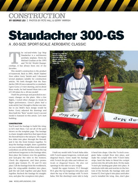
George Leu with the<br />
second model built<br />
from the plans. The<br />
decals and the pilot<br />
figure come from<br />
Cajun RC.<br />
I built my model with 1 ⁄8-inch balsa sides<br />
with 1 ⁄4-inch square longerons, verticals and<br />
diagonal braces. Gerry made his fuselage<br />
with 1 ⁄8-inch lite-ply sides and without verticals<br />
or diagonal braces. He also cut<br />
openings in the sides to save weight.<br />
Install the upper formers, F1-T through<br />
F6-T, glue the top longerons into place and<br />
sheet the top of the fuselage with 3 ⁄32-inch<br />
balsa. Wet the sheeting’s outer side to help<br />
it bend into shape. Glue the 1 ⁄16-inch crossgrain<br />
balsa cockpit floor into place, and<br />
make the cockpit sides with 1 ⁄4-inch balsa<br />
strips. Sand the balsa to blend the cockpit<br />
section into the aft turtle deck. Fit the main<br />
1 ⁄4-inch ply landing-gear plate into place. It<br />
interlocks with tabs and notches in the bottom<br />
of the firewall, the fuselage sides and<br />
former F2. Don’t glue it into place until after<br />
you’ve installed the wing. Also, don’t glue
Construct_<strong>Staudacher</strong> 2/9/09 12:43 PM Page 145<br />
SPECIFICATIONS<br />
MODEL: <strong>Staudacher</strong> <strong>300</strong>-<strong>GS</strong><br />
TYPE: sport scale aerobatic<br />
WIN<strong>GS</strong>PAN: 64.25 in.<br />
WING AREA: 695.7 sq. in.<br />
WEIGHT: 8 lb. 9 oz. (137 oz.)<br />
WING LOADING: 28.36 oz./sq. ft.<br />
LENGTH: 55 in.<br />
ENGINE REQ’D: .60 to .90 2-stroke,<br />
.91 to 1.00 4-stroke<br />
RADIO REQ’D: 4-channel (throttle,<br />
rudder, elevator, aileron)<br />
GEAR USED:<br />
ENGINE: O.S. .61FX<br />
PROP: Master Airscrew 12x7<br />
FUEL: Byron Originals 15% nitro,<br />
18% oil<br />
RADIO: JR 9303 transmitter, JR<br />
DS811 digital servos, R649 JR<br />
receiver<br />
the bottom 1 ⁄16-inch cross-grain fuselage<br />
sheeting into place until after you’ve<br />
installed all of the radio gear.<br />
The engine-box length is determined by<br />
the engine and mount you use. I used a 4stroke<br />
Saito .91 engine, and Gerry used an<br />
O.S. .61FX 2-stroke. Install the blind nuts,<br />
and glue the firewall into place with 30minute<br />
epoxy. I used Bob Smith Industries<br />
CA and 30-minute epoxy throughout.<br />
TAIL FEATHERS<br />
The tail surfaces are made out of 1 ⁄4-inch-thick<br />
balsa stock as shown on the plans. Be sure to<br />
install the balsa hinge blocks before covering.<br />
A 1 ⁄4-inch dowel joins the elevator halves.<br />
Tack-glue the horizontal stab and vertical<br />
The <strong>Staudacher</strong>’s parts are easy to cut out. You can also buy laser-cut parts<br />
from Patrick Fallacaro at LasercutUSA.com.<br />
TO ORDER THE FULL-SIZE PLAN, VISIT RCSTORE.COM.<br />
THE CANOPY IS FROM A GOLDBERG<br />
STAUDACHER KIT, AND THE MAIN LANDING<br />
GEAR IS FROM A LANIER EDGE 540T ARF<br />
fin into place; then shape the fairing block<br />
out of several layers of 1 ⁄4-inch balsa sheet.<br />
Tack-glue the blocks to the aft former,<br />
remove the fin and stabilizer, install temporary<br />
1 ⁄4-inch-thick spacers in the slots,<br />
and then finish carving and sanding the<br />
blocks to blend into the fuselage. Don’t glue<br />
the tail surfaces into place until after all of<br />
the parts have been covered.<br />
WING<br />
I used an old “Adjust-O-Jig” rig to build the<br />
wing panels, but you can easily build the<br />
wing upside-down over the plans. Use balsa<br />
shims under the ribs to keep the trailing<br />
edges straight. Pin the main spar on top of<br />
the plans, and then attach the ribs to the<br />
spar. Install the bottom spar, and check the<br />
rib alignment. Tack-glue the ribs to the<br />
spars, and then add the 1 ⁄8-inch sub-leading<br />
edge sheet, and glue it to each of the ribs.<br />
Slide the aft spar into place, and then tackglue<br />
the trailing-edge sheeting to the ribs.<br />
Be sure everything remains straight and<br />
true. Bevel the aft edge of the sheeting, add<br />
the second aft spar, and glue the bottom<br />
trailing-edge sheeting into place. I installed<br />
a solid balsa trailing edge between the top<br />
and bottom sheeting, but Gerry built his<br />
wing without it. Both ways work.<br />
The tail surfaces are made of 1 ⁄4-inch-thick balsa and are built directly over the<br />
plans.<br />
JANUARY 2007 145
Construct_<strong>Staudacher</strong> 2/9/09 12:43 PM Page 146<br />
CONSTRUCTION<br />
The sides of the engine box tie the firewall and formers F1 and F2 together.<br />
You can adjust the length of the box to suit the engine you choose.<br />
The servos are installed on plywood rails. Note the throttle cable and fuel-tank<br />
installation. I used hardwood dowels for the rudder and elevator pushrods.<br />
Tack-glue rib 2A into its approximate<br />
position, and leave the sub-leading-edge<br />
strip extra-long. To determine the exact<br />
placement of this half rib, you will have to<br />
attach the wing assembly to the fuselage.<br />
Repeat these steps for the second panel,<br />
and join them with the 1 ⁄8-inch dihedral<br />
braces epoxied to the front and back of the<br />
main spars. The tops of the wing panels<br />
should be flat against the building surface<br />
while the epoxy cures. Slide some balsa fill<br />
into the space between the wing ribs where<br />
the wing hold-down bolts will be installed.<br />
Center the wing in the wing saddle, and<br />
measure from each wingtip to the tail post;<br />
the sides should be the same. Trim the subleading<br />
edge sheets so that they just touch<br />
the fuselage sides; then break the half ribs<br />
free, and slide them against the fuselage<br />
sides. Slip a thin card-stock spacer between<br />
146 MODELAIRPLANENEWS.COM<br />
the ribs and the fuselage sides. Glue the ribs<br />
to the spars and the sub-leading edges.<br />
Install the center 1 ⁄8-inch plywood plate and<br />
sub-spars for the wing-alignment dowels.<br />
Before you glue the landing-gear mounting<br />
plate into place, drill through the holes in<br />
former F2 and into the plate. Remove the<br />
wing from the fuselage, and drill the holes<br />
in the plate and into the ply dihedral braces.<br />
Slide the wing-attachment dowels into<br />
place, and check their fit by placing the<br />
wing back in the saddle. The dowels should<br />
fit snugly in the holes in the former. If everything<br />
fits properly, remove the dowels, coat<br />
them with epoxy and re-insert them into<br />
the wing so that about 1 ⁄2 inch protrudes<br />
from the wing plate. Glue the leading-edge<br />
and center-section sheeting to the wing.<br />
Install the aileron servos, and cut away<br />
the aileron portions of the wing. Cap the<br />
The engine cowl is made out of balsa and foam blocks. Here, the engine determines<br />
the position of the spinner relative to the front of the cowl. See the complete<br />
“How-To” article in the July 2006 issue.<br />
I used Robart control horns and HingePoints for the elevator and rudder. The<br />
Du-Bro tailwheel is being installed. A metal strap and screw will attach it to<br />
the bottom of the rudder.<br />
aileron bays with 1 ⁄4-inch balsa, and add the<br />
leading edges and side caps to the ailerons.<br />
Bevel the leading edges, and install the<br />
aileron hinges. Install the hinge blocks<br />
inside the wing panels. Cut rib holes for the<br />
aileron-servo leads and glue the rib capstripping<br />
into place. Glue the 3 ⁄8-inch balsa<br />
leading edges to the front of the wing panels;<br />
then carve and sand them to shape.<br />
Install the hold-down blocks in the fuselage,<br />
reinstall the wing and drill through<br />
the wing for the hold-down bolts. Tap the<br />
holes in the blocks for 1 ⁄4-20 nylon bolts,<br />
and bolt the wing into place. Now build the<br />
lower wing/fuselage fairings, and glue them<br />
to the bottom of the wing.<br />
FINAL ASSEMBLY<br />
I used Robart HingePoints and did all the<br />
drilling and fitting before I covered the
Construct_<strong>Staudacher</strong> 2/9/09 12:44 PM Page 148<br />
CONSTRUCTION<br />
The aileron-servo installation and the aileron<br />
control linkage. Holes cut in the ribs allow the<br />
servo leads to pass through to the center of the<br />
wing.<br />
model in UltraCote film. The Lap Map<br />
decals are available from Cajun RC.<br />
The engine cowl is made out of balsa and<br />
foam blocks covered with fiberglass cloth<br />
and epoxy finishing resin. Cross-sections<br />
are shown on the plans. (See Gerry’s detailed<br />
how-to article in the July 2006 issue.)<br />
I used a Carl Goldberg .60-size <strong>Staudacher</strong><br />
canopy, but others are also available;<br />
Lap Map pilot — then and now!<br />
In 1992, Michael Goulian was a top-ranked U.S. aerobatics pilot and a silver medalist<br />
in the World Unlimited class. A year later, he won the Fond du Lac Cup, and in 1994,<br />
he earned a spot on the U.S. national aerobatic team flying his well-known red-andwhite<br />
“Lap Map” <strong>Staudacher</strong> <strong>300</strong>-<strong>GS</strong>. In 1995, Michael was the U.S. National<br />
Champion and went on to compete on the 1996 and 1998 teams.<br />
Michael has gone on to become one of the country’s leading high-energy aerobatics<br />
show pilots, and he regularly shares the flightline and aerobatics box with other<br />
well-known pilots such as Patty Wagstaff, Matt Chapman, Jeff Mawhinney, Sergei<br />
Boriak and Sean Tucker, to name just a few.<br />
Today, Michael flies an Extra <strong>300</strong> SHP, an upgraded version of the <strong>300</strong> S, which he<br />
debuted at the Red Bull Air race in Berlin, Germany. The series is held in cities worldwide,<br />
including Abu Dhabi (United Arab Emirates), Barcelona (Spain), Istanbul<br />
(Turkey), Perth (Australia) and San Francisco, CA. As this article goes to press, he is<br />
in fifth place overall!<br />
148 MODELAIRPLANENEWS.COM<br />
The center section of the wing is notched to fit in<br />
the wing saddle. Drill through the holes in former<br />
F2 and into this plywood plate to install the wing<br />
attachment dowels.<br />
just cut them to fit. A Cajun RC 1 ⁄5-scale<br />
pilot and a homemade instrument panel<br />
finish off the cockpit. The landing gear<br />
comes from a Lanier RC Edge 540T kit, and<br />
the wheel pants are from Stan’s FiberTech.<br />
The Du-Bro tailwheel assembly and a<br />
Tru-Turn spinner complete the hardware<br />
package. Check the model’s CG; it should<br />
be 4 1 ⁄2 inches aft of the wing’s leading edge<br />
The bottom of the wing blends into the fuselage<br />
with these built-up balsa center-section fairings.<br />
Note that the landing gear is installed in halves.<br />
measured next to the fuselage.<br />
I used hardwood dowels and threaded<br />
2-56 pushrod wires to complete the elevator<br />
and rudder control links and a Sullivan<br />
Products metal throttle cable and Du-Bro<br />
EZ Connectors for engine control.<br />
Install the receiver and battery in front of<br />
the servos, and pack foam around them.<br />
Install the fuel tanks and fuel lines, and<br />
connect them to the engine.<br />
FLYING THE “STAUD”<br />
For your first flight,take it slow and easy;<br />
set the control throws as follows:<br />
• Ailerons: ± 3 ⁄4 in. (low); ±1 in. (high)<br />
• Elevator: ± 1 ⁄2 in. (low); ± 3 ⁄4 in. (high)<br />
• Rudder: ±1 in. left and right (low); 2 in. left<br />
and right (high)<br />
• Expo: 20 to 30%<br />
Though not intended for beginners, the<br />
<strong>Staudacher</strong> is a smooth and neutrally stable<br />
flyer. Takeoffs are easy with hardly any need<br />
for rudder. It is an honest airplane and it does<br />
everything in the aerobatics book. There is<br />
very little pitch-trim change throughout the<br />
throttle range, and inverted flight requires<br />
only a touch of down-elevator. There is,<br />
however, a slight pitch coupling (toward the<br />
gear) during knife-edge flight, but this is<br />
easily dialed out with radio mixing. The<br />
wing’s thick airfoil prevents speed from<br />
building up too much, and you can easily<br />
land the model in a 3-point attitude.<br />
Whether you like fun-scale, sport aerobatics<br />
or just hot Sunday flying, the<br />
<strong>Staudacher</strong> <strong>300</strong>-<strong>GS</strong> is always a winner.<br />
Enjoy!<br />
See the Source Guide on page 166 for manufacturers’ contact information.<br />
MODELAIRPLANENEWS.COM<br />
FOR MODEL FLIGHT SHOTS,<br />
FULL-SIZE AIRCRAFT PHOTOS<br />
AND A 3-VIEW DRAWING


