Engineering Application of Exergy Analysis - circe - Universidad de ...
Engineering Application of Exergy Analysis - circe - Universidad de ...
Engineering Application of Exergy Analysis - circe - Universidad de ...

You also want an ePaper? Increase the reach of your titles
YUMPU automatically turns print PDFs into web optimized ePapers that Google loves.
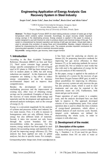
<strong>Engineering</strong> <strong>Application</strong> <strong>of</strong> <strong>Exergy</strong> <strong>Analysis</strong>: Gas<br />
Recovery System in Steel Industry<br />
Sergio Usón a , Javier Uche a , Juan José Arribas b , Rocío Llera c and Alicia Valero a<br />
a CIRCE Institute <strong>Universidad</strong> <strong>de</strong> Zaragoza, Zaragoza, Spain<br />
b Arcelor-Mittal España, Avilés, Spain<br />
c Project <strong>Engineering</strong> Area <strong>of</strong> University <strong>of</strong> Oviedo, Oviedo, Spain<br />
Abstract: The Basic Oxygen Furnace (BOF) for steel making produces a stream <strong>of</strong> waste gas at high<br />
temperature which contains carbon monoxi<strong>de</strong>. Accordingly, its proper recovery entails important<br />
energy savings in the steelmaking process. <strong>Exergy</strong> analysis is applied in this paper to analyze a<br />
system <strong>de</strong>signed to use both thermal (in or<strong>de</strong>r to produce steam) and chemical energy <strong>of</strong> this gas. The<br />
system is characterized by transient operation and storing <strong>of</strong> both gas and steam. Actual plant data is<br />
used to calculate time evolution <strong>of</strong> exergy flows and irreversibilities. Besi<strong>de</strong>s, integral indicators are<br />
<strong>de</strong>fined for characterizing the whole recovery cycle. The analysis provi<strong>de</strong>s important conclusions for<br />
improving plant operation, in or<strong>de</strong>r to maximize recovered exergy.<br />
Keywords: exergy analysis, gas recovery, basic oxygen furnace<br />
1. Introduction<br />
According to the Best Available Techniques<br />
Reference Document (BREF) on Iron and Steel<br />
[1], ‘Steel sector consume huge amounts <strong>of</strong><br />
energy: specific consumption <strong>of</strong> 23 GJ/t <strong>of</strong> liquid<br />
steel in EU plants in 1980 has been reduced to 18<br />
GJ/t in mo<strong>de</strong>rn plants in 2004, but still strong<br />
reductions are required’. In this framework, steel<br />
companies are making a big effort to reduce<br />
energy consumption in or<strong>de</strong>r to <strong>de</strong>crease<br />
environmental impact and to improve their<br />
competitiveness.<br />
Besi<strong>de</strong>s the <strong>de</strong>velopment <strong>of</strong> innovative<br />
steelmaking processes and the improvement <strong>of</strong><br />
existing ones, other ways <strong>of</strong> obtaining energy<br />
savings can be consi<strong>de</strong>red. Examples <strong>of</strong> them are<br />
the recovery <strong>of</strong> waste streams (both energy and<br />
materials) and the <strong>de</strong>velopment and application <strong>of</strong><br />
advanced analysis techniques, such as the concept<br />
<strong>of</strong> exergy [2, 3].<br />
<strong>Exergy</strong> is a convenient magnitu<strong>de</strong> for the analysis<br />
<strong>of</strong> systems and processes within steel industry for<br />
two main reasons. First, it is able to measure in<br />
homogeneous units not only different forms <strong>of</strong><br />
energy but also different kinds <strong>of</strong> materials.<br />
Second, it takes into account not only losses<br />
through the system boundary but also<br />
irreversibilities within the processes. For this<br />
reasons, exergy analysis has been applied in steel<br />
industry for accounting energy and materials flows<br />
[4] and for improving energy efficiency [5]. This<br />
analysis has been applied not only to global<br />
analyses, but also to specific issues. For example,<br />
Corresponding Author: Sergio Usón, Email: suson@unizar.es<br />
it has been used for analyzing an electric arc<br />
furnace [6], for proposing innovative methods for<br />
improving hot gas stoves efficiency in blast<br />
furnaces [7], or for analyzing methods for recover<br />
gas streams [8]. Not so related to steel works but<br />
also with steel is the application <strong>of</strong> exergy for the<br />
life cycle analysis <strong>of</strong> this material [9].<br />
In this paper, exergy is applied to the analysis <strong>of</strong><br />
the operation <strong>of</strong> a system for the recovery <strong>of</strong> gas<br />
from Basic Oxygen Furnace (BOF gas), in or<strong>de</strong>r to<br />
<strong>de</strong>tect possibilities for improving its efficiency.<br />
The gas recovery system not only recovers the gas<br />
but also produces steam, which is used in steel<br />
treatments and can also be exported to the<br />
steelworks steam net [10]. Furthermore, both<br />
steam and gas can be stored.<br />
Proper operation <strong>of</strong> such system is a complex<br />
issue, and the analysis <strong>de</strong>veloped here can shed<br />
light to improve it. The approach <strong>de</strong>veloped<br />
consists <strong>of</strong> two complimentary parts. First, actual<br />
operation data is used to obtain the time evolution<br />
<strong>of</strong> exergy-based parameters, which allows a<br />
<strong>de</strong>tailed analysis <strong>of</strong> each recovery cycle. Second,<br />
integral cycle indicators are <strong>de</strong>fined for<br />
characterizing the whole cycle, in or<strong>de</strong>r to<br />
compare it with other ones.<br />
2. Development <strong>of</strong> the mo<strong>de</strong>l.<br />
2.1. Description <strong>of</strong> the system<br />
A scheme <strong>of</strong> the gas recovery system is <strong>de</strong>picted in<br />
Fig. 1. Numbers 1 to 10 are used for gas flows,<br />
while numbers from 101 on refer to water or<br />
steam.<br />
http://www.ecos2010.ch 1 14-17th june 2010, Lausanne, Switzerland
2<br />
EXTERNAL AIR<br />
103<br />
M<br />
101<br />
DRUM<br />
HRSG<br />
3<br />
1<br />
M<br />
104<br />
P<br />
102<br />
COND.<br />
1<br />
COND.<br />
2<br />
ACC.<br />
1<br />
Gas leaving the converter (flow 1) reacts with<br />
external air entering through the hole between the<br />
converter and the heat recovery generator (flow 2)<br />
to form flow 3, which is cooled in the heat<br />
recovery steam generator (HRSG) down to point<br />
4. It should be noted that part <strong>of</strong> the burning<br />
reactions take place insi<strong>de</strong> the HRSG, but here<br />
reaction and heat transfer have been separated for<br />
simplicity. Besi<strong>de</strong>s, the operator has two ways <strong>of</strong><br />
controlling the amount <strong>of</strong> external air (un<strong>de</strong>r<br />
certain limits). First, the hood that directs gases<br />
towards the heat recovery steam generator can be<br />
moved upwards and downwards (and thus the gap<br />
between the converter and the hood can be<br />
modified). Second, position <strong>of</strong> venturi located<br />
downstream can also be modified.<br />
Gas leaving the HRSG (flow 4) is washed and<br />
cooled in two washing venturi. Afterwards, a third<br />
venturi is present to measure the gas flow, and a<br />
blower establishes the draft nee<strong>de</strong>d to impulse the<br />
gases. Finally, a three-way valve is located in<br />
ACC.<br />
2<br />
4 5 6 7 8 10<br />
WASHING WASHING VENTURI<br />
BLOWER GASHOLDER<br />
VENTURI 1 VENTURI 2<br />
GAS<br />
T X<br />
T T<br />
M<br />
T<br />
GAS FROM<br />
CONVERTER<br />
TO STEEL<br />
TREATMENT<br />
131<br />
105<br />
106<br />
109 110<br />
M M<br />
111 112<br />
107<br />
108 114<br />
113<br />
121<br />
131<br />
117<br />
122<br />
M<br />
VENT<br />
132<br />
133 134<br />
115 116<br />
118 119<br />
123 124<br />
ACC.<br />
3<br />
120<br />
125<br />
126<br />
129<br />
ACC.<br />
4<br />
128<br />
130<br />
FLARE<br />
Fig. 1. Flow scheme <strong>of</strong> the gas recovery system.<br />
127<br />
9<br />
136<br />
DEAERATOR<br />
138<br />
STEAM TO NET<br />
135<br />
137<br />
or<strong>de</strong>r to choose whether the gas is flared (flow 9)<br />
or stored in the gashol<strong>de</strong>r (flow 10). In this choice,<br />
quality requirements to store gas are consi<strong>de</strong>red.<br />
Heat released during gas cooling within the HRSG<br />
is used to transform saturated water from the drum<br />
(flow 101) into a mixture <strong>of</strong> liquid and steam<br />
going back to that component (flow 102). Part <strong>of</strong><br />
the steam produced in the drum (flow 103) is used<br />
for steel treatments (flow 104). Another part flows<br />
through a pressure regulator and then can flow<br />
towards the general steam network <strong>of</strong> the<br />
steelworks (flow 135) or be used by the <strong>de</strong>aerator<br />
(flow 136). It should be noted that it is possible to<br />
import medium pressure from the steam network;<br />
accordingly, flow 135 can have two senses.<br />
Steam generated in the drum can also be stored in<br />
four accumulators for later use (flows 114 to 120).<br />
Besi<strong>de</strong>s, if there is excess <strong>of</strong> steam, it is possible to<br />
con<strong>de</strong>nse part <strong>of</strong> it in two con<strong>de</strong>nsers (flows 109<br />
and 110). For safety reasons, if pressure increases,<br />
http://www.ecos2010.ch 2 14-17th june 2010, Lausanne, Switzerland<br />
P<br />
M<br />
P<br />
M<br />
M
part <strong>of</strong> the steam can be vented (flow 132,<br />
normally closed).<br />
Liquid water from con<strong>de</strong>nsers and accumulators<br />
(flows 111-113, 121-127) can be pumped and<br />
returned to the drum. Besi<strong>de</strong>s, the drum can be fed<br />
from external fresh water (flow 137), once the<br />
<strong>de</strong>aerator has passed.<br />
2.2. Thermodynamic mo<strong>de</strong>l.<br />
Figure 1shows plant instrumentation used for the<br />
characterization <strong>of</strong> the thermodynamic state <strong>of</strong> the<br />
system: flow rates (M), pressures (P), temperatures<br />
(T) and gas composition (X). The latter refers to<br />
concentration <strong>of</strong> CO, CO2 and O2 in dry basis.<br />
Although they have not been represented in the<br />
figure, levels <strong>of</strong> the four accumulators and position<br />
<strong>of</strong> three-way valve are also available.<br />
2.2.1. Gas flows<br />
To characterize flows 3 to 10, measurements <strong>of</strong><br />
flow rate and dry gas composition are available. In<br />
or<strong>de</strong>r to calculate the amount <strong>of</strong> water, it has been<br />
consi<strong>de</strong>red that gas is dry in flows 3 and 4 and that<br />
is water saturated in flows 5 and 6. In the other<br />
flows, temperature increases slightly and no water<br />
is ad<strong>de</strong>d. Accordingly, it has been consi<strong>de</strong>red that<br />
the flow <strong>of</strong> water is kept constant. Nitrogen<br />
concentration is calculated by difference and, since<br />
it is no reaction, flow <strong>of</strong> CO, CO2, O2 and N2 is<br />
maintained in flows 3 to 8. Depending on the<br />
position <strong>of</strong> the three way valve, flow 8 continues<br />
either in flow 9 or in flow 10.<br />
In or<strong>de</strong>r to calculate flows 1 (converter output) and<br />
2 (external air), a balance to carbon, nitrogen and<br />
oxygen is ma<strong>de</strong>. Besi<strong>de</strong>s, composition <strong>of</strong> 1 is<br />
known (air) and it has been consi<strong>de</strong>red that gas<br />
flow 2 does not contain significant amounts <strong>of</strong><br />
CO2 or O2.<br />
There are temperature measurements in flows 4 to<br />
8 (except in point 7, which has been supposed to<br />
be equal to 6). Temperature <strong>of</strong> flow 2 is equal to<br />
the environment (consi<strong>de</strong>ring that the control<br />
volume is far enough from the hot area around the<br />
converter), and temperature <strong>of</strong> flow 1 is calculated<br />
by energy balance <strong>of</strong> the HRSG.<br />
2.2.2. Water/steam flows<br />
First, there is no measurement <strong>of</strong> the flow <strong>of</strong><br />
saturated liquid leaving the drum towards the<br />
HRSG (flow 101); accordingly, it is fixed by the<br />
<strong>de</strong>sign values. Since flows 131 and 103 are<br />
known, mass accumulated in the drum is<br />
calculated. Due to available measurements in<br />
flows 104 and 135 (and assuming that no steam is<br />
vented), it is possible to calculate flows 105, 106,<br />
107, 133 and 134. Besi<strong>de</strong>s, flows entering the<br />
con<strong>de</strong>nsers are also measured.<br />
In or<strong>de</strong>r to calculate flows corresponding to the<br />
accumulators, rate <strong>of</strong> level variation is used. This<br />
rate can be obtained because evolution <strong>of</strong> all<br />
signals is available. Besi<strong>de</strong>s, it has been supposed<br />
that the amount <strong>of</strong> water leaving all accumulators<br />
is the same. Finally, measurement in 137 allows<br />
one to calculate mass accumulation in the<br />
<strong>de</strong>aerator.<br />
To calculate intensive properties, three pressure<br />
zones have been consi<strong>de</strong>red:<br />
▪ Drum (high pressure): flows 103 to 133<br />
▪ Steam network (medium pressure): flows 134<br />
to 136<br />
▪ Deaerator: flows 137 and 138<br />
Besi<strong>de</strong>s, isentropic efficiency is imposed for<br />
pumps. Finally, an equation is introduced relating<br />
matter and energy accumulation in the drum in<br />
or<strong>de</strong>r to calculate the quality <strong>of</strong> flow 102 (which,<br />
in turn, allows one to calculate the temperature <strong>of</strong><br />
gases leaving the converter by the energy balance<br />
<strong>of</strong> the HRSG).<br />
2.3. <strong>Exergy</strong> analysis.<br />
Once all flows <strong>de</strong>fined in Fig. 1 have been<br />
characterized as <strong>de</strong>scribed in the previous sections,<br />
exergy analysis can be performed [2,3]. <strong>Exergy</strong> <strong>of</strong><br />
a flow i is composed <strong>of</strong> two parts: physical and<br />
chemical:<br />
B = B + B<br />
, (1)<br />
i ph, i ch, i<br />
Physical exergy appears because the flow has<br />
different conditions <strong>of</strong> temperature and/or pressure<br />
that the reference environment:<br />
( ) ( )<br />
B ph, i = fmi⋅⎡hih0, i T0 sis ⎤<br />
⎣<br />
− − ⋅ − 0, i ⎦<br />
, (2)<br />
where fm is the molar rate, h is specific enthalpy<br />
and s is specific entropy. Properties are evaluated<br />
at the conditions <strong>of</strong> flow i and at reference<br />
conditions 0 (but for the same composition <strong>of</strong> flow<br />
i).<br />
Chemical exergy is due to the composition <strong>of</strong> the<br />
flow (different than that <strong>of</strong> the environment):<br />
n<br />
∑<br />
( ln )<br />
B = fm ⋅ x b −R⋅T ⋅ x , (3)<br />
ch, i i i, j ch, j 0 i, j<br />
j=<br />
1<br />
http://www.ecos2010.ch 3 14-17th june 2010, Lausanne, Switzerland
where xi,j is the molar fraction <strong>of</strong> component j in<br />
flow i, bch,j is the specific exergy <strong>of</strong> component j<br />
and R is the constant <strong>of</strong> gases. The second part <strong>of</strong><br />
the equation refers to the difference between the<br />
exergy <strong>of</strong> the different components <strong>of</strong> a mixture<br />
isolated, and the exergy <strong>of</strong> the components all<br />
mixed together. Szargut reference state [2] has<br />
been used for the calculation <strong>of</strong> chemical exergy.<br />
After calculating the exergy <strong>of</strong> all flows, it is<br />
possible to obtain the irreversibility <strong>of</strong> each<br />
component (Ik). It should be noted that, in this<br />
paper, irreversibility will also inclu<strong>de</strong> losses<br />
(external irreversibilities).<br />
I = B − B<br />
, (4)<br />
∑ ∑<br />
k i i<br />
inputs outputs<br />
In or<strong>de</strong>r to put in perspective the values <strong>of</strong> exergy<br />
and irreversibility obtained, two non-dimensional<br />
parameters have been <strong>de</strong>fined. First, several<br />
efficiencies calculated by dividing the exergy <strong>of</strong><br />
the outputs <strong>of</strong> the system into the main input<br />
(exergy <strong>of</strong> gases leaving the converter):<br />
Bi<br />
η i =<br />
B<br />
<br />
, (5)<br />
<br />
1<br />
Besi<strong>de</strong>s, irreversibility <strong>of</strong> components is ma<strong>de</strong><br />
non-dimensional by dividing it also into the exergy<br />
<strong>of</strong> flow 1:<br />
I<br />
k ϕ k = , (6)<br />
B<br />
1<br />
2.4. Parameters for characterizing the<br />
whole cycle.<br />
<strong>Exergy</strong> flows, irreversibility and non-dimensional<br />
parameters <strong>de</strong>fined in the previous section vary<br />
with time, and thus they are suitable for a <strong>de</strong>tailed<br />
study <strong>of</strong> a given recovery cycle. However, in or<strong>de</strong>r<br />
to summarize the results <strong>of</strong> a cycle and to compare<br />
it with others, integral indicators characterizing the<br />
whole cycle are nee<strong>de</strong>d.<br />
Accordingly, the exergy <strong>of</strong> a flow i over a cycle<br />
(kJ) is <strong>de</strong>fined as:<br />
Bcycle, i = ∫ Bi() t ⋅dt<br />
, (7)<br />
cycle<br />
Besi<strong>de</strong>s, the irreversibility in a component k over a<br />
cycle (kJ) is <strong>de</strong>fined as:<br />
Icycle, k = ∫ Ik() t ⋅dt<br />
, (8)<br />
cycle<br />
Finally, the non-dimensional parameters η and φ<br />
can also be calculated for the whole cycle:<br />
η<br />
ϕ<br />
cycle, i<br />
cycle, k<br />
cycle,1<br />
1<br />
cycle<br />
()<br />
B i t dt<br />
B ∫ ⋅<br />
cycle, i cycle<br />
= =<br />
, (9)<br />
B B t ⋅ dt<br />
∫<br />
∫<br />
cycle,1<br />
1<br />
cycle<br />
()<br />
()<br />
Ik t ⋅ dt<br />
Icycle,<br />
k cycle<br />
= =<br />
, (10)<br />
B B t ⋅ dt<br />
3. Results<br />
∫ <br />
()<br />
The mo<strong>de</strong>l <strong>de</strong>scribed above is being applied for<br />
the study <strong>of</strong> the operation <strong>of</strong> the gas and steam<br />
recovery system by using information (<strong>de</strong>tailed in<br />
Fig. 1 and at the beginning <strong>of</strong> section 2.2), which<br />
is stored by the plant information system every 16<br />
seconds. In this section, the most important results<br />
corresponding to an example <strong>of</strong> a gas recovery<br />
cycle are presented. First, evolution <strong>of</strong> both exergy<br />
and irreversibility is presented, and then the cycle<br />
is summarized by the integral cycle indicators.<br />
3.1. <strong>Exergy</strong> and irreversibility versus<br />
time.<br />
Figure 2 shows the evolution <strong>of</strong> the exergy <strong>of</strong> flue<br />
gases leaving the BOF during a cycle. It can be<br />
seen how this amount increases during the first<br />
half <strong>of</strong> the cycle and <strong>de</strong>creases later, with smooth<br />
variations according to the blowing pattern <strong>of</strong><br />
oxygen insi<strong>de</strong> the converter.<br />
B[1] (kW)<br />
350000<br />
300000<br />
250000<br />
200000<br />
150000<br />
100000<br />
50000<br />
0<br />
0 200 400 600 800 1000 1200<br />
Time (s)<br />
Fig. 2. <strong>Exergy</strong> <strong>of</strong> gases leaving the converter.<br />
http://www.ecos2010.ch 4 14-17th june 2010, Lausanne, Switzerland
The exergy <strong>of</strong> gas which is recovered in the<br />
gashol<strong>de</strong>r is shown in Fig. 3. In this figure and in<br />
the following ones, two families <strong>of</strong> points are plot:<br />
the absolute value (left axis) and the relative value<br />
(according to 5 or 6) in the right axis. Due to<br />
quality requirements <strong>of</strong> gas to be stored (e. g.<br />
minimum amount <strong>of</strong> CO), gas recovery only takes<br />
place during part <strong>of</strong> the cycle. It should be noted<br />
that the exergy <strong>of</strong> this gas represents between 50<br />
and more than 80% <strong>of</strong> exergy <strong>of</strong> flow 1.<br />
B[10] (kW)<br />
300000<br />
250000<br />
200000<br />
150000<br />
100000<br />
50000<br />
0<br />
B[10] (kW) eta[10] (‐)<br />
0 200 400 600 800 1000 1200<br />
Time (s)<br />
Fig. 3. <strong>Exergy</strong> <strong>of</strong> recovered gas.<br />
B[9] (kW)<br />
250000<br />
200000<br />
150000<br />
100000<br />
50000<br />
0<br />
B[9] (kW) phi_flare (‐)<br />
0 200 400 600 800 1000 1200<br />
Fig. 4. <strong>Exergy</strong> <strong>of</strong> flared gas.<br />
Time (s)<br />
1<br />
0.9<br />
0.8<br />
0.7<br />
0.6<br />
0.5<br />
0.4<br />
0.3<br />
0.2<br />
0.1<br />
0<br />
1.0<br />
0.9<br />
0.8<br />
0.7<br />
0.6<br />
0.5<br />
0.4<br />
0.3<br />
0.2<br />
0.1<br />
0.0<br />
The part <strong>of</strong> the gas which is flared is represented<br />
in Fig. 4. This amount represents more than 50%<br />
<strong>of</strong> flow 1 before the recovery but falls at the end <strong>of</strong><br />
the cycle. This result indicates that it is very<br />
interesting to extend the duration <strong>of</strong> the recovery<br />
as much as possible and to flare gas only when this<br />
is the only possibility.<br />
As explained previously, the system not only<br />
recovers gas, but also produces steam. Figure 5<br />
shows the evolution <strong>of</strong> exergy <strong>of</strong> steam used in<br />
several steel treatments (flow 104). This amounts<br />
eta [10] (‐)<br />
phi_flare (‐)<br />
around 12 MW, which corresponds to less than<br />
10% <strong>of</strong> the exergy <strong>of</strong> converter gas.<br />
B[104] (kW)<br />
14000<br />
12000<br />
10000<br />
8000<br />
6000<br />
4000<br />
2000<br />
0<br />
B[104] (kW) eta[104] (‐)<br />
0 200 400 600 800 1000 1200<br />
Time (s)<br />
Fig. 5. <strong>Exergy</strong> <strong>of</strong> steam to steel treatments.<br />
0.5<br />
0.45<br />
0.4<br />
0.35<br />
0.3<br />
0.25<br />
0.2<br />
0.15<br />
0.1<br />
0.05<br />
0<br />
<strong>Exergy</strong> <strong>of</strong> steam exported to the steam net <strong>of</strong><br />
steelworks is presented in Fig. 6. First, the system<br />
exports 1.5 MW <strong>of</strong> steam, which are progressively<br />
reduced and afterwards more than 2 MW are<br />
imported (negative value). These amounts are less<br />
than 2% <strong>of</strong> the exergy <strong>of</strong> flow 1.<br />
B[135] (kW)<br />
2000<br />
1500<br />
1000<br />
500<br />
0<br />
‐500<br />
‐1000<br />
‐1500<br />
‐2000<br />
‐2500<br />
‐3000<br />
B[135] (kW) eta[135] (‐)<br />
0 200 400 600 800 1000 1200<br />
Time (s)<br />
Fig. 6. <strong>Exergy</strong> <strong>of</strong> steam exchanged with the net.<br />
0.06<br />
0.04<br />
0.02<br />
0<br />
‐0.02<br />
‐0.04<br />
‐0.06<br />
‐0.08<br />
‐0.1<br />
Results presented above have shown the variation<br />
<strong>of</strong> the exergy <strong>of</strong> several flows leaving the system.<br />
However, a key advantage <strong>of</strong> the use <strong>of</strong> exergy is<br />
that it allows one to consi<strong>de</strong>r also losses <strong>of</strong> energy<br />
quality (irreversibilities) taking place insi<strong>de</strong> the<br />
different component.<br />
Figure 7 represents the exergy <strong>de</strong>stroyed in the<br />
combustion process. The low value <strong>of</strong> this variable<br />
(around 2%) can be explained by consi<strong>de</strong>ring two<br />
points. First, only a fraction <strong>of</strong> the CO contained in<br />
the gas is burned (the other part contributes<br />
strongly to the chemical exergy <strong>of</strong> gas which is<br />
either stored or flared, as it can be seen in Fig. 3<br />
http://www.ecos2010.ch 5 14-17th june 2010, Lausanne, Switzerland<br />
eta[104] (‐)<br />
eta[135] (‐)
and 4). Second, due to the high temperature <strong>of</strong><br />
flow 1, the combustion takes place at a high<br />
temperature (above 1400 ºC), which reduces<br />
substantially irreversibility due to heat transfer.<br />
I_combustion (kW)<br />
6000<br />
5000<br />
4000<br />
3000<br />
2000<br />
1000<br />
0<br />
I_combustion (kW) phi_combustion (‐)<br />
0 200 400 600 800 1000 1200<br />
Time (s)<br />
Fig. 7. Irreversibility <strong>of</strong> combustion.<br />
I_HRSG (kW)<br />
40000<br />
35000<br />
30000<br />
25000<br />
20000<br />
15000<br />
10000<br />
5000<br />
0<br />
I_HRSG (kW) phi_HRSG (‐)<br />
0 200 400 600 800 1000 1200<br />
Time (s)<br />
Fig. 8. Irreversibility in the HRSG.<br />
0.1<br />
0.09<br />
0.08<br />
0.07<br />
0.06<br />
0.05<br />
0.04<br />
0.03<br />
0.02<br />
0.01<br />
0<br />
0.5<br />
0.45<br />
0.4<br />
0.35<br />
0.3<br />
0.25<br />
0.2<br />
0.15<br />
0.1<br />
0.05<br />
0<br />
Irreversibility in the heat recovery steam generator<br />
is plotted in Fig. 8. These losses can be as high as<br />
30 MW, or more than 15%. They might be<br />
reduced by consi<strong>de</strong>ring another <strong>de</strong>sign <strong>of</strong> the<br />
boiler, producing steam <strong>of</strong> different levels <strong>of</strong><br />
pressure. It should be noted that the separation <strong>of</strong><br />
combustion and heat transfer has been ma<strong>de</strong> to<br />
simplify the mo<strong>de</strong>l. Accordingly, the actual<br />
distribution <strong>of</strong> losses between these two processes<br />
is not exactly the same as the values calculated<br />
here.<br />
Figure 9 represents irreversibility produced in the<br />
first washing venturi, where gases are cooled from<br />
more than 700 ºC down to less than 100 ºC. This<br />
irreversibility is around 6% <strong>of</strong> the exergy <strong>of</strong> flow<br />
1, and might be reduced by modifying the <strong>de</strong>sign<br />
<strong>of</strong> the HRSG in or<strong>de</strong>r to use a higher part <strong>of</strong> the<br />
thermal exergy <strong>of</strong> gases.<br />
phi_combustion (‐)<br />
phi_HRSG (‐)<br />
I_venturi1 (kW)<br />
20000<br />
18000<br />
16000<br />
14000<br />
12000<br />
10000<br />
8000<br />
6000<br />
4000<br />
2000<br />
0<br />
I_venturi1 (kW) phi_venturi1 (‐)<br />
0 200 400 600 800 1000 1200<br />
Time(s)<br />
Fig. 9. Irreversibility in the first washing venturi.<br />
0.14<br />
0.12<br />
0.1<br />
0.08<br />
0.06<br />
0.04<br />
0.02<br />
Finally, Fig. 10 shows how 2.5 MW <strong>of</strong> exergy are<br />
<strong>de</strong>stroyed without use in the steam con<strong>de</strong>nsers.<br />
This amount may seem not too high compared to<br />
flow 1 (between 1 and 2%), but represents around<br />
20% <strong>of</strong> the exergy <strong>of</strong> steam used in steel<br />
treatments (flow 104). This value only <strong>de</strong>pends on<br />
operation strategy and can be reduced substantially<br />
by a proper management <strong>of</strong> steam storage and<br />
steam export to plant net.<br />
I_con<strong>de</strong>nsers (kW)<br />
3000<br />
2500<br />
2000<br />
1500<br />
1000<br />
500<br />
0<br />
I_con<strong>de</strong>nsers (kW) phi_con<strong>de</strong>nsers (‐)<br />
0 200 400 600 800 1000 1200<br />
Time (s)<br />
Fig. 10. Irreversibility in the con<strong>de</strong>nsers.<br />
3.2. Integral cycle indicators.<br />
0<br />
0<br />
0.035<br />
0.03<br />
0.025<br />
0.02<br />
0.015<br />
0.01<br />
0.005<br />
In this section, parameters <strong>de</strong>fined in (7-10) are<br />
used to summarize the performance <strong>of</strong> the whole<br />
recovery cycle. The main flows appear in Table 1,<br />
and the main components in Table 2.<br />
Table 1. Integral cycle indicators for the main flows<br />
Flow Bcycle (GJ) η cycle(-)<br />
1, gases from converter 193.31 1.0000<br />
9, flared gas 82.92 0.4290<br />
10, recovered gas 59.70 0.3089<br />
104, steam to treatments 11.55 0.0597<br />
135, steam to net -1.686 -0.0087<br />
Accumulated steam 8.438 0.0437<br />
http://www.ecos2010.ch 6 14-17th june 2010, Lausanne, Switzerland<br />
phi_venturi1 (‐)<br />
phi_con<strong>de</strong>nsers (‐)
Table 2. Integral cycle indicators for the components<br />
Component Icycle (GJ) Φcycle (-)<br />
HRSG 24.58 0.1271<br />
Venturi 1 12.30 0.0636<br />
Combustion 4.03 0.0209<br />
Con<strong>de</strong>nsers 2.44 0.0126<br />
The analysis <strong>of</strong> these indicators allows one to draw<br />
important conclusions regarding the efficiency <strong>of</strong><br />
the system. First, the most important part <strong>of</strong><br />
exergy (more than 70%) is available in gas flow<br />
which is stored in a gashol<strong>de</strong>r (30.1%) or flared<br />
(42.9%). Accordingly, the minimization <strong>of</strong> gas<br />
flared is a key point in increasing efficiency <strong>of</strong> the<br />
system. The first action towards this goal is to<br />
avoid flaring when the gas quality is suitable for<br />
storing. The second step is to optimize the<br />
operation <strong>of</strong> the system in or<strong>de</strong>r to increase the<br />
time span when gas accomplishes the requirements<br />
for being recovered.<br />
11.55 GJ <strong>of</strong> steam are consumed for steel<br />
treatments, while around 1.7 GJ are imported (this<br />
is the meaning <strong>of</strong> the minus sign) from the general<br />
steam net <strong>of</strong> the steelworks. In this context, the<br />
2.44 GJ <strong>of</strong> exergy lost in the con<strong>de</strong>nser represent a<br />
big potential <strong>of</strong> steam savings. Accordingly,<br />
operation <strong>of</strong> the steam part <strong>of</strong> the system should be<br />
improved to reduce this amount. Importance <strong>of</strong><br />
these savings can be even larger, because if steam<br />
is properly used, operation can be more easily<br />
adapted for maximizing the gas recovered.<br />
12.7% <strong>of</strong> exergy <strong>of</strong> entering gas is <strong>de</strong>stroyed in the<br />
heat recovery steam generator and 6.4% in the first<br />
washing venturi. Accordingly, new <strong>de</strong>velopments<br />
<strong>of</strong> gas recovery systems may inclu<strong>de</strong> more<br />
advanced HRSG producing steam at several<br />
pressures. Irreversibility in the combustion process<br />
is small (2.1%) because it takes place at high<br />
temperatures and only affects a part <strong>of</strong> the heating<br />
value <strong>of</strong> the gas. It should be noted that all these<br />
values correspond to a single cycle, and they vary<br />
according to the pr<strong>of</strong>ile <strong>of</strong> gases leaving the BOF<br />
as well as the operation <strong>of</strong> the recovery system.<br />
4. Conclusions<br />
<strong>Exergy</strong> analysis has been applied to point out the<br />
energy savings potential <strong>of</strong> a system as complex as<br />
an installation for BOF gas recovery, which also<br />
produces steam and inclu<strong>de</strong>s storage <strong>of</strong> both. The<br />
approach comprises two parts: a <strong>de</strong>tailed analysis<br />
<strong>of</strong> the evolution <strong>of</strong> exergy and irreversibility, and<br />
the calculation <strong>of</strong> integral parameters for<br />
characterizing the whole recovery cycle. These<br />
integral parameters are the key point <strong>of</strong> the paper,<br />
because they allow to rigorously summarize the<br />
behavior <strong>of</strong> batch processes like the one studied<br />
here.<br />
Results obtained in the analysis <strong>of</strong> a single cycle<br />
point out that there is strong potential for<br />
improvement, not only in the reduction <strong>of</strong> gas<br />
flared but also in the operation <strong>of</strong> the steam section<br />
(e.g. con<strong>de</strong>nsers). Due to the use <strong>of</strong> exergy, all<br />
these losses can be directly compared.<br />
Although these results correspond to an example<br />
<strong>of</strong> converter cycle, the comparison <strong>of</strong> the integral<br />
parameters corresponding to the operation during<br />
several months (including different operation<br />
strategies) will provi<strong>de</strong> useful information to<br />
improve the exergy efficiency <strong>of</strong> the system and<br />
thus the steam and gas recovered. This comparison<br />
may inclu<strong>de</strong> the separation <strong>of</strong> exergy lost by flared<br />
gas into causes (due to gas low quality or to<br />
improper operation). Furthermore, the<br />
<strong>de</strong>velopment <strong>of</strong> a thermoeconomic mo<strong>de</strong>l based on<br />
exergy calculated here may highlight more clearly<br />
the potential points for improving.<br />
Nomenclature<br />
.<br />
B exergy, kW<br />
Bcycle exergy in a cycle, kJ<br />
BOF basic oxygen furnace<br />
BREF Best Available Techniques Reference<br />
EU<br />
Document<br />
European Union<br />
fm molar rate, kmol/s<br />
h specific enthalpy, kJ/kmol<br />
HRSG heat recovery steam generator<br />
I irreversibility, kW<br />
Icycle irreversibility in a cycle, kJ<br />
M flow rate, kg/s<br />
n number <strong>of</strong> substances in a flow<br />
P pressure, Pa<br />
R constant <strong>of</strong> gases, kJ/(kmol·K)<br />
s specific entropy, kJ/(kmol·K)<br />
T temperature, K<br />
X,x composition<br />
Greek symbols<br />
η efficiency<br />
http://www.ecos2010.ch 7 14-17th june 2010, Lausanne, Switzerland
φ non-dimensional irreversibility<br />
Subscripts and superscripts<br />
ch chemical<br />
i flow<br />
j substance in a flow<br />
k component<br />
ph physical<br />
0 reference conditions<br />
References<br />
[1] European Commission, Join Research Centre,<br />
Institute for Prospective and Technological<br />
Studies, 2001, Best Available Techniques<br />
Reference Document on Energy Efficiency.<br />
http://eippcb.jrc.es/reference/i&s.html<br />
[2] Szargut, J., 2005, <strong>Exergy</strong> Method. Technical<br />
and Ecological <strong>Application</strong>s, WIT Press,<br />
Southampton, UK.<br />
[3] Kotas, T.J., 1985, The exergy method <strong>of</strong><br />
thermal plant analysis, Butterworths, London.<br />
[4] Costa, M. M. et. al., 2001, <strong>Exergy</strong> accounting<br />
<strong>of</strong> energy and materials flows in steel<br />
production systems, Energy, 26 (4), pp. 363-<br />
384.<br />
[5] Bisio, G., 1993, <strong>Exergy</strong> method for efficient<br />
energy resource use in the steel industry,<br />
Energy, 18 (9), pp. 971-985.<br />
[6] Çamdali, Ü., Tunç, M., 2003, <strong>Exergy</strong> analysis<br />
and efficiency in an industrial AC electric<br />
ARC furnace, Applied Thermal <strong>Engineering</strong>,<br />
23(17), pp.2255-2267.<br />
[7] Bisio, G., 1998, A second-law analysis <strong>of</strong> the<br />
“hot blast stove/gas turbine” combination by<br />
applying the parameter “usable exergy”,<br />
Energy Conversion and Management, 39(3-4),<br />
pp. 217-227.<br />
[8] Maruoka, N., Akiyama, T., 2006, <strong>Exergy</strong><br />
recovery from steelmaking <strong>of</strong>f-gas by latent<br />
heat storage for methanol production, Energy,<br />
31(10-11), pp. 1632-1642.<br />
[9] Michaelis, P., Jackson, T., Clift R., 1998,<br />
<strong>Exergy</strong> analysis <strong>of</strong> the life cycle <strong>of</strong> steel,<br />
Energy, 23(3), pp. 213-220.<br />
[10] Nippon Steel Corporation, 2004, OG<br />
Specifications. Project ENSIDESA.<br />
http://www.ecos2010.ch 8 14-17th june 2010, Lausanne, Switzerland