short-circuit characteristics of airborne dc and ac generators ...
short-circuit characteristics of airborne dc and ac generators ...
short-circuit characteristics of airborne dc and ac generators ...

Create successful ePaper yourself
Turn your PDF publications into a flip-book with our unique Google optimized e-Paper software.
SHORT-CIRCUIT CHARACTERISTICS<br />
OF AIRBORNE DC AND AC GENERATORS<br />
ХАРАКТЕРИСТИКИ KОРОТКОГО ЗАМЫКАНИЯ БОРТОВЫХ<br />
ГEНЕРАТОРОВ ПОСТОЯННОГО И ПЕРЕМЕННОГО ТОКА<br />
Assoc. Pr<strong>of</strong>., PhD. Adamčík F. 1 , Eng., PhD. Labun J. 2<br />
Department <strong>of</strong> Avionics - F<strong>ac</strong>ulty <strong>of</strong> Aeronautics - Technical University <strong>of</strong> Košice, Slovakia 1,2<br />
Abstr<strong>ac</strong>t: This contribution solved the issue <strong>of</strong> simulation <strong>of</strong> board DC (AC) generator focused on its <strong>short</strong> <strong>circuit</strong> current. The method used<br />
by the engineering industry is that <strong>of</strong> the computer-based mathematical modelling bringing new quality into describing the systems attributes<br />
<strong>and</strong> its components <strong>and</strong> the educational process as well.<br />
KEYWORDS: SIMULATION, SHORT-CIRCUIT, GENERATOR<br />
1. Introduction<br />
The gradual increase in the level <strong>of</strong> onboard systems electrification<br />
in aviation is adequately reflected in the rising need for a providing<br />
reliable, uninterrupted supply <strong>of</strong> power <strong>and</strong> energy at st<strong>and</strong>ardized<br />
parameters. The failures <strong>of</strong> the individual components <strong>of</strong> the system<br />
ensuring generation <strong>and</strong> distribution <strong>of</strong> electrical energy may lead to<br />
irregularities in the operation <strong>and</strong> eventually to breakdowns in the<br />
feeding <strong>of</strong> <strong>airborne</strong> electrical devices.<br />
The essential feature <strong>of</strong> next generation aircraft development<br />
projects is to <strong>ac</strong>hieve maximum level <strong>of</strong> flight safety <strong>and</strong> aircraft<br />
power efficiency. Increasing the degree <strong>of</strong> board system<br />
electrification is also reflected, by appropriate manner, in needs <strong>of</strong><br />
providing reliable, uninterrupted power supply by electrical energy<br />
<strong>and</strong> its normalizing parameters.<br />
Mathematical modelling on computer is one <strong>of</strong> the experimental<br />
methods widely used in science <strong>and</strong> engineering pr<strong>ac</strong>tice [3,4,5,6].<br />
Such a model enables experimenting similarly to real systems<br />
thereby obtaining <strong>char<strong>ac</strong>teristics</strong> <strong>of</strong> required physical magnitudes. It<br />
proved beneficial also when describing the properties <strong>of</strong> systems<br />
<strong>and</strong> its components in the te<strong>ac</strong>hing process. The merits <strong>of</strong> this<br />
method are particularly significant in cases when it is necessary to<br />
simulate the behaviour <strong>of</strong> objects in various boundary modes <strong>of</strong><br />
operation which cannot be induced during laboratory measurement<br />
on a physical model as it could be damaging (for example <strong>short</strong><strong>circuit</strong><br />
or overloading). The method <strong>of</strong> mathematical experiment is<br />
one <strong>of</strong> the ways how to ensure te<strong>ac</strong>hing <strong>of</strong> onboard electrical power<br />
systems <strong>and</strong> their electrical devices.<br />
To analyse the properties <strong>of</strong> the onboard electrical <strong>generators</strong> <strong>and</strong><br />
perform computer simulation <strong>of</strong> their <strong>short</strong>-<strong>circuit</strong> modes, at first, it<br />
is nenecessary to create their mathematical <strong>and</strong> simulation models<br />
[1].<br />
2. Short-<strong>circuit</strong> mode <strong>of</strong> the DC generator<br />
For DC generator excitation <strong>and</strong> armature <strong>circuit</strong> in <strong>short</strong>-<strong>circuit</strong><br />
mode the following equations are applicable:<br />
dI a<br />
La + Ra<br />
I a + U n<br />
dt<br />
= ce.φ<br />
. n<br />
dI b<br />
L b + I b.<br />
Rb<br />
= U n<br />
dt<br />
( Ta p + 1) . Ra.<br />
I a + U n<br />
U n<br />
( T b p + 1 ) .. I b =<br />
R<br />
= ce.<br />
φ.<br />
n<br />
(1)<br />
where<br />
pN<br />
ce = ,<br />
a<br />
b<br />
L<br />
T a =<br />
R<br />
a<br />
a<br />
, Lb<br />
T b = ,<br />
R<br />
b<br />
17<br />
U – the terminal voltage DC-generator, E – induced voltage <strong>of</strong><br />
m<strong>ac</strong>hine, p – the number <strong>of</strong> poles, N – the number <strong>of</strong> armature<br />
winding loops, a – the number <strong>of</strong> paraller branches, c e – m<strong>ac</strong>hine<br />
constant, Φ - the magnetic flux, n – the speed in RPM, Rb, L b – the<br />
excitation winding resistance <strong>and</strong> inductance, Ra, L a –the armature<br />
winding resistance <strong>and</strong> inductance, N b – number turns <strong>of</strong> excitation<br />
winding<br />
For <strong>short</strong>-<strong>circuit</strong> mode <strong>of</strong> armature <strong>circuit</strong>, we can write U n∞ = 0 <strong>and</strong><br />
if Φ = Φ or + bI b = b(I or + I b) so that:<br />
( T a p + 1 ) . Ra<br />
. I a = ce.<br />
n.<br />
b(<br />
I or + I b ) = U or + ce.<br />
n.<br />
b.<br />
I a<br />
The resultant dependance for <strong>short</strong>-<strong>circuit</strong> current is gained in form:<br />
t<br />
− ⎛<br />
T U<br />
a 0r<br />
I = + ⎜<br />
a I<br />
−<br />
k ze<br />
1 e<br />
R ⎜<br />
a ⎝<br />
t<br />
−<br />
Ta<br />
t<br />
− ⎛<br />
Ta<br />
I = + ⎜<br />
a I<br />
−<br />
k ze<br />
I 0r<br />
1 e<br />
⎜<br />
⎝<br />
⎞<br />
⎟ cebn<br />
+<br />
⎟<br />
⎠<br />
Rb<br />
t<br />
−<br />
Ta<br />
⎞<br />
⎟ + I<br />
⎟<br />
⎠<br />
⎛<br />
⎜<br />
⎝<br />
t<br />
−<br />
t<br />
−<br />
( ) ⎟ ⎟<br />
b n Tb<br />
Ta<br />
e − e<br />
T − T R ⎜<br />
M<br />
b<br />
T<br />
⎛<br />
⎜e<br />
⎜<br />
⎝<br />
a<br />
t<br />
−<br />
Tb<br />
U<br />
a<br />
− e<br />
t<br />
−<br />
Ta<br />
⎞<br />
⎟<br />
⎟<br />
⎠<br />
⎞<br />
⎠<br />
(2)<br />
where IZ – load current <strong>of</strong> generator before <strong>short</strong>-<strong>circuit</strong>, I 0r - steady<br />
<strong>short</strong>-<strong>circuit</strong> current determined by remanent magnetism, I M -<br />
maximum amplitude <strong>of</strong> <strong>short</strong>-<strong>circuit</strong> current<br />
I K<br />
I K<br />
I Z<br />
I M e<br />
I z e<br />
t<br />
−<br />
T a<br />
t<br />
−<br />
T a<br />
I aK<br />
⎛ −<br />
I ⎜<br />
0 r 1 − e<br />
⎜<br />
⎝<br />
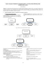
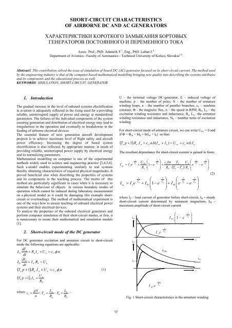
Fig. 1 Short-<strong>circuit</strong> <strong>char<strong>ac</strong>teristics</strong> in the armature winding<br />
t<br />
T a<br />
⎞<br />
⎟<br />
⎟<br />
⎠<br />
t<br />
t<br />
I Or
From the equation it follows that the currecnt consists <strong>of</strong> three<br />
components corresponding to the three parts <strong>of</strong> the right side <strong>of</strong> the<br />
equation. The first component is dependable on the generator load<br />
current before <strong>short</strong>-<strong>circuit</strong>, the second component on the remanent<br />
magnetism <strong>and</strong> the third one on the value <strong>of</strong> the current in the<br />
excitation <strong>circuit</strong>. Components behaviour is ilustrated in Fig. 1.<br />
The corresponding computer model <strong>of</strong> DC-generator was assembled<br />
in the Simulink environment using st<strong>and</strong>ard blocks with the<br />
following basic parameters <strong>of</strong> the DC-generator:<br />
P n = 9 kW, U n = 28,5 V, I a = 400A, I b = 6A n = 4500 ot/min, R a =<br />
0,024 Ω, R b = 3,5 Ω, L a = 2,8.10-5 H, L b = 0,1 H , N = 228z, p = 3,<br />
a = 3, c e = 0,00038, U rem = 1,4V.<br />
Ik [A]<br />
800<br />
700<br />
600<br />
500<br />
400<br />
300<br />
200<br />
100<br />
0<br />
0<br />
0.05<br />
cas [s]<br />
0.1 3.5<br />
Ik= fnc(t)<br />
4<br />
Rb [ohm]<br />
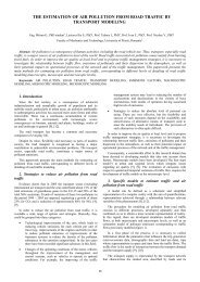
Fig. 2 Resulting simulated behaviour <strong>of</strong> <strong>short</strong>-<strong>circuit</strong> current in the<br />
DC-generator armature<br />
Ik [A]<br />
1200<br />
1000<br />
800<br />
600<br />
400<br />
200<br />
0<br />
0 0.02 0.04 0.06 0.08 0.1 4000<br />
cas [s]<br />
Ik= fnc(t)<br />
5000<br />
n [ot/min]<br />
4.5<br />
6000<br />
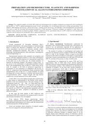
Fig. 3 The influence <strong>of</strong> changes in the selected parameters <strong>of</strong> the<br />
generator - the excitation winding resistance <strong>and</strong> RPM - on the<br />
behaviour <strong>of</strong> the <strong>short</strong>-<strong>circuit</strong> current <strong>of</strong> the DC generator<br />
18<br />
The resulting simulated behaviour <strong>of</strong> the <strong>short</strong>-<strong>circuit</strong> current<br />
corresponds to the theoretical assumptions (Fig. 2). The <strong>short</strong><strong>circuit</strong><br />
current <strong>char<strong>ac</strong>teristics</strong> begins in zero, then rapidly re<strong>ac</strong>hes<br />
the maximum value <strong>of</strong> the <strong>short</strong>-<strong>circuit</strong> current at 790 A, in a period<br />
<strong>of</strong> 0,002s. The influences <strong>of</strong> the change in the selected parameters<br />
<strong>of</strong> the generator - the excitation winding resistance <strong>and</strong> the RPM -<br />
exerted on the behaviour <strong>of</strong> the <strong>short</strong>-<strong>circuit</strong> current is illustrated in<br />
Fig.3. Changing the resistance in the excitation <strong>circuit</strong> within the<br />
range <strong>of</strong> 3,5 Ω to 4,5 Ω, changes the maximum value <strong>of</strong> <strong>short</strong><strong>circuit</strong><br />
current. When R b value increases, the maximum value <strong>of</strong> the<br />
<strong>short</strong>-<strong>circuit</strong> current decreases. The increase in the RPM value rises<br />
the maximum value <strong>of</strong> the <strong>short</strong>-<strong>circuit</strong> current.<br />
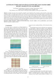
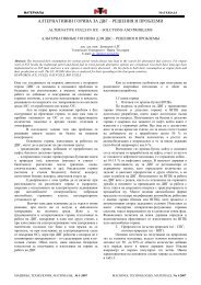
3. Short-<strong>circuit</strong> mode <strong>of</strong> the AC generator<br />
Similar appro<strong>ac</strong>h can be adopted also at identifying the AC<br />
generator <strong>and</strong> its subsequent analysis <strong>of</strong> its <strong>char<strong>ac</strong>teristics</strong> when in<br />
<strong>short</strong>-<strong>circuit</strong> mode. The <strong>short</strong>-<strong>circuit</strong> current in the stator winding is<br />
made up <strong>of</strong> two components: the alternative ia <strong>and</strong> the direct current<br />
id [2]. The resulting time behaviour <strong>of</strong> the <strong>short</strong>-<strong>circuit</strong> current is<br />
illustrated in Fig. 4 <strong>and</strong> the simulated <strong>char<strong>ac</strong>teristics</strong> <strong>of</strong> the<br />
individual components for the <strong>airborne</strong> generator GT-40 PČ6 are in<br />
Fig. 5.<br />
Fig. 4 Behaviour <strong>of</strong> the AC-generator phasing <strong>short</strong>-<strong>circuit</strong> current<br />
4. Conclusion<br />
Time behaviours <strong>of</strong> individual quantities can be monitored when<br />
changing the given input parameters. Simulated behaviours enable<br />
description <strong>of</strong> the basic attributes <strong>of</strong> the generator <strong>and</strong> their changes<br />
when introducing corresponding changes to input parameters.<br />
The models designed are adjusted to the te<strong>ac</strong>hing requirements <strong>of</strong><br />
the given problem. Higher efficiency in applying the results <strong>of</strong><br />
simulation experiments in te<strong>ac</strong>hing, calls for their finalization in<br />
terms <strong>of</strong> did<strong>ac</strong>tics, with the aim to establish an inter<strong>ac</strong>tive<br />
environment enabling optimum presentation <strong>of</strong> the aquired data<br />
<strong>ac</strong>quired as in view <strong>of</strong> the requirements <strong>of</strong> the given subject.
i11d<br />
i1a<br />
250<br />
200<br />
150<br />
100<br />
50<br />
0<br />
-50<br />
-100<br />
-150<br />
-200<br />
-250<br />
0 0.02 0.04 0.06 0.08<br />
cas<br />
0.1 0.12 0.14 0.16<br />
800<br />
700<br />
600<br />
500<br />
400<br />
300<br />
200<br />
100<br />
0<br />
0 0.05 0.1 0.15 0.2<br />
cas<br />
0.25 0.3 0.35 0.4<br />
Fig. 5 Simulated behaviours <strong>of</strong> transient AC <strong>and</strong> DC components<br />
<strong>of</strong> the stator current<br />
5. References<br />
[1] Adamčík, F.: Matematické a simulačné modely vybraných<br />
obvodov palubných systémov napájania elektrickou energiou. VLA<br />
Košice, 2004. ISBN 80-7166-045-0.<br />
[2] Bertinov, A. I.: Avi<strong>ac</strong>ionnyje električeskije generatory. GIOP,<br />
Moskva, 1959.<br />
[3] Sopata, M. - Soták, M. - Bréda, R.: Modelovanie a simulácia z<br />
pohľadu verifikácie a validácie. Nové trendy v rozvoji letectva.<br />
Zborník 6. medzinárodnej konferencie. Košice, Vojenská letecká<br />
akadémia GMRŠ, 2004. s. 28-33. ISBN 80-7166-050-7.<br />
[4] Jalovecký, R. Onboard systems <strong>of</strong> flight control 2 (in Czech).<br />
Brno : University <strong>of</strong> Defence, 2008. 93 p. ISBN 978-80-7231-593-2<br />
[5] Dub, M. Aircraft electrical equipment 1. Brno : University <strong>of</strong><br />
Defence, 2008. 105 p. ISBN 978-80-7231-591-8.<br />
[6] Kelemen, M. <strong>and</strong> Gregorzewski, M. <strong>and</strong> Olejník, F. Aviation<br />
education <strong>and</strong> training open to modern challenges. Acta Avionica,<br />
2005, Vol. 7, no. 11, p. 97 – 100.<br />
19