

Ph.D. Thesis - Physics
Ph.D. Thesis - Physics
Ph.D. Thesis - Physics

You also want an ePaper? Increase the reach of your titles
YUMPU automatically turns print PDFs into web optimized ePapers that Google loves.
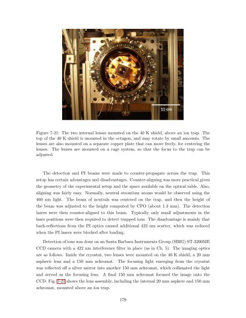
Figure 7-21: The two internal lenses mounted on the 40 K shield, above an ion trap. The<br />
top of the 40 K shield is mounted in the octagon, and may rotate by small amounts. The<br />
lenses are also mounted on a separate copper plate that can move freely, for centering the<br />
lenses. The lenses are mounted on a cage system, so that the focus to the trap can be<br />
adjusted.<br />
The detection and PI beams were made to counter-propagate across the trap. This<br />
setup has certain advantages and disadvantages. Counter-aligning was more practical given<br />
the geometry of the experimental setup and the space available on the optical table. Also,<br />
aligning was fairly easy. Normally, neutral strontium atoms would be observed using the<br />
460 nm light. The beam of neutrals was centered on the trap, and then the height of<br />
the beam was adjusted to the height computed by CPO (about 1.3 mm). The detection<br />
lasers were then counter-aligned to this beam. Typically only small adjustments in the<br />
laser positions were then required to detect trapped ions. The disadvantage is mainly that<br />
back-reflections from the PI optics caused additional 422 nm scatter, which was reduced<br />
when the PI lasers were blocked after loading.<br />
Detection of ions was done on an Santa Barbara Instruments Group (SBIG) ST-3200ME<br />
CCD camera with a 422 nm interference filter in place (as in Ch. 5). The imaging optics<br />
are as follows. Inside the cryostat, two lenses were mounted on the 40 K shield, a 20 mm<br />
aspheric lens and a 150 mm achromat. The focusing light emerging from the cryostat<br />
was reflected off a silver mirror into another 150 mm achromat, which collimated the light<br />
and served as the focusing lens. A final 150 mm achromat focused the image onto the<br />
CCD. Fig. 7-21 shows the lens assembly, including the internal 20 mm asphere and 150 mm<br />
achromat, mounted above an ion trap.<br />
179


