

Ph.D. Thesis - Physics
Ph.D. Thesis - Physics
Ph.D. Thesis - Physics

Create successful ePaper yourself
Turn your PDF publications into a flip-book with our unique Google optimized e-Paper software.
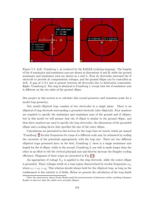
Figure 7-1: Left: Uraniborg 1, as rendered by the EAGLE scripting language. The lengths<br />
of the rf semimajor and semiminor axes are shown as dimensions A and B, while the ground<br />
semimajor and semiminor axes are shown as a and b. Four dc electrodes surround the rf<br />
electrode to provide dc compensation voltages, and the ground ellipse can be controlled as<br />
well. A gap of ≈ 0.1 mm is present between all electrodes due to fabrication constraints.<br />
Right: Uraniborg 2. The trap is identical to Uraniborg 1, except that the rf semiminor axis<br />
is different on the two sides of the ground ellipse.<br />
Our project in this section is to calculate this crystal geometry and transition point for a<br />
model trap geometry.<br />
Our model elliptical trap consists of two electrodes in a single plane. There is an<br />
elliptical rf ring electrode surrounding a grounded electrode (also elliptical). Four numbers<br />
are required to specify the semimajor and semiminor axes of the ground and rf ellipses,<br />
but in this model we will assume that the rf ellipse is similar to the ground ellipse, and<br />
thus three numbers are used to specify the trap electrodes: the dimensions of the grounded<br />
ellipse and a scaling factor that specifies the size of the outer ellipse.<br />
Calculations are presented in this section for the traps that we tested, which are named<br />
“Uraniborg.” 1 Secular frequencies for traps of a different scale may be estimated by scaling<br />
the curvature of the potentials appropriately with the trap size. There are two different<br />
elliptical traps presented here; in the first, Uraniborg 1, there is a single semiminor axis<br />
length for the rf ellipse, while in the second, Uraniborg 2, one side is made longer than the<br />
other in an effort to tilt the vertical principal axis and thereby increase the Doppler cooling<br />
efficiency. Diagrams of these traps are presented in Fig. 7-1.<br />
An appropriate rf voltage Vrf is applied to the ring electrode, while the center ellipse<br />
is grounded. These voltages result in a trap region characterized by secular frequencies ωˆn,<br />
where ωˆz = ωˆx + ωˆy. This relation should always hold for the elliptical trap, as long as the<br />
confinement is due entirely to rf fields. Below we present the calculation of the trap depth<br />
1 After the observatory where Tycho Brahe made his measurements of planetary orbits, enabling Johannes<br />
Kepler to discover that the orbits were actually ellipses.<br />
153


