Ph.D. Thesis - Physics
Ph.D. Thesis - Physics
Ph.D. Thesis - Physics
You also want an ePaper? Increase the reach of your titles
YUMPU automatically turns print PDFs into web optimized ePapers that Google loves.
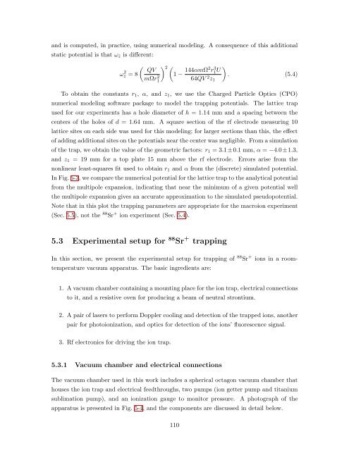
and is computed, in practice, using numerical modeling. A consequence of this additional<br />
static potential is that ωˆz is different:<br />
ω 2 ˆz<br />
<br />
QV<br />
= 8<br />
mΩr2 2 <br />
1 −<br />
1<br />
144αmΩ2r3 1U 64QV 2 <br />
. (5.4)<br />
z1<br />
To obtain the constants r1, α, and z1, we use the Charged Particle Optics (CPO)<br />
numerical modeling software package to model the trapping potentials. The lattice trap<br />
used for our experiments has a hole diameter of h = 1.14 mm and a spacing between the<br />
centers of the holes of d = 1.64 mm. A square section of the rf electrode measuring 10<br />
lattice sites on each side was used for this modeling; for larger sections than this, the effect<br />
of adding additional sites on the potentials near the center was negligible. From a simulation<br />
of the trap, we obtain the value of the geometric factors: r1 = 3.1±0.1 mm, α = −4.0±1.3,<br />
and z1 = 19 mm for a top plate 15 mm above the rf electrode. Errors arise from the<br />
nonlinear least-squares fit used to obtain r1 and α from the (discrete) simulated potential.<br />
In Fig. 5-3, we compare the numerical potential for the lattice trap to the analytical potential<br />
from the multipole expansion, indicating that near the minimum of a given potential well<br />
the multipole expansion gives an accurate approximation to the simulated pseudopotential.<br />
Note that in this plot the trapping parameters are appropriate for the macroion experiment<br />
(Sec. 5.5), not the 88 Sr + ion experiment (Sec. 5.4).<br />
5.3 Experimental setup for 88 Sr + trapping<br />
In this section, we present the experimental setup for trapping of 88 Sr + ions in a room-<br />
temperature vacuum apparatus. The basic ingredients are:<br />
1. A vacuum chamber containing a mounting place for the ion trap, electrical connections<br />
to it, and a resistive oven for producing a beam of neutral strontium.<br />
2. A pair of lasers to perform Doppler cooling and detection of the trapped ions, another<br />
pair for photoionization, and optics for detection of the ions’ fluorescence signal.<br />
3. Rf electronics for driving the ion trap.<br />
5.3.1 Vacuum chamber and electrical connections<br />
The vacuum chamber used in this work includes a spherical octagon vacuum chamber that<br />
houses the ion trap and electrical feedthroughs, two pumps (ion getter pump and titanium<br />
sublimation pump), and an ionization gauge to monitor pressure. A photograph of the<br />
apparatus is presented in Fig. 5-4, and the components are discussed in detail below.<br />
110


