Exaggeration of Facial Features in Caricaturing
Exaggeration of Facial Features in Caricaturing
Exaggeration of Facial Features in Caricaturing

Create successful ePaper yourself
Turn your PDF publications into a flip-book with our unique Google optimized e-Paper software.
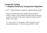
3 System Implementation<br />
3.1 Input Picture<br />
Input Picture<br />
Manually Mark<strong>in</strong>g<br />
Decide Exaggerated<br />
<strong>Facial</strong> <strong>Features</strong><br />
<strong>Exaggeration</strong><br />
Layer Render<strong>in</strong>g<br />
Result<br />
Figure 2. System flow chart<br />
Our system needs a digital picture <strong>of</strong> a human face as its<br />
<strong>in</strong>put file. While we are tak<strong>in</strong>g that picture, the model’s face<br />
must be turned toward his right side about forty-five degrees.<br />
The reason is that the features are more three-D at this angle,<br />
especially the nose, and so will make exaggerated features<br />
pop up. If the model’s face faces us directly, we won’t know<br />
whether his or her nose is snub-nosed or not, whether his or<br />
her cheekbone is prom<strong>in</strong>ent or not, etc.<br />
3.2 Manually Mark<strong>in</strong>g<br />
In fetch<strong>in</strong>g the <strong>in</strong>formation <strong>of</strong> facial features, such as the<br />
shape and the position, we manually mark key po<strong>in</strong>ts on the<br />
<strong>in</strong>put picture. We separate those facial features <strong>in</strong>to seven<br />
parts: the right brow, the left brow, the right eye, the left eye,<br />
the nose, the mouth, and the rest <strong>of</strong> face. The outl<strong>in</strong>e <strong>of</strong> each<br />
part is composed <strong>of</strong> several key po<strong>in</strong>ts. For <strong>in</strong>stance, we<br />
need seventeen key po<strong>in</strong>ts to constitute the outl<strong>in</strong>e <strong>of</strong> a face<br />
and we need eleven key po<strong>in</strong>ts to constitute the outl<strong>in</strong>e <strong>of</strong> a<br />
mouth.<br />
Take a right eye for example. After a user manually marks<br />
the twelve key po<strong>in</strong>ts <strong>of</strong> the eye, our system can draw the<br />
outl<strong>in</strong>e <strong>of</strong> a right eye by connect<strong>in</strong>g them <strong>in</strong> the form <strong>of</strong> a<br />
Bezier curve. An example <strong>of</strong> the key po<strong>in</strong>ts <strong>of</strong> a right eye is<br />
shown <strong>in</strong> Figure 3. Each pair <strong>of</strong> neighbor<strong>in</strong>g po<strong>in</strong>ts<br />
constructs a Bezier curve. We have found the basic rules <strong>of</strong><br />
every <strong>in</strong>dividual Bezier curve so that the result is close to the<br />
actual outl<strong>in</strong>e no matter what k<strong>in</strong>d <strong>of</strong> right eyes are<br />
simulated.<br />
We choose the way <strong>of</strong> connect<strong>in</strong>g key po<strong>in</strong>ts <strong>in</strong>stead <strong>of</strong><br />
trac<strong>in</strong>g along the actual outl<strong>in</strong>e. The reason is that it is faster<br />
and easier to manipulate later. When we want to change the<br />
shape <strong>of</strong> the right eye, we only need to recalculate those key<br />
po<strong>in</strong>ts’ locations and apply the same functions <strong>of</strong> the Bezier<br />
curve. But if we choose to trace along the actual outl<strong>in</strong>e,<br />
every time we want to change the shape, we have to<br />
recalculate the whole function <strong>of</strong> the Bezier curve. It will<br />
take a lot <strong>of</strong> time and is too complicated.<br />
Figure 3. Left: Orig<strong>in</strong>al pictures. Right: Marked with key po<strong>in</strong>ts (yellow, blue) and control po<strong>in</strong>ts (red).