troubleshooting for relief valves used in hydraulic systems
troubleshooting for relief valves used in hydraulic systems
troubleshooting for relief valves used in hydraulic systems

Create successful ePaper yourself
Turn your PDF publications into a flip-book with our unique Google optimized e-Paper software.
TROUBLESHOOTING FOR RELIEF VALVES USED IN HYDRAULIC SYSTEMS<br />
Prof. Dr. M. Sc. Pancar Yasar 1 , Assoc. Prof. Dr. M. Sc. Ergur H. Sevil 1<br />
Faculty of Mechanical Eng<strong>in</strong>eer<strong>in</strong>g – Eskisehir Osmangazi University, Eskisehir 1 , Turkey.<br />
Abstract: This study relates to the description of a <strong>relief</strong> valve briefly and <strong>troubleshoot<strong>in</strong>g</strong> due to pressure rise <strong>in</strong> <strong>hydraulic</strong> system. In any<br />
<strong>hydraulic</strong> system, it is essential to limit the maximum pressure generated by the constant displacement pump. For this purpose, usually<br />
pressure <strong>relief</strong> valve is <strong>used</strong> and pressure across the <strong>relief</strong> valve can be balanced. Many of the failures <strong>in</strong> a <strong>hydraulic</strong> system show similar<br />
symptoms such as, a gradual or sudden loss of high pressure, result<strong>in</strong>g <strong>in</strong> loss of power or speed <strong>in</strong> the cyl<strong>in</strong>ders. Due to possible<br />
malfuntions, the cyl<strong>in</strong>ders may stall under light loads or may not move at all. Often the loss of power is accompanied by an <strong>in</strong>crease <strong>in</strong><br />
pressure which must be taken away by a <strong>relief</strong> valve.<br />
Keywords: TROUBLESHOOTING, RELIEF VALVE, PRESSURE-SENSITIVE VALVE, HYDRAULIC SYSTEM.<br />
1. Introduction<br />
It is believed that the French scientist Denis Pap<strong>in</strong> was the <strong>in</strong>ventor<br />
of the safety valve at the end of the seventeenth century. The safety<br />
valve was kept closed by means of either a spr<strong>in</strong>g or a lever and a<br />
movable weight; slid<strong>in</strong>g the weight along the lever to regulate the<br />
pressure. Some believe that, Pap<strong>in</strong> was only the <strong>in</strong>ventor of some<br />
improvements and that safety <strong>valves</strong> were already be<strong>in</strong>g <strong>used</strong> some 50<br />
years earlier on a steam digester designed by Rudolf Glauber, a German-<br />
Dutch alchemist. Timothy Hackworth developed an open-ended safety<br />
valve <strong>for</strong> the steam tra<strong>in</strong>s and boilers that were first be<strong>in</strong>g built around<br />
1830 when the start<strong>in</strong>g of the safety valve designs as we use today [1].<br />
Hydraulic <strong>systems</strong> are <strong>used</strong> <strong>in</strong> so many automatic mach<strong>in</strong>es. It is<br />
equipped with a pressure <strong>relief</strong> valve to ma<strong>in</strong>ta<strong>in</strong> the operation pressure<br />
of the system at a pre-determ<strong>in</strong>ed level. Relief valve protects the<br />
<strong>hydraulic</strong> pump and <strong>in</strong> turn the prime mover from overload quickly <strong>in</strong><br />
case the system is exposed to overpressure. That’s why, characteristics<br />
of such a valve like the other system components are very important <strong>in</strong><br />
design<strong>in</strong>g the <strong>hydraulic</strong> system. The basic pressure <strong>relief</strong> valve is<br />
dynamically undesirable due to relatively low viscous damp<strong>in</strong>g. This<br />
k<strong>in</strong>d of valve provides low damp<strong>in</strong>g dur<strong>in</strong>g upward movement of the<br />
<strong>relief</strong> valve arbor [2].<br />
Pressure <strong>relief</strong> <strong>valves</strong> <strong>used</strong> <strong>in</strong> <strong>hydraulic</strong> <strong>systems</strong> are spr<strong>in</strong>g-loaded<br />
<strong>valves</strong> designed to open and relieve excess pressure, then immediately<br />
close, prevent<strong>in</strong>g any loss of flow of fluid after normal conditions have<br />
been renovated [3]. They are designed and manufactured to act as a<br />
safety measure <strong>in</strong> pressurized liquid system. The <strong>relief</strong> valve is a device<br />
utilized to divert excess pressure (sudden surges) <strong>in</strong> the discharge side of<br />
the pump <strong>in</strong>to the suction side. Generally, these changes are so rapidly<br />
and of such magnitude, that the pump operator can not correct quickly<br />
enough. The properly set and ma<strong>in</strong>ta<strong>in</strong>ed <strong>relief</strong> valve can make these<br />
corrections <strong>for</strong> the operator [4].<br />
The pressure <strong>relief</strong> valve shall safely control <strong>in</strong>crease <strong>in</strong> pressure by<br />
vent<strong>in</strong>g the pressurized liquid from the location. Another application is<br />
to protect equipment from overpressure. The <strong>valves</strong> are generally “backpressure<br />
dependent”, so can be discharged to atmosphere easily. Once a<br />
valve has discharged, replacement is usually adviced, as the set pressure<br />
can no longer be guaranteed. It is recommended to have a <strong>relief</strong> valve<br />
pressure sett<strong>in</strong>g at least 25% higher than the maximum system operat<strong>in</strong>g<br />
pressure. One must be sure that set pressure should not be higher than<br />
the design pressure of the <strong>hydraulic</strong> system [5].<br />
2. Description of Relief Valves Design<br />
A historic <strong>in</strong>troduction to the pressure <strong>relief</strong> valve evolution leads to<br />
the def<strong>in</strong>ition of the best per<strong>for</strong>mance characteristic of pressure <strong>relief</strong><br />
<strong>valves</strong>. The salient features of the valve's best per<strong>for</strong>mance characteristic<br />
as a comb<strong>in</strong>ation of the valve ‘best dynamic per<strong>for</strong>mance’ and the valve<br />
‘best discharge capacity’ and factors lead<strong>in</strong>g to distortions of the best<br />
per<strong>for</strong>mance characteristics [6].<br />
Relief <strong>valves</strong> are classified <strong>in</strong> two types. In the direct act<strong>in</strong>g type, the<br />
pressure to be relieved acts directly on the fluid regulat<strong>in</strong>g element. This<br />
type is commonly employed <strong>in</strong> <strong>systems</strong> with relatively low flow rates.<br />
For high flow rates, a pilot operated type is commonly employed. In this<br />
type the pressure to be controlled acts on a pilot. As soon as this pilot<br />
allows flow, the pressure difference across the ma<strong>in</strong> regulat<strong>in</strong>g element<br />
19<br />
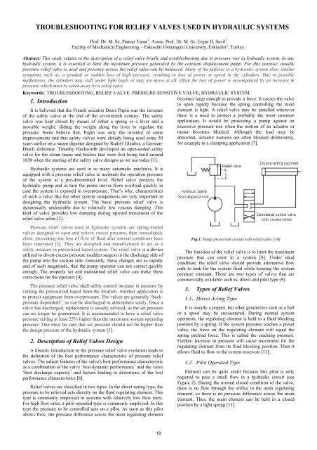
becomes large enough to provide a <strong>for</strong>ce. It causes the valve<br />
to open rapidly because the spr<strong>in</strong>g controll<strong>in</strong>g the ma<strong>in</strong><br />
element is light. A <strong>relief</strong> valve may be <strong>in</strong>stalled wherever<br />
there is a need to protect a probably the most common<br />
application. It would be protect<strong>in</strong>g a pump aga<strong>in</strong>st an<br />
excessive pressure rise when the motion of an actuator or<br />
motor becomes blocked. Although the load may be<br />
abnormal, actuator motions are often blocked deliberately,<br />
<strong>for</strong> example <strong>in</strong> a clamp<strong>in</strong>g application [7].<br />
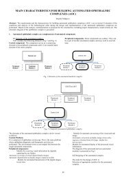
Fig.1. Pump protection circuit with <strong>relief</strong> valve [10]<br />
The function of the <strong>relief</strong> valve is to limit the maximum<br />
pressure that can exist <strong>in</strong> a system [8]. Under ideal<br />
condition, the <strong>relief</strong> valve should provide alternative flow<br />
path to tank <strong>for</strong> the system fluid while keep<strong>in</strong>g the system<br />
pressure constant. There are two types of <strong>valves</strong> that are<br />
commercially available such as, direct and pilot type (9).<br />
3. Types of Relief Valves<br />
3.1. Direct Act<strong>in</strong>g Type<br />
It is usually a poppet, but other geometries such as a ball<br />
or a spool may be encountered. Dur<strong>in</strong>g normal system<br />
operation, the regulat<strong>in</strong>g element is held <strong>in</strong> a fluid block<strong>in</strong>g<br />
position by a spr<strong>in</strong>g. If the system pressure reaches a preset<br />
value, the <strong>for</strong>ce on the regulat<strong>in</strong>g element will equal the<br />
spr<strong>in</strong>g preload <strong>for</strong>ce. This is called the crack<strong>in</strong>g pressure.<br />
Further, <strong>in</strong>crease <strong>in</strong> pressure will cause movement <strong>for</strong> the<br />
regulat<strong>in</strong>g element from its fluid block<strong>in</strong>g position. Then it<br />
allows fluid to flow to the system reservoir [11].<br />
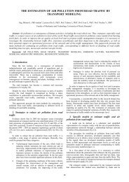
3.2. Pilot Operated Type<br />
Element can be quite small because this pilot is only<br />
required to pass a small flow <strong>in</strong> a <strong>hydraulic</strong> circuit (see<br />
Figure 2). Dur<strong>in</strong>g the normal closed condition of the valve,<br />
there is no flow through the orifice <strong>in</strong> the ma<strong>in</strong> regulat<strong>in</strong>g<br />
element, so there is no pressure difference across the ma<strong>in</strong><br />
element. Thus, the ma<strong>in</strong> element can be held <strong>in</strong> a closed<br />
position by a light spr<strong>in</strong>g [11].
Fig.2. Basic types of <strong>relief</strong> <strong>valves</strong> <strong>for</strong> different operations [5]<br />
4. Operation of Relief Valves <strong>in</strong> Hydraulic Systems<br />
The mach<strong>in</strong>e tolerances are critical and even a small amount of dirt<br />
can cause the <strong>relief</strong> valve system to malfunction. A good preventive<br />
ma<strong>in</strong>tenance program is essential to prevent the problems <strong>in</strong> <strong>relief</strong> valve<br />
system. It is important to realize that <strong>for</strong> the <strong>relief</strong> valve to function<br />
properly, the discharge pressure should be at least 3-4 bar greater than<br />
the suction or <strong>in</strong>com<strong>in</strong>g pressure. If not, the <strong>relief</strong> valve opens but the<br />
fluid will not be able to flow from the discharge to the suction area.<br />
It is a common fallacy of some pump operators to th<strong>in</strong>k the <strong>in</strong>stalled<br />
<strong>relief</strong> <strong>valves</strong> protect them under all conditions. Normal <strong>relief</strong> valve<br />
<strong>systems</strong> cannot relieve discharge pressure below the <strong>in</strong>com<strong>in</strong>g or suction<br />
side pressure. Surges such as those encountered <strong>in</strong> a relay operation, if<br />
not controlled, it will be transmitted to the discharge side of the pump. If<br />
companies get <strong>in</strong>volved <strong>in</strong> relay operations over 3 bar, a suction side<br />
<strong>relief</strong> valve must be <strong>in</strong>stalled [12]. These are usually a one-piece unit<br />
(entirely separate from those previously discussed) <strong>in</strong> which pre-settt<strong>in</strong>g<br />
the pressure by adjust<strong>in</strong>g a spr<strong>in</strong>g-loaded valve. When the pressure rises<br />
above the sett<strong>in</strong>g level, the valve opens and dumps the fluid to the tank.<br />
This cont<strong>in</strong>ues up to the pressure drops below the preset pressure.<br />
Without a suction-type <strong>relief</strong> valve you are risk<strong>in</strong>g the possibility of<br />
excess pressure crack<strong>in</strong>g the pump body or, even worse, the <strong>in</strong>ability of<br />
your eng<strong>in</strong>eer to be able fully to control discharge pressure.<br />
A conventional pressure <strong>relief</strong> valve is to be designed to open at a<br />
preset liquid pressure. A spr<strong>in</strong>g exerts a <strong>for</strong>ce on a valve seat via a piston<br />
assembly. At the set pressure, the piston beg<strong>in</strong>s to lift result<strong>in</strong>g <strong>in</strong> a small<br />
amount of flow through the valve and the pressure <strong>for</strong>ce. This <strong>for</strong>ce acts<br />
on the piston that <strong>in</strong>creases importantly, and overcomes the spr<strong>in</strong>g <strong>for</strong>ce.<br />
The imbalance of <strong>for</strong>ces cause the valve to fully open. By design, the<br />
difference <strong>in</strong> pressure from the valve set po<strong>in</strong>t to the fully open condition<br />
is no more than 10 %. The valve then re-closes at a pressure where the<br />
spr<strong>in</strong>g <strong>for</strong>ce overcomes the piston <strong>for</strong>ce. Under normal system operat<strong>in</strong>g<br />
conditions, the pressure at the valve <strong>in</strong>let is below the set pressure. Only<br />
under abnormal operat<strong>in</strong>g conditions should the pressure <strong>relief</strong> valve be<br />
open [12]. The reasons <strong>for</strong> the usage of <strong>relief</strong> <strong>valves</strong> are listed below.<br />
(1) Protect system operators<br />
(2) Prevent the demolotion of capital <strong>in</strong>vestment<br />
(3) Preserve the production<br />
(4) Reduc<strong>in</strong>g downtime of the system<br />
(5) Comply with codes and standards<br />
(6) Protect the environment<br />
In the daily operation of <strong>hydraulic</strong> system overpressure can happen<br />
due to <strong>in</strong>cidents like a blocked discharge, fire exposure, tube rupture,<br />
check valve failure. This can lead to a major <strong>in</strong>cident <strong>in</strong> plant if the<br />
pressure <strong>relief</strong> system is not <strong>in</strong> place or not functional. It is very<br />
important to properly select, size, locate and ma<strong>in</strong>ta<strong>in</strong> the pressure <strong>relief</strong><br />
<strong>systems</strong> to prevent or m<strong>in</strong>imize the losses from major <strong>in</strong>cident like fire<br />
or other issues [2].<br />
4.1. Causes of overpressure<br />
Overpressure is significant <strong>in</strong> prelim<strong>in</strong>ary steps of pressure <strong>relief</strong><br />
system design. It helps the designer to understand the cause of<br />
overpressure and m<strong>in</strong>imize the effect. It is the result of an unbalance or<br />
disruption of the normal flows of material and energy that causes the<br />
material or energy, or both, to build up <strong>in</strong> some part of the system.<br />
4.1.1 Blocked Discharge<br />
Blocked discharge can be expla<strong>in</strong>ed at any system, pump or other<br />
equipment is the closure of blockage at outlet either by mechanical<br />
20<br />
failure or human error. This exposes the system to a pressure<br />
that exceeds the maximum allowable work<strong>in</strong>g pressure. So,<br />
the <strong>relief</strong> valve is required unless adm<strong>in</strong>istrative procedures<br />
to control valve closure.<br />
4.1.2. Fire Exposure<br />
Fire may occur <strong>in</strong> <strong>hydraulic</strong> <strong>systems</strong>. So, all<br />
equipments must be protected from overpressure which is<br />
controlled by pressure <strong>relief</strong> <strong>valves</strong>.<br />
4.1.3. Check Valve Failure<br />
It is generally placed at a pump outlet. Malfunction of<br />
the check valve can lead to overpressure <strong>in</strong> <strong>hydraulic</strong><br />
system. When a fluid is pumped <strong>in</strong>to a system, failure of the<br />
check valve causes reversal of the liquid flow back to pump.<br />
When the liquid is displaced <strong>in</strong>to a suction system and high<br />
pressurizied fluid enters, overpressure is occured.<br />
4.1.4. Thermal Expansion<br />
If isolation of a pip<strong>in</strong>g on the cold side of system can<br />
result <strong>in</strong> overpressure due to heat <strong>in</strong>put from the warm side,<br />
then the l<strong>in</strong>e or cold side of the system must be protected by<br />
a <strong>relief</strong> valve [12]. Hydraulic <strong>systems</strong> <strong>for</strong> the pressure<br />
protection, follow<strong>in</strong>g categorization can be <strong>used</strong> <strong>for</strong> the<br />
product standards especially <strong>in</strong> EU countries.<br />
EN ISO 4126-1: Presssure safety <strong>relief</strong> <strong>valves</strong><br />
EN ISO 4126-2: Burst<strong>in</strong>g disc safety devices<br />
EN ISO 4126-3: Safety <strong>valves</strong> and burst<strong>in</strong>g disc safety<br />
devices <strong>in</strong> comb<strong>in</strong>ation<br />
EN ISO 4126-4: Pilot operated safety <strong>valves</strong><br />
EN ISO 4126-5: Controlled safety pressure <strong>relief</strong> <strong>systems</strong><br />
EN ISO 4126-6: Application, selection and <strong>in</strong>stallation of<br />
burst<strong>in</strong>g disc safety devices<br />
DIN EN 12953-8: Shell boilers, safety devices aga<strong>in</strong>st<br />
excessive presssure<br />
DIN EN 764-7: Siz<strong>in</strong>g and spr<strong>in</strong>g-Sett<strong>in</strong>g<br />
4.2. Troubleshoot<strong>in</strong>g the <strong>relief</strong> <strong>valves</strong><br />
Listed below are the areas that you can troubleshoot the<br />
<strong>relief</strong> <strong>valves</strong> [7]. When work<strong>in</strong>g on a specific mach<strong>in</strong>e <strong>for</strong><br />
more <strong>in</strong><strong>for</strong>mation technical manual is prefered.<br />
If low or erratic pressure occurs <strong>for</strong> the sake of<br />
<strong>troubleshoot<strong>in</strong>g</strong>, the follow<strong>in</strong>g items must be<br />
considered.<br />
Adjustment is <strong>in</strong>correct.<br />
Dirt, chip, or burrs may cause the valve partially<br />
open.<br />
Poppets or seats may be worned or damaged.<br />
Valve piston <strong>in</strong> the ma<strong>in</strong> body may be sticked.<br />
Selection of spr<strong>in</strong>g is wrong<br />
Spr<strong>in</strong>g ends may be damaged.<br />
Valve <strong>in</strong> the body may be cocked.<br />
Orifice or balance hold may be blocked.<br />
If <strong>relief</strong> valve has no pressure, the follow<strong>in</strong>g items must<br />
be considered.<br />
Orifice or balance hole may be plugged.<br />
Poppet does not seat.<br />
Valve may have a loose fit.<br />
Spr<strong>in</strong>g may be broken.<br />
Dirt, chip, or burrs may cause the the valve<br />
partially open.<br />
Poppet or seat may be worned or damaged.<br />
Valve <strong>in</strong> the body may be cocked.<br />
If excessive noise occurs consider the follow<strong>in</strong>g items;
Oil viscosity may be too high.<br />
Poppet or seat may be faulty or worned.<br />
L<strong>in</strong>e pressure may have an excessive return.<br />
Pressure sett<strong>in</strong>g is too close to that of another valve <strong>in</strong> the<br />
circuit.<br />
Spr<strong>in</strong>g may be broken.<br />
If adjustment of the <strong>relief</strong> valve can not be achieved properly,<br />
consider the follow<strong>in</strong>g items;<br />
Spr<strong>in</strong>g may be broken.<br />
Fatique <strong>for</strong> spr<strong>in</strong>g material may come across.<br />
Improper spr<strong>in</strong>g may have been <strong>used</strong>.<br />
Dra<strong>in</strong> l<strong>in</strong>e <strong>in</strong> system may be restricted.<br />
4. 3. Relief Valve Failures and Remedies<br />
Hydraulic <strong>valves</strong> are precision-made and must be very accurate <strong>in</strong><br />
controll<strong>in</strong>g a fluid pressure, direction, and volume with<strong>in</strong> a <strong>hydraulic</strong><br />
system. Contam<strong>in</strong>ants, such as dirt, <strong>in</strong> the oil are the major problems <strong>in</strong><br />
valve failures. Small amounts of dirt, l<strong>in</strong>t, rust, or sludge can cause<br />
annoy<strong>in</strong>g malfunctions and extensively damage valve parts. Such<br />
material will cause a valve to stick, plug small open<strong>in</strong>gs, or abrade the<br />
mat<strong>in</strong>g surfaces until a valve leaks. Only the specified oils must be <strong>used</strong><br />
<strong>in</strong> a <strong>hydraulic</strong> system.<br />
Follow<strong>in</strong>g recommendations are advisable be<strong>for</strong>e servic<strong>in</strong>g a <strong>relief</strong><br />
valve [1].<br />
Disconnect the electrical power source be<strong>for</strong>e remov<strong>in</strong>g a<br />
<strong>hydraulic</strong> <strong>relief</strong> valve's components.<br />
Release the system's <strong>hydraulic</strong> pressure be<strong>for</strong>e disconnect<strong>in</strong>g<br />
any <strong>hydraulic</strong> valve components.<br />
Lower all <strong>hydraulic</strong> work<strong>in</strong>g units to the ground be<strong>for</strong>e<br />
disconnect<strong>in</strong>g any parts.<br />
Clean a valve and its surround<strong>in</strong>g area be<strong>for</strong>e remov<strong>in</strong>g any<br />
part <strong>for</strong> service.<br />
Pa<strong>in</strong>t th<strong>in</strong>ner or acetone <strong>for</strong> clean<strong>in</strong>g is not advisable.<br />
Fig.3. Troubleshoot<strong>in</strong>g nomogram <strong>for</strong> <strong>hydraulic</strong> system with <strong>relief</strong> valve<br />
The follow<strong>in</strong>g must be fulfilled when disassembl<strong>in</strong>g a valve.<br />
Ma<strong>in</strong>tenance operator must be certa<strong>in</strong> that all tools are clean<br />
and free of grease and dirt.<br />
One must be careful to identify the parts when disassembl<strong>in</strong>g<br />
<strong>for</strong> later reassembly. The valve sections to be reassembled <strong>in</strong> the same<br />
order.<br />
If possible, use a vise equipped with lead or brass jaws, or<br />
protect the component by wrapp<strong>in</strong>g component <strong>in</strong> a protective cover<strong>in</strong>g.<br />
Seal<strong>in</strong>g all the valve's hous<strong>in</strong>g open<strong>in</strong>gs to remove the<br />
components dur<strong>in</strong>g service work is advisable.<br />
21<br />
If the shut down <strong>for</strong> pressurized equipment is reduced,<br />
the <strong>in</strong>tervals between <strong>relief</strong> valve exam<strong>in</strong>ations need to be<br />
similarly extended, or <strong>systems</strong> developed to allow the<br />
exam<strong>in</strong>ations to be carried out on-l<strong>in</strong>e [13]. Besides these<br />
above mentioned remedies, we also use Figure 3 <strong>in</strong> order to<br />
troubleshoot the problem aris<strong>in</strong>g <strong>in</strong> <strong>relief</strong> <strong>valves</strong> [14].<br />
5. Conclusion<br />
As with all <strong>troubleshoot<strong>in</strong>g</strong> techniques, knowledge of<br />
components and their function <strong>in</strong> a system is vitally<br />
important. It is probably fair to say that, when all the<br />
components of a <strong>hydraulic</strong> system have been identified, their<br />
function determ<strong>in</strong>ed and the operation of the system as a<br />
whole understood, the troubleshooter has gone 51% of the<br />
way towards f<strong>in</strong>d<strong>in</strong>g the problem. It is important to make the<br />
use of advices given <strong>for</strong> <strong>relief</strong> <strong>valves</strong> effectively, a good<br />
understand<strong>in</strong>g of the basic pr<strong>in</strong>ciples of <strong>relief</strong> <strong>valves</strong> with a<br />
knowledge of the operation and application of them.<br />
Hydraulic <strong>systems</strong> are gett<strong>in</strong>g more and more complex<br />
as methods of controll<strong>in</strong>g mach<strong>in</strong>es become <strong>in</strong>creas<strong>in</strong>gly<br />
developed. Technological advances <strong>in</strong> many <strong>hydraulic</strong><br />
system components such as, <strong>relief</strong> <strong>valves</strong> were exhibited <strong>in</strong><br />
the last twenty years. The object of this study is to provide<br />
procedure <strong>for</strong> a logical approach on <strong>troubleshoot<strong>in</strong>g</strong> which<br />
can be extended when necessary to cover specific mach<strong>in</strong>es<br />
<strong>in</strong> all areas of <strong>in</strong>dustry either us<strong>in</strong>g the advices or flow charts<br />
given. In order to control pressure of flow, the fundamentals<br />
<strong>for</strong> this procedure must be developed.<br />
The ma<strong>in</strong> problem <strong>in</strong> philosophy of the <strong>troubleshoot<strong>in</strong>g</strong><br />
procedure is determ<strong>in</strong><strong>in</strong>g the aspects of the <strong>hydraulic</strong><br />
system, such as fault, flow, pressure or direction. By<br />
consult<strong>in</strong>g the circuit diagram, a list of possible causes can<br />
be drawn up. The next stage is to search <strong>for</strong> the obvious<br />
remedy. Certa<strong>in</strong> controls that are achieved on a <strong>hydraulic</strong><br />
system us<strong>in</strong>g the human senses of sight, touch and hear<strong>in</strong>g<br />
which can be carried out very quickly.<br />
6. References<br />
[1] M. Hellemans, The Safety Relief Valve Handbook, Design and<br />
Use of Process Safety Valves to ASME and International Codes<br />
and Standards, (1st edition, Macmillan Company, 2009).<br />
[2] J. Watton, The Design of a S<strong>in</strong>gle-Stage Relief Valve with<br />
Directional Damp<strong>in</strong>g, The Journal of Fluid Control Includ<strong>in</strong>g<br />
Fluidics Vol. 18, n. 2, pp. 22–35, 1988.<br />
[3] K. Dasgrupta, R. Karmakar, Modell<strong>in</strong>g and Dynamics of S<strong>in</strong>gle-<br />
Stage Pressure Relief Valve with Directional Damp<strong>in</strong>g,<br />
Simulation Modell<strong>in</strong>g Practise and Theory, Vol. 10, n. 1-2, pp.<br />
51-67, 2002.<br />
[4] www.haleproducts.com.<br />
[5] Y. Pancar, H.S. Ergur, Hydraulic Circuits, Design and<br />
Application, (Lecture notes, ESOGU, Eng. Faculty, Mech. Eng.<br />
Dept., 2009).<br />
[6] N. G. Gavrila, S. Sethi, Best Per<strong>for</strong>mance Characteristic of<br />
Pressure Relief Valves and The Amount of Lost Product, Journal<br />
of Loss Prevention <strong>in</strong> the Process Industries, Vol. 4, n. 4, pp.<br />
265-271, 1991.<br />
[7] F. C. Parry, Relief System Handbook, (Institution of Chemical<br />
Eng<strong>in</strong>eers, ICE, 1992).<br />
[8] K. Dasgupta, R. Karmakar, Dynamic Analysis of Pilot Operated<br />
Pressure Relief Valve, Simulation Modell<strong>in</strong>g Practice and Theory<br />
Vol. 10, pp. 35–49, 2002.<br />
[9] A. Misra, K. Behd<strong>in</strong>anb, W.L. Cleghorna, Self-Excited Vibration<br />
of a Control Valve due to Fuid–Structure Interaction, Journal of<br />
Fluids and Structures Vol. 16, n. 5, pp. 649-665, 2002.<br />
[10] S. Hayashi, K. Ohi, Global Stability of a Poppet Valve Circuit,<br />
Journal of Fluid Control, Vol. 21, n. 4, pp. 48-63. 1999.<br />
[11] J. S. Cundiff, Fluid Power Circuits and Controls, (1st edition,<br />
CRC Pres LLC, 2002).<br />
[12] www.grothcorp.com<br />
[13] T. Nicholls, Benefits of On-l<strong>in</strong>e Relief Valve Test<strong>in</strong>g, World<br />
Pumps, Vol. 2004, n. 456, pp. 50-54, 2004.<br />
[14] Guide to Industrial Hydraulics, Ma<strong>in</strong>tanence Manual, (Vickers,<br />
1998)