

Experiments with Supersonic Beams as a Source of Cold Atoms
Experiments with Supersonic Beams as a Source of Cold Atoms
Experiments with Supersonic Beams as a Source of Cold Atoms

Create successful ePaper yourself
Turn your PDF publications into a flip-book with our unique Google optimized e-Paper software.
HeNe<br />
M2<br />
M1<br />
BB<br />
/2 L<br />
BB<br />
PC coil PC PD<br />
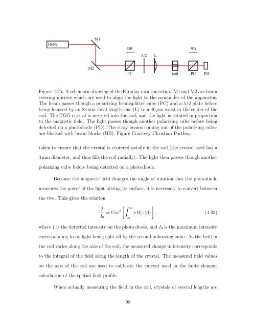
Figure 4.25: A schematic drawing <strong>of</strong> the Faraday rotation setup. M1 and M2 are beam<br />
steering mirrors which are used to align the light to the remainder <strong>of</strong> the apparatus.<br />
The beam p<strong>as</strong>ses though a polarizing beamsplitter cube (PC) and a λ/2 plate before<br />
being focused by an 83 mm focal length lens (L) to a 40 μm waist in the center <strong>of</strong> the<br />
coil. The TGG crystal is inserted into the coil, and the light is rotated in proportion<br />
to the magnetic field. The light p<strong>as</strong>ses though another polarizing cube before being<br />
detected on a photodiode (PD). The stray beams coming out <strong>of</strong> the polarizing cubes<br />
are blocked <strong>with</strong> beam blocks (BB). Figure Courtesy Christian Parthey.<br />
taken to ensure that the crystal is centered axially in the coil (the crystal used h<strong>as</strong> a<br />
3 mm diameter, and thus fills the coil radially). The light then p<strong>as</strong>ses though another<br />
polarizing cube before being detected on a photodiode.<br />
Because the magnetic field changes the angle <strong>of</strong> rotation, but the photodiode<br />
me<strong>as</strong>ures the power <strong>of</strong> the light hitting its surface, it is necessary to convert between<br />
the two. This gives the relation<br />
I<br />
I0<br />
=Cos 2<br />
z2<br />
z1<br />
<br />
vB(z)dz , (4.33)<br />
where I is the detected intensity on the photo diode, and I0 is the maximum intensity<br />
corresponding to no light being split <strong>of</strong>f by the second polarizing cube. As the field in<br />
the coil varies along the axis <strong>of</strong> the coil, the me<strong>as</strong>ured change in intensity corresponds<br />
to the integral <strong>of</strong> the field along the length <strong>of</strong> the crystal. The me<strong>as</strong>ured field values<br />
on the axis <strong>of</strong> the coil are used to calibrate the current used in the finite element<br />
calculation <strong>of</strong> the spatial field pr<strong>of</strong>ile.<br />
When actually me<strong>as</strong>uring the field in the coil, crystals <strong>of</strong> several lengths are<br />
98


