THE SHOESTRING RACER
THE SHOESTRING RACER
THE SHOESTRING RACER

Create successful ePaper yourself
Turn your PDF publications into a flip-book with our unique Google optimized e-Paper software.
CONSTRUCTION<br />
BY PAT TRITLE<br />
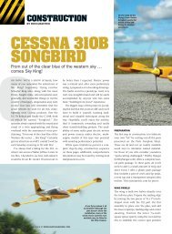
<strong>THE</strong><br />
<strong>SHOESTRING</strong><br />
<strong>RACER</strong><br />
A scale backyard pylon racer<br />
<strong>THE</strong> YELLOW AND RED <strong>SHOESTRING</strong> has<br />
always been one of my favorite airplanes<br />
and over the years, I’ve built several freeflight<br />
and U-control versions, all of which<br />
were great flyers. A few years ago, I started<br />
thinking about building a small RC Shoestring<br />
in a Speed 400-size. With the growing<br />
popularity of brushless motors and LiPo<br />
battery technology being what it is, I<br />
decided to forge ahead.<br />
I designed the Shoestring so it could be<br />
built and flown by modelers with intermediate<br />
building and piloting skills while still<br />
being a good representation of the full-scale<br />
Shoestring. The result is a very stable, reasonably<br />
fast, all-sheet balsa model that’s a<br />
pure joy to fly! I’ve tried everything I can to<br />
make the airplane “snap” out of a turn and<br />
determined that it just won’t. Its stall is<br />
more of a “mush” and it still maintains<br />
aileron control all the way down the speed<br />
range.<br />
82 MORE FROM THIS ISSUE AT MODELAIRPLANENEWS.COM<br />
The model was designed around the 6V<br />
Speed 400 motor and is controlled by only<br />
elevator and aileron. Hand-launching is<br />
easy, as there is plenty of fuselage to hold.<br />
Landings are done 3-point, so the fixed tailwheel<br />
keeps a good straight line during the<br />
short rollout; if you’re flying onto grass, just<br />
plop it in! Though the model has a good roll<br />
rate, the aileron input isn’t twitchy at the<br />
center at all. Even with the CG balance<br />
point moved aft, the elevator never gets<br />
“goosey.” When the CG is moved too far<br />
aft, the model just doesn’t come up on step.<br />
All in all, it’s a good, solid, honest airplane<br />
that I recommend to anyone who’s entering<br />
the wonderful world of little airplanes.<br />
BUILDING <strong>THE</strong> FUSELAGE<br />
As always with a model of this type, it must<br />
be built light. I built my prototype using<br />
hand-selected balsa, but using the contestgrade<br />
stuff will only help if you’re really<br />
FREE PULLOUT<br />
PLAN IN THIS ISSUE!<br />
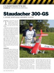
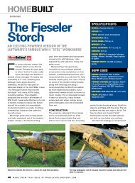
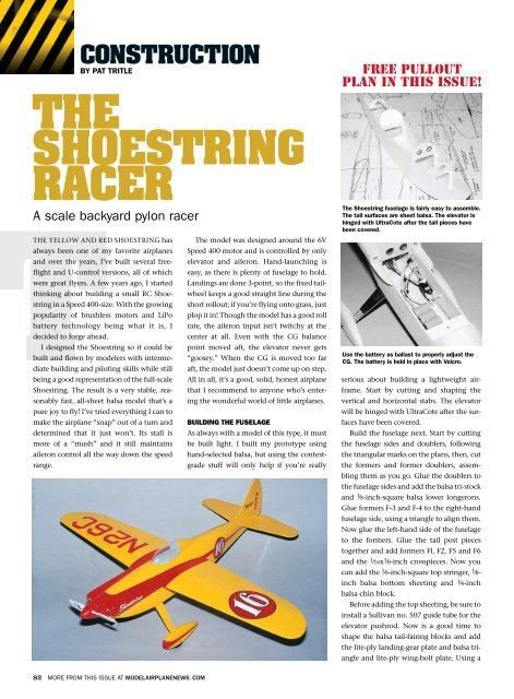
The Shoestring fuselage is fairly easy to assemble.<br />
The tail surfaces are sheet balsa. The elevator is<br />
hinged with UltraCote after the tail pieces have<br />
been covered.<br />
Use the battery as ballast to properly adjust the<br />
CG. The battery is held in place with Velcro.<br />
serious about building a lightweight air-<br />
frame. Start by cutting and shaping the<br />
vertical and horizontal stabs. The elevator<br />
will be hinged with UltraCote after the surfaces<br />
have been covered.<br />
Build the fuselage next. Start by cutting<br />
the fuselage sides and doublers, following<br />
the triangular marks on the plans, then, cut<br />
the formers and former doublers, assembling<br />
them as you go. Glue the doublers to<br />
the fuselage sides and add the balsa tri-stock<br />
and 1 ⁄8-inch-square balsa lower longerons.<br />
Glue formers F-3 and F-4 to the right-hand<br />
fuselage side, using a triangle to align them.<br />
Now glue the left-hand side of the fuselage<br />
to the formers. Glue the tail post pieces<br />
together and add formers Fl, F2, F5 and F6<br />
and the 1 ⁄16x1 ⁄8-inch crosspieces. Now you<br />
can add the 1 ⁄8-inch-square top stringer, 1 ⁄8inch<br />
balsa bottom sheeting and 1 ⁄4-inch<br />
balsa chin block.<br />
Before adding the top sheeting, be sure to<br />
install a Sullivan no. 507 guide tube for the<br />
elevator pushrod. Now is a good time to<br />
shape the balsa tail-fairing blocks and add<br />
the lite-ply landing-gear plate and balsa triangle<br />
and lite-ply wing-bolt plate. Using a
Sig 1 ⁄16 x l x l0-inch landing gear blank, drill<br />
and shape the gear as shown on the plans.<br />
Drill and tap the plate for the 8-32 bolts and<br />
attach the landing gear. Now cut out,<br />
assemble and shape the wheel pants to<br />
complete the basic fuselage.<br />
BUILDING <strong>THE</strong> WING<br />
Building the wing really isn’t difficult, but<br />
the dihedral is built into the bottom skin, so<br />
use the dihedral/washout jigs shown on the<br />
plans to ensure proper alignment. Start by<br />
joining together five, 1 ⁄16x3x32-inch-long<br />
balsa sheets. Cut out the lower skin to the<br />
size shown on the plan. The top one should<br />
be slightly oversize to compensate for the<br />
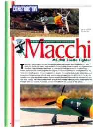
The dihedral is built into the bottom wing skin by<br />
using the jigs shown on the plans. The ailerons are<br />
controlled via the torque tubes; be sure they fit<br />
well before you glue them into place.<br />
curvature. Cut the ribs out of the scraps.<br />
Using the plans, mark the position of all the<br />
ribs and the aileron spars.<br />
Using a sanding block, taper the top of<br />
the lower trailing edge (TE) to the contour<br />
shown on the rib templates. Now carefully<br />
score the skin under ribs Rl, and gently<br />
“crack” it to form the dihedral. Cut the<br />
balsa leading edge (LE) and glue it into<br />
place. Next, cut the 1 ⁄16-inch balsa R5 and<br />
R6 tip doublers and glue them into place.<br />
Add ribs R2 and R4 and glue the 1 ⁄8-inch<br />
balsa hinge spars into place followed by R3<br />
and the aileron ribs. Build up a left and right<br />
washout jig using the patterns on the plans,<br />
and position them under rib R4 and align<br />
them to the TE. Using scrap balsa, shim the<br />
LE so it doesn’t bow when the upper skin<br />
goes on. Now glue the Rl ribs into place.<br />
Add the balsa filler in the center section at<br />
the LE and TE.<br />
Slip the 3 ⁄32-inch aluminum torque rod<br />
tubes over some 1 ⁄16-inch music wire, and<br />
bend the torque rod wires to shape. Cut<br />
down Du-Bro 2-56 threaded couplers and<br />
solder them to the tops of the torque rods.<br />
Spend a little time fitting the torque rods to<br />
ensure smooth, non-binding operation<br />
before you glue into place. Locate the outlet<br />
slots for the vertical parts of the torque<br />
SPECIFICATIONS<br />
MODEL: Shoestring<br />
TYPE: electric sport-scale<br />
WINGSPAN: 30.5 in.<br />
LENGTH: 28.5 in.<br />
WING AREA: 165 sq. in.<br />
FLYING WEIGHT: 16 to 18 oz.<br />
RADIO REQ’D: 3-channel (throttle,<br />
elevator and aileron)<br />
POWER: 6V Speed 400 motor with<br />
Sprite XLR BEC controller, 500AR 7-cell<br />
battery and Aeronaut 6.5x4 prop<br />
CONTROL THROWS<br />
ELEVATOR: ± 5 ⁄16 in.<br />
AILERON: ± 3 ⁄16 in.<br />
rods and cut them into the upper skin.<br />
Carefully align and test-fit the skin to the<br />
wing. When you’re sure that everything fits<br />
properly, lay the skin aside while you use a<br />
pin to poke holes around the aileron outline<br />
through the bottom skin. This will<br />
make cutting the aileron out of the wing a<br />
lot easier later.<br />
Finally, inspect the wing assembly one<br />
more time before gluing the upper skin into<br />
place with medium CA. After the glue has<br />
dried, remove the wing from the board and<br />
sand it to shape. Carefully cut the ailerons,<br />
and shape them for hinging.<br />
ATTACHING <strong>THE</strong> WING<br />
Find and mark the centerline of the wing<br />
MAY 2010 83
<strong>THE</strong> <strong>SHOESTRING</strong> <strong>RACER</strong><br />
and align it to the fuselage. Using a piece of<br />
1 ⁄8-inch O.D. brass tube, reach into the<br />
front opening of the fuselage and mark the<br />
LE through the dowel hole in F-3. Remove<br />
the wing, drill a 1 ⁄8-inch hole at the mark<br />
and glue the dowel into place. Glue the<br />
plywood blind nut plate to the wing, and<br />
drill a 1 ⁄8-inch hole through the wing. Reinstall<br />
the wing on the fuselage and with the<br />
wing properly aligned, drill a 3 ⁄32-inch hole<br />
into the bolt plate. Remove the wing again<br />
and, with a piece of music wire in the holddown<br />
plate hole, punch through the<br />
fuselage bottom. Open the hole to 1 ⁄4 inch<br />
and line it up with the bolt plate using a<br />
paper tube.<br />
Now reinstall the wing, push the 3 ⁄4-inch-<br />
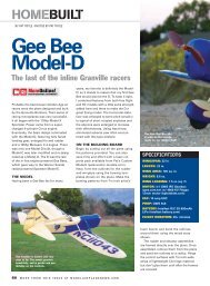
The aileron servo is attached to the center of the<br />
Shoestring wing, which is attached to the fuselage<br />
with a 3 ⁄4-inch-long 4-40 bolt and blind nut.<br />
long 4-40 bolt through the wing, add a<br />
blind nut and turn it until it’s just snug.<br />
Note that the blind nut won’t be aligned<br />
with the upper surface of the wing. Use a<br />
dab of 5-minute epoxy to glue the nut and<br />
fill the gaps.<br />
Now it’s time to install the aileron servo<br />
and linkage. Make sure that the aileron<br />
installation is correct before you close the<br />
model up, as it becomes inaccessible when<br />
the model is finished. I’m not crazy about<br />
doing it this way, but the torque rods on the<br />
bottom won’t allow adequate battery clearance.<br />
When you’re satisfied with the<br />
installation, glue formers F3A, B and C into<br />
place along with the 1 ⁄8-inch-square centerline<br />
stringer. Remove the wing from the<br />
fuselage and sheet the center section with<br />
1 ⁄16-inch balsa. Build up the cheek cowls<br />
from light 1 ⁄4-inch thick balsa, and roughshape<br />
and hollow them before you glue<br />
them into place. I used Micro Fill to feather<br />
everything after assembly.<br />
84 MORE FROM THIS ISSUE AT MODELAIRPLANENEWS.COM<br />
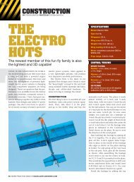
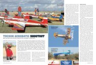
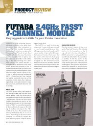
Bob Downey runs up the Shoestring Racer’s<br />
engine in preparation for the next heat. (Photo<br />
courtesy of the Air Age Media archives)<br />
RODNEY’S <strong>RACER</strong><br />
Rodney Kreimendahl, the designer of the full-size ‘Shoestring” racer, made his<br />
home in Westfield, Massachusetts. As a young man, Rodney was an avid<br />
modeler and greatly influenced by the exploits of Charles Lindberg. He loved<br />
airplanes, but never became a pilot. After high school, he did not attend college<br />
(even though he won a scholarship to Northeastern University) and later became a<br />
draftsman for Chance-Vought. Prior to WW II, he was recruited by the Lockheed Aircraft<br />
Corporation, as a structural designer where he worked on the boom design for<br />
Lockheed’s YP-38 project.<br />
Before the War, the Cleveland Air Races was the biggest event for aviation<br />
enthusiasts. In 1947 a new class of air racers was started called the Goodyear class.<br />
Often referred to as the “midget class,” this class as an alternative to the very<br />
expensive Unlimited race class. The new class had specific airframe requirements and a<br />
max engine displacement of 190ci. With its 188ci displacement, the 85hp, 4-cylinder, aircooled<br />
Continental engine was the engine of choice and it quickly became the standard<br />
Goodyear powerplant.<br />
Lockheed started a design team to develop a plane for this class, which eventually<br />
became known as “The Cosmic Wind.” Since there was plenty of interest in race planes<br />
at the time, Rodney started another team where he did most of the design work for a<br />
new racer. Rodney’s wife was asked to name his new midget racer and she came up with<br />
“Shoestring”—since the airplane had been built on a shoestring budget. Each of the<br />
design team’s members chipped in a dollar each week during the plane’s construction<br />
and it was eventually finished minus the single most expensive item—the engine. The<br />
Shoestring made its first flight in 1949, powered by a loaner engine acquired from race<br />
pilot Bob Downey. After the Shoestring project, Rodney went on to work on other<br />
Lockheed projects including the X-7 (an unmanned test bed for ramjet engines) the F-104<br />
Starfighter, the vertical takeoff XFV-1 Salmon fighter and the U-2 spy plane, the project<br />
he was working on when he was killed in a plane crash.<br />
In 1965, an airline pilot named Ray Cote bought the original Shoestring aircraft and<br />
with the help of Carl Ast and Paul Jones, he started an extensive modification program<br />
for the plane. The Shoestring was Ray’s first racer and in his 16 years of ownership, he<br />
won 41 races (including nine national championships!) before he retired the plane to the<br />
San Diego Air Museum in 1981. The colors of the original Shoestring were Cadillac<br />
Chartreuse and Chinese Red.<br />
The highly modified 1970s-era<br />
Race 16 Shoestring as owned<br />
by Ray Cote.
<strong>THE</strong> <strong>SHOESTRING</strong> <strong>RACER</strong><br />
INSTALLING <strong>THE</strong> MOTOR<br />
Cut the motor mount out of 1 ⁄16-inch-thick<br />
ply and glue it to the front of the fuselage.<br />
The spinner you use will determine how<br />
thick a balsa ring you’ll need to glue to the<br />
front end to fair it in. Again, use Micro Fill<br />
to feather it all in.<br />
My prototype was powered with a 6V<br />
Speed 400 motor and a Sprite XLR BEC controller.<br />
The system was hard-wired using a<br />
Deans connector for the battery. An S-80<br />
servo was mounted to the right-hand fuselage<br />
side; my older 72MHz receiver was<br />
mounted on the other side. As always, I<br />
removed the case from the receiver for an<br />
additional weight savings, but there are<br />
now plenty of micro 2.4GHz receivers that<br />
will save even more space and weight.<br />
Finally, install the elevator control horn<br />
and Z-bend the 0.025-inch diameter music<br />
wire pushrod at the servo end and clip it<br />
extra long at the back end.<br />
COVERING AND FINAL ASSEMBLY<br />
Sand the airframe to remove any bumps or<br />
®<br />
<br />
hobbico.com/93y<br />
Distributed Exclusively Through<br />
GREAT PLANES ® MODEL DISTRIBUTORS COMPANY,<br />
P.O. BOX 9021, CHAMPAIGN, IL 61826-9021<br />
©2010 Hobbico ® , Inc. — 3074469<br />
boo-boos. I used EconoKote to cover and<br />
trim my model. The markings are decals<br />
from the old Carl Goldberg 42-inch-span<br />
Shoestring U-control kit. The canopy,<br />
landing gear and wheel pants were painted<br />
with dope.<br />
With all covering and trim completed,<br />
align and glue the tail section into place—<br />
don’t forget the tailwheel! Trim, fit and<br />
install the Sig 7-inch canopy, install the<br />
wheels on 4-40 bolt axles, and epoxy the<br />
wheel pants to the gear. Bolt the landing<br />
gear to the fuselage with two 8-32 nylon<br />
bolts. Using the battery location for ballast,<br />
balance the model as shown on the plans.<br />
Use a two-inch strip of Velcro to hold the<br />
battery in place. I used a 500AR 7-cell battery<br />
in a three over four stack. There is also<br />
plenty of room for any 3S 11.1V LiPo pack.<br />
FLYING <strong>THE</strong> <strong>SHOESTRING</strong><br />
Before your first launch, check the control<br />
throws. Install a fresh battery, run the<br />
motor up to full throttle and briskly<br />
hand-launch the model. It will lose about<br />
three feet of altitude while building up<br />
speed, but will soon settle into a nice<br />
groove. The best-looking turns are<br />
banked about 45 degrees, but knife-edge<br />
turns are great using just enough elevator<br />
to maintain altitude. Rolls, loops and<br />
stall-turns are great, even without a rudder.<br />
To get the stall turn, just pull up<br />
gently into the vertical line. As the airplane<br />
slows down, torque will take over<br />
and pull the nose around. As the plane<br />
breaks over the top, reduce the throttle<br />
and the nose will fall right through. It<br />
takes a little practice, but when you get it<br />
figured out, it works every time.<br />
After much testing, I’ve found the best<br />
balance between performance and duration<br />
was achieved using an Aeronaut 6.5x4<br />
prop. Static current draw is 13.2amps for<br />
about 110 watts on 7 cells. Duration is<br />
around 3 1 ⁄2 to 4 minutes using the 500AR<br />
cells. Of course, a brushless motor system<br />
and LiPo battery pack will provide more<br />
power and longer flight durations.<br />
Good luck and good racing!<br />
The new standard in receiver batteries.<br />
LiFeSource Lithium Iron Phosphate Batteries pack high energy<br />
density in a compact size — and they’re lightweight too!<br />
LiFeSource packs: the best of all battery worlds!<br />
Awesome power — plus over 1000 cycles with no drop in performance<br />
Nominal 6.6 volt rating — no regulators required<br />
Thermally stable — extremely resistant to heating<br />
Environmentally friendly — no cadmium, no cobalt, no toxic substances<br />
Multiple connectors — “plug-and-play” convenience and flexibility<br />
Four capacities (1100, 1800, 2100, 3200 mAh) — for aircraft<br />
applications where power and weight count!<br />
Find out more about LiFeSource batteries — go to hobbico.com!