by GIULIANO RAIMONDI THE WW II ITALIAN MACCHI MC.200 ...
by GIULIANO RAIMONDI THE WW II ITALIAN MACCHI MC.200 ...
by GIULIANO RAIMONDI THE WW II ITALIAN MACCHI MC.200 ...

Create successful ePaper yourself
Turn your PDF publications into a flip-book with our unique Google optimized e-Paper software.
y <strong>GIULIANO</strong><br />
<strong>RAIMONDI</strong><br />
<strong>THE</strong> <strong>WW</strong> <strong>II</strong> <strong>ITALIAN</strong> <strong>MACCHI</strong> <strong>MC.200</strong> Saetta fighter was my first serious attempt at a true<br />
scale R/C model. As usual, I was unable to find accurately drawn 3-views, so I produced my<br />
own from measurements I had made of a full-size aircraft at a museum. Powered <strong>by</strong> a<br />
Webra* Speed .61 and a 12x6 propeller, my original 1/6.5-scale model had no bad flight habits. All<br />
maneuvers including spins showed no problems despite the model's small, scale tail surfaces and<br />
its asymmetrical wing design (its left wing panel is slightly longer than its right one). In the air, the<br />
model proved to be very stable despite a gross weight of almost 10 pounds that resulted in a very<br />
high wing loading. This hefty loading made takeoffs and landings especially tricky and inspired me<br />
to begin work on a second, 1/5.2-scale version of the Macchi, the subject of this article.
<strong>ITALIAN</strong> STALLION ON CAD<br />
The plans took two years to develop and<br />
were CAD-designed. For the 1/5.2-scale<br />
model, the wingspan was increased to 79.9<br />
inches, and all control surfaces were<br />
designed to be removable. The unusual<br />
Left: the tall com<br />
ponents are to<br />
scale and rela-<br />
tively small but<br />
provide adequate<br />
control and sta<br />
bility. Note the<br />
plywood skin on<br />
the rudder; it sim-<br />
ulates the sheet-<br />
metal rib struc<br />
ture on the full-<br />
size Macchi<br />
<strong>MC.200</strong> Saetta.<br />
wing-fuselage separation allows the best-<br />
possible access to the fuel tank and radio<br />
equipment. In addition, there is no visible<br />
gap between the fuselage and the Karmann<br />
(wing root) fairing. Two circular panels<br />
hide the rear wing-retaining screws, and<br />
the forward screws are accessible from<br />
inside the wheel wells. The removable<br />
control surfaces allow easy painting and<br />
repairing. The functional engine-cowl<br />
cooling flaps work with the throttle-control<br />
linkage; the two small canopy-entry doors<br />
are also functional.<br />
Because this project is complex and the<br />
drawings are highly detailed, here I'll con<br />
centrate only on the important details.<br />
LANDING GEAR<br />
Start with the most demanding item—the<br />
landing gear; it's electrically driven and<br />
uses microswitches for travel stops. The<br />
geared motor drives two jackscrews with<br />
bevel gears: a diagonal strut that pulls the<br />
gear up is attached to the jackscrew with<br />
ball links. The gear rotates on and is<br />
supported <strong>by</strong> a long, chordwise-mounted<br />
steel tube in each wing panel. Balance<br />
springs help the gear retract into the<br />
"up" position. The struts use two coaxial<br />
springs of different lengths<br />
(the shorter one is stiffer)<br />
to absorb shock and the<br />
torque links (scissors) are<br />
functional and prevent the<br />
lower forks from rotat-<br />
The center "wing-to-fuselage" section is built<br />
as part of the wing's upper surface—an<br />
unusual design. It houses the retractable<br />
landing gear's drive mechanism. Four bolts<br />
hold the wing to the fuselage.<br />
ing—an amazingly effective arrangement.<br />
I made a pair of pretty hard landings, and<br />
the model didn't bounce at all. The land<br />
ing gear locks in the "up" position with<br />
spring-loaded hooks—a must in this kind<br />
of mechanism. The gear pistons and the<br />
rotation axles are made of medical-supply,<br />
stainless-steel tubes.<br />
Find the necessary hardware (the bevel<br />
gears are from model car accessories), then<br />
cut out of resin-impregnated Fiberglass (or<br />
similar stiff material) and drill the main "tri<br />
angle" that supports the jackscrew drive. If<br />
you can't machine the difficult shape of the<br />
wheel-supporting fork<br />
out of a solid block of<br />
aluminum, fashion it<br />
<strong>by</strong> bending sheet alu<br />
minum around a ply<br />
wood mold, then form<br />
the conical blending<br />
between the basic<br />
fork and the circular<br />
strut base using a liq<br />
uid-metal filler (J.B.<br />
Weld*). The torque<br />
links are made of<br />
Delrin plastic. The<br />
tailwheel has a double<br />
shock-absorber sys-<br />
SPECIFICATIONS<br />
Name: Macchi <strong>MC.200</strong> Saetta<br />
Type: 1/5.2-scale <strong>WW</strong> <strong>II</strong> Italian fighter<br />
Wingspan: 79.9 in.<br />
Weight 13.3 lb.<br />
Wing area: approx. 990 sq. in.<br />
Wing loading: 31 oz./sq. ft.<br />
Airfoil: sernisyrnmetrical<br />
Radio req'd: 6 channels (rudder, elevator,<br />
ailerons, throttle, retracts, flaps)<br />
Engine used: ASP 1.08 2-stroke<br />
Construction materials:<br />
balsa, plywood, pine, plastic,<br />
aluminum and stainless steel<br />
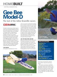
Features: the Macchi C.200<br />
is a precision scale model of<br />
the <strong>WW</strong> <strong>II</strong> Italian fighter and<br />
is built of balsa and plywood.<br />
The fuselage is built in<br />
horizontal halves directly<br />
over the plans and is planked<br />
with balsa sheeting. The flaps<br />
and ailerons are controlled<br />
with torque tubes, and the<br />
hinging is removable and<br />
scale. The 9-page, highly<br />
detailed construction plans<br />
(FSP12961) show every piece<br />
of the model including the<br />
scale, electrically driven<br />
retractable landing gear. All scale fittings,<br />
the cockpit interior and control<br />
surfaces are shown, as is a dummy,<br />
double-row radial engine. The functional<br />
engine-cowl cooling flaps are<br />
hinged; and the cockpit doors are<br />
also functional. The wing is the same<br />
as the full-size Macchi's; the left<br />
panel is slightly longer than the right.<br />
Washout is built into the wing, and<br />
building tabs are drawn on each rib.<br />
A set of five, full-size scale detail<br />
views (FSP12962) shows the top, left,<br />
right, front and bottom views, including<br />
rivet, screw and panel detail and<br />
insignia shape and position.<br />
[Editor's note: more photos of the<br />
Macchi are available from Bob<br />
Banka's Scale Model Research'.]<br />
Left: the<br />
electronically<br />
driven<br />
retractable<br />
landing gear<br />
Is shown here<br />
on the 1:6.5-<br />
scale version.<br />
The new<br />
1:S.2-scale<br />
version Is<br />
also scratch-<br />
built and is<br />
fully detailed<br />
on the plans.<br />
Some<br />
machining Is<br />
required.
These reduced drawings are representative of<br />
the scale details on the full-size drawings and<br />
plans. See page 83 of this month's Plans<br />
Directory to order the full-size plans (FSP12961<br />
and FSP12962), or call (800) 537-5874.
<strong>THE</strong> <strong>MACCHI</strong> <strong>MC.200</strong> SAETTA FIGHTER<br />
tem as in the full-size plane. You can. of<br />
course, simplify construction <strong>by</strong> building<br />
only one of the two shock-absorber systems<br />
shown on the plans.<br />
FUSELAGE<br />
The fuselage is built<br />
over the plans in<br />
halves joined<br />
along a hori<br />
zontal plane.<br />
It's important<br />
to keep the<br />
halves of the<br />
firewall per<br />
pendicular<br />
to the build<br />
ing board.<br />
Former F-18 is<br />
made of ply<br />
wood, and the<br />
completed tailwheel<br />
unit is attached to it.<br />
The aft tail cone is made<br />
out of a balsa block and is hol<br />
lowed out as shown on the plans.<br />
Apart from the cockpit interior (which I<br />
built and installed after I had joined the<br />
fuselage halves), the most annoying part<br />
of the fuselage construction is the "wing-<br />
to-fuselage" joining section; it's pretty<br />
unusual. Hoping that the plans are clear<br />
enough, my only suggestion is that you<br />
keep calm and be patient! The photos<br />
show the detail. This kind of arrangement<br />
gives the model a completely scale<br />
appearance. The radio-equipment layout<br />
shown on the plans is the best I could find;<br />
to minimize the nose-ballast requirement,<br />
keep the tail section as light as possible.<br />
The engine shown on the<br />
plans is an ASP* 1.8. It offers<br />
a good performance-to-price<br />
ratio, but of course, you can<br />
install other powerplants in<br />
the nose with minor modifi<br />
cations. There's enough room<br />
to accept a 2-cylinder, 1.60<br />
4-stroke. but some extra work<br />
on the firewall, dummy<br />
engine and engine bearers<br />
will be required.<br />
Before joining the fuselage<br />
halves, install all the<br />
pushrods and associated con<br />
trol linkages, including the receiver anten<br />
na-routing tube, and cut lightening holes<br />
in all balsa formers. Don't be afraid to cut<br />
these holes; the final epoxy-glass finish<br />
will add tremendous strength. If you aren't<br />
as crazy as I am, do the cockpit work now.<br />
or at least finish smooth the inner cockpit<br />
walls, and add the instrument panel.<br />
The vertical fin. rudder, hori-<br />
The dummy radial engine is<br />
made of thin aluminum<br />
sheet that has been<br />
painted black and has<br />
the lines scribed<br />
into It for effect.<br />
The ASP 1.08<br />
engine Is barely<br />
visible.<br />
zontal stab<br />
and eleva<br />
tors are<br />
also built in<br />
halves; first<br />
build and<br />
sheet the top<br />
half over the<br />
plans, then add<br />
the lower half of<br />
the ribs to complete<br />
the structure. The tail<br />
parts should give no prob<br />
lems; their construction is typical of<br />
other scale models. The plans show all<br />
half-rib patterns as well as some cross<br />
sections. The leading edges are formed<br />
with laminated balsa. Use lightweight<br />
balsa and very thin plywood where indi<br />
cated. Before you cut out the simulated<br />
rudder and elevator ribs, apply thinned<br />
epoxy to the plywood to strengthen the<br />
plywood and minimize the work needed<br />
later to seal and smooth the wood.<br />
has a longer left wing panel than the right<br />
(of course, the left aileron is a little longer<br />
than the right): my model duplicates this<br />
feature. The left wing panel has 17 ribs<br />
and the right. 16. The wing incidences are<br />
+ 1.5 degrees at rib l and zero at rib 16.<br />
The 1/8-inch-thick main spar is very easy<br />
to set up and is really strong, despite the<br />
longitudinal grain of the balsa section. To<br />
make construction easier, building tabs<br />
are included on the rib drawings. When<br />
you position rib 1, use the dihedral refer<br />
ence pattern provided on the plans. Note<br />
that the trailing edge of the inner section<br />
of each split flap is slightly curved, to<br />
blend into the shape of the lower<br />
Karmann fairing. The left wing panel is<br />
identical to the right, up to rib 16: then it<br />
has an additional rib, 17.<br />
The flaps and ailerons are actuated <strong>by</strong><br />
means of torque tubes—no visible hinges.<br />
The bases of the flaps are made of thin ply<br />
wood (0.4mm). Ribs can be made of ply or<br />
plastic, but it's easier to drill the many<br />
small lightening holes in plastic. If you<br />
select plywood, be sure to apply epoxy or<br />
CA before you saw and drill the holes. Cut<br />
the flap spar (torque tube) out of an alu<br />
minum tube. Also, cut the aileron torque<br />
tube (which runs through the flap's tube<br />
spar) out of a thin, stainless-steel medical<br />
tube. Close one end of the aileron tube<br />
Above: at the top Is the completed<br />
horizontal stab. Below It Is the<br />
double-row dummy radial engine<br />
and the finished vertical fin.<br />
Left: the ailerons and elevator<br />
are built In the same way as the<br />
rudder using plywood shims cut<br />
out to simulate the rib details.<br />
Here, you'll also see the engine-<br />
mount detail and the engine cowl<br />
with the dummy engine fitted<br />
into place on the original 1:6.5<br />
version.<br />
with a small piece of hardwood; you will<br />
insert the fiberglass actuating arm into this<br />
and seal it with glue. Close the other end of<br />
the aileron tube with a small block of<br />
brass. Solder it into place, then drill and
Below: the functional engine-cooling<br />
flaps are hinged; they are tied Into<br />
the throttle-control linkage.<br />
tap it at the correct angle in relation to the<br />
actuating arm. to accept the screw that<br />
ends with the ball-link control-linkage<br />
attachment. It is essential that the inner<br />
tube has no play at all in relation to the<br />
outer one. Remember: there are right and<br />
eft tubes. Cut the plywood flap base,<br />
apply thinned epoxy. and sand. Construct<br />
he hinges as shown on the plans. Cut out<br />
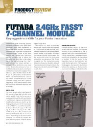
PREWAR <strong>MACCHI</strong><br />
Above: the completed fuselage with the engine cowl attached. The rocker-arm blisters<br />
attached to the cowl are made <strong>by</strong> forming sheet aluminum over plywood molds. Note<br />
the gun-sight glass in the finished cockpit.<br />
all ribs, and drill the holes for the torque<br />
tubes. After you insert the tube in the<br />
appropriate holes, position the ribs on the<br />
plywood base, and glue each to the base,<br />
but don't glue the ribs to the tube yet.<br />
Slide the tube into position, and fit the<br />
hinges between the appropriate ribs.<br />
Complete the Karmann fairing, then cut<br />
the flap opening in the bottom of the wing<br />
Faced with the problem of designing a new single-seat, cantilever low-wing fighter<br />
around the fairly low-powered Fiat A.74 RC.38 engine (rated at 840hp), Italian aircraft<br />
designers Macchi and Fiat came up with two fighters that looked very much<br />
alike. In fact, the superior airframe of the Macchi <strong>MC.200</strong> Saetta (Macchi design<br />
team for this project was led <strong>by</strong> Mario Castoldi) made it the faster of the two. The<br />
prototype was first flown on December 24. 1937; although it wasn't able to match<br />
the German, French and British designs of that time, the Regia Aeronautica ordered<br />
the <strong>MC.200</strong> into production as one of the replacements for the Fiat C.R. 32.<br />
When Italy entered <strong>WW</strong> <strong>II</strong>, 150 were built and delivered, but the final production<br />
number was around 1,000. Most were flown with open cockpits, and the A1 and A2<br />
versions were similar, but the A2 had a stronger wing that would carry heavier bomb<br />
loads. It first saw action in Malta and later in Greece, Russia and North Africa; its<br />
first real air opponent was the Hawker Hurricane. After seeing almost 10 years of<br />
service, it was eventually retired in 1947.<br />
SPECIFICATIONS<br />
Engine: Fiat A.74 RC.38 doublerow<br />
radial<br />
Span: 34 ft., 8 1/2 in.<br />
Length: 26 ft., 101/2 in.<br />
Max. weight: 5.132 lb.<br />
Max. level speed: 312.5mph<br />
Range: 540 miles<br />
Armament two 12.7mm Breda-<br />
SAFAT machine guns<br />
and the slots for the forward end of each<br />
hinge. Next, glue into place the plastic<br />
doubler that holds the inner end of each<br />
tube to the false rib. Assemble the flap <strong>by</strong><br />
first inserting the torque tube in the hole in<br />
the doubler, and then installing the two<br />
Some of the landing-gear parts and the lower<br />
gear door. A lot of metalwork is Involved.<br />
hinges in the wing slots. When you are sat<br />
isfied with their fit. remove them and apply<br />
slow-setting epoxy to the slots and to the<br />
hinges* fixed arms as well as to the tubes<br />
and the ribs. Slide the aileron torque tubes<br />
into the flap spar tube with the actuating<br />
arm on the correct side. Reattach them<br />
carefully, and align the<br />
trailing edges of the wing<br />
and the flap as well as the<br />
outer end of flap with the<br />
aileron cutout. Make sure<br />
the inner section of the flap<br />
trailing edge follows the<br />
shape of the Karmann fair<br />
ing. Hold the two trailing<br />
edges together <strong>by</strong> your<br />
favorite method, and go to<br />
bed until the epoxy cures.<br />
Aileron construction<br />
is simple, but pay atten<br />
tion while you position
<strong>THE</strong> <strong>MACCHI</strong> <strong>MC.200</strong> SAETTA FIGHTER<br />
Some of the sidewall cockpit detail<br />
was built separately and then added<br />
to the cockpit after the model had<br />
been completed.<br />
the plastic doubler at its root. The slot in<br />
the doubler must match with the actuating<br />
arm that is aligned with hinges' axis.<br />
Joining the aileron hinges to the wing is<br />
similar to attaching the flap. After the<br />
epoxy has cured, solder a small brass<br />
washer to the inner hinge pin, flush with<br />
the hinge side to prevent the aileron from<br />
moving laterally. You can make things<br />
easier <strong>by</strong> using commercial hinges for the<br />
ailerons, but I think that making those<br />
delicate, flapping things removable is<br />
worth the extra effort.<br />
SCALE FEATURES<br />
The engine cowl's rocker-arm blisters,<br />
cooling flaps, gear doors, canopy doors,<br />
cockpit floor, gear door support brackets,<br />
navigation-lights fairing and dummy cylinders<br />
are made of aluminum sheets of various<br />
thickness and stiffness, and they were<br />
cold-formed over wooden molds. The functional<br />
exhaust tubes are made from 0.1mm<br />
stainless steel. Except for the silk-covered<br />
ailerons, rudder and elevator, the finish is<br />
lightweight fiberglass cloth applied with<br />
thinned epoxy resin.<br />
All insignia, numbers,<br />
etc., were<br />
either sprayed on or<br />
hand-painted.<br />
The simulated,<br />
double-row radial<br />
engine was made<br />
in two parts: the<br />
forward row was<br />
glued to the cowl,<br />
and the aft one was<br />
attached to the<br />
engine bearers. Each cylinder was made<br />
of three sections cut out of thin aluminum<br />
and painted glossy black; then parallel<br />
lines were scratched onto them with a<br />
sharp point. When they had been bent to<br />
shape, they were contactcemented<br />
to the balsa-ply<br />
frame—time-consuming but<br />
easy and effective.<br />
FLYING<br />
Don't try to fly your model<br />
with the CG aft of the location<br />
shown on the plans. The very<br />
small scale stab/elevator section<br />
requires a more forward<br />
CG than usual. The Macchi<br />
<strong>MC.200</strong> Saetta is very stable,<br />
yet it has a quick, smooth<br />
response to every input. Of<br />
The cockpit detail is totally<br />
scale and finely appointed. The<br />
windshield frame was made of<br />
laminated wood, and the entry<br />
doors are hinged and functional.<br />
course, the model is fully aerobatic—just<br />
like the real thing! I even made it do the<br />
most beautiful spins (intentionally). On<br />
takeoff, I suggest that you use about 5<br />
degrees of flap and be ready to feed in<br />
more right rudder than usual; this requires<br />
some tail-dragger experience. The model is<br />
very responsive and has good control characteristics,<br />
right down to the stall. At slow<br />
speeds, the model has no tip-stall tendencies;<br />
the wing washout helps a lot. On<br />
landing, lowering the gear requires some<br />
up trim; otherwise, its behavior is like that<br />
of any good pattern plane. The model<br />
needs about 20 to 30 degrees of flap,<br />
which works well in calm conditions or a<br />
light wind; otherwise, keep it clean.<br />
For the controls throws, I would begin<br />
with these values:<br />
• elevator—15 degrees both up and down;<br />
• rudder—20 degrees left and right;<br />
• ailerons—12 degrees up and down.<br />
I also strongly recommend a gyro-assisted<br />
Giuliano's daughter Elena admires her father's handiwork.<br />
rudder for takeoff—at least for that first<br />
flight!<br />
If you want something a bit different in<br />
the way of scale <strong>WW</strong> <strong>II</strong> heavy metal, give<br />
this Italian stallion a try. The Macchi<br />
<strong>MC.200</strong> Saetta will please even the most<br />
jaded scale modeler. I wish you all "onepiece<br />
landings."<br />
* Addresses are listed alphabetically in the Index of<br />
Manufacturers on page 151. 4-<br />
About the author<br />
Born in Bologna, Italy, Giuliano Raimondi has<br />
been modeling off and on for nearly 32 years. He<br />
began in 1948 with small, rubber-powered models.<br />
In the '50s, he designed and built several<br />
control-line scale and aerobatic models, and in<br />
1968, he began in R/C. He received his pilot's<br />
license in 1956, ser\'ed with the Italian Air Force<br />
from '59 to '61, when he flew the Stinson L-5, T-6<br />
Texan, T-33 Thunderbird and the Fiat G-91.<br />
From '61 to '94, he served as captain instructor<br />
for Caravelle on Boeing 727s and 747s and on<br />
MD-80s. His total flight time is more than 15,000<br />
hours. He has also flown several sailplanes. His<br />
address is Largo Olgiata, 87/A2, 00123, Roma,<br />
Italy; email mc2489@mclink.it.
Scale TECHNIQUES<br />
<strong>by</strong> GEORGE LEU<br />
ZIROLI<br />
PLANS AND<br />
SHEETING<br />
WITH BALSA<br />
NICK ZIROLI and his son<br />
Nick Jr. have been designing<br />
planes and selling plans since<br />
I started to fly R/C in 1968. Their<br />
designs have always initiated trends in<br />
the hob<strong>by</strong> and. these days, they are<br />
leaders in giant-scale warbird design.<br />
Currently, their warbird plans<br />
include a Ju-87B Stuka, a P-47<br />
Thunderbolt, an F4U-1A Corsair, a<br />
P-51 Mustang, a P-38 Lightning, an<br />
AD-1 Skyraider and an F6F Hellcat to<br />
name just a few. All their plan sets are<br />
beautifully drawn and highly detailed.<br />
At many giant-scale warbird rallies.<br />
Ziroli designs dominate the field.<br />
To complement their plans, Nick<br />
Ziroli Plans* (owned <strong>by</strong> Nick Jr.)<br />
offers a number of giant-scale acces<br />
sories, including fiberglass fuselages,<br />
cowls, canopies, retracts, fuel lines,<br />
engines and modeling clamps. The<br />
Zirolis fly what they design, and<br />
they've both done very well at the<br />
Scale Masters and Top Gun. To find<br />
out more about giant warbirds, send<br />
$2 for their new catalogue.<br />
This Douglas Skyraider Is from Chuck<br />
Gill's The Aeroplane Works. The fiber-<br />
glass cowl, canopy and full-size plans are<br />
available from Nick Ziroli Plans.<br />
Nick Ziroli Sr. fuels up his newest warbird-the Douglas AD-1 Skyraider. Nick's equally<br />
Impressive P-38 Lightning is in the background. Both are available as kits from The<br />
Aeroplane Works.<br />
The Aeroplane Works*—operated<br />
<strong>by</strong> Chuck Gill and his sons. Mace and<br />
Keith—makes full kits of Nick Ziroli<br />
designs. They produce some of the<br />
finest wooden parts I've ever seen,<br />
and their attention to detail and over<br />
all kit quality<br />
is well beyond<br />
what I would<br />
expect from any<br />
manufacturer. I<br />
recently toured<br />
their facility, and<br />
I was impressed<br />
<strong>by</strong> their crafts<br />
manship and the<br />
pride they take in<br />
their products.<br />
Chuck and his<br />
sons not only cut<br />
wood and bend<br />
wires for the<br />
Ziroli plans, but<br />
they also work very closely with them<br />
to ensure that the wooden parts match<br />
those shown on the plans. Every kit that<br />
The Aeroplane Works produces has a<br />
money-back parts warranty.<br />
BALSA SHEETING<br />
Many would-be scale modelers shy<br />
away from airplanes that require a lot<br />
of balsa sheeting (e.g., warbirds).<br />
because they don't know how to apply<br />
balsa to curved surfaces. The follow<br />
ing technique for sheeting fins and sta<br />
bilizers should help create a true,<br />
warp-free surface.<br />
After building the part to be sheeted<br />
(in this case, a Hellcat vertical fin), I<br />
This flight box is new from The Aeroplane<br />
Works. Complete with power panel and fully<br />
charged batteries, the unit comes wired for<br />
12 and 24 volts, and It can even charge your<br />
glow-driver Ni-Cd.<br />
join the sheeting with Pica's* Glu-it to<br />
form one large sheet that's big enough<br />
to cover half of the part. 1 cut the piece<br />
so that it overlaps the fin <strong>by</strong> about<br />
1/2 inch all the way around, then<br />
I dampen the outside with a wet<br />
sponge. After a<br />
few minutes,<br />
when the out<br />
side grain has<br />
absorbed the<br />
water and starts<br />
to curve. I pin<br />
the sheet to<br />
both sides of<br />
the fin. To<br />
make it con<br />
form to the<br />
fin's shape, I<br />
hold it securely<br />
with a lot of<br />
straight pins,<br />
clothespins and<br />
tape, and then I let it dry overnight.<br />
When I remove the pins, etc., the sheet<br />
will retain the exact shape of the fin.<br />
Remove one side of the sheet and.<br />
using a ballpoint pen. trace the inter<br />
nal structure onto the inside of it.<br />
Remove that piece, and do the same<br />
for the other side. The outline acts as a<br />
gluing guide. Trim the sheet closer to<br />
the fin's shape, and glue it onto the<br />
fin. The sheet has been shaped, so the<br />
glue joints require fewer pins, etc. and<br />
the procedure is a lot easier than try<br />
ing to cover it in one sitting.<br />
• Suitable glues. For the first half of<br />
the sheeting process, CA works best.
Scale TECHNIQUES<br />
To cover surfaces with balsa sheeting, first<br />
join enough pieces of It to make a sheet<br />
that will cover half of the part (one side).<br />
Water<br />
applied to<br />
the outside<br />
of the sheet<br />
allows It to<br />
soften. When<br />
all the water<br />
has been<br />
absorbed<br />
and the<br />
sheet starts<br />
to curve, pin<br />
it to the part<br />
with pins,<br />
clamps,<br />
and/or tape<br />
and allow it<br />
to dry.<br />
To "close up" the structure. I<br />
use a slow-drying aliphatic<br />
adhesive, e.g.. Elmer's<br />
Carpenter's Glue.<br />
Pin the first half of the<br />
sheet to the fin. and from the<br />
inside of the fin, apply thin<br />
CA to it. Make sure that the<br />
structure is straight and true:<br />
then apply adhesive around<br />
all the ribs and edges, and use<br />
the appropriate kicker. Apply<br />
aliphatic resin to the second<br />
sheet (using the guidelines<br />
you already traced on the<br />
wood), and pin it into place. Once the<br />
glue has dried overnight, the part can be<br />
trimmed to size, and the leading edge and<br />
tip blocks can be added.<br />
TAKE FLIGHT<br />
If you haven't yet seen Flight—Air Age<br />
Publishing's newest magazine—you're<br />
missing out on a great full-size-aviation<br />
magazine. It's launch as a quarterly was<br />
so successful that it's now to be pub<br />
lished six times a year, and I just<br />
received the most recent issue. I like it!<br />
When<br />
the<br />
balsa<br />
sheet<br />
has<br />
dried, It<br />
retains<br />
the<br />
shape<br />
of the<br />
part<br />
to be<br />
covered<br />
and<br />
can be<br />
easily<br />
glued<br />
into<br />
place.<br />
It's full of historical avia<br />
tion photos (many from the<br />
Model Airplane News<br />
archives), interesting stories<br />
and. best of all, full-color<br />
photos and many 3-view<br />
drawings of heavy-metal<br />
warbirds. The premier issue<br />
included articles on the F-15<br />
Eagle, the Brewster Buffalo<br />
and the Waco SRE and a<br />
great story about a pilot<br />
who was shot down over<br />
enemy lines and stole a<br />
Focke-Wulf 190 to get back<br />
home! The second issue contains a<br />
close-up of the P-51 Mustang (great<br />
color interior and exterior details) and<br />
articles on the Grumman F-8-F Bearcat,<br />
the A-6 Intruder and the Aeronca C-3<br />
Flying Bathtub. It's a great resource for<br />
documentation, and it's just plain fun to<br />
read. Right up there with Model<br />
Airplane News, it's on my "must read"<br />
list. Check it out; the third issue will be<br />
available on October 15.<br />
*Addresses are listed alphabetically in the<br />
Index of Manufacturers on page 151.