
You also want an ePaper? Increase the reach of your titles
YUMPU automatically turns print PDFs into web optimized ePapers that Google loves.
HOMEBUILT<br />
BY PAT TRITLE | PHOTOS BY PAT TRITLE<br />
<strong>Gee</strong> <strong>Bee</strong><br />
<strong>Model</strong>-D<br />
The last of the inline Granville racers<br />
MoreOnline!<br />
modelairplanenews.com/homebuilt<br />
Probably the best-known Golden Age air<br />
racers were the plans designed and built<br />
by the Granville Brothers. Their series of<br />
racing monoplanes was very successful.<br />
It all began with the 110hp <strong>Model</strong>-X<br />
Sportster. Power came from a supercharged<br />
4-cylinder Cirrus engine.<br />
Eventually, the basic design culminated<br />
with the <strong>Model</strong>-D, featuring fully faired<br />
landing gear, enlarged fin and rudder<br />
and a 125hp Menasco C-4 engine. There<br />
was only one <strong>Model</strong>-D built, though a<br />
<strong>Model</strong>-C was later modified and re-designated<br />
as a <strong>Model</strong>-D. The D was the last<br />
of the in-line engine-powered <strong>Gee</strong> <strong>Bee</strong>s,<br />
which gave way to the Warner Scarab<br />
radial-powered Sportster <strong>Model</strong>-E.<br />
THE MODEL<br />
Having been a <strong>Gee</strong> <strong>Bee</strong> fan for many<br />
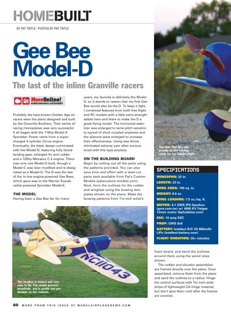
The <strong>Gee</strong><strong>Bee</strong> is honest and very<br />
easy to fly. The model grooves<br />
beautifully, and is gentle and predictable<br />
on the controls.<br />
years, my favorite is definitely the <strong>Model</strong>-<br />
D, so it stands to reason that my first <strong>Gee</strong><br />
<strong>Bee</strong> would also be the D. To keep it light,<br />
I combined features from both free flight<br />
and RC models with a little extra strength<br />
added here and there to make the D a<br />
great flying model. The horizontal stabilizer<br />
was enlarged to tame pitch sensitivity<br />
typical of short coupled airplanes and<br />
the ailerons were enlarged to increase<br />
their effectiveness. Using less throw<br />
eliminated adverse yaw often encountered<br />
with this type airplane.<br />
ON THE BUILDING BOARD<br />
Begin by cutting out all the parts using<br />
the patterns provided. You can also<br />
save time and effort with a laser-cut<br />
parts pack available from Pat’s Custom<br />
<strong>Model</strong>s (patscustom-models.com).<br />
Next, form the outlines for the rudder<br />
and wingtips using the bowing templates<br />
shown on the plans. Make the<br />
bowing patterns from 3 ⁄16-inch artist’s<br />
60 MORE FROM THIS ISSUE AT MODELAIRPLANENEWS.COM<br />
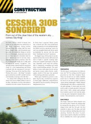
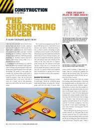
The little <strong>Gee</strong> <strong>Bee</strong> sits<br />
proudly on the runway,<br />
ready for her maiden flight.<br />
SPECIFICATIONS<br />
WINGSPAN: 32 in.<br />
LENGTH: 23 in.<br />
WING AREA: 165 sq. in.<br />
WEIGHT: 8.6 oz.<br />
WING LOADING: 7.5 oz./sq. ft.<br />
MOTOR: 4:1 GWS IPS Gearbox<br />
(gws.com.tw) w/ 4900 KV Feigao<br />
12mm motor (bphobbies.com)<br />
ESC: 10 amp ESC<br />
PROP: GWS 8x6<br />
BATTERY: Intellect R/C 2S 800mAh<br />
LiPo (intellect-battery.com)<br />
FLIGHT DURATION: 20+ minutes<br />
foam board, and bend the outlines<br />
around them using the wood sizes<br />
shown.<br />
The rudder and elevator assemblies<br />
are framed directly over the plans. Once<br />
assembled, remove them from the plans<br />
and sand the outlines to a radius. Hinge<br />
the control surfaces with 5 ⁄32-inch-wide<br />
strips of lightweight CA hinge material,<br />
but don’t glue them until after the frames<br />
are covered.
WING ASSEMBLY<br />
Construction begins with building up the<br />
spar assemblies using the landing gear<br />
mounts and the drawing details provided.<br />
Pin the spar assemblies over the<br />
plan at the center section. Glue ribs A1<br />
and the bolt plate A-4 in place, followed<br />
by the leading and trailing edges, and<br />
the balsa front servo rail. When dry,<br />
remove the pins from the assembly, rock<br />
it up onto the left panel and pin the<br />
spars to the plan. Fit and glue the ribs in<br />
place, followed by the leading and trailing<br />
edges. Fit and glue the tip bow in<br />
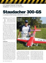
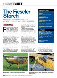
The horizontal stabilizer is built directly over<br />
the plans, sanded to shape and the hinges are<br />
then installed.<br />
place centered on the leading edge.<br />
Build the aileron in place on the wing<br />
assembly. Finally, glue the landing gear<br />
mount assembly and the balsa rigging<br />
blocks in place.<br />
When dry, remove the pins from the<br />
left panel and rock it over onto the right<br />
wing plan. Block up the left panel to<br />
prevent breaking the spars during<br />
assembly and build the other wing<br />
panel. With both panels complete,<br />
remove the wing assembly from the<br />
board and sand it to shape. Cut the<br />
ailerons from the wing assembly and<br />
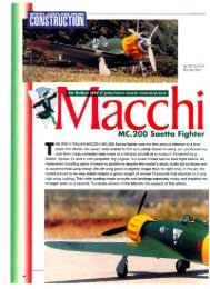
The two fuselage side frames are built directly<br />
over the plans.<br />
sand them to final shape. Make and<br />
install the 5 ⁄32-inch-wide CA hinges, but<br />
don’t glue until after covering.<br />
Fit the aluminum torque tubes into the<br />
wing and glue them in place. Make the<br />
bend on the outboard ends of the 0.056inch<br />
steel wire aileron torque rods and<br />
insert it into the tubes. Now make the<br />
bends on the inboard ends. Construct the<br />
aileron control links using the detail<br />
drawings and glue them to the torque<br />
rods with 5-minute epoxy. Fit the aft<br />
aileron servo mount beam into the wing<br />
using the servo to maintain proper spac-<br />
With the side frames glued to the firewall and<br />
wing-bolt plate, the remaining formers are<br />
glued in place.<br />
SEPTEMBER 2009 61
HOMEBUILT<br />
f<br />
To order the full-size plan, visit RCStore.com.<br />
K0909A GEE BEE MODEL-D<br />
Designed by expert model designer and builder Pat Tritle, this lightweight electric-powered,<br />
sport-scale <strong>Gee</strong> <strong>Bee</strong> <strong>Model</strong>-D is intended for intermediate to expert pilots. The model uses traditional<br />
balsa and plywood construction and a laser-cut short kit is available from the author.<br />
WS: 32 in.; L: 23 in.; Radio: 4-channel; Power: 10A geared motor w/ 8x6 prop; LD: 2;<br />
2 sheets: $21.95.<br />
ing. Bend the pushrods to shape, fit the<br />
ailerons back in place and adjust the<br />
pushrods as needed.<br />
THE FUSELAGE<br />
Build the fuselage side frames directly<br />
over the plans. Glue the pushrod exit slot<br />
pieces in place on the side frames so<br />
they fit flush with the outside of their<br />
respective frames. With the left side<br />
frame pinned to the framing plan, glue<br />
Former 2 in place. Be sure to orient the<br />
Former properly to accommodate built-in<br />
right motor thrust. Use a triangle or<br />
square to insure the former is perpendicular<br />
to the frame. Glue B2 in place,<br />
again using a square to insure proper<br />
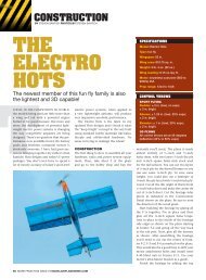
The motor mount assembly is assembled and<br />
then glued to the firewall. The right thrust is built<br />
into the mount gussets to insure its accuracy.<br />
alignment, then glue the right side frame<br />
to formers 2 and B2. Glue the stiffener in<br />
place on Former 1 then align and glue<br />
formers 1, 3, 3A, and 4 in place.<br />
Remove the frame assembly from the<br />
board and sand a bevel into the insides<br />
of the tail posts. Crack the longerons at<br />
former 4 and pull the tail together and<br />
glue. Glue formers 4A, 5, 5A, 6, and 6A in<br />
place, followed by the top stringers and<br />
the bottom centerline stringer aft of former<br />
4A. Build up the motor mount<br />
assembly and glue it in place on former<br />
2, followed by the balsa rigging block at<br />
former 3.<br />
Fit the wing into the saddle and drill<br />
the hole in the leading edge for the hold-<br />
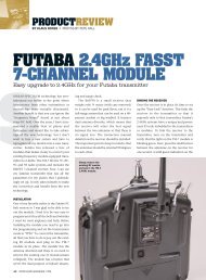
The wing panels are assembled directly over<br />
the plan. The “egg crate”-style construction<br />
insures a good fit and ease of assembly.<br />
62 MORE FROM THIS ISSUE AT MODELAIRPLANENEWS.COM<br />
down dowel. Glue the dowel in place<br />
then drill the hole in B2 and tap the hole<br />
for an 8-32 wing-hold-down bolt. With<br />
the wing bolted to the fuselage, fit and<br />
glue the center section formers and<br />
stringers in place followed by the<br />
remaining front fuselage stringers.<br />
Glue the servo rails in place to fit your<br />
servos and then run Sullivan no. 507<br />
pushrod tubes (sullivanproducts.com)<br />
into place. Support them at the front the<br />
center using the PRG wire guides shown<br />
on the plans.<br />
The motor mount details shown on the<br />
plans are for the Fiegao brushless motor<br />
(bphobbies.com) using a 4:1 IPS drive.<br />
Set up the motor and ESC then test run<br />
to ensure proper motor rotation. Slip the<br />
drive onto the mount and secure with a<br />
small dab of silicone sealant. Build up<br />
the tail-fairing blocks and carve them to<br />
shape. Either balsa or blue foam can be<br />
used. The nose bowl is also done using<br />
blue foam.<br />
LANDING GEAR AND STRUTS<br />
Bend the landing gear struts from<br />
0.056-inch steel wire and solder the<br />
struts together as shown. Glue the parts<br />
for the wheel pants together and capture<br />
the landing gear inside the wheel<br />
pants halves. Don’t forget to put the<br />
wheels in place. Carve the pants to<br />
shape and sand smooth. Fit the lower<br />
section of rib R2B into the landing gear<br />
and tack glue in place with a drop or<br />
two of CA. Don’t glue the landing gear<br />
assembly into the wing until the model<br />
has been covered.<br />
Build up the wing struts and then drill<br />
the holes in the fuselage and wing as<br />
shown to fit the struts making final<br />
length adjustments as needed.<br />
The wheels are assembled into the pants, then<br />
the assembly is carved and sanded to final<br />
shape.
COVERING AND FINISHING<br />
For smaller models like the <strong>Gee</strong> <strong>Bee</strong>, I<br />
use Nelson Litefilm, or Coverite’s<br />
Microlite (towerhobbies.com). However,<br />
since the number of colors is quite limited,<br />
some paint work is required. The<br />
Microlite can be masked and sprayed<br />
with enamels, or brushed with <strong>Model</strong><br />
Master Acryl or a water-based craft paint.<br />
Since some painting is required for the<br />
scale color scheme, Doculam material is<br />
also be a good covering choice. Markings<br />
and graphics for the original <strong>Gee</strong> <strong>Bee</strong> color<br />
scheme are available from Callie Graphics<br />
(callie-graphics.com/airplanes.php).<br />
FINAL ASSEMBLY<br />
Glue the rudder, aileron and elevator<br />
hinges in place using Pacer Formula 560<br />
Canopy Glue. Glue the landing gear into<br />
the wing, then bolt the wing onto the<br />
fuselage and use it as a reference for<br />
aligning and gluing the vertical and horizontal<br />
stabilizers and fairing blocks in<br />
place. Remove the wing, and install the<br />
0.025-inch steel rudder and elevator<br />
pushrods. Make Z-bends in each end,<br />
and do final control surface alignment<br />
while gluing the control horns in place.<br />
To install the Kevlar fishing line rigging,<br />
drill the holes in the bottom rigging block<br />
at the center section, wheel pants and the<br />
rigging blocks in both wings. Bend the<br />
wire hooks and glue them in place on<br />
Former 3. Now glue the rigging into the<br />
center section, then through the wheel<br />
pants and the rigging blocks on the wing,<br />
and up to the hooks. Slip the swivel over<br />
the hook and tie off the rigging using a<br />
small crimp. Check for the proper wing<br />
alignment and secure the rigging into the<br />
blocks with a drop of thin CA.<br />
Add the remaining details to finish up<br />
With all the framing and sanding done, the airframe<br />
is assembled and the radio and drive<br />
systems tested for proper operation. If problems<br />
are found, now would be a good time to<br />
get them corrected.<br />
The rudder uses a<br />
bowed outline and is<br />
built over the plans,<br />
sanded to shape and the<br />
hinges are then installed.<br />
BOWED OUTLINES<br />
Making up bowed outlines is a little out of the ordinary, but it isn’t<br />
difficult. Patterns are made from artist’s foam board or cardboard to form<br />
the bows. The wood is soaked in water for a few minutes to soften it up,<br />
then formed (wrapped) around the pattern and glued together.<br />
For best results, medium firm, straight-grained wood works best. The<br />
longer it soaks, the easier it will be to form. When pulling the wood<br />
around the form, tape one end to the form, then with firm, even<br />
pressure, draw the wood around. Then release the top layer and tape the<br />
inner layer at its end. Run a bead of glue along the inner stick and pull<br />
the outer back around and tape it in place.<br />
Here’s a trick to speed up the drying process. With the wood still taped<br />
to the form, place it in the microwave over for 10-12 seconds on High. If<br />
it comes out still a bit moist, let it cool, then put it back in for a second<br />
cycle. For more building information, go to modelairplanenews.com<br />
the model. Balance the model 1 1 ⁄2-inches<br />
back from the wing’s leading edge placing<br />
the battery and receiver to best<br />
accommodate the CG. Secure them in<br />
place with Velcro. Set up the control<br />
throws as shown to finish the model.<br />
IN THE AIR<br />
The <strong>Gee</strong> <strong>Bee</strong> can handle breezy conditions<br />
quite well, but it’s always a good<br />
idea to pick a calm day for test flights.<br />
Double check the control throws and<br />
direction and you’re ready to go.<br />
Line up the model on the runway and<br />
advance the throttle. As the model accelerates<br />
to flying speed it will hop on the<br />
mains a few times, then transition into a<br />
gentle climb at full power. Climb to altitude<br />
then trim for straight and level. The<br />
<strong>Model</strong>-D cruises nicely at about 2 ⁄3<br />
power; handling is gentle, yet positive<br />
throughout its speed range. While still at<br />
a safe altitude, check the stall. Mine<br />
slows down well and when it does break<br />
into the stall, it drops a wing. As soon as<br />
airspeed begins to increase, the model<br />
begins flying again. Due to prop torque,<br />
the <strong>Gee</strong> <strong>Bee</strong> turns a little better right then<br />
left. In a right turn, the model grooves<br />
beautifully. When turning left however,<br />
less aileron input is required as prop<br />
torque tends to roll the model into the<br />
turn more quickly. It’s not bad, but there<br />
is a noticeable difference.<br />
Landings are smooth and easy. Reduce<br />
power, set up your descent, line up on<br />
final and fly it down. Just before touch<br />
down, ease the nose up a bit and the D<br />
eases right into a 3-point attitude.<br />
Admittedly, I am a bit surprised that this<br />
little <strong>Gee</strong> <strong>Bee</strong> flies as well as it does. It<br />
acts more like a sport plane than a 1920sera<br />
Golden Age racer. Give the <strong>Gee</strong> <strong>Bee</strong><br />
<strong>Model</strong>-D a try, I’d bet you’ll like it. A<br />
SEPTEMBER 2009 63