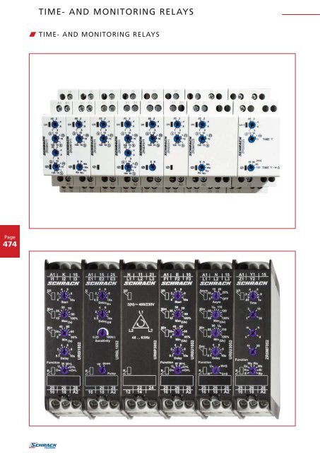
TIME- AND MONITORING RELAYS - Schrack
TIME- AND MONITORING RELAYS - Schrack
TIME- AND MONITORING RELAYS - Schrack

Create successful ePaper yourself
Turn your PDF publications into a flip-book with our unique Google optimized e-Paper software.
Page<br />
474<br />
<strong>TIME</strong>- <strong>AND</strong> <strong>MONITORING</strong> <strong>RELAYS</strong><br />
W <strong>TIME</strong>- <strong>AND</strong> <strong>MONITORING</strong> <strong>RELAYS</strong>
W MEASURING <strong>AND</strong> <strong>MONITORING</strong> <strong>RELAYS</strong><br />
W SERIES 5<br />
W SERIES 6<br />
<strong>TIME</strong>- <strong>AND</strong> <strong>MONITORING</strong> <strong>RELAYS</strong><br />
OPERATION DISPLAY<br />
LARGE <strong>TIME</strong> RANGE 50 ms – 100 h<br />
MANY FUNCTIONS<br />
45 mm CAP DIMENSION<br />
MULTI-VOLTAGE 12 or 24 V~/DC – 240 V~/DC<br />
INDUSTRIAL DESIGN<br />
WIDTH 22.5 mm<br />
MANY FUNCTIONS, E.G.:<br />
• Monitoring of phase sequence and phase failure<br />
• Detection of neutral wire break<br />
• Windows function<br />
• 16.6 – 400 Hz<br />
• Thermal resistor relay<br />
• Delayed contacts possible<br />
• Time range of timer relay: 1 s to 30 days<br />
Page<br />
475
Page<br />
476<br />
<strong>TIME</strong> <strong>RELAYS</strong><br />
w <strong>TIME</strong> RELAY ZR5E0011<br />
w TECHNICAL DATA<br />
1. Functions<br />
The function has to be set before connecting the relay to the<br />
supply voltage.<br />
E ON delay<br />
2. Time ranges<br />
Time range Adjustment range<br />
1 s 50 ms 1 s<br />
10 s 500 ms 10 s<br />
1 min 3 s 1 min<br />
10 min 30 s 10 min<br />
1 h 3 min 1 h<br />
10 h 30 min 10 h<br />
100 h 5 h 100 h<br />
w SCHRACK-INFO<br />
Wide input voltage range<br />
1 change over contact<br />
Width 17,5 mm<br />
Installation design<br />
3. Indicators<br />
Green LED U/t ON: indication of supply voltage<br />
Green LED U/t flashes: indication of time period<br />
Yellow LED R ON/OFF: indication of relay outputs<br />
4. Mechanical design<br />
Self-extinguishing plastic housing, IP rating IP40<br />
Mounted on DIN-rail TS 35 according to EN 50022<br />
Mounting position: any<br />
Shockproof terminal connection according to VBG 4 (PZ1<br />
required), IP rating IP20<br />
Tightening torque: max. 1 Nm<br />
Terminal capacity:<br />
1 x 0.5 to 2.5 mm² with/without multicore cable end<br />
1 x 4 mm² without multicore cable end<br />
2 x 0.5 to 1.5 mm² with/without multicore cable end<br />
2 x 2.5 mm² flexible without multicore cable end<br />
5. Input circuit<br />
Supply voltage: Terminals A1(+)-A2<br />
Types ZR5..24-240 V AC/DC: 24 to 240 V AC/DC<br />
Tolerance: 24 V-15% to 240 V+10%<br />
Rated consumption: 4 VA (1.5 W)<br />
Rated frequency: AC 48 to 63 Hz<br />
Duty cycle: 100%<br />
Reset time: 100 ms<br />
Residual ripple for DC: 10%<br />
Drop-out voltage: >30% of minimum rated supply<br />
voltage<br />
Overvoltage category: III (according to IEC 60664-1)<br />
Rated surge voltage: 4 kV<br />
6. Output circuit<br />
1 potential free change over contact<br />
Rated voltage: 250 V AC<br />
Switching capacity: 2000 VA (8 A / 250V)<br />
Fusing: 8 A fast acting<br />
Mechanical life: 20 x 106 operations<br />
Electrical life: 2 x 10⁵ operations<br />
at 1000 VA resistive load<br />
Switching frequency: max. 60/min at 100 VA resistive load<br />
max. 6/min at 1000 VA resistive load<br />
(according to IEC 947-5-1)<br />
Overvoltage category: III. (according to IEC 60664-1)<br />
Rated surge voltage:<br />
7. Control input<br />
4 kV<br />
Input not potential free: Terminals A1-B1<br />
Loadable: yes<br />
Max. line length: 10m<br />
Trigger level (sensitivity): automatic adaption to supply<br />
voltage<br />
Min. control pulse length: DC 50 ms / AC 100 ms<br />
8. Accuracy<br />
Base accuracy: ±1% of maximum scale value<br />
Adjustment accuracy:
w FUNCTIONS w CONNECTIONS<br />
without control input<br />
ON delay (E)<br />
When the supply voltage U is applied, the set interval t begins (green LED<br />
U/t flashes). After the interval t has expired (green LED U/t illuminated)<br />
the output relay R switches into on-position (yellow LED illuminated). This<br />
status remains until the supply voltage is interrupted. If the supply voltage is<br />
interrupted before the expiry of the interval t, the interval already expired<br />
is erased and is restarted when the supply voltage is next applied.<br />
w WEIGHT<br />
Single packing: 72 g<br />
Package 10 pcs: 670 g per Package<br />
W ARTICLE NUMBER<br />
DESCRIPTION<br />
Single function timerelay E (ON delay),<br />
ORDER NO.<br />
24-240VAC, 1 change over, 8A/250V ZR5E0011<br />
Order no. blue: on stock, usually ready for delivery on the day of order!<br />
w DIMENSIONS<br />
<strong>TIME</strong> <strong>RELAYS</strong><br />
DESCRIPTION EAN CODE AVAILABLE ORDER NO.<br />
Single function time relay E (ON delay), 24-240VAC, 1 change over, 8A/250V 9004840459029 ZR5E0011<br />
I KNOW WHERE TO FIND IT!<br />
THE SCHRACK TECHNIK WEB SHOP WITH NAVIGATOR<br />
WWW.SCHRACK.COM<br />
• Finding product information made easy<br />
• Buying products around the clock<br />
• Quick access customer service<br />
Page<br />
477
Page<br />
478<br />
<strong>TIME</strong> <strong>RELAYS</strong><br />
w <strong>TIME</strong> RELAY ZR5R0011<br />
w TECHNICAL DATA<br />
1. Functions<br />
The function has to be set before connecting the relay to the<br />
supply voltage.<br />
R OFF delay<br />
2. Time ranges<br />
Time range Adjustment range<br />
1 s 50 ms 1 s<br />
10 s 500 ms 10 s<br />
1 min 3 s 1 min<br />
10 min 30 s 10 min<br />
1 h 3 min 1 h<br />
10 h 30 min 10 h<br />
100 h 5 h 100 h<br />
w SCHRACK-INFO<br />
Wide input voltage range<br />
1 change over contact<br />
Width 17,5 mm<br />
Installation design<br />
3. Indicators<br />
Green LED U/t ON: indication of supply voltage<br />
Green LED U/t flashes: indication of time period<br />
Yellow LED R ON/OFF: indication of relay outputs<br />
4. Mechanical design<br />
Self-extinguishing plastic housing, IP rating IP40<br />
Mounted on DIN-rail TS 35 according to EN 50022<br />
Mounting position: any<br />
Shockproof terminal connection according to VBG 4 (PZ1<br />
required), IP rating IP20<br />
Tightening torque: max. 1 Nm<br />
Terminal capacity:<br />
1 x 0.5 to 2.5 mm² with/without multicore cable end<br />
1 x 4 mm² without multicore cable end<br />
2 x 0.5 to 1.5 mm² with/without multicore cable end<br />
2 x 2.5 mm² flexible without multicore cable end<br />
5. Input circuit<br />
Supply voltage: Terminals A1(+)-A2<br />
Types ZR5..24-240 V AC/DC: 24 to 240 V AC/DC<br />
Tolerance: 24 V-15% to 240 V+10%<br />
Rated consumption: 4 VA (1.5 W)<br />
Rated frequency: AC 48 to 63 Hz<br />
Duty cycle: 100%<br />
Reset time: 100 ms<br />
Residual ripple for DC: 10%<br />
Drop-out voltage: >30% of minimum rated supply<br />
voltage<br />
Overvoltage category: III (according to IEC 60664-1)<br />
Rated surge voltage: 4 kV<br />
6. Output circuit<br />
1 potential free change over contact<br />
Rated voltage: 250 V AC<br />
Switching capacity: 2000 VA (8 A / 250V)<br />
Fusing: 8 A fast acting<br />
Mechanical life: 20 x 106 operations<br />
Electrical life: 2 x 10⁵ operations<br />
at 1000 VA resistive load<br />
Switching frequency: max. 60/min at 100 VA resistive load<br />
max. 6/min at 1000 VA resistive load<br />
(according to IEC 947-5-1)<br />
Overvoltage category: III. (according to IEC 60664-1)<br />
Rated surge voltage:<br />
7. Control input<br />
4 kV<br />
Input not potential free: Terminals A1-B1<br />
Loadable: yes<br />
Max. line length: 10m<br />
Trigger level (sensitivity): automatic adaption to supply<br />
voltage<br />
Min. control pulse length: DC 50 ms / AC 100 ms<br />
8. Accuracy<br />
Base accuracy: ±1% of maximum scale value<br />
Adjustment accuracy:
w FUNCTIONS w CONNECTIONS<br />
OFF delay (R)<br />
with control input<br />
The supply voltage U must be constantly applied to the device (green<br />
LED U/t illuminated). When the control contact S is closed, the output<br />
relay R switches into on-position (yellow LED illuminated). If the<br />
control contact is opened, the set interval t begins (green LED<br />
flashes). After the interval t has expired (green LED U/t illuminated) the<br />
output relay switches into off-position (yellow LED not illuminated). If<br />
the control contact is closed again before the interval t has expired,<br />
the interval already expired is erased and is restarted.<br />
w WEIGHT<br />
Single packing: 72 g<br />
Package 10 pcs: 670 g per Package<br />
W ARTICLE NUMBER<br />
DESCRIPTION<br />
Single function timerelay R (OFF delay),<br />
ORDER NO.<br />
24-240VAC, 1 change over, 8A/250V ZR5R0011<br />
Order no. blue: on stock, usually ready for delivery on the day of order!<br />
w DIMENSIONS<br />
<strong>TIME</strong> <strong>RELAYS</strong><br />
DESCRIPTION EAN CODE AVAILABLE ORDER NO.<br />
Single function time relay R (OFF delay), 24-240VAC, 1 change over, 8A/250V 9004840459050 ZR5R0011<br />
I KNOW WHERE TO FIND IT!<br />
WITH THE SCHRACK TECHNIK LiVE-PHONE APP<br />
• Access technical product information at any time and from everywhere<br />
• See availability and price immediately<br />
• Order desired products easily<br />
Page<br />
479
Page<br />
480<br />
<strong>TIME</strong> <strong>RELAYS</strong><br />
w <strong>TIME</strong> RELAY ZR5ER011<br />
w TECHNICAL DATA<br />
1. Functions<br />
The function has to be set before connecting the relay to the<br />
supply voltage.<br />
E ON delay<br />
R OFF delay<br />
2. Time ranges<br />
Time range Adjustment range<br />
1 s 50 ms 1 s<br />
10 s 500 ms 10 s<br />
1 min 3 s 1 min<br />
10 min 30 s 10 min<br />
1 h 3 min 1 h<br />
10 h 30 min 10 h<br />
100 h 5 h 100 h<br />
w SCHRACK-INFO<br />
2 functions<br />
7 time ranges<br />
Wide input voltage range<br />
1 change over contact<br />
Width 17,5 mm<br />
Installation design<br />
3. Indicators<br />
Green LED U/t ON: indication of supply voltage<br />
Green LED U/t flashes: indication of time period<br />
Yellow LED R ON/OFF: indication of relay outputs<br />
4. Mechanical design<br />
Self-extinguishing plastic housing, IP rating IP40<br />
Mounted on DIN-rail TS 35 according to EN 50022<br />
Mounting position: any<br />
Shockproof terminal connection according to VBG 4 (PZ1<br />
required), IP rating IP20<br />
Tightening torque: max. 1 Nm<br />
Terminal capacity:<br />
1 x 0.5 to 2.5 mm² with/without multicore cable end<br />
1 x 4 mm² without multicore cable end<br />
2 x 0.5 to 1.5 mm² with/without multicore cable end<br />
2 x 2.5 mm² flexible without multicore cable end<br />
5. Input circuit<br />
Supply voltage: Terminals % A1(+)-A2 %<br />
Types ZR5..24-240 V AC/DC: 24 to 240 V AC/DC<br />
Tolerance: 24 V-15% to 240 V+10%<br />
Rated consumption: 4 VA (1.5 W)<br />
Rated frequency: AC 48 to 63 Hz<br />
Duty cycle: 100%<br />
Reset time: 100 ms<br />
Residual ripple for DC: 10%<br />
Drop-out voltage: >30% of minimum rated supply<br />
voltage<br />
Overvoltage category: III (according to IEC 60664-1)<br />
Rated surge voltage: 4 kV<br />
6. Output circuit<br />
1 potential free change over contact<br />
Rated voltage: 250 V AC<br />
Switching capacity: 2000 VA (8 A / 250V)<br />
Fusing: 8 A fast acting<br />
Mechanical life: 20 x 106 operations<br />
Electrical life: 2 x 10⁵ operations<br />
at 1000 VA resistive load<br />
Switching frequency: max. 60/min at 100 VA resistive load<br />
max. 6/min at 1000 VA resistive load<br />
(according to IEC 947-5-1)<br />
Overvoltage category: III. (according to IEC 60664-1)<br />
Rated surge voltage:<br />
7. Control input<br />
4 kV<br />
Input not potential free: Terminals A1-B1<br />
Loadable: yes<br />
Max. line length: 10m<br />
Trigger level (sensitivity): automatic adaption to supply<br />
voltage<br />
Min. control pulse length: DC 50 ms / AC 100 ms<br />
8. Accuracy<br />
Base accuracy: ±1% of maximum scale value<br />
Adjustment accuracy:
ON delay (E)<br />
When the supply voltage U is applied, the set interval t begins (green LED<br />
U/t flashes). After the interval t has expired (green LED U/t illuminated)<br />
the output relay R switches into on-position (yellow LED illuminated). This<br />
status remains until the supply voltage is interrupted. If the supply voltage is<br />
interrupted before the expiry of the interval t, the interval already expired<br />
is erased and is restarted when the supply voltage is next applied.<br />
Single packing: 72 g<br />
Package 10 pcs: 670 g per Package<br />
Order no. blue: on stock, usually ready for delivery on the day of order!<br />
<strong>TIME</strong> <strong>RELAYS</strong><br />
w FUNCTIONS w CONNECTIONS<br />
with control input without control input<br />
OFF delay (R)<br />
The supply voltage U must be constantly applied to the device (green<br />
LED U/t illuminated). When the control contact S is closed, the output<br />
relay R switches into on-position (yellow LED illuminated). If the<br />
control contact is opened, the set interval t begins (green LED<br />
flashes). After the interval t has expired (green LED U/t illuminated) the<br />
output relay switches into off-position (yellow LED not illuminated). If<br />
the control contact is closed again before the interval t has expired,<br />
the interval already expired is erased and is restarted.<br />
w DIMENSIONS<br />
w WEIGHT W ARTICLE NUMBER<br />
DESCRIPTION<br />
Double function timerelay E (ON delay) + R (OFF delay),<br />
ORDER NO.<br />
24-240VAC, 1 change over, 8A/250V ZR5ER011<br />
DESCRIPTION EAN CODE AVAILABLE ORDER NO.<br />
Double function time relay E (ON delay) + R (OFF delay), 24-240VAC, 1 change over, 8A/250V 9004840459036 ZR5ER011<br />
I KNOW WHERE TO FIND IT!<br />
THE SCHRACK TECHNIK WEB SHOP WITH NAVIGATOR<br />
WWW.SCHRACK.COM<br />
• Finding product information made easy<br />
• Buying products around the clock<br />
• Quick access customer service<br />
Page<br />
481
Page<br />
482<br />
<strong>TIME</strong> <strong>RELAYS</strong><br />
w MULTIFUNCTION <strong>TIME</strong> RELAY ZR5MF011<br />
w TECHNICAL DATA<br />
1. Functions<br />
The functions has to be set before connecting the relay to<br />
the supply voltage.<br />
E ON delay<br />
R OFF delay<br />
Ws Single shot leading edge with control input<br />
Wa Single shot trailing edge with control input<br />
Es ON delay with control input<br />
Wu Single shot leading edge voltage controlled<br />
Bp Flasher pause first<br />
2. Time ranges<br />
Time range Adjustment range<br />
1 s 50 ms 1 s<br />
10 s 500 ms 10 s<br />
1 min 3 s 1 min<br />
10 min 30 s 10 min<br />
1 h 3 min 1 h<br />
10 h 30 min 10 h<br />
100 h<br />
3. Indicators<br />
5 h 100 h<br />
Green LED U/t ON: indication of supply voltage<br />
Green LED U/t flashes: indication of time period<br />
Yellow LED R ON/OFF:<br />
4. Mechanical design<br />
indication of relay output<br />
Self-extinguishing plastic housing, IP rating IP40<br />
Mounted on DIN-rail TS 35 according to EN 50022<br />
Mounting position: any<br />
Shockproof terminal connection according to VBG 4 (PZ1 required),<br />
IP rating IP20<br />
Tightening torque:<br />
Terminal capacity:<br />
max. 1 Nm<br />
1 x 0.5 to 2.5 mm² with/without multicore cable end<br />
1 x 4 mm² without multicore cable end<br />
2 x 0.5 to 1.5 mm² with/without multicore cable end<br />
2 x 2.5 mm² flexible without multicore cable end<br />
5. Input circuit<br />
Supply voltage: terminals A1(+)-A2<br />
Type ZR5MF025 12 to 240 V AC/DC<br />
Tolerance: 12 V-10% to 240 V+10%<br />
Rated consumption: 6 4 VA (2 (1.5 W) W)<br />
w SCHRACK-INFO<br />
• Timers multifunctional<br />
• Up to 7 functions<br />
• 7 time ranges<br />
• Wide input voltage range<br />
• 1 change over contact<br />
• Width 17,5 mm<br />
• Installation design<br />
Rated frequency: AC 48 to 63 Hz<br />
Duty cycle: 100%<br />
Reset time: 100 ms<br />
Residual ripple for DC: 10%<br />
Drop-out voltage: >30% of minimum rated supply<br />
voltage<br />
Overvoltage category: III (according to IEC 60664-1)<br />
Rated surge voltage:<br />
6. Output circuit<br />
4kV<br />
1 2 potential free change over contacts<br />
Rated voltage: 250 V AC<br />
Switching capacity: 2000 VA (8 A / 250 V)<br />
Fusing: 8 A fast acting<br />
Mechanical life: 20 x 106 operations<br />
Electrical life: 2 x 10⁵ operations<br />
at 1000 VA resistive load<br />
Switching frequency: max. 60/min at 100VA resistive load<br />
max. 6/min at 1000VA resistive load<br />
(according to IEC 947-5-1)<br />
Overvoltage category: III. (according to IEC 60664-1)<br />
Rated surge voltage:<br />
7. Control input<br />
4kV<br />
Input not potential free: terminals A1-B1<br />
Loadable: yes<br />
Max. line length: 10m<br />
Trigger level (sensitivity): automatic adaption to supply voltage<br />
Min. control pulse length: DC 50 ms / AC 100 ms<br />
8. Accuracy<br />
Base accuracy: ±1% of maximum scale value<br />
Adjustment accuracy:
w FUNCTIONS<br />
ON delay (E)<br />
When the supply voltage U is applied, the set interval t begins (green<br />
LED U/t flashes). After the interval t has expired (green LED U/t<br />
illuminated) the output relay R switches into on-position (yellow LED<br />
illuminated). This status remains until the supply voltage is interrupted.<br />
If the supply voltage is interrupted before the expiry of the interval t,<br />
the interval already expired is erased and is restarted when the supply<br />
voltage is next applied.<br />
OFF delay (R)<br />
The supply voltage U must be constantly applied to the device (green<br />
LED U/t illuminated). When the control contact S is closed, the output<br />
relay R switches into on-position (yellow LED illuminated). If the control<br />
contact is opened, the set interval t begins (green LED U/t flashes).<br />
After the interval t has expired (green LED U/t illuminated) the output<br />
relay switches into off-position (yellow LED not illuminated). If the control<br />
contact is closed again before the interval t has expired, the interval<br />
already expired is erased and is restarted.<br />
Single shot leading edge with control input (Ws)<br />
The supply voltage U must be constantly applied to the device (green<br />
LED U/t illuminated). When the control contact S is closed, the output<br />
relay R switches into on-position (green LED U/t illuminated) and the<br />
set interval t begins (green LED U/t flashes). After the interval t has<br />
expired (green LED U/t illuminated) the output relay switches into<br />
off-position (yellow LED not illuminated). During the interval, the control<br />
contact can be operated any number of times. A further cycle can only<br />
be started when the cycle run has been completed.<br />
Single shot trailling edge with control input (Wa)<br />
The supply voltage U must be constantly applied to the device (green<br />
LED U/t illuminated). Closing the control contact S has no influence on<br />
the condition of the output R. When the control contact is opened, the<br />
output relay switches into on-position (yellow LED illuminated) and the<br />
set interval t begins (green LED U/t flashes). After the interval t has expired<br />
(green LED U/t illuminated), the ouput relay switches into off-position (yellow<br />
LED not illuminated). During the interval, the control contact can be<br />
operated any number of times. A further cycle can only be started when<br />
the cycle run has been completed.<br />
ON delay with control input (Es)<br />
The supply voltage U must be constantly applied to the device (green<br />
LED U/t illuminated). When teh control contact S is closed, the set<br />
interval t begins (green LED U/t flashes). After the interval t has expired<br />
(green LED U/t illuminated) the output relay R switches into on-position<br />
(yellow LED illuminated). This status remains until the control<br />
contact is opened again. If the control contact is opened before the<br />
interval t has expired , the interval already expired is erased and is<br />
restarted with the next cycle.<br />
<strong>TIME</strong> <strong>RELAYS</strong><br />
Single shot leading edge voltage controlled (Wu)<br />
When the supply voltage U is applied, the output relay R switches<br />
into on-position (yellow LED illuminated) and the set interval t begins<br />
(green LED U/t flashes). After the interval t has expired (green LED U/t<br />
illuminated) the output relay switches into off-position (yellow LED not<br />
illuminated). This status remains until the supply voltage is interrupted.<br />
If the supply voltage is interruted before the interval t has expired, the<br />
output relay switches into off-position. The interval already is erased<br />
and is restarted when the supply voltage is next applied.<br />
Flasher pause first (Bp)<br />
When the supply voltage U is applied, the set interval t begins (green<br />
LED U/t flashes). After the interval t has expired, the output relay R<br />
switches into on-position (yellow LED illuminated) and the set interval t<br />
begins again. After the interval t has expired, the output relay switches<br />
into off-position (yellow LED not illuminated).<br />
The output relay is triggered at a ratio of 1:1 until the supply voltage is<br />
interrupted.<br />
w CONNECTIONS<br />
with control input without control input<br />
w DIMENSIONS<br />
w WEIGHT<br />
Single packing: 72 g<br />
Package 10 pcs: 670 g per Package<br />
W ARTICLE NUMBER<br />
DESCRIPTION<br />
Multifunction timerelay E, R, Ws, Wa, Es, Wu, Bp,<br />
ORDER NO.<br />
12-240VAC, 1 change over, 8A/250V ZR5MF011<br />
DESCRIPTION EAN CODE AVAILABLE ORDER NO.<br />
Multifunction time relay E, R, Ws, Wa, Es, Wu, Bp, 12-240VAC, 1 change over, 8A/250V 9004840459043 ZR5MF011<br />
Order no. blue: on stock, usually ready for delivery on the day of order!<br />
Page<br />
483
Page<br />
484<br />
<strong>TIME</strong> <strong>RELAYS</strong><br />
w MULTIFUNCTION <strong>TIME</strong> RELAY ZR5MF025<br />
w TECHNICAL DATA<br />
w SCHRACK-INFO<br />
• Timers multifunctional<br />
• Up to 7 functions<br />
• 7 time ranges<br />
• Wide input voltage range<br />
• 2 change-over contacts<br />
• Width 35 mm<br />
• Installation design<br />
1. Functions<br />
The functions has to be set before connecting the relay to<br />
the supply voltage.<br />
E ON delay<br />
R OFF delay<br />
Ws Single shot leading edge with control input<br />
Wa Single shot trailing edge with control input<br />
Es ON delay with control input<br />
Wu Single shot leading edge voltage controlled<br />
Bp Flasher pause first<br />
2. Time ranges<br />
Time range Adjustment range<br />
1 s 50 ms 1 s<br />
10 s 500 ms 10 s<br />
1 min 3 s 1 min<br />
10 min 30 s 10 min<br />
1 h 3 min 1 h<br />
10 h 30 min 10 h<br />
100 h<br />
3. Indicators<br />
5 h 100 h<br />
Green LED U/t ON: indication of supply voltage<br />
Green LED U/t flashes: indication of time period<br />
Yellow LED R ON/OFF:<br />
4. Mechanical design<br />
indication of relay output<br />
Self-extinguishing plastic housing, IP rating IP40<br />
Mounted on DIN-rail TS 35 according to EN 50022<br />
Mounting position: any<br />
Shockproof terminal connection according to VBG 4 (PZ1 required),<br />
IP rating IP20<br />
Tightening torque:<br />
Terminal capacity:<br />
max. 1 Nm<br />
1 x 0.5 to 2.5 mm² with/without multicore cable end<br />
1 x 4 mm² without multicore cable end<br />
2 x 0.5 to 1.5 mm² with/without multicore cable end<br />
2 x 2.5 mm² flexible without multicore cable end<br />
5. Input circuit<br />
Supply voltage: terminals A1(+)-A2<br />
Type ZR5MF025 12 to 240 V AC/DC<br />
Tolerance: 12 V-10% to 240 V+10%<br />
Rated consumption: 6 VA (2 W)<br />
Rated frequency: AC 48 to 63 Hz<br />
Duty cycle: 100%<br />
Reset time: 100 ms<br />
Residual ripple for DC: 10%<br />
Drop-out voltage: >30% of minimum rated supply<br />
voltage<br />
Overvoltage category: III (according to IEC 60664-1)<br />
Rated surge voltage:<br />
6. Output circuit<br />
4kV<br />
2 potential free change over contacts<br />
Rated voltage: 250 V AC<br />
Switching capacity: 2000 VA (8 A / 250 V)<br />
Fusing: 8 A fast acting<br />
Mechanical life: 20 x 106 operations<br />
Electrical life: 2 x 10⁵ operations<br />
at 1000 VA resistive load<br />
Switching frequency: max. 60/min at 100VA resistive load<br />
max. 6/min at 1000VA resistive load<br />
(according to IEC 947-5-1)<br />
Overvoltage category: III. (according to IEC 60664-1)<br />
Rated surge voltage:<br />
7. Control input<br />
4kV<br />
Input not potential free: terminals A1-B1<br />
Loadable: yes<br />
Max. line length: 10m<br />
Trigger level (sensitivity): automatic adaption to supply voltage<br />
Min. control pulse length: DC 50 ms / AC 100 ms<br />
8. Accuracy<br />
Base accuracy: ±1% of maximum scale value<br />
Adjustment accuracy:
w FUNCTIONS<br />
ON delay (E)<br />
When the supply voltage U is applied, the set interval t begins (green<br />
LED U/t flashes). After the interval t has expired (green LED U/t<br />
illuminated) the output relay R switches into on-position (yellow LED<br />
illuminated). This status remains until the supply voltage is interrupted.<br />
If the supply voltage is interrupted before the expiry of the interval t,<br />
the interval already expired is erased and is restarted when the supply<br />
voltage is next applied.<br />
OFF delay (R)<br />
The supply voltage U must be constantly applied to the device (green<br />
LED U/t illuminated). When the control contact S is closed, the output<br />
relay R switches into on-position (yellow LED illuminated). If the control<br />
contact is opened, the set interval t begins (green LED U/t flashes).<br />
After the interval t has expired (green LED U/t illuminated) the output<br />
relay switches into off-position (yellow LED not illuminated). If the control<br />
contact is closed again before the interval t has expired, the interval<br />
already expired is erased and is restarted.<br />
Single shot leading edge with control input (Ws)<br />
The supply voltage U must be constantly applied to the device (green<br />
LED U/t illuminated). When the control contact S is closed, the output<br />
relay R switches into on-position (green LED U/t illuminated) and the<br />
set interval t begins (green LED U/t flashes). After the interval t has<br />
expired (green LED U/t illuminated) the output relay switches into<br />
off-position (yellow LED not illuminated). During the interval, the control<br />
contact can be operated any number of times. A further cycle can only<br />
be started when the cycle run has been completed.<br />
Single shot trailling edge with control input (Wa)<br />
The supply voltage U must be constantly applied to the device (green<br />
LED U/t illuminated). Closing the control contact S has no influence on<br />
the condition of the output R. When the control contact is opened, the<br />
output relay switches into on-position (yellow LED illuminated) and the<br />
set interval t begins (green LED U/t flashes). After the interval t has expired<br />
(green LED U/t illuminated), the ouput relay switches into off-position (yellow<br />
LED not illuminated). During the interval, the control contact can be<br />
operated any number of times. A further cycle can only be started when<br />
the cycle run has been completed.<br />
ON delay with control input (Es)<br />
The supply voltage U must be constantly applied to the device (green<br />
LED U/t illuminated). When teh control contact S is closed, the set<br />
interval t begins (green LED U/t flashes). After the interval t has expired<br />
(green LED U/t illuminated) the output relay R switches into on-position<br />
(yellow LED illuminated). This status remains until the control<br />
contact is opened again. If the control contact is opened before the<br />
interval t has expired , the interval already expired is erased and is<br />
restarted with the next cycle.<br />
Order no. blue: on stock, usually ready for delivery on the day of order!<br />
<strong>TIME</strong> <strong>RELAYS</strong><br />
Single shot leading edge voltage controlled (Wu)<br />
When the supply voltage U is applied, the output relay R switches<br />
into on-position (yellow LED illuminated) and the set interval t begins<br />
(green LED U/t flashes). After the interval t has expired (green LED U/t<br />
illuminated) the output relay switches into off-position (yellow LED not<br />
illuminated). This status remains until the supply voltage is interrupted.<br />
If the supply voltage is interruted before the interval t has expired, the<br />
output relay switches into off-position. The interval already is erased<br />
and is restarted when the supply voltage is next applied.<br />
Flasher pause first (Bp)<br />
When the supply voltage U is applied, the set interval t begins (green<br />
LED U/t flashes). After the interval t has expired, the output relay R<br />
switches into on-position (yellow LED illuminated) and the set interval t<br />
begins again. After the interval t has expired, the output relay switches<br />
into off-position (yellow LED not illuminated).<br />
The output relay is triggered at a ratio of 1:1 until the supply voltage is<br />
interrupted.<br />
w CONNECTIONS<br />
with control input without control input<br />
w DIMENSIONS<br />
w WEIGHT<br />
Single packing: 106g<br />
W ARTICLE NUMBER<br />
DESCRIPTION ORDER NO.<br />
Timerelay, multifunction, 12-240VAC, 2 change over, 8A/250V ZR5MF025<br />
DESCRIPTION EAN CODE AVAILABLE ORDER NO.<br />
Multifunction time relay, 12-240VAC, 2 change over, 8A/250V 9004840507287 ZR5MF025<br />
Page<br />
485
Page<br />
486<br />
<strong>TIME</strong> <strong>RELAYS</strong><br />
w MULTIFUNCTION <strong>TIME</strong> RELAY ZR6MF052<br />
w TECHNICAL DATA<br />
1. Functions<br />
1 delayed contact (terminals 15-16-18) and<br />
1 instantaneous contact (terminals 25-26-28<br />
E11 ON delay<br />
R11 OFF delay with control contact<br />
Es11 ON delay with control contact<br />
Wu11 Single shot leading edge voltage controlled<br />
Ws11 Single shot leading edge with control contact<br />
Wa11 Single shot trailing edge with control contact<br />
Bi11 Flasher pulse first<br />
Bp11 Flasher pause first<br />
2 delayed contacts<br />
E20 ON delay<br />
R20 OFF delay with control contact<br />
Es20 ON delay with control contact<br />
Wu20 Single shot leading edge voltage controlled<br />
Ws20 Single shot leading edge with control contact<br />
Wa20 Single shot trailing edge with control contact<br />
Bi20 Flasher pulse first<br />
Bp20 Flasher pause first<br />
2. Time ranges<br />
Time range Adjustment range<br />
1s 50ms 1s<br />
3s 150ms 3s<br />
10s 500ms 10s<br />
30s 1500ms 30s<br />
1min 3s 1min<br />
3min 9s 3min<br />
10min 30s 10min<br />
30min 90s 30min<br />
1h 3min 1h<br />
3h 9min 3h<br />
10h 30min 10h<br />
30h 90min 30h<br />
1d 72min 1d<br />
3d 216min 3d<br />
10d 12h 10d<br />
30d 36h 30d<br />
• 16 functions<br />
• 16 time ranges<br />
• Connection of remote potentiometer possible<br />
• Zoom voltage 24 to 240V AC/DC<br />
• 2 change-over contacts<br />
• Width 22.5 mm<br />
• Industrial design<br />
3. Indicators<br />
Green LED ON: indication of supply voltage<br />
Green LED flashes: indication of time period<br />
Yellow LED ON/OFF: indication of relay output<br />
4. Mechanical design<br />
Self-extinguishing plastic housing, IP rating IP40<br />
Mounted on DIN-Rail TS 35 according to EN 60715<br />
Mounting position: any<br />
Shockproof terminal connection according to VBG 4<br />
(PZ1 required), IP rating IP20<br />
Tightening torque: max. 1Nm<br />
Terminal capacity:<br />
1 x 0.5 bis 2.5 mm² with/without multicore cable end<br />
1 x 4 mm² without multicore cable end<br />
2 x 0.5 bis 1.5 mm² with/without multicore cable end<br />
2 x 2.5 mm² flexible without multicore cable end<br />
5. Input circuit<br />
Supply voltage:<br />
24 to 240V AC/DC terminals A1-A2<br />
(galvanically separated)<br />
Tolerance:<br />
24 to 240V DC -20% to +25%<br />
24 to 240V AC -15% to +10%<br />
Rated frequency:<br />
24 to 240V AC 48 to 400Hz<br />
48 to 240V AC 16 to 48Hz<br />
Rated consumption: 4.5VA (1W)<br />
Duration of operation: 100%<br />
Reset time: 500ms<br />
Wave form for AC: Sinus<br />
Residual ripple for DC: 10%<br />
Drop-out voltage: >15% of the supply voltage<br />
Overvoltage category: III (in accordance with<br />
IEC 60661-1)<br />
Rated surge voltage: 4kV
6. Output circuit<br />
2 potential free change-over contacts<br />
Rated voltage: 250V AC<br />
Switching capacity (distance 5mm):<br />
1250VA (5A / 250V AC)<br />
Fusing: 5A fast acting<br />
Mechanical life: 20 x 10 6 operations<br />
Electrical Life: 2 x 10 5 operations at<br />
1000VA resistive load<br />
Switching frequency: max. 60/min at 100VA<br />
resistive load<br />
max. 6/min at 1000VA<br />
resistive load<br />
(in accordance with IEC 60947-5-1)<br />
Overvoltage category: III (in accordance with IEC 60664-1)<br />
Rated surge voltage: 4kV<br />
7. Control contact<br />
Activation: bridge Y1-Y2<br />
Potential free: yes, basic isolation against<br />
input and output circuit<br />
Loadable: no<br />
Control voltage: max. 5V<br />
Short circuit current: max. 1mA<br />
Line length: max. 10m<br />
Control pulse length: min. 50ms<br />
w FUNCTIONS<br />
The internal potentiometer is de-activated when a remote-potentio-meter<br />
is connected !The function has to be set before connecting<br />
the relay to the supply voltage.<br />
ON delay (E11)<br />
When the supply voltage U is applied, the instantaneous contact<br />
switches into on-position and the set interval t begins (green LED<br />
flashes). After the interval t has expired (green LED illuminated) the<br />
delayed contact switches into on-position (yellow LED illuminated).<br />
This status remains until the supply voltage is interrupted. If the<br />
supply voltage is interrupted before the expiry of the interval t, the<br />
interval already expired is erased and is restarted when the supply<br />
voltage is next applied.<br />
U<br />
LED U<br />
R 15-16-18<br />
R 25-26-28<br />
t
Page<br />
488<br />
<strong>TIME</strong> <strong>RELAYS</strong><br />
ON delay with control contact (Es11)<br />
The supply voltage U must be constantly applied to the device<br />
(green LED illuminated). When the control contact Y1-Y2 is<br />
closed, the instantaneous contact switches into on-position and<br />
the set interval t begins (green LED flashes). After the interval t<br />
has expired (green LED illuminated) the delayed contact switches<br />
into on-position (yellow LED illuminated). This status remains until<br />
the control contact is opened again .If the control contact is<br />
opened before the interval t has expired, the interval already<br />
expired is erased and is restarted with the next cycle.<br />
U<br />
LED U<br />
Y1-Y2<br />
R15-16-18 R25-26-28 t<br />
Single shot leading edge voltage controlled (Wu11)<br />
When the supply voltage U is applied, both contacts switch into<br />
on-position (yellow LED illuminated) and the set interval t begins<br />
(green LED flashes). After the interval t has expired (green LED<br />
illuminated) the delayed contact switches into off-position (yellow<br />
LED not illuminated). This status remains until the supply voltage<br />
is interrupted. If the supply voltage is interrupted before the interval<br />
t has expired, the both contacts switch into off-position. The<br />
interval already expired is erased and is restarted when the supply<br />
voltage is next applied.<br />
U<br />
LED U<br />
R15-16-18 R25-26-28 t
ON delay (E20)<br />
When the supply voltage U is applied, the set interval t begins<br />
(green LED flashes). After the interval t has expired (green LED<br />
illuminated) the output relay R switches into on-position (yellow<br />
LED illuminated). This status remains until the supply voltage is<br />
interrupted.If the supply voltage is interrupted before the expiry<br />
of the interval t, the interval already expired is erased and is<br />
restarted when the supply voltage is next applied.<br />
U<br />
LED U<br />
R 15-16-18<br />
R 25-26-28<br />
t
Page<br />
490<br />
<strong>TIME</strong> <strong>RELAYS</strong><br />
Flasher pulse first (Bi20)<br />
When the supply voltage U is applied, the output relay R switches<br />
into on-position (yellow LED illuminated) and the set interval t<br />
begins (green LED flashes). After the interval t has expired, the<br />
output relay switches into off-position (yellow LED not illuminated)<br />
and the set interval t begins again. The output relay is<br />
triggered at a ratio of 1:1 until the supply voltage is interrupted.<br />
U<br />
LED U<br />
R15-16-18 R25-26-28 t t t t t<br />
15<br />
16 18<br />
S<br />
A1 Y1 15<br />
Z1 Y2<br />
25<br />
26 28<br />
25 26 28<br />
16 18<br />
A2<br />
1<br />
2<br />
3<br />
R2<br />
Order no. blue: on stock, usually ready for delivery on the day of order!<br />
Flasher pause first (Bp20)<br />
When the supply voltage U is applied, the set interval t begins<br />
(green LED flashes). After the interval t has expired, the output<br />
relay R switches into on-position (yellow LED illuminated) and the<br />
set interval t begins again. After the interval t has expired, the<br />
output relay switches into off-position (yellow LED not illuminated).<br />
The output relay is triggered at a ratio of 1:1 until the supply<br />
voltage is interrupted.<br />
U<br />
LED U<br />
R15-16-18 R25-26-28 w CONNECTIONS w DIMENSIONS<br />
t t t t t<br />
DESCRIPTION EAN CODE AVAILABLE ORDER NO.<br />
Multifunction time relay, 2 change over, 24-240V AC/DC, industrial design 9004840557466 ZR6MF052<br />
I KNOW WHERE TO FIND IT!<br />
WITH THE SCHRACK TECHNIK LiVE-PHONE APP<br />
• Access technical product information at any time and from everywhere<br />
• See availability and price immediately<br />
• Order desired products easily
w FLASHER <strong>TIME</strong> RELAY ZR5B0011<br />
w TECHNICAL DATA<br />
1. Functions<br />
Ip Asymmetric flasher pause first<br />
Ii Asymmetric flasher pulse first<br />
(A1-B1 bridged)<br />
2. Time ranges<br />
Time range Adjustment range<br />
1 s 50 ms 1 s<br />
10 s 500 ms 10 s<br />
1 min 3 s 1 min<br />
10 min 30 s 10 min<br />
1 h 3 min 1 h<br />
10 h 30 min 10 h<br />
100 h 5 h 100 h<br />
w SCHRACK-INFO<br />
• Asymmetric flasher<br />
• 7 time ranges<br />
• Wide input voltage range<br />
• 1 change over contact<br />
• Width 17,5 mm<br />
• Installation design<br />
3. Indicators<br />
Green LED U/t ON: indication of supply voltage<br />
Green LED U/t slow flashing: indication of time period t1<br />
Green LED U/t fast flashing: indication of time period t2<br />
Yellow LED R ON/OFF: indication of relay output<br />
4. Mechanical design<br />
Self-extinguishing plastic housing, IP rating IP40<br />
Mounted on DIN-rail TS 35 according to EN 50022<br />
Mounting position: any<br />
Shockproof terminal connection according to VBG 4 (PZ1 required),<br />
IP rating IP20<br />
Tightening torque: max. 1 Nm<br />
Terminal capacity:<br />
1 x 0.5 to 2.5 mm² with/without multicore cable end<br />
1 x 4 mm² without multicore cable end<br />
2 x 0.5 to 1.5 mm² with/without multicore cable end<br />
2 x 2.5mm ² flexible without multicore cable end<br />
5. Input circuit<br />
Supply voltage:<br />
Type ZR5B0011<br />
Terminals A1(+)-A2<br />
12-240 V AC/DC: 12 to 240 V AC/DC<br />
Tolerance: 12 V-10% to 240 V+10%<br />
Rated consumption: 4 VA (1.5 W)<br />
Rated frequency: AC 48 to 63 Hz<br />
Duty cycle: 100%<br />
Reset time: 100 ms<br />
Residual ripple for DC: 10%<br />
Drop-out voltage: >30% of minimum rated supply<br />
voltage<br />
Overvoltage category: III (according to IEC 60664-1)<br />
Rated surge voltage: 4 kV<br />
<strong>TIME</strong> <strong>RELAYS</strong><br />
6. Output circuit<br />
1 potential free change over contact<br />
Rated voltage: 250 V AC<br />
Switching capacity: 2000 VA (8 A / 250 V)<br />
Fusing: 8 A fast acting<br />
Mechanical life: 20 x 10 6 operations<br />
Electrical life: 2 x 10 5 operations<br />
at 1000 VA resistive load<br />
Switching frequency: max. 60/min at 100 VA resistive<br />
load<br />
max. 6/min at 1000 VA resistive<br />
load<br />
(according to IEC 947-5-1)<br />
Overvoltage category: III. (according to IEC 60664-1)<br />
Rated surge voltage: 4 kV<br />
7. Control input<br />
Input not potential free: Terminals A1-B1<br />
Loadable: yes<br />
Max. line length: 10 m<br />
Trigger level (sensitivity): automatic adaption to supply<br />
voltage<br />
Min. control pulse length: DC 50 ms / AC 100 ms<br />
8. Accuracy<br />
Base accuracy: ±1% of maximum scale value<br />
Adjustment accuracy:
Page<br />
492<br />
<strong>TIME</strong> <strong>RELAYS</strong><br />
w FUNCTIONS w CONNECTIONS<br />
Asymmetric flasher pause first (Ip)<br />
When the supply voltage U is applied, the set interval t1<br />
begins (green LED U/t flashes slowly). After the interval t1<br />
has expired, the output relay R switches into on-position<br />
(yellow LED illuminated) and the set interval t2 begins<br />
(green LED U/t flashes fast). After the interval t2 has<br />
expired, the output relay switches into off-position (yellow<br />
LED not illuminated).<br />
The output relay is triggered at the ratio of t1:t2 until the<br />
supply voltage is interrupted.<br />
Asymmetric flasher pulse first (Ii)<br />
When the supply voltage U is applied, the output relay R<br />
switches into on-position (yellow LED illuminated) and the<br />
set interval t1 begins (green LED U/t flashes slowly). After the<br />
interval t1 has expired, the output relay switches into offposition<br />
(yellow LED not illuminated) and the set interval t2<br />
begins (green LED U/t flashes fast). After the interval t2 has<br />
expired, the output relay switches into on-position (yellow<br />
LED illuminated).<br />
The output relay is triggered at the ratio of t1:t2 until the<br />
supply voltage is interrupted<br />
Single packing: 72 g<br />
Package 10 pcs: 670 g per Package<br />
w DIMENSIONS<br />
w WEIGHT W ARTICLE NUMBER<br />
DESCRIPTION ORDER NO.<br />
Timerelay, 12-240VAC, 1 change over, 8A/250V ZR5B0011<br />
DESCRIPTION EAN CODE AVAILABLE ORDER NO.<br />
Flasher time relay, 12-240VAC, 1 change over, 8A/250V 9004840459012 ZR5B0011<br />
I KNOW WHERE TO FIND IT!<br />
THE SCHRACK TECHNIK WEB SHOP WITH NAVIGATOR<br />
WWW.SCHRACK.COM<br />
• Finding product information made easy<br />
• Buying products around the clock<br />
• Quick access customer service<br />
Order no. blue: on stock, usually ready for delivery on the day of order!
w PULSE <strong>TIME</strong> RELAY ZR5B0025<br />
w TECHNICAL DATA<br />
w SCHRACK-INFO<br />
• Asymmetric flasher, 2-time multifu<br />
• 7 Time ranges<br />
• Wide input voltage range<br />
• 2 change-over contacts<br />
• Width 35 mm<br />
• Installation design<br />
1. Functions<br />
The function has to be set before connecting the relay to the<br />
supply voltage.<br />
Ip Asymmetric flasher pause first<br />
Ii Asymmetric flasher pulse first<br />
ER ON delay and OFF delay with control contact<br />
EWu ON delay single shot leading edge voltage controlled<br />
EWs ON delay single shot leading edge with control<br />
contact<br />
WsWa Single shot leading and single shot trailling edge<br />
with control contact<br />
Wt Pulse sequence monitoring<br />
2. Time ranges<br />
Time range Adjustment range<br />
1 s 50 ms 1 s<br />
10 s 500 ms 10 s<br />
1 min 3 s 1 min<br />
10 min 30 s 10 min<br />
1 h 3 min 1 h<br />
10 h 30 min 10 h<br />
100 h<br />
3. Indicators<br />
5 h 100 h<br />
Green LED U/t ON: indication of supply voltage<br />
Green LED U/t slow flashing: indication of time period t1<br />
Green LED U/t fast flashing: indication of time period t2<br />
Yellow LED ON/OFF:<br />
4. Mechanical design<br />
indication of relay output<br />
Self-extinguishing plastic housing, IP rating IP40<br />
Mouted on DIN-rail TS 35 according to EN 50022<br />
Mounting position: any<br />
Shockproof terminal connection according to VBG 4 (PZ1 required),<br />
IP rating IP20<br />
Tightening torque:<br />
Terminal capacity:<br />
max. 1 Nm<br />
1 x 0.5 to 2.5 mm² with/without multicore cable end<br />
1 x 4 mm² without multicore cable end<br />
2 x 0.5 to 1.5 mm² with/without multicore cable end<br />
2 x 2.5 mm² flexible without multicore cable end<br />
5. Input circuit<br />
Supply voltage:<br />
Types ZR5B0025<br />
terminals A1(+) - A2<br />
12-240 V AC/DC: 12 to 240 V AC/DC<br />
Tolerance: 12 V-10% to 240 V+10%<br />
Rated frequency: 48 to 63 Hz<br />
Rated consumption: 6 VA (2 W)<br />
Duration of operation: 100%<br />
<strong>TIME</strong> <strong>RELAYS</strong><br />
Reset time: 100 ms<br />
Residual ripple of DC: -<br />
Drop-out voltage: >30% of the supply voltage<br />
Overvoltage category: III (according to IEC 60664-1)<br />
Rated surge voltage: 4kV<br />
6. Output circuit<br />
2 potential free change over contacts<br />
Rated voltage: 250 V AC<br />
Switching capacity: 2000 VA (8 A / 250 V)<br />
Fusing: 8 A fast acting<br />
Mechanical life: 20 x 106 operations<br />
Electrical life: 2 x 10⁵ operations<br />
at 1000 VA resistive load<br />
Switching frequency: max. 60/min at 100 VA resistive load<br />
max. 6/min at 1000 VA resistive load<br />
(according to IEC 947-5-1)<br />
Overvoltage category: III (according to IEC 60664-1)<br />
Rated surge:<br />
7. Control input<br />
4 kV<br />
Input not potential free: terminals A1-B1<br />
Loadable: yes<br />
Max. line length: 10 m<br />
Trigger level (sensitivity): automatic adaption to supply voltage<br />
Max. control pulse length: DC 50 ms / AC 100 ms<br />
8. Accuracy<br />
Base accuracy: ±1% of maximum scale value<br />
Adjusting accuracy: 5% of maximum scale value<br />
Repetition accuracy:
Page<br />
494<br />
<strong>TIME</strong> <strong>RELAYS</strong><br />
w FUNCTIONS<br />
Asymmetric flasher pause first (lp)<br />
When the supply voltage U is applied, the set interval t1 begins (green<br />
LED U/t flashes slowly). After the interval t1 has expired, the output<br />
relay R switches into on-position (yellow LED illuminated) and the set<br />
interval t2 begins (green LED U/t flashes fast). After the interval t2 has<br />
expired, the output relay switches into off-position (yellow LED not<br />
illuminated). The output relay is triggered at the ratio of t1:t2 until the<br />
supply voltage is interrupted.<br />
Asymmetric flasher pulse first (li)<br />
When the supply voltage U is applied, the output relay R switches into<br />
on-position (yellow LED illuminated) and the set interval t1 begins (green<br />
LED U/t flashes slowly). After the interval t1 has expired, the output relay<br />
switches into off-position (yellow LED not illuminated) and the set interval<br />
t2 begins (green LED U/t flashes fast). After the interval t2 has expired,<br />
the output relay switches into on-position (yellow LED illuminated). The<br />
output relay is triggered at the ratio of t1:t2 until the supply voltage is<br />
interrupted.<br />
ON delay and OFF delay with control contact (ER)<br />
The supply voltage U must be constantly applied to the device (green LED<br />
U/t illuminated). When the control contact S is closed, the set interval t1<br />
begins (green LED U/t flashes slowly). After the interval t1 has expired, the<br />
output relay R switches into on-position (yellow LED illuminated). If the<br />
control contact is opened, the set interval t2 begins (green LED U/t flashes<br />
fast). After the interval t2 has expired, the output relay switches into<br />
off-position (yellow LED not illuminated). If the control contact is opened<br />
before the interval t1 has expired, the interval already expired is erased<br />
and is restarted with the next cycle.<br />
ON delay and single shot leading edge voltage<br />
controlled (EWu)<br />
When the supply voltage U is applied, the set interval t1 begins (green LED<br />
U/t flashes slowly). After the interval t1 has expired, the output relay R<br />
switches into on-position (yellow LED illuminated) and the set interval t2<br />
begins (green LED U/t flashes fast). After the interval t2 has expired, the<br />
output relay switches into off-position (yellow LED not illuminated). If the<br />
supply voltage is interrupted before the interval t1+t2 has expired, the<br />
interval already expired is erased and is restarted when the supply voltage<br />
is next applied.<br />
ON delay and single shot leading edge<br />
with control contact (EWs)<br />
The supply voltage U must be constantly applied to the device<br />
(green LED U/t illuminated). When the control contact S is closed,<br />
the set interval t1 begins (green LED U/t flashes slowly). After the<br />
interval t1 has expired, the output relay R switches into on-position<br />
(yellow LED illuminated) and the set interval t2 begins (green LED<br />
U/t flashes fast). After the interval t2 has expired, the output relay<br />
switches into off-position (yellow LED not illuminated).<br />
During the interval, the control contact can be operated any number<br />
of times. A further cycle can only be started when the cycle run has<br />
been completed.<br />
Order no. blue: on stock, usually ready for delivery on the day of order!<br />
Single shot leading and single shot trailing edge<br />
with control contact (WsWa)<br />
The supply voltage U must be constantly applied to the device (green LED<br />
U/t illuminated). When the control contact S is closed, the output relay<br />
R switches into on-position (yellow LED illuminated) and the set interval<br />
t1 begins (green LED U/t flashes slowly). After the interval t1 has expired,<br />
the output relay R switches into off-position (yellow LED not illuminated).<br />
If the control contact is opened, the output relay again switches into onposition<br />
(yellow LED illuminated) and the set interval t2 begins (green<br />
LED U/t flashes fast). After the interval t2 has expired the output relay<br />
switches into off-position (yellow LED not illuminated). During the interval,<br />
the control contact can be operated any number of times.<br />
Pulse sequence monitoring (Wt)<br />
When the supply voltage U is applied, the set interval t1 begins (green<br />
LED U/t flashes slowly) and the output relay R switches into on-position<br />
(yellow LED illuminated) After the interval t1 has expired, the set interval<br />
t2 begins (green LED U/t flashes fast). So that the output relay R remains<br />
in on-position, the control contact S must be closed and opened again<br />
within the set interval t2. If this does not happen, the output relay R<br />
switches into off-position (yellow LED not illuminated) and all further<br />
pulses at the control contact are ignored. To restart the function the<br />
supply voltage must be interrupted and reapplied.<br />
w CONNECTIONS w DIMENSIONS<br />
w WEIGHT<br />
Single packing: 106g<br />
W ARTICLE NUMBER<br />
DESCRIPTION ORDER NO.<br />
Timerelay, 7 functions, 12-240VAC, 2 change over, 8A/250V ZR5B0025<br />
DESCRIPTION EAN CODE AVAILABLE ORDER NO.<br />
Pulse time relay, 7 functions, 12-240VAC, 2 change over, 8A/250V 9004840507263 ZR5B0025
w STAR-DELTA-RELAY ZR5SD025<br />
w TECHNICAL DATA<br />
1. Functions<br />
S Star-delta start up<br />
2. Time ranges<br />
Start-up time<br />
Time range Adjustment range<br />
10 s 500 ms 10 s<br />
30 s 1500 ms 30 s<br />
1 min 3 s 1 min<br />
3 min 9 s 3 min<br />
Transit time (fixed)<br />
40 ms<br />
60 ms<br />
80 ms<br />
100 ms<br />
w SCHRACK-INFO<br />
• Star-Delta start up<br />
• 2 change-over contacts<br />
• Wide input voltage ran<br />
• Width 35 mm<br />
• Installation design<br />
3. Indicators<br />
Green LED U/t ON: indication of supply voltage<br />
delta-contactor in on-position<br />
(terminals 25-28)<br />
Green LED U/t flashes: indication of time period star time<br />
Yellow LED R ON/OFF: indication of star contactor<br />
(terminals 15-18)<br />
4. Mechanical design<br />
Self-extinguishing plastic housing, IP rating IP40<br />
Mounted on DIN-rail TS 35 according to EN 50022<br />
Mounting position: any<br />
Shockproof terminal connection according to VBG 4 (PZ1 required),<br />
IP rating IP20<br />
Tightening torque: max. 1 Nm<br />
Terminal capacity:<br />
1 x 0.5 to 2.5 mm² with/without multicore cable end<br />
1 x 4 mm² without multicore cable end<br />
2 x 0.5 to 1.5 mm² with/without multicore cable end<br />
2 x 2.5 mm² flexible without multicore cable end<br />
5. Input circuit<br />
Supply voltage: terminals A1(+)-A2<br />
Type ZR5SD025 12 to 240 V AC/DC<br />
Tolerance: 12 V-10% to 240 V+10%<br />
Rated consumption: 4 VA (1.5 W)<br />
Rated frequency: AC 48 to 63Hz<br />
Duty cycle: 100%<br />
<strong>TIME</strong> <strong>RELAYS</strong><br />
Reset time: 100 ms<br />
Residual ripple of DC: 10%<br />
Drop-out voltage: >30% of the supply voltage<br />
Overvoltage category: III (according to IEC 60664-1)<br />
Rated surge voltage: 4 kV<br />
6. Output circuit<br />
2 potential free change over contacts<br />
Rated surge: 250 V AC<br />
Switching capacity: 2000 VA (8 A / 250 V)<br />
Fusing: 8 A fast acting<br />
Mechanical life: 20 x 10 6 operations<br />
Electrical life: 2 x 10 5 operations<br />
at 1000 VA resistive load<br />
Switching frequency: max. 60/min at 100 VA<br />
resistive load<br />
max. 6/min at 1000 VA<br />
resistive load<br />
(according to IEC 947-5-1)<br />
Overvoltage category: III. (according to IEC 60664-1)<br />
Rated surge voltage: 4 kV<br />
7. Accuracy<br />
Base accuracy: ±1% of maximum scale value<br />
Adjustment accuracy:
Page<br />
496<br />
w WEIGHT<br />
GEWICHT<br />
<strong>TIME</strong> <strong>RELAYS</strong><br />
w FUNCTIONS<br />
Star-delta start up<br />
When the supply voltage U is applied, the star-contact<br />
switches into on-position (yellow LED illuminated) and the<br />
set star-time t1 begins (green LED U/t flashes). After the<br />
interval t1 has expired (green LED U/t illuminated), the<br />
star-contact switches into off-position (yellow LED not<br />
illuminated) and the set transit-time t2 begins. After the<br />
interval t2 has expired, the contact for the delta-contactor<br />
switches into on-position. To restart the function, the supply<br />
voltage must be interrupted and reapplied.<br />
Single packing: 106 g<br />
W ARTICLE NUMBER<br />
DESCRIPTION ORDER NO.<br />
Star-Delta-relay, 12-240VAC, 2 change over ZR5SD025<br />
w CONNECTIONS<br />
w DIMENSIONS<br />
DESCRIPTION EAN CODE AVAILABLE ORDER NO.<br />
Star-delta-relay, 12-240VAC, 2 change over 9004840507300 ZR5SD025<br />
I KNOW WHERE TO FIND IT!<br />
WITH THE SCHRACK TECHNIK LiVE-PHONE APP<br />
• Access technical product information at any time and from everywhere<br />
• See availability and price immediately<br />
• Order desired products easily<br />
Order no. blue: on stock, usually ready for delivery on the day of order!
w STAR-DELTA-RELAY ZR6SD052<br />
w TECHNICAL DATA<br />
1. Functions<br />
S Star-Delta start-up<br />
2. Zeitbereiche<br />
Start-up time<br />
Time range Adjustment range<br />
10s 500ms 1s<br />
3s 1500ms 30s<br />
1min 3s 1min<br />
3min 9s 3min<br />
Transit time<br />
Time range (fixed)<br />
40ms<br />
60ms<br />
80ms<br />
100ms<br />
3. Indicators<br />
Green LED ON: indication of supply voltage<br />
delta-contactor in on-position<br />
(terminals 25-28)<br />
Green LED flashes: indication of star-time<br />
Yellow LED ON/OFF: indication of star-contactor<br />
(terminals 15-18)<br />
4. Mechanical design<br />
Self-extinguishing plastic housing, IP rating IP40<br />
Mounted on DIN-Rail TS 35 according to EN 50022<br />
Mounting position: any<br />
Shockproof terminal connection according to VBG 4<br />
(PZ1 required), IP rating IP20<br />
Tightening torque: max. 1Nm<br />
Terminal capacity:<br />
1 x 0.5 bis 2.5 mm² with/without multicore cable end<br />
1 x 4 mm² without multicore cable end<br />
2 x 0.5 bis 1.5 mm² with/without multicore cable end<br />
2 x 2.5 mm² flexible without multicore cable end<br />
• Star-Delta start-up<br />
• Supply voltage selectable via power modules<br />
• 2 change-over contacts<br />
• Width 22.5 mm<br />
• Industrial design<br />
<strong>TIME</strong> <strong>RELAYS</strong><br />
5. Input circuit<br />
Supply voltage:<br />
12 to 400V AC terminals A1-A2 (galvanically<br />
separated) selectable via power<br />
modules TR2<br />
Tolerance: according to specification of<br />
power module<br />
Rated frequency: according to specification of<br />
power module<br />
Rated consumption: 2VA (1.5W)<br />
Duration of operation: 100%<br />
Reset time: 100ms<br />
Residual ripple for DC: -<br />
Drop-out voltage: >30% of the supply voltage<br />
Overvoltage category: III (in accordance with<br />
IEC 60664-1)<br />
Rated surge voltage: 4kV<br />
6. Output circuit<br />
2 potential free change-over contacts<br />
Rated voltage: 250V AC<br />
Schaltleistung: 750VA (3A / 250V AC)<br />
If the distance between the devices is less than 5mm!<br />
Switching capacity: 1250VA (5A / 250V AC)<br />
If the distance between the devices is greater than 5mm!<br />
Fusing: 5A fast acting<br />
Mechanical life: 20 x 10 6 operations<br />
Electrical Life: 2 x 10 5 operations at 1000VA<br />
resistive load<br />
Switching frequency: max. 60/min bei 100VA<br />
resistive load<br />
max. 6/min bei 1000VA<br />
resistive load (in accordance with<br />
IEC 60947-5-1)<br />
Overvoltage category: III (in accordance with IEC 60664-1)<br />
Rated surge voltage: 4kV<br />
7. Accuracy<br />
Base accuracy: ±1% (of maximum scale value)<br />
Frequency response: -<br />
Adjustment accuracy: 5% (of maximum scale value)<br />
Repetition accuracy:
Page<br />
498<br />
<strong>TIME</strong> <strong>RELAYS</strong><br />
8. Ambient conditions<br />
Ambient temperature: -25 to +55°C<br />
(in accordance with IEC 60068-1)<br />
-25 to +40°C<br />
(in accordance with UL 508)<br />
Storage temperature: -25 to +70°C<br />
Transport temperature: -25 to +70°C<br />
Relative humidity: 15% to 85% (in accordance with<br />
IEC 60721-3-3 class 3K3)<br />
Pollution degree: 3 (in accordance with IEC 60664-1)<br />
Vibration resistance: 10 to 55Hz 0.35mm<br />
(in accordance with IEC 60068-2-6)<br />
Shock resistance: 15g 11ms (in accordance with<br />
IEC 60068-2-27)<br />
A1<br />
15<br />
25<br />
15<br />
16 18 26 28<br />
25 26 28<br />
16 18<br />
A2<br />
w FUNCTIONS<br />
Star-Delta start-up (S)<br />
When the supply voltage U is applied, the star-contact switches<br />
into on-position (yellow LED illuminated) and the set star-time t1<br />
begins (green LED flashing). After the interval t1 has expired<br />
(green LED il-luminated) the star-contact switches into off-position<br />
(yellow LED not illuminated) and the set transit-time t2<br />
begins. After the interval t2 has expired the delta-contact switches<br />
into on-position. To restart the function the supply voltage<br />
must be interrupted and re-applied.<br />
U<br />
LED U<br />
R15-16-18 R25-26-28 w CONNECTIONS w DIMENSIONS<br />
CONNECTIONS<br />
DESCRIPTION EAN CODE AVAILABLE ORDER NO.<br />
Star-delta-relay, 2 change over, industrial design 9004840557459 ZR6SD052<br />
I KNOW WHERE TO FIND IT!<br />
THE SCHRACK TECHNIK WEB SHOP WITH NAVIGATOR<br />
WWW.SCHRACK.COM<br />
• Finding product information made easy<br />
• Buying products around the clock<br />
• Quick access customer service<br />
Order no. blue: on stock, usually ready for delivery on the day of order!<br />
t1<br />
t2
w EMERGENCY LIGHT TEST RELAY ZR5RT011<br />
w TECHNICAL DATA<br />
1. Functions<br />
Ws Single shot leading edge<br />
with control contact<br />
2. Time ranges<br />
Time range reversible between<br />
10min, 30min, 60min, 90min,<br />
2h and 3h<br />
3. Indicators<br />
Green LED U/t ON: indication of supply voltage<br />
Green LED U/t flashes: indication of time period t<br />
Green LED U/t flashes fast: abort of time period t<br />
Yellow LED ON/OFF: indication of relay output<br />
4. Mechanical design<br />
Self-extinguishing plastic housing, IP rating IP 40<br />
Mounted on DIN-rail TS 35 according to EN 60715<br />
Mounting position: any<br />
Shockproof terminal connection according to VBG 4<br />
(PZ1 required), IP rating IP20<br />
Tightening torque: max. 1Nm<br />
Terminal capacity:<br />
1 x 0.5 to 2.5 mm² with/without multicore cable end<br />
1 x 4 mm² without multicore cable end<br />
2 x 0.5 to 1.5 mm² with/without multicore cable end<br />
2 x 2.5 mm² flexible without multicore cable end<br />
• Timer for automatic test of emergency lights<br />
• Integrated test key<br />
• 1 change over contact<br />
• Width 17.5 mm<br />
• Installation design<br />
5. Input circuit<br />
Supply voltage: 230V AC<br />
Terminals: L-N<br />
Tolerance: -15% to +10%<br />
Rated frequency: 48 to 63Hz<br />
Rated consumption: 2VA (1.0W)<br />
Duty cycle: 100%<br />
Reset time: 500ms<br />
Ripple and noise at DC: -<br />
Drop out voltage: >30% of supply voltage<br />
Overvoltage category: III (in accordance with IEC 60664-1)<br />
Rated surge voltage: 4kV<br />
6. Output circuit<br />
1 change over contact<br />
<strong>TIME</strong> <strong>RELAYS</strong><br />
NORMALLY OPEN CONTACT<br />
Terminals: L-18<br />
Rated voltage: 250V AC<br />
Switching capacity: 1250VA (5A / 250V AC)<br />
NORMALLY CLOSED CONTACT<br />
Terminals: L-16<br />
Rated voltage: 250V AC<br />
Switching capacity: 2500VA (10A / 250V AC)<br />
If the distance between the devices is less than 5mm!<br />
Switching capacity: 4000VA (16A / 250V AC)<br />
If the distance between the devices is greater than 5mm!<br />
Start-up peak (20ms): 80A<br />
Mechanical life: 30 x 10 6 operations<br />
Electrical life:<br />
Resistive load: 10 5 operations at 16A 250V<br />
Lamp load: 80.000 operations at 1000W 250V<br />
7. Accuracy<br />
Base accuracy: ±5%<br />
Adjustment accuracy: -<br />
Repetition accuracy:
Page<br />
500<br />
<strong>TIME</strong> <strong>RELAYS</strong><br />
w FUNCTIONS<br />
Single shot leading edge with control contact (Ws)<br />
The supply voltage U must be constantly to the device (green LED<br />
U/t illuminated). Pressing the integrated test key forces the output<br />
relay R to switch into on-position (yellow LED illuminated), so<br />
the emergency ligths are disconnected from the mains and the<br />
set interval t begins (green LED U/t flashes). After the interval t<br />
has expired (green LED U/t illuminated), the output relay R<br />
switches into off-position (yellow LED not illuminated) and the<br />
emergency lights are reconnected to the mains. During the<br />
interval, the test key can be operated any number of times.<br />
Prolonged pressure on the test key (>2s) aborts the running test<br />
interval (green LED U/t flashes fast) and a further cycle can be<br />
started.<br />
w CONNECTIONS<br />
L<br />
N<br />
PE<br />
Emergency lights with<br />
integrated recharchable<br />
power cells<br />
16<br />
L<br />
16 18<br />
L<br />
18 N<br />
L<br />
N<br />
PE<br />
Ws<br />
U<br />
LED U/t<br />
Testkey<br />
R<br />
Direct connection of emergency lights (I < 16A) Switching emergency lights with contactor (I > 16A)<br />
w DIMENSIONS<br />
5mm<br />
44mm<br />
60mm<br />
45mm<br />
17,5mm<br />
87mm<br />
Emergency lights with<br />
integrated recharchable<br />
power cells<br />
DESCRIPTION EAN CODE AVAILABLE ORDER NO.<br />
Emergency light test relay 9004840557374 ZR5RT011<br />
Order no. blue: on stock, usually ready for delivery on the day of order!<br />
16<br />
L<br />
16 18<br />
L<br />
18 N<br />
t<br />
>2s