

Experiments to Control Atom Number and Phase-Space Density in ...
Experiments to Control Atom Number and Phase-Space Density in ...
Experiments to Control Atom Number and Phase-Space Density in ...

Create successful ePaper yourself
Turn your PDF publications into a flip-book with our unique Google optimized e-Paper software.
BGauss<br />
0.4 0.3 0.2 0.1 0.1 zm<br />
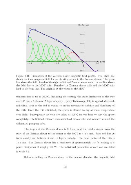
Figure 7.11: Simulation of the Zeeman slower magnetic field profile. The black l<strong>in</strong>e<br />
shows the ideal magnetic field for decelerat<strong>in</strong>g a<strong>to</strong>ms <strong>in</strong> the Zeeman slower. The green<br />
l<strong>in</strong>e shows the field of each of the eight <strong>in</strong>dividual Zeeman slower coils, the red l<strong>in</strong>e shows<br />
the field due <strong>to</strong> the MOT coils. Together the Zeeman slower coils <strong>and</strong> the MOT coils<br />
lead <strong>to</strong> the blue l<strong>in</strong>e. The orig<strong>in</strong> is at the center of the MOT.<br />
temperatures of up <strong>to</strong> 200 ◦ C. Includ<strong>in</strong>g the coat<strong>in</strong>g, the outer dimensions of the wire<br />
are 1.45 mm×1.45 mm. A layer of epoxy (Epoxy Technology, 360) is applied after each<br />
<strong>in</strong>dividual layer of the coil is wound <strong>to</strong> ensure mechanical stability <strong>and</strong> durability of<br />
the coils. Once the coil is f<strong>in</strong>ished, the epoxy is allowed <strong>to</strong> dry at room temperature<br />
over night. Subsequently the coils are baked at 100 ◦ C for one hour <strong>to</strong> cure the epoxy<br />
completely. The f<strong>in</strong>ished coils are then assembled on<strong>to</strong> a tube <strong>and</strong> mounted around the<br />
differential pump<strong>in</strong>g tube.<br />
600<br />
400<br />
200<br />
200<br />
The length of the Zeeman slower is 312 mm <strong>and</strong> the <strong>to</strong>tal distance from the<br />
start of the Zeeman slower <strong>to</strong> the center of the MOT is 414.7 mm. Each coil has 26<br />
turns axially <strong>and</strong> between 5 <strong>and</strong> 19 layers radially. The <strong>in</strong>ner radius of the coils is<br />
15.5 mm. The Zeeman slower has a resistance of approximately 3.5 Ω, lead<strong>in</strong>g <strong>to</strong> a<br />
power dissipation of roughly 120 W. The <strong>in</strong>dividual parameters of each coil are listed<br />
<strong>in</strong> table 7.1.<br />
Before attach<strong>in</strong>g the Zeeman slower <strong>to</strong> the vacuum chamber, the magnetic field<br />
103


