W POWER AND AUXILIARY CONTACTORS W MODULAR ...
W POWER AND AUXILIARY CONTACTORS W MODULAR ...
W POWER AND AUXILIARY CONTACTORS W MODULAR ...

Create successful ePaper yourself
Turn your PDF publications into a flip-book with our unique Google optimized e-Paper software.
ALEA<br />
CONNECTING COMPETENCE.<br />
W <strong>POWER</strong> <strong>AND</strong> <strong>AUXILIARY</strong> <strong>CONTACTORS</strong><br />
W <strong>MODULAR</strong> <strong>CONTACTORS</strong><br />
w MINIATUR <strong>POWER</strong> <strong>AND</strong> <strong>AUXILIARY</strong> <strong>CONTACTORS</strong><br />
w THERMAL OVERLOAD RELAYS<br />
W THERMAL OVERLOAD RELAYS FOR MINIATUR <strong>POWER</strong> <strong>CONTACTORS</strong><br />
W MOTOR PROTECTION SWITCHES UP TO 100A<br />
ENERGY INDUSTRY BUILDINGS SAFETY DATA CABLE LIGHT
GENERAL INFORMATION<br />
W WELCOME TO SCHRACK TECHNIK<br />
We are a leading, sales-oriented brand company from Austria specialising in the areas of energy, data and lighting systems.<br />
Our activities focus on products and solutions for energy optimisation, safety, data transfer and comfort. High-quality<br />
products, technical expertise and one-to-one customer service are at the fore of what we do.<br />
W SCHRACK PRODUCT QUALITY<br />
We offer our customers a well sorted product range offering the highest levels of product availability. Our aim is ultraefficiency<br />
when it comes to customerspecific solutions. This is possible thanks to standardized work processes, modularisation<br />
and the use of software aids.<br />
W SCHRACK ISO-CERTIFIZIED<br />
In recent times, testing procedures for ISO certification have shifted their focus very strongly on how organisations deal with<br />
customers, and the associated customer processes. Some of the major areas which are inspected include:<br />
General customer communication<br />
Dealing with offers and tenders in a structured manner<br />
Transparency in all areas of the company in direct or indirect contact with customers<br />
The above is required in all tiers of management<br />
ISO certification is by no means the norm. Our ISO certification 9001:2000 is both a reward as well as an obligation. The<br />
obligation we have in accepting this certification is to ensure the documentation of our work processes and to continuously<br />
improve such processes.<br />
W GENERAL INFORMATION<br />
All dimensioned drawings are displayed within the confines of available space on the page and are only intended as a guide.<br />
All circuit diagrams are schematic wiring diagrams which are intended to allow better understanding of the function, and<br />
will need to be edited/added to during the course of project planning.<br />
All images represent samples of the product and are intended for information purposes only.<br />
Unless otherwise stipulated, the current version of the General Terms of Delivery issued by The Association of the Austrian Electrical<br />
and Electronics Industries “FEEI” shall apply. No liability for errors in text, type or images; we reserve the right to make changes to technical<br />
specifications of the product range. The user information contained in this catalog reflect the opinion of the company at the time<br />
of writing. The information contained in it was assembled on the basis of published norms, specialist industry presentations, specialist<br />
literature and in-house expertise. The content is for informational purposes only and has no validity in law.
w ALEA <strong>POWER</strong> <strong>AND</strong> <strong>AUXILIARY</strong> <strong>CONTACTORS</strong><br />
INDEX<br />
OVERVIEW ................................................................................................................ Page 4<br />
GENERAL INFORMATIONS.......................................................................................... Page 13<br />
PRODUCTS <strong>AND</strong> ORDER NUMBERS ............................................................................ Page 18<br />
TECHNICAL SPECIFICATIONS ...................................................................................... Page 33<br />
DIMENSIONS ............................................................................................................ Page 100<br />
SCHEMATICS ............................................................................................................ Page 112<br />
w BZ <strong>MODULAR</strong> <strong>CONTACTORS</strong><br />
PRODUCTS <strong>AND</strong> ORDER NUMBERS ............................................................................ Page 124<br />
TECHNICAL SPECIFICATIONS ...................................................................................... Page 126<br />
DIMENSIONS ............................................................................................................ Page 129<br />
SCHEMATICS ............................................................................................................ Page 130<br />
w LA MINIATUR <strong>POWER</strong> <strong>AND</strong> <strong>AUXILIARY</strong> <strong>CONTACTORS</strong><br />
PRODUCTS <strong>AND</strong> ORDER NUMBERS ............................................................................ Page 134<br />
TECHNICAL SPECIFICATIONS ...................................................................................... Page 136<br />
DIMENSIONS ............................................................................................................ Page 139<br />
SCHEMATICS ............................................................................................................ Page 140<br />
w ALEA THERMAL OVERLOAD RELAYS<br />
OVERVIEW ................................................................................................................ Page 144<br />
GENERAL INFORMATIONS.......................................................................................... Page 146<br />
PRODUCTS <strong>AND</strong> ORDER NUMBERS ............................................................................ Page 149<br />
TECHNICAL SPECIFICATIONS ...................................................................................... Page 151<br />
ACCESSORIES............................................................................................................ Page 156<br />
CHARACTERISTIC CURVES .......................................................................................... Page 157<br />
DIMENSIONS ............................................................................................................ Page 158<br />
SCHEMATICS ............................................................................................................ Page 159<br />
w LA THERMAL OVERLOAD RELAYS FOR MINIATUR <strong>POWER</strong> <strong>CONTACTORS</strong><br />
PRODUCTS <strong>AND</strong> ORDER NUMBERS ............................................................................ Page 162<br />
TECHNICAL SPECIFICATIONS ...................................................................................... Page 163<br />
DIMENSIONS ............................................................................................................ Page 166<br />
SCHEMATICS ............................................................................................................ Page 167<br />
w ALEA MOTOR PROTECTION SWITCHES UP TO 100A<br />
OVERVIEW ................................................................................................................ Page 170<br />
GENERAL INFORMATIONS.......................................................................................... Page 173<br />
PRODUCTS <strong>AND</strong> ORDER NUMBERS ............................................................................ Page 176<br />
TECHNICAL SPECIFICATIONS ...................................................................................... Page 182<br />
ACCESSORIES............................................................................................................ Page 188<br />
CHARACTERISTIC CURVES .......................................................................................... Page 190<br />
DIMENSIONS ............................................................................................................ Page 191<br />
SCHEMATICS ............................................................................................................ Page 195<br />
w INDEX<br />
ALPHABETICAL INDEX ................................................................................................ Page 196<br />
LIST OF ARTICLES ...................................................................................................... Page 198<br />
Page<br />
1
Page<br />
2<br />
ALEA <strong>POWER</strong> <strong>AND</strong> <strong>AUXILIARY</strong> <strong>CONTACTORS</strong><br />
TOP-TECHNIC<br />
LSHD / LSHD-PLC<br />
TOP-TECHNIC<br />
LSD0 / LSS0-PLC<br />
TOP-TECHNIC<br />
TOP-TECHNIC<br />
LSDD / LSSD-PLC<br />
TOP-TECHNIC<br />
LSD2 / LSD3 / LSD6<br />
TOP-TECHNIC<br />
LSDE / LSDG LSDH
ALEA <strong>POWER</strong> <strong>AND</strong> <strong>AUXILIARY</strong> <strong>CONTACTORS</strong><br />
ALEA <strong>POWER</strong> <strong>AND</strong><br />
<strong>AUXILIARY</strong> <strong>CONTACTORS</strong><br />
w CONTENTS<br />
OVERVIEW .............................................................................................................. Page 4<br />
GENERAL INFORMATIONS ............................................................................ Page 13<br />
PRODUCTS <strong>AND</strong> ORDER NUMBERS ........................................................ Page 18<br />
TECHNICAL SPECIFICATIONS ...................................................................... Page 33<br />
DIMENSIONS ........................................................................................................ Page 100<br />
SCHEMATICS .......................................................................................................... Page 112<br />
Page<br />
3
Page<br />
4<br />
<strong>POWER</strong> <strong>AND</strong> <strong>AUXILIARY</strong> <strong>CONTACTORS</strong><br />
W <strong>CONTACTORS</strong> <strong>AND</strong> CONTACTOR ASSEMBLIES 3-POLE – OVERVIEW<br />
SIZE 00 00 0 2<br />
TYPE LSHD LSDD / LSSD 1) <strong>CONTACTORS</strong> <strong>AND</strong> VACUUM <strong>CONTACTORS</strong><br />
LSD0 / LSS0 LSD2<br />
TYPE / AC, DC OPERATION<br />
AC-3<br />
06 07 09 12 09 12 17 25 32 40 50<br />
Ie/AC-3/400 V 6A 7A 9A 12A 9A 12A 17A 25A 32A 40A 50A<br />
400 V 3A 3kW 4kW 5.5kW 4kW 5.5kW 7.5kW 11kW 15kW 18.5kW 22kW<br />
230 V -- 2.2kW 3kW 3kW 3kW 3kW 4kW 5.5kW 7.5kW 11kW 15kW<br />
500 V 2A 3.5kW 4.5kW 5.5kW 4.5kW 7.5kW 10kW 11kW 18.5kW 22kW 30kW<br />
690 V 1A 4kW 5.5kW 5.5kW 5.5kW 7.5kW 11kW 11kW 18.5kW 22kW 22kW<br />
1 000 V<br />
AC-4 (FOR IA = 6 X IE)<br />
-- -- -- -- -- -- -- -- -- -- --<br />
400 V -- 3kW 4kW 4kW 4kW 5.5kW 7.5kW 7.5kW 15kW 18.5kW 22kW<br />
400 V (200 000 operating cycles)<br />
AC-1 (40 °C, ≤ 690 V)<br />
-- 1.15kW 2kW 2kW 2kW 2.6kW 3.5kW 4.4kW 8.2kW 9.5kW 12.6kW<br />
Ie<br />
ACCESSORIES FOR <strong>CONTACTORS</strong><br />
10A 18A 22A 22A 40A 40A 40A 40A 50A 60A 60A<br />
<strong>AUXILIARY</strong> CONTACTS front LSZDH.. LSZDH.../LSZDD.../LSZD0 LSZ0D... LSZ0D...<br />
<strong>AND</strong> CONTACT BLOCKS LSZD0..<br />
lateral -- -- LSZ0D7.., LSZ0D9.. LSZ0D7.., LSZ0D9..<br />
TERMINAL COVERS -- -- -- LSZ2D...<br />
SURGE SUPPRESSORS LSZH0...<br />
OVERLOAD RELAYS (PROTECTION EQUIPMENT: OVERLOAD RELAYS)<br />
LSZD.... LSZ0.... LSZ2D....<br />
LST, thermal, Class 10 -- LSTD.... 0.1 ... 12 A LST0.... 2.5 ... 25 A LST2.... 10 ... 50 A<br />
MOTOR STARTER PROTECTORS (PROTECTION EQUIPMENT: MOTOR STARTER PROTECTORS)<br />
TYPE BES -- BESD 0.16 ... 12 A Size 00<br />
BESD 0.16 ... 12 A Size 0<br />
BES0 0.16 ... 25 A BES2 25 ... 50 A<br />
LINK MODULES LSZ<br />
REVERSING CONTACTOR ASSEMBLIES<br />
-- LSZDD005, LSZDD006 LSZ0D002 (AC), LSZ0D004 (DC) LSZ2D004 (AC), LSZ2D005 (DC)<br />
COMPLETE UNITS TYPE LSW -- LSWD07.. LSWD09.. LSWD12.. -- LSW012.. LSW017.. LSW025.. LSW232.. LSW240.. LSW250..<br />
400 V -- 3kW 4kW 5.5kW -- 5.5kW 7.5kW 12kW 15kW 18.5kW 22kW<br />
WIRING SETS -- LSZDW001 LSZDW001 LSZ2W001<br />
MECHANICAL INTERLOCKS<br />
CONTACTOR ASSEMBLIES FOR WYE-DELTA STARTING<br />
-- in wiring set included LSZ0W002 LSZ0W002<br />
COMPLETE UNITS TYPE LSY -- LSYD17.. LSY032.. LSY25033<br />
400 V -- 7.5kW 15kW 22kW<br />
WIRING SETS -- LSZDW001 LSZ0Y001 LSZ2Y003<br />
1) no auxillary contacts for PLC-use types possible<br />
LSHD / LSHD-PLC 1) LSDD / LSSD-PLC 1) LSD0 / LSS0-PLC LSD2
<strong>POWER</strong> <strong>AND</strong> <strong>AUXILIARY</strong> <strong>CONTACTORS</strong><br />
W <strong>CONTACTORS</strong> <strong>AND</strong> CONTACTOR ASSEMBLIES 3-POLE – OVERVIEW<br />
3 6 10 12 14<br />
LSD3 LSD6 LSDE LSDG LSDH<br />
65 80 95 11 15 2) 19 2) 22 26 30 41 51 63/64 82/83<br />
65A 80A 95A 115A 150A 185A 225A 265A 300A 400A 500A 630A 820A<br />
30kW 37kW 45kW 55kW 75kW 90kW 110kW 132kW 160kW 200kW 250kW 335kW 450kW<br />
18.5kW 22kW 22kW 37kW 45kW 55kW 55kW 75kW 90kW 132kW 160kW 200kW 260kW<br />
37kW 45kW 55kW 75kW 90kW 110kW 160kW 160kW 200kW 250kW 355kW 434kW 600kW<br />
45kW 55kW 55kW 110kW 132kW 160kW 200kW 250kW 250kW 400kW 400/500kW 600kW 800kW<br />
30kW 37kW 37kW 75kW 90kW 90kW 90/315kW 132/355kW 132/400kW 250/560kW 250/710kW 600kW 800kW<br />
30kW 37kW 45kW 55kW 75kW 90kW 110kW 132kW 160kW 200kW 250kW 335kW 450kW<br />
15.1kW 17.9kW 22kW 29kW 38kW 45kW 54/78kW 66/93kW 71/112kW 84/140kW 98/161kW 168kW 191kW<br />
100A 120A 120A 160A 185A 215A 275/330A 330A 330A 430/610A 610A 700A 910A<br />
LSZ0D... LSZ0D... LSZ0D... LSZ0D... --<br />
LSZ0D7.., LSZ3D8.., LSZ0D9.. LSZ0D7.., LSZ3D8.., LSZ0D9.. LSZ0D7.., LSZ3D8.., LSZ0D9.. LSZ0D7.., LSZ3D8.., LSZ0D9.. --<br />
LSZ3D... LSZ6D... LSZED... LSZED... LSZHD...<br />
LSZ2.... LSZ6.... LSZ6.... LSZ6.... included<br />
LST3 25 ... 100 A -- -- -- --<br />
BES3 63 ... 100 A -- -- -- --<br />
LS3D003 (AC), LS3D004 (DC)<br />
LSW365.. LSW380.. LSW395.. -- -- -- --<br />
30kW 37kW 45kW -- -- -- --<br />
LSZ3W001 -- -- -- --<br />
LSZ0W002 -- -- -- --<br />
-- -- -- -- --<br />
-- -- -- -- --<br />
-- -- -- -- --<br />
2) without box-terminals<br />
LSD3 LSD6 LSDE LSDG LSDH<br />
Page<br />
5
Page<br />
6<br />
<strong>POWER</strong> <strong>AND</strong> <strong>AUXILIARY</strong> <strong>CONTACTORS</strong><br />
W LSDD <strong>CONTACTORS</strong>, LSSD <strong>CONTACTORS</strong> FOR PLC-USE <strong>AND</strong><br />
LSHD <strong>AUXILIARY</strong> <strong>CONTACTORS</strong> – OVERVIEW<br />
W SIZE 00 WITH MOUNTABLE ACCESSORIES<br />
The ALEA generation of controls is a complete, modular system family, logically designed right down to the last detail, from<br />
the basic units to the accessories.<br />
1. Contactor LSDD<br />
2. Contactor LSSD and auxiliary contactors LSHD<br />
8. 1-pole auxiliary contact block, cable entry from below<br />
10. 4-pole auxiliary contact block (terminal designations<br />
according to EN 50005 and EN 50012)<br />
13. Solder pin adapter for contactors and auxiliary contactors<br />
16. Surge suppressor<br />
17. 3-phase feeder terminal<br />
18. Link for paralleling (star jumper), 3-pole, without terminal<br />
19. Link for paralleling, 3-pole, with terminal<br />
20. Link for paralleling, 4-pole, with terminal<br />
For contactors LSDD<br />
For LSSD contactors for PLC-use and<br />
LSHD auxiliary contactors
<strong>POWER</strong> <strong>AND</strong> <strong>AUXILIARY</strong> <strong>CONTACTORS</strong><br />
W LSD0, LSD2, LSD3 <strong>AND</strong> LSS0 <strong>CONTACTORS</strong> FOR PLC-USE – OVERVIEW<br />
W SIZES 0 TO 3 WITH MOUNTABLE ACCESSORIES<br />
For sizes 0 to 3:<br />
1. Contactor, size 0<br />
2. Contactor, size 2<br />
3. Contactor, size 3<br />
9. 4-pole auxiliary contact block (terminal designations<br />
according to EN 50005 and EN 50012)<br />
10. Link for paralleling (star jumper), 3-pole, without<br />
connection terminal<br />
11. Link for paralleling, 3-pole, with terminal<br />
12. 2-pole auxiliary contact block, laterally mountable left or<br />
right (terminal designations according to EN 50012)<br />
13. Single-pole auxiliary contact (up to 4 can be snapped on)<br />
14. Mechanical interlock, laterally mountable<br />
16. Wiring modules on the top and bottom (reversing duty)<br />
17. Surge suppressor (varistor, RC element, diode assembly),<br />
can be mounted on the top or bottom (different for<br />
size 0, 2 and 3)<br />
Only for sizes 2 and 3:<br />
22. Terminal cover for box terminals<br />
Only for size 3:<br />
23. Terminal cover for cable lugs and busbar connections<br />
24. Auxiliary conductor terminal, 3-pole<br />
Accessories identical for sizes 0 to 3<br />
Accessories different according to size<br />
Page<br />
7
Page<br />
8<br />
<strong>POWER</strong> <strong>AND</strong> <strong>AUXILIARY</strong> <strong>CONTACTORS</strong><br />
W LSD6, LSDE <strong>AND</strong> LSDG <strong>CONTACTORS</strong> – OVERVIEW<br />
W SIZES 6 TO 12 WITH ACCESSORIES<br />
1. LSD6, LSDE, LSDG contactors, sizes 6, 10 and 12<br />
3. 4-pole auxiliary contact block (terminal designations<br />
according to EN 50005 and EN 50012)<br />
6. Single-pole auxiliary contact (up to 4 can be snapped on)<br />
7. 2-pole auxiliary contact block, laterally mountable left or<br />
right (terminal designations according to EN 50012)<br />
(identical for sizes 0 to 12)<br />
8. Surge suppressor (RC element), for plugging into top of<br />
withdrawable coil<br />
9. Terminal cover for cable lug and busbar connection,<br />
different for sizes 6, 10 and 12<br />
10. Terminal cover for box terminal, different for sizes 6, 10<br />
and 12<br />
11. Box terminal block, different for sizes 6, 10 and 12<br />
Accessories identical for sizes 0 to 12<br />
Accessories identical for sizes 6 to 12<br />
Accessories different according to size
W LSD <strong>CONTACTORS</strong> – OVERVIEW<br />
<strong>POWER</strong> <strong>AND</strong> <strong>AUXILIARY</strong> <strong>CONTACTORS</strong><br />
W LSW CONTACTOR ASSEMBLIES, LSD <strong>CONTACTORS</strong> SIZE 6 WITH ACCESSORIES<br />
1. LSD contactors, size 6<br />
2. Mechanical interlock, laterally mountable<br />
3. Wiring modules on the top and bottom<br />
4. Link for paralleling (star jumper), 3-pole, with through<br />
hole<br />
5. Terminal cover for cable lug and busbar connection,<br />
different for sizes 6, 10 and 12<br />
6. Terminal cover for box terminal, different for sizes 6, 10<br />
and 12<br />
7. Box terminal block, different for sizes 6, 10 and 12<br />
Accessories identical for sizes 6 to 12<br />
Accessories different according to size<br />
Page<br />
9
Page<br />
10<br />
<strong>POWER</strong> <strong>AND</strong> <strong>AUXILIARY</strong> <strong>CONTACTORS</strong><br />
W LSDE <strong>AND</strong> LSDG <strong>CONTACTORS</strong> – OVERVIEW<br />
W LSW CONTACTOR ASSEMBLIES, LSD <strong>CONTACTORS</strong> SIZE 10 <strong>AND</strong> 12 WITH ACCESSORIES<br />
1. LSD contactors, sizes 10 and 12 or LSD<br />
2. Mechanical interlock, laterally mountable<br />
3. Wiring modules on the top and bottom<br />
4. Link for paralleling (star jumper), 3-pole, with through<br />
hole<br />
5. Terminal cover for box terminal, different for sizes 6, 10<br />
and 12<br />
6. Terminal cover for cable lug and busbar connection,<br />
different for sizes 6, 10 and 12<br />
Accessories identical for sizes 6 to 12<br />
Accessories different according to size
W LSD <strong>CONTACTORS</strong> – OVERVIEW<br />
W LSD <strong>CONTACTORS</strong> SIZES 6 TO 12 WITH ACCESSORIES<br />
1. LSD6, LSDE, LSDG contactors, sizes 6, 10 and 12<br />
3. Withdrawable coils for LSD contactors with conventional<br />
operating mechanism<br />
6. Surge suppressor (RC element), plug-mountable on<br />
withdrawable coils<br />
<strong>POWER</strong> <strong>AND</strong> <strong>AUXILIARY</strong> <strong>CONTACTORS</strong><br />
Identical for sizes 6 to 12<br />
Different according to size<br />
Page<br />
11
Page<br />
12<br />
<strong>POWER</strong> <strong>AND</strong> <strong>AUXILIARY</strong> <strong>CONTACTORS</strong><br />
W LSHD <strong>AUXILIARY</strong> <strong>CONTACTORS</strong> – OVERVIEW<br />
The ALEA generation of controls is a complete, modular system family, logically designed right down to the last detail, from<br />
the basic units to the accessories.<br />
W AC <strong>AND</strong> DC OPERATION<br />
IEC 60947, EN 60947 (VDE 0660)<br />
The LSHD Auxiliary contactors are suitable for use in any climate. They are finger-safe according to EN 50274.<br />
The LSHD Auxiliary contactors have screw or Cage Clamp terminals. Four contacts are available in the basic unit.<br />
(Cage Clamp on request)<br />
W <strong>AUXILIARY</strong> <strong>CONTACTORS</strong> SIZE 00, WITH ACCESSORIES<br />
1. Auxiliary contactor<br />
2. Auxiliary contactor for PLC-use<br />
8. 1-pole auxiliary contact block, cable entry from below<br />
10. 4-pole auxiliary contact block (terminal designations according to EN 50005)<br />
13. Solder pin adapter for aux iliary<br />
contactor<br />
16. Surge suppressor
<strong>POWER</strong> <strong>AND</strong> <strong>AUXILIARY</strong> <strong>CONTACTORS</strong><br />
W LSD <strong>CONTACTORS</strong> FOR SWITCHING MOTORS, 3-POLE, 3 ... 250 kW –<br />
GENERAL INFORMATIONS<br />
W LSD <strong>CONTACTORS</strong>, 3-POLE, SIZES 00 TO 3, UP TO 45 kW<br />
AC <strong>AND</strong> DC OPERATION<br />
IEC 60947, EN 60947 (VDE 0660). The LSD contactors are climate-proof. They are finger-safe according to EN 50274. Size<br />
size 00 contactors have an auxiliary contact integrated in the basic unit. The basic units of sizes 0 to 3 contain only the main<br />
current paths. All basic units can be extended with auxiliary contacts and contact blocks.<br />
CONNECTION METHODS<br />
The LSD contactors are available with screw terminals (box terminals and connecting bars) or with Cage Clamp terminals.<br />
The size 3 contactors have removable box terminals for the main conductor connections. This permits connection of ring<br />
terminal lugs or busbars.<br />
CONTACT RELIABILITY<br />
If voltages ≤ 110 V and current ≤ 100 mA are to be switched, the auxiliary contacts of the LSD contactor or LSH auxiliary<br />
contactor should be used as they guarantee a high level of contact reliability. These auxiliary contacts are suitable for solidstate<br />
circuits with currents ≥ 1 mA at a voltage of 17 V.<br />
SHORT-CIRCUIT PROTECTION OF THE <strong>CONTACTORS</strong><br />
Short-circuit protection of the contactors without overload relay, see Technical specifications. For short-circuit protection of<br />
the contactors with overload relay, see "Thermal Overload Relays". To assemble fuseless motor feeders you must select<br />
combinations of motor protection switches (MPS) and contactor.<br />
MOTOR PROTECTION<br />
LST thermal overload relays can be fitted to the LSD contactors for protection against overload. The overload relays must be<br />
ordered separately.<br />
RATINGS OF INDUCTION MOTORS<br />
The quoted rating (in kW) refers to the output power on the motor shaft (according to the nameplate).<br />
SURGE SUPPRESSION<br />
LSD contactors can be retrofitted with RC elements, varistors, diodes or diode assemblies (assembly of diode and Zener diode<br />
for short break times) for damping opening surges in the coil. The surge suppressors are plugged onto the front of size 00<br />
contactors. Space is provided for them next to a snap-on auxiliary contact block. For sizes 0 to 3 contactors, varistors and<br />
RC elements can be snapped on either on the top or directly below the coil terminals. Diode assemblies are available in 2<br />
different versions on account of their polarity. Depending on the application they can be connected either only at the<br />
bottom (assembly with MPS) or only at the top (assembly with overload relay). The plug-in direction of the diodes and diode<br />
assemblies is specified by coding.<br />
Exceptions:<br />
LSZD0006, in this case the plug-in direction is marked with "+" and "-"<br />
Auxiliary contactors are supplied either without surge suppression or with a varistor or diode connected as standard,<br />
according to the version.<br />
Note:<br />
The OFF-delay times of the NO contacts and the ON-delay times of the NC contacts increase if the contactor coils are<br />
damped against voltage peaks (noise suppression diode 6 to 10 times; diode assemblies 2 to 6 times, varistor +2 to 5 ms).<br />
Page<br />
13
Page<br />
14<br />
<strong>POWER</strong> <strong>AND</strong> <strong>AUXILIARY</strong> <strong>CONTACTORS</strong><br />
W LSD <strong>CONTACTORS</strong> FOR SWITCHING MOTORS, 3-POLE, 3 ... 250 kW –<br />
GENERAL INFORMATIONS<br />
W LSD <strong>CONTACTORS</strong>, 3-POLE, SIZES 6 TO 12, > 45 TO 250 kW<br />
LSD contactors for switching motors<br />
LSR contactors for AC-1 applications<br />
UC OPERATION<br />
The contactors can be operated with AC (40 to 60 Hz) as well as with DC.<br />
WITHDRAWABLE COILS<br />
For simple coil replacement, e.g. if the application is replaced, the magnetic coil can be pulled out upwards after the release<br />
mechanism has been actuated and can be replaced by any other coil of the same size.<br />
<strong>AUXILIARY</strong> CONTACT COMPLEMENT<br />
The contactors can be fitted with up to 8 auxiliary contacts (identical auxiliary contact blocks from sizes 0 to 12). Of these,<br />
no more than 4 are permitted to be NC contacts.<br />
The magnetic coil is switched directly on and off with the control supply voltage Us by way of terminals A1/A2.<br />
MULTI-VOLTAGE RANGE FOR THE CONTROL SUPPLY VOLTAGE U S:<br />
Several closely adjacent control supply voltages, available around the world, are covered by just one coil, for example<br />
110-115-120-127 V UC or 220-230-240 V UC. In addition, allowance is also made for a coil operating range of 0.8 times<br />
the lower (Us min) and 1.1 times the upper (Us max) rated control supply voltage within which the contactor switches<br />
reliably and no thermal overloading occurs.
<strong>POWER</strong> <strong>AND</strong> <strong>AUXILIARY</strong> <strong>CONTACTORS</strong><br />
W LSS, LSD <strong>CONTACTORS</strong> FOR SWITCHING MOTORS, 3-POLE, 3 ... 250 kW –<br />
GENERAL INFORMATIONS<br />
W <strong>AUXILIARY</strong> CONTACT BLOCKS<br />
Various auxiliary contact blocks can be added to the contactor basic units depending on the application:<br />
W SIZE 00<br />
LSSD, LSDD <strong>CONTACTORS</strong><br />
Terminal designations according to EN 50012.<br />
W SIZES 0 TO 12<br />
with 1 NO with 1 NC<br />
LSZDD201,212,213,222 LSZDH540,531,522<br />
LSZD0501,510<br />
LSD0 TO LSDG <strong>CONTACTORS</strong>, 1-POLE <strong>AUXILIARY</strong> CONTACTS<br />
Terminal designations according to EN 50012.<br />
LSZ0D010<br />
LSZ0D910<br />
(early make)<br />
contactors<br />
size 0 to 12<br />
LSZ0D001<br />
LSZ0D901<br />
(delayed)<br />
Size 00 contactors have an auxiliary contact integrated in the basic<br />
unit.<br />
Contactors with a NO contact as auxiliary contact with screw or Cage<br />
Clamp terminals, can be expanded into contactors with 2, 4 and 5<br />
auxiliary contacts according to EN 50012 using auxiliary contact blocks.<br />
These auxiliary contact blocks cannot be combined with contactors<br />
which have a NC contact in the basic unit as they are coded.<br />
LSZD0501,510 single-auxiliary contact blocks with connection options<br />
from below enable easy and clearly arranged wiring especially for the<br />
installation of network access junctions. These auxiliary contact blocks<br />
are offered only with screw terminals.<br />
All the previously mentioned auxiliary contact variants can be snapfitted<br />
onto the front of the contactor. The auxiliary contact block has<br />
a centrally positioned release lever for disassembly.<br />
The terminal designations of the single-pole auxiliary contacts<br />
are comprised of sequence numbers (location identifiers) on<br />
the contactor (1...4) and of function numbers on the auxiliary<br />
contacts (.1/.2, .3/.4 or .5/.6, .7/.8).<br />
The terminal designation of these individual auxiliary contacts<br />
corresponds to EN 50005 and EN 50012.<br />
Page<br />
15
Page<br />
16<br />
<strong>POWER</strong> <strong>AND</strong> <strong>AUXILIARY</strong> <strong>CONTACTORS</strong><br />
W LSD <strong>CONTACTORS</strong> FOR SWITCHING MOTORS, 3-POLE, 3 ... 250 kW –<br />
GENERAL INFORMATIONS<br />
W SIZES 0 TO 12<br />
LSD0 TO LSDG <strong>CONTACTORS</strong>, 4-POLE <strong>AUXILIARY</strong> CONTACT BLOCKS<br />
Terminal designations according to EN 50012.<br />
W SIZES 0 <strong>AND</strong> 2<br />
A maximum of 4 auxiliary contacts can be attached; the auxiliary contact blocks used can be of any version. For reasons of<br />
symmetry, when two 2-pole laterally mountable auxiliary contact blocks are used, one block must be attached on the right<br />
and one on the left. More auxiliary contacts are permissible with size 2 under certain conditions (please ask). For 4-pole<br />
contactors see LSR...<br />
W SIZES 3 TO 12<br />
contactors<br />
size 0 to 12<br />
LSZ0D131,122,113 LSZ0D140F.,122F.,131F.,104F.<br />
A maximum of 8 auxiliary contacts can be attached; please note the following:<br />
Of these 8 auxiliary contacts, there must be no more than 4 NC contacts<br />
Ensure the symmetry of laterally mounted auxiliary contact blocks<br />
For 4-pole contactors see LSR...<br />
The contactors themselves have no integrated auxiliary<br />
conducting path.<br />
The auxiliary contact variants are uniform for the<br />
contactors of size 0 to 12.<br />
One 4-pole or up to four single-pole auxiliary contact blocks<br />
(screw or Cage Clamp terminals) can be snapped on. When<br />
the contactors are switched on, the NC contacts are opened<br />
first and then the NO contacts are closed.<br />
If the installation space is limited in depth, 2-pole auxiliary<br />
contact blocks (screw or Cage Clamp terminals) can be<br />
attached laterally for use on the left or on the right (LSZ0D711,<br />
LSZ3D811).<br />
The auxiliary contact blocks attached to the front can be disassembled<br />
with the help of a centrally arranged release lever;<br />
the laterally attached auxiliary contact blocks are easy to<br />
remove by pressing on the checkered surfaces.<br />
The laterally attachable auxiliary contact blocks according to<br />
EN 50012 can be used only when no 4-pole auxiliary contact<br />
blocks are snapped onto the front. If single-pole auxiliary<br />
contact blocks are used in addition, the location identifiers on<br />
the contactor must be noted.
<strong>POWER</strong> <strong>AND</strong> <strong>AUXILIARY</strong> <strong>CONTACTORS</strong><br />
W LSHD <strong>AUXILIARY</strong> <strong>CONTACTORS</strong> – GENERAL INFORMATIONS<br />
W CONTACT RELIABILITY<br />
High contact stability at low voltages and currents, suitable for solid-state circuits with currents ≥ 1 mA at a voltage of 17 V.<br />
W SURGE SUPPRESSION<br />
RC elements, varistors, diodes or diode assemblies (combination of a diode and a Zener diode) can be plugged onto all<br />
auxiliary contactors from the front for damping opening surges in the coil. The plug-in direction is determined by a coding<br />
device.<br />
Note:<br />
The OFF-delay times of the NO contacts and the ON-delay times of the NC contacts increase if the contactor coils are damped<br />
against voltage peaks (noise suppression diode 6 to 10 times; diode assemblies 2 to 6 times, varistor +2 to 5 ms).<br />
W <strong>AUXILIARY</strong> CONTACT BLOCKS<br />
The LSHD auxiliary contactors can be expanded by up to four contacts by the addition of mountable auxiliary contact blocks.<br />
The auxiliary contact block can easily be snapped onto the front of the contactors. The auxiliary contact block has a centrally<br />
positioned release lever for disassembly. All auxiliary contactors with 4 contacts according to EN 50011 can be extended with<br />
auxiliary contact blocks to obtain auxiliary contactors with 5 or 8 contacts in accordance with EN 50005.<br />
Aux. contactors,<br />
EN 50 011, 4 contacts<br />
4NO; 3NO + 1NC;<br />
2NO + 2NC<br />
Aux. contact blocks<br />
EN 50 005,<br />
4 or 1 contacts<br />
LSZDH540,531,522<br />
LSZD0501,510<br />
Page<br />
17
Page<br />
18<br />
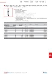
<strong>POWER</strong> <strong>AND</strong> <strong>AUXILIARY</strong> <strong>CONTACTORS</strong><br />
W LSD <strong>CONTACTORS</strong> FOR SWITCHING MOTORS AC3 – 3POLE, SIZE 00<br />
LSDD.... LSSD....-PLC<br />
DESCRIPTION COIL VOLTAGE FREQU/REMARK ORDER NO.<br />
SIZE 00 – TYPE LSDD<br />
Contactor AC3:3KW/400V, 1NO AC24V 50HZ LSDD0710<br />
Contactor AC3:3KW/400V, 1NC* AC24V 50HZ LSDD0720<br />
Contactor AC3:3KW/400V, 1NO AC110V 50HZ LSDD0712<br />
Contactor AC3:3KW/400V, 1NC* AC110V 50HZ LSDD0722<br />
Contactor AC3:3KW/400V, 1NO AC230V 50/60HZ LSDD0713<br />
Contactor AC3:3KW/400V, 1NC* AC230V 50/60HZ LSDD0723<br />
Contactor AC3:3KW/400V, 1NO DC24V LSDD0715<br />
Contactor AC3:3KW/400V, 1NC* DC24V LSDD0725<br />
Contactor AC3:4KW/400V, 1NO AC24V 50HZ LSDD0910<br />
Contactor AC3:4KW/400V, 1NC* AC24V 50HZ LSDD0920<br />
Contactor AC3:4KW/400V, 1NO AC110V 50HZ LSDD0912<br />
Contactor AC3:4KW/400V, 1NC* AC110V 50HZ LSDD0922<br />
Contactor AC3:4KW/400V, 1NO AC230V 50/60HZ LSDD0913<br />
Contactor AC3:4KW/400V, 1NC* AC230V 50/60HZ LSDD0923<br />
Contactor AC3:4KW/400V, 1NO DC24V LSDD0915<br />
Contactor AC3:4KW/400V, 1NC* DC24V LSDD0925<br />
Contactor AC3:5,5KW/400V, 1NO AC24V 50HZ LSDD1210<br />
Contactor AC3:5,5KW/400V, 1NC* AC24V 50HZ LSDD1220<br />
Contactor AC3:5,5KW/400V, 1NO AC110V 50HZ LSDD1212<br />
Contactor AC3:5,5KW/400V, 1NC* AC110V 50HZ LSDD1222<br />
Contactor AC3:5,5KW/400V, 1NO AC230V 50/60HZ LSDD1213<br />
Contactor AC3:5,5KW/400V, 1NC* AC230V 50/60HZ LSDD1223<br />
Contactor AC3:5,5KW/400V, 1NO DC24V LSDD1215<br />
Contactor AC3:5,5KW/400V, 1NC* DC24V LSDD1225<br />
SIZE 00 – TYPE LSSD FOR PLC<br />
W SCHRACK-INFO<br />
Auxiliary contact block types LSZD.... can be snapped on contactors<br />
LSDD.... Contactors for PLC cannot be extended by further<br />
auxiliary contacts. Suitable surge supressor types LSZD0001 to<br />
LSZD0004.<br />
Contactor AC3:3KW/400V, 1NO DC17-30V no further aux. contacts LSSD071G<br />
Contactor AC3:3KW/400V, 1NC DC17-30V no further aux. contacts LSSD072G<br />
Contactor AC3:4KW/400V, 1NO DC17-30V no further aux. contacts LSSD091G<br />
Contactor AC3:4KW/400V, 1NC DC17-30V no further aux. contacts LSSD092G<br />
Contactor AC3:5,5KW/400V, 1NO DC17-30V no further aux. contacts LSSD121G<br />
Contactor AC3:5,5KW/400V, 1NC<br />
* Only auxiliary contact block type LSZDH5.. and LSZD05.. possible<br />
DC17-30V no further aux. contacts LSSD122G
<strong>POWER</strong> <strong>AND</strong> <strong>AUXILIARY</strong> <strong>CONTACTORS</strong><br />
W LSD <strong>CONTACTORS</strong> FOR SWITCHING MOTORS AC3 – 3POLE, SIZE 0<br />
LSD0....<br />
DESCRIPTION COIL VOLTAGE FREQU/REMARK ORDER NO.<br />
SIZE 0 – TYPE LSD0<br />
Contactor AC3:4KW/400V AC24V 50HZ LSD00930<br />
Contactor AC3:4KW/400V DC24V LSD00935<br />
Contactor AC3:4KW/400V AC110V 50HZ LSD00932<br />
Contactor AC3:4KW/400V AC230V 50/60HZ LSD00933<br />
Contactor AC3:5,5KW/400V AC24V 50HZ LSD01230<br />
Contactor AC3:5,5KW/400V DC24V LSD01235<br />
Contactor AC3:5,5KW/400V AC110V 50HZ LSD01232<br />
Contactor AC3:5,5KW/400V AC230V 50/60HZ LSD01233<br />
Contactor AC3:7,5KW/400V AC24V 50HZ LSD01730<br />
Contactor AC3:7,5KW/400V DC24V LSD01735<br />
Contactor AC3:7,5KW/400V AC110V 50HZ LSD01732<br />
Contactor AC3:7,5KW/400V AC230V 50/60HZ LSD01733<br />
Contactor AC3:7,5KW/400V AC400V 50HZ LSD01734<br />
Contactor AC3:11KW/400V AC24V 50HZ LSD02530<br />
Contactor AC3:11KW/400V DC24V LSD02535<br />
Contactor AC3:11KW/400V AC110V 50HZ LSD02532<br />
Contactor AC3:11KW/400V AC230V 50/60HZ LSD02533<br />
SIZE 0 – TYPE LSS0 FOR PLC<br />
W SCHRACK-INFO<br />
Auxiliary contact and contact block types LSZ0D... can be snapped on. Suitable surge<br />
supressor types LSZD0005, LSZD0006 and LSZ00001 to LSZ00003.<br />
Contactor AC3,5,5KW/400V* DC17-30V LSS0123H<br />
Contactor AC3:7,5KW/400V* DC17-30V LSS0173H<br />
Contactor AC3:11KW/400V* DC17-30V LSS0253H<br />
* Max. 2 pcs. of auxiliary contact type LSZ0D0.. or LSZ0D9.. possible<br />
Page<br />
19
Page<br />
20<br />
LSD3....<br />
<strong>POWER</strong> <strong>AND</strong> <strong>AUXILIARY</strong> <strong>CONTACTORS</strong><br />
W LSD <strong>CONTACTORS</strong> FOR SWITCHING MOTORS AC3 – 3POLE, SIZE 2<br />
LSD2....<br />
DESCRIPTION COIL VOLTAGE FREQU/REMARK ORDER NO.<br />
SIZE 2 – TYPE LSD2<br />
W LSD <strong>CONTACTORS</strong> FOR SWITCHING MOTORS AC3 – 3POLE, SIZE 3<br />
DESCRIPTION COIL VOLTAGE FREQU/REMARK ORDER NO.<br />
SIZE 3 – TYPE LSD3<br />
W SCHRACK-INFO<br />
Auxiliary contact and contact block types LSZ0D... can be snapped on. Suitable surge<br />
supressor types LSZ20001 for AC 230V.<br />
Contactor AC3:15KW/400V AC24V 50HZ LSD23230<br />
Contactor AC3:15KW/400V DC24V LSD23235<br />
Contactor AC3:15KW/400V AC110V 50HZ LSD23232<br />
Contactor AC3:15KW/400V AC230V 50/60HZ LSD23233<br />
Contactor AC3:18,5KW/400V AC24V 50HZ LSD24030<br />
Contactor AC3:18,5KW/400V DC24V LSD24035<br />
Contactor AC3:18,5KW/400V AC110V 50HZ LSD24032<br />
Contactor AC3:18,5KW/400V AC230V 50/60HZ LSD24033<br />
Contactor AC3:22KW/400V AC24V 50HZ LSD25030<br />
Contactor AC3:22KW/400V DC24V LSD25035<br />
Contactor AC3:22KW/400V AC110V 50HZ LSD25032<br />
Contactor AC3:22KW/400V AC230V 50/60HZ LSD25033<br />
W SCHRACK-INFO<br />
Auxiliary contact and contact block types LSZ0D... and LSZ3D... can be snapped on. Suitable<br />
surge supressor types LSZ20001 for AC 230V.<br />
Contactor AC3:30KW/400V AC24V 50HZ LSD36530<br />
Contactor AC3:30KW/400V DC24V LSD36535<br />
Contactor AC3:30KW/400V AC110V 50HZ LSD36532<br />
Contactor AC3:30KW/400V AC230V 50/60HZ LSD36533<br />
Contactor AC3:30KW/400V, 2NO+2NC AC230V 50HZ LSD36553<br />
Contactor AC3:37KW/400V AC24V 50HZ LSD38030<br />
Contactor AC3:37KW/400V DC24V LSD38035<br />
Contactor AC3:37KW/400V, 2NO+2NC AC24V 50HZ LSD38050<br />
Contactor AC3:37KW/400V AC110V 50HZ LSD38032<br />
Contactor AC3:37KW/400V, 2NO+2NC AC110V 50HZ LSD38052<br />
Contactor AC3:37KW/400V AC230V 50/60HZ LSD38033<br />
Contactor AC3:45KW/400V AC24V 50HZ LSD39530<br />
Contactor AC3:45KW/400V DC24V LSD39535<br />
Contactor AC3:45KW/400V AC230V 50/60HZ LSD39533<br />
Contactor AC3:45KW/400V, 2NO+2NC AC230V 50/60HZ LSD39553
LSD6115F LSD6155F LSDE305F<br />
<strong>POWER</strong> <strong>AND</strong> <strong>AUXILIARY</strong> <strong>CONTACTORS</strong><br />
W LSD <strong>CONTACTORS</strong> FOR SWITCHING MOTORS AC3 – 3POLE, SIZE 6/10/12<br />
DESCRIPTION COIL VOLTAGE FREQU/REMARK ORDER NO.<br />
SIZE 6 – TYPE LSD6<br />
Contactor AC3:55KW/400V, 2NO+2NC (with box terminals) UC220-240V 40-60HZ LSD6115F<br />
Contactor AC3:75KW/400V, 2NO+2NC UC220-240V 40-60HZ LSD6155F<br />
Contactor AC3:90KW/400V, 2NO+2NC UC220-240V 40-60HZ LSD6195F<br />
SIZE 10 – TYPE LSDE<br />
Contactor AC3:110KW/400V, 2NO+2NC UC220-240V 40-60HZ LSDE225F<br />
Contactor AC3:132KW/400V, 2NO+2NC UC220-240V 40-60HZ LSDE265F<br />
Contactor AC3:160KW/400V, 2NO+2NC UC220-240V 40-60HZ LSDE305F<br />
SIZE 12 – TYPE LSDG<br />
Contactor AC3:200KW/400V, 2NO+2NC UC220-240V 40-60HZ LSDG415F<br />
Contactor AC3:250KW/400V, 2NO+2NC UC220-240V 40-60HZ LSDG515F<br />
W LSD VACUUM <strong>CONTACTORS</strong> AC3 – 3POLE, SIZE 14<br />
LSDH....<br />
DESCRIPTION COIL VOLTAGE FREQU/REMARK ORDER NO.<br />
SIZE 14 – TYPE LSDH<br />
W SCHRACK-INFO<br />
LSD6115F fitted with box terminals<br />
up to 70 mm2 , all other types<br />
without box terminals. Those box<br />
terminals are deliverable on request.<br />
Auxiliary contact and contact block<br />
types LSZ0D... and LSZ3D... can be<br />
snapped on. Suitable surge supressor<br />
type LSZ60001.<br />
W SCHRACK-INFO<br />
Contactors cannot be extended by further auxiliary contacts. Surge supressor by means of a<br />
varistor circuit is included in the scope of supply.<br />
Contactor AC3:335KW/400V, 4NO+4NC UC200-240V 50HZ LSDH63G3<br />
Contactor AC3:335KW/1000V, 4NO+4NC UC200-240V 50HZ LSDH64G3<br />
Contactor AC3:450KW/400V, 4NO+4NC UC200-240V 50HZ LSDH82G3<br />
Contactor AC3:450KW/1000V, 4NO+4NC UC200-240V 50HZ LSDH83G3<br />
Page<br />
21
Page<br />
22<br />
LSWD....<br />
<strong>POWER</strong> <strong>AND</strong> <strong>AUXILIARY</strong> <strong>CONTACTORS</strong><br />
W LSW REVERSING CONTACTOR ASSEMBLIES AC3, SIZE 00/0/2/3<br />
DESCRIPTION COIL VOLTAGE FREQU/REMARK ORDER NO.<br />
SIZE 00 – TYPE LSWD<br />
Reversing Assembly AC3, 3kW/400V 230V 50/60HZ LSWD0733<br />
Reversing Assembly AC3, 4kW/400V 230V 50/60HZ LSWD0933<br />
Reversing Assembly AC3, 5,5kW/400V 230V 50/60HZ LSWD1233<br />
SIZE 0 – TYPE LSW0<br />
Reversing Assembly AC3, 5,5kW/400V 230V 50/60HZ LSW01233<br />
Reversing Assembly AC3, 7,5kW/400V 230V 50/60HZ LSW01733<br />
Reversing Assembly AC3, 11kW/400V 230V 50/60HZ LSW02533<br />
SIZE 2 – TYPE LSW2<br />
Reversing Assembly AC3, 15kW/400V 230V 50/60HZ LSW23233<br />
Reversing Assembly AC3, 18,5kW/400V 230V 50/60HZ LSW24033<br />
Reversing Assembly AC3, 22kW/400V 230V 50/60HZ LSW25033<br />
SIZE 3 – TYPE LSW3<br />
Reversing Assembly AC3, 30kW/400V 230V 50/60HZ LSW36533<br />
Reversing Assembly AC3, 37kW/400V 230V 50/60HZ LSW38033<br />
Reversing Assembly AC3, 45kW/400V 230V 50/60HZ LSW39533<br />
W LSY WYE-DELTA CONTACTOR ASSEMBLIES AC3, SIZE 00/0/2<br />
LSY03233<br />
DESCRIPTION COIL VOLTAGE FREQU/REMARK ORDER NO.<br />
SIZE 00 – TYPE LSYD<br />
WYE-Delta Assembly AC3, up to 7,5kW/400V 230V 50/60HZ LSYD1733<br />
SIZE 0 – TYPE LSY0<br />
WYE-Delta Assembly AC3, up to 15kW/400V 230V 50/60HZ LSY03233<br />
SIZE 2 – TYPE LSY2<br />
LSW0....<br />
W SCHRACK-INFO<br />
For higher ratings or customer assembly see components listed<br />
on pages onwards.<br />
W SCHRACK-INFO<br />
For higher ratings or customer assembly see components listed on pages onwards.<br />
WYE-Delta Assembly AC3, up to 22kW/400V 230V 50/60HZ LSY25033
<strong>POWER</strong> <strong>AND</strong> <strong>AUXILIARY</strong> <strong>CONTACTORS</strong><br />
W LSR <strong>CONTACTORS</strong> FOR SWITCHING AC1 LOADS – 4POLE, SIZE 00/0<br />
LSR0....<br />
DESCRIPTION COIL VOLTAGE FREQU/REMARK ORDER NO.<br />
SIZE 00 – TYPE LSRD<br />
Contactor AC1:18A/690V AC24V 50/60HZ LSRD1840<br />
Contactor AC1:18A/690V DC24V LSRD1845<br />
Contactor AC1:18A/690V AC230V 50/60HZ LSRD1843<br />
Contactor AC1:22A/690V AC24V 50/60HZ LSRD2240<br />
Contactor AC1:22A/690V DC24V LSRD2245<br />
Contactor AC1:22A/690V AC230V 50/60HZ LSRD2243<br />
SIZE 0 – TYPE LSR0<br />
Contactor AC1:35A/690V AC24V 50HZ LSR03540<br />
Contactor AC1:35A/690V DC24V LSR03545<br />
Contactor AC1:35A/690V AC230V 50/60HZ LSR03543<br />
Contactor AC1:40A/690V AC24V 50HZ LSR04040<br />
Contactor AC1:40A/690V DC24V LSR04045<br />
Contactor AC1:40A/690V AC230V 50/60HZ LSR04043<br />
LSR3....<br />
DESCRIPTION COIL VOLTAGE FREQU/REMARK ORDER NO.<br />
SIZE 2 – TYPE LSR2<br />
Contactor AC1:60A/690V AC24V 50HZ LSR26040<br />
Contactor AC1:60A/690V DC24V LSR26045<br />
Contactor AC1:60A/690V AC230V 50/60HZ LSR26043<br />
SIZE 3 – TYPE LSR3<br />
W SCHRACK-INFO<br />
Auxiliary contacts, contact blocks and surge supressors are identical to those for contactors<br />
LSD of same size.<br />
W LSR <strong>CONTACTORS</strong> FOR SWITCHING AC1 LOADS – 4POLE, SIZE 2/3<br />
W SCHRACK-INFO<br />
Auxiliary contacts, contact blocks and surge supressors are identical to those for contactors<br />
LSD of same size.<br />
Contactor AC1:110A/690V AC24V 50HZ LSR31140<br />
Contactor AC1:110A/690V DC24V LSR31145<br />
Contactor AC1:110A/690V AC230V 50/60HZ LSR31143<br />
Contactor AC1:140A/690V AC24V 50HZ LSR31440<br />
Contactor AC1:140A/690V DC24V LSR31445<br />
Contactor AC1:140A/690V AC230V 50/60HZ LSR31443<br />
Page<br />
23
Page<br />
24<br />
LSKD17B3<br />
<strong>POWER</strong> <strong>AND</strong> <strong>AUXILIARY</strong> <strong>CONTACTORS</strong><br />
W LSK CAPACITOR SWITCHING <strong>CONTACTORS</strong><br />
CAPACITOR RATING 400V/INCLUDED <strong>AUXILIARY</strong> CONTACTS COIL VOLTAGE FREQU/REMARK ORDER NO.<br />
SIZE 00<br />
12,5 kVAr/1 NO + 1 NC AC230V 50/50Hz LSKD17B3<br />
SIZE 0<br />
25 kVAr/1 NO AC230V 50/50Hz LSK03213<br />
SIZE 3<br />
W SCHRACK-INFO<br />
Technical data according to IEC 60 947; EN 60 947 (VDE 0660)<br />
The contactors are suitable for use in any climate<br />
They are finger-safe according to EN 50274<br />
W TECHNICAL DATA<br />
The LSK capacitor contactors are special version of the size 00-3 ALEA contactors. The capacitors are precharged by means of<br />
the mounted leading NO contacts and resistors; only then do the main contacts close. This prevents disturbances in the network<br />
and welding of the contactors. Only discharged capacitors are permitted to be switched on with capacitor contactors.<br />
The auxiliary contact block which is snapped onto the capacitor contactor contains the three leading NO contacts and in the<br />
case of size 00 one standard NC contact and in the case of size 0 and size 3 one standard NO contact, which is unassigned.<br />
Size S00 also contains another unassigned NO contact in the basic unit. In addition, a 2-pole auxiliary contact block can be<br />
mounted laterally on the LSK3 capacitor contactors (1 NO + 1 NC versions) type LSZ0D711. The fitting of auxiliary contacts for<br />
LSKD and LSK0 is not expandable.<br />
50 kVAr/1 NO AC230V 50/50Hz LSK36213<br />
W LA3K CAPACITOR SWITCHING <strong>CONTACTORS</strong><br />
LA3K181<br />
W SCHRACK-INFO<br />
For use in detuned or non-detuned capacitor units.<br />
Technical data according to EN 60 947-4-1; EN 60 947-5-1; VDE 0660<br />
W TECHNICAL DATA<br />
Specification: The capacitor switching contactors K3-..K are suitable for switching low-inductive and lowloss capacitors in<br />
capacitor banks (IEC70 & 831, VDE 0560) with and without reactors. Capacitor switching contactors are fitted with early<br />
make contacts and damping resistors to reduce the value of the make current to
<strong>POWER</strong> <strong>AND</strong> <strong>AUXILIARY</strong> <strong>CONTACTORS</strong><br />
W <strong>AUXILIARY</strong> CONTACTS FOR CAPACITOR SWITCHING <strong>CONTACTORS</strong> LA3K<br />
LA1901..<br />
CAPACITOR RATING 400V/INCLUDED <strong>AUXILIARY</strong> CONTACTS COIL VOLTAGE FREQU/REMARK ORDER NO.<br />
<strong>AUXILIARY</strong> CONTACTS FOR CAPACITY SWITCHING <strong>CONTACTORS</strong> LA3K<br />
<strong>AUXILIARY</strong> CONTACT for LA3K18, 1NC, snap on front 6A/230VAC DIN EN 5005/50012 LA190135<br />
<strong>AUXILIARY</strong> CONTACT for LA3K24...11, 1NO+1NC, side mounted 3A/230VAC DIN EN 5005 LA190134<br />
<strong>AUXILIARY</strong> CONTACT for LA3K…., 1NO, snap on front 3A/230VAC DIN EN 5005/50012 LA190100<br />
<strong>AUXILIARY</strong> CONTACT for LA3K…., 1NC, snap on front 3A/230VAC DIN EN 5005/50012 LA190101<br />
W LSHD <strong>AUXILIARY</strong> <strong>CONTACTORS</strong> AC15 – 4POLE, SIZE 00<br />
LSHD....<br />
W SCHRACK-INFO<br />
Auxiliary contact types LSZD05.. and LSZDH5.. can be snapped<br />
on. Contactors for PLC cannot be extended by further auxiliary<br />
contacts. Suitable surge supressor types LSZD0001 to LSZD0004.<br />
DESCRIPTION COIL VOLTAGE FREQU/REMARK ORDER NO.<br />
SIZE 00 – TYPE LSHD<br />
Contactor AC15: 6A/230V, 4NO AC24V 50HZ LSHD0670<br />
Contactor AC15: 6A/230V, 4NO DC24V LSHD0675<br />
Contactor AC15: 6A/230V, 4NO AC230V 50/60HZ LSHD0673<br />
Contactor AC15: 6A/230V, 3NO+1NC AC24V 50HZ LSHD0680<br />
Contactor AC15: 6A/230V, 3NO+1NC DC24V LSHD0685<br />
Contactor AC15: 6A/230V, 3NO+1NC AC230V 50/60HZ LSHD0683<br />
Contactor AC15: 6A/230V, 2NO+2NC AC24V 50HZ LSHD0690<br />
Contactor AC15: 6A/230V, 2NO+2NC DC24V LSHD0695<br />
Contactor AC15: 6A/230V, 2NO+2NC AC230V 50/60HZ LSHD0693<br />
SIZE 00 – TYPE LSHD FOR PLC<br />
LSHD....-PLC<br />
Contactor, plug with RC, AC15: 6A/230V, 4NO DC17-30V no further aux. contacts LSHD067N<br />
Contactor with diode assembly, AC15: 6A/230V, 4NO DC17-30V no further aux. contacts LSHD067G<br />
Contactor*, AC15: 6A/230V, 3NO+1NC DC17-30V no further aux. contacts LSHD068N<br />
Contactor with diode assembly, AC15: 6A/230V, 3NO+1NC DC17-30V no further aux. contacts LSHD068G<br />
Contactor*, AC15: 6A/230V, 2NO+2NC DC17-30V no further aux. contacts LSHD069N<br />
Contactor with diode assembly, AC15: 6A/230V, 2NO+2NC<br />
* Varistors or surge supressor diodes can be plugged in<br />
DC17-30V no further aux. contacts LSHD069G<br />
Page<br />
25
Page<br />
26<br />
<strong>POWER</strong> <strong>AND</strong> <strong>AUXILIARY</strong> <strong>CONTACTORS</strong><br />
W <strong>AUXILIARY</strong> CONTACTS <strong>AND</strong> CONTACT BLOCKS FOR LSDD OR LSSD, SIZE 00<br />
LSZDD213 LSZD0510<br />
DESCRIPTION FREQU/REMARK ORDER NO.<br />
Auxiliary Contact Block for size 00, 1NO, cable entry from below DIN EN 50005 LSZD0510<br />
Auxiliary Contact Block for size 00, 1NC, cable entry from below DIN EN 50005 LSZD0501<br />
Auxiliary Contact Block for size 00, 1NC 1) DIN EN 50012 LSZDD201<br />
Auxiliary Contact Block for size 00, 1NO+2NC 1) DIN EN 50012 LSZDD212<br />
Auxiliary Contact Block for size 00, 1NO+3NC 1) DIN EN 50012 LSZDD213<br />
Auxiliary Contact Block for size 00, 2NO+2NC 1) DIN EN 50012 LSZDD222<br />
1)<br />
Auxiliary contact blocks for use with contactors type LSDD.... or LSSD.... with one NO included, for contators type LSDD.... or LSSD.... with one NC included use auxiliary contact blocks type<br />
LSZDH5.. (see item below)<br />
W <strong>AUXILIARY</strong> CONTACTS <strong>AND</strong> CONTACT BLOCKS FOR LSDD, LSSD OR LSHD, SIZE 00<br />
LSZDH522 LSZD0510<br />
DESCRIPTION FREQU/REMARK ORDER NO.<br />
Auxiliary Contact Block for size 00, 1NO, cable entry from below DIN EN 50005 LSZD0510<br />
Auxiliary Contact Block for size 00, 1NC, cable entry from below DIN EN 50005 LSZD0501<br />
Auxiliary Contact Block for size 00, 4NO 2) DIN EN 50005 LSZDH540<br />
Auxiliary Contact Block for size 00, 3NO+1NC 2) DIN EN 50005 LSZDH531<br />
Auxiliary Contact Block for size 00, 2NO+2NC 2) DIN EN 50005 LSZDH522<br />
2)<br />
Auxiliary contact blocks for use with contactors type LSDD.... or LSSD.... with one NC included, for contators type LSDD.... or LSSD.... with one NO included use auxiliary contact blocks type<br />
LSZDD2.. (see item above)<br />
W PARALLEL CONNECTORS (STAR JUMPER) <strong>AND</strong> FEED TERMINAL, SIZE 00<br />
LSZDY002 LSZDD003 LSZDD001<br />
DESCRIPTION ORDER NO.<br />
PARALLEL CONNECTOR<br />
Parallel connector, 25mm 2 for size 00, 3pol. + terminal LSZDD003<br />
Parallel connector, 25mm 2 for size 00, 4pol. + terminal LSZDD004<br />
Parallel connector, star jumper for size 00, 3pol. (can be shortened by 1 pole) LSZDY002<br />
FEED TERMINAL<br />
Feed terminal, 6mm 2 for size 00, 3pol. + 3 terminals LSZDD001
LSZDW002<br />
<strong>POWER</strong> <strong>AND</strong> <strong>AUXILIARY</strong> <strong>CONTACTORS</strong><br />
W WIRING SETS*, MECHANICAL INTERLOCK <strong>AND</strong> CONNECTION CLIPS, SIZE 00<br />
DESCRIPTION ORDER NO.<br />
Wiring set for reversing contactor assemblies, size 00* LSZDW001<br />
Wiring set for WYE-Delta contactor assemblies, size 00 LSZDY001<br />
Connection clips for two contactors, size 00* LSZDW002<br />
* Contains two connection clips and one mechanical interlock link<br />
W WYE-DELTA TIMERS<br />
LSZD0102<br />
DESCRIPTION COIL VOLTAGE FREQU/REMARK ORDER NO.<br />
WYE-Delta timer, 20s (timedelay -20s) 24/240VAC 24 VDC 50/60Hz LSZD0101<br />
WYE-Delta timer, 60s (timedelay -60s) 24/240VAC 24 VDC 50/60Hz LSZD0102<br />
W CONNECTION LINKS FOR <strong>CONTACTORS</strong> <strong>AND</strong> MOTOR PROTECTION SWITCHES,<br />
SIZE 00<br />
LSZDD005<br />
W SCHRACK-INFO<br />
By using the interlock link, the overall width of the e.g. reversing assembly is not increased<br />
(0 mm clearance between the contactors).<br />
W SCHRACK-INFO<br />
Timers have a fixed dead intervall of 50 ms (between Wye- and Delta-state).<br />
DESCRIPTION<br />
Connection link for contactor size 00 and<br />
COIL VOLTAGE ORDER NO.<br />
motor protection switch, size 00<br />
Connection link for contactor size 00 and<br />
AC-DC operated LSZDD005<br />
motor protection switch, size 0 AC-DC operated LSZDD006<br />
Page<br />
27
Page<br />
28<br />
<strong>POWER</strong> <strong>AND</strong> <strong>AUXILIARY</strong> <strong>CONTACTORS</strong><br />
W SOLDER PIN ADAPTER, SIZE 00<br />
LSZDD002<br />
DESCRIPTION ORDER NO.<br />
Solder pin adapter for size 00 LSZDD002<br />
W SURGE SUPRESSORS (PLUG IN TYPE), SIZE 00<br />
LSZD0004<br />
DESCRIPTION COIL VOLTAGE ORDER NO.<br />
Varistor for size 00 AC24-48V; DC24-70V LSZD0001<br />
Varistor for size 00 AC127-240V; DC150-250V LSZD0002<br />
Surge supressor for size 00 AC127-240V; DC150-250V LSZD0003<br />
Surge supressor diode for size 00 DC12-250V LSZD0004<br />
W <strong>AUXILIARY</strong> CONTACTS (SNAP ON FRONT), SIZE 0-12<br />
LSZ0D001 LSZ0D010<br />
DESCRIPTION FREQU/REMARK ORDER NO.<br />
Auxiliary Contact for size 0-12, 1NC DIN EN 50005/50012 LSZ0D001<br />
Auxiliary Contact for size 0-12, 1NO DIN EN 50005/50012 LSZ0D010<br />
Auxiliary Contact for size 0-12, 1NC-delayed DIN EN 50005/50012 LSZ0D901<br />
Auxiliary Contact for size 0-12, 1NO-early make DIN EN 50005/50012 LSZ0D910
<strong>POWER</strong> <strong>AND</strong> <strong>AUXILIARY</strong> <strong>CONTACTORS</strong><br />
W <strong>AUXILIARY</strong> CONTACT BLOCKS (SNAP ON FRONT), SIZE 0-12<br />
LSZ0D122<br />
DESCRIPTION FREQU/REMARK ORDER NO.<br />
Auxiliary Contact Block for size 0-12, 1NO+3NC DIN EN 50012 LSZ0D113<br />
Auxiliary Contact Block for size 0-12, 2NO+2NC DIN EN 50012 LSZ0D122<br />
Auxiliary Contact Block for size 0-12, 3NO+1NC DIN EN 50012 LSZ0D131<br />
Auxiliary Contact Block for size 0-12, 4NO DIN EN 50005 LSZ0D140F<br />
Auxiliary Contact Block for size 0-12, 3NO+1NC DIN EN 50005 LSZ0D131F<br />
Auxiliary Contact Block for size 0-12, 2NO+2NC DIN EN 50005 LSZ0D122F<br />
Auxiliary Contact Block for size 0-12, 4NC DIN EN 50005 LSZ0D104F<br />
W <strong>AUXILIARY</strong> CONTACT BLOCKS (SIDE MOUNTED), SIZE 0-12<br />
LSZ0D711<br />
DESCRIPTION FREQU/REMARK ORDER NO.<br />
Auxiliary Contact, sidemounted for size 0-12, 1NO+1NC, first position DIN EN 50012 LSZ0D711<br />
Auxiliary Contact, sidemounted for size 3-12, 1NO+1NC, second position DIN EN 50012 LSZ3D811<br />
W MECHANICAL INTERLOCKS, SIZE 0-12<br />
LSZ0W002<br />
DESCRIPTION ORDER NO.<br />
Mechanical interlock for contactors size 0-3 (including 2NC auxiliary contacts) LSZ0W002<br />
Mechanical interlock for contactors size 6-12 LSZ6W001<br />
Page<br />
29
Page<br />
30<br />
<strong>POWER</strong> <strong>AND</strong> <strong>AUXILIARY</strong> <strong>CONTACTORS</strong><br />
W WIRING SETS FOR REVERSING CONTACTOR ASSEMBLIES, SIZE 0-12<br />
DESCRIPTION ORDER NO.<br />
Wiring set for reversing assemblies for size 0 LSZ0W001<br />
Wiring set for reversing assemblies for size 2, including connection clips LSZ2W001<br />
Wiring set for reversing assemblies for size 3, including connection clips LSZ3W001<br />
Wiring set for reversing assemblies for size 6 LSZ6W002<br />
Wiring set for reversing assemblies for size 10 LSZEW001<br />
Wiring set for reversing assemblies for size 12 LSZGW001<br />
W WIRING SETS FOR YD-ASSEMBLIES <strong>AND</strong> YD-ACCESSORIES, SIZE 0-3<br />
DESCRIPTION ORDER NO.<br />
Wiring set for YD-assemblies, size 0, including mech.interlock and connection clips LSZ0Y001<br />
Wiring set for YD-assemblies, size 2-2-0 LSZ2Y004<br />
Wiring set for YD-assemblies, size 2-2-2 LSZ2Y003<br />
Mountingplate for YD-assemblies, size 2-2-0 LSZ2Y001<br />
Mountingplate for YD-assemblies, size 2-2-2 LSZ2Y002<br />
W CONNECTION LINKS FOR <strong>CONTACTORS</strong> <strong>AND</strong> MOTOR PROTECTION SWITCHES,<br />
SIZE 0-3<br />
LSZ0D002 LSZ2D004<br />
DESCRIPTION COIL VOLTAGE ORDER NO.<br />
Connection link for contactor size 0 and BES0 AC operating assemblies LSZ0D002<br />
Connection link for contactor size 0 and BES0 DC operating assemblies LSZ0D004<br />
Connection link for contactor size 2 and BES2 AC operating assemblies LSZ2D004<br />
Connection link for contactor size 2 and BES2 DC operating assemblies LSZ2D005<br />
Connection link for contactor size 3 and BES3 AC operating assemblies LSZ3D004<br />
Connection link for contactor size 3 and BES3 DC operating assemblies LSZ3D003
LSZ0Y002 LSZ6Y003<br />
<strong>POWER</strong> <strong>AND</strong> <strong>AUXILIARY</strong> <strong>CONTACTORS</strong><br />
W PARALLEL CONNECTORS (STAR JUMPER) <strong>AND</strong> FEED TERMINALS, SIZE 0-12<br />
W SCHRACK-INFO<br />
DESCRIPTION ORDER NO.<br />
PARALLEL CONNECTOR<br />
Parallel connector, 35mm 2 for size 0, 3pol. + terminal LSZ0D003<br />
Parallel connector, star jumper for size 0, 3pol.* LSZ0Y002<br />
Parallel connector; 95mm 2 for size 2, 3pol.+terminal LSZ2D003<br />
Parallel connector, star jumper for size 2, 3pol.* LSZ2Y005<br />
Parallel connector, star jumper for size 3, 3pol.* LSZ3Y004<br />
Parallel connector, star jumper for size 6, 3pol. (with bore diameter 10,5mm) LSZ6Y003<br />
Parallel connector, star jumper for size 10, 12, 3pol. (with bore diameter 12,5mm) LSZEY003<br />
FEED TERMINALS<br />
W SURGE SUPRESSORS, SIZE 0-12<br />
LSZ00002<br />
LSZ2D003<br />
BEZ00116<br />
Star jumper size 0-3 can be reduced by 1 pole*. For touch-protection of parallel connectors size 6 use LSZ6D002, for size<br />
10 and size 12 use LSZED002.<br />
Feed terminal, 25mm 2 for size 0, 3pol. + 3 terminals BEZ00116<br />
Feed terminal, 50mm 2 for size 2, 3pol. + 3 terminals BEZ00216<br />
Feed terminal, 95mm 2 for size 3, 1pol. + terminal LSZ3D001<br />
W SCHRACK-INFO<br />
Up to size 3, these devices can be snapped in either at the top (assemblies with overload<br />
relays) or at the bottom (assemblies with MPS) of the contactor. Sizes 6-12: snapping in is<br />
only possible at the top of contactor.<br />
DESCRIPTION COIL VOLTAGE ORDER NO.<br />
Surge supressor, diode assembly for size 0, top mounted DC24V LSZD0005<br />
Surge supressor, diode assembly for size 0, bottom mounted DC24V (marked with “+” and “–“) LSZD0006<br />
Varistor for size 0 AC24-48V; DC24-70V LSZ00001<br />
Varistor for size 0 AC127-240V; DC150-250V LSZ00002<br />
Surge supressor, RC for size 0 AC127-240V; DC150-250V LSZ00003<br />
Surge supressor, RC for size 2-3 AC127-240V; DC150-250V LSZ20001<br />
Surge supressor, RC for size 6-12 AC127-240V; DC150-250V LSZ60001<br />
Page<br />
31
Page<br />
32<br />
<strong>POWER</strong> <strong>AND</strong> <strong>AUXILIARY</strong> <strong>CONTACTORS</strong><br />
W CONNECTION CLIPS FOR <strong>CONTACTORS</strong>, SIZE 0-3<br />
LSZ2W003 LSZ2D001<br />
DESCRIPTION ORDER NO.<br />
Connection clip, for contactors 3/4pole, size 0 to 0 (contactors without interlock) LSZ0W003<br />
Connection clip, for contactors 3/4pole, size 0 to 0 (interlocked contactors - clearance 10 mm) LSZ0W004<br />
Connection clip, for contactors 4pole, size 2 to 2 (interlocked contactors - clearance 10 mm) LSZ2W002<br />
Connection clip, for contactors 4pole, size 3 to 3 (interlocked contactors - clearance 10 mm) LSZ3W002<br />
Connection clip, for contactors 3pole, size 2/3/6 to 2/3/6 (interlocked contactors - clearance 10 mm) LSZ2W003<br />
Connection clip, for contactors 3/4pole, size 2/3 (contactors without interlock) LSZ2D001<br />
W MECHANICAL LATCHING BLOCK, SIZE 0-2<br />
LSZ00113<br />
DESCRIPTION COIL VOLTAGE ORDER NO.<br />
Mechanical latching block for size 0-2, remains "ON" if voltage fails 24VACDC LSZ00113<br />
W TERMINAL COVERS, SIZE 2-14<br />
LSZ6D001 LSZ6D002<br />
W SCHRACK-INFO<br />
DESCRIPTION ORDER NO.<br />
Terminal Cover for size 2* (additional cover, to be fitted on the box terminals) LSZ2D002<br />
Terminal Cover for size 3* (additional cover, to be fitted on the box terminals) LSZ3D002<br />
Terminal Cover for size 6* for contactors with cable lug or busbar connection (38 mm) LSZ6D001<br />
Terminal Cover - short version for size 6* for contactor assemblies (100 mm) LSZ6D002<br />
Terminal Cover for size 10*/12* for contactors with cable lug or busbar connection (120 mm) LSZED001<br />
Terminal Cover - short version for size 10*/12* for contactors with cable lug or busbar connection (42 mm) LSZED002<br />
Terminal Cover for size 14* for contactors with cable lug or busbar connection LSZHD001<br />
* Order 2 pcs. for one complete contactor, order 1 pc. just for one side (up side or bottom side) of contactor<br />
2 pieces of clips are necessary for 1 contactor-assembly<br />
(2 contactors).<br />
W SCHRACK-INFO<br />
Contactors fitted with this latching block will remain “ON” in case of control-voltage failure<br />
until the latching block is resetted by a 24 VAC DC impuls.<br />
W SCHRACK-INFO<br />
Additional covers for contactors with box terminals size 6-12<br />
on request.
W LSS, LSD <strong>CONTACTORS</strong>, 3-POLE, 3 ... 250 kW<br />
Contactor Type LSS, LSD<br />
Rated data of the auxiliary contacts<br />
Size 00 ... 12<br />
Acc. to IEC 60947-5-1/EN 60947-5-1 (VDE 0660 Part 200)<br />
The data apply to integrated auxiliary contacts and contacts in the auxiliary<br />
contact blocks for contactor sizes S00 to S121) Rated insulation voltage Ui (degree of pollution 3) V 690<br />
For LSZ..... laterally mountable auxiliary contact blocks V max. 500<br />
Continuous thermal current Ith =<br />
Rated operational current Ie/AC-12 AC load<br />
Rated operational current Ie/AC-15/AC-14 A 10<br />
for rated operational voltage Ue 24 V A 6<br />
110 V A 6<br />
125 V A 6<br />
220 V A 6<br />
230 V A 6<br />
380 V A 3<br />
400 V A 3<br />
500 V A 2<br />
660 V2) A 1<br />
690 V2) DC load<br />
Rated operational current Ie/DC-12 A 1<br />
for rated operational voltage Ue 24 V A 10<br />
60 V A 6<br />
110 V A 3<br />
125 V A 2<br />
220 V A 1<br />
440 V A 0.3<br />
600 V2) Rated operational current Ie/DC-13 A 0.15<br />
for rated operational voltage Ue 24 V A 101) 60 V A 2<br />
110 V A 1<br />
125 V A 0.9<br />
220 V A 0.3<br />
440 V A 0,14<br />
600 V2) A 0,1<br />
Contact reliability at 17 V, 1 mA Frequency of contact faults < 10-8 acc. to EN 60947-5-4<br />
Endurance of the auxiliary contacts<br />
i.e.
Page<br />
34<br />
TECHNICAL SPECIFICATIONS<br />
W LSS, LSD <strong>CONTACTORS</strong>, 3-POLE, 3 ... 250 kW<br />
Endurance of the main contacts<br />
The characteristic curves show the contact endurance of the contactors when switching<br />
resistive and inductive AC loads (AC-1/AC-3) depending on the breaking current and<br />
rated operational voltage. It is assumed that the operating mechanisms are switched<br />
randomly, i.e. not synchronized with the phase angle of the supply system.<br />
The rated operational current Ie complies with utilization category AC-4 (breaking six times<br />
the rated operational current) and is intended for a contact endurance of at least 200 000<br />
operating cycles.<br />
If a shorter endurance is sufficient, the rated operational current I e/AC-4 can be increased.<br />
If the contacts are used for mixed operation, i.e. normal switching (breaking the rated<br />
operational current according to utilization category AC-3) in combination with intermittent<br />
inching (breaking several times the rated operational current according to utilization<br />
category AC-4), the contact endurance can be calculated approximately from the following<br />
equation:<br />
Characters in the equation:<br />
X Contact endurance for mixed operation in operating cycles<br />
A Contact endurance for normal operation (I a = I e) in operating cycles<br />
B Contact endurance for inching (I a = multiple of I e) in operating cycles<br />
C Inching operations as a percentage of total switching operations<br />
Diagram legend:<br />
P N = Rated power for squirrel-cage motors at 400 V<br />
I a = Breaking current<br />
I e = Rated operational current<br />
Size 00<br />
Size 0<br />
Contactor type LSSD07,<br />
LSDD07<br />
3 kW<br />
Contactor type –<br />
LSD009<br />
LSS012<br />
LSD012<br />
Contactor type LSSD09, LSSD12,<br />
LSDD09, LSDD12<br />
4 kW 5,5 kW<br />
LSS017<br />
LSD017<br />
LSS025<br />
LSD025
W LSD <strong>CONTACTORS</strong>, 3-POLE, 3 ... 250 kW<br />
Endurance of the main contacts<br />
Size 2<br />
Sizes 6–12<br />
Contactor type LSD232 LSD240 LSD250<br />
Contactor LSD611<br />
type<br />
Diagram legend:<br />
P N = Rated power for squirrel-cage motors at 400 V<br />
I a = Breaking current<br />
I e = Rated operational current<br />
LSD615 LSD619 LSDE22 LSDE26 LSDE30 LSDG41 LSDG51<br />
Electromagnetic compatibility (EMC)<br />
The contactors with solid-state operating mechanism comply with the requirements for operation in industrial installations.<br />
Interference immunity<br />
- Burst (IEC 61000-4-4): 4 kW<br />
- Surge (IEC 61000-4-5): 4 kW<br />
- Electrostatic discharge, ESD (IEC 61000-4-2): 8/15 kW<br />
- Electromagnetic field (IEC 61000-4-3): 10 V/m<br />
Emitted interference<br />
- Limited value class A according to EN 55011<br />
Note: In connection with converters, the control cables should be installed seperatly from the load cables to the converter.<br />
TECHNICAL SPECIFICATIONS<br />
Size 3<br />
Contactor type LSD365 LSD380 LSD395<br />
Page<br />
35
TECHNICAL SPECIFICATIONS<br />
W LSS, LSD <strong>CONTACTORS</strong>, 3-POLE, 3 ... 250 kW<br />
Contactor Type LSSD, LSDD<br />
Page<br />
Size 00<br />
36<br />
General data<br />
Permissible mounting position<br />
The contactors are designed for<br />
operation on a vertical mounting surface.<br />
AC and DC operation<br />
! $ <br />
# # <br />
Upright mounting position: AC operation<br />
DC operation<br />
Special version required.<br />
Standard version<br />
Mechanical endurance Basic unit Operating<br />
cycles<br />
30 million<br />
Basic unit with snap-on auxiliary<br />
contact block<br />
10 million<br />
Solid-state compatible auxiliary<br />
contact block<br />
5 million<br />
Electrical endurance<br />
1)<br />
Rated insulation voltage Ui (degree of pollution 3) V 690<br />
Rated impulse withstand voltage Uimp kV 6<br />
Safe isolation between the coil and the main contacts<br />
acc. to EN 60947-1, Appendix N<br />
V 400<br />
Ambient temperature During operation °C -25 ... +60<br />
During storage °C -55 ... +80<br />
Degree of protection acc. to EN 60947-1, Appendix C IP20, coil assembly IP40<br />
Touch protection acc. to EN 50274 Finger-safe<br />
Shock resistance rectangular pulse AC operation g/ms 7/5 and 4.2/10<br />
DC operation g/ms 7/5 and 4.2/10<br />
Shock resistance sine pulse AC operation g/ms 9.8/5 and 5.9/10<br />
DC operation g/ms 9.8/5 and 5.9/10<br />
Conductor cross-sections<br />
2)<br />
Short-circuit protection for contactors without overload relays<br />
For short-circuit protection for contactors with overload relays see<br />
Protection Equipment: Overload Relays<br />
For short-circuit protection for fuseless load feeders see Load Feeders,<br />
Motor Starters and Soft Starters: -> 3RA Fuseless Load Feeders.<br />
Main circuit<br />
Fuse links gL/gG LV HRC, DIAZED, NEOZED<br />
- Acc. to IEC 60947-4-1/ Type of coordination "1" A 35<br />
EN 60947-4-1 Type of coordination "2" A 20<br />
Weld-free 3) A 10<br />
Miniature circuit breakers (up to 230 V) with C characteristic<br />
Short-circuit current 1 kA, type of coordination "1"<br />
Auxiliary circuit<br />
A 10<br />
Fuse links gL/gG<br />
DIAZED, NEOZED (weld-free protection Ik ≥ 1 kA)<br />
A 10<br />
Miniature circuit breakers up to 230 V with C characteristic<br />
Short-circuit current Ik < 400 A<br />
A 6<br />
1) See first two pages of chapter Technical Specifications “Endurance of the main contacts”.<br />
2) See “Conductor cross-sections” pages onward.<br />
3) Test conditions according to IEC 60947-4-1.
W LSS, LSD <strong>CONTACTORS</strong>, 3-POLE, 3 ... 250 kW<br />
Contactor Type LSSD, LSDD<br />
Control<br />
Magnetic coil operating range<br />
Size 00<br />
AC operation 50 Hz 0.8 ... 1.1 x Us 60 Hz 0.85 ... 1.1 x Us DC operation up to 50 °C 0.8 ... 1.1 x Us up to 60 °C 0.85 ... 1.1 x Us Power consumption of the magnetic coils coils (when coil is cold and 1.0 x Us) AC operation, 50/60 Hz<br />
Standard version Closing VA 27/24.3<br />
P.f. 0.8/0.75<br />
Closed VA 4.4/3.4<br />
P.f. 0.27/0.27<br />
AC operation, 50 Hz, USA/Canada Closing VA 26.4<br />
P.f. for closing 0.81<br />
Closed VA 4.7<br />
P.f. for closed 0.26<br />
AC operation, 60 Hz, USA/Canada Closing VA 31.7<br />
P.f. for closing 0.77<br />
Closed VA 5.1<br />
P.f. for closed 0.27<br />
DC operation Closing = Closed W 3.3<br />
Permissible residual current of the electronics (with 0 signal)<br />
AC operation < 3 mA x (230 V/Us) DC operation<br />
Operating times<br />
< 10 mA x (24 V/Us) 1)<br />
Total break time = Opening delay + Arcing time<br />
AC operation Closing delay ms 8 ... 35<br />
at 0.8 ... 1.1 x Us Opening delay ms 4 ... 30<br />
DC operation Closing delay ms 25 ... 100<br />
at 0.85 ... 1.1 x Us Opening delay ms 7 ... 10<br />
Arcing time<br />
Operating times for 1.0 x U 1)<br />
s<br />
ms 10 ... 15<br />
AC operation Closing delay ms 10 ... 25<br />
Opening delay ms 5 ... 30<br />
DC operation Closing delay ms 30 ... 50<br />
Opening delay ms 7 ... 9<br />
1) The OFF-delay of the NO contact and the ON-delay of the NC contact are increased if the contactor<br />
coils are attenuated against voltage peaks (noise suppression diode 6 to 10 times; diode assemblies 2 to 6 times,varistor +2 to 5 ms).<br />
TECHNICAL SPECIFICATIONS<br />
Contactor Type LSSD07, LSDD07 LSSD09, LSDD09 LSSD12, LSDD12<br />
Main circuit<br />
AC capacity<br />
Utilization category AC-1<br />
Switching resistive loads<br />
Size 00 00 00<br />
Rated operational current Ie at 40 °C up to 690 V A 18 22 22<br />
at 60 °C up to 690 V A 16 20 20<br />
Rated power for AC loads1) 230 V kW 6.3 7.5 7.5<br />
P.f.= 0.95 (at 60 °C) 400 V kW 11 13 13<br />
500 V kW 13.8 17 17<br />
690 V kW 19 22 22<br />
Minimum conductor cross-section at 40 °C mm² 2.5 2.5 2.5<br />
for loads with Ie Utilization categories AC-2 and AC-3<br />
at 60 °C mm² 2.5 2.5 2.5<br />
Rated operational currents Ie up to 400 V A 7 9 12<br />
440 V A 7 9 11<br />
500 V A 5 6.5 9<br />
690 V A 4 5.2 6.3<br />
Rated power for slipring or squirrelcage at 230 V kW 2.2 3 3<br />
motors at 50 and 60 Hz 400 V kW 3 4 5.5<br />
500 V kW 3.5 4.5 5.5<br />
690 V kW 4 5.5 5.5<br />
Thermal load capacity 10 s current2) A 56 72 96<br />
1) Industrial furnaces and electric heaters with resistance heating, etc. (increased power consumption on heating up has been taken into account).<br />
2) According to IEC 60947-4-1. For rated values for various start-up conditions see Protection Equipment: Thermal Overload Relays.<br />
Page<br />
37
Page<br />
38<br />
TECHNICAL SPECIFICATIONS<br />
W LSS, LSD <strong>CONTACTORS</strong>, 3-POLE, 3 ... 250 kW<br />
Contactor Type LSSD07, LSDD07 LSSD09, LSDD09 LSSD12, LSDD12<br />
Main circuit<br />
AC capacity<br />
Size 00 00 00<br />
Power loss per conducting path<br />
Utilization category AC-4 (for Ia = 6 x Ie) at Ie/AC-3 W 0.42 0.7 1.24<br />
Rated operational current Ie up to 400 V A 6.5 8.5 8.5<br />
Rated power for squirrel-cage motors<br />
with 50 Hz and 60 Hz<br />
The following applies to a contact endurance of about 200000<br />
operating cycles:<br />
up to 400 V kW 3 4 4<br />
- rated operational currents Ie up to 400 V A 2.6 4.1 4.1<br />
690 V A 1.8 3.3 3.3<br />
- rated power for squirrel-cage at 230 V kW 0.67 1.1 1.1<br />
motors 400 V kW 1.15 2 2<br />
with 50 Hz and 60 Hz 500 V kW 1.45 2 2<br />
Utilization category AC-5a<br />
Switching gas discharge lamps, inductive ballast<br />
Per main current path at 230 V<br />
Uncorrected,<br />
690 V kW 1.15 2.5 2.5<br />
rated power per lamp/rated operational current per lamp L 18 W/0.37 A Units 54 59 59<br />
L 36 W/0.43 A Units 46 51 51<br />
L 58 W/0.67 A Units 29 32 32<br />
L 80 W/0.79 A Units 25 27 27<br />
DUO switching (two-lamp) L 18 W/0.22 A Units 90 ( 2 x 90 lamps) 100 ( 2 x 100 lamps) 100 ( 2 x 100 lamps)<br />
L 36 W/0.42 A Units 47 ( 2 x 47 lamps) 52 ( 2 x 52 lamps) 52 ( 2 x 52 lamps)<br />
L 58 W/0.63 A Units 31 ( 2 x 31 lamps) 34 ( 2 x 34 lamps) 34 ( 2 x 34 lamps)<br />
Switching gas discharge lamps with correction<br />
Per main current path at 230 V<br />
Shunt compensation with inductive ballast,<br />
rated power per lamp/capacitance/<br />
L 80 W/0.87 A Units 22 ( 2 x 22 lamps) 25 ( 2 x 25 lamps) 25 ( 2 x 25 lamps)<br />
rated operational current per lamp L 18 W/4.5 µF/0.11 A Units 17 22 22<br />
L 36 W/4.5 µF/0.21 A Units 16 22 22<br />
L 58 W/7.0 µF/0.32 A Units 10 14 14<br />
With solid-state ballast<br />
L 80 W/7.0 µF/0.49 A Units 6 9 9<br />
1) single lamp<br />
L 18 W/6.8 µF/0.10 A Units 49 63 63<br />
L 36 W/6.8 µF/0.18 A Units 27 35 35<br />
L 58 W/10 µF/0.29 A Units 16 23 23<br />
With solid-state ballast<br />
L 80 W/10 µF/0.43 A Units 11 14 14<br />
1) two-lamp<br />
L 18 W/10 µF/0.18 A Units 27 ( 2 x 27 lamps) 35 ( 2 x 35 lamps) 35 ( 2 x 35 lamps)<br />
L 36 W/10 µF/0.35 A Units 14 ( 2 x 14 lamps) 18 ( 2 x 18 lamps) 18 ( 2 x 18 lamps)<br />
L 58 W/22 µF/0.52 A Units 9 ( 2 x 9 lamps) 12 ( 2 x 12 lamps) 12 ( 2 x 12 lamps)<br />
L 80 W/22 µF/0.86 A Units 5 ( 2 x 5 lamps) 7 ( 2 x 7 lamps) 7 ( 2 x 7 lamps)<br />
Utilization category AC-5b, switching incandescent lamps<br />
Per main current path at 230/220 V<br />
Utilization category AC-6a<br />
switching AC transformers<br />
Rated operational current Ie kW 1.3 1.7 1.7<br />
For inrush current n = 20 up to 400 V A 3.6 5.1 7.2<br />
For inrush current n = 30<br />
Rated power P<br />
up to 400 V A 2.4 3.3 5.1<br />
For inrush current n = 20 at 230 V kVA 1.4 2 2.9<br />
400 V kVA 2.5 3.5 5<br />
500 V kVA 3.3 4.6 6.2<br />
690 V kVA 4.3 6 8.6<br />
For inrush current n = 30 at 230 V kVA 1 1.3 2<br />
400 V kVA 1.6 2.3 3.5<br />
500 V kVA 2.2 3.1 4.6<br />
690 V kVA 2.9 4 6<br />
For deviating inrush current factors x, the power must be recalculated as follows:<br />
Px = Pn30· 30/x<br />
1) Depending on the electronic ballast used, higher lamp numbers are also possible.
W LSS, LSD <strong>CONTACTORS</strong>, 3-POLE, 3 ... 250 kW<br />
TECHNICAL SPECIFICATIONS<br />
Contactor Type LSSD07, LSDD07 LSSD09, LSDD09 LSSD12, LSDD12<br />
Main circuit<br />
DC capacity<br />
Utilization category DC-1<br />
Switching resistive loads (L/R ≤ 1 ms)<br />
Rated operational current Ie (at 60 °C)<br />
Size 00 00 00<br />
1 conducting path up to 24 V A 15 20<br />
60 V A 15 20<br />
110 V A 1.5 2.1<br />
220 V A 0.6 0.8<br />
440 V A 0.42 0.6<br />
600 V A 0.42 0.6<br />
2 conducting paths in series up to 24 V A 15 20<br />
60 V A 15 20<br />
110 V A 8.4 12<br />
220 V A 1.2 1.6<br />
440 V A 1.6 0.8<br />
600 V A 0.5 0.7<br />
3 conducting paths in series up to 24 V A 15 20<br />
60 V A 15 20<br />
110 V A 15 20<br />
220 V A 15 20<br />
440 V A 0.9 1.3<br />
Utilization category DC-3 and DC-5<br />
Shunt-wound and series-wound motors (L/R ≤ 15 ms)<br />
Rated operational current Ie (at 60 °C)<br />
600 V A 0.7 1<br />
1 conducting path up to 24 V A 15 20<br />
60 V A 0.35 0.5<br />
110 V A 0.1 0.15<br />
220 V A – –<br />
440 V A – –<br />
600 V A – –<br />
2 conducting paths in series up to 24 V A 15 20<br />
60 V A 3.5 5<br />
110 V A 0.25 0.35<br />
220 V A – –<br />
440 V A – –<br />
600 V A – –<br />
3 conducting paths in series up to 24 V A 15 20<br />
60 V A 15 20<br />
110 V A 15 20<br />
220 V A 1.2 1.5<br />
440 V A 0.14 0.2<br />
Switching frequency<br />
Switching frequency z in operating cycles/hour<br />
600 V A 0.14 0.2<br />
Contactors without overload relay No-load switching frequency AC h-1 10000<br />
No-load switching frequency DC h-1 10000<br />
Dependence of the switching Rated operation<br />
frequency z’ on the operational current AC-1 (AC/DC) h-1 1000<br />
I’ and operational voltage U’: AC-2 (AC/DC) h-1 750<br />
z’ = z . (I e/I’) . (400 V/U’) 1.5 . 1/h AC-3 (AC/DC) h-1 750<br />
AC-4 (AC/DC) h-1 250<br />
Contactors with overload relays (mean value) h-1 Conductor cross-sections<br />
15<br />
Screw terminals Main and auxiliary conductors: Screw terminals<br />
(1 or 2 conductors can be connected) Solid mm² 2 x (0.5 ... 1.5) 1); 2 x (0.75 ... 2.5) 1) acc. to IEC 60947; max. 2 x (1 ... 4)<br />
For standard screwdriver size 2 and Finely stranded with end sleeve mm² 2 x (0.5 ... 1.5) 1); 2 x (0.75 ... 2.5) 1)<br />
Pozidriv 2 Solid or stranded, AWG 2 x (20 ... 16) 1); 2 x (18 ... 14) 1);<br />
AWG cables<br />
1 x 12<br />
Terminal screw M3<br />
- tightening torque Nm 0.8 ... 1.2 (7 ... 10.3 lb.in)<br />
Cage Clamp terminals (on request) Main and auxiliary conductors; Cage Clamp terminals<br />
(1 or 2 conductors can be connected) coil connections:<br />
Solid mm² 2 x (0.25 ... 2.5)<br />
Finely stranded with end sleeve mm² 2 x (0.25 ... 1.5)<br />
Finely stranded without end sleeve mm² 2 x (0.25 ... 2.5)<br />
AWG cables,<br />
solid or stranded<br />
AWG 2 x (24 ... 14)<br />
1) If two different conductor cross-sections are connected to one clamping point, both cross-sections must lie in the range specified. If identical cross-sections are used, this restriction does not<br />
apply.<br />
Page<br />
39
Page<br />
40<br />
TECHNICAL SPECIFICATIONS<br />
W LSS, LSD <strong>CONTACTORS</strong>, 3-POLE, 3 ... 250 kW<br />
Contactor Type – LSS012 LSS017 LSS025<br />
LSD009 LSD012 LSD017 LSD025<br />
General data<br />
Permissible mounting position<br />
Size 0 0 0 0<br />
The contactors are designed for<br />
operation on a vertical mounting<br />
surface.<br />
AC and DC operation<br />
! $ <br />
# # <br />
Upright mounting position: AC operation<br />
Standard version<br />
DC operation Special version required<br />
Mechanical endurance Basic unit Operating<br />
cycles<br />
10 million<br />
Basic unit with snap-on<br />
auxiliary contact block<br />
10 million<br />
Electrical endurance<br />
1)<br />
Rated insulation voltage Ui (degree of pollution 3) V 690<br />
Rated impulse withstand voltage Uimp kV 6<br />
Safe isolation between the coil and the main contacts<br />
(acc. to EN 60947-1, Appendix N)<br />
Mirror contacts<br />
V 400<br />
A mirror contact is an auxiliary NC LSD0...., LSS0.... Yes, acc. to EN 60947-4-1, Appendix F<br />
contact that cannot be closed<br />
simultaneously with a NO main contact.<br />
(removable auxiliary contact block)<br />
LSD0...., LSS0....<br />
(permanent auxiliary contact block)<br />
Acc. to SUVA requirements on request<br />
Permissible ambient temperature During operation °C -25 ... +60<br />
During storage °C -55 ... +80<br />
Degree of protection acc. to EN 60947-1, Appendix C IP20, coil assembly IP20<br />
Touch protection acc. to EN 50274 Finger-safe<br />
Shock resistance rectangular pulse AC operation g/ms 8.2/5 and 4.9/10<br />
DC operation g/ms 10/5 and 7.5/10<br />
Shock resistance sine pulse AC operation g/ms 12.5/5 and 7.8/10<br />
DC operation g/ms 15/5 and 10/10<br />
Conductor cross-sections<br />
2)<br />
Short-circuit protection for contactors without overload relays<br />
Main circuit For short-circuit protection for contactors with thermal overload relays see Protection<br />
Fuse links gL/gG Equipment: Thermal Overload Relays<br />
LV HRC, DIAZED, NEOZED For short-circuit protection for fuseless load feeders see Load Feeders<br />
- acc. to IEC 60947-4-1/ Type of coordination "1" A 25 35<br />
EN 60947-4-1 Type of coordination "2"<br />
Weld-free3) A 10 16<br />
Miniature circuit breakers with C characteristic<br />
(short-circuit current 3 kA, type of coordination "1")<br />
Auxiliary circuit<br />
A 25 32<br />
Fuse links gL/gG<br />
DIAZED, NEOZED<br />
(weld-free protection at Ik ≥ 1 kA)<br />
A 10<br />
Miniature circuit breaker with C characteristic<br />
(short-circuit current Ik < 400 A)<br />
A 10<br />
1) See first two pages of chapter Technical Specifications “Endurance of the main contacts”.<br />
2) See “Conductor cross-sections” pages onward.<br />
3) Test conditions according to IEC 60947-4-1.
W LSS, LSD <strong>CONTACTORS</strong>, 3-POLE, 3 ... 250 kW<br />
Contactor Type LSS0, LSD0<br />
Control<br />
Size 0<br />
Magnetic coil operating range AC/DC 0.8 ... 1.1 x Us Power consumption of the magnetic coils (when coil is cold and 1.0 x Us) AC operation, 50 Hz, Closing VA 61<br />
standard version P.f. 0.82<br />
Closed VA 7.8<br />
P.f. 0.24<br />
AC operation, 50/60 Hz, Closing VA 64/63<br />
standard version P.f. 0.72/0.74<br />
Closed VA 8.4/6.8<br />
P.f. 0.24/0.28<br />
AC operation, 50 Hz, USA/Canada Closing VA 61<br />
P.f. 0.82<br />
Closed VA 7.8<br />
P.f. 0.24<br />
AC operation, 60 Hz, USA/Canada Closing VA 69<br />
P.f. 0.76<br />
Closed VA 7.5<br />
P.f. 0.28<br />
DC operation Closing = Closed W 5.4<br />
Permissible residual current of the electronics (with 0 signal)<br />
AC operation mA < 6 mA x (230 V/Us)<br />
DC operation<br />
Operating times for 0.8 ... 1.1 x U 1)<br />
s<br />
Total break time = Opening delay + Arcing time<br />
mA < 16 mA x (24 V/Us)<br />
AC operation Closing delay ms 8 ... 44<br />
Opening delay ms 4 ... 20<br />
DC operation Closing delay ms 50 ... 170<br />
Opening delay ms 13.5 ... 15.5<br />
Arcing time<br />
Operating times for 1.0 x U 1)<br />
s<br />
ms 10<br />
AC operation Closing delay ms 10 ... 17<br />
Opening delay ms 4 ... 20<br />
DC operation Closing delay ms 55 ... 85<br />
Opening delay ms 14 ... 15.5<br />
TECHNICAL SPECIFICATIONS<br />
1) The OFF-delay of the NO contact and the ON-delay of the NC contact are<br />
increased if the contactor coils are attenuated against voltage peaks<br />
(varistor +2 ms to 5 ms, diode assembly: 2 to 6 times).<br />
Contactor Type – LSS012 LSS017 LSS025<br />
LSD009 LSD012 LSD017 LSD025<br />
Main circuit<br />
AC capacity<br />
Utilization category AC-1<br />
Switching resistive loads<br />
Size 0 0 0 0<br />
Rated operational current Ie at 40 °C up to 690 V A 40<br />
at 60 °C up to 690 V A 35<br />
Rated power for AC loads1) 230 V kW 13.3<br />
P.f. = 0.95 (at 60 °C) 400 V kW 23<br />
500 V kW 29<br />
690 V kW 40<br />
Minimum conductor cross-section for at 40 °C mm² 10<br />
loads with Ie Utilization category AC-2 and AC-3<br />
at 60 °C mm² 10<br />
Rated operational currents Ie up to 400 V A 9 12 17 25<br />
440 V A 9 12 17 22<br />
500 V A 6.5 12 17 18<br />
690 V A 5.2 9 13 13<br />
Rated power for slipring or squirrelcage at 110 V kW 1.1 1.5 2.2 3<br />
motors at 50 Hz and 60 Hz 230 V kW 3 3 4 5.5<br />
400 V kW 4 5.5 7.5 11<br />
500 V kW 4.5 7.5 10 11<br />
660 V / 690 V kW 5.5 7.5 11 11<br />
Thermal load capacity 10 s current2) A 80 110 150 200<br />
Power loss per conducting path at Ie/AC-3 W 0.4 0.5 0.9 1.6<br />
1) Industrial furnaces and electric heaters with resistance heating, etc. (increased power consumption on heating up has been taken into account).<br />
2) According to IEC 60947-4-1. For rated values for various start-up conditions see Protection Equipment: Thermal Overload Relays.<br />
Page<br />
41
Page<br />
42<br />
TECHNICAL SPECIFICATIONS<br />
W LSS, LSD <strong>CONTACTORS</strong>, 3-POLE, 3 ... 250 kW<br />
Contactor Type – LSS012 LSS017 LSS025<br />
LSD009 LSD012 LSD017 LSD025<br />
Main circuit<br />
AC capacity<br />
Utilization category AC-4 (for Ia = 6 x Ie) Size 0 0 0 0<br />
Rated operational current Ie up to 400 V A 8.5 12.5 15.5 15.5<br />
Rated power for squirrel-cage motors with<br />
50 Hz and 60 Hz<br />
at 400 V kW 4 5.5 7.5 7.5<br />
The following applies to a contact endurance of about 200000 operating cycles:<br />
Rated operational currents Ie up to 400 V A 4.1 5.5 7.7 9<br />
690 V A 3.3 5.5 7.7 9<br />
Rated power for squirrel-cage motors with at 110 V kW 0.5 0.73 1 1.2<br />
50 Hz and 60 Hz 230 V kW 1.1 1.5 2 2.5<br />
400 V kW 2 2.6 3.5 4.4<br />
500 V kW 2 3.3 4.6 5.6<br />
Utilization category AC-5a<br />
Switching gas discharge lamps, inductive ballast<br />
Per main current path at 230 V<br />
690 V kW 2.5 4.6 6 7.7<br />
1)<br />
Rated power per lamp/rated operational current per lamp<br />
Uncorrected L 18 W/0.37 A Units 108<br />
L 36 W/0.43 A Units 93<br />
L 58 W/0.67 A Units 59<br />
L 80 W/0.79 A Units 50<br />
DUO switching (two-lamp) L 18 W/0.22 A Units 181 ( 2 x 181 lamps)<br />
L 36 W/0.42 A Units 95 ( 2 x 95 lamps)<br />
L 58 W/0.63 A Units 63 ( 2 x 63 lamps)<br />
Switching gas discharge lamps with correction<br />
Per main current path at 230 V<br />
L 80 W/0.87 A Units 45 ( 2 x 45 lamps)<br />
Rated power per lamp/capacitance/rated operational current per lamp<br />
Shunt compensation with inductive ballast L 18 W/4.5 µF/0.11 A Units 37 41 61<br />
L 36 W/4.5 µF/0.21 A Units 30 30 51<br />
L 58 W/7.0 µF/0.32 A Units 20 20 33<br />
L 80 W/7.0 µF/0.49 A Units 13 13 22<br />
With solid-state ballast2) single lamp L 18 W/6.8 µF/0.10 A Units 105 119 175<br />
L 36 W/6.8 µF/0.18 A Units 58 66 97<br />
L 58 W/10 µF/0.29 A Units 36 41 60<br />
L 80 W/10 µF/0.43 A Units 24 27 40<br />
With solid-state ballast2) two-lamp L 18 W/10 µF/0.18 A Units 58 ( 2 x 58 lamps) 66 ( 2 x 66 l.) 97 ( 2 x 97 l.)<br />
L 36 W/10 µF/0.35 A Units 30 ( 2 x 30 lamps) 34 ( 2 x 34 l.) 50 ( 2 x 50 l.)<br />
L 58 W/22 µF/0.52 A Units 20 ( 2 x 20 lamps) 22 ( 2 x 22 l.) 33 ( 2 x 33 l.)<br />
L 80 W/22 µF/0.86 A Units 12 ( 2 x 12 lamps) 13 ( 2 x 13 l.) 20 ( 2 x 20 l.)<br />
Utilization category AC-5b, switching incandescent lamps<br />
Per main current path at 230/220 V<br />
Utilization category AC-6a<br />
switching AC transformers<br />
Rated operational current Ie kW 2.8 3.2 4.7<br />
For inrush current n = 20 up to 400 V A 11.4 20.2<br />
For inrush current n = 30<br />
Rating P<br />
up to 400 V A 7.6 13.5<br />
For inrush current n = 20 at 230 V kVA 4.5 8<br />
400 V kVA 7.9 13.9<br />
500 V kVA 9.9 15.5<br />
690 V kVA 13.6 15.5<br />
For inrush current n = 30 at 230 V kVA 3 5.4<br />
400 V kVA 5.2 9.3<br />
500 V kVA 6.6 11.7<br />
690 V kVA 9.1 15.5<br />
For deviating inrush current factors x, the power must be recalculated as follows:<br />
Px = P .<br />
n30 30/x<br />
Utilization category AC-6b,<br />
switching low-inductance (low-loss, metallized dielectric) AC capacitors<br />
Rated operational currents Ie up to 400 V A 5.8 10.8<br />
Rated power for single capacitors or at 230 V kvar 2.5 4<br />
banks of capacitors (minimum inductance 400 V kvar 4 7.5<br />
of 6 µH between capacitors connected in 500 V kvar 4 7.5<br />
parallel) at 50 Hz, 60 Hz and 690 V kvar 4 7.5<br />
1) For Ie/AC-1 = 35 A (60 °C) and the corresponding minimum conductor cross-section 10 mm 2 .<br />
2) Depending on the electronic ballast used, higher lamp numbers are also possible.
W LSS, LSD <strong>CONTACTORS</strong>, 3-POLE, 3 ... 250 kW<br />
TECHNICAL SPECIFICATIONS<br />
Contactor Type – LSS012 LSS017 LSS025<br />
LSD009 LSD012 LSD017 LSD025<br />
Main circuit<br />
DC capacity<br />
Utilization category DC-1<br />
Switching resistive loads (L/R ≤ 1ms)<br />
Rated operational current Ie (at 60 °C)<br />
Size 0 0 0 0<br />
1 conducting path up to 24 V A 35<br />
60 V A 20<br />
110 V A 4.5<br />
220 V A 1<br />
440 V A 0.4<br />
600 V A 0.25<br />
2 conducting paths in series up to 24 V A 35<br />
60 V A 35<br />
110 V A 35<br />
220 V A 5<br />
440 V A 1<br />
600 V A 0.8<br />
3 conducting paths in series up to 24 V A 35<br />
60 V A 35<br />
110 V A 35<br />
220 V A 35<br />
440 V A 2.9<br />
Utilization category DC-3 and DC-5<br />
Shunt-wound and series-wound motors (L/R ≤ 15 ms)<br />
Rated operational current Ie (at 60 °C)<br />
600 V A 1.4<br />
1 conducting path up to 24 V A 20<br />
60 V A 5<br />
110 V A 2.5<br />
220 V A 1<br />
440 V A 0.09<br />
600 V A 0.06<br />
2 conducting paths in series up to 24 V A 35<br />
60 V A 35<br />
110 V A 15<br />
220 V A 3<br />
440 V A 0.27<br />
600 V A 0.16<br />
3 conducting paths in series up to 24 V A 35<br />
60 V A 35<br />
110 V A 35<br />
220 V A 10<br />
440 V A 0.6<br />
Switching frequency<br />
Switching frequency z in operating cycles/hour<br />
600 V A 0.6<br />
Contactors without overload relays No-load switching h-1 frequency AC<br />
5000<br />
Dependence of the switching frequency z’ No-load switching h-1 1500<br />
on the operational current I’ and operational<br />
voltage U’:<br />
frequency DC<br />
z’ = z . (Ie/I’) . (400 V/U’) 1.5 . 1/h AC-1 (AC/DC) h-1 1000<br />
AC-2 (AC/DC) h-1 1000 750<br />
AC-3 (AC/DC) h-1 1000 750<br />
AC-4 (AC/DC) h-1 300 250<br />
Contactors with Thermal overload relays (mean value) h-1 15<br />
Page<br />
43
Page<br />
44<br />
TECHNICAL SPECIFICATIONS<br />
W LSS, LSD <strong>CONTACTORS</strong>, 3-POLE, 3 ... 250 kW<br />
Contactor Type – LSS012 LSS017 LSS025<br />
LSD009 LSD012 LSD017 LSD025<br />
Conductor cross-sections<br />
Size 0 0 0 0<br />
Screw terminals Main conductors Screw terminals<br />
(1 or 2 conductors can be connected) Conductor cross-section<br />
Solid mm² 2 x (1 ... 2.5) 1); 2 x (2.5 ... 6) 1) acc. to IEC 60947; max. 1 x 10<br />
Finely stranded with end sleeve mm² 2 x (1 ... 2.5) 1); 2 x (2.5 ... 6) 1)<br />
AWG cables, solid AWG 2 x (16 ... 12)<br />
AWG cables, solid or stranded AWG 2 x (14 ... 10)<br />
AWG cables, stranded AWG 1 x 8<br />
Terminal screws M4 (Pozidriv size 2)<br />
- tightening torque<br />
Auxiliary conductors<br />
Conductor cross-section<br />
Nm 2 ... 2.5 (18 ... 22 lb.in)<br />
Solid mm² 2 x (0.5 ... 1.5) 1); 2 x (0.75 ... 2.5) 1) 0.75) acc. to IEC 60947; max. 2 x (0.75 ... 4)<br />
Finely stranded with end sleeve mm² 2 x (0.5 ... 1.5) 1); 2 x (0.75 ... 2.5) 1)<br />
Solid or stranded AWG (2 x) AWG 2 x (20 ... 16) 1); 2 x (18 ... 14) 1); 1 x 12<br />
Terminal screws M3<br />
- tightening torque Nm 0.8 ... 1.2 (7 ... 10.3 lb.in)<br />
Cage Clamp terminals (on request) Auxiliary conductors Cage Clamp terminals<br />
(1 or 2 conductors can be connected) Solid mm² 2 x (0.25 ... 2.5)<br />
Finely stranded with end sleeve mm² 2 x (0.25 ... 1.5)<br />
Finely stranded without end sleeve mm² 2 x (0.25 ... 2.5)<br />
AWG cables, solid or stranded AWG 2 x (24 ... 14)<br />
1) If two different conductor cross-sections are connected to one clamping point,<br />
both cross-sections must lie in the range specified. If identical crosssections are used,<br />
this restriction does not apply.<br />
Contactor Type LSD232 LSD240 LSD250<br />
General data<br />
Size 2 2 2<br />
Permissible mounting position<br />
The contactors are designed for<br />
operation on a vertical mounting<br />
surface.<br />
AC and DC operation<br />
! $ <br />
# # <br />
For DC operation and 22.5 ° inclination towards the front,<br />
operating range 0.85 ... 1.1 x Us Upright mounting position: AC operation<br />
DC operation<br />
Special version required.<br />
–<br />
Mechanical endurance Basic units Operating<br />
cycles<br />
10 million<br />
Basic unit with snap-on auxiliary<br />
contact block<br />
10 million<br />
Electrical endurance<br />
2)<br />
Rated insulation voltage Ui (degree of pollution 3) V 690<br />
Rated impulse withstand voltage Uimp kV 6<br />
Safe isolation between the coil and the main contacts<br />
acc. to EN 60947-1, Appendix N<br />
V 400<br />
Permissible ambient temperature During operation °C -25 ... +60<br />
During storage °C -55 ... +80<br />
Degree of protection acc. to EN 60947-1, Appendix C IP20 (terminal compartment IP00),<br />
AC coil assembly IP40,<br />
DC coil assembly IP30<br />
Touch protection acc. to EN 50274<br />
Shock resistance<br />
finger-safe<br />
Rectangular pulse AC and DC operation g/ms 10/5 and 5/10<br />
Sine pulse AC and DC operation g/ms 15/5 and 8/10<br />
Conductor cross-sections<br />
3)<br />
2) See first two pages of chapter Technical Specifications “Endurance of the main contacts”.<br />
3) See “Conductor cross-sections” pages onward.
W LSD <strong>CONTACTORS</strong>, 3-POLE, 3 ... 250 kW<br />
TECHNICAL SPECIFICATIONS<br />
Contactor Type LSD232 LSD240 LSD250<br />
Size 2 2 2<br />
Short-circuit protection for contactors without overload relays<br />
For short-circuit protection for contactors with thermal overload relays see<br />
protection equipment: Thermal overload relays<br />
For short-circuit protection for fuseless load feeders see<br />
protection equipment: Motor protection switches<br />
Main circuit<br />
Fuse links, gL/gG<br />
LV HRC, DIAZED, NEOZED<br />
Acc. to IEC 60947-4-1/ Type of coordination "1" A 125 125 160<br />
EN 60947-4-1 Type of coordination "2" A 63 63 80<br />
Weld-free1) Auxiliary circuit<br />
A 16 16 50<br />
Fuse links gL/gG A 10<br />
DIAZED, NEOZED (weld-free protection at Ik ≥ 1 kA)<br />
Miniature circuit breakers with C characteristic (short-circuit current Ik ≤ 400 A)<br />
Control<br />
A 10<br />
Magnetic coil operating range AC/DC 0.8 ... 1.1 x Us Power consumption of the magnetic coils (when coil is cold and 1.0 x Us) AC operation, 50 Hz, standard version Closing VA 104 145<br />
P.f. 0.78 0.79<br />
Closed VA 9.7 12.5<br />
P.f. 0.42 0.36<br />
AC operation, 50/60 Hz, standard version Closing VA 127/113 170/155<br />
P.f. 0.73/0.69 0.76/0.72<br />
Closed VA 11.3/9.5 15/11.8<br />
P.f. 0.41/0.42 0.35/0.38<br />
AC operation, 50 Hz, USA/Canada Closing VA 108 150<br />
P.f. 0.76 0.77<br />
Closed VA 9.6 12.5<br />
P.f. 0.42 0.35<br />
AC operation, 60 Hz, USA/Canada Closing VA 120 166<br />
P.f. 0.7 0.71<br />
Closed VA 10.1 12.6<br />
P.f. 0.42 0.37<br />
DC operation Closing = Closed W 13.3 13.3<br />
Permissible residual current of the electronics (with 0 signal)<br />
AC operation mA
Page<br />
46<br />
TECHNICAL SPECIFICATIONS<br />
W LSD <strong>CONTACTORS</strong>, 3-POLE, 3 ... 250 kW<br />
Contactor Type LSD232 LSD240 LSD250<br />
Main circuit<br />
AC capacity<br />
Utilization category AC-1<br />
Switching resistive loads<br />
Size 2 2 2<br />
Rated operational currents Ie at 40 °C up to 690 V A 50 60 60<br />
at 60 °C up to 690 V A 45 55 55<br />
Rated power for AC loads1) 230 V kW 18 22 22<br />
P.f. = 0.95 (at 60 °C) 400 V kW 31 38 38<br />
500 V kW 39 46 46<br />
690 V kW 54 66 66<br />
Minimum conductor cross-section for at 40 °C mm² 16 16 16<br />
loads with Ie Utilization category AC-2 and AC-3<br />
at 60 °C mm² 10 16 16<br />
Rated operational currents Ie up to 500 V A 32 40 50<br />
690 V A 20 24 24<br />
Rated power for slipring 230 V kW 7.5 11 15<br />
or squirrel-cage motors 400 V kW 15 18.5 22<br />
at 50 and 60 Hz 500 V kW 18.5 22 30<br />
690 V kW 18.5 22 22<br />
Thermal load capacity 10 s current2) A 320 400 400<br />
Power loss per conducting path<br />
Utilization category AC-4 (for Ia = 6 x Ie) at Ie/AC-3 W 1.8 2.6 5<br />
Rated operational current Ie up to 400 V A 29 35 41<br />
Rated power for squirrel-cage motors<br />
with 50 Hz and 60 Hz<br />
at 400 V kW 15 18.5 22<br />
The following applies to a contact endurance of about 200000 operating cycles:<br />
Rated operational currents Ie up to 400 V A 15.6 18.5 24<br />
690 V A 15.6 18.5 24<br />
Rated power for squirrel-cage motors 230 V kW 4.7 5.4 7.3<br />
with 50 Hz and 60 Hz 400 V kW 8.2 9.5 12.6<br />
500 V kW 9.8 11.8 15.8<br />
Utilization category AC-5a<br />
Switching gas discharge lamps, inductive ballast<br />
Per main current path at 230 V<br />
Uncorrected,<br />
690 V kW 13 15.5 21.8<br />
rated power per lamp/rated operational current per lamp L 18 W/0.37 A Units 135 162 162<br />
L 36 W/0.43 A Units 116 139 139<br />
L 58 W/0.67 A Units 74 89 89<br />
L 80 W/0.79 A Units 63 75 75<br />
DUO switching (two-lamp) L 18 W/0.22 A Units 227 ( 2 x 227 lamps) 272 ( 2 x 272 lamps) 272 ( 2 x 272 lamps)<br />
L 36 W/0.42 A Units 119 ( 2 x 119 lamps) 142 ( 2 x 142 lamps) 142 ( 2 x 142 lamps)<br />
L 58 W/0.63 A Units 79 ( 2 x 79 lamps) 95 ( 2 x 95 lamps) 95 ( 2 x 95 lamps)<br />
Switching gas discharge lamps with correction<br />
Per main current path at 230 V<br />
Shunt compensation with inductive ballast,<br />
L 80 W/0.87 A Units 57 ( 2 x 57 lamps) 68 ( 2 x 68 lamps) 68 ( 2 x 68 lamps)<br />
rated power per lamp/capacitance/rated operational current per lamp<br />
L 18 W/4.5 µF/0.11 A Units 78 98 123<br />
L 36 W/4.5 µF/0.21 A Units 78 98 123<br />
L 58 W/7 µF/0.32 A Units 50 63 79<br />
L 80 W/7 µF/0.49 A Units 50 63 73<br />
With solid-state ballast3) single lamp L 18 W/6.8 µF/0.10 A Units 224 280 350<br />
L 36 W/6.8 µF/0.18 A Units 124 155 194<br />
L 58 W/10 µF/0.29 A Units 77 96 120<br />
L 80 W/10 µF/0.43 A Units 52 65 81<br />
With solid-state ballast3) two-lamp L 18 W/10 µF/0.18 A Units 124 ( 2 x 124 lamps) 155 ( 2 x 155 lamps) 194 ( 2 x 194 lamps)<br />
L 36 W/10 µF/0.35 A Units 64 ( 2 x 64 lamps) 80 ( 2 x 80 lamps) 100 ( 2 x 100 lamps)<br />
L 58 W/22 µF/0.52 A Units 43 ( 2 x 43 lamps) 54 ( 2 x 54 lamps) 67 ( 2 x 67 lamps)<br />
L 80 W/22 µF/0.86 A Units 26 ( 2 x 26 lamps) 32 ( 2 x 32 lamps) 40 ( 2 x 40 lamps)<br />
1) Industrial furnaces and electric heaters with resistance heating, etc. (increased power consumption on heating up has been taken into account).<br />
2) According to IEC 60947-4-1. For rated values for various start-up conditions see Protection Equipment: Thermal Overload Relays.<br />
3) Depending on the electronic ballast used, higher lamp numbers are also possible.
W LSD <strong>CONTACTORS</strong>, 3-POLE, 3 ... 250 kW<br />
TECHNICAL SPECIFICATIONS<br />
Contactor Type LSD232 LSD240 LSD250<br />
Main circuit<br />
AC capacity<br />
Size 2 2 2<br />
Utilization category AC-5b<br />
Switching incandescent lamps<br />
Per main current path at 230/220 V<br />
Utilization category AC-6a<br />
switching AC transformers<br />
Rated operational current Ie kW 6.0 7.6 9.5<br />
For inrush current n = 20 up to 400 V A 31 36.5 43.2<br />
For inrush current n = 30<br />
Rating P<br />
up to 400 V A 20.7 24.3 28.8<br />
For inrush current n = 20 at 230 V kVA 12.3 14.5 17.2<br />
400 V kVA 21.5 25.3 29.9<br />
500 V kVA 26.8 31.6 37.4<br />
690 V kVA 23.9 28.7 28.7<br />
For inrush current n = 30 230 V kVA 8.2 9.7 11.5<br />
400 V kVA 14.3 16.8 20<br />
500 V kVA 17.9 21 24.9<br />
690 V kVA 23.9 28.7 28.7<br />
For deviating inrush current factors x, the power must be recalculated as follows.<br />
Px = P .<br />
n30 30/x<br />
Utilization category AC-6b<br />
Switching low-inductance (low-loss, metallized dielectric) AC capacitors<br />
Ambient temperature 40 °C<br />
Rated operational currents Ie up to 400 V A 29 36 36<br />
Rated power for single capacitors or at 230 V kvar 12 15 15<br />
banks of capacitors (minimum inductance 400 V kvar 20 25 25<br />
of 20 µH between capacitors connected 525 V kvar 25 33 33<br />
in parallel) at 50 Hz, 60 Hz and<br />
DC capacity<br />
Utilization category DC-1<br />
Switching resistive loads (L/R < 1ms)<br />
Rated operational current Ie (at 60 °C)<br />
690 V kvar 20 25 25<br />
1 conducting path up to 24 V A 45 55 55<br />
60 V A 20 23 23<br />
110 V A 4.5 4.5 4.5<br />
220 V A 1 1 1<br />
440 V A 0.4 0.4 0.4<br />
600 V A 0.25 0.25 0.25<br />
2 conducting paths in series up to 24 V A 45 55 55<br />
60 V A 45 45 45<br />
110 V A 25 25 25<br />
220 V A 5 5 5<br />
440 V A 1 1 1<br />
600 V A 0.8 0.8 0.8<br />
3 conducting paths in series up to 24 V A 45 55 55<br />
60 V A 45 55 55<br />
110 V A 45 55 55<br />
220 V A 45 45 45<br />
440 V A 2.9 2.9 2.9<br />
Utilization category DC-3 and DC-5<br />
Shunt-wound and series-wound motors (L/R ≤ 15ms)<br />
Rated operational current Ie (at 60 °C)<br />
600 V A 1.4 1.4 1.4<br />
1 conducting path up to 24 V A 35 35 35<br />
60 V A 6 6 6<br />
110 V A 2.5 2.5 2.5<br />
220 V A 1 1 1<br />
440 V A 0.1 0.1 0.1<br />
600 V A 0.06 0.06 0.06<br />
2 conducting paths in series up to 24 V A 45 55 55<br />
60 V A 45 45 45<br />
110 V A 25 25 25<br />
220 V A 5 5 5<br />
440 V A 0.27 0.27 0.27<br />
600 V A 0.16 0.16 0.16<br />
3 conducting paths in series up to 24 V A 45 55 55<br />
60 V A 45 55 55<br />
110 V A 45 55 55<br />
220 V A 25 25 25<br />
440 V A 0.6 0.6 0.6<br />
600 V A 0.35 0.35 0.35<br />
Page<br />
47
Page<br />
48<br />
TECHNICAL SPECIFICATIONS<br />
W LSD <strong>CONTACTORS</strong>, 3-POLE, 3 ... 250 kW<br />
Contactor Type LSD232 LSD240 LSD250<br />
Switching frequency<br />
Size 2 2 2<br />
Switching frequency z in operating cycles/hour<br />
Contactors without overload relays No-load switching frequency AC h-1 5000 5000 5000<br />
No-load switching frequency DC h-1 1500 1500 1500<br />
Dependence of the switching frequency AC-1 (AC/DC) h-1 1200 1200 1000<br />
z’ on the operational current I’ AC-2 (AC/DC) h-1 750 600 400<br />
and operational voltage U’: AC-3 (AC/DC) h-1 1000 1000 800<br />
z’ = z . (Ie/I’) . (400 V/U’) 1.5 . 1/h AC-4 (AC/DC) h-1 250 300 300<br />
Contactors with overload relays (mean value) h-1 15 15 15<br />
Contactor Type LSD2..<br />
Size 2<br />
Conductor cross-sections<br />
Screw terminals Main conductors: Screw terminals<br />
(1 or 2 conductors can be connected) with box terminal<br />
Front clamping point Finely stranded with end sleeve mm² 0.75 ... 25<br />
connected Finely stranded without end sleeve mm² 0.75 ... 25<br />
Stranded mm² 0.75 ... 35<br />
Solid mm² 0.75 ... 16<br />
Ribbon cable conductors mm 6 x 9 x 0.8<br />
(number x width x thickness)<br />
AWG cables, AWG 18 ... 2<br />
solid or stranded<br />
Rear clamping point Finely stranded with end sleeve mm² 0.75 ... 25<br />
connected Finely stranded without end sleeve mm² 0.75 ... 25<br />
Stranded mm² 0.75 ... 35<br />
Solid mm² 0.75 ... 16<br />
Ribbon cable conductors mm 6 x 9 x 0.8<br />
(number x width x thickness)<br />
AWG cables, AWG 18 ... 2<br />
solid or stranded<br />
Both clamping points Finely stranded with end sleeve mm² 2 x (0.75 ... 16)<br />
connected Finely stranded without end sleeve mm² 2 x (0.75 ... 16)<br />
Stranded mm² 2 x (0.75 ... 25)<br />
Solid mm² 2 x (0.75 ... 16)<br />
Ribbon cable conductors<br />
(number x width x thickness)<br />
mm 2 x (6 x 9 x 0.8)<br />
AWG cables,<br />
solid or stranded<br />
AWG 2 x (18 ... 2)<br />
Terminal screw M6 (Pozidriv size 2)<br />
- tightening torque<br />
Auxiliary conductors:<br />
Nm 3 ... 4.5 (27 ... 40 lb.in)<br />
Solid mm² 2 x (0.5 ... 1.5) 1); 2 x (0.75 ... 2.5) 1) acc. to IEC 60947; max. 2 x (0.75 ... 4)<br />
Finely stranded with end sleeve mm² 2 x (0.5 ... 1.5) 1); 2 x (0.75 ... 2.5) 1)<br />
AWG cables, solid or stranded AWG 2 x (20 ... 16) 1); 2 x (18 ... 14) 1); 1 x 12<br />
Terminal screw M3<br />
- tightening torque Nm 0.8 ... 1.2 (7 ... 10.3 lb.in)<br />
Cage Clamp terminals (on request)<br />
(1 or 2 conductors can be connected)<br />
Auxiliary conductors: Cage Clamp terminals<br />
Solid mm² 2 x (0.25 ... 2.5)<br />
Finely stranded with end sleeve mm² 2 x (0.25 ... 1.5)<br />
Finely stranded without end sleeve mm² 2 x (0.25 ... 2.5)<br />
AWG cables,<br />
solid or stranded<br />
2 x (24 ... 14)<br />
1) If two different conductor cross-sections are connected to one clamping point, both cross-sections must lie in the range specified. If identical crosssections are used, this restriction does not<br />
apply.
W LSD <strong>CONTACTORS</strong>, 3-POLE, 3 ... 250 kW<br />
TECHNICAL SPECIFICATIONS<br />
Contactor Type LSD365 LSD380 LSD395<br />
General data<br />
Size 3 3 3<br />
Permissible mounting position<br />
The contactors are designed for<br />
operation on a vertical mounting<br />
surface.<br />
AC and DC operation<br />
! $ <br />
# # <br />
For DC operation and 22.5 ° inclination towards the front,<br />
operating range 0.85 ... 1.1 x Us Upright mounting position: AC operation<br />
DC operation<br />
Special version required.<br />
–<br />
Mechanical endurance Basic units Operating<br />
cycles<br />
10 million<br />
Basic unit with snap-on auxiliary<br />
contact block<br />
10 million<br />
Electrical endurance<br />
1)<br />
Rated insulation voltage Ui (degree of pollution 3) V 1000<br />
Rated impulse withstand voltage Uimp kV 6<br />
Safe isolation between the coil and the main contacts<br />
acc. to EN 60947-1, Appendix N<br />
V 690<br />
Permissible ambient temperature During operation °C -25 ... +60<br />
During storage °C -55 ... +80<br />
Degree of protection acc. to EN 60947-1, Appendix C IP20 (terminal compartment IP00),<br />
AC coil assembly IP40,<br />
DC coil assembly IP30<br />
Touch protection acc. to EN 50274<br />
Shock resistance<br />
finger-safe<br />
Rectangular pulse AC and DC operation g/ms 6.8/5 and 4/10<br />
Sine pulse AC and DC operation g/ms 10.6/5 and 6.2/10<br />
Conductor cross-sections<br />
2)<br />
Short-circuit protection for contactors without overload relays<br />
For short-circuit protection for contactors with overload relays see<br />
Protection Equipment: Overload Relays<br />
For short-circuit protection for fuseless load feeders see load feeders<br />
Main circuit<br />
Fuse links gL/gG<br />
LV HRC, DIAZED, NEOZED<br />
- acc. to IEC 60947-4-1/ Type of coordination "1" A 250 250<br />
EN 60947-4-1 Type of coordination "2" A 125 160<br />
Weld-free3) Auxiliary circuit<br />
A 63 100<br />
Fuse links gL/gG A 10<br />
DIAZED, NEOZED (weld-free protection at Ik ≥ 1 kA)<br />
Miniature circuit breakers with C characteristic (short-circuit current I k < 400 A) A 10<br />
1) See first two pages of chapter Technical Specifications “Endurance of the main contacts”.<br />
2) See “Conductor cross-sections” pages onward.<br />
3) Test conditions according to IEC 60947-4-1.<br />
Page<br />
49
Page<br />
50<br />
TECHNICAL SPECIFICATIONS<br />
W LSD <strong>CONTACTORS</strong>, 3-POLE, 3 ... 250 kW<br />
Contactor Type LSD365 LSD380 LSD395<br />
Control<br />
Size 3 3 3<br />
Magnetic coil operating range AC/DC 0.8 ... 1.1 x Us Power consumption of the magnetic coils (when coil is cold and 1.0 x Us) AC operation, 50 Hz, Closing VA 218 270<br />
standard version P.f. 0.61 0.68<br />
Closed VA 21 22<br />
P.f. 0.26 0.27<br />
AC operation, 50/60 Hz, Closing VA 247/211 298/274<br />
standard version P.f. 0.62/0.57 0.7/0.62<br />
Closed VA 25/18 27/20<br />
P.f. 0.27/0.3 0.29/0.31<br />
AC operation, 50 Hz, USA/Canada Closing VA 218 270<br />
P.f. 0.61 0.68<br />
Closed VA 21 22<br />
P.f. 0.26 0.27<br />
AC operation, 60 Hz, USA/Canada Closing VA 232 300<br />
P.f. 0.55 0.52<br />
Closed VA 20 21<br />
P.f. 0.28 0.29<br />
DC operation Closing = Closed W 15 15<br />
Permissible residual current of the electronics (with 0 signal)<br />
AC operation < 25 mA x (230 V/Us) DC operation<br />
Operating times for 0.8 ... 1.1 x U 1)<br />
s<br />
Total break time = Opening delay + Arcing time<br />
< 43 mA x (24 V/Us) AC operation Closing delay ms 16 ... 57 17 ... 90<br />
Opening delay ms 10 ... 19 10 ... 25<br />
DC operation Closing delay ms 90 ... 230 90 ... 230<br />
Opening delay ms 14 ... 20 14 ... 20<br />
Arcing time<br />
Operating times for 1.0 x U 1)<br />
s<br />
ms 10 ... 15 10 ... 15<br />
AC operation Closing delay ms 18 ... 34 18 ... 30<br />
Opening delay ms 11 ... 18 11 ... 23<br />
DC operation Closing delay ms 100 ... 120 100 ... 120<br />
Main circuit<br />
AC capacity<br />
Utilization category AC-1<br />
Switching resistive loads<br />
Opening delay ms 16 ... 20 16 ... 20<br />
Rated operational currents Ie at 40 °C up to 690 V A 100 120 120<br />
1000 V A 50 60 70<br />
at 60 °C up to 690 V A 90 100 100<br />
1000 V A 40 50 60<br />
Rated output of AC loads2) at 230 V kW 34 38 38<br />
P.f. = 0.95 (at 60 °C) 400 V kW 59 66 66<br />
500 V kW 74 82 82<br />
690 V kW 102 114 114<br />
1000 V kW 66 82 98<br />
Minimum conductor cross-section for At 40 °C mm² 35 50 50<br />
loads with IIe Utilization categories AC-2 and AC-3<br />
At 60 °C mm² 35 35 35<br />
Rated operational currents Ie up to 500 V A 65 80 95<br />
690 V A 47 58 58<br />
1000 V A 25 30 30<br />
Rated power for slipring at 230 V kW 18.5 22 22<br />
or squirrel-cage motors 400 V kW 30 37 45<br />
at 50 and 60 Hz 500 V kW 37 45 55<br />
690 V kW 45 55 55<br />
1000 V kW 30 37 37<br />
Thermal load capacity 10 s current3) A 600 760 760<br />
Power loss per conducting path at Ie/AC-3 W 4.6 7.7 10.8<br />
1) The OFF-delay of the NO contact and the ON-delay of the NC contact are increased if the contactor coils are attenuated against voltage peaks (varistor +2 ms to 5 ms, diode assembly:<br />
2 to 6 times).<br />
2) Industrial furnaces and electric heaters with resistance heating, etc. (increased power consumption on heating up has been taken into account).<br />
3) According to IEC 60947-4-1. For rated values for various start-up conditions see Protection Equipment: Thermal Overload Relays.
W LSD <strong>CONTACTORS</strong>, 3-POLE, 3 ... 250 kW<br />
TECHNICAL SPECIFICATIONS<br />
Contactor Type LSD365 LSD380 LSD395<br />
Main circuit<br />
AC capacity<br />
Utilization category AC-4 (for Ia = 6 x Ie) Size 3 3 3<br />
Rated operational current Ie up to 400 V A 55 66 80<br />
Rated power for squirrel-cage motors<br />
with 50 Hz and 60 Hz<br />
at 400 V kW 30 37 45<br />
The following applies to a contact endurance of about 200000 operating cycles:<br />
- rated operational currents Ie up to 400 V A 28 34 42<br />
690 V A 28 34 42<br />
1000 V A 20 23 23<br />
- rated power for squirrel-cage at 230 V kW 8.7 10.4 12<br />
motors with 50 Hz and 60 Hz 400 V kW 15.1 17.9 22<br />
500 V kW 18.4 22.4 27<br />
690 V kW 25.4 30.9 38<br />
Utilization category AC-5a<br />
Switching gas discharge lamps, inductive ballast<br />
Per main current path at 230 V<br />
Uncorrected,<br />
1000 V A 22 30 30<br />
rated power per lamp/rated operational current per lamp L 18 W/0.37 A Units 270 324<br />
L 36 W/0.43 A Units 232 279<br />
L 58 W/0.67 A Units 149 179<br />
L 80 W/0.79 A Units 126 151<br />
DUO switching (two-lamp) L 18 W/0.21 A Units 454 ( 2 x 454 lamps) 545 ( 2 x 545 lamps)<br />
L 36 W/0.42 A Units 238 ( 2 x 238 lamps) 285 ( 2 x 285 lamps)<br />
L 58 W/0.63 A Units 158 ( 2 x 158 lamps) 190 ( 2 x 190 lamps)<br />
Switching gas discharge lamps with correction<br />
Per main current path at 230 V<br />
Shunt compensation with inductive ballast,<br />
L 80 W/0.87 A Units 114 ( 2 x 114 lamps) 137 ( 2 x 137 lamps)<br />
rated power per lamp/capacitance/rated operational current per lamp<br />
L 18 W/4.5 µF/0.11 A Units 160 197 234<br />
L 36 W/4.5 µF/0.21 A Units 160 197 234<br />
L 58 W/7 µF/0.32 A Units 103 127 150<br />
L 80 W/7 µF/0.49 A Units 103 126 146<br />
With solid-state ballast1) single lamp L 18 W/6.8 µF/0.10 A Units 455 560 665<br />
L 36 W/6.8 µF/0.18 A Units 253 311 369<br />
L 58 W/10 µF/0.29 A Units 156 193 229<br />
L 80 W/10 µF/0.43 A Units 105 130 154<br />
With solid-state ballast1) two-lamp L 18 W/10 µF/0.18 A Units 253 ( 2 x 253 lamps) 311 ( 2 x 311 lamps) 369 ( 2 x 369 lamps)<br />
L 36 W/10 µF/0.35 A Units 130 ( 2 x 130 lamps) 160 ( 2 x 160 lamps) 190 ( 2 x 190 lamps)<br />
L 58 W/22 µF/0.52 A Units 88 ( 2 x 88 lamps) 108 ( 2 x 10⁸ lamps) 128 ( 2 x 128 lamps)<br />
Utilization category AC-5b<br />
Switching incandescent lamps<br />
L 80 W/22 µF/0.86 A Units 52 ( 2 x 52 lamps) 65 ( 2 x 65 lamps) 77 ( 2 x 77 lamps)<br />
Per main current path at 230/220 V kW 12.3 15.2 18.1<br />
1) Depending on the electronic ballast used, higher lamp numbers are also possible.<br />
Page<br />
51
Page<br />
52<br />
TECHNICAL SPECIFICATIONS<br />
W LSD <strong>CONTACTORS</strong>, 3-POLE, 3 ... 250 kW<br />
Contactor Type LSD365 LSD380 LSD395<br />
Main circuit<br />
AC capacity<br />
Utilization category AC-6a<br />
switching AC transformers<br />
Rated operational current Ie (60 °C)<br />
Size 3 3 3<br />
For inrush current n = 20 up to 400 V A 63.5 80 84.4<br />
up to 690 V A 47 58 58<br />
For inrush current n = 30 up to 400 V A 42.3 56.3 56.3<br />
Rating P<br />
up to 690 V A 42.3 56.3 56.3<br />
For inrush current n = 20 230 V kVA 25.3 31.9 33.6<br />
400 V kVA 43.9 55.4 58<br />
500 V kVA 54.9 69.3 73.1<br />
690 V kVA 56.2 69.3 69.3<br />
For inrush current n = 30 230 V kV 16.8 22.4 22.4<br />
400 V kVA 29.3 39 39<br />
500 V kVA 36.6 48.7 48.7<br />
690 V kVA 50.3 67.3 67.3<br />
For deviating inrush current factors x, the power must be recalculated as follows.<br />
Px = P .<br />
n30 30/x<br />
Utilization category AC-6b<br />
Switching low-inductance (low-loss, metallized dielectric) AC capacitors<br />
Rated operational currents Ie (60 °C) up to 400 V A 57 72<br />
Rated power for single capacitors or at 230 V kvar 24 29<br />
banks of capacitors (minimum inductance 400 V kvar 40 50<br />
of 6 µH between capacitors connected 525 V kvar 50 65<br />
in parallel) at 50 Hz, 60 Hz and<br />
DC capacity<br />
Utilization category DC-1<br />
Switching resistive load (L/R ≤ 1 ms)<br />
Rated operational current Ie (60 °C)<br />
690 V kvar 40 50<br />
1 conducting path up to 24 V A 90 100 100<br />
60 V A 23 60 60<br />
110 V A 4.5 9 9<br />
220 V A 1 2 2<br />
440 V A 0.4 0.6 0.6<br />
600 V A 0.26 0.4 0.4<br />
2 conducting paths in series up to 24 V A 90 100 100<br />
60 V A 90 100 100<br />
110 V A 90 100 100<br />
220 V A 5 10 10<br />
440 V A 1 1.8 1.8<br />
600 V A 0.8 1 1<br />
3 conducting paths in series up to 24 V A 90 100 100<br />
60 V A 90 100 100<br />
110 V A 90 100 100<br />
220 V A 70 80 80<br />
440 V A 2.9 1.8 4.5<br />
Utilization category DC-3 and DC-5<br />
Shunt-wound and series-wound motors (L/R ≤ 15 ms)<br />
Rated operational current Ie (60 °C)<br />
600 V A 1.4 1 2.6<br />
1 conducting path up to 24 V A 40 40 40<br />
60 V A 6 6.5 6.5<br />
110 V A 2.5 2.5 2.5<br />
220 V A 1 1 1<br />
440 V A 0.15 0.15 0.15<br />
600 V A 0.06 0.06 0.06<br />
2 conducting paths in series up to 24 V A 90 100 100<br />
60 V A 90 100 100<br />
110 V A 90 100 100<br />
220 V A 7 7 7<br />
440 V A 0.42 0.42 0.42<br />
600 V A 0.16 0.16 0.16<br />
3 conducting paths in series up to 24 V A 90 100 100<br />
60 V A 90 100 100<br />
110 V A 90 100 100<br />
220 V A 35 35 35<br />
440 V A 0.8 0.8 0.8<br />
600 V A 0.35 0.35 0.35
W LSD <strong>CONTACTORS</strong>, 3-POLE, 3 ... 250 kW<br />
TECHNICAL SPECIFICATIONS<br />
Contactor Type LSD365 LSD380 LSD395<br />
Main circuit<br />
Switching frequency<br />
Size 3 3 3<br />
Switching frequency z in operating cycles/hour<br />
Contactors without overload relays No-load switching frequency AC h-1 5000 5000 5000<br />
No-load switching frequency DC h-1 1000 1000 1000<br />
Dependence of the switching frequency AC-1 (AC/DC) h-1 1000 900 900<br />
z’ on the operational current I’ AC-2 (AC/DC) h-1 400 400 350<br />
and operational voltage U’: AC-3 (AC/DC) h-1 1000 1000 850<br />
z’ = z . (Ie/I’) . (400 V/U’) 1.5 . 1/h AC-4 (AC/DC) h-1 300 300 250<br />
Contactors with overload relays (mean value) h-1 15 15 15<br />
Contactor Type LSD3..<br />
Size 3<br />
Conductor cross-sections<br />
Screw terminals Main conductors: Screw terminals<br />
(1 or 2 conductors can be connected) with box terminal<br />
Front clamping point Finely stranded with end sleeve mm² 0.25 ... 35<br />
connected Finely stranded without end sleeve mm² 4 ... 50<br />
Stranded mm² 2.5 ... 16<br />
Solid mm² 4 ... 70<br />
Ribbon cable conductors mm 6 x 9 x 0.8<br />
(number x width x thickness)<br />
AWG cables, AWG 10 ... 2/0<br />
solid or stranded<br />
Rear clamping point Finely stranded with end sleeve mm² 2.5 ... 50<br />
connected Finely stranded without end sleeve mm² 10 ... 50<br />
Stranded mm² 2.5 ... 16<br />
Solid mm² 10 ... 70<br />
Ribbon cable conductors mm 6 x 9 x 0.8<br />
(number x width x thickness)<br />
AWG cables, AWG 10 ... 2/0<br />
solid or stranded<br />
Both clamping points Finely stranded with end sleeve mm² 2 x (2.5 ... 35)<br />
connected Finely stranded without end sleeve mm² 2 x (4 ... 35)<br />
Stranded mm² 2 x (2.5 ... 16)<br />
Solid mm² 2 x (4 ... 50)<br />
Ribbon cable conductors<br />
(number x width x thickness)<br />
mm 2 x (6 x 9 x 0.8)<br />
AWG cables,<br />
solid or stranded<br />
AWG 2 x (10 ... 1/0)<br />
Terminal screw M6 (hex. socket, A/F 4)<br />
- tightening torque Nm 4 ... 6 (36 ... 53 lb.in)<br />
Connection for drilled copper bars1) Max. width mm 10<br />
Without box terminal with Finely stranded with cable lug mm² 10 ... 503)<br />
cable lugs2) Stranded with cable lug mm² 10 ... 703)<br />
(1 or 2 conductors can be connected) AWG cables,<br />
solid or stranded<br />
Auxiliary conductors:<br />
AWG 7 ... 1/0<br />
Solid mm² 2 x (0.5 ... 1.5) 4); 2 x (0.75 ... 2.5) 4) 0.75) acc. to IEC 60947; max. 2 x (0.75 ... 4)<br />
Finely stranded with end sleeve mm² 2 x (0.5 ... 1.5) 4); 2 x (0.75 ... 2.5) 4)<br />
AWG cables, AWG 2 x (20 ... 16) 4); 2 x (18 ... 14) 4);<br />
solid or stranded<br />
Terminal screw M3<br />
1 x 12<br />
- tightening torque Nm 0.8 ... 1.2 (7 ... 10.3 lb.in)<br />
Cage Clamp terminals (on request) Auxiliary conductors: Cage Clamp terminals<br />
(1 or 2 conductors can be connected) Solid mm² 2 x (0.25 ... 2.5)<br />
Finely stranded with end sleeve mm² 2 x (0.25 ... 1.5)<br />
Finely stranded without end sleeve mm² 2 x (0.25 ... 2.5)<br />
AWG cables,<br />
solid or stranded<br />
AWG 2 x (24 ... 14)<br />
1) If bars larger than 12 x 10 mm are connected, a terminal cover is needed to comply with the phase clearance (on request).<br />
2) If conductors larger than 25 mm2 are connected, a terminal cover is needed to comply with the phase clearance (on request).<br />
3) Only with crimped cable lugs according to DIN 46234. Cable lug max. 20 mm wide.<br />
4) If two different conductor cross-sections are connected to one clamping point, both cross-sections must lie in the range specified. If identical cross-sections are used, this restriction does not<br />
apply.<br />
Page<br />
53
Page<br />
54<br />
TECHNICAL SPECIFICATIONS<br />
W LSD <strong>CONTACTORS</strong>, 3-POLE, 3 ... 250 kW<br />
Contactor Type LSD611 LSD615 LSD619<br />
General data<br />
Size 6 6 6<br />
Permissible mounting position<br />
The contactors are designed for operation on a vertical mounting surface.<br />
' <br />
'<br />
# # <br />
<br />
Mechanical endurance Operating<br />
cycles<br />
10 million<br />
Electrical endurance<br />
1)<br />
Rated insulation voltage Ui (degree of pollution 3) V 1000<br />
Rated impulse withstand voltage Uimp kV 8<br />
Safe isolation between the coil and the main contacts<br />
acc. to EN 60947-1, Appendix N<br />
V 690<br />
Mirror contacts<br />
A mirror contact is an auxiliary NC contact that cannot be closed<br />
simultaneously with a NO main contact.<br />
Yes, acc. to EN 60947-4-1, Appendix F<br />
Permissible ambient temperature During operation °C -25 ... +60/+55 with AS-Interface<br />
During storage °C -55 ... +80<br />
Degree of protection acc. to EN 60947-1, Appendix C IP00/open, coil assembly IP20<br />
Touch protection acc. to EN 50274 Finger-safe with cover<br />
Shock resistance Rectangular pulse g/ms 8.5/5 and 4.2/10<br />
Sine pulse g/ms 13.4/5 and 6.5/10<br />
Conductor cross-sections<br />
2)<br />
Electromagnetic compatibility (EMC)<br />
Short-circuit protection<br />
3)<br />
Main circuit For short-circuit protection for contactors with overload relays see<br />
Fuse links, gL/gG<br />
LV HRC, DIAZED, NEOZED<br />
Protection Equipment: Overload Relays<br />
- acc. to IEC 60947-4-1/ Type of coordination "1" A 355 355<br />
EN 60947-4-1 Type of coordination "2" A 315 315<br />
Weld-free4) Auxiliary circuit<br />
A 80 160<br />
Fuse links gL/gG<br />
DIAZED, NEOZED<br />
(weld-free protection at Ik ≥ 1 kA)<br />
A 10<br />
Or miniature circuit breakers with C characteristic (Ik < 400 A)<br />
1) See first two pages of chapter Technical Specifications “Endurance of the main contacts”.<br />
2) See “Conductor cross-sections” pages onward.<br />
3) See second page of chapter Technical Specifications “Electromagnetic compatibility (EMC)“.<br />
4) Test conditions according to IEC 60947-4-1.
W LSD <strong>CONTACTORS</strong>, 3-POLE, 3 ... 250 kW<br />
TECHNICAL SPECIFICATIONS<br />
Contactor Type LSD6.<br />
Control<br />
Size 6<br />
Operating range of the solenoid AC/DC (UC)<br />
Power consumption of the solenoid<br />
when coil is cool and rated range Us min ... Us max)<br />
Conventional operating mechanism<br />
0.8 x Us min ... 1.1 x Us max<br />
- AC operation Closing at Us min VA/p.f. 250/0.9<br />
Closing at Us max VA/p.f. 300/0.9<br />
Closed at Us min VA/p.f. 4.8/0.8<br />
Closed at Us max VA/p.f. 5.8/0.8<br />
- DC operation Closing at Us min W 300<br />
Closing at Us max W 360<br />
Closed at Us min W 4.3<br />
Closed at Us max W 5.2<br />
PLC control input (EN 61131-2/type 2) 24 V DC/≤ 30 mA power consumption,<br />
(operating range 17 ... 30 V DC)<br />
Operating times (Total break time = Opening delay + Arcing time)<br />
Conventional operating mechanism<br />
- with 0.8 x Us min ... 1.1 x Us max Closing delay ms 20 ... 95<br />
Opening delay ms 40 ... 60<br />
- with Us min ... Us max Closing delay ms 25 ... 50<br />
Opening delay ms 40 ... 60<br />
Arcing time ms 10 ... 15<br />
Page<br />
55
Page<br />
56<br />
TECHNICAL SPECIFICATIONS<br />
W LSD <strong>CONTACTORS</strong>, 3-POLE, 3 ... 250 kW<br />
Contactor Type LSD611 LSD615 LSD619<br />
Main circuit<br />
AC capacity<br />
Utilization category AC-1<br />
Switching resistive loads<br />
Size 6 6 6<br />
Rated operational currents Ie at 40 °C up to 690 V A 160 185 215<br />
at 60 °C up to 690 V A 140 160 185<br />
at 60 °C up to 1000 V A 80 90 100<br />
Rated power for AC loads1) at 230 V kW 53 60 70<br />
P.f. = 0.95 (at 60 °C) 400 V kW 92 105 121<br />
500 V kW 115 131 152<br />
690 V kW 159 181 210<br />
1000 V kW 131 148 165<br />
Minimum conductor cross-section for At 40 °C mm² 70 95 95<br />
loads with Ie<br />
Utilization category AC-2 and AC-3<br />
At 60 °C mm² 50 70 95<br />
Rated operational currents Ie up to 500 V A 115 150 185<br />
690 V A 115 150 170<br />
1000 V A 53 65 65<br />
Rated power of slipring at 230 V kW 37 50 61<br />
or squirrel-cage motors at 50 and 60 Hz 400 V kW 64 84 104<br />
500 V kW 81 105 132<br />
690 V kW 113 146 167<br />
1000 V kW 75 90 90<br />
Thermal load capacity 10 s current2) A 1100 1300 1480<br />
Power loss per main current path<br />
Utilization category AC-4 (for Ia = 6 x Ie) at Ie/AC-3/500 V W 7 9 13<br />
Rated operational current Ie up to 400 V A 97 132 160<br />
Rated power for squirrel-cage<br />
motors with 50 Hz and 60 Hz<br />
at 400 V kW 55 75 90<br />
The following applies to a contact endurance of about 200000 operating cycles:<br />
- rated operational currents Ie up to 500 V A 54 68 81<br />
690 V A 48 57 65<br />
1000 V A 34 38 42<br />
- rated power for squirrel-cage motors at 230 V kW 16 20 25<br />
with 50 Hz and 60 Hz 400 V kW 29 38 45<br />
500 V kW 37 47 57<br />
690 V kW 48 55 65<br />
Utilization category AC-6a<br />
switching AC transformers<br />
Rated operational current Ie 1000 V kW 49 55 60<br />
For inrush current n = 20 up to 690 V A 115 148 148<br />
For inrush current n = 30<br />
Rating P<br />
up to 690 V A 90 99 99<br />
For inrush current n = 20 at 230 V kVA 45 58 58<br />
400 V kVA 79 102 102<br />
500 V kVA 99 128 128<br />
690 V kVA 137 176 176<br />
1000 V kVA 80 98 117<br />
For inrush current n = 30 at 230 V kVA 35 39 39<br />
400 V kVA 62 68 68<br />
500 V kVA 77 85 85<br />
690 V kVA 107 118 118<br />
1000 V kVA 80 98 117<br />
For deviating inrush current factors x, the power must be recalculated as follows:<br />
Px =P .<br />
n30 30/x<br />
Utilization category AC-6b<br />
Switching low-inductance (low-loss, metallized dielectric) AC capacitors<br />
Ambient temperature 40 °C<br />
Rated operational currents Ie up to 500 V A 105 125 145<br />
Rated power for single capacitors or at 230 V kvar 42 50 58<br />
banks of capacitors (minimum 400 V kvar 72 86 100<br />
inductance of 6 μH between capacitors 500 V kvar 90 108 125<br />
connected in parallel) at 50 Hz, 60 Hz 690 V kvar 72 86 100<br />
1) Industrial furnaces and electric heaters with resistance heating, etc. (increased power consumption on heating up has been taken into account).<br />
2) According to IEC 60947-4-1.
W LSD <strong>CONTACTORS</strong>, 3-POLE, 3 ... 250 kW<br />
TECHNICAL SPECIFICATIONS<br />
Contactor Type LSD611 LSD615 LSD619<br />
Main circuit<br />
DC capacity<br />
Utilization category DC-1<br />
Switching resistive load (L/R ≤ 1 ms)<br />
Rated operational current Ie (at 60 °C)<br />
Size 6 6 6<br />
1 conducting path up to 24 V A 160<br />
60 V A 160<br />
110 V A 18<br />
220 V A 3.4<br />
440 V A 0.8<br />
600 V A 0.5<br />
2 conducting paths in series up to 24 V A 160<br />
60 V A 160<br />
110 V A 160<br />
220 V A 20<br />
440 V A 3.2<br />
600 V A 1.6<br />
3 conducting paths in series up to 24 V A 160<br />
60 V A 160<br />
110 V A 160<br />
220 V A 160<br />
440 V A 11.5<br />
Utilization category DC-3 and DC-5<br />
Shunt-wound and series-wound motors (L/R ≤ 15 ms)<br />
Rated operational current Ie (at 60 °C)<br />
600 V A 4<br />
1 conducting path up to 24 V A 160<br />
60 V A 7.5<br />
110 V A 2.5<br />
220 V A 0.6<br />
440 V A 0.17<br />
600 V A 0.12<br />
2 conducting paths in series up to 24 V A 160<br />
60 V A 160<br />
110 V A 160<br />
220 V A 2.5<br />
440 V A 0.65<br />
600 V A 0.37<br />
3 conducting paths in series up to 24 V A 160<br />
60 V A 160<br />
110 V A 160<br />
220 V A 160<br />
440 V A 1.4<br />
Switching frequency<br />
Switching frequency z in operating cycles/hour<br />
600 V A 0.75<br />
Contactors without overload relays No-load switching frequency h-1 2000 2000<br />
Dependence of the switching AC-1 h-1 800 800<br />
frequency z' on the operational AC-2 h-1 400 300<br />
current I’ and operational voltage U’: AC-3 h-1 1000 750<br />
z’ = z (Ie/I’) (400 V/U’) 1.5 1/h AC-4 h-1 130 130<br />
Page<br />
57
Page<br />
58<br />
TECHNICAL SPECIFICATIONS<br />
W LSD <strong>CONTACTORS</strong>, 3-POLE, 3 ... 250 kW<br />
Contactor Type LSD6<br />
Conductor cross-sections of main conductors<br />
Size 6<br />
Screw terminals Main conductors:<br />
without box terminal/busbar connection<br />
(box terminals on request)<br />
Screw terminals<br />
Finely stranded with cable lug1) mm² 16 ... 95<br />
Stranded with cable lug1) mm² 25 ... 120<br />
AWG cables, solid or stranded AWG 4 ... 250 kcmil<br />
Connecting bar (max. width) mm 17<br />
Terminal screw M8 x 25 (A/F 13)<br />
- Tightening torque<br />
Auxiliary conductors:<br />
Nm 10 ... 14 (89 ... 124 lb.in)<br />
Solid mm² 2 x (0.5 ... 1.5) 2); 2 x (0.75 ... 2.5) 2) 0.75) acc. to IEC 60947;<br />
max. 2 x (0.75 ... 4)<br />
Finely stranded with end sleeve mm² 2 x (0.5 ... 1.5) 2); 2 x (0.75 ... 2.5) 2)<br />
AWG cables, solid or stranded AWG 2 x (18 ... 14)<br />
Terminal screw M3 (PZ 2)<br />
- tightening torque Nm 0.8 ... 1.2 (7 ... 10.3 lb.in)<br />
Cage Clamp terminals Auxiliary conductors: Cage Clamp terminals<br />
(on request) Solid mm² 2 x (0.25 ... 2.5)<br />
Finely stranded with end sleeve mm² 2 x (0.25 ... 1.5)<br />
Finely stranded without end sleeve mm² 2 x (0.25 ... 2.5)<br />
AWG cables, solid or stranded AWG 2 x (24...14)<br />
1) When connecting cable lugs according to DIN 46235, use LSZ6 D001 terminal cover for conductor cross-sections from 95 mm² to ensure phase spacing.<br />
2) If two different conductor cross-sections are connected to one clamping point, both cross-sections must lie in the range specified. If identical cross-sections are used, this restriction does not<br />
apply.
W LSD <strong>CONTACTORS</strong>, 3-POLE, 3 ... 250 kW<br />
TECHNICAL SPECIFICATIONS<br />
Contactor Type LSDE22 LSDE26 LSDE30<br />
General data<br />
Permissible mounting position<br />
Size 10 10 10<br />
The contactors are designed for<br />
# # <br />
operation on a vertical mounting<br />
surface.<br />
' <br />
' <br />
Mechanical endurance Operating<br />
cycles<br />
10 million<br />
Electrical endurance<br />
1)<br />
Rated insulation voltage Ui (degree of pollution 3) V 1000<br />
Rated impulse withstand voltage Uimp kV 8<br />
Safe isolation between the coil and the main contacts<br />
acc. to EN 60947-1, Appendix N<br />
V 690<br />
Mirror contacts<br />
A mirror contact is an auxiliary NC contact that cannot be closed<br />
simultaneously with a NO main contact.<br />
Yes, acc. to EN 60947-4-1, Appendix F<br />
Permissible ambient temperature During operation °C -25 ... +60/+55 with AS-Interface<br />
During storage °C -55 ... +80<br />
Degree of protection acc. to EN 60947-1, Appendix C IP00/open, coil assembly IP20<br />
Touch protection acc. to EN 50274 Finger-safe with cover<br />
Shock resistance Rectangular pulse g/ms 8.5/5 and 4.2/10<br />
Sine pulse g/ms 13.4/5 and 6.5/10<br />
Conductor cross-sections<br />
2)<br />
Electromagnetic compatibility (EMC)<br />
Short-circuit protection<br />
Main circuit<br />
Fuse links, gL/gG<br />
LV HRC, DIAZED, NEOZED<br />
3)<br />
- acc. to IEC 60947-4-1/ Type of coordination "1" A 500<br />
EN 60947-4-1 Type of coordination "2" A 400<br />
Weld-free4) Auxiliary circuit<br />
A 250<br />
Fuse links gL/gG<br />
DIAZED, NEOZED<br />
(weld-free protection at Ik ≥ 1 kA)<br />
A 10<br />
Or miniature circuit breakers with C characteristic<br />
(short-circuit current Ik < 400 A)<br />
1) See first two pages of chapter Technical Specifications “Endurance of the main contacts”.<br />
2) See “Conductor cross-sections” pages onward.<br />
3) See second page of chapter Technical Specifications “Electromagnetic compatibility (EMC)“.<br />
4) Test conditions according to IEC 60947-4-1.<br />
Page<br />
59
Page<br />
60<br />
TECHNICAL SPECIFICATIONS<br />
W LSD <strong>CONTACTORS</strong>, 3-POLE, 3 ... 250 kW<br />
Contactor Type LSDE22 LSDE26 LSDE30<br />
Control<br />
Size 10 10 10<br />
Operating range of the solenoid AC/DC (UC)<br />
Power consumption of the solenoid<br />
(when coil is cool and rated range Us min ... Usmax) Conventional operating mechanism<br />
0.8 x Us min ... 1.1 x Us max<br />
- AC operation Closing at Us min VA/p.f. 490/0.9<br />
Closing at Us max VA/p.f. 590/0.9<br />
Closed at Us min VA/p.f. 5.6/0.9<br />
Closed at Us max VA/p.f. 6.7/0.9<br />
- DC operation Closing at Us min W 540<br />
Closing at Us max W 650<br />
Closed at Us min W 6.1<br />
Closed at Us max W 7.4<br />
PLC control input (EN 61131-2/type 2) (on request)<br />
Operating times (Total break time = Opening delay + Arcing time)<br />
Conventional operating mechanism<br />
24 V DC/≤ 30 mA power consumption, (operating range 17 ... 30 V DC)<br />
- with 0.8 x Us min ... 1.1 x Us max Closing delay ms 30 ... 95<br />
Opening delay ms 40 ... 80<br />
- for Us min ... Us max Closing delay ms 35 ... 50<br />
Opening delay ms 50 ... 80<br />
Arcing time ms 10 ... 15
W LSD <strong>CONTACTORS</strong>, 3-POLE, 3 ... 250 kW<br />
TECHNICAL SPECIFICATIONS<br />
Contactor Type LSDE22 LSDE26 LSDE30<br />
Main circuit<br />
AC capacity<br />
Utilization category AC-1<br />
Switching resistive loads<br />
Size 10 10 10<br />
Rated operational currents Ie at 40 °C up to 690 V A 275 330<br />
at 60 °C up to 690 V A 250 300<br />
at 60 °C up to 1000 V A 100 150<br />
Rated power for AC loads1) at 230 V kW 94 113<br />
P.f. = 0.95 (at 60 °C) 400 V kW 164 197<br />
500 V kW 205 246<br />
690 V kW 283 340<br />
1000 V kW 164 246<br />
Minimum conductor cross-section for at 40 °C mm2 150 185<br />
loads with Ie at 60 °C mm2 Utilization category AC-2 and AC-3<br />
120 185<br />
Rated operational currents Ie up to 500 V A 225 265 300<br />
690 V A 225 265 280<br />
1000 V A 68 95 95<br />
Rated power of slipring at 230 V kW 73 85 97<br />
or squirrel-cage motors at 50 and 60 Hz 400 V kW 128 151 171<br />
500 V kW 160 189 215<br />
690 V kW 223 265 280<br />
1000 V kW 90 132 132<br />
Thermal load capacity 10 s current2) A 1800 2400 2400<br />
Power loss per main current path<br />
Utilization category AC-4 (for Ia = 6 x Ie) at Ie/AC-3/500 V W 17 18 22<br />
Rated operational current Ie up to 400 V A 195 230 280<br />
Rated power for squirrel-cage<br />
motors with 50 Hz and 60 Hz<br />
at 400 V kW 110 132 160<br />
The following applies to a contact endurance of about 200000 operating cycles:<br />
- rated operational currents Ie up to 500 V A 96 117 125<br />
690 V A 85 105 115<br />
1000 V A 42 57 57<br />
- rated power for squirrel-cage motors at 230 V kW 30 37 40<br />
with 50 Hz and 60 Hz 400 V kW 54 66 71<br />
500 V kW 67 82 87<br />
690 V kW 82 102 112<br />
Utilization category AC-6a<br />
switching AC transformers<br />
Rated operational current Ie 1000 V kW 59 80 80<br />
For inrush current n = 20 up to 690 V A 227 265 273<br />
For inrush current n = 30<br />
Rating power P<br />
up to 690 V A 151 182 182<br />
For inrush current n = 20 at 230 V kVA 90 105 109<br />
400 V kVA 157 183 189<br />
500 V kVA 196 229 236<br />
690 V kVA 271 317 326<br />
1000 V kVA 117 164 164<br />
For inrush current n = 30 at 230 V kVA 60 72 72<br />
400 V kVA 105 126 126<br />
500 V kVA 130 158 158<br />
690 V kVA 180 217 217<br />
1000 V kVA 117 164 164<br />
For deviating inrush current factors x, the power must be recalculated as follows:<br />
Px =P .<br />
n30 30/x<br />
Utilization category AC-6b<br />
Switching low-inductance (low-loss, metallized dielectric) AC capacitors<br />
Ambient temperature 40 °C<br />
Rated operational currents Ie up to 500 V A 183 200<br />
Rated power for single capacitors or at 230 V kvar 73 88<br />
banks of capacitors (minimum 400 V kvar 127 152<br />
inductance of 6 μH between capacitors 500 V kvar 159 191<br />
connected in parallel) at 50 Hz, 60 Hz 690 V kvar 127 152<br />
1) Industrial furnaces and electric heaters with resistance heating, etc. (increased power consumption on heating up has been taken into account).<br />
2) According to IEC 60947-4-1.<br />
Page<br />
61
Page<br />
62<br />
TECHNICAL SPECIFICATIONS<br />
W LSD <strong>CONTACTORS</strong>, 3-POLE, 3 ... 250 kW<br />
Contactor Type LSDE22 LSDE26 LSDE30<br />
Main circuit<br />
DC capacity<br />
Utilization category DC-1<br />
Switching resistive load (L/R ≤ 1 ms)<br />
Rated operational current Ie (at 60 °C)<br />
Size 10 10 10<br />
1 conducting path up to 24 V A 200 300<br />
60 V A 200 300<br />
110 V A 18 33<br />
220 V A 3.4 3.8<br />
440 V A 0.8 0.9<br />
600 V A 0.5 0.6<br />
2 conducting paths in series up to 24 V A 200 300<br />
60 V A 200 300<br />
110 V A 200 300<br />
220 V A 20 300<br />
440 V A 3.2 4<br />
600 V A 1.6 2<br />
3 conducting paths in series up to 24 V A 200 300<br />
60 V A 200 300<br />
110 V A 200 300<br />
220 V A 200 300<br />
440 V A 11.5 11<br />
Utilization category DC-3 and DC-5<br />
Shunt-wound and series-wound motors (L/R ≤ 15 ms)<br />
Rated operational current Ie (at 60 °C)<br />
600 V A 4 5.2<br />
1 conducting path up to 24 V A 200 300<br />
60 V A 7.5 11<br />
110 V A 2.5 3<br />
220 V A 0.6 0.6<br />
440 V A 0.17 0.18<br />
600 V A 0.12 0.125<br />
2 conducting paths in series up to 24 V A 200 300<br />
60 V A 200 300<br />
110 V A 200 300<br />
220 V A 2.5 2.5<br />
440 V A 0.65 0.65<br />
600 V A 0.37 0.37<br />
3 conducting paths in series up to 24 V A 200 300<br />
60 V A 200 300<br />
110 V A 200 300<br />
220 V A 200 300<br />
440 V A 1.4 1.4<br />
Switching frequency<br />
Switching frequency z in operating cycles/hour<br />
600 V A 0.75 0.75<br />
Contactors without overload relays No-load switching frequency h-1 2000 2000 2000<br />
Dependence of the switching AC-1 h-1 800 800 750<br />
frequency z' on the operational AC-2 h-1 250 300 250<br />
current I’ and operational voltage U’: AC-3 h-1 500 700 500<br />
z’ = z (Ie/I’) (400 V/U’) 1.5 .1/h AC-4 h-1 130 130 130
W LSD <strong>CONTACTORS</strong>, 3-POLE, 3 ... 250 kW<br />
TECHNICAL SPECIFICATIONS<br />
Contactor Type LSDE.<br />
Conductor cross-sections of main conductors<br />
Size 10<br />
Screw terminals Main conductors:<br />
without box terminal/busbar connection<br />
(box terminals on request)<br />
Finely stranded with cable lug1) mm² 50 ... 240<br />
Stranded with cable lug1) mm² 70 ... 240<br />
AWG cables, solid or stranded AWG 2/0 ... 500 kcmil<br />
Connecting bar (max. width) mm 25<br />
Terminal screw M10 x 30 (A/F 17)<br />
- tightening torque<br />
Auxiliary conductors:<br />
Nm 14 ... 24 (124 ... 210 lb.in)<br />
Solid mm² 2 x (0.5 ... 1.5) 2); 2 x (0.75 ... 2.5) 2) 0.75) acc. to IEC 60947;<br />
max. 2 x (0.75 ... 4)<br />
Finely stranded with end sleeve mm² 2 x (0.5 ... 1.5) 2); 2 x (0.75 ... 2.5) 2)<br />
AWG cables, solid or stranded AWG 2 x (18 ... 14)<br />
Terminal screw M3 (PZ 2)<br />
- tightening torque Nm 0.8 ... 1.2 (7 ... 10.3 lb.in)<br />
Cage Clamp terminals Auxiliary conductors: Cage Clamp terminals<br />
(on request) Solid mm² 2 x (0.25 ... 2.5)<br />
Finely stranded with end sleeve mm² 2 x (0.25 ... 1.5)<br />
Finely stranded without end sleeve mm² 2 x (0.25 ... 2.5)<br />
AWG cables, solid or stranded AWG 2 x (24...14)<br />
1) When connecting cable lugs according to DIN46234 for conductor cross-sections of 185 mm² and more and according to DIN46235 for conductor cross-sections of 240 mm² and more, the<br />
LSZED001 terminal cover must be used to keep the phase clearance.<br />
2) If two different conductor cross-sections are connected to one clamping point, both cross-sections must lie in the range specified. If identical cross-sections are used, this restriction does not<br />
apply.<br />
Page<br />
63
Page<br />
64<br />
TECHNICAL SPECIFICATIONS<br />
W LSD <strong>CONTACTORS</strong>, 3-POLE, 3 ... 250 kW<br />
Contactor Type LSDG41 LSDG51<br />
General data<br />
Permissible mounting position<br />
Size 12 12<br />
The contactors are designed for<br />
# # <br />
operation on a vertical mounting<br />
surface.<br />
' <br />
' <br />
Mechanical endurance Operating<br />
cycles<br />
10 million<br />
Electrical endurance<br />
1)<br />
Rated insulation voltage Ui (degree of pollution 3) V 1000<br />
Rated impulse withstand voltage Uimp kV 8<br />
Safe isolation between the coil and the main contacts<br />
acc. to EN 60947-1, Appendix N<br />
V 690<br />
Mirror contacts<br />
A mirror contact is an auxiliary NC contact that cannot be closed<br />
simultaneously with a NO main contact.<br />
Yes, acc. to EN 60947-4-1, Appendix F<br />
Permissible ambient temperature During operation °C -25 ... +60/+55 with AS-Interface<br />
During storage °C -55 ... +80<br />
Degree of protection acc. to EN 60947-1, Appendix C IP00/open, coil assembly IP20<br />
Touch protection acc. to EN 50274 Finger-safe with cover<br />
Shock resistance Rectangular pulse g/ms 8.5/5 and 4.2/10<br />
Sine pulse g/ms 13.4/5 and 6.5/10<br />
Conductor cross-sections<br />
2)<br />
Electromagnetic compatibility (EMC)<br />
Short-circuit protection<br />
Main circuit<br />
Fuse links, gL/gG<br />
LV HRC, DIAZED, NEOZED<br />
3)<br />
- acc. to IEC 60947-4-1/ Type of coordination "1" A 630 630<br />
EN 60947-4-1 Type of coordination "2" A 500 500<br />
Weld-free3) Auxiliary circuit<br />
A 250 315<br />
Fuse links gL/gG<br />
DIAZED, NEOZED<br />
(weld-free protection at Ik ≥ 1 kA)<br />
A 10<br />
or miniature circuit breakers with C characteristic<br />
(short-circuit current Ik < 400 A)<br />
1) See first two pages of chapter Technical Specifications “Endurance of the main contacts”.<br />
2) See “Conductor cross-sections” pages onward.<br />
3) See second page of chapter Technical Specifications “Electromagnetic compatibility (EMC)“.<br />
4) Test conditions according to IEC 60947-4-1.
W LSD <strong>CONTACTORS</strong>, 3-POLE, 3 ... 250 kW<br />
TECHNICAL SPECIFICATIONS<br />
Contactor Type LSDG41 LSDG51<br />
Control<br />
Size 12 12<br />
Operating range of the solenoid AC/DC (UC)<br />
Power consumption of the solenoid<br />
(when coil is cool and rated range Us min ... Usmax) Conventional operating mechanism<br />
0.8 x Us min ... 1.1 x Us max<br />
- AC operation Closing at Us min VA/p.f. 700/0.9<br />
Closing at Us max VA/p.f. 830/0.9<br />
Closed at Us min VA/p.f. 7.6/0.9<br />
Closed at Us max VA/p.f. 9.2/0.9<br />
- DC operation Closing at Us min W 770<br />
Closing at Us max W 920<br />
Closed at Us min W 8.5<br />
Closed at Us max W 10<br />
PLC control input (EN 61131-2/type 2) (on request)<br />
Operating times<br />
(Total break time = Opening delay + Arcing time)<br />
Conventional operating mechanism<br />
24 V DC/≤ 30 mA power consumption, (operating range 17 ... 30 V DC)<br />
- with 0.8 x Us min ... 1.1 x Us max Closing delay ms 45 ... 100<br />
Opening delay ms 60 ... 100<br />
- for Us min ... Us max Closing delay ms 50 ... 70<br />
Opening delay ms 70 ... 100<br />
Arcing time ms 10 ... 15<br />
Page<br />
65
Page<br />
66<br />
TECHNICAL SPECIFICATIONS<br />
W LSD <strong>CONTACTORS</strong>, 3-POLE, 3 ... 250 kW<br />
Contactor Type LSDG41 LSDG51<br />
Main circuit<br />
AC capacity<br />
Utilization category AC-1<br />
Switching resistive loads<br />
Size 12 12<br />
Rated operational currents Ie at 40 °C up to 690 V A 430 610<br />
at 60 °C up to 690 V A 400 550<br />
at 60 °C up to 1000 V A 200 200<br />
Rated power for AC loads1) at 230 V kW 151 208<br />
P.f. = 0.95 (at 60 °C) 400 V kW 263 362<br />
500 V kW 329 452<br />
690 V kW 454 624<br />
1000 V kW 329 329<br />
Minimum conductor cross-section for at 40 °C mm2 2 x 150 2 x 185<br />
loads with Ie at 60 °C mm2 Utilization category AC-2 and AC-3<br />
240 2 x 185<br />
Rated operational currents Ie up to 500 V A 400 500<br />
690 V A 400 450<br />
1000 V A 180 180<br />
Rated power of slipring at 230 V kW 132 164<br />
or squirrel-cage motors at 50 and 60 Hz 400 V kW 231 291<br />
500 V kW 291 363<br />
690 V kW 400 453<br />
1000 V kW 250 250<br />
Thermal load capacity 10 s current2) A 3200 4000<br />
Power loss per main current path<br />
Utilization category AC-4 (for Ia = 6 x Ie) at Ie/AC-3/500 V W 35 55<br />
Rated operational current Ie up to 400 V A 350 430<br />
Rated power for squirrel-cage<br />
motors with 50 Hz and 60 Hz<br />
at 400 V kW 200 250<br />
The following applies to a contact endurance of about 200000 operating cycles:<br />
- rated operational currents Ie up to 500 V A 150 175<br />
690 V A 135 150<br />
1000 V A 80 80<br />
- rated power for squirrel-cage motors at 230 V kW 48 56<br />
with 50 Hz and 60 Hz 400 V kW 85 98<br />
500 V kW 105 123<br />
690 V kW 133 148<br />
Utilization category AC-6a<br />
switching AC transformers<br />
Rated operational current Ie 1000 V kW 113 113<br />
For inrush current n = 20 up to 690 V A 377 404<br />
For inrush current n = 30<br />
Rating power P<br />
up to 690 V A 251 270<br />
For inrush current n = 20 at 230 V kVA 150 161<br />
400 V kVA 261 280<br />
500 V kVA 326 350<br />
690 V kVA 450 483<br />
1000 V kVA 311 311<br />
For inrush current n = 30 at 230 V kVA 100 107<br />
400 V kVA 173 187<br />
500 V kVA 217 234<br />
690 V kVA 300 323<br />
1000 V kVA 311 311<br />
For deviating inrush current factors x, the power must be recalculated as follows:<br />
Px =P .<br />
n30 30/x<br />
Utilization category AC-6b<br />
Switching low-inductance (low-loss, metallized dielectric) AC capacitors<br />
Ambient temperature 40 °C<br />
Rated operational currents Ie up to 500 V A 287 407<br />
Rated power for single capacitors or at 230 V kvar 114 162<br />
banks of capacitors (minimum 400 V kvar 199 282<br />
inductance of 6 μH between capacitors 500 V kvar 248 352<br />
connected in parallel) at 50 Hz, 60 Hz 690 V kvar 199 282<br />
1) Industrial furnaces and electric heaters with resistance heating, etc. (increased power consumption on heating up has been taken into account).<br />
2) According to IEC 60947-4-1.
W LSD <strong>CONTACTORS</strong>, 3-POLE, 3 ... 250 kW<br />
TECHNICAL SPECIFICATIONS<br />
Contactor Type LSDG41 LSDG51<br />
Main circuit<br />
DC capacity<br />
Utilization category DC-1<br />
Switching resistive load (L/R ≤ 1 ms)<br />
Rated operational current Ie (at 60 °C)<br />
Size 12 12<br />
1 conducting path up to 24 V A 400<br />
60 V A 330<br />
110 V A 33<br />
220 V A 3.8<br />
440 V A 0.9<br />
600 V A 0.6<br />
2 conducting paths in series up to 24 V A 400<br />
60 V A 400<br />
110 V A 400<br />
220 V A 400<br />
440 V A 4<br />
600 V A 2<br />
3 conducting paths in series up to 24 V A 400<br />
60 V A 400<br />
110 V A 400<br />
220 V A 400<br />
440 V A 11<br />
Utilization category DC-3 and DC-5<br />
Shunt-wound and series-wound motors (L/R ≤ 15 ms)<br />
Rated operational current Ie (at 60 °C)<br />
600 V A 5.2<br />
1 conducting path up to 24 V A 400<br />
60 V A 11<br />
110 V A 3<br />
220 V A 0.6<br />
440 V A 0.18<br />
600 V A 0.125<br />
2 conducting paths in series up to 24 V A 400<br />
60 V A 400<br />
110 V A 400<br />
220 V A 2.5<br />
440 V A 0.65<br />
600 V A 0.37<br />
3 conducting paths in series up to 24 V A 400<br />
60 V A 400<br />
110 V A 400<br />
220 V A 400<br />
440 V A 1.4<br />
Switching frequency<br />
Switching frequency z in operating cycles/hour<br />
600 V A 0.75<br />
Contactors without overload relays No-load switching frequency h-1 2000 2000<br />
Dependence of the switching AC-1 h-1 700 500<br />
frequency z' on the operational AC-2 h-1 200 170<br />
current I’ and operational voltage U’: AC-3 h-1 500 420<br />
z’ = z (Ie/I’) (400 V/U’) 1.5 1/h AC-4 h-1 130 130<br />
Page<br />
67
Page<br />
68<br />
TECHNICAL SPECIFICATIONS<br />
W LSD <strong>CONTACTORS</strong>, 3-POLE, 3 ... 250 kW<br />
Contactor Type LSDG.<br />
Conductor cross-sections of main conductors<br />
Size 12<br />
Screw terminals Main conductors:<br />
without box terminal/busbar connection<br />
(box terminals on request)<br />
Finely stranded with cable lug1) mm² 50 ... 240<br />
Stranded with cable lug1) mm² 70 ... 240<br />
AWG cables, solid or stranded AWG 2/0 ... 500 kcmil<br />
Connecting bar (max. width) mm 25<br />
Terminal screw M10 x 30 (A/F 17)<br />
- tightening torque<br />
Auxiliary conductors:<br />
Nm 14 ... 24 (124 ... 210 lb.in)<br />
Solid mm² 2 x (0.5 ... 1.5) 2); 2 x (0.75 ... 2.5) 2) 0.75) acc. to IEC 60947;<br />
max. 2 x (0.75 ... 4)<br />
Finely stranded with end sleeve mm² 2 x (0.5 ... 1.5) 2); 2 x (0.75 ... 2.5) 2)<br />
AWG cables, solid or stranded AWG 2 x (18 ... 14)<br />
Terminal screw M3 (PZ 2)<br />
- tightening torque Nm 0.8 ... 1.2 (7 ... 10.3 lb.in)<br />
Cage Clamp terminals Auxiliary conductors: Cage Clamp terminals<br />
(on request) Solid mm² 2 x (0.25 ... 2.5)<br />
Finely stranded with end sleeve mm² 2 x (0.25 ... 1.5)<br />
Finely stranded without end sleeve mm² 2 x (0.25 ... 2.5)<br />
AWG cables, solid or stranded AWG 2 x (24...14)<br />
1) When connecting cable lugs according to DIN46234 for conductor cross-sections of 185 mm² and more and according to DIN46235 for conductor cross-sections of 240 mm² and more, the<br />
LSZED001 terminal cover must be used to keep the phase clearance.<br />
2) If two different conductor cross-sections are connected to one clamping point, both cross-sections must lie in the range specified. If identical cross-sections are used, this restriction does not<br />
apply.
W LSS, LSD <strong>CONTACTORS</strong>, 3-POLE, 3 ... 250 kW<br />
TECHNICAL SPECIFICATIONS<br />
Contactor Type LSSD07 LSSD09 LSSD12 LSS012 LSS017 LSS025<br />
LSDD07 LSDD09 LSDD12 LSD009 LSD012 LSD017 LSD025<br />
Size 00 00 00 0 0 0 0<br />
CSA and UL rated data<br />
Rated insulation voltage V AC 600 600<br />
Uninterrupted current, at 40 °C<br />
Maximum horsepower ratings<br />
(CSA and UL approved values)<br />
Open and enclosed A 20 35<br />
Rated power for induction motors at 200 V hp 1.5 2 3 2 3 5 7.5<br />
at 60 Hz 230 V hp 2 3 3 3 3 5 7.5<br />
460 V hp 3 5 7.5 5 7.5 10 15<br />
575 V hp 5 7.5 10 7.5 10 15 20<br />
Short-circuit protection at 600 V kA 5 5 5 5 5 5 5<br />
(contactor or overload relay) CLASS RK5 fuse A 60 60 60 70 70 70 100<br />
Circuit breakers with overload<br />
protection acc. to UL 489<br />
A 50 50 50 70 70 70 100<br />
Combination motor controllers type E acc. to UL 508<br />
At 480 V Type -- -- -- BES0<br />
A -- -- -- 8 10 16 22<br />
kA -- -- -- 65 65 65 65<br />
At 600 V Type -- -- -- BES0<br />
A -- -- -- 8 10 12.5 12.5<br />
kA -- -- -- 25 25 25 25<br />
NEMA/EEMAC ratings<br />
NEMA/EEMAC size hp -- 0 -- 1<br />
Uninterrupted current Open A -- 18 -- 27<br />
Enclosed A -- 18 -- 27<br />
Rated power for induction motors at 200 V hp -- 3 -- 7.5<br />
at 60 Hz 230 V hp -- 3 -- 7.5<br />
460 V hp -- 5 -- 10<br />
575 V hp -- 5 -- 10<br />
Thermal Overload relays Type LSTD LST0<br />
Setting range A 0.11 ... 12 1.8 ... 25<br />
Contactor Type LSD232 LSD240 LSD250 LSD365 LSD380 LSD395<br />
CSA and UL rated data<br />
Size 2 2 2 3 3 3<br />
Rated insulation voltage V AC 600 600<br />
Uninterrupted current, at 40 °C<br />
Maximum horsepower ratings<br />
(CSA and UL approved values)<br />
Open and enclosed A 45 55 50 90 105 105<br />
Rated power for induction motors at 200 V hp 10 10 15 20 25 30<br />
at 60 Hz 230 V hp 10 15 15 25 30 30<br />
460 V hp 25 30 40 50 60 75<br />
575 V hp 30 40 50 60 75 100<br />
Short-circuit protection at 600 V kA 5 5 5 10 10 10<br />
(contactor or overload relay) CLASS RK5 fuse A 125 150 200 250 300 350<br />
Circuit breakers with overload<br />
protection acc. to UL 489<br />
A 125 150 200 250 300 400<br />
Combination motor controllers type E acc. to UL 508<br />
At 480 V Type BES2 BES3<br />
A 32 40 50 63 75 100<br />
kA 65 65 65 65 65 65<br />
At 600 V Type BES3 BES3<br />
A 32 40 50 63 75 75<br />
kA 25 25 25 30 30 30<br />
NEMA/EEMAC ratings<br />
NEMA/EEMAC size hp -- 2 -- 3<br />
Uninterrupted current Open A -- 45 -- 90<br />
Enclosed A -- 45 -- 90<br />
Rated power at 200 V hp -- 10 -- 25<br />
for induction motors with 60 Hz 230 V hp -- 15 -- 30<br />
460 V hp -- 25 -- 50<br />
575 V hp -- 25 -- 50<br />
Thermal Overload relays Type LST2 LST3<br />
Setting range A 5.5 ... 50 18 ... 100<br />
Page<br />
69
Page<br />
70<br />
TECHNICAL SPECIFICATIONS<br />
W LSD <strong>CONTACTORS</strong>, 3-POLE, 3 ... 250 kW<br />
Contactor Size 00 0 ... 12<br />
Screw terminals and Screw terminals and Screw terminals and<br />
Cage Clamp terminals Cage Clamp terminals Cage Clamp terminals<br />
Integrated or 1- and 4-pole Laterally<br />
snap-on snap-on mountable<br />
auxiliary contact block auxiliary contact block auxiliary contact block<br />
CSA and UL rated data for the auxiliary contacts<br />
Rated voltage V AC 600 600 600<br />
Switching capacity A 600, Q 600 A 600, Q 600 A 300, Q 300<br />
Uninterrupted current<br />
at 240 V AC A 10 10 10<br />
Contactor Type LSD611 LSD615 LSD619 LSDE22 LSDE26 LSDE30<br />
CSA and UL rated data<br />
Size 6 6 6 10 10 10<br />
Rated insulation voltage V AC 600 600<br />
Uninterrupted current, at 40 °C<br />
Maximum horsepower ratings<br />
(CSA and UL approved values)<br />
Open and enclosed A 140 195 195 250 330 330<br />
Rated power for induction motors at 200 V hp 40 50 60 60 75 100<br />
at 60 Hz 230 V hp 50 60 75 75 100 125<br />
460 V hp 100 125 150 150 200 250<br />
575 V hp 125 150 200 200 250 300<br />
Short-circuit protection at 600 V kA 10 10 10 10 18 18<br />
CLASS RK5/L fuse A 450 500 500 700 800 800<br />
Circuit breakers with overload<br />
protection acc. to UL 489<br />
A 350 450 500 500 700 800<br />
NEMA/EEMAC ratings<br />
NEMA/EEMAC size hp -- 4 -- -- -- 5<br />
Uninterrupted current Open A -- 150 -- -- -- 300<br />
Enclosed A -- 135 -- -- -- 270<br />
Rated power for induction motors at 200 V hp -- 40 -- -- -- 75<br />
with 60 Hz 230 V hp -- 50 -- -- -- 100<br />
460 V hp -- 100 -- -- -- 200<br />
575 V hp -- 100 -- -- -- 200<br />
Contactor Type LSDG41 LSDG51<br />
CSA and UL rated data<br />
Size 12 12<br />
Rated insulation voltage V AC 600<br />
Uninterrupted current, at 40 °C<br />
Maximum horsepower ratings<br />
(CSA and UL approved values)<br />
Open and enclosed A 400 540<br />
Rated power for induction motors at 200 V hp 125 150<br />
at 60 Hz 230 V hp 150 200<br />
460 V hp 300 400<br />
575 V hp 400 500<br />
Short-circuit protection at 600 V kA 18 30<br />
CLASS L fuse A 1000 1200<br />
Circuit breakers with overload<br />
protection acc. to UL 489<br />
A 900 900<br />
NEMA/EEMAC ratings<br />
NEMA/EEMAC size hp -- 6<br />
Uninterrupted current Open A -- 600<br />
Enclosed A -- 540<br />
Rated power for induction motors at 200 V hp -- 150<br />
with 60 Hz 230 V hp -- 200<br />
460 V hp -- 400<br />
575 V hp -- 400
TECHNICAL SPECIFICATIONS<br />
W LSDH VACUUM <strong>CONTACTORS</strong>, 3-POLE, 335 ... 450 kW – OVERVIEW<br />
IEC 60947-4-1, EN 60947-4-1 (VDE 0660 Part 102)<br />
The LSDH contactors are climate-proof. They are finger-safe according to EN 50274. Terminal covers may have to be<br />
fitted onto the connecting bars, depending on the configuration with other devices (see chapter “Products and order<br />
numbers” – terminal covers).<br />
W FUNCTION<br />
W MAIN CONTACTS<br />
Contact erosion indication with LSDH 6/8 vacuum contactors<br />
The contact erosion of the vacuum interrupters can be checked during operation with the help of 3 white double slides<br />
on the contactor base. If the distance indicated by one of the double slides is < 0.5 mm while the contactor is in the closed<br />
position, the vacuum interrupter must be replaced. To ensure maximum reliability, it is recommended to replace all 3<br />
vacuum interrupters.<br />
W <strong>AUXILIARY</strong> CONTACTS<br />
Contact reliability<br />
The auxiliary contacts are suitable for solid-state circuits<br />
With currents ≥ 1 mA<br />
And voltages from 17 V.<br />
W SURGE SUPPRESSION<br />
Control circuit<br />
Protection of coils against overvoltages:<br />
AC operation<br />
Fitted with varistors as standard<br />
DC operation<br />
Retrofitting options:<br />
With varistors<br />
If LSDH 6/8 is to be used for DC operation, an additional reversing contactor is required; this is included in the scope of<br />
supply in the same packaging as the vacuum contactor.<br />
W ELECTROMAGNETIC COMPATIBILITY (EMC)<br />
LSDH 6/8 contactors for AC operation are fitted with an electronically controlled solenoid operating mechanism with a<br />
high interference immunity.<br />
Contactor Rated control Overvoltage Degree of Overvoltage<br />
type supply type severity strength<br />
voltage U s (IEC 60801) (IEC 60801)<br />
LSDH6. 110 ... 132 V Burst 3 2 kV<br />
LSDHB. Surge 4 6 kV<br />
200 ... 277 V Burst 4 4 kV<br />
Surge 4 5 kV<br />
380 ... 600 V Burst 4 4 kV<br />
Surge 4 6 kV<br />
Note:<br />
During operation in installations in which the emitted interference limits cannot be observed, e.g. when used for output<br />
contactors in converters, LSDH6/8 contactors without a main conductor path circuit are recommended (see description<br />
next page).<br />
Page<br />
71
Page<br />
72<br />
TECHNICAL SPECIFICATIONS<br />
W LSDH VACUUM <strong>CONTACTORS</strong>, 3-POLE, 335 ... 450 kW – OVERVIEW<br />
W APPLICATION<br />
The standard LSDH6. and LSDHB. contactors with electronically controlled contactor mechanism, have high resistance to<br />
electromagnetic interference.<br />
Causes for such interference can be, for example:<br />
Frequency converters which are operated nearby can cause periodic overvoltages at the control level of the contactors.<br />
High-energy pulses cause by switching operations and atmospheric discharges can cause interference on the control<br />
cables.<br />
To reduce interference voltages caused by frequency converters, the manufacturer recommends the use of e.g. input<br />
filters, output filters, grounding or shielding in the installation.<br />
Further measures that should be applied for overvoltage damping:<br />
Feeding the contactors using control transformer according to EN 60204 - rather than directly from the network<br />
Use of surge arresters, if required<br />
W CONNECTION<br />
Control circuit<br />
The rectifier bridge is connected to varistors for protection against overvoltages. The built-in rectifier bridge affords<br />
sufficient protection for the coils.<br />
Main circuit<br />
As standard LSDH. contactors with integrated RC varistors.<br />
W PROTECTION OF THE MAIN CURRENT PATHS<br />
An integrated RC varistor connection for the main current paths of the contactors dampens the switching overvoltage<br />
rises to safe values. This prevents multiple restriking. The operator of an installation can therefore rest assured that the<br />
motor winding cannot be damaged by switching overvoltages with steep voltage rises.<br />
Important note:<br />
The overvoltage damping circuit is not required if LSDH 6/8 contactors are used in circuits with DC choppers, frequency<br />
converters or speed-variable operating mechanisms, for example. It could be damaged by the voltage peaks and<br />
harmonics which are generated. This may cause phase-to-phase short-circuits in the contactors.<br />
Solution:<br />
Order special contactor version without overvoltage damping. (on request)
TECHNICAL SPECIFICATIONS<br />
W LSDH VACUUM <strong>CONTACTORS</strong>, 3-POLE, 335 ... 450 kW<br />
Contactor Type LSDH6 and LSDH8<br />
Rated data of the auxiliary contacts Acc. to IEC 60947-5-1 (VDE 0660 Part 200)<br />
Rated insulation voltage Ui (degree of pollution 3)<br />
V 690<br />
Continuous thermal current<br />
Ith =Rated operational current Ie/AC-12 AC load<br />
Rated operational current Ie/AC-15/AC-14 for rated operational voltage Ue A 10<br />
24 V A 10<br />
110 V A 10<br />
125 V A 10<br />
220 V A 6<br />
230 V A 5.6<br />
380 V A 4<br />
400 V A 3.6<br />
500 V A 2.5<br />
660 V A 2.5<br />
690 V A 2.3<br />
DC load<br />
Rated operational current Ie/DC-12 for rated operational voltage Ue 24 V A 10<br />
60 V A 10<br />
110 V A 3.2<br />
125 V A 2.5<br />
220 V A 0.9<br />
440 V A 0.33<br />
600 V A 0.22<br />
Rated operational current Ie/DC-13 for rated operational voltage Ue 24 V A 10<br />
60 V A 5<br />
110 V A 1.14<br />
125 V A 0.98<br />
220 V A 0.48<br />
440 V A 0.13<br />
600 V A 0.07<br />
CSA and UL rated data for the auxiliary contacts<br />
Rated voltage V AC,<br />
max.<br />
600<br />
Switching capacity A 600, P 600<br />
Page<br />
73
Page<br />
74<br />
TECHNICAL SPECIFICATIONS<br />
W LSDH VACUUM <strong>CONTACTORS</strong>, 3-POLE, 335 ... 450 kW<br />
Endurance of the auxiliary contacts<br />
The contact endurance for utilization category AC-12 or AC-15/AC-14 depends mainly on<br />
the breaking current. It is assumed that the operating mechanisms are switched randomly,<br />
i.e. not synchronized with the phase angle of the supply system.<br />
Contact erosion indication with LSDH6 and LSDH8 vacuum contactors<br />
Endurance of the auxiliary contacts<br />
LSDH6 and LSDH8 contactors<br />
Legend for the diagrams:<br />
P N = Rated power for squirrel-cage motors at 400 V<br />
I a = Breaking current<br />
I e = Rated operational current<br />
LSDH6 and LSDH8 contactors at 230 V AC<br />
The contact erosion of the vacuum interrupters can be checked during operation with the help of 3 white double slides on the contactor base.<br />
If the distance indicated by one of the double slides is < 0.5 mm while the contactor is in the closed position, the vacuum interrupter must be replaced. To ensure maximum reliability, it is recommended<br />
to replace all 3 vacuum interrupters.<br />
LSDH6 LSDH8<br />
<br />
<br />
<br />
<br />
<br />
<br />
Operating
TECHNICAL SPECIFICATIONS<br />
W LSDH VACUUM <strong>CONTACTORS</strong>, 3-POLE, 335 ... 450 kW<br />
Contactor Type LSDH6 LSDH8<br />
General data<br />
Size 14 14<br />
Permissible mounting position,<br />
installation instructions1) 2)<br />
The contactors are designed for<br />
operation on a vertical mounting<br />
surface.<br />
AC operation and DC operation<br />
Mechanical endurance Operating<br />
cycles<br />
5 million<br />
Electrical endurance Operating<br />
cycles<br />
3)<br />
Rated insulation voltage Ui (degree of pollution 3) kV 1<br />
Rated impulse withstand voltage Uimp kV 8<br />
Safe isolation between the coil and the main contacts<br />
acc. to EN 60947-1, Appendix N<br />
kV 1<br />
Permissible ambient temperature During operation °C -25 ... +55<br />
During storage °C -55 ... +80<br />
Degree of protection acc. to EN 60947-1, Appendix C IP00/open, coil assembly IP40<br />
Touch protection acc. to EN 50274<br />
Shock resistance<br />
Finger-safe with cover<br />
Rectangular pulse AC operation g/ms 8.1/5 and 4.7/10 9.5/5 and 5.7/10<br />
DC operation g/ms 9/5 and 5.7/10 8.6/5 and 5.1/10<br />
Sine pulse AC operation g/ms 12.8/5 and 7.4/10 13.5/5 and 7.8/10<br />
DC operation g/ms 14.4/5 and 9.1/10 13.5/5 and 7.8/10<br />
Conductor cross-sections See Conductor Cross-Sections page 78<br />
Electromagnetic compatibility (EMC)<br />
Short-circuit protection<br />
Main circuit<br />
Fuse links, gL/gG<br />
LV HRC, DIAZED, NEOZED<br />
4)<br />
- acc. to IEC 60947-4-1/ Type of coordination "1" A 1000 1250<br />
EN 60947-4-1 Type of coordination "2" A 500 630<br />
Weld-free5) ' <br />
'<br />
# # <br />
<br />
Auxiliary circuit<br />
A 400 500<br />
Fuse links gL/gG<br />
LV HRC, DIAZED, NEOZED<br />
(weld-free protection at Ik ≥ 1kA)<br />
A 10<br />
Or miniature circuit breakers with C characteristic (I k < 400 A) A 10<br />
1) To easily replace the laterally mounted auxiliary switches it is recommended to maintain a minimum distance of 30 mm between the contactors.<br />
2) If mounted at a 90° angle (conducting paths are horizontally above each other), the switching frequency is reduced by 80 % compared with the normal values.<br />
3) See page before “Endurance of the auxiliary contacts”.<br />
4) See first page of chapter Technical Specifications – LSDH vacuum contactors “Electromagnetic compatibility (EMC)“.<br />
5) Test conditions according to IEC 60947-4-1.<br />
Page<br />
75
Page<br />
76<br />
TECHNICAL SPECIFICATIONS<br />
W LSDH VACUUM <strong>CONTACTORS</strong>, 3-POLE, 335 ... 450 kW<br />
Contactor Type LSDH6 LSDH8<br />
Control<br />
Size 14 14<br />
Magnetic coil operating range 0.8 x Us min ... 1.1 x Us max<br />
Power consumption of the magnetic coils (when coil is cold and 1.0 x Us) AC operation, Us max - Closing VA/p.f. 1850/1 950/0.98<br />
- Closed VA/p.f. 49/0.15 30.6/0.31<br />
AC operation, Us min - Closing VA/p.f. 1200/1 600/0.98<br />
- Closed VA/p.f. 13.5/0.47 12.9/0.43<br />
DC economy circuit1) - Closing at 24 V W 1010 960<br />
- Closed W 28 20.6<br />
Operating times at 0,8 ... 1.1 x Us (Values apply to cold and warm coil)<br />
(Total break time = Opening delay + Arcing time)<br />
AC operation - Closing delay ms 70 ... 120 (22 ... 65) 2) 80 ... 120<br />
- Opening delay ms 70 ... 100 70 ... 80<br />
DC economy circuit - Closing delay ms 76 ... 110 86 ... 280<br />
- Opening delay ms 50 19 ... 25<br />
Arcing time<br />
Operating times at 1.0 x Us ms 10 ... 15 10<br />
(Total break time = Opening delay + Arcing time)<br />
AC operation - Closing delay ms 80 ... 100 (30 ... 45) 2) 85 ... 100<br />
- Opening delay ms 70 ... 100 70<br />
DC economy circuit - Closing delay ms 80 ... 90 90 ... 125<br />
- Opening delay ms 50 19 ... 25<br />
Minimum command duration Standard ms 120 120<br />
for closing Reduced make-time ms 90 --<br />
Minimum interval time between two ON commands ms 100 300<br />
1) At 24 V DC; for further voltages, deviations of up to ±10 % are possible.<br />
2) Values in brackets apply to contactors with reduced operating times.
TECHNICAL SPECIFICATIONS<br />
W LSDH VACUUM <strong>CONTACTORS</strong>, 3-POLE, 335 ... 450 kW<br />
Contactor Type LSDH6 LSDH8<br />
Main circuit<br />
AC capacity<br />
Utilization category AC-1<br />
Switching resistive loads<br />
Size 14 14<br />
Rated operational currents Ie at 40 °C up to 690 V A 700 910<br />
at 55 °C up to 690 V A 630 850<br />
at 55 °C up to 1000 V A 450 800<br />
Rated power for AC loads 230 V kW 240 323<br />
with p.f. = 0.95 at 55°C 400 V kW 415 558<br />
500 V kW 545 735<br />
690 V kW 720 970<br />
1000 V kW 780 1385<br />
Minimum conductor cross-sections for loads at 40°C mm² 2 x 240 Ie ≥ 800 A: 2 x 60 x 5 (Cu busbars)<br />
with Ie<br />
Utilization category AC-2 and AC-3<br />
at 55°C mm² 2 x 185 Ie < 800 A: 2 x 240<br />
Rated operational currents Ie up to 690 V A 630 820<br />
1000 V A 435 580<br />
Rated power for slipring or squirrel-cage at 230 V kW 200 260<br />
motors at 50 Hz and 60 Hz 400 V kW 347 450<br />
500 V kW 434 600<br />
690 V kW 600 800<br />
Utilization category AC-4 (for Ia = 6 x Ie) 1000 V kW 600 800<br />
Rated operational current Ie up to 690 V A 610 690<br />
Rated power for squirrel-cage motors with 50<br />
Hz and 60 Hz<br />
at 400 V kW 355 400<br />
The following applies to a contact endurance of about 200000 operating cycles:<br />
Rated operational currents Ie up to 690 V A 300 360<br />
1000 V A 210 250<br />
Rated power for squirrel-cage motors at 230 V kW 97 110<br />
with 50 Hz and 60 Hz 400 V kW 168 191<br />
500 V1) kW 210 250<br />
690 V1) kW 278 335<br />
1000 V1) Utilization category AC-6a<br />
switching AC transformers<br />
A 290 350<br />
Rated operational currents Ie up to 400 V<br />
For inrush current n = 20 A 513 675<br />
For inrush current n = 30<br />
Rating P<br />
A 342 450<br />
For inrush current n = 20 230 V kVA 195 256<br />
400 V kVA 338 445<br />
500 V kVA 444 584<br />
690 V kVA 586 771<br />
1000 V kVA 752 1003<br />
For inrush current n = 302) 230 V kVA 130 171<br />
400 V kVA 226 297<br />
500 V kVA 296 389<br />
690 V kVA 390 514<br />
Utilization category AC-6b,<br />
switching low-inductance (low-loss, metallized dielectric)<br />
AC capacitors<br />
1000 V kVA 592 778<br />
Rated operational currents Ie up to 400 V A 433<br />
Rated power for single capacitors at 230 V kvar 175<br />
at 50 and 60 Hz 400 V kvar 300<br />
500 V kvar 400<br />
690 V kvar 300<br />
Rated power for banks of capacitors (minimum at 230 V kvar 145<br />
inductance is 6 H between capacitors connected 400 V kvar 250<br />
in parallel) at 50 and 60 Hz 500 V kvar 333<br />
690 V kvar 250<br />
1) Max. permissible rated operational current Ie/AC-4 = Ie/AC-3 up to 500 V, for reduced contact endurance and reduced switching frequency.<br />
2) For deviating inrush current factors x, the power must be recalculated as follows: Px = P .<br />
n30 30/x.<br />
Page<br />
77
Page<br />
78<br />
TECHNICAL SPECIFICATIONS<br />
W LSDH VACUUM <strong>CONTACTORS</strong>, 3-POLE, 335 ... 450 kW<br />
Contactor Type LSDH6 LSDH8<br />
Main circuit<br />
AC capacity<br />
Size 14 14<br />
Short-time current carrying capacity (5 ... 30 s)<br />
CLASS 5 and 10 A 630 820<br />
CLASS 15 A 630 662<br />
CLASS 20 A 536 572<br />
CLASS 25 A 479 531<br />
CLASS 30 A 441 500<br />
Thermal current-carrying capacity 10-s-current1) A 5040 7000<br />
Power loss per conducting path at Ie/AC-3 /690 V<br />
Switching frequency<br />
Switching frequency z in operating cycles/hour<br />
W 45 70<br />
Contactors without overload relays No-load switching frequency AC 1/h 2000 1000<br />
No-load switching frequency DC 1/h 1000 1000<br />
AC-1 1/h 700 700<br />
AC-2 1/h 200 200<br />
AC-3 1/h 500 500<br />
AC-4 1/h 150 150<br />
Contactors with overload relays (mean value)<br />
Conductor cross-sections<br />
1/h 15 15<br />
Screw terminals Main conductors:<br />
Busbar connections<br />
Screw terminals<br />
- finely stranded with cable lug mm² 50 ... 240 50 ... 240<br />
- stranded with cable lug mm² 70 ... 240 50 ... 240<br />
- solid or stranded AWG 2/0 ... 500 MCM 2/0 ... 500 MCM<br />
- connecting bar (max. width) mm 50 60 (Ue ≤ 690 V)<br />
50 (Ue > 690 V)<br />
Terminal screw M10 x 30 M12 x 40<br />
- tightening torque<br />
With box terminal (on request)<br />
- connectable copper bars<br />
Nm 14 ... 24 (124 ... 210 lb.in) 20 ... 35 (177 ... 310 lb.in)<br />
- width mm 15 ... 25 15 ... 38<br />
- max. thickness mm 1 x 26 or 2 x 11 1 x 46 or 2 x 18<br />
- terminal screw A/F 6 (hexagon socket) A/F 8 (hexagon socket)<br />
- tightening torque<br />
Auxiliary conductors:<br />
Nm 25 ... 40 (221 ... 354 lb.in) 35 ... 50 (266 ... 443 lb.in)<br />
Solid mm² 2 x (0.5 ... 1) 2)/2 x (1 ... 2.5) 2)<br />
Finely stranded with end sleeve mm² 2 x (0.5 ... 1) 2)/2 x (0.75 ... 2.5) 2)<br />
Pin-end connector to DIN 46231 mm² 2 x (1 ... 1.5)<br />
Solid or stranded AWG 2 x (18 ... 12)<br />
Tightening torque Nm 0.8 ... 1.4 (7 ... 12 lb.in)<br />
CSA and UL rated data<br />
Rated insulation voltage V AC 600 600<br />
Uninterrupted current<br />
Maximum horsepower ratings<br />
(CSA and UL approved values)<br />
Open and enclosed A 630 820<br />
Rated power for induction motors at<br />
60 Hz<br />
at 200 V hp 231 290<br />
230 V hp 266 350<br />
460 V hp 530 700<br />
NEMA/EEMAC ratings<br />
575 V hp 664 860<br />
SIZE hp 6 7<br />
Uninterrupted current Open A 600 820<br />
Enclosed A 540 810<br />
Rated power for induction motors at at 200 V hp 150 --<br />
60 Hz 230 V hp 200 300<br />
460 V hp 400 600<br />
575 V hp 400 600<br />
1) According to IEC 60947-4-1.<br />
2) If two different conductor cross-sections are connected to one clamping point, both cross-sections must lie in the range specified. If identical crosssections are used, this restriction does not<br />
apply.
TECHNICAL SPECIFICATIONS<br />
W LSR <strong>CONTACTORS</strong> FOR SWITCHING RESISTIVE LOADS – OVERVIEW<br />
W AC OPERATION<br />
EN60947-4-1 (VDE0660 Part102).The contactors are suitable for use in any climate. They are finger-safe according to<br />
EN50274. The accessories for the 3-pole ALEA contactors can also be used for the 4-pole versions.<br />
W FUNCTION<br />
Switching resistive loads<br />
Isolating systems with ungrounded or poorly grounded neutral conductors<br />
System transfers when alternative AC power supplies are used<br />
As contactors, e.g.for variable-speed operating mechanisms which only have to carry current and not switch<br />
W INTEGRATION<br />
W MOUNTABLE <strong>AUXILIARY</strong> CONTACTS<br />
Size 00<br />
4 auxiliary contacts (according to EN50005)<br />
Size 0<br />
Maximum 2 auxiliary contacts (either laterally mounted or snapped onto the top).<br />
Size 2–3<br />
Maximum 4 auxiliary contacts (either laterally mounted or snapped onto the top)<br />
W CONTACTOR ASSEMBLY WITH MECHANICAL INTERLOCK<br />
The 4-pole LSR contactors with 4NO contacts as the main contacts are suitable for making contactor assemblies with a<br />
mechanical interlock, e.g.for system transfers.<br />
Size 00<br />
Contactor assemblies can be constructed from two LSRD contactors in conjunction with mechanical interlocks and two<br />
connecting clips (Order No.: LSZDW002).<br />
Size 0<br />
When constructing 4-pole contactor assemblies from two LSR0 contactors, the fourth pole of the left contactor must<br />
always be moved to the left side. If the laterally mountable LSZ0W002 mechanical interlock is used, the contactor<br />
assembly is connected with LSZ0W004 (2 pcs.).<br />
Sizes 2 and 3<br />
Contactor assemblies can be constructed from two LSR2 or two LSR3 contactors in conjunction with the laterally mountable<br />
LSZ0W002 mechanical interlock and the LSZ2W002 for size 2 or LSZ3W002 for size 3.<br />
Page<br />
79
Page<br />
80<br />
TECHNICAL SPECIFICATIONS<br />
W LSR <strong>CONTACTORS</strong> FOR SWITCHING RESISTIVE LOADS (AC-1)<br />
4-POLE, 4 NO, 18 ... 140 A<br />
Contactor Type LSRD18 LSRD22 LSR035 LSR040 LSR260 LSR311 LSR314<br />
General data<br />
Permissible mounting position<br />
Size 00 0 2 3 3<br />
1)<br />
Mechanical endurance Operating<br />
cycles<br />
30 million 10 million<br />
Electrical endurance at Ie/AC-1 Operating<br />
cycles<br />
Approx. 0.5 million<br />
Rated insulation voltage Ui (degree of pollution 3)<br />
V 690<br />
Permissible ambient temperature During operation °C –25 ... +60<br />
During storage °C –55 ... +80<br />
Degree of protection Device Operating IP20 IP20<br />
Acc. to EN 60947-1, Appendix C Connection range cycles IP00<br />
Touch protection acc. to EN 50274 Finger-safe<br />
Short-circuit protection of contactors without thermal overload relays<br />
Main circuit<br />
Fuse links, Type of coordination „1“ 1) A 35 63 160 250 250<br />
gL/gG operational class Type of coordination „2“ 1) LV HRC, DIAZED,<br />
NEOZED<br />
A 20 25/35 63 125 160<br />
- acc. to IEC 60947-4-1/<br />
EN 60947-4-1<br />
Control<br />
Magnetic coil operating range<br />
Weld-free A 10 16 50 63 100<br />
AC at 50 Hz 0.8 ... 1.1 x Us AC at 60 Hz 0.85 ...1.1 x Us DC at 50 °C 0.8 ... 1.1 x Us DC at 60 °C 0.85 ... 1.1 x Us Power consumption of the magnetic coils<br />
(when coil is cold and 1.0 x Us) AC/DC 0.8 ... 1.1 x Us AC operation, 50 Hz Closing VA 61 145 270<br />
P.f. VA 0.82 0.79 0.68<br />
Closed VA 7.8 12.5 22<br />
P.f. VA 0.24 0.36 0.27<br />
AC operation, 50/60 Hz Closing VA 26.5/24.3 64/63 170/155 298/274<br />
P.f. 0.79/0.75 0.82/0.74 0.76/0.72 0.72/0.62<br />
Closed VA 4.4/3.4 8.4/6.8 15/11.8 27/20<br />
P.f. 0.27/0.27 0.24/0.28 0.35/0.38 0.29/0.31<br />
DC operation<br />
2)<br />
Operating times for 0.8 ... 1.1 x Us Closing<br />
= Closed<br />
W 3.3 5.6 13.3 15<br />
Total break time = Opening delay + Arcing time<br />
DC operation Closing delay ms 25 ... 100 30 ... 90 50 ... 110 110 ... 200<br />
Opening delay ms 7 ... 10 13 ... 40 15 ... 30 14 ... 20<br />
AC operation Closing delay ms 8 ... 35 6 ... 30 4 ... 35 20 ... 50<br />
Opening delay ms 4 ... 30 13 ... 25 10 ... 30 10 ... 25<br />
Arcing time<br />
Main circuit<br />
AC capacity<br />
ms 10 ... 15 10 ... 15 10 ... 15 10 ... 15<br />
Utilization category AC-1, switching resistive loads<br />
Rated operational currents Ie at 40 °C, up to 690 V A 18 22 35 40 60 110 140<br />
at 60 °C, up to 690 V A 16 20 30 35 55 100 120<br />
Rated power for AC loads at 230 V kW 7 8.5 12.5 15 23 42 53<br />
P.f. = 0.95 (at 40 °C) 400 V kW 12 14.5 22 26 39 72 92<br />
Minimum conductor cross-section at 40 °C mm² 2.5 2.5 10 10 16 50 50<br />
for loads with Ie Utilization category AC-2 and AC-3<br />
at 60 °C mm² 2.5 2.5 10 10 16 50 50<br />
Rated operational currents Ie at 60°C, up to 400 V A 9 12 17 25 26 -- --<br />
Rated power of slipring at 230 V kW 3 3 4 5.5 5.5 -- -or<br />
squirrel-cage motors<br />
at 50 Hz and 60 Hz<br />
400 V kW 4 5.5 7.5 11 11 -- --<br />
1) In accordance with the corresponding 3-pole LSD contactors.<br />
2) With size S00, DC operation: Operating times at 0.85 ... 1.1 x U s.
TECHNICAL SPECIFICATIONS<br />
W LSR <strong>CONTACTORS</strong> FOR SWITCHING RESISTIVE LOADS (AC-1)<br />
4-POLE, 4 NO, 18 ... 140 A<br />
Contactor Type LSRD18 LSRD22 LSR035 LSR040<br />
Main circuit<br />
DC capacity<br />
Size 00 0<br />
Utilization category DC-1, switching resistive loads (L/R ≤ 1 ms)<br />
Rated operational currents Ie (at 40 °C)<br />
1 conducting path up to 24 V A 18 22 35<br />
60 V A 18 22 20<br />
110 V A 2.1 2.1 4.5<br />
220 V A 0.8 0.8 1<br />
440 V A 0.6 0.6 0.4<br />
2 conducting paths in series up to 24 V A 18 22 35<br />
60 V A 18 22 35<br />
110 V A 12 12 35<br />
220 V A 1.6 1.6 5<br />
440 V A 0.8 0.8 1<br />
3 conducting paths in series up to 24 V A 18 22 35<br />
60 V A 18 22 35<br />
110 V A 18 22 35<br />
220 V A 18 22 35<br />
440 V A 1.3 1.3 2.9<br />
4 conducting paths in series up to 24 V A 18 22 35<br />
60 V A 18 22 35<br />
110 V A 18 22 35<br />
220 V A 18 22 35<br />
Utilization category DC-3/DC-5<br />
Shunt-wound and series-wound motors (L/R ≤ 15 ms)<br />
Rated operational currents Ie (at 40 °C)<br />
440 V A 1.3 1.3 2.9<br />
1 conducting path up to 24 V A 18 20 20<br />
60 V A 0.5 0.5 5<br />
110 V A 0.15 0.15 2.5<br />
220 V A -- -- 1<br />
440 V A -- -- 0.09<br />
2 conducting paths in series up to 24 V A 18 20 35<br />
60 V A 5 5 35<br />
110 V A 0.35 0.35 15<br />
220 V A -- -- 3<br />
440 V A -- -- 0.27<br />
3 conducting paths in series up to 24 V A 18 20 35<br />
60 V A 18 20 35<br />
110 V A 18 20 35<br />
220 V A 1.5 1.5 10<br />
440 V A 0.2 0.2 0.6<br />
4 conducting paths in series up to 24 V A 18 20 35<br />
60 V A 18 20 35<br />
110 V A 18 20 35<br />
220 V A 1.5 1.5 35<br />
Maximum breaking current AC<br />
e.g. for isolation of load distributions<br />
440 V A 0.2 0.2 0.6<br />
50/60 Hz 400 V A 72 96 200<br />
Page<br />
81
Page<br />
82<br />
TECHNICAL SPECIFICATIONS<br />
W LSR <strong>CONTACTORS</strong> FOR SWITCHING RESISTIVE LOADS (AC-1)<br />
4-POLE, 4 NO, 18 ... 140 A<br />
Contactor Type LSR260 LSR311 LSR314<br />
Main circuit<br />
DC capacity<br />
Size 2 3 3<br />
Utilization category DC-1, switching resistive loads (L/R ≤ 1 ms)<br />
Rated operational currents Ie (at 40 °C)<br />
1 conducting path up to 24 V A 50 70 80<br />
60 V A 23 23 60<br />
110 V A 4.5 4.5 9<br />
220 V A 1 1 2<br />
440 V A 0.4 0.4 0.6<br />
2 conducting paths in series up to 24 V A 50 70 80<br />
60 V A 45 70 80<br />
110 V A 45 70 80<br />
220 V A 5 5 10<br />
440 V A 1 1 1.8<br />
3 conducting paths in series up to 24 V A 50 70 80<br />
60 V A 45 70 80<br />
110 V A 45 70 80<br />
220 V A 45 70 80<br />
440 V A 2.9 2.9 4.5<br />
4 conducting paths in series up to 24 V A 50 70 80<br />
60 V A 45 70 80<br />
110 V A 45 70 80<br />
220 V A 45 70 80<br />
Utilization category DC-3/DC-5<br />
Shunt-wound and series-wound motors (L/R ≤ 15 ms)<br />
Rated operational currents Ie (at 40 °C)<br />
440 V A 2.9 2.9 4.5<br />
1 conducting path up to 24 V A 20 20 20<br />
60 V A 6 6 6.5<br />
110 V A 2.5 2.5 2.5<br />
220 V A 1 1 1<br />
440 V A 0.1 0.15 0.15<br />
2 conducting paths in series up to 24 V A 45 70 80<br />
60 V A 45 70 80<br />
110 V A 25 70 80<br />
220 V A 5 7 7<br />
440 V A 0.27 0.42 0.42<br />
3 conducting paths in series up to 24 V A 45 70 80<br />
60 V A 45 70 80<br />
110 V A 45 70 80<br />
220 V A 25 35 35<br />
440 V A 0.6 0.8 0.8<br />
4 conducting paths in series up to 24 V A 45 70 80<br />
60 V A 45 70 80<br />
110 V A 45 70 80<br />
220 V A 45 70 80<br />
Maximum breaking current AC<br />
e.g. for isolation of load distributions<br />
440 V A 0.6 0.8 0.8<br />
50/60 Hz 400 V A 400 520 760
W LSH <strong>AUXILIARY</strong> <strong>CONTACTORS</strong>, 4-POLE<br />
Contactor Type LSH<br />
Permissible mounting position<br />
Size 00<br />
The contactors are designed for operation<br />
on a vertical mounting surface.<br />
AC and DC operation<br />
! $ <br />
Upright mounting position AC operation<br />
TECHNICAL SPECIFICATIONS<br />
Special version required<br />
DC operation Standard version<br />
Positively-driven operation of contacts in contactor relays<br />
LSH: Explanations:<br />
Yes, in the basic unit and the auxiliary contact block as well as between the There is positively-driven operation if it is ensured that the NC and NO<br />
basic unit and the snap-on auxiliary contact block (removable) acc. to: contacts cannot be closed at the same time.<br />
ZH 1/457<br />
EN 60947-5-1, Appendix L ZH1/457<br />
Safety rules for control units on power-operated presses in the metalworking industry.<br />
EN 60947-5-1, Appendix L<br />
Low-voltage controlgear, control equipment, and switching elements.<br />
Special requirements for positively-driven contacts<br />
SUVA<br />
Accident prevention regulations of the „Schweizer Unfallverhütungsanstalt“<br />
(Swiss Institute for Accident Insurance)<br />
Contact reliability<br />
Contact reliability at 17 V, 1 mA acc. to EN 60947-5-4 Frequency of contact faults
Page<br />
84<br />
TECHNICAL SPECIFICATIONS<br />
W LSH <strong>AUXILIARY</strong> <strong>CONTACTORS</strong>, 4-POLE<br />
Contactor Type LSHD<br />
CSA and UL rated data<br />
Basic units and auxiliary contact blocks<br />
Size 00<br />
Rated control supply voltage V AC max. 600<br />
Rated voltage V AC 600<br />
Switching capacity A 600, Q 600<br />
Uninterrupted current at 240 V AC<br />
General data<br />
A 10<br />
Mechanical endurance Basic units Operating<br />
cycles<br />
30 million<br />
Basic unit with snap-on auxiliary Operating 10 million<br />
contact block cycles<br />
Solid-state compatible auxiliary Operating 5 million<br />
contact block cycles<br />
Rated insulation voltage Ui (degree of pollution 3) V 690<br />
Rated impulse withstand voltage Uimp kV 6<br />
Safe isolation between the coil and the contacts in the basic unit<br />
acc. to EN 60947-1, Appendix N<br />
V 400<br />
Permissible ambient temperature During operation °C –25 ... +60<br />
During storage °C –55 ... +80<br />
Degree of protection acc. to EN 60947-1, Appendix C IP20, coil assembly IP40<br />
Touch protection acc. to EN 50274<br />
Shock resistance<br />
Finger-safe<br />
Rectangular pulse AC/DC operation g/ms 10/5 and 5/10<br />
Sine pulse<br />
Conductor cross-sections<br />
AC/DC operation g/ms 15/5 and 8/10<br />
Screw terminals Auxiliary conductor and coil terminals Screw terminals<br />
(1 or 2 conductors can be connected) Solid mm² 2 x (0.5 ... 1.5) 2 x (0.75 ... 2.5) acc. to IEC 60947; max. 2 x (1 ... 4)<br />
Finely stranded with end sleeve mm² 2 x (0.5 ... 1.5) 2 x (0.75 ... 2.5)<br />
AWG cables, solid or stranded AWG 2 x (20 ... 16) 2 x (18 ... 14) 1 x 12<br />
Terminal screws M3<br />
- tightening torque Nm 0.8 ... 1.2 (7 ... 10.3 lb.in)<br />
Cage Clamp terminals (on request) Auxiliary conductor and coil terminals Cage Clamp terminals<br />
(1 or 2 conductors can be connected) Solid mm² 2 x (0.25 ... 2.5)<br />
Finely stranded with end sleeve mm² 2 x (0.25 ... 1.5)<br />
Finely stranded without end sleeve mm² 2 x (0.25 ... 2.5)<br />
AWG cables, solid or stranded AWG 2 x (24 ... 14)<br />
Short-circuit protection<br />
(weld-free protection at Ik ≥1 kA)<br />
Fuse links, gL/gG operational class<br />
- DIAZED A 10<br />
- NEOZED A 10<br />
Or miniature circuit breakers with C characteristic<br />
(short-circuit current Ik < 400 A)<br />
A 6<br />
An „insulation stop“ must be used for conductor cross-sections ≤ 1 mm².<br />
Maximum external diameter of the conductor insulation: 3.6 mm.
W LSH <strong>AUXILIARY</strong> <strong>CONTACTORS</strong>, 4-POLE<br />
Contactor Type LSHD<br />
Control<br />
Magnetic coil operating range<br />
Size 00<br />
AC operation at 50 Hz 0.8 ... 1.1 x Us at 60 Hz 0.85 ... 1.1 x Us DC operation at +50 °C 0.8 ... 1.1 x Us Power consumption of the magnetic coils<br />
(when coil is cold and 1.0 x Us)<br />
at +60 °C 0.85 ... 1.1 x Us AC operation, 50 Hz Closing VA/p.f. 27/0.8<br />
Closed VA/p.f. 4.6/0.27<br />
AC operation, 60 Hz Closing VA/p.f. 24/0.75<br />
Closed VA/p.f. 3.5/0.27<br />
DC operation<br />
Permissible residual current of the electronics<br />
(with 0 signal)<br />
Closing = Closed W 3.2<br />
for AC operation < 3 mA x (230 V/Us) Operating times<br />
for DC operation
Page<br />
86<br />
TECHNICAL SPECIFICATIONS<br />
W LSH <strong>AUXILIARY</strong> <strong>CONTACTORS</strong>, 4-POLE<br />
Contactor Type LSHD<br />
Load side<br />
Rated operational currents Ie Size 00<br />
AC-12 A 10<br />
AC-15/AC-14 up to 230 V A 6<br />
for rated operational voltage Us 400 V A 3<br />
500 V A 2<br />
DC-12<br />
for rated operational voltage Us 690 V A 1<br />
1 conducting path 24 V A 10<br />
60 V A 6<br />
110 V A 3<br />
220 V A 1<br />
440 V A 0.3<br />
600 V A 0.15<br />
2 conducting paths in series 24 V A 10<br />
60 V A 10<br />
110 V A 4<br />
220 V A 2<br />
440 V A 1.3<br />
600 V A 0.65<br />
3 conducting paths in series 24 V A 10<br />
60 V A 10<br />
110 V A 10<br />
220 V A 3.6<br />
440 V A 2.5<br />
DC-13<br />
for rated operational voltage Us 600 V A 1.8<br />
1 conducting path 24 V A 101) 60 V A 2<br />
110 V A 1<br />
220 V A 0.3<br />
440 V A 0.14<br />
600 V A 0.1<br />
2 conducting paths in series 24 V A 10<br />
60 V A 3.5<br />
110 V A 1.3<br />
220 V A 0.9<br />
440 V A 0.2<br />
600 V A 0.1<br />
3 conducting paths in series 24 V A 10<br />
60 V A 4.7<br />
110 V A 3<br />
220 V A 1.2<br />
440 V A 0.5<br />
Switching frequency z<br />
600 V A 0.26<br />
In operating cycles/h AC-12/DC-12 h –1 1000<br />
during normal duty AC-15/AC-14 h –1 1000<br />
for utilization category DC-13 h –1 1000<br />
No-load switching frequency h –1 10000<br />
Dependence of the switching frequency z' on the operational current I’ and<br />
operational voltage U’<br />
z’ = z . Ie/I’ . (Ue/U’) 1.5 . 1/h<br />
1) Snap-on auxiliary contact blocks: 6 A.
TECHNICAL SPECIFICATIONS<br />
W LSH <strong>AUXILIARY</strong> <strong>CONTACTORS</strong> FOR PLC-USE – OVERVIEW<br />
W DC OPERATION<br />
IEC 60947 and EN 60947 (VDE 0660).<br />
The LSH auxiliary contactors for switching auxiliary circuits are tailored to the special requirements of working with electronic<br />
controls. The LSHD ... G/N auxiliary contactors cannot be extended with auxiliary contact blocks.<br />
W FUNCTION<br />
No auxiliary contact blocks can be snapped onto these auxiliary contactors. They have a low power consumption, an extended<br />
magnetic coil operating range and an integrated surge suppressor for damping opening surges (exception: LSHD ... N).<br />
W TECHNICAL SPECIFICATIONS<br />
All technical specifications not mentioned in the table below are identical to those of the LSH auxiliary contactors.<br />
Contactor Type LSHD ... N LSH ... G<br />
Size 00 00<br />
Magnetic coil operating range 0.7 ... 1.25 x Us<br />
Power consumption of the magnetic coil (for cold coil)<br />
Closing = closed<br />
At Us = 17 V W 1.2<br />
At Us = 24 V W 2.3<br />
At Us = 30 V W 3.6<br />
Permissible residual current
Page<br />
88<br />
TECHNICAL SPECIFICATIONS<br />
W LSS <strong>CONTACTORS</strong> FOR PLC-USE – OVERVIEW<br />
W DC OPERATION<br />
IEC 60947, EN 60947 (VDE 0660).<br />
The LSS contactors for switching motors are tailored to the special requirements of working with electronic controls.<br />
The LSSD contactors cannot be extended with auxiliary contacts or contact blocks.<br />
Two single-pole auxiliary contacts can be fitted to the LSS0 contactors.<br />
W FUNCTION<br />
LSS contactors have a low power consumption, an extended operating range of the magnetic coil and an integrated surge<br />
suppressor for damping opening surges.<br />
W TECHNICAL SPECIFICATIONS<br />
All technical specifications not mentioned in the table below are identical to those of the LSDD and LSD0 contactors for<br />
switching motors. The LSSD contactors cannot be extended with auxiliary contacts or contact blocks. Two single-pole auxiliary<br />
contacts LSZ0D010/D001 can be fitted to the LSS0 contactor (see Accessories).<br />
Contactor Type LSSD ... G LSS0 ... H<br />
Size 00 0<br />
General data<br />
Mechanical endurance Operating 30 million 10 million<br />
cycles<br />
Safe isolation between the coil and the main contacts V 400<br />
acc. to EN 60947-1, Appendix N<br />
Control<br />
Magnetic coil operating range 0.7 ... 1.25 x U s<br />
Power consumption of the at U s 17 V W 1.2 2.1<br />
magnetic coil 24 V W 2.3 4.2<br />
(for cold coil) 30 V W 3.6 6.6<br />
Closing = closed<br />
Permissible residual current < 10 mA x (24 V/U s) < 6 mA x (24 V/U s)<br />
of the electronics (for 0 signal)<br />
Overvoltage configuration of the magnetic coil With diode With varistor<br />
Operating times of the contactors for PLC-use<br />
Closing<br />
- at 17 V ON-delay NO ms 40 ... 120 93 ... 270<br />
OFF-delay NC ms 30 ... 70 83 ... 250<br />
- at 24 V ON-delay NO ms 30 ... 60 64 ... 87<br />
OFF-delay NC ms 20 ... 40 55 ... 78<br />
- at 30 V ON-delay NO ms 20 ... 50 53 ... 64<br />
OFF-delay NC ms 15 ... 30 45 ... 56<br />
Opening at 17... 30 V OFF-delay NO ms 40 ... 60 18 ... 19<br />
ON-delay NC ms 60 ... 70 24 ... 25
TECHNICAL SPECIFICATIONS<br />
W ACCESSORIES FOR LSD <strong>AND</strong> LSH <strong>AUXILIARY</strong> <strong>CONTACTORS</strong> – OVERVIEW<br />
W SNAP-ON <strong>AUXILIARY</strong> CONTACT BLOCKS<br />
The auxiliary contact blocks and the maximum number of contacts that can be mounted are described in the sections<br />
„Contactors“ and „Auxiliary Contactors“.<br />
Operation<br />
In the case of the versions for rated control supply voltages of 110 V and 230 V, either AC voltage or DC voltage can be applied<br />
on the line side, whereas the variant for 24 V is designed for DC operation only. A DC-operated contactor is connected to the<br />
output in accordance with the input voltage that is applied. The mean value of the OFF-delay is approximately 1.5 times the<br />
specified minimum time.<br />
W SURGE SUPPRESSION<br />
(also for Cage Clamp terminals on request) size 00, 0, 2, 3, 6 to 12<br />
All LSD contactors and LSH auxiliary contactors can be retrofitted with RC elements or varistors for damping opening surges<br />
in the coil. Diodes or diode assemblies can be used. The surge suppressors are plugged onto the front of size 00 contactors.<br />
Space is provided for them next to a snap-on auxiliary contact block. With all size 0 to 3 contactors, varistors, RC elements and<br />
diode assemblies can be plugged on directly at the coil terminals, either on the top or underneath. The plug-in direction of the<br />
diodes and diode assemblies is determined by a coding device. Auxiliary contactors are supplied either without overvoltage<br />
damping or with a varistor or diode connected as standard, according to the version.<br />
Note: The OFF-delay times of the NO contacts and the ON-delay times of the NC contacts increase if the contactor coils are<br />
damped against voltage peaks (noise suppression diode 6 to 10 times; diode assemblies 2 to 6 times, varistor +2 to 5 ms).<br />
W SOLDER PIN ADAPTERS<br />
The solder pin adapters for the size 00 contactors are available in version for:<br />
contactors with one integrated auxiliary contact<br />
W SEALABLE COVERS FOR SIZES 00 TO 12 (ON REQUEST)<br />
When contactors and auxiliary contactors are used in safety-oriented applications, it must be ensured that it is impossible to operate<br />
the contactors manually. For ALEA contactors there are sealable covers available for this purpose on requets; these prevent<br />
accidental manual operation. These are transparent molded-plastic caps with a bracket that enables the contactor to be sealed.<br />
W MECHANICAL LATCHING BLOCK<br />
Technical specifications according to EN 61812-1 (VDE 0435 Part 2021)<br />
Contactor Type LSZ00113<br />
Mechanical latching block for the LSD0 and LSD2 contactors<br />
Rated insulation voltage Ui (degree of pollution 3)<br />
V 690<br />
Mechanical endurance with LSD0 3 million<br />
(operating cycles)<br />
Permissible ambient temperature<br />
with LSD2 50000<br />
During operation °C –25 ... +60<br />
During storage °C –50 ... +80<br />
Degree of protection acc. to EN 60947-1, Appendix C IP20<br />
Operating range of the magnetic coil<br />
at AC 50/60 Hz and DC<br />
0.85 ... 1.1 x Us Power consumption of the magnetic coils of the unlocking magnet<br />
(for cold coil and 1.0 x Us) AC and DC operation<br />
Command duration for de-energizing<br />
W Approx. 4<br />
AC operation ms 18 ... 31<br />
DC operation<br />
Conductor cross-sections<br />
ms 18 ... 26<br />
Solid mm² 2 x (0.5 ... 2.5); 1 x 4<br />
AWG 2 x 14; 1 x 12<br />
Finely stranded with end sleeve mm² 2 x (0.5 ... 2.5); 1 x 2.5<br />
AWG 2 x 14; 1 x 12<br />
Tightening torque of the terminal screws Nm 0.8 ... 1.1<br />
lb.in 7 ... 9.5<br />
Page<br />
89
Page<br />
90<br />
TECHNICAL SPECIFICATIONS<br />
W LSK CAPACITOR SWITCHING <strong>CONTACTORS</strong> – OVERVIEW<br />
W AC OPERATION<br />
IEC 60947, EN 60947 (VDE 0660)<br />
The contactors are suitable for use in any climate. They are finger-safe according to EN 50274. The LSK capacitor contactors<br />
are special version of the size 00 to 3 ALEA contactors. The capacitors are precharged by means of the mounted leading NO<br />
contacts and resistors; only then do the main contacts close. This prevents disturbances in the network and welding of the<br />
contactors. Only discharged capacitors are permitted to be switched on with capacitor contactors. The auxiliary contact block<br />
which is snapped onto the capacitor contactor contains the three leading NO contacts and in the case of 00 one standard NC<br />
contact and in the case of 0 and 3 one standard NO contact, which is unassigned. Size 00 also contains another unassigned<br />
NO contact in the basic unit. In addition, a 2-pole auxiliary contact block can be mounted laterally on the LSK3 capacitor<br />
contactors (1 NO + 1 NC versions); type LSZ0D711. The fitting of auxiliary switches for LSKD and LSK0 is not expandable. For<br />
the capacitor switching capacity of the basic LSD contactor version, see Technical specifications.<br />
W MOUNTING INSTRUCTIONS<br />
In the area of capacitor switching contactors, difficulty inflammable and self-extinguishing materials may be used only,<br />
because abnormal temperatures within the area of the resistance spirals cannot be excluded.<br />
W TECHNICAL SPECIFICATIONS<br />
All technical specifications not mentioned in the table below are identical to those of the LSDD contactors for size 00, to those<br />
of the LSD0 contactors for size 0 and to those of the LSD3 contactors for size 3.<br />
Contactor Type LSKD17B3 LSK03213 LSK36213<br />
Size 00 0 3<br />
Capacitor rating at 230 V, 50/60 Hz kvar 3 … 7.5 3.5 … 15 3.5 … 30<br />
rated power 400 V, 50/60 Hz kvar 5 … 12.5 6 … 25 5 … 50<br />
(utilization category AC-6b) 525 V, 50/60 Hz kvar 7.5 … 15 7.8 … 30 7.5 … 60<br />
690 V, 50/60 Hz kvar 10 … 21 10 … 42 10 … 84<br />
Auxiliary contacts mounted (unassigned) 1 NO + 1 NC 1 NO<br />
Auxiliary contacts mountable (lateral), not for sizes 00 and 0 -- 2 NC + 2 NO or<br />
1 NO + 1 NC<br />
Magnetic coil operating range 0.8 … 1.1 x U s<br />
Max. switching frequency h –1 180 100<br />
Electrical endurance Operating > 250000 > 150000 > 100000<br />
cycles<br />
Ambient temperature °C ≤ 60<br />
Standards IEC 60947/EN 60947 (VDE 0660)<br />
Short-circuit protection 1.6 ... 2.2 x I e<br />
Conductor cross-sections<br />
Screw terminals Main conductors Screw terminals<br />
(1 or 2 conductors can be connected) Solid mm² 2 x (0.5 ... 1.5); 2 x (1 ... 2.5);<br />
2 x (0.75 ... 2.5) 2 x (2.5 ... 6)<br />
Acc. to IEC 60947; Acc. to IEC 60947;<br />
Max. 2 x (1 ... 4) Max. 1 x 10 1)<br />
Coil voltage<br />
1) BEZ00116 feeder terminal for 25 mm²<br />
Finely stranded with end sleeve mm² 2 x (0.5 ... 1.5); 2 x (1 ... 2.5);<br />
2 x (0.75 ... 2.5) 2 x (2.5 ... 6) 1)<br />
AWG cables<br />
- solid AWG 2 x (20 ... 16) 2 x (16 ... 12)<br />
- solid or stranded AWG 2 x (18 ... 14) 2 x (14 ... 10)<br />
- stranded AWG 1 x 12 1 x 8<br />
Terminal screws M3 M4 (Pozidriv size 2)<br />
- tightening torque Nm 0.8 ... 1.2 2 ... 2.5<br />
lb.in 7 ... 10.3 18 ... 22<br />
0.85 – 1.1 x UN 230 VAC; 50/60 Hz 230 VAC; 50 Hz 230 VAC; 50 Hz
W LSK CAPACITOR <strong>CONTACTORS</strong>, 12.5 ... 50 kVAR<br />
TECHNICAL SPECIFICATIONS<br />
Contactor Type LSKD17B3 LSK03213 LSK36213<br />
Conductor cross-sections<br />
Size 00 0 3<br />
Screw terminals Main conductors: Screw terminals<br />
(1 or 2 conductors can be connected) with box terminal<br />
Front clamping point Finely stranded with end sleeve mm² 2.5 ... 35<br />
connected Finely stranded without end sleeve mm² 4 ... 50<br />
Solid mm² 2.5 ... 16<br />
Stranded mm² 4 ... 70<br />
Ribbon cable conductors<br />
(number x width x thickness)<br />
mm 6 x 9 x 0.8<br />
AWG cables,<br />
solid or stranded<br />
AWG 10 ... 2/0<br />
Rear clamping point Finely stranded with end sleeve mm² 2.5 ... 50<br />
connected Finely stranded without end sleeve mm² 10 ... 50<br />
Solid mm² 2.5 ... 16<br />
Stranded mm² 10 ... 70<br />
Ribbon cable conductors<br />
(number x width x thickness)<br />
mm 6 x 9 x 0.8<br />
AWG cables,<br />
solid or stranded<br />
AWG 10 ... 2/0<br />
Both clamping points Finely stranded with end sleeve mm² Max. 2 x 35<br />
connected Finely stranded without end sleeve mm² Max. 2 x 35<br />
Solid mm² Max. 2 x 16<br />
Stranded mm² Max. 2 x 50<br />
Ribbon cable conductors<br />
(number x width x thickness)<br />
mm 2 x (6 x 9 x 0.8)<br />
AWG cables,<br />
solid or stranded<br />
AWG 2 x (10 ... 1/0)<br />
Terminal screw M6 (hex. socket, A/F 4)<br />
- tightening torque Nm 4 ... 6<br />
lb.in 36 ... 53<br />
Connection for drilled copper bars1) Max. width mm 10<br />
Without box terminal with cable lugs2) Finely stranded with cable lug mm² 10 ... 503) (1 or 2 conductors can be connected) Stranded with cable lug mm² 10 ... 703) AWG cables,<br />
solid or stranded<br />
Auxiliary conductors:<br />
AWG 7 ... 1/0<br />
Solid mm² 2 x (0.5 ... 1.5) 4); 2 x (0.5 ... 1.5) 4);<br />
2 x (0.75 ... 2.5) 4) 2 x (0.75 ... 2.5) 4) 0.75) acc. to IEC 60947;<br />
acc. to IEC 60947;<br />
max. 2 x (1 ... 4)<br />
max. 2 x (0.75 ... 4)<br />
Finely stranded with end sleeve mm² 2 x (0.5 ... 1.5) 4);<br />
2 x (0.75 ... 2.5) 4)<br />
AWG cables, AWG 2 x (20 ... 16) 4);<br />
solid or stranded 2 x (18 ... 14) 4); 1 x 12<br />
Terminal screw M3<br />
- tightening torque Nm 0.8 ... 1.2<br />
lb.in 7 ... 10.3<br />
Cage Clamp terminals (on request) Auxiliary conductors:<br />
(1 or 2 conductors can be connected) Solid mm² 2 x (0.25 ... 2.5)<br />
Finely stranded with end sleeve mm² 2 x (0.25 ... 1.5)<br />
Finely stranded without end sleeve mm² 2 x (0.25 ... 2.5)<br />
AWG cables, AWG 2 x (24 ... 14)<br />
solid or stranded SD<br />
1) If bars larger than 12 x 10 mm are connected, a terminal cover is needed to comply with the phase clearance. (on request)<br />
2) When connecting conductors which are larger than 25 mm2, the terminal cover must be used to keep the phase clearance. (on request)<br />
3) Only with crimped cable lugs according to DIN 46234. Cable lug max. 20 mm wide.<br />
4) If two different conductor cross-sections are connected to one clamping point, both cross-sections must lie in the range specified. If identical crosssections are used, this restriction does not apply.<br />
Page<br />
91
Page<br />
92<br />
TECHNICAL SPECIFICATIONS<br />
W LA3K CAPACITOR SWITCHING <strong>CONTACTORS</strong><br />
W AC OPERATION<br />
Contactors LA3K are suitable for switching low-inductive and low loss capacitors in capacitor banks (IEC70 and 831,<br />
VDE 0560) without and with reactors. Capacitor switching contactors are fitted with early make contacts and damping<br />
resistors, to reduce the value of make current
W LA3K CAPACITOR SWITCHING <strong>CONTACTORS</strong><br />
acc. to IEC 947-4-1, IEC 947-5-1, EN 60947-4-1, EN 60947-5-1, VDE 0660<br />
TECHNICAL SPECIFICATIONS<br />
Contactor Type LA3K5044 LA3K6233 LA3K7433 LA3K9033 LA3K1133<br />
Capacitor rating at 230 V, 50/60 Hz kvar 12 – 20 12 – 28 12 – 30 22 – 40 20 – 50<br />
rated power 400 V, 50/60 Hz kvar 20 – 33.3 20 – 50 20 – 60 33 – 75 33 – 80<br />
(utilization category AC-6b) 525 V, 50/60 Hz kvar 26 – 43 26 – 64 26 – 75 45 – 95 45 – 115<br />
690 V, 50/60 Hz kvar 30 – 48 30 – 72 30 – 87 50 – 108 50 – 130<br />
Auxiliary contacts mounted (unassigned) -- -- -- -- --<br />
Auxiliary contacts mountable snap on front 1NC/6A<br />
LA190135<br />
1NO/3A 1NO/3A 1NO/3A 1NO/3A 1NO/3A<br />
LA190100 LA190100 LA190100 LA190100 LA190100<br />
1NC/3A 1NC/3A 1NC/3A 1NC/3A 1NC/3A<br />
LA190101 LA190101 LA190101 LA190101 LA190101<br />
side mounted 1NO+1NC/3A 1NO+1NC/3A 1NO+1NC/3A 1NO+1NC/3A 1NO+1NC/3A<br />
LA190134 LA190134 LA190134 LA190134 LA190134<br />
Magnetic coil operating range -- -- -- -- --<br />
Max. switching frequency h –1 120 120 80 80 80<br />
Electrical endurance Operating<br />
cycles<br />
150000 150000 120000 120000 120000<br />
Rated operational current Ie at 50°C A 30 – 48 30 – 72 30 – 108 50 – 115 50 – 144<br />
at 60°C A 30 – 48 30 – 72 30 – 78 50 – 108 50 – 130<br />
Ambient temperature °C ≤ 60 (90) 1) ≤ 60 (90) 1) ≤ 60 (90) 1) ≤ 60 (90) 1)<br />
Standards IEC 947-4-1 / EN 60947-4-1 / VDE 0660<br />
Short-circuit protection<br />
Conductor cross-sections<br />
For contactors without thermal overload relay<br />
fuse gL/gG A 80 – 160 125 – 160 160 – 200 160 – 200 160 – 250<br />
1 cable per clamp solid or stranded mm² 4 – 50<br />
flexible mm² 10 – 35<br />
flexible with multicore cable end mm² 6 – 35<br />
2 cable per clamp top below<br />
solid or stranded mm² 50 + 4 / 35 + 6 / 25 + (6 – 16)<br />
16 + (6 – 16) / 10 + (6 – 16)<br />
0.5 – 95 10 – 120<br />
flexible mm² 50 + (4 – 10) / 35 + (4 – 16)<br />
25 + (4 – 25) / 16 + (4 – 16)<br />
0.5 – 70 10 – 95<br />
Cables per clamp<br />
For main connector<br />
2 1 + 1<br />
1 cable per clamp solid AWG 12 – 10<br />
flexible AWG 10 – 0<br />
2 cable per clamp top below<br />
solid AWG 10 + (12 – 10) / 12 + 12 18 – 10 -flexible<br />
AWG 1 + (12 – 10) / 2 + (8 – 12)<br />
3 + (12 – 8) / 4 + (10 – 6)<br />
18 – 3 / 0 8 – 4 / 0<br />
Cables per clamp 2 1 + 1<br />
Coil voltage<br />
0.85 – 1.1 x UN 230 VAC; 50 Hz<br />
Mechanical life AC operated S x 106 10 10 10 10 5<br />
DC operated S x 106 10 10 10 10 5<br />
Short time current 10 S current A 360 504 592 680 880<br />
Power loss per pole at Ie / AC3 400V W 2.2 3.9 5.5 4.3 6.0<br />
1) With reduced control voltage range 0,9 up to 1,0 x US and with reduced rated current Ie/AC1 accordung to Ie/AC3<br />
Page<br />
93
Page<br />
94<br />
TECHNICAL SPECIFICATIONS<br />
W LA3K CAPACITOR SWITCHING <strong>CONTACTORS</strong><br />
aacc. to IEC 947-4-1, IEC 947-5-1, EN 60947-4-1, EN 60947-5-1, VDE 0660<br />
Mounted auxiliary contacts Type LA3K18 LA3K24,..32,..40 LA3K50,..62,..74 LA3K90,..115<br />
Rated insulation voltage Ui 1) Thermal rated current Ith to 690V<br />
V~ 690 -- -- --<br />
Ambient temperature 40°C A 16 -- -- --<br />
Utilization category AC15<br />
60°C A 12 -- -- --<br />
Rated operational current Ie 220-240V A 12 -- -- --<br />
380-415V A 4 -- -- --<br />
440V A 4 -- -- --<br />
500V A 3 -- -- --<br />
Utilization category DC13<br />
660-690V A 1 -- -- --<br />
Rated operational current Ie 60V A 8 -- -- --<br />
110V A 1 -- -- --<br />
Short circuit protection<br />
220V A 0.1 -- -- --<br />
short-circuit current 1kA, contact welding not accepted<br />
max. fuse size<br />
Control Circuit<br />
Power consumption of coils<br />
gL (gG) A 25 -- -- --<br />
AC operated inrush VA 33-45 90-115 140-165 190-280<br />
sealed VA 7-10 9-13 13-18 2,5-5<br />
W 2.6-3 2.7-4 5.4-7 2.5-5<br />
DC operated inrush W 75 140 200 190-280<br />
Operation range of coils<br />
sealed W 2 2 6 2,5-5<br />
in multiples of control voltage Us AC operated 0.85-1.1 0.85-1.1 0.85-1.1 0.85-1.1<br />
Switching time<br />
2) 3)<br />
At control voltage Us ±10%<br />
DC operated 0.8-1.1 0.8-1.1 0.8-1.1 0.8-1.1<br />
AC operated make time ms 8-16 10-25 12-28 20-35<br />
release time ms 5-13 8-15 8-15 35-50<br />
arc duration ms 10-15 10-15 10-15 10-15<br />
DC operated make time ms 8-12 10-20 12-23 20-35<br />
release time ms 8-13 10-15 10-18 35-50<br />
Cable cross-section<br />
arc duration ms 10-15 10-15 10-15 10-15<br />
Auxiliary connector solid mm² 0.75-6 -- -- -flexible<br />
mm² 1-4 -- -- -flexible<br />
with multicore cable end mm² 0.75-4 -- -- --<br />
Magnet coil solid mm² 0.75-2.5 0.75-2.5 0.75-2.5 0.75-2.5<br />
flexible mm² 0.5-2.5 0.5-2.5 0.5-2.5 0.5-2.5<br />
flexible with multicore cable end mm² 0.5-1.5 0.5-1.5 0.5-1.5 0.5-1.5<br />
Clamps per pole 2 2 2 2<br />
Auxiliary connector solid AWG 18-10 -- -- -flexible<br />
AWG 18-10 -- -- --<br />
Magnet coil solid AWG 14-12 14-12 14-12 14-12<br />
flexible AWG 18-12 18-12 18-12 18-12<br />
Clamps per pole 2 2 2 2<br />
Auxiliary contacts snap on or side mounted Type LA190135 LA190034 LA190100 LA190101<br />
1 NC 1 NO+1 NC 1 NO 1 NC<br />
AC15 230V A 6 3 3 3<br />
AC15 400V A 4 2 2 2<br />
AC1 690V A 25 10 2 2<br />
1) Suitable for: earthed-neutral systems, overvoltage category I to IV, pollution degree 3 (standard-industry): Uimp = 8kV. Data for other conditions on request<br />
2) Total breaking time = release time + arc duration<br />
3) Values for delay of the release time of the make contact and the make time of the break contact will be increased, if magnet coils are protected against voltage peaks (varistor, RC-unit,<br />
diode-unit)
TECHNICAL SPECIFICATIONS<br />
W LSW REVERSING CONTACTOR ASSEMBLIES – OVERVIEW<br />
The LSW reversing contactor assemblies can be ordered as follows:<br />
Sizes 00 to 3<br />
Fully wired and tested, with mechanical and electrical interlock. For assemblies with AC operation and 50/60 Hz, a dead<br />
interval of 50 ms must be provided when used with voltages ≥ 500 V; a dead interval of 30 ms is recommend for use<br />
with voltages ≥ 400 V. These dead times do not apply to assemblies with DC operation.<br />
Sizes 00 to 12<br />
For overload relays for motor protection, see “Protection Equipment: Thermal overload relays”. The LSW contactor<br />
assemblies have screw terminals and are suitable for screwing or snapping onto 35 mm standard mounting rails.<br />
W COMPLETE UNITS UP TO SIZE 3<br />
The fully wired reversing contactor assemblies are suitable for use in any climate. They are finger-safe according to<br />
EN 50274. The contactor assemblies consist of 2 contactors with the same power, with one NC contact in the basic unit.<br />
The contactors are mechanically and electrically interlocked (NC contact interlock). For motor protection, LST thermal<br />
overload relays for direct mounting or stand-alone installation must be ordered separately.<br />
Rated data AC-2 and AC-3 at AC Included in complete unit<br />
50 Hz 400 V Size Order No.<br />
Rating Operational Contactor Mechanical Wiring set AC230V/50/60 HZ<br />
current Ie interlock2) Fully wired and tested<br />
kW A contactor assemblies<br />
3 7 00 LSDD07 -- LSZDW0015) LSWD0733<br />
4 9 LSDD09 LSWD0933<br />
5.5 12 LSDD12 LSWD1233<br />
5.5 12 0 LSD012 LSZ0W002 LSZ0W0016) LSW01233<br />
7.5 17 LSD017 LSW01733<br />
11 25 LSD025 LSW02533<br />
15 32 2 LSD232 LSZ0W002 LSZ2W0017) LSW23233<br />
18.5 40 LSD240 LSW24033<br />
22 50 LSD250 LSW25033<br />
30 65 3 LSD365 LSZ0W002 LSZ3W0017) LSW36533<br />
37 80 LSD380 LSW38033<br />
45 95 LSD395 LSW39533<br />
2) Laterally mountable with two auxiliary contacts, one for each contactor.<br />
5) Wiring set contains: mechanical interlock; connecting clips for 2 contactors; wiring modules on the top and bottom.<br />
6) Wiring set contains: wiring modules on the top and bottom.<br />
7) Wiring set contains: 2 connecting clips for contactors; wiring modules on the top and bottom.<br />
W COMPONENTS FOR CUSTOMER ASSEMBLY<br />
For customer assembly of reversing contactor assemblies size 6, 10 and 12, following components are available.<br />
Contactors, thermal overload relays, the mechanical interlock (as of size 0) and – for momentary-contact operation –<br />
auxiliary contact blocks for latching must be ordered separately.<br />
DESCRIPTION ORDER NO.<br />
Wiring set for size 6 LSZ6W002<br />
Wiring set for size 10 LSZEW001<br />
Wiring set for size 12 LSZ6W001<br />
Mechanical interlock for size 6, 10, 12 LSZ6W001<br />
Page<br />
95
Page<br />
96<br />
TECHNICAL SPECIFICATIONS<br />
W LSW REVERSING CONTACTOR ASSEMBLIES – FUNCTION<br />
The operating times of the individual LSD contactors are rated in such a way that no overlapping of the contact making<br />
and the arcing time between two contactors can occur on reversing, providing they are interlocked by way of their<br />
auxiliary switches (NC contact interlock) and the mechanical interlock. For assemblies with AC operation and 50/60 Hz, a<br />
dead interval of 50 ms must be provided when used with voltages ≥ 500 V. This dead times does not apply to assemblies<br />
with DC operation. The operating times of the individual contactors are not affected by the mechanical interlock.<br />
The following points should be noted:<br />
Size 00<br />
For maintained-contact operation:<br />
Use contactors with an NC contact in the basic unit for the electrical interlock.<br />
For momentary-contact operation:<br />
Use contactors with an NC contact in the basic unit for the electrical interlock; in addition, an auxiliary contact block with<br />
at least one NO contact for latching is required per contactor.<br />
Sizes 0 to 3<br />
For maintained-contact operation:<br />
The contactors have no auxiliary contact in the basic unit; NC contacts for the electrical interlock are therefore integrated<br />
in the mechanical interlock that can be mounted on the side of contactor (one contact each for the left and right-hand<br />
contactors).<br />
For momentary-contact operation:<br />
Electrical interlock as for maintained-contact operation; for the purpose of latching an auxiliary contact with an NO<br />
contact is additionally required for each contactor. This contact can be snapped onto the top of the contactors.<br />
Alternatively, auxiliary contact blocks mounted on the side can be used; they must be fitted onto the outside of each<br />
contactor.<br />
W SURGE SUPPRESSION<br />
Sizes 00 to 3<br />
All contactor assemblies can be fitted with RC elements or varistors for damping opening surges in the coil.<br />
As with the individual contactors, the surge suppressors can either be plugged onto the top of the contactors (size 00) or<br />
fitted onto the coil terminals on the top or bottom (size 0 to 3).<br />
W TECHNICAL SPECIFICATIONS<br />
The technical specifications are identical to those of the LSD .. contactors.<br />
The CSA and UL approvals only apply to the complete contactor assemblies and not to the individual parts for customer<br />
assembly.
W WYE-DELTA CONTACTOR ASSEMBLIES – OVERVIEW<br />
TECHNICAL SPECIFICATIONS<br />
These LSY contactor assemblies for wye-delta starting are designed for standard applications.<br />
Note:<br />
Contactor assemblies for wye-delta starting in special applications such as very heavy starting or wye-delta starting of<br />
special motors must be customized. Help with designing such special applications is available.<br />
W COMPLETE UNITS UP TO SIZE 3<br />
The LSY contactor assemblies for wye-delta starting can be ordered as follows:<br />
Sizes 00 to 3:<br />
Fully wired and tested, with electrical interlock, dead interval of up to 10 s on reversing (size 00 with electrical and<br />
mechanical interlocks)<br />
A dead interval of 50 ms on reversing is already integrated in the time relay function. There is also a range of accessories<br />
(auxiliary contact blocks, surge suppressors, etc.) that must be ordered separately.<br />
For overload relays for motor protection, see "Thermal Overload Relays”<br />
The LSY contactor assemblies have screw terminals and are suitable for screwing or snapping onto 35 mm standard mounting<br />
rails. Fully wired and tested LSY contactor assemblies have one unassigned NO contact which is mounted onto the front of the<br />
K3 delta contactor. A timing relay is mounted onto the right side of sizes 00, 0 to 2 (7,5 kW, 11 kW and 22 kW).<br />
Rated data<br />
at AC 50 HZ 400 V<br />
Size<br />
Rating Operational Motor Line/delta Star contactor WYE-Delta timer Order No.<br />
current Ie current contactor complete<br />
kW A A 230 V 50/60 Hz<br />
up to 7.5 17 17 00-00-00 LSDD1213 LSDD0713 LSZD0101 LSYD1733<br />
up to 15 32 34 0-0-0 LSD02533 LSD01213 LSZD0101 LSY03233<br />
up to 22 50 43 2-2-0 LSD23233 LSD02533 LSZD0101 LSY25033<br />
W COMPONENTS FOR CUSTOMER ASSEMBLY<br />
Installation kits with wiring modules and, if necessary, mechanical connectors are available for contactor assemblies for<br />
wyedelta starting. Contactors, overload relays, wye-delta timers, auxiliary contacts for electrical interlock – if required also<br />
feeder terminals, mechanical interlocks (exception: In the case of the wiring set for size 00 contactor assemblies the<br />
mechanical interlock between the delta contactor and the star contactor is included in the kit) and base plates – must be<br />
ordered separately.<br />
The wiring sets for sizes 00 and 0 contain the top and bottom main conducting path connections between the line and delta<br />
contactors (top) and between the delta and star contactors (bottom). In the case of sizes 2 to 12 only the bottom main conducting<br />
path connection between the delta and star contactors is included in the wiring module, owing to the<br />
larger conductor cross-section at the infeed.<br />
DESCRIPTION ORDER NO.<br />
Wiring set for single infeed size 00 1) LSZDY001<br />
Wiring set for single infeed size 0 2) LSZ0Y001<br />
Wiring set for single infeed size 2 LSZ2Y004<br />
Star jumper for size 00 LSZDY002<br />
Star jumper for size 0 LSZ0Y002<br />
Star jumper for size 2 LSZ2Y005<br />
Base plate for size 2/2/0 LSZ2Y001<br />
Y-D timer - 20s LSZD0101<br />
Y-D timer - 60s LSZD0102<br />
1) Wiring set contains: mechanical interlock, 3 connecting clips; wiring modules on the top (connection between line and delta contactor) and on the bottom (connection between delta and wyecontactor);<br />
star jumper.<br />
2) Wiring set contains: 5 connecting clips; wiring modules on the top (connection between line and delta contactor) and on the bottom (connection between delta and wye-contactor); star jumper.<br />
Page<br />
97
Page<br />
98<br />
TECHNICAL SPECIFICATIONS<br />
W WYE-DELTA CONTACTOR ASSEMBLIES – OVERVIEW<br />
W MOTOR PROTECTION<br />
Thermal overload relays can be used for overload protection. The overload relay can be either mounted onto the line<br />
contactor or separately fitted. It must be set to 0.58 times the rated motor current.<br />
W FUNCTION<br />
Wye-delta starting can only be used either if the motor normally operates in a Δ connection or starts softly or if the load<br />
torque during Y starting is low and does not increase sharply. On the Y step the motors can carry approximately 50 % (class<br />
KL 16) or 30 % (class KL 10) of their rated torque; The tightening torque is approximately 1/3 of that during direct on-line<br />
starting. The starting current is approximately 2 to 2.7 times the rated motor current.<br />
The changeover from Y to Δ must not be effected until the motor has run up to rated speed. Operating mechanisms which<br />
require this changeover to be performed earlier are unsuitable for wyedelta starting.<br />
The ratings given in the table are only applicable to motors with a starting current ratio IA ≤ 8.4 x IN and using wye-delta<br />
timing relay with a dead interval on reversing of approximately 50 ms.<br />
W SURGE SUPPRESSION<br />
Sizes 00 to 3:<br />
All contactor assemblies can be fitted with RC elements, varistors or diode assemblies for damping opening surges in the<br />
coil. As with the individual contactors, the surge suppressors can either be plugged onto the top of the contactors (size 00)<br />
or fitted onto the coil terminals on the top or bottom (size 0 to 3).<br />
Sizes 6 to 12:<br />
The contactors are fitted with varistors as standard.<br />
W TECHNICAL SPECIFICATIONS<br />
Short-circuit protection with fuses for motor feeders with short-circuit currents up to 50 kA and 690 V.<br />
For Thermal overload relays see Protection Equipment: Thermal Overload Relays.<br />
Rating Sizes Rated motor Thermal Setting range Permissible back-up fuses for starters,<br />
of contactors current overload relay comprising contactor assemblies and overload relays.<br />
K1-K3-K2<br />
(the thermal overload Single or double infeed 1)<br />
relays must be set to Fuse links<br />
0.58 times the rated LV HRC LV HRC British<br />
motor current)<br />
DIAZED Operational class listed Standard<br />
NEOZED aM fuses Fuses<br />
gL/gG operational class CLASS BS88<br />
RK5/L<br />
Type of coordination Type of Type of<br />
coordination coordination<br />
"1" "2" "2" "1" "2"<br />
kW A Type A A A A A A A<br />
5.5 00-00-00 12 LSTD0800 5.5 ... 8 35 20 10 30 35 20<br />
7.5 00-00-00 16 LSTD1000 7 ... 10 35 20 16 40 35 20<br />
11 0-0-0 22 LST01600 11 ... 16 63 25 20 60 63 25<br />
15 0-0-0 29 LST02000 14 ... 20 100 35 20 80 100 35<br />
18.5 0-0-0 35 LST02500 20 ... 25 100 35 20 100 100 35<br />
22 2-2-0 41 LST23200 22 ... 32 125 63 35 125 125 63<br />
1) The maximum rated motor current must not be exceeded.
W LSY COMPLETE UNITS, 3 ... 22 kW<br />
TECHNICAL SPECIFICATIONS<br />
Starter Type LSY.. .. LSYD LSY0 LSY2<br />
Sizes 00-00-00 0-0-0 2-2-0<br />
All technical specifications not mentioned in the table below are identical to those of the individual LSD contactors and LST thermal overload relays<br />
Utilization category DC-1 Operating<br />
cycles<br />
3 million<br />
Short-circuit protection without overload relay<br />
Maximum rated current of the fuse<br />
Main circuit<br />
Fuse links, gL/g<br />
GLV HRC, DIAZED, NEOZED<br />
Single or double infeed<br />
1)<br />
- acc. to IEC 60947-4-1/ Type of coordination „1“ A 35 100 125<br />
EN 60947-4-1<br />
Control circuit<br />
Type of coordination „2“ A 20 35 63<br />
Fuse links, gL/g A 10<br />
GDIAZED, NEOZED A 62), (short-circuit current Ik ≤1 kA)<br />
if the auxiliary contact of the Thermal overload relay is connected<br />
in the contactor coil circuit<br />
Miniature circuit breaker with C characteristic A 10<br />
A 62), if the auxiliary contact of the Thermal overload relay is connected<br />
in the contactor coil circuit<br />
Size of individual contactors K1 line contactor Type LSD ...D12 ...025 ...232<br />
K3 delta contactor Type LSD ...D12 ...025 ...232<br />
K2 star contactor Type LSD ...D07 ...012 ...025<br />
Unassigned auxiliary contacts of the individual contactors<br />
Current-carrying capacity with reversing time up to 10 s<br />
3)<br />
Rated operational current Ie at 400 V A 17 40 65<br />
500 V A 11.3 31.2 55.4<br />
690 V A 9 22.5 53.7<br />
Rated power for induction motors at at 230 V kW 4.7 12 20.4<br />
50 Hz and 60 Hz and 400 V kW 8.2 21 35<br />
500 V kW 6.9 20.5 38<br />
690 V kW 7.5 20.4 51<br />
1000 V kW -- -- --<br />
Switching frequency with overload relay h-1 Current-carrying capacity with reversing time up to 15 s<br />
15 15 15<br />
Rated operational current Ie at 400 V A 17 31 44<br />
500 V A 11.3 31 44<br />
690 V A 9 22.5 44<br />
Rated power for induction motors at at 230 V kW 4.7 9.4 13.8<br />
50 Hz and 60 Hz and 400 V kW 8.2 16.3 24<br />
500 V kW 6.9 20.4 30<br />
690 V kW 7.5 20.4 42<br />
1000 V kW -- -- --<br />
Switching frequency with overload relay h-1 Current-carrying capacity with reversing time up to 20 s<br />
15 15 15<br />
Rated operational current Ie at 400 V A 17 28 39<br />
500 V A 11.3 28 39<br />
690 V A 9 22.5 39<br />
Rated power for induction motors at at 230 V kW 4.7 8.5 12.2<br />
50 Hz and 60 Hz and 400 V kW 8.2 14.7 21.3<br />
500 V kW 6.9 18.4 26.7<br />
690 V kW 7.5 20.4 37<br />
1000 V kW -- -- --<br />
Switching frequency with Thermal overload relay h-1 15 15 15<br />
1) Short-circuit protection with overload relays, see Thermal Overload Relays.<br />
2) Up to I k < 0.5 kA; ≤ 260 V.<br />
Page<br />
99
Page<br />
100<br />
DIMENSIONS<br />
W LSD <strong>CONTACTORS</strong>, 3-POLE<br />
W LSDD <strong>CONTACTORS</strong>, SIZE 00<br />
45<br />
5,3 8,6<br />
51<br />
<br />
<br />
<br />
<br />
Screw terminals with surge suppressor, auxiliary contact block and mounted thermal overload relay.<br />
Lateral distance to grounded components = 6 mm.<br />
15,5<br />
<br />
<br />
<br />
57,5<br />
118<br />
<br />
<br />
<br />
5<br />
67<br />
67<br />
99 106<br />
95<br />
5)<br />
5<br />
3)<br />
W LSSD <strong>CONTACTORS</strong> FOR PLC-USE, SIZE 00<br />
With surge suppressor.<br />
Deviating dimensions for auxiliary contactors with Cage Clamp terminals (on request): Height: 60 mm.<br />
<br />
<br />
<br />
<br />
<br />
<br />
<br />
W LSD0 <strong>CONTACTORS</strong> <strong>AND</strong> LSSO <strong>CONTACTORS</strong> FOR PLC-USE, SIZE 0<br />
Screw terminals with surge suppressor, auxiliary contact block and mounted thermal overload relay.<br />
Lateral distance to grounded components = 6 mm.<br />
<br />
<br />
<br />
<br />
<br />
2)<br />
<br />
<br />
<br />
5<br />
<br />
35<br />
4)<br />
<br />
<br />
50<br />
<br />
<br />
<br />
2) Auxiliary contact block<br />
3) Surge suppressor<br />
4) Drilling pattern<br />
5) Auxiliary contact block 1-pole<br />
3) Surge suppressor<br />
4) Drilling pattern<br />
For size 0:<br />
a = 3 mm at < 240 V<br />
a = 7 mm at > 240 V<br />
b = DC 10 mm deeper than AC<br />
1) Auxiliary contact block, laterally mountable<br />
2) Auxiliary contact block, mountable on the front,<br />
1- and 4-pole<br />
3) Surge suppressor<br />
4) Drilling pattern
W LSD2 <strong>CONTACTORS</strong>, SIZE 2<br />
<br />
<br />
W LSD3 <strong>CONTACTORS</strong>, SIZE 3<br />
Screw terminals with surge suppressor, auxiliary contact block and mounted thermal overload relay.<br />
<br />
<br />
<br />
Screw terminals with surge suppressor, auxiliary contact block and mounted thermal overload relay.<br />
<br />
<br />
<br />
<br />
<br />
<br />
<br />
<br />
<br />
<br />
<br />
<br />
<br />
<br />
<br />
<br />
<br />
<br />
<br />
<br />
<br />
<br />
<br />
<br />
<br />
<br />
<br />
<br />
<br />
<br />
<br />
For size S2:<br />
DIMENSIONS<br />
a = 0 For mm size with 2: varis<br />
a = 3.5 a = mm 0 mm with with va varistor < 240 V, diode assembly<br />
a = 17 mm with RC<br />
a = 3.5 mm with varistor > 240 V<br />
b = DC 15 mm dee<br />
1) a = 17 mm with RC element<br />
Auxiliary switch b<br />
2)<br />
Auxiliary b = DC 15 switch mm deeper b than AC<br />
1)<br />
(1-, Auxiliary 2- and 4-pole contact block, laterally mountable<br />
3) 2) Surge Auxiliary suppresso contact block, mountable on the front,<br />
4)<br />
Drilling 1- and pattern 4-pole<br />
3) Surge suppressor<br />
4) Drilling pattern<br />
<br />
<br />
For size S3:<br />
For size 3:<br />
a = 0 mm with varistor, diode assembl<br />
a = 0 mm<br />
and<br />
with<br />
<<br />
varistor,<br />
240 V<br />
diode assembly and < 240 V<br />
a = a 3.5 = mm 3.5with mm varistor with varistor and > 240 and V > 240 V<br />
a = a 17 = mm 17 with mm RC with element RC element<br />
b = b DC = 13 DC mm 13 deeper mm deeper than AC than AC<br />
1) 1)<br />
Auxiliary Auxiliary contact switch block, laterally block, mountable laterally moun<br />
2) 2) Auxiliary Auxiliary contact switch block, mountable block, mountable on the front on<br />
front (1-, 2- and 4-pole), same dimen<br />
(1- and<br />
for<br />
4-pole),<br />
versions<br />
same<br />
with<br />
dimensions<br />
screw or<br />
for<br />
Cage<br />
versions<br />
Clam<br />
with<br />
screw minals or Cage Clamp terminals<br />
3) Surge 3) suppressor<br />
4) Drilling pattern<br />
5) For mounting on TH 35 standard mounting rail according<br />
to EN 60715 (15 mm deep) or TH 75 standard mounting<br />
rail according to EN 60715<br />
6) Allen screw 4 mm<br />
<br />
<br />
<br />
Page<br />
101
Page<br />
102<br />
<br />
DIMENSIONS<br />
W LSD6 <strong>CONTACTORS</strong>, SIZE 6<br />
With lateral and front mounted auxiliary contact block box terminals.<br />
Distance from grounded parts: Lateral: 10 mm, Front: 20 mm<br />
<br />
<br />
<br />
<br />
<br />
<br />
<br />
<br />
<br />
<br />
<br />
<br />
<br />
<br />
<br />
<br />
<br />
<br />
<br />
<br />
W LSDE <strong>CONTACTORS</strong>, SIZE 10<br />
<br />
<br />
<br />
<br />
<br />
<br />
<br />
<br />
<br />
<br />
<br />
<br />
With lateral and front mounted auxiliary contact block box terminals.<br />
Distance from grounded parts: Lateral: 10 mm, Front: 20 mm<br />
<br />
<br />
<br />
5)<br />
<br />
<br />
<br />
<br />
5)<br />
<br />
<br />
<br />
<br />
<br />
<br />
Drilling pattern<br />
For size<br />
k = 120<br />
For size 6: withd<br />
1)<br />
k = 120 mm (minimum 2nd aclearance<br />
for removing the withdrawable coil)<br />
1) 2)<br />
2nd auxiliary contact Auxiliblock,<br />
lateral<br />
2) 3)<br />
Auxiliary contact RC block, el mountable on the front<br />
4) 3) RC element 3RB2<br />
5)<br />
5) Box terminals 3RT19<br />
(Allen<br />
6)<br />
3RT19<br />
<br />
<br />
Drilling pattern<br />
<br />
For size 10:<br />
k = 150 mm (minimum clearance for removing the withdrawable coil)<br />
1) 2nd auxiliary contact block, lateral<br />
2) Auxiliary contact block, mountable on the front<br />
3) RC element<br />
5) Box terminals
W LSDG <strong>CONTACTORS</strong>, SIZE 12<br />
With lateral and front mounted auxiliary contact block.<br />
Distance from grounded parts: Lateral: 10 mm, Front: 20 mm<br />
<br />
<br />
<br />
<br />
<br />
<br />
<br />
<br />
<br />
<br />
<br />
<br />
<br />
<br />
<br />
<br />
<br />
<br />
<br />
<br />
<br />
W LSDH6 <strong>AND</strong> LSDH8 VACUUM <strong>CONTACTORS</strong>, 3-POLE<br />
W LSDH6 VACUUM <strong>CONTACTORS</strong>, SIZE 14<br />
<br />
<br />
<br />
<br />
<br />
<br />
<br />
<br />
<br />
<br />
<br />
<br />
<br />
<br />
<br />
<br />
<br />
W LSDH8 VACUUM <strong>CONTACTORS</strong>, SIZE 14<br />
<br />
<br />
<br />
<br />
<br />
<br />
<br />
<br />
<br />
<br />
<br />
<br />
<br />
<br />
<br />
<br />
<br />
1) With box terminals for laminated copper bars (on request).<br />
Terminal cover for touch protection see page 32 LSZHD001.<br />
<br />
<br />
<br />
<br />
<br />
<br />
<br />
<br />
<br />
<br />
<br />
DIMENSIONS<br />
Drilling pattern<br />
For sizes S10 and S12<br />
<br />
k = 150 mm (minimum<br />
For size 12: withdrawable coil)<br />
k = 150 1) mm 2nd (minimum auxiliary clearance switch for b removing the withdrawable coil)<br />
1) 2)<br />
2nd auxiliary Auxiliary contact switch block, block lateral<br />
2) 3)<br />
Auxiliary RC contact element block, mountable on the front<br />
3) 4)<br />
RC element 3RB20 overload relay<br />
5)<br />
Box terminal block (A<br />
6)<br />
PLC connection 24 V<br />
Detail<br />
A = Contact erosion indication for vacuum interrupter contacts<br />
<br />
Detail<br />
A = Contact erosion indication for vacuum interrupter contacts<br />
Page<br />
103
Page<br />
104<br />
DIMENSIONS<br />
W LSR <strong>CONTACTORS</strong>, 4-POLE<br />
W LSRD <strong>CONTACTORS</strong>, SIZE 00<br />
Screw terminals with surge suppressor and auxiliary contact block. Lateral distance to grounded components = 6 mm.<br />
W LSR0 <strong>CONTACTORS</strong>, SIZE 0<br />
For size 00:<br />
Deviating dimensions for contactors<br />
with Cage Clamp terminals:<br />
Height: 60 mm<br />
Mounting depth with auxiliary contact block: 110 mm<br />
2) Auxiliary contact block<br />
3) Surge suppressor<br />
4) Drilling pattern<br />
5) Auxiliary contact block 1-pole<br />
Screw terminals with surge suppressor and auxiliary contact block. Lateral distance to grounded components = 6 mm.<br />
W LSR2 <strong>CONTACTORS</strong>, SIZE 2<br />
For size 0:<br />
a = 3 mm at < 250 V<br />
and mounting of surge suppressor<br />
a = 7 mm at > 250 V<br />
and mounting of surge suppressor<br />
b = DC 10 mm deeper than AC<br />
1) Auxiliary contact block, laterally mountable (left)<br />
2) Auxiliary contact block, mountable on the front<br />
3) Surge suppressor<br />
4) Drilling pattern<br />
Screw terminals with surge suppressor and auxiliary contact block. Lateral distance to grounded components = 6 mm.<br />
W LSR3 <strong>CONTACTORS</strong>, SIZE 3<br />
For sizes 2 and 3:<br />
a = 0 mm with varistor < 240 V<br />
a = 3.5 mm with varistor > 240 V<br />
a = 17 mm with RC element and diode assembly<br />
b = Size 2: DC 15 mm deeper than AC<br />
Size 3: DC 13 mm deeper than AC<br />
1) Auxiliary contact block, laterally mountable<br />
(right or left)<br />
2) Auxiliary contact block, mountable on the front,<br />
(1- and 4-pole)<br />
3) Surge suppressor<br />
4) Drilling pattern<br />
5) For mounting on TH 35 standard mounting rail<br />
according to EN 60715 (15 mm deep) or for size 3<br />
also to TH 75 standard mounting rail according to<br />
EN 60715<br />
6) Allen screw 4 mm<br />
Screw terminals with surge suppressor and auxiliary contact block. Lateral distance to grounded components = 6 mm.
W LSH <strong>AUXILIARY</strong> <strong>CONTACTORS</strong><br />
W LSHD <strong>AUXILIARY</strong> <strong>CONTACTORS</strong>, SIZE 00<br />
DIMENSIONS<br />
Screw terminals for surge suppressor and auxiliary contact block. Lateral distance to grounded components = 6 mm.<br />
W LSHD...N, LSHD...G <strong>AUXILIARY</strong> <strong>CONTACTORS</strong> FOR PLC-USE, SIZE 00<br />
1) Auxiliary contact block<br />
2) Surge suppressor<br />
3) Drilling pattern<br />
Screw terminals with diode built-in or additional surge suppressor. Lateral distance to grounded components = 6 mm.<br />
All types: no further auxiliary contacts or contact blocks can be snapped on.<br />
LSHD...N: surge suppressor can be inserted<br />
LSHD...G: with built-in diode<br />
Deviating dimensions for auxiliary contactors<br />
with Cage Clamp terminals:<br />
Height: 60 mm<br />
1) Surge suppressor<br />
2) Drilling pattern<br />
Page<br />
105
Page<br />
106<br />
DIMENSIONS<br />
W LSK CAPACITOR <strong>CONTACTORS</strong><br />
W LSKD CAPACITOR <strong>CONTACTORS</strong>, SIZE 00<br />
5<br />
1<br />
3<br />
101<br />
5<br />
5<br />
51<br />
105<br />
W LSK0 CAPACITOR <strong>CONTACTORS</strong>, SIZE 0<br />
" #<br />
&<br />
" &<br />
& #<br />
%<br />
$<br />
W LSK3 CAPACITOR <strong>CONTACTORS</strong>, SIZE 3<br />
22,5<br />
70<br />
22,5<br />
18<br />
38<br />
104<br />
124<br />
150<br />
#<br />
#<br />
" "<br />
167<br />
130<br />
$ $<br />
5<br />
7<br />
8<br />
!<br />
51<br />
90<br />
5<br />
116<br />
35<br />
170<br />
183<br />
50<br />
$<br />
! #<br />
Drilling<br />
pattern<br />
130<br />
60<br />
Drilling<br />
pattern
W LA3K CAPACITY SWITCHING <strong>CONTACTORS</strong><br />
W LA3K18..<br />
W LA3K24.., LA3K32..<br />
W LA3K50.., LA3K62.., LA3K74..<br />
LA3K74..<br />
W LA3K90.., LA3K11..<br />
DIMENSIONS<br />
Page<br />
107
Page<br />
108<br />
DIMENSIONS<br />
W ACCESSORIES FOR LSD <strong>CONTACTORS</strong><br />
W LSZDD003 PARALLEL CONNECTOR, SIZE 00<br />
3-pole, with terminal<br />
<br />
<br />
<br />
<br />
<br />
W LSZ0D003 PARALLEL CONNECTOR, SIZE 0<br />
3-pole, with terminal<br />
<br />
<br />
<br />
<br />
<br />
<br />
<br />
W LSZ00113 MECHANICAL LATCHING BLOCK<br />
22,5 84 7<br />
W LSZ2D002 TERMINAL COVER<br />
FOR BOX TERMINALS, SIZE 2<br />
<br />
<br />
48<br />
<br />
<br />
<br />
<br />
W LSZDD004 PARALLEL CONNECTOR, SIZE 00<br />
4-pole, with terminal<br />
<br />
<br />
<br />
<br />
<br />
W LSZ2D003 PARALLEL CONNECTOR, SIZE 0<br />
3-pole, with terminal<br />
<br />
<br />
<br />
W LSZ3D002 TERMINAL COVER<br />
FOR BOX TERMINALS, SIZE 3
W LSZDD2.., LSZDH5..*<br />
<strong>AUXILIARY</strong> CONTACT BLOCK, SIZE 00<br />
according to EN 50012 and *EN 50005<br />
Screw terminals, 1- to 4-pole<br />
<br />
<br />
<br />
<br />
<br />
<br />
<br />
<br />
<br />
<br />
<br />
W LSZ0D1.., LSZ0D1..F*<br />
<strong>AUXILIARY</strong> CONTACT BLOCK, SIZES 0 TO 12<br />
according to EN 50012 and *EN 50005<br />
Screw terminals, 4-pole<br />
W LSZ0D711, LSZ3D811*<br />
<strong>AUXILIARY</strong> CONTACT BLOCK, SIZES 0 (*3) TO 12<br />
according to EN 50012, laterally mountable,<br />
Screw terminals, 2-pole<br />
<br />
<br />
<br />
<br />
<br />
<br />
<br />
<br />
W ACCESSORIES FOR LSD CONTACTOR ASSEMBLIES<br />
W LSZ6W001 MECHANICAL INTERLOCK, SIZES 6 TO 12<br />
<br />
<br />
<br />
<br />
DIMENSIONS<br />
W LSZD0501, LSZD0510<br />
<strong>AUXILIARY</strong> CONTACT BLOCK, SIZE 00<br />
according to EN 50005<br />
Screw terminals, cable entry from below, 1-pole<br />
W LSZ0D0.., LSZ0D9..<br />
<strong>AUXILIARY</strong> CONTACT BLOCK, SIZES 0 TO 12<br />
according to EN 50012 and EN 50005<br />
Screw terminals, 1-pole<br />
<br />
<br />
<br />
<br />
<br />
Page<br />
109
Page<br />
110<br />
DIMENSIONS<br />
W LSW REVERSING CONTACTOR ASSEMBLIES<br />
W LSWD, SIZE 00<br />
with or without LSZDW002 mechanical interlock link<br />
<br />
<br />
<br />
<br />
W LSW0, SIZE 0<br />
<br />
<br />
<br />
<br />
<br />
<br />
<br />
<br />
<br />
<br />
<br />
<br />
<br />
with LSZ0W002 mechanical interlock<br />
W LSW2, SIZE 2<br />
with LSZ0W002 mechanical interlock<br />
<br />
<br />
W LSW3, SIZE 3<br />
<br />
<br />
<br />
<br />
<br />
<br />
<br />
<br />
<br />
<br />
<br />
<br />
<br />
<br />
with LSZ0W002 mechanical interlock
W LSY CONTACTOR ASSEMBLIES FOR WYE-DELTA STARTING<br />
W LSYD, SIZES 00 – 00 – 00<br />
K1<br />
<br />
135<br />
<br />
<br />
W LSY0, SIZES 0 – 0 – 0<br />
<br />
<br />
W LSY2, SIZES 2 – 2 – 0<br />
<br />
<br />
<br />
<br />
<br />
<br />
<br />
<br />
<br />
<br />
<br />
<br />
<br />
<br />
<br />
<br />
105<br />
<br />
<br />
<br />
<br />
<br />
<br />
DIMENSIONS<br />
Page<br />
111
Page<br />
112<br />
SCHEMATICS<br />
W CONNECTION DIAGRAMS FOR LS <strong>CONTACTORS</strong> <strong>AND</strong> ACCESSORIES<br />
W LSDD <strong>CONTACTORS</strong>, SIZE 00<br />
Terminal designations according to EN 50012<br />
LSDD, LSSD contactors LSDD, LSSD contactors<br />
1NO included 1NC included<br />
) <br />
) `<br />
! # ! !<br />
6<br />
" 6<br />
$ 6 !<br />
"<br />
) <br />
) `<br />
W LSD0, LSD2, LSD3, LSD6, LSDE <strong>AND</strong> LSDG <strong>CONTACTORS</strong>, SIZES 0 TO 12<br />
Terminal designations according to EN 50012<br />
LSD0, LSS0, LSD2, LSD3 LSD6, LSDE, LSDG<br />
contactors contactors<br />
W LSDH6 <strong>AND</strong> LSDH8 VACUUM <strong>CONTACTORS</strong>, SIZE 14<br />
Terminal designations according to EN 50012<br />
4 NO + 4 NC<br />
)<br />
)<br />
<br />
6<br />
! <br />
" 6<br />
# !<br />
$ 6 !<br />
!<br />
"<br />
!<br />
!<br />
" !<br />
" "<br />
W LSK CAPACITOR SWITCHING <strong>CONTACTORS</strong><br />
LSKD contactor LSK0, LSK3 contactor<br />
Size 00 Sizes 0, 3<br />
# !<br />
# "<br />
$<br />
$<br />
%<br />
%<br />
W LSRD <strong>CONTACTORS</strong> WITH 4 MAIN CONTACTS, SIZE 00<br />
Terminal designations according to EN 50005<br />
4NO<br />
) <br />
) `<br />
<br />
6<br />
! <br />
" 6<br />
# !<br />
$ 6 !<br />
% "<br />
& 6 "<br />
& !<br />
& "<br />
<br />
6<br />
! <br />
" 6<br />
# !<br />
$ 6 !<br />
LSD6, LSDE, LSDG contactors 2NO + 2NC<br />
with front mounted 4-pole LSZ0D122 auxiliary contact block<br />
or with lateral 2-pole LSZ0D711 auxiliary contact block<br />
W LSR0, LSR2, LSR3 <strong>CONTACTORS</strong> WITH 4 MAIN CONTACTS, SIZES 0 TO 3<br />
Terminal designations according to EN 50005<br />
4NO<br />
) <br />
) `<br />
<br />
6<br />
! <br />
" 6<br />
# !<br />
$ 6 !<br />
% "<br />
& 6 "<br />
LSZD.... auxiliary contact blocks<br />
according to EN 50005 and<br />
EN 50012 can be snapped on<br />
LSZ0.... auxiliary contact blocks<br />
according to EN 50005 and<br />
EN 50012 can be snapped on
SCHEMATICS<br />
W CONNECTION DIAGRAMS FOR LS <strong>CONTACTORS</strong> <strong>AND</strong> ACCESSORIES<br />
W LSHD <strong>AUXILIARY</strong> <strong>CONTACTORS</strong>, SIZE 00<br />
Terminal designations according to EN 50011 1)<br />
LSHD067. LSHD068. LSHD069.<br />
4 NO 3 NO + 1 NC 2 NO + 2 NC 1) Positively-driven operation is<br />
assured likewise for auxiliary<br />
contact blocks according to EN<br />
50005 in conjunction with LSH<br />
auxiliary contactors.<br />
W LSHD <strong>AUXILIARY</strong> <strong>CONTACTORS</strong> FOR PLC-USE, SIZE 00<br />
Terminal designations according to EN 50011 (no auxiliary contacts can be snapped on), surge suppressor can be pluged in<br />
LSHD067N LSHD068N LSHD069N<br />
4 NO 3 NO + 1 NC 2 NO + 2 NC<br />
W LSHD <strong>AUXILIARY</strong> <strong>CONTACTORS</strong> FOR PLC-USE, SIZE 00<br />
Terminal designations according to EN 50011 (no auxiliary contacts can be snapped on), diode integrated<br />
LSHD067G LSHD068G LSHD069G<br />
4 NO 3 NO + 1 NC 2 NO + 2 NC<br />
W ACCESSORIES FOR <strong>CONTACTORS</strong> LSDD, LSSD WITH 1 NO INCLUDED, SIZE 00<br />
LSZD auxiliary contact blocks 1 to 4-pole, for snapping onto the front, terminal designations according to EN 50012<br />
LSZDD201 LSZDD212 LSZDD213 LSZDD222<br />
W ACCESSORIES FOR <strong>CONTACTORS</strong> <strong>AND</strong> <strong>AUXILIARY</strong> <strong>CONTACTORS</strong> LSDD, LSSD WITH 1 NC INCLUDED<br />
<strong>AND</strong> FOR <strong>AUXILIARY</strong> <strong>CONTACTORS</strong>, SIZE 00<br />
Terminal designations according to EN 50005<br />
LSZD auxiliary contact blocks, 1-pole<br />
for snapping onto the front, cable entry from below<br />
LSZD0510<br />
1NO<br />
LSZD0501<br />
1NC<br />
LSZD auxiliary contact blocks, 4-pole<br />
for snapping onto the front<br />
LSZDH540<br />
4NO<br />
LSZDH531<br />
3NO + 1NC<br />
LSZDH522<br />
2NO + 2NC<br />
Page<br />
113
Page<br />
114<br />
SCHEMATICS<br />
W CONNECTION DIAGRAMS FOR LS <strong>CONTACTORS</strong> <strong>AND</strong> ACCESSORIES<br />
W ACCESSORIES FOR <strong>CONTACTORS</strong>, SIZE 0 TO 12<br />
Terminal designations according to EN 50005<br />
LSZ0D0 auxiliary contact blocks, 1-pole<br />
for snapping onto the front<br />
LSZ0D010<br />
1NO<br />
LSZ0D131<br />
3NO + 1NC<br />
!<br />
"<br />
! !<br />
! "<br />
" !<br />
" "<br />
LSZ0D140F<br />
4NO<br />
LSZ0D711<br />
1NO + 1NC<br />
mounted left<br />
!<br />
"<br />
LSZ3D811<br />
1NO + 1NC<br />
mounted left<br />
$<br />
$<br />
# !<br />
# "<br />
LSZ0D001<br />
1NC<br />
W <strong>AUXILIARY</strong> CONTACT BLOCKS, 4-POLE, FOR <strong>CONTACTORS</strong> SIZES 0 TO 12<br />
Terminal designations according to EN 50012, for snapping onto the front<br />
LSZ0D122<br />
2NO + 2NC<br />
!<br />
"<br />
!<br />
!<br />
" !<br />
" "<br />
LSZ0D131F<br />
3NO + 1NC<br />
LSZ0D711<br />
1NO + 1NC<br />
mounted right<br />
!<br />
!<br />
%<br />
%<br />
" !<br />
" "<br />
LSZ3D811<br />
1NO + 1NC<br />
mounted right<br />
& !<br />
& "<br />
LSZ0D113<br />
1NO + 3NC<br />
W <strong>AUXILIARY</strong> CONTACT BLOCKS, 4-POLE, FOR <strong>CONTACTORS</strong> SIZES 0 TO 12<br />
Terminal designations according to EN 50005, for snapping onto the front<br />
!<br />
"<br />
LSZ0D122F<br />
2NO + 2NC<br />
!<br />
!<br />
"<br />
"<br />
LSZ0D104F<br />
4NC<br />
W FIRST LATERALLY MOUNTABLE <strong>AUXILIARY</strong> CONTACT BLOCK, 2-POLE, FOR <strong>CONTACTORS</strong> SIZES 0 TO 12<br />
Terminal designations according to EN 50012<br />
W SECOND LATERALLY MOUNTABLE <strong>AUXILIARY</strong> CONTACT BLOCK, 2-POLE,<br />
ONLY FOR <strong>CONTACTORS</strong> SIZES 3 TO 12<br />
Terminal designations according to EN 50012<br />
LSZ0D9.. auxiliary contact blocks, 1-pole<br />
early make and delayed, for snapping onto the front<br />
LSZ0D910<br />
1NO<br />
early make<br />
Diode Diode assembly Varistor RC element<br />
<br />
LSZ0D901<br />
1NC<br />
delayed<br />
W SURGE SUPPRESSORS FOR SIZES 00 TO 12 (CODED PLUG-IN DIRECTION)
SCHEMATICS<br />
W POSITION OF THE TERMINALS FOR LS <strong>CONTACTORS</strong> <strong>AND</strong> ACCESSORIES<br />
W LSDD, LSSD <strong>CONTACTORS</strong>, SIZE 00<br />
Terminal designations according to EN 50012<br />
1NO included 1NC included<br />
<br />
<br />
<br />
<br />
<br />
<br />
<br />
<br />
<br />
<br />
<br />
<br />
<br />
! #<br />
" $<br />
W LSD0, LSS0, LSD2, LSD3 <strong>CONTACTORS</strong>, SIZE 0 TO 12<br />
Terminal designations according to EN 50012<br />
W LSD6, LSDE, LSDG <strong>CONTACTORS</strong>, SIZES 6 TO 12<br />
)<br />
)<br />
Terminal designations according to EN 50012, with laterally included auxiliary contact block LSZ0D711 (2 NO + 2 NC).<br />
Can be extended by LSZ3D811 to 4 NO + 4 NC.<br />
2NO + 2 NC or 4 NO + 4 NC<br />
<br />
<br />
<br />
<br />
<br />
<br />
<br />
<br />
<br />
<br />
<br />
W LSDH6 <strong>AND</strong> LSDH8 VACUUM <strong>CONTACTORS</strong>, SIZE 14<br />
Terminal designations according to EN 50012<br />
4 NO + 4 NC<br />
Page<br />
115
Page<br />
116<br />
SCHEMATICS<br />
W POSITION OF THE TERMINALS FOR LS <strong>CONTACTORS</strong> <strong>AND</strong> ACCESSORIES<br />
W LSRD <strong>CONTACTORS</strong> WITH 4 MAIN CONTACTS, SIZE 00<br />
Terminal designations according to EN 50005<br />
4 NO<br />
<br />
<br />
<br />
<br />
<br />
<br />
W LSR0, LSR2, LSR3 <strong>CONTACTORS</strong> WITH 4 MAIN CONTACTS, SIZES 0 TO 3<br />
Terminal designations according to EN 50005<br />
4 NO<br />
)<br />
)<br />
!<br />
"<br />
)<br />
#<br />
$<br />
)<br />
%<br />
&<br />
W LSK CAPACITOR SWITCHING <strong>CONTACTORS</strong>, SIZES 00 TO 3<br />
LSKD contactor<br />
Size 00<br />
! # !<br />
" $ "<br />
<br />
<br />
#<br />
#<br />
)<br />
)<br />
LSK0, LSK3 contactor<br />
Sizes 0, 3<br />
A1 A2<br />
1 3 5<br />
43<br />
44<br />
2 4 6<br />
A1 A2<br />
W LSHD <strong>AUXILIARY</strong> <strong>CONTACTORS</strong> <strong>AND</strong> <strong>AUXILIARY</strong> <strong>CONTACTORS</strong> FOR PLC-USE, SIZE 00<br />
Terminal designations according to EN 50011<br />
LSHD067. LSHD068. LSHD069.<br />
4 NO 3 NO + 1 NC 2 NO + 2 NC
W <strong>AUXILIARY</strong> CONTACT BLOCKS FOR <strong>CONTACTORS</strong> LSDD, LSSD<br />
WITH 1 NO CONTACT<br />
W LSZDD2.. <strong>AUXILIARY</strong> CONTACT BLOCKS, 1 TO 4-POLE, SIZE 00<br />
for snapping onto the front, terminal designations according to EN 50012<br />
LSZDD201 LSZDD212<br />
1NC 1NO + 2NC<br />
21<br />
22<br />
SCHEMATICS<br />
LSZDD213 LSZDD222<br />
1NO + 3NC 2NO + 2NC<br />
W LSZDH5.., LSZD05.. <strong>AUXILIARY</strong> CONTACT BLOCKS FOR <strong>CONTACTORS</strong> LSDD, LSSD<br />
WITH 1 NC CONTACT OR LSHD <strong>AUXILIARY</strong> <strong>CONTACTORS</strong><br />
W LSZDH5.. <strong>AUXILIARY</strong> CONTACT BLOCKS, 4-POLE, SIZE 00<br />
for snapping onto the front, terminal designations according to EN 50005<br />
LSZDH540<br />
4 NO<br />
53 63 73 83<br />
LSZDH531<br />
3NO + 1NC<br />
53 61 73 83<br />
54 64 74 84<br />
54 62 74 84<br />
LSZDH522<br />
2NO + 2NC<br />
53 61 71 83<br />
54 62 72 84<br />
W LSZD05.. <strong>AUXILIARY</strong> CONTACT BLOCKS, 1-POLE, SIZE 00<br />
for snapping onto the front, cable entry from below, terminal designations according to EN 50005<br />
LSZD0510<br />
1 NO<br />
LSZD0501<br />
1NC<br />
# ! # " # #<br />
21 31 43<br />
22 32 44<br />
21 31 41 53<br />
22 32 42 54<br />
W LSZ0D1.. <strong>AUXILIARY</strong> CONTACT BLOCKS, 4-POLE, SIZE 0 TO 12<br />
for snapping onto the front, terminal designations according to EN 50012<br />
LSZ0D122<br />
2NO + 2NC<br />
13 21 31 41<br />
14 22 32 44<br />
LSZ0D131<br />
3NO + 1NC<br />
LSZ0D113<br />
1NO + 3NC<br />
W LSZ0D1.. <strong>AUXILIARY</strong> CONTACT BLOCKS, 4-POLE, SIZE 0 TO 12<br />
for snapping onto the front, terminal designations according to EN 50005<br />
LSZ0D140F<br />
4 NO<br />
13 23 33 43<br />
14 24 34 44<br />
13 21 33 43<br />
14 22 34 44<br />
LSZ0D131F<br />
3NO + 1NC<br />
13 23 33 41<br />
14 24 34 42<br />
13 21 31 41<br />
14 22 32 42<br />
LSZ0D122F<br />
2NO + 2NC<br />
13 23 31 41<br />
14 24 32 42<br />
21 31 41 53<br />
22 32 42 54<br />
LSZ0D104F<br />
4NC<br />
11 21 31 41<br />
12 22 32 42<br />
Page<br />
117
Page<br />
118<br />
SCHEMATICS<br />
W POSITION OF THE TERMINALS FOR LS <strong>CONTACTORS</strong> <strong>AND</strong> ACCESSORIES<br />
W LSZ0D7.., LSZ3D8.. <strong>AUXILIARY</strong> CONTACT BLOCKS, 2-POLE, SIZES 0 (3) TO 12<br />
Terminal designations according to EN 50012<br />
LSZ0D711<br />
First laterally mountable, left or right<br />
1NO + 1NC<br />
Left Right<br />
W LSZ0D0.., LSZ0D9.. <strong>AUXILIARY</strong> CONTACT BLOCKS, 1-POLE, SIZES 0 TO 12<br />
for snapping onto the front, terminal designations according to EN 50005 or EN 50012<br />
LSZ0D010<br />
1 NO<br />
<br />
<br />
LSZ0D001<br />
1NC<br />
<br />
<br />
LSZ3D811<br />
Second laterally mountable, left or right (only for sizes 3 to 12)<br />
1NO + 1NC<br />
Left Right<br />
LSZ0D910<br />
1 NO<br />
early make<br />
<br />
<br />
LSZ0D901<br />
1NC<br />
delayed<br />
W POSITION OF THE TERMINALS FOR LSW REVERSING CONTACTOR ASSEMBLIES<br />
W LSW REVERSING CONTACTOR ASSEMBLIES, SIZES 0 TO 3<br />
Terminal designations according to EN 50005. LSZ0W002 mechanical interlock (laterally mountable), integrated in reversing<br />
contactor assemblies (reversing starters), contains 2 NC contacts for the electrical interlock, one for each contactor.<br />
2 NC<br />
111<br />
112<br />
121<br />
122<br />
1 3<br />
K1<br />
2 4 6<br />
5 1 3<br />
K2<br />
K1<br />
111<br />
112<br />
121<br />
122<br />
K2<br />
5<br />
2 4 6
SCHEMATICS<br />
W CIRCUIT DIAGRAMS FOR LSW REVERSING CONTACTOR ASSEMBLIES<br />
W MAIN CIRCUIT, SIZE 00<br />
The LSZDW001 wiring set contains, among other things,<br />
wiring connectors for connecting the main circuit.<br />
L1<br />
L2<br />
L3<br />
K1<br />
L1<br />
L2<br />
L3<br />
K1<br />
F1<br />
F2<br />
F1<br />
F2<br />
U V W<br />
M<br />
3~<br />
U V W<br />
M<br />
3~<br />
K2<br />
W MAIN CIRCUIT, SIZES 0 TO 3<br />
The LSZ.W001 wiring set contains, among other things, the<br />
wiring modules on the top and bottom for connecting the<br />
main current paths.<br />
K2<br />
S0 Button "OFF"<br />
S1 Button "Clockwise ON"<br />
S2 Button "Counterclockwise ON"<br />
S Button "CW-OFF-CCW"<br />
K1 Clockwise contactor<br />
K2 Counterclockwise contactor<br />
F1 Fuses for main circuit<br />
F3 Fuses for control circuit<br />
F2 Thermal overload relays<br />
W CONTROL CIRCUIT, SIZE 00<br />
(The terminal designations for the contactors comply with<br />
EN 50012). The LSZDW001 wiring set contains, among<br />
other things, the electrical interlock.<br />
For momentary-contact For maintained-contact<br />
operation operation<br />
L1/L+<br />
F3<br />
F2<br />
S0<br />
95<br />
96<br />
S2 S1<br />
53<br />
53<br />
S1 K1 S2 K2<br />
54<br />
54<br />
K2<br />
22<br />
K1<br />
22<br />
21<br />
21<br />
A1<br />
A1<br />
N/L<br />
K1<br />
A2<br />
K2<br />
A2<br />
L1/L+<br />
F3<br />
F2<br />
S0<br />
95<br />
96<br />
S2 S1<br />
.3<br />
.3<br />
S1 K1 S2 K2<br />
.4<br />
.4<br />
K2 112 K1 121<br />
111<br />
122<br />
A1<br />
A1<br />
N/L<br />
K1<br />
A2<br />
K2<br />
A2<br />
L1/L+<br />
S<br />
N/L<br />
102<br />
L1/L+<br />
S<br />
N/L<br />
F2<br />
F3<br />
96<br />
95<br />
K2<br />
22<br />
K1<br />
22<br />
21 21<br />
K1<br />
A1<br />
K2<br />
A2<br />
A1<br />
A2<br />
W CONTROL CIRCUIT, SIZES 0 TO 3<br />
(The terminal designations for the contactors comply with<br />
EN 50005). The LSZ0W002 mechanical interlock contains<br />
2 NC contact, one for each contactor interlock.<br />
For momentary-contact For maintained-contact<br />
operation operation<br />
102<br />
F2<br />
F3<br />
96<br />
95<br />
K2<br />
112 121<br />
K1<br />
111 122<br />
K1<br />
A1<br />
K2<br />
A1<br />
A2 A2<br />
Page<br />
119
Page<br />
120<br />
SCHEMATICS<br />
W CIRCUIT DIAGRAMS FOR LSY WYE-DELTA STARTING CONTACTOR ASSEMBLIES<br />
W MAIN CIRCUIT, SIZES 0 TO 6<br />
L1<br />
L2<br />
L3<br />
3AC 50Hz ...V<br />
F0<br />
K1 1 3 5<br />
2 4 6<br />
K3<br />
F1<br />
U1<br />
V1<br />
W1<br />
U1<br />
V1<br />
W1<br />
M<br />
3~<br />
M<br />
3~<br />
W2<br />
U2<br />
V2<br />
W2<br />
U2<br />
V2<br />
1 3 5<br />
2 4 6<br />
W MAIN CIRCUIT, SIZES 6 TO 12<br />
L1<br />
L2<br />
L3<br />
3AC 50Hz ...V<br />
F0<br />
K1 1 3 5<br />
2 4 6<br />
K3<br />
F1<br />
U1<br />
V1<br />
W1<br />
U1<br />
V1<br />
W1<br />
M<br />
3~<br />
M<br />
3~<br />
F0<br />
W2<br />
U2<br />
V2<br />
W2<br />
U2<br />
V2<br />
1 3 5<br />
2 4 6<br />
K2<br />
K2<br />
W CONTROL CIRCUIT, SIZES 0 TO 12<br />
<br />
<br />
with LSZD0101 Y-Delta timer, laterally mounted (example<br />
circuits). The contact element K4:17/18 is only closed in the<br />
wye stage; the contact element is open in the delta stage<br />
as well as in the de-energized state. S1 (S) is connected<br />
to clamping point K1:33.<br />
For momentary-contact For maintained-contact<br />
operation operation<br />
) + # 0 , + 8<br />
.<br />
.<br />
5<br />
5<br />
"<br />
' $<br />
"<br />
' #<br />
<br />
" "<br />
" !<br />
"<br />
! <br />
"<br />
!<br />
%<br />
! !<br />
<br />
& &<br />
! "<br />
<br />
!<br />
"<br />
<br />
* Clamping point K1:44 remains unwired in this version<br />
<br />
) + # 0 , + 8<br />
S0 Button "OFF"<br />
S1 Button "ON"<br />
S Maintained-contact switch<br />
K1 Line contactor<br />
K2 Star contactor<br />
K3 Delta contactor<br />
K4 Solid-state, time-delay auxiliary contact block or timing relay<br />
F0 Fuses<br />
F1 Thermal overload relays<br />
.<br />
.<br />
5<br />
"<br />
' $<br />
"<br />
' #<br />
<br />
*<br />
" "<br />
" !<br />
"<br />
! <br />
"<br />
!<br />
%<br />
&<br />
<br />
&<br />
! !<br />
<br />
! "<br />
<br />
!<br />
!<br />
"<br />
!<br />
"
W CIRCUIT DIAGRAMS FOR CAPACITOR SWITCHING <strong>CONTACTORS</strong><br />
W LSK CAPACITOR SWITCHING <strong>CONTACTORS</strong><br />
Typical circuit diagram Typical circuit diagram<br />
Size 00 Sizes 0 and 3<br />
)<br />
)<br />
.<br />
!<br />
<br />
! <br />
# !<br />
6<br />
" 6<br />
$ 6 !<br />
+<br />
! #<br />
"<br />
#<br />
)<br />
)<br />
.<br />
!<br />
<br />
! <br />
# !<br />
6<br />
" 6<br />
$ 6 !<br />
W LA3K CAPACITOR SWITCHING <strong>CONTACTORS</strong><br />
Typical circuit diagram Circuit diagram with<br />
quick discharge resistors<br />
+<br />
" !<br />
" "<br />
SCHEMATICS<br />
Page<br />
121
Page<br />
122<br />
BZ <strong>MODULAR</strong> <strong>CONTACTORS</strong><br />
TOP-TECHNIC<br />
BZ <strong>MODULAR</strong> CONTACTOR, AC1, 1-POLE<br />
TOP-TECHNIC<br />
BZ <strong>MODULAR</strong> CONTACTOR, AC1, 2-POLE<br />
TOP-TECHNIC<br />
BZ <strong>MODULAR</strong> CONTACTOR, AC1, 4-POLE
BZ <strong>MODULAR</strong><br />
<strong>CONTACTORS</strong><br />
w CONTENTS<br />
BZ <strong>MODULAR</strong> <strong>CONTACTORS</strong><br />
PRODUCTS <strong>AND</strong> ORDER NUMBERS ........................................................ Page 124<br />
TECHNICAL SPECIFICATIONS ...................................................................... Page 126<br />
DIMENSIONS ........................................................................................................ Page 129<br />
SCHEMATICS .......................................................................................................... Page 130<br />
Page<br />
123
Page<br />
124<br />
<strong>MODULAR</strong> <strong>CONTACTORS</strong><br />
W BZ <strong>MODULAR</strong> <strong>CONTACTORS</strong> FOR SWITCHING AC1 LOAD, AC OPERATED<br />
BZ326471 BZ326453 BZ326463<br />
DESCRIPTION COIL VOLTAGE FREQU/REMARK TYPE ORDER NO.<br />
1-POLE, 1 MODULE = 17,5 mm<br />
Contactor AC1: 20A/400V, 1NO AC230V 50/60Hz R20–10 230 BZ326471<br />
2-POLE, 1 MODULE = 17,5 mm<br />
Contactor AC1: 20A/400V, 2NO AC24V 50/60Hz R20–20 24 BZ326453<br />
Contactor AC1: 20A/400V, 2NO AC230V 50/60Hz R20–20 230 BZ326437<br />
Contactor AC1: 25A/400V, 2NO AC24V 50/60Hz R25–20 24 BZ326474<br />
Contactor AC1: 25A/400V, 2NO AC230V 50/60Hz R25–20 230 BZ326475<br />
Contactor AC1: 20A/400V, 1NO+1NC AC24V 50/60Hz R20–11 24 BZ326421<br />
Contactor AC1: 20A/400V, 1NO+1NC AC230V 50/60Hz R20–11 230 BZ326438<br />
Contactor AC1: 25A/400V, 1NO+1NC AC24V 50/60Hz R25–11 24 BZ326476<br />
Contactor AC1: 25A/400V, 1NO+1NC AC230V 50/60Hz R25–11 230 BZ326479<br />
Contactor AC1: 20A/400V, 2NC AC230V 50/60Hz R20–02 230 BZ326439<br />
Contactor AC1: 25A/400V, 2NC AC24V 50/60Hz R25–02 24 BZ326480<br />
Contactor AC1: 25A/400V, 2NC AC230V 50/60Hz R25–02 230 BZ326481<br />
4-POLE, 2 MODULES = 35 mm<br />
Contactor AC1: 25A/400V, 4NO AC24V 50/60Hz R25–40 24 BZ326460<br />
Contactor AC1: 25A/400V, 4NO AC230V 50/60Hz R25–40 230 BZ326461<br />
Contactor AC1: 25A/400V, 3NO+1NC AC24V 50/60Hz R25–31 24 BZ326462<br />
Contactor AC1: 25A/400V, 3NO+1NC AC230V 50/60Hz R25–31 230 BZ326463<br />
Contactor AC1: 25A/400V, 1NO+3NC AC24V 50/60Hz R25–13 24 BZ326464<br />
Contactor AC1: 25A/400V, 1NO+3NC AC230V 50/60Hz R25–13 230 BZ326465<br />
Contactor AC1: 25A/400V, 4NC AC24V 50/60Hz R25–04 24 BZ326467<br />
3-POLE, 3 MODULES = 52 mm<br />
Contactor AC1: 40A/400V, 3NO AC230V 50/60Hz R40–30 230 BZ326468<br />
4-POLE, 3 MODULES = 52 mm<br />
W SCHRACK-INFO<br />
1 Module = 17,5 mm<br />
Auxiliary contact block<br />
see next page<br />
Contactor AC1: 40A/400V, 4NO AC24V 50/60Hz R40–40 24 BZ326443<br />
Contactor AC1: 40A/400V, 4NO AC230V 50/60Hz R40–40 230 BZ326442<br />
Contactor AC1: 40A/400V, 2NO+2NC AC230V 50/60Hz R40–22 230 BZ326466<br />
Contactor AC1: 63A/400V, 4NO AC24V 50/60Hz R63–40 24 BZ326445<br />
Contactor AC1: 63A/400V, 4NO AC230V 50/60Hz R63–40 230 BZ326444<br />
Contactor AC1: 63A/400V, 3NO+1NC AC230V 50/60Hz R63–31 230 BZ326452<br />
Contactor AC1: 63A/400V, 4NC AC230V 50/60Hz R63–04 230 BZ326469
<strong>MODULAR</strong> <strong>CONTACTORS</strong><br />
W <strong>AUXILIARY</strong> CONTACT BLOCK FOR BZ <strong>MODULAR</strong> <strong>CONTACTORS</strong><br />
BZ326470<br />
W BZ <strong>MODULAR</strong> CONTACTOR 4-POLE, SOLENOID OPERATED, SEALABLE<br />
BZ326441<br />
W SCHRACK-INFO<br />
2-pole<br />
0,5 Module = 8,8 mm<br />
Max. 1 RH11 for 1 contactor<br />
DESCRIPTION TYPE ORDER NO.<br />
Auxiliary contact block AC15: 3A, 1NO+1NC RH11 BZ326470<br />
W SCHRACK-INFO<br />
Width = 45 mm<br />
No auxiliary contacts possible<br />
DESCRIPTION COIL VOLTAGE FREQU/REMARK TYPE ORDER NO.<br />
Contactor AC1: 20A/400V, 4NO AC230V 50/60Hz K1R40 230 BZ326441<br />
Page<br />
125
Page<br />
126<br />
TECHNICAL SPECIFICATIONS<br />
W BZ <strong>MODULAR</strong> CONTACTOR TYPES R20.., R25.., R40.., R63.., K1R..<br />
acc. to IEC 947-4-1, IEC 947-5-1, VDE 0660, EN 60947-4-1, EN 60947-5-1<br />
Lamp Type Power Current Capacitors Max. lamps per pole at 230V 50Hz and max. 60°C<br />
W A µF R20.. R25.. R40.. R63.. K1R..<br />
Incandescent lamps 60 0,27 - 22 28 58 85 28<br />
100 0,45 - 13 17 35 51 17<br />
200 0,91 - 7 8 17 25 8<br />
300 1,36 - 4 5 11 16 5<br />
500 2,27 - 3 3 7 10 3<br />
1000 4,5 - 1 1 3 5 1<br />
Fluorescent lamps 11 0,16 - 60 75 210 310 60<br />
uncompensated or serial compensated 18 0,37 2,7 25 30 90 140 25<br />
24 0,35 2,5 25 30 90 140 25<br />
36 0,43 3,4 20 25 70 140 20<br />
58 0,67 5,3 14 17 45 70 14<br />
65 0,67 5,3 13 16 40 65 13<br />
85 0,8 - 11 14 35 60 11<br />
Fluorescent lamps 11 0,07 - 2 x 100 2 x 110 2 x 220 2 x 250 2 x 100<br />
dual-connection 18 0,11 - 2 x 50 2 x 55 2 x 130 2 x 200 2 x 50<br />
24 0,14 - 2 x 40 2 x 44 2 x 110 2 x 160 2 x 40<br />
36 0,22 - 2 x 30 2 x 33 2 x 70 2 x 100 2 x 30<br />
58 0,35 - 2 x 20 2 x 22 2 x 45 2 x 70 2 x 20<br />
65 0,35 - 2 x 15 2 x 16 2 x 40 2 x 60 2 x 15<br />
85 0,47 - 2 x 10 2 x 11 2 x 30 2 x 40 2 x 10<br />
Fluorescent lamps 11 0,16 2,0 30 30 100 140 30<br />
parallel compensated 18 0,37 2,0 20 20 70 90 20<br />
24 0,35 3,0 15 15 55 75 15<br />
36 0,43 4,5 10 10 38 51 10<br />
58 0,67 7,0 6 6 25 30 6<br />
65 0,67 7,0 5 5 24 28 5<br />
85 0,8 8,0 4 4 18 23 4<br />
Fluorescent lamps 18 0,09 - 40 40 100 150 40<br />
with serial electronic 36 0,16 - 20 20 50 75 20<br />
58 0,25 - 15 15 30 55 15<br />
2 x 18 0,17 - 2 x 20 2 x 20 2 x 50 2 x 60 2 x 20<br />
2 x 36 0,32 - 2 x 10 2 x 10 2 x 25 2 x 30 2 x 10<br />
2 x 58 0,49 - 2 x 7 2 x 7 2 x 15 2 x 20 2 x 7<br />
Transformers 20 - - 40 52 110 174 40<br />
for metal halid low voltage lamps 50 - - 20 24 50 80 20<br />
75 - - 13 16 35 54 13<br />
100 - - 10 12 27 43 10<br />
150 - - 7 9 19 29 7<br />
200 - - 5 5 14 23 5<br />
300 - - 3 4 9 14 3<br />
Mercury-vapour lamps 50 0,61 - 16 18 38 55 16<br />
(high-pressure lamps), uncompensated 80 0,8 - 12 14 28 40 12<br />
e. g. HQL, HPL 125 1,15 - 8 9 20 28 8<br />
250 2,15 - 4 5 11 15 4<br />
400 3,25 - 3 4 7 10 3<br />
700 5,4 - 1 2 4 6 1<br />
1000 7,5 - 1 1 3 4 1<br />
Mercury-vapour lamps 50 0,28 7 7 7 32 46 7<br />
(high-pressure lamps), compensated 80 0,41 8 5 5 25 35 5<br />
e. g. HQL, HPL 125 0,65 10 3 3 16 22 3<br />
250 1,22 18 2 2 8 12 2<br />
400 1,95 25 1 1 5 7 1<br />
700 3,45 45 1 1 3 4 1<br />
1000 4,8 60 - - 2 3 -
TECHNICAL SPECIFICATIONS<br />
W BZ <strong>MODULAR</strong> CONTACTOR TYPES R20.., R25.., R40.., R63.., K1R..<br />
acc. to IEC 947-4-1, IEC 947-5-1, VDE 0660, EN 60947-4-1, EN 60947-5-1<br />
Lamp Type Power Current Capacitors Max. lamps per pole at 230V 50Hz and max. 60°C<br />
W A µF R20.. R25.. R40.. R63.. K1R..<br />
Metal halide lamps 35 0,53 - 22 24 45 65 22<br />
uncompensated 70 1 - 12 14 24 35 12<br />
e. g. HQI, HPI, CDM 150 1,8 - 6 8 13 18 6<br />
250 3 - 4 5 8 12 4<br />
400 3,5 - 3 4 6 10 3<br />
1000 9,5 - 1 1 2 4 1<br />
2000 16,5 - - - 1 2 -<br />
400V per pole 2000 10,5 - - - 1 2 -<br />
3500 18 - - - - 1 -<br />
Metal halide lamps 35 0,25 6 8 8 38 50 8<br />
compensated 70 0,45 12 4 4 20 28 4<br />
e. g. HQI, HPI, CDM 150 0,75 20 2 2 12 17 2<br />
250 1,5 33 1 1 7 10 1<br />
400 2,1 35 1 1 5 7 1<br />
1000 5,8 95 - - 2 3 -<br />
2000 11,5 148 - - 1 1 -<br />
400V pro Pol 2000 6,6 58 - - 1 2 -<br />
3500 11,6 100 - - - 1 -<br />
Metal halide lamps 20 0,1 integrated 9 9 18 20 9<br />
with serial electronic 35 0,2 integrated 6 6 11 13 6<br />
(e. g.: PCI) 70 0,36 integrated 5 5 10 12 5<br />
50-125 x In lamp for 0,6ms 150 0,7 integrated 4 4 8 10 4<br />
Sodium-vapour lamps 35 1,5 - 7 9 22 30 7<br />
(low pressure lamps), uncompensated 55 1,5 - 7 9 22 30 7<br />
90 2,4 - 4 6 13 19 4<br />
135 3,5 - 3 4 10 13 3<br />
150 3,3 - 3 4 10 13 3<br />
180 3,3 - 3 4 10 13 3<br />
200 3,3 - 3 4 10 13 3<br />
Sodium-vapour lamps 35 0,31 20 3 3 12 16 3<br />
(low pressure lamps), compensated 55 0,42 20 2 2 8 14 2<br />
90 0,63 30 1 1 5 9 1<br />
135 0,94 45 1 1 3 6 1<br />
150 1 40 1 1 3 6 1<br />
180 1,16 40 1 1 2 5 1<br />
200 1,32 25 - - 2 4 -<br />
Sodium-vapour lamps 150 1,8 - 5 6 11 22 5<br />
(high pressure lamps), uncompensated 250 3 - 4 5 7 13 4<br />
330 3,7 - 3 4 6 10 3<br />
400 4,7 - 2 2 5 8 2<br />
1000 10,3 - 1 1 2 4 1<br />
Sodium-vapour lamps 150 0,83 20 2 2 7 14 2<br />
(high pressure lamps), compensated 250 1,5 33 1 1 4 8 1<br />
330 2 40 1 1 3 6 1<br />
400 2,4 48 1 1 2 5 1<br />
1000 6,3 106 - - 1 2 -<br />
Sodium-vapour lamps 20 0,1 integrated 9 9 18 20 9<br />
(high pressure lamps) with serial electronic 35 0,2 integrated 6 6 11 13 6<br />
(e. g.: PCI) 70 0,36 integrated 5 5 10 12 5<br />
50-125 x In lamp for 0,6ms 150 0,7 integrated 4 4 8 10 4<br />
Page<br />
127
Page<br />
128<br />
TECHNICAL SPECIFICATIONS<br />
W BZ <strong>MODULAR</strong> CONTACTOR TYPES R20.., R25.., R40.., R63.., K1R.., RH11<br />
acc. to IEC 947-4-1, IEC 947-5-1, VDE 0660, EN 60947-4-1, EN 60947-5-1<br />
Contactor<br />
Main contacts<br />
Type R20.. R25.. R40.. R63.. K1R.. RH11<br />
Rated insulation voltage Ui V AC 440 2) 440 2) 440 2) 440 2) 690 1) 440 2)<br />
Rated operation voltage Ue V AC 250 440 440 440 690 440<br />
Frequency of operations AC1, AC3 1/h 300 300 600 600 600 600<br />
Mechanical life S x 10 6 1 1 1 1 5 1<br />
Utilization category AC1<br />
Rated operational current Ie (= Ith) open at 60°C A 20 25 40 63 20 -<br />
Contact life S x 106 0,1 0,1 0,1 0,1 0,2 -<br />
Minimum switch voltage V/mA 24/100 24/100 24/100 24/100 24/100 1 7/5<br />
Short time current 10s-current A 72 72 216 240 96 -<br />
Power loss per pole at Ie/AC1 W 2 2 3 7 1 0,5<br />
Utilization category AC3<br />
Switching of three-phase motors, rated operational current Ie A - 9 27 30 12 -<br />
Rated operational power of three-phase motors 220V kW - 2,2 7,5 8 3 -<br />
50-60Hz 230-240V kW 1,1 4) 2,5 8 8,5 3 -<br />
380-415V kW - 4 12,5 15 4 -<br />
Contact life S x 106 - 0,15 0,15 0,15 0,9 -<br />
Power consumption of coils<br />
AC operated inrush VA 7-9 14-18 33-45 33-45 3-3,5 -<br />
sealed VA 2,2-4,2 4,4-8,4 7-10 7-10 3-3,5 -<br />
W 0,8-1,6 1,6-3,2 2,6-3 2,6-3 3-3,5 -<br />
Operation range of coils in multiples of control voltage Us (-40 to +40°C) 0,85-1,1 0,85-1,1 0,85-1,1 0,85-1,1 0,85-1,1 -<br />
Short circuit protection<br />
Coordination-type "1"<br />
according to IEC 947-4-1, max. fuse size<br />
Cable cross-sections<br />
gL (gG) A 35 35 63 80 40 -<br />
Main connector solid or stranded mm² 1,5-10 1,5-10 2,5-25 2,5-25 0,5-2,5 3) 0,5-2,5 3)<br />
flexible mm² 1,5-6 1,5-6 2,5-16 2,5-16 0,5-2,5 3) 0,5-2,5 3)<br />
flexible with multicore cable end mm² 1,5-6 1,5-6 2,5-16 2,5-16 0,5-1,5 0,5-1,5<br />
Clamps per pole 1 1 1 1 2 2<br />
Magnetic coil solid or stranded mm² 0,75-2,5 0,75-2,5 0,75-2,5 0,75-2,5 0,5-2,5 3) -<br />
flexible mm² 0,5-2,5 0,5-2,5 0,5-2,5 0,5-2,5 0,5-2,5 3) -<br />
flexible with multicore cable end mm² 0,5-1,5 0,5-1,5 0,5-1,5 0,5-1,5 0,5-1,5 -<br />
Clamps per pole<br />
Auxiliary Contacts<br />
1 1 1 1 2 -<br />
Rated insulation voltage Ui 1) V AC - - - - - 440 2)<br />
Thermal rated current Ith 40°C A - - - - - 10<br />
Ambient temperature 60°C A - - - - - 6<br />
Utilization category AC15<br />
Rated operational current Ie 220-240V A - - - - - 3<br />
380-415V A - - - - - 2<br />
Utilization category DC13<br />
440V A - - - - - 1,6<br />
Rated operational current Ie 24-60V A - - - - - 2<br />
110V A - - - - - 0,4<br />
per pole<br />
Short circuit protection<br />
220V A - - - - - 0,1<br />
Short-circuit current 1kA, contact welding not accepted<br />
max. fuse size gL (gG) A - - - - - 10<br />
Switching time<br />
At control voltage Us ±10% make time ms 7-16 9-15 11-15 11-15 15-19 -<br />
release time ms 6-12 4-8 6-13 6-13 8-25 -<br />
arc duration ms 10-15 10-15 10-15 10-15 10-15 -<br />
1) Suitable for: earthed-neutral systems, overvoltage category I to IV, pollution degree 3 (standard-industry): Uimp = 8kV. 3) Maximum cable cross-section with prepared conductor<br />
2) Suitable for: earthed-neutral systems, overvoltage category I to III, pollution degree 3 (standard-industry): Uimp = 4kV. 4) AC5b motor 2-pole 230V 1,1kW
DIMENSIONS<br />
W BZ <strong>MODULAR</strong> CONTACTOR TYPES R20.., R25.., R40.., R63.., K1R40, RH11<br />
W 1 MODULE W 2 MODULES<br />
W 3 MODULES<br />
W <strong>AUXILIARY</strong> CONTACT BLOCK<br />
BZ326470<br />
W <strong>MODULAR</strong> CONTACTOR, SOLENOID OPERATED<br />
BZ326441<br />
Page<br />
129
Page<br />
130<br />
SCHEMATICS<br />
W CONNECTION DIAGRAM FOR <strong>MODULAR</strong> CONTACTOR<br />
BZ TYPES R20.., R25.., R40.., R63.., K1R40<br />
W 1-POLE, 1 MODULE<br />
R20-10 230<br />
W 2-POLE, 1 MODULE<br />
R20-20 24<br />
R20-20 230<br />
W 4-POLE, 2 MODULES<br />
R25-40 24<br />
R25-40 230<br />
W 3-POLE, 3 MODULES<br />
R40-30 230<br />
W 4-POLE, 3 MODULES<br />
W CONNECTION DIAGRAM FOR <strong>AUXILIARY</strong> CONTACT BLOCK<br />
W 2-POLE, 0,5 MODULE<br />
RH11<br />
R20-11 24<br />
R20-11 230<br />
R25-31 24<br />
R25-31 230<br />
R40-40 24<br />
R40-40 230 R40-22 230<br />
R63-40 24<br />
R63-40 230 R63-31 230<br />
W 4-POLE<br />
K1R40 230<br />
(13)<br />
(14)<br />
R20-02 230<br />
R25-02 24<br />
R25-02 230<br />
R25-13 24<br />
R25-13 230<br />
R63-04 230<br />
(21)<br />
(22)<br />
R25-04 24<br />
(21)<br />
(22)
W POSITION OF THE TERMINALS FOR <strong>MODULAR</strong> CONTACTOR<br />
BZ TYPES R.., K1R40 <strong>AND</strong> <strong>AUXILIARY</strong> CONTACT BLOCK RH11<br />
W TYPES R20.., R25.. – 1-POLE, 1 MODULE<br />
1NO<br />
1<br />
2<br />
A1<br />
A2<br />
W TYPES R25.. – 4-POLE, 2 MODULES<br />
4NO<br />
1 3<br />
2 4<br />
W TYPE K1R40 – 4-POLE, (WIDTH = 45 mm)<br />
4NO<br />
A1<br />
A2<br />
5 7<br />
6 8<br />
W TYPES R40.. – 3-POLE, 3 MODULES<br />
3NO<br />
1 3<br />
2 4<br />
1 3<br />
2 4<br />
A1<br />
A2<br />
A1<br />
A2<br />
<br />
<br />
5<br />
6<br />
5 7<br />
6 8<br />
3NO + 1NC<br />
1 3<br />
2 4<br />
5 R7<br />
6 R8<br />
1 3<br />
2 4<br />
1NO + 3NC<br />
A1<br />
A2<br />
1 R3<br />
2 R4<br />
W TYPES R40.., R63.. – 4-POLE, 3 MODULES<br />
A1<br />
A2<br />
A1<br />
A2<br />
5 R7<br />
6 R8<br />
R5 R7<br />
R6 R8<br />
43<br />
31<br />
32<br />
44<br />
SCHEMATICS<br />
W TYPES R20.., R25.. – 2-POLE, 1 MODULE<br />
2NO<br />
1 3<br />
A1<br />
A2<br />
2 4<br />
4NC<br />
R1 R3<br />
R2 R4<br />
1 3<br />
2 4<br />
R5 R7<br />
R6 R8<br />
A1<br />
A2<br />
W TYPE RH11 – 2-POLE, 0,5 MODULE<br />
1NO + 1NC<br />
R5 R7<br />
R6 R8<br />
1NO + 1NC<br />
1 R3<br />
A1<br />
A2<br />
2 R4<br />
4NO 3NO + 1NC 2NO + 2NC 4NC<br />
A1<br />
A2<br />
R1 R3<br />
R2 R4<br />
2NC<br />
R1 R3<br />
A1<br />
A2<br />
R2 R4<br />
A1<br />
A2<br />
R5 R7<br />
R6 R8<br />
Page<br />
131
Page<br />
132<br />
LA MINIATUR <strong>POWER</strong> <strong>AND</strong> <strong>AUXILIARY</strong> <strong>CONTACTORS</strong><br />
TOP-TECHNIC<br />
LA1 MINIATUR <strong>POWER</strong> <strong>CONTACTORS</strong><br />
FOR SWITCHING MOTORS AC3, 3POLE<br />
TOP-TECHNIC<br />
<strong>AUXILIARY</strong> CONTACT BLOCKS<br />
FOR MINIATUR <strong>POWER</strong> <strong>CONTACTORS</strong><br />
TOP-TECHNIC<br />
SURGE SUPPRESSORS<br />
FOR MINIATUR <strong>CONTACTORS</strong>
LA MINIATUR <strong>POWER</strong> <strong>AND</strong> <strong>AUXILIARY</strong> <strong>CONTACTORS</strong><br />
LA MINIATUR <strong>POWER</strong> <strong>AND</strong><br />
<strong>AUXILIARY</strong> <strong>CONTACTORS</strong><br />
w CONTENTS<br />
PRODUCTS <strong>AND</strong> ORDER NUMBERS ........................................................ Page 134<br />
TECHNICAL SPECIFICATIONS ...................................................................... Page 136<br />
DIMENSIONS ........................................................................................................ Page 139<br />
SCHEMATICS .......................................................................................................... Page 140<br />
Page<br />
133
Page<br />
134<br />
MINIATUR <strong>POWER</strong> <strong>AND</strong> <strong>AUXILIARY</strong> <strong>CONTACTORS</strong><br />
W LA1 MINIATUR <strong>POWER</strong> <strong>CONTACTORS</strong> FOR SWITCHING MOTORS AC3 – 3POLE<br />
LA100910<br />
DESCRIPTION COIL VOLTAGE FREQU/REMARK ORDER NO.<br />
TYPE LA1<br />
Contactor AC3: 4KW/400V, 1NO AC24V 50/60Hz LA100910<br />
Contactor AC3: 4KW/400V, 1NC 1) AC24V 50/60Hz LA100920<br />
Contactor AC3: 4KW/400V, 1NO AC220-240V 50Hz LA100913<br />
Contactor AC3: 4KW/400V, 1NC 1) AC220-240V 50Hz LA100923<br />
Contactor AC3: 4KW/400V, 1NO DC24V LA100915<br />
Contactor AC3: 4KW/400V, 1NC 1) DC24V LA100925<br />
Contactor AC3: 4KW/400V, 1NO DC24V 2) LA10091B<br />
1) Additional auxiliary contact blocks for contactors with 1NC included: only LA190153, 154, 155, 156 to be used (for miniatur auxiliary contactors)<br />
2) With integrated coil-protection: diode + Z-diode<br />
W LA1 MINIATUR <strong>POWER</strong> <strong>CONTACTORS</strong> FOR SWITCHING MOTORS AC3 – 4POLE<br />
LA100943<br />
DESCRIPTION COIL VOLTAGE FREQU/REMARK ORDER NO.<br />
TYPE LA1<br />
Contactor AC3: 4KW/400V AC220-240V 50Hz LA100943<br />
Contactor AC3: 4KW/400V DC24V 2) LA10094B<br />
2) With integrated coil-protection: diode + Z-diode<br />
W <strong>AUXILIARY</strong> CONTACT BLOCKS FOR MINIATUR <strong>POWER</strong> <strong>CONTACTORS</strong><br />
LA190150<br />
W SCHRACK-INFO<br />
Auxiliary contact blocks for LA1 miniatur power contactors with 1 NO included.<br />
For LA1 miniatur power contactors with 1 NC included, see next page.<br />
DESCRIPTION COIL VOLTAGE FREQU/REMARK ORDER NO.<br />
Auxiliary contact block 2NO+2NC DIN EN 50012 LA190150<br />
Auxiliary contact block 1NO+1NC DIN EN 50012 LA190151
MINIATUR <strong>POWER</strong> <strong>AND</strong> <strong>AUXILIARY</strong> <strong>CONTACTORS</strong><br />
W LA1 MINIATUR <strong>AUXILIARY</strong> <strong>CONTACTORS</strong> AC15 – 4POLE<br />
LA100770<br />
DESCRIPTION COIL VOLTAGE FREQU/REMARK ORDER NO.<br />
TYPE LA1<br />
Contactor AC15: 3A/230V, 4NO AC24V 50/60Hz LA100770<br />
Contactor AC15: 3A/230V, 4NO AC220-240V 50Hz LA100773<br />
Contactor AC15: 3A/230V, 4NO AC380-400V 50Hz LA100774<br />
Contactor AC15: 3A/230V, 3NO+1NC AC24V 50/60Hz LA100780<br />
Contactor AC15: 3A/230V, 3NO+1NC AC220-240V 50Hz LA100783<br />
Contactor AC15: 3A/230V, 2NO+2NC AC24V 50/60Hz LA100790<br />
Contactor AC15: 3A/230V, 2NO+2NC AC220-240V 50Hz LA100793<br />
Contactor AC15: 3A/230V, 2NO+2NC DC24V LA100795<br />
W <strong>AUXILIARY</strong> CONTACT BLOCKS FOR MINIATUR <strong>AUXILIARY</strong> <strong>CONTACTORS</strong><br />
LA190156<br />
DESCRIPTION COIL VOLTAGE FREQU/REMARK ORDER NO.<br />
Auxiliary contact block 2NO+2NC DIN EN 50011 LA190153<br />
Auxiliary contact block 1NO+1NC DIN EN 50011 LA190154<br />
Auxiliary contact block 2NC DIN EN 50011 LA190155<br />
Auxiliary contact block 4NO DIN EN 50011 LA190156<br />
LA190194<br />
W SCHRACK-INFO<br />
Auxiliary contact blocks for all LA1 miniatur auxiliary contactors and also for LA1 miniatur<br />
power contactors with 1 NC included.<br />
W SURGE SUPPRESSOR FOR MINIATUR <strong>CONTACTORS</strong><br />
DESCRIPTION COIL VOLTAGE FREQU/REMARK ORDER NO.<br />
RC-Unit 250-415VAC 50Hz LA190194<br />
Page<br />
135
Page<br />
136<br />
TECHNICAL SPECIFICATIONS<br />
W MINIATUR <strong>POWER</strong> <strong>CONTACTORS</strong> LA1009..<br />
acc. to IEC 947-4-1, VDE 0660, EN 60947-4-1<br />
Contactor<br />
Main contacts<br />
Type LA1009..<br />
Rated insulation voltage Ui V AC 690 1)<br />
Making capacity Ieff at Ue = 690V AC A 165<br />
Breaking capacity Ieff 400V AC A 100<br />
cosϕ = 0,65 500V AC A 90<br />
690V AC A 80<br />
Utilization category AC1<br />
Switching of resistive load<br />
Rated operational current Ie (= Ith) open at 40°C A 20<br />
Rated operational power of three-phase motors 230V kW 7,9<br />
50-60Hz, cosϕ = 1 240V kW 8,3<br />
400V kW 13,8<br />
415V kW 14,3<br />
Minimum cross-section of conductor at load with Ie (= Ith)<br />
Utilization category AC2 and AC3<br />
Switching of three-phase motors<br />
mm² 2,5<br />
Rated operational current Ie 220V A 12<br />
open and enclosed 230V A 11,5<br />
240V A 11<br />
380-400V A 9<br />
415-440V A 8<br />
500V A 7<br />
660-690V A 5<br />
Rated operational power of three-phase motors 220-240V kW 3<br />
50-60Hz 380-400V kW 4<br />
500-690V kW 4<br />
Utilization category AC4<br />
Switching of squirrel cage motors, inching<br />
Rated operational current Ie 220V A 12<br />
open and enclosed 230V A 11,5<br />
240V A 11<br />
380-400V A 9<br />
415-440V A 8<br />
500V A 7<br />
660-690V A 5<br />
Rated operational power of three-phase motors 220-240V kW 3<br />
50-60Hz 380-400V kW 4<br />
500-690V kW 4<br />
1) Suitable at 690V for: earthed-neutral systems, overvoltage category I to IV, pollution degree 3 (standard-industry): Uimp = 8kV. Data for other conditions on request.
W MINIATUR <strong>POWER</strong> <strong>CONTACTORS</strong> LA1009..<br />
acc. to IEC 947-4-1, VDE 0660, EN 60947-4-1<br />
Contactor<br />
Utilization category DC1<br />
Type LA1009..<br />
Switching of resistive load 1 pole 24V A 20<br />
Time constant L/R ≤1ms 60V A 20<br />
Rated operational current Ie 110V A 5<br />
220V A 0,6<br />
3 poles in series 24V A 20<br />
60V A 20<br />
110V A 20<br />
Utilization category DC3 and DC5<br />
220V A 16<br />
Switching of of shunt motors 1 pole 24V A 20<br />
and series motors 60V A 5<br />
Time constant L/R ≤1ms 110V A 1<br />
Rated operational current Ie 220V A 0,15<br />
3 poles in series 24V A 20<br />
60V A 20<br />
110V A 20<br />
Maximum ambient temperature<br />
220V A 2<br />
Operation open °C -40 to +60 (+90)<br />
enclosed °C -40 to +40<br />
with thermal overload relay open °C -25 to +60<br />
enclosed °C -25 to +40<br />
Storage °C -50 to +90<br />
Short circuit protection for contactors without thermal overload relay<br />
Coordination-type "1" according to IEC 947-4-1<br />
Contact welding without hazard of persons, max. fuse size<br />
Coordination-type "2" according to IEC 947-4-1<br />
gL (gG) A 40<br />
Light contact welding accepted, max. fuse size<br />
Contact welding not accepted<br />
gL (gG) A 25<br />
max. fuse size gL (gG) A 10<br />
For contactors with thermal overload relay the device with the smaller admissible<br />
backup fuse (contactor or thermal overload relay) determines the fuse size.<br />
Cable cross-sections for contactors without thermal overload relay<br />
Main connector solid or stranded mm² 0,5-2,5<br />
flexible mm² 0,5-2,5<br />
flexible with multicore cable end mm² 0,5-1,5<br />
Clamps per pole 2<br />
Frequency of operations<br />
solid or stranded AWG 18-14<br />
without load 1/h 10000<br />
Contactors without thermal overload relay AC3, Ie 1/h 600<br />
AC4, Ie 1/h 120<br />
DC3, Ie 1/h 600<br />
Mechanical life AC operated S x 106 5<br />
DC operated S x 106 Short time current<br />
15<br />
10s-current<br />
Power loss<br />
A 96<br />
per pole<br />
Resistance to shock according to IEC 68-2-27<br />
Shock time 20ms sine-wave<br />
at Ie/AC3 400V W 0,15<br />
AC operated NO g 5<br />
NC g 5<br />
DC operated NO g 8<br />
NC g 6<br />
1) With reduced control voltage range 0,9 up to 1,0 x Us and with reduced rated current Ie /AC1according to Ie /AC3<br />
TECHNICAL SPECIFICATIONS<br />
Page<br />
137
Page<br />
138<br />
TECHNICAL SPECIFICATIONS<br />
W MINIATUR <strong>POWER</strong> <strong>AND</strong> <strong>AUXILIARY</strong> <strong>CONTACTORS</strong> LA1009.., LA1007..<br />
acc. to IEC 947-5-1, VDE 0660, EN 60947-5-1<br />
Contactor<br />
Auxiliary contacts<br />
Type LA 100 7.. / LA 100 9.. AC operated LA 100 7.. / LA 100 9.. DC operated<br />
Rated insulation voltage Ui V AC 690 1) 690 1)<br />
Thermal rated current Ith to 690V<br />
Ambient temperature 40°C A 10 10<br />
Power loss<br />
60°C A 6 6<br />
per pole<br />
Utilization category AC15<br />
at Ith W 0,5 0,5<br />
Rated operational current Ie 220-240V A 3 3<br />
380-415V A 2 2<br />
440V A 1,6 1,6<br />
500V A 1,2 1,2<br />
Utilization category DC13<br />
660-690V A 0,6 0,6<br />
Rated operational current Ie 60V A 2 2<br />
110V A 0,4 0,4<br />
Maximum ambient temperature<br />
220V A 0,1 0,1<br />
Operation open °C -40 to +60 (+90) 3) -40 to +60 (+90) 3)<br />
enclosed °C -40 to +40 -40 to +40<br />
Storage<br />
Short circuit protection<br />
Short-circuit current 1kA<br />
°C -50 to +90 -50 to +90<br />
Contact welding not accepted, max. fuse size gL (gG) A 20 20<br />
For contactors with thermal overload relay the device with the smaller admissible<br />
control fuse (contactor or thermal overload relay) determines the fuse size.<br />
Power consumption of coils<br />
AC operated inrush VA 25 -<br />
sealed VA 4-5 -<br />
W 1,2 -<br />
DC operated inrush W - 2,5<br />
Operation range of coils<br />
sealed W - 2,5<br />
in multiples of control voltage Us<br />
4) 5)<br />
Switching time at control voltage Us ±10%<br />
0,85-1,1 0,8-1,1<br />
AC operated make time ms 15-25 -<br />
release time ms 8-25 -<br />
arc duration ms 10-15 -<br />
DC operated make time ms - 15-19<br />
release time ms - 8-25<br />
Cable cross-sections<br />
arc duration ms - 10-15<br />
all connectors solid mm² 0,75-2,5 0,75-2,5<br />
flexible mm² 0,75-2,5 0,75-2,5<br />
flexible with multicore cable end mm² 0,5-2,5 0,5-2,5<br />
Clamps per pole 2 2<br />
solid or stranded AWG 18-14 18-14<br />
1) Suitable at 690V for: earthed-neutral systems, overvoltage category I to IV, pollution degree 3 (standard-industry): Uimp = 8kV. Data for other conditions on request.<br />
3) With reduced control voltage range 0,9 up to 1,0 x Us and with reduced thermal rated current Ith to Ie /AC15.<br />
4) Summary switching time = release time + arc duration<br />
5) Release time of NC make time of NO increase when suppressor units for voltage peak protection are used (Varistor, RC-units, Diode units).
W MINIATUR <strong>POWER</strong> <strong>AND</strong> <strong>AUXILIARY</strong> <strong>CONTACTORS</strong><br />
W <strong>CONTACTORS</strong><br />
LA1007.., LA1009..<br />
AC and DC operated<br />
LA 100 9..<br />
LA 101 2..<br />
W <strong>AUXILIARY</strong> CONTACT BLOCK<br />
LA19015.<br />
DIMENSIONS<br />
W ACCESSORY FOR MINIATUR <strong>POWER</strong> <strong>AND</strong> <strong>AUXILIARY</strong> <strong>CONTACTORS</strong><br />
W RC UNIT<br />
LA190194<br />
Page<br />
139
Page<br />
140<br />
SCHEMATICS<br />
W CONNECTION DIAGRAMS FOR MINIATUR <strong>POWER</strong> <strong>CONTACTORS</strong><br />
W 3-POLE<br />
terminal designations according to EN 50012<br />
LA10091.<br />
1 NO included<br />
LA10092.<br />
1 NC included<br />
W 4-POLE<br />
terminal designations according to EN 50005<br />
LA10094.<br />
4 NO<br />
W CONNECTION DIAGRAMS FOR MINIATUR <strong>AUXILIARY</strong> <strong>CONTACTORS</strong><br />
W 4-POLE<br />
terminal designations according to EN 50011<br />
LA10077.<br />
4 NO<br />
LA10078.<br />
3 NO + 1 NC<br />
LA10079.<br />
2 NO + 2 NC<br />
W <strong>AUXILIARY</strong> CONTACT BLOCKS FOR MINIATUR <strong>CONTACTORS</strong><br />
W FOR <strong>POWER</strong> <strong>CONTACTORS</strong> WITH 1 NO INCLUDED<br />
terminal designations according to EN 50012<br />
LA190150<br />
2 NO + 2 NC<br />
LA100153<br />
2 NO + 2 NC<br />
LA190151<br />
1 NO + 1 NC<br />
W FOR <strong>POWER</strong> <strong>CONTACTORS</strong> WITH 1 NC INCLUDED <strong>AND</strong> ALL <strong>AUXILIARY</strong> <strong>CONTACTORS</strong><br />
terminal designations according to EN 50005<br />
LA190154<br />
1 NO + 1 NC<br />
LA100155<br />
2 NC<br />
LA190156<br />
4 NO
21 31 43 53<br />
22 32 44 54<br />
SCHEMATICS<br />
W POSITION OF THE TERMINALS FOR MINIATUR <strong>POWER</strong> <strong>CONTACTORS</strong><br />
W 3-POLE<br />
Terminal designations according to EN 50012<br />
LA10091.<br />
1 NO included<br />
<br />
<br />
<br />
<br />
13 23 ! 33 # 43 ) A1<br />
14 24 " 34 $ 44 ) A2<br />
LA10092.<br />
1 NC included<br />
! #<br />
" $<br />
13 21 ! 33 # 43 ) A1<br />
14 22 " 34 $ 44 ) A2<br />
)<br />
)<br />
W 4-POLE<br />
Terminal designations according to EN 50005<br />
LA10094.<br />
4 NO<br />
W POSITION OF THE TERMINALS FOR MINIATUR <strong>AUXILIARY</strong> <strong>CONTACTORS</strong><br />
W 4-POLE<br />
Terminal designations according to EN 50011<br />
LA10077.<br />
4 NO<br />
LA10078.<br />
3 NO + 1 NC<br />
21 33 <br />
22 34 <br />
! #<br />
" $<br />
LA10079.<br />
2 NO + 2 NC<br />
13 21 ! 31 # 43 ) A1<br />
14 22 " 32 $ 44 ) A2<br />
W POSITION OF THE TERMINALS FOR <strong>AUXILIARY</strong> CONTACT BLOCKS<br />
FOR MINIATUR <strong>POWER</strong> <strong>AND</strong> <strong>AUXILIARY</strong> <strong>CONTACTORS</strong><br />
W FOR <strong>POWER</strong> <strong>CONTACTORS</strong> WITH 1 NO INCLUDED<br />
front mounted auxiliary contact blocks, terminal designations according to EN 50012<br />
LA190150<br />
2 NO + 2 NC<br />
51 61 73 83<br />
52 62 74 84<br />
LA190151<br />
1 NO + 1 NC<br />
W FOR <strong>POWER</strong> <strong>CONTACTORS</strong> WITH 1 NC INCLUDED <strong>AND</strong> ALL <strong>AUXILIARY</strong> <strong>CONTACTORS</strong><br />
front mounted auxiliary contact blocks, terminal designations according to EN 50005<br />
LA190153<br />
2 NO + 2 NC<br />
LA190154<br />
1 NO + 1 NC<br />
51 63 <br />
52 64 <br />
LA190155<br />
2 NC<br />
7<br />
8<br />
51 61 <br />
52 62 <br />
)<br />
)<br />
LA190156<br />
4 NO<br />
53 63 73 83<br />
54 64 74 84<br />
Page<br />
141
Page<br />
142<br />
ALEA THERMAL OVERLOAD RELAYS<br />
TOP-TECHNIC<br />
LSTD<br />
TOP-TECHNIC<br />
LST2<br />
TOP-TECHNIC<br />
LST0<br />
TOP-TECHNIC<br />
LST3
ALEA THERMAL OVERLOAD RELAYS<br />
ALEA THERMAL<br />
OVERLOAD RELAYS<br />
w CONTENTS<br />
OVERVIEW .............................................................................................................. Page 144<br />
GENERAL INFORMATIONS ............................................................................ Page 146<br />
PRODUCTS <strong>AND</strong> ORDER NUMBERS ........................................................ Page 149<br />
TECHNICAL SPECIFICATIONS ...................................................................... Page 151<br />
ACCESSORIES........................................................................................................ Page 156<br />
CHARAKTERISTIC CURVES.............................................................................. Page 157<br />
DIMENSIONS ........................................................................................................ Page 158<br />
SCHEMATICS .......................................................................................................... Page 159<br />
Page<br />
143
Page<br />
144<br />
THERMAL OVERLOAD RELAYS<br />
W LST THERMAL OVERLOAD RELAYS – OVERVIEW<br />
LSTD LST0 LST2 LST3<br />
FEATURES<br />
GENERAL DATA<br />
BENEFITS LST<br />
SIZES Are coordinated with the dimensions, connections and technical<br />
characteristics of the other devices in the ALEA modular system<br />
Permit the mounting of slim and compact load feeders in widths<br />
of 45 mm (S00), 45 mm (S0), 55 mm (S2), 70 mm (S3)<br />
Simplify configuration<br />
S00 ... S3<br />
SEAMLESS CURRENT RANGE Allows easy and consistent configuration with one series of<br />
PROTECTION FUNCTIONS<br />
overload relays (for small to large loads) 0.11 ... 100 A<br />
TRIPPING IN THE EVENT OF OVERLOAD Provides optimum inverse-time delayed protection of<br />
loads against excessive temperature rises due to overload<br />
✓<br />
TRIPPING IN THE EVENT OF PHASE UNBALANCE Provides optimum inverse-time delayed protection of loads<br />
against excessive temperature rises due to phase unbalance<br />
✓<br />
TRIPPING IN THE EVENT OF PHASE FAILURE Minimizes heating of induction motors during phase failure ✓<br />
PROTECTION OF SINGLE-PHASE LOADS<br />
FEATURES<br />
Enables the protection of single-phase loads ✓<br />
RESET FUNCTION Allows manual or automatic resetting of the relay ✓<br />
REMOTE RESET FUNCTION (ON REQUEST) Allows the remote resetting of the relay ✓(by means of separate module)<br />
TEST FUNCTION FOR <strong>AUXILIARY</strong> CONTACTS Allows easy checking of the function and wiring ✓<br />
STATUS DISPLAYS Displays the current operating state ✓<br />
LARGE CURRENT ADJUSTMENT BUTTON Makes it easier to set the relay exactly to the correct current value ✓<br />
INTEGRATED <strong>AUXILIARY</strong> CONTACTS (1 NO + 1 NC) Allows the load to be switched off if necessary ✓<br />
DESIGN OF LOAD FEEDERS<br />
Can be used to signal output ✓<br />
SHORT-CIRCUIT STRENGTH UP TO 100 KA AT 690 V Provides optimum protection of the loads and operating personnel ✓<br />
(in conjunction with the corresponding fuses in the event of short-circuits due to insulation faults or faulty<br />
or the corresponding motor starter protector) switching operations<br />
ELECTRICAL <strong>AND</strong> MECHANICAL MATCHING Simplifies configuration ✓<br />
TO <strong>CONTACTORS</strong> LSSD, LSDD, LSD0, LSD2, LSD3 Reduces wiring outlay and costs ✓<br />
Enables stand-alone installation as well as space-saving direct mounting ✓<br />
SPRING-LOADED TERMINAL CONNECTION Enables fast and maintenance-free connections S00<br />
SYSTEM FOR MAIN CIRCUIT (ON REQUEST) Permits vibration-resistant connections<br />
SPRING-LOADED TERMINAL CONNECTION Enables fast and maintenance-free connections<br />
SYSTEM FOR <strong>AUXILIARY</strong> CIRCUITS (ON REQUEST)<br />
OTHER FEATURES<br />
Permits vibration-resistant connections<br />
TEMPERATURE COMPENSATION Allows the use of the relays at high temperatures without derating ✓<br />
Prevents premature tripping ✓<br />
Allows compact installation of the control cabinet without distance<br />
between the devices/load feeders<br />
✓<br />
Simplifies configuration ✓<br />
Enables space to be saved in the control cabinet ✓<br />
VERY HIGH LONG-TERM STABILITY Provides safe protection for the loads even after years of use in<br />
severe operating conditions<br />
✓
W LST THERMAL OVERLOAD RELAYS – OVERVIEW<br />
LSTD LST0 LST2 LST3<br />
TYPE LSTD / LST0 / LST2 / LST3<br />
APPLICATIONS<br />
System protection ✓1) Motor protection ✓<br />
Alternating current, 3-phase ✓<br />
Alternating current, 1-phase ✓<br />
DC current ✓<br />
SIZE OF CONTACTOR<br />
RATED OPERATIONAL CURRENT In<br />
S00, S0, S2, S3<br />
SIZE S00 up to 12A<br />
SIZE S0 up to 25A<br />
SIZE S2 up to 50A<br />
SIZE S3 up to 100A<br />
RATED OPERATIONAL VOLTAGE Ue 690/1000 VAC2) RATED FREQUENCY 50/60 Hz<br />
TRIP CLASS Class 10<br />
THERMAL OVERLOAD RELEASE 0.11 ... 0.16A<br />
up to 80 ... 100A<br />
RATING FOR INDUCTION MOTOR AT 400 V AC 0.04 KW up to 45 KW<br />
ACCESSORIES FOR SIZES S00 S0 S2 S3<br />
Terminal brackets for stand-alone installation ✓ ✓ ✓ ✓<br />
Mechanical RESET ✓ ✓ ✓ ✓<br />
Cable release for RESET ✓ ✓ ✓ ✓<br />
Electrical remote RESET ✓ ✓ ✓ ✓<br />
Terminal covers -- -- ✓ ✓<br />
Sealable covers for setting knobs integrated integrated integrated integrated<br />
1) The units are responsible in the main circuit for overload protection of the assigned electrical loads<br />
(e.g. motors), feeder cable and other switching and protection devices in the respective load feeder.<br />
2) Size 3 up to 1000 V AC.<br />
✓ Has this function or can use this accessory.<br />
-- Does not have this function or cannot use this accessory.<br />
THERMAL OVERLOAD RELAYS<br />
Page<br />
145
Page<br />
146<br />
THERMAL OVERLOAD RELAYS<br />
W LST THERMAL OVERLOAD RELAYS – GENERAL INFORMATIONS<br />
OVERLOAD RELAYS CURRENT MEASUREMENT CURRENT RANGE <strong>CONTACTORS</strong> (TYPE, SIZE, RATING IN kW)<br />
LSSD+LSDD/S00 LSS0+LSD0/S0 LSD2/S2 LSD3/S3<br />
TYPE TYPE A 3/4/5.5 5.5/7.5/11 15/18.5/22 30/37/45<br />
LSTD integrated 0.11 … 12 ✓ -- -- --<br />
LST0 integrated 1.8 … 25 -- ✓ -- --<br />
LST2 integrated 5.5 … 50 -- -- ✓ --<br />
LST3 integrated 18 … 100 -- -- -- ✓<br />
W CONNECTION<br />
Connection of the auxiliary circuit<br />
Connection type Screw terminals<br />
Terminal screw Pozidriv size 2<br />
Tightening torque Nm 0.8 ... 1.2<br />
Conductor cross-sections (min./max.), 1 or 2 conductors<br />
- solid mm 2 1 × (0.5 ... 4), 2 × (0.5 ... 2.5)<br />
- finely stranded without end sleeve mm 2 –<br />
- finely stranded with end sleeve mm 2 1 × (0.5 ... 2.5), 2 × (0.5 ... 1.5)<br />
- stranded mm 2 –<br />
- AWG cables, solid or stranded AWG 2 × (20 ... 14)<br />
Connection type Spring-loaded terminals on request for size 00<br />
Conductor cross-sections (min./max.), 1 or 2 conductors<br />
- solid mm 2 2 × (0.25 ... 1.5)<br />
- finely stranded without end sleeve mm 2 --<br />
- finely stranded with end sleeve mm 2 2 × (0.25 ... 1.5)<br />
- stranded mm 2 2 × (0.25 ... 1.5)<br />
- AWG cables, solid or stranded AWG 2 × (24 ... 16)
THERMAL OVERLOAD RELAYS<br />
W LST THERMAL OVERLOAD RELAYS – GENERAL INFORMATIONS<br />
1<br />
2<br />
5<br />
7<br />
W SCHRACK INFO<br />
The LST thermal overload relays up to 100 A have been designed for inverse-time delayed protection of loads with<br />
normal starting against excessive temperature rises due to overload or phase failure. An overload or phase failure results<br />
in an increase of the motor current beyond the set rated motor current. Via heating elements, this current rise heats up<br />
the bimetal strips inside the device which then bend and as a result trigger the auxiliary contacts by means of a tripping<br />
mechanism. The auxiliary contacts then switch off the load by means of a contactor. The break time depends on the ratio<br />
between the tripping current and set current Ie and is stored in the form of a long-term stable tripping characteristic. The<br />
"tripped" status is signaled by means of a switch position indicator. Resetting takes place either manually or auto matically<br />
after the recovery time has elapsed. The devices are manufactured in accordance with environmental guidelines and<br />
contain environmentally friendly and reusable materials.<br />
W DESIGN <strong>AND</strong> FUNCTION<br />
3<br />
4<br />
6<br />
(1) Connection for mounting onto contactors: Optimally adapted in electrical, mechanical and design terms to the<br />
contactors and soft starters, these connecting pins can be used for direct mounting of the overload relays. Standalone<br />
installation is possible as an alternative (in some cases in conjunction with a stand-alone installation module).<br />
(2) Selector switch for manual/automatic RESET and RESET button: With this switch you can choose between manual<br />
and automatic RESET. A device set to manual RESET can be reset locally by pressing the RESET button. A remote<br />
RESET is possible using the RESET modules (accessories), which are independent of size (on request).<br />
(3) Switch position indicator and TEST function of the wiring: Indicates a trip and enables the wiring test.<br />
(4) Motor current setting: Setting the device to the rated motor current is easy with the large rotary knob.<br />
(5) STOP button: If the STOP button is pressed, the NC contact is opened. This switches off the contactor downstream.<br />
The NC contact is closed again when the button is released.<br />
(6) Transparent, sealable cover Secures the motor current setting, TEST function and the selector switch for manual/<br />
automatic RESET against adjustment.<br />
(7) Supply terminals: The generously sized terminals permit connection of two conductors with different cross-sections<br />
for the main and auxiliary circuits. The auxiliary circuit can be connected with screw terminals and alternatively with<br />
spring-loaded terminals (on request).<br />
W DEVICE CONCEPT<br />
The LST thermal overload relays are compact devices, i.e. current measurement and the evaluation unit are integrated in a<br />
single enclosure.<br />
W MOUNTING OPTIONS<br />
The LST thermal overload relays can be mounted directly onto the LSS/LSD contactors (exception: size 00 with Cage Clamp<br />
connection can only be installed as a stand-alone installation). The devices can also be installed as stand-alone installations<br />
with the corresponding terminal brackets.<br />
W CONNECTION METHOD<br />
All sizes of the LST thermal overload relays with screw terminal can be connected to the auxiliary and main current paths.<br />
Rails can be connected to the main conductor connections of size 3 overload relays if the box terminals are removed.<br />
As an alternative, the devices are also available with Cage Clamp terminals. The auxiliary conductor connections of these<br />
devices, and for size 00 the main conductor connections as well, are fitted with Cage Clamp terminals (on request).<br />
W OVERLOAD RELAYS IN CONTACTOR ASSEMBLIES FOR WYE-DELTA STARTING<br />
When overload relays are used in combination with contactor assemblies for wye-delta starting it must be noted that only<br />
0.58 times the motor current flows through the line contactor. An overload relay mounted onto the line contactor must<br />
be set to 0.58 times the motor current. An assignment of the LST thermal overload relays to the line contactors of our<br />
LSY contactor assemblies for wye-delta starting can be found under "Power and Auxiliary Contactors".<br />
W OPERATION WITH FREQUENCY CONVERTER<br />
The LST thermal overload relays are suitable for operation with frequency converters. Depending on the frequency of the<br />
converter, a higher current than the motor current must be used in some cases due to eddy-currents and skin effects.<br />
Page<br />
147
Page<br />
148<br />
THERMAL OVERLOAD RELAYS<br />
W LST THERMAL OVERLOAD RELAYS – GENERAL INFORMATIONS<br />
W BASIC FUNCTIONS<br />
The LST thermal overload relays are designed for:<br />
Inverse-time delayed protection of loads from overloading<br />
Inverse-time delayed protection of loads from phase failure<br />
W CONTROL CIRCUIT<br />
The LST thermal overload relays do not require an additional supply voltage for operation.<br />
W SHORT-CIRCUIT PROTECTION<br />
Fuses or motor starter protectors must be used for short-circuit protection.<br />
W TRIP CLASSES<br />
The LST thermal overload relays are available for normal starting conditions with trip class 10.<br />
W PHASE FAILURE PROTECTION<br />
The LST thermal overload relays are fitted with phase failure sensitivity in order to minimize temperature rises of the load<br />
in the case of a phase failure during single-phase operation.<br />
W SETTING<br />
The LST thermal overload relays are set to the rated motor current by means of a rotary knob. The scale of the rotary<br />
knob is shown in ampere.<br />
W MANUAL <strong>AND</strong> AUTOMATIC RESET<br />
Automatic and manual reset is selected by pressing and turning the blue button (RESET button). If the button is set to<br />
manual reset, the overload relay can be reset directly by pressing the RESET button. Resetting is possible in combination<br />
with mechanical and electrical reset options from the range of accessories. If the blue button is set to automatic RESET,<br />
the relay is reset automatically. The time between tripping and resetting is determined by the recovery time.<br />
W RECOVERY TIME<br />
After tripping due to overload, the LST thermal overload relays require some time until the bimetal strips have cooled<br />
down. The device can only be reset after the bimetal strips have cooled down. This time (recovery time) depends on the<br />
tripping characteristics and strength of the tripping current. The recovery time allows the load to cool down after<br />
tripping due to overload.<br />
W TEST FUNCTION<br />
The TEST slide can be used to check whether the operational LST thermal overload relay is working properly. Actuating<br />
the slide simulates tripping of the relay. During this simulation the NC contact (95-96) is opened and the NO contact (97-<br />
98) is closed. This tests whether the auxiliary circuit has been correctly connected to the overload relay. If the LST<br />
thermal overload relay has been set to automatic RESET, the overload relay is automatically reset when the TEST slide is<br />
released. The relay must be reset with the RESET button if it has been set to manual RESET.<br />
W STOP FUNCTION<br />
If the STOP button is pressed, the NC contact is opened. This switches off the contactor downstream and thus the load.<br />
The load is switched on again when the STOP button is released.<br />
W DISPLAY OF THE OPERATING STATE<br />
The respective operating state of the LST thermal overload relay is displayed by means of the position of the marking on<br />
the TEST function/switch position indicator slide. After tripping due to overload or phase failure, the marking on the slide<br />
is to left on the "O" mark, otherwise it is on the "I" mark.<br />
W <strong>AUXILIARY</strong> CONTACTS<br />
The LST thermal overload relays are fitted with an NO contact for the "tripped" signal, and an NC contact for<br />
disconnecting the contactor.
W LST THERMAL OVERLOAD RELAY, SIZE 00<br />
LSTD....<br />
THERMAL OVERLOAD RELAYS<br />
DESCRIPTION ORDER NO.<br />
THERMAL OVERLOAD RELAY SIZE 00<br />
Thermal overload relay 0,11...0,16 A LSTD0016<br />
Thermal overload relay 0,14...0,2 A LSTD0020<br />
Thermal overload relay 0,18...0,25 A LSTD0025<br />
Thermal overload relay 0,22...0,32 A LSTD0032<br />
Thermal overload relay 0,28...0,4 A LSTD0040<br />
Thermal overload relay 0,35...0,5 A LSTD0050<br />
Thermal overload relay 0,45...0,63 A LSTD0063<br />
Thermal overload relay 0,55...0,8 A LSTD0080<br />
Thermal overload relay 0,7...1 A LSTD0100<br />
Thermal overload relay 0,9...1,25 A LSTD0125<br />
Thermal overload relay 1,1...1,6 A LSTD0160<br />
Thermal overload relay 1,4...2 A LSTD0200<br />
Thermal overload relay 1,8...2,5 A LSTD0250<br />
Thermal overload relay 2,2...3,2 A LSTD0320<br />
Thermal overload relay 2,8...4 A LSTD0400<br />
Thermal overload relay 3,5...5 A LSTD0500<br />
Thermal overload relay 4,5...6,3 A LSTD0630<br />
Thermal overload relay 5,5...8 A LSTD0800<br />
Thermal overload relay 7...10 A LSTD1000<br />
Thermal overload relay 9...12 A LSTD1200<br />
W LST THERMAL OVERLOAD RELAY, SIZE 0<br />
LST0....<br />
DESCRIPTION ORDER NO.<br />
THERMAL OVERLOAD RELAY SIZE 0<br />
Thermal overload relay 1,8...2,5 A LST00250<br />
Thermal overload relay 2,2...3,2 A LST00320<br />
Thermal overload relay 2,8...4 A LST00400<br />
Thermal overload relay 3,5...5 A LST00500<br />
Thermal overload relay 4,5...6,3 A LST00630<br />
Thermal overload relay 5,5...8 A LST00800<br />
Thermal overload relay 7...10 A LST01000<br />
Thermal overload relay 9...12,5 A LST01250<br />
Thermal overload relay 11...16 A LST01600<br />
Thermal overload relay 14...20 A LST02000<br />
Thermal overload relay 17...22 A LST02200<br />
Thermal overload relay 20...25 A LST02500<br />
Page<br />
149
Page<br />
150<br />
LST THERMAL OVERLOAD RELAYS<br />
W LST THERMAL OVERLOAD RELAY, SIZE 2<br />
LST2....<br />
DESCRIPTION ORDER NO.<br />
THERMAL OVERLOAD RELAY SIZE 2<br />
Thermal overload relay 5,5...8 A LST20800<br />
Thermal overload relay 7...10 A LST21000<br />
Thermal overload relay 9...12,5 A LST21250<br />
Thermal overload relay 11...16 A LST21600<br />
Thermal overload relay 14...20 A LST22000<br />
Thermal overload relay 18...25 A LST22500<br />
Thermal overload relay 22...32 A LST23200<br />
Thermal overload relay 28...40 A LST24000<br />
Thermal overload relay 36...45 A LST24500<br />
Thermal overload relay 40...50 A LST25000<br />
W LST THERMAL OVERLOAD RELAY, SIZE 3<br />
LST3....<br />
DESCRIPTION ORDER NO.<br />
THERMAL OVERLOAD RELAY SIZE 3<br />
Overload relay thermal 18...25 A LST32500<br />
Overload relay thermal 22...32 A LST33200<br />
Overload relay thermal 28...40 A LST34000<br />
Overload relay thermal 36...50 A LST35000<br />
Overload relay thermal 45...63 A LST36300<br />
Overload relay thermal 57...75 A LST37500<br />
Overload relay thermal 70...90 A LST39000<br />
Overload relay thermal 80...100 A LST39999<br />
W HOLDER FOR LST THERMAL OVERLOAD RELAY<br />
LSZ....<br />
DESCRIPTION SIZE ORDER NO.<br />
Holder for stand-alone installation 00 LSZDTE01<br />
Holder for stand-alone installation 0 LSZ0TE01<br />
Holder for stand-alone installation 2 LSZ2TE01<br />
Holder for stand-alone installation 3 LSZ3TE01
TECHNICAL SPECIFICATIONS<br />
W THERMAL OVERLOAD RELAYS LSTD, LST0, LST2, LST3<br />
Type LSTD LST0 LST2 LST3<br />
Size 00 0 2 3<br />
Width 45 mm 45 mm 55 mm 70 mm<br />
General data<br />
Trips in the event of Overload and phase failure<br />
Trip class acc. to IEC 60947-4-1 CLASS 10<br />
Phase failure sensitivity Yes<br />
Overload warning No<br />
Reset and recovery<br />
Reset options after tripping Manual, automatic and remote RESET 1)<br />
Recovery time<br />
- for automatic RESET min Depends on the strength of the tripping current and characteristic<br />
- for manual RESET min Depends on the strength of the tripping current and characteristic<br />
- for remote RESET min Depends on the strength of the tripping current and characteristic<br />
Features<br />
Display of operating state on device Yes, by means of TEST function/switch position indicator slide<br />
TEST function Yes<br />
RESET button Yes<br />
STOP button Yes<br />
Ambient temperature<br />
Storage/transport °C -55 ... +80<br />
Operation °C -20 ... +70<br />
Temperature compensation °C Up to 60<br />
Permissible rated current at<br />
- temperature inside control cabinet 60 °C % 100 (over +60 °C current reduction is not required)<br />
- temperature inside control cabinet 70 °C % 87<br />
Repeat terminals<br />
Coil repeat terminal Yes Not required<br />
Auxiliary contact repeat terminal Yes Not required<br />
Degree of protection acc. to IEC 60529 IP20 IP20 2)<br />
Touch protection acc. to IEC 61140 Finger-safe<br />
Shock resistance with sine acc. to IEC 60068-2-27 g/ms 8/10<br />
Electromagnetic compatibility (EMC) – Interference immunity<br />
Conductor-related interference<br />
- burst acc. to IEC 61000-4-4 (corresponds to degree of severity 3) kV EMC interference immunity is not relevant for thermal overload relays<br />
- surge acc. to IEC 61000-4-5 (corresponds to degree of severity 3) kV EMC interference immunity is not relevant for thermal overload relays<br />
Electrostatic discharge acc. to IEC 61000-4-2 kV EMC interference immunity is not relevant for thermal overload relays<br />
(corresponds to degree of severity 3)<br />
Field-related interference acc. to IEC 61000-4-3 V/m EMC interference immunity is not relevant for thermal overload relays<br />
(corresponds to degree of severity 3)<br />
Electromagnetic compatibility (EMC) – Emitted interference EMC interference immunity is not relevant for thermal overload relays<br />
Resistance to extreme climates – Air humidity % 100<br />
Dimensions See dimensional drawings<br />
Installation altitude above sea level m Up to 2000; above this, please enquire<br />
Mounting position The diagrams show the permissible mounting positions for direct mounting and<br />
stand-alone installation. For installation in the hatched area, a setting correction<br />
of 10 % must be implemented.<br />
Stand-alone installation:<br />
Contactor + overload relay:<br />
Type of mounting Direct mounting 3)/ Direct mounting/stand-alone installation with<br />
stand-alone stand alone holder<br />
installation with<br />
stand alone holder<br />
1) Remote RESET in combination with the corresponding accessories (on request).<br />
2) Terminal compartment: degree of protection IP00.<br />
3) The LSTD overload relay with Cage Clamp terminals can only be installed as a stand-alone installation.<br />
! # <br />
<br />
1 A N <br />
! # <br />
! # <br />
<br />
1 A N <br />
" # " # <br />
1 A N 1 A N <br />
! # <br />
' ' <br />
5 * ! $ "<br />
<br />
# # <br />
5 * ! $ !<br />
Page<br />
151
Page<br />
152<br />
TECHNICAL SPECIFICATIONS<br />
W THERMAL OVERLOAD RELAYS LSTD, LST0, LST2, LST3<br />
Type LSTD LST0 LST2 LST3<br />
Size 00 0 2 3<br />
Width<br />
Main circuit<br />
45 mm 45 mm 55 mm 70 mm<br />
Rated insulation voltage Ui (degree of pollution 3) V 690 1000<br />
Rated impulse withstand voltage Uimp kV 6 8<br />
Rated operational voltage Ue Type of current<br />
V 690 1000<br />
Direct current Yes<br />
Alternating current Yes, frequency range up to 400 Hz<br />
Set current A 0.11 ... 0.16 to 1.8 ... 2.5 to 5.5 ... 8 to 18 ... 25 to<br />
9 ... 12 20 ... 25 40 ... 50 80 ... 100<br />
Power loss per unit (max.)<br />
Short-circuit protection<br />
With fuse without contactor<br />
W 3.9 ... 6.6 3.9 ... 6 6 ... 9 10 ... 16.5<br />
With fuse and contactor See "Technical specifications" (short-circuit protection with fuses/motor starter protectors<br />
for motor feeders)<br />
Safe isolation between main and auxiliary<br />
conducting path acc. to IEC 60947-1<br />
Connection for main circuit<br />
V 500 690<br />
Connection type Screw terminals with box terminal<br />
Terminal screw Pozidriv size 2 Allen screw 4mm<br />
Tightening torque<br />
Conductor cross-sections (min./max.),<br />
1 or 2 conductors<br />
Nm 0.8 ... 1.2 2 ... 2.5 3 ... 4.5 4 ... 6<br />
- solid mm2 2 x (0.5 ... 1.5) 2) 2 x (1 ... 2.5) 2) 2 x (0.75 ... 16) 2 x (2.5 ... 16)<br />
2 x (0.75 ... 2.5) 2) 2 x (2.5 ... 6) 2)<br />
Max. 2 x (1 ... 4) 2) Max. 2 x (2.5 ... 102) )<br />
- finely stranded with end sleeve mm2 2 x (0.5 ... 1.5) 2) 2 x (1 ... 2.5) 2) 2 x (0.75 ... 16) 2 x (2.5 ... 35)<br />
2 x (0.75 ... 2.5) 2) 2 x (2.5 ... 6) 2) 1 x (0.75 ... 25) 1 x (2.5 ... 50)<br />
- stranded mm2 2 x (0.5 ... 1.5) 2) 2 x (1 ... 2.5) 2) 2 x (0.75 ... 25) 2 x (10 ... 50)<br />
2 x (0.75 ... 2.5) 2) 2 x (2.5 ... 6) 2) 1 x (0.75 ... 35) 1 x (10 ... 70)<br />
Max. 2 x (1 ... 4) 2) Max. 2 x (2.5 ... 10) 2)<br />
- AWG cables, solid or stranded AWG 2 x (18 ... 14) 2 x (14 ... 10) 2 x (18 ... 3) 2 x (10 ... 1/0)<br />
1 x (18 ... 1) 1 x (10 ... 2/0)<br />
- ribbon cable conductors (number x width x thickness) mm -- 2 x (6 x 9 x 0.8) 2 x (6 x 9 x 0.8)<br />
Busbar connection Busbar connection1) Terminal screw -- M6 x 20<br />
Tightening torque<br />
Conductor cross-sections (min./max.)<br />
Nm -- 4 ... 6<br />
- finely stranded with cable lug mm2 -- 2 x 70<br />
- stranded with cable lug mm2 -- 3 x 70<br />
- AWG cables, solid or stranded, with cable lug AWG -- 2/0<br />
- with connecting bar (max. width) mm -- 12<br />
Connection type<br />
Conductor cross-sections (min./max.)<br />
Cage Clamp terminals on request<br />
- solid mm2 2 x (0.25 ... 2.5) --<br />
- finely stranded without end sleeve mm2 2 x (0.25 ... 2.5) --<br />
- finely stranded with end sleeve mm2 2 x (0.25 ... 1.5) --<br />
- stranded mm2 -- --<br />
- AWG cables, solid or stranded AWG 2 x (24 ... 14) --<br />
1) The box terminal is removable. Rail and cable lug connections are possible if the box terminal is removed.<br />
2) If two different conductor cross-sections are connected to one clamping point, both cross-sections must lie in the range specified. If identical cross-sections are used, this restriction does not apply.
TECHNICAL SPECIFICATIONS<br />
W THERMAL OVERLOAD RELAYS LSTD, LST0, LST2, LST3<br />
Type LSTD LST0 LST2 LST3<br />
Size 00 0 2 3<br />
Width 45 mm 45 mm 55 mm 70 mm<br />
Auxiliary circuit<br />
Number of NO contacts 1<br />
Number of NC contacts 1<br />
Auxiliary contacts – assignment 1 NO for the signal "tripped",<br />
1 NC for disconnecting the contactor<br />
Rated insulation voltage U i V 690<br />
(degree of pollution 3)<br />
Rated impulse withstand voltage U imp kV 6<br />
Contact rating of the auxiliary contacts<br />
NC contact with alternating current AC-14/AC-15,<br />
rated operational current I e at Ue:<br />
- 24 V A 4<br />
- 120 V A 4<br />
- 125 V A 4<br />
- 230 V A 3<br />
- 400 V A 2<br />
- 600 V A 0.6<br />
- 690 V A 0.5<br />
NO contact with alternating current AC-14/AC-15,<br />
rated operational current Ie at Ue:<br />
- 24 V A 3<br />
- 120 V A 3<br />
- 125 V A 3<br />
- 230 V A 2<br />
- 400 V A 1<br />
- 600 V A 0.6<br />
- 690 V A 0.5<br />
NC contact, NO contact with direct current DC-13,<br />
rated operational current Ie at Ue:<br />
- 24 V A 1<br />
- 60 V A 1)<br />
- 110 V A 0.22<br />
- 125 V A 0.22<br />
- 220 V A 0.11<br />
Continuous thermal current Ith A 6 2)<br />
Contact reliability (suitability for PLC control; 17 V, 5 mA) Yes<br />
Short-circuit protection<br />
With fuse<br />
- gL/gG operational class A 6<br />
- Quick A 10<br />
With miniature circuit breaker (C characteristic) A 6<br />
Safe isolation between main and auxiliary conducting V 415<br />
path acc. to IEC 60947-1<br />
CSA, UL, UR rated data<br />
Auxiliary circuit – switching capacity B600, R300<br />
Connection of the auxiliary circuit<br />
Connection type Screw terminals<br />
Terminal screw Pozidriv size 2<br />
Tightening torque Nm 0.8 ... 1.2<br />
Conductor cross-sections (min./max.), 1 or 2 conductors<br />
- solid mm2 2 x (0.5 ... 1.5) 3) , 2 x (0.75 ... 2.5) 3)<br />
- finely stranded without end sleeve mm2 --<br />
- finely stranded with end sleeve mm2 2 x (0.5 ... 1.5) 3), 2 x (0.75 ... 2.5) 3)<br />
- stranded mm2 2 x (0.5 ... 1.5) 3), 2 x (0.75 ... 2.5) 3)<br />
- AWG cables, solid or stranded AWG 2 x (18 ... 14)<br />
Connection type Cage Clamp terminals on request<br />
Conductor cross-sections (min./max.)<br />
- solid 2 x (0.25 ... 2.5)<br />
- finely stranded without end sleeve 2 x (0.25 ... 2.5)<br />
- finely stranded with end sleeve 2 x (0.25 ... 1.5)<br />
- stranded --<br />
- AWG cables, solid or stranded 2 x (24 ... 14)<br />
1) On request.<br />
2) Up to I k ≤ 0.5 kA; ≤ 260 V.<br />
3) If two different conductor cross-sections are connected to one clamping point, both cross-sections must lie in the range specified.<br />
If identical cross-sections are used, this restriction does not apply.<br />
Page<br />
153
Page<br />
154<br />
TECHNICAL SPECIFICATIONS<br />
W THERMAL OVERLOAD RELAYS SIZE 00 <strong>AND</strong> SIZE 0<br />
Short-circuit protection with fuses/motor starter protectors for motor feeders<br />
With short-circuit currents up to 50 kA at 50/60 Hz 690 V AC Permissible short-circuit protection fuse for motor starters<br />
comprising overload relay and contactor, type of coordination "2" 1)<br />
Overload relays 3 kW LSSD/LSDD07 4 kW LSSD/LSDD09 5.5 kW LSSD/LSDD12 UL-listed fuses<br />
Setting range I e max = 7 A I e max = 9 A I e max = 12 A RK5<br />
(at 50 Hz 400 V AC) (at 50 Hz 400 V AC) (at 50 Hz 400 V AC)<br />
A gL/gG aM BS 88 gL/gG aM BS 88 gL/gG aM BS 88 A<br />
Size 00<br />
0.11 ... 0.16 0.5 -- -- 0.5 -- – 0.5 – – 1<br />
0.14 ... 0.2 1 -- -- 1 -- – 1 – – 1<br />
0.18 ... 0.25 1 -- -- 1 -- – 1 – – 1<br />
0.22 ... 0.32 1.6 -- 2 1.6 -- 2 1.6 – 2 1<br />
0.28 ... 0.4 2 -- 2 2 -- 2 2 – 2 1.6<br />
0.35 ... 0.5 2 -- 2 2 -- 2 2 – 2 2<br />
0.45 ... 0.63 2 -- 4 2 -- 4 2 – 4 2.5<br />
0.55 ... 0.8 4 -- 4 4 -- 4 4 – 4 3<br />
0.7 ... 1 4 -- 6 4 -- 6 4 – 6 4<br />
0.9 ... 1.25 4 -- 6 4 -- 6 4 – 6 5<br />
1.1 ... 1.6 6 -- 10 6 -- 10 6 – 10 6<br />
1.4 ... 2 6 -- 10 6 -- 10 6 – 10 8<br />
1.8 ... 2.5 10 -- 10 10 -- 10 10 – 10 10<br />
2.2 ... 3.2 10 -- 16 10 -- 16 10 – 16 12<br />
2.8 ... 4 16 -- 16 16 -- 16 16 – 16 16<br />
3.5 ... 5 20 6 20 20 6 20 20 6 20 20<br />
4.5 ... 6.3 20 6 20 20 6 20 20 6 20 25<br />
5.5 ... 8 20 10 20 20 10 20 20 10 20 30<br />
7 ... 10 -- -- -- 20 16 20 20 16 20 40<br />
9 ... 12 -- -- -- -- -- -- 20 16 25 45<br />
Overload relays 5.5 kW LSS0/LSD012 7.5 kW LSS0/LSD017 5.5 kW LSS0/LSD025 UL-listed fuses<br />
Setting range I e max = 12 A I e max = 17 A I e max = 25 A RK5<br />
(at 50 Hz 400 V AC) (at 50 Hz 400 V AC) (at 50 Hz 400 V AC)<br />
A gL/gG aM BS 88 gL/gG aM BS 88 gL/gG aM BS 88 A<br />
Size 0<br />
1.8 ... 2.5 10 – 10 10 – 10 10 – 10 10<br />
2.2 ... 3.2 10 – 16 10 – 16 10 – 16 12<br />
2.8 ... 4 16 – 16 16 – 16 16 – 16 16<br />
3.5 ... 5 20 6 20 20 6 20 20 6 20 20<br />
4.5 ... 6.3 20 6 25 20 6 25 20 6 25 25<br />
5.5 ... 8 25 10 25/32 2) 25 10 25/32 2) 25 10 32 30<br />
7 ... 10 25 16 25/32 2) 25 16 25/32 2) 32 16 35 40<br />
9 ... 12.5 25 20 25/32 2) 25 20 25/32 2) 35 20 35 45<br />
11 ... 16 25 20 25/32 2) 25 20 25/32 2) 35 20 35 60<br />
14 ... 20 -- -- -- 25 20 25/32 2) 35 20 35 80<br />
17 ... 22 -- -- -- -- -- -- 35 20 35 80<br />
20 ... 25 -- -- -- -- -- -- 35 20 35 100<br />
1) Assignment and short-circuit protective devices according to IEC60947-4-1:<br />
The contactor or starter must not endanger persons or the installation in the event of a short-circuit.<br />
Type of coordination 1: The contactor or the starter may be non-operational after every short-circuit release.<br />
Type of coordination 2: The contactor or the starter must be operational after a short-circuit release (without replacement of parts).<br />
Welding of the contacts is permissible however.<br />
2) At max. 415 V.
W THERMAL OVERLOAD RELAYS SIZE 2 <strong>AND</strong> SIZE 3<br />
TECHNICAL SPECIFICATIONS<br />
Short-circuit protection with fuses/motor starter protectors for motor feeders<br />
With short-circuit currents up to 50 kA at 50/60 Hz 690 V AC Permissible short-circuit protection fuse for motor starters<br />
comprising overload relay and contactor, type of coordination "2" 1)<br />
Overload relays 3 kW LSD232 4 kW LSD240 5.5 kW LSD250 UL-listed fuses<br />
Setting range I e max = 32 A I e max = 40 A I e max = 50 A RK5<br />
(at 50 Hz 400 V AC) (at 50 Hz 400 V AC) (at 50 Hz 400 V AC)<br />
A gL/gG aM BS 88 gL/gG aM BS 88 gL/gG aM BS 88 A<br />
Size 2<br />
5.5 ... 8 25 10 25 25 10 25 25 10 25 30<br />
7 ... 10 32 16 32 32 16 32 32 16 32 40<br />
9 ... 12.5 35 16 35 35 16 35 35 16 35 50<br />
11 ... 16 40 20 40 40 20 40 40 20 40 60<br />
14 ... 20 50 25 50 50 25 50 50 25 50 80<br />
18 ... 25 63 32 63 63 32 63 63 32 63 100<br />
22 ... 32 63 35 63 63 35 63 80 35 80 125<br />
28 ... 40 63 50 63 63 50 63 80 50 80 150<br />
36 ... 45 -- -- -- 63 50 80 80 50 80 175<br />
40 ... 50 -- -- -- -- -- -- 80 50 80 200<br />
Overload relays 30 kW LSD365 37 kW LSD380 45 kW LSD395 UL-listed fuses<br />
Setting range I e max = 65 A I e max = 80 A I e max = 95 A RK5<br />
(at 50 Hz 400 V AC) (at 50 Hz 400 V AC) (at 50 Hz 400 V AC)<br />
A gL/gG aM BS 88 gL/gG aM BS 88 gL/gG aM BS 88 A<br />
Size 3<br />
18 ... 25 63 32 63 63 32 63 63 32 63 100<br />
22 ... 32 80 35 80 80 35 80 80 35 80 125<br />
28 ... 40 80 50 80 80 50 80 80 50 80 150<br />
36 ... 50 125 50 125 125 50 125 125 50 125 200<br />
45 ... 63 125 63 125 160 63 160 160 63 160 250<br />
57 ... 75 -- -- -- 160 80 160 160 80 160 300<br />
70 ... 90 -- -- -- -- -- -- 160 100 160 350<br />
80 ... 100 -- -- -- -- -- -- 160 100 160 350<br />
1) Assignment and short-circuit protective devices according to IEC60947-4-1:<br />
The contactor or starter must not endanger persons or the installation in the event of a short-circuit.<br />
Type of coordination 1: The contactor or the starter may be non-operational after every short-circuit release.<br />
Type of coordination 2: The contactor or the starter must be operational after a short-circuit release (without replacement of parts).<br />
Welding of the contacts is permissible however.<br />
Page<br />
155
Page<br />
156<br />
ACCESSORIES<br />
W ACCESSORIES FOR THERMAL OVERLOAD RELAYS<br />
W OVERVIEW<br />
The following accessories are available for the LST thermal overload relays:<br />
For the four overload relay sizes 00 to 3 one terminal bracket each for stand-alone installation<br />
One mechanical RESET module for all sizes on request<br />
One cable release for resetting devices which are difficult to access (for all sizes) on request<br />
Terminal covers<br />
W TECHNICAL SPECIFICATIONS<br />
Stand-alone holder<br />
Type LSZDTE01 LSZ0TE01 LSZ2TE01 LSZ3TE01<br />
For overload relays LSTD LST0 LST2 LST3<br />
Mounting type For screw and snap-on mounting onto TH 35 standard mounting rails, size S3 also for TH 75 standard mounting rails<br />
Connection for main circuit<br />
Connection type Screw terminals Screw terminals with box terminal<br />
Terminal screw Pozidriv size 2 Allen screw 4 mm<br />
Conductor cross-section (min./max.), 1 or 2 conductors<br />
- solid mm 2 1 x (0.5 ... 2.5), 1 x (1 ... 6), 2 x (0.75 ... 16) 2 x (2.5 ... 16)<br />
max. 1 x (... 4) max. 1 x (... 10)<br />
- finely stranded without end sleeve mm 2 --<br />
- finely stranded with end sleeve mm 2 1 x (0.5 ... 2.5) 1 x (1 ... 6) 2 x (0.75 ... 16), 2 x (2.5 ... 35),<br />
1 x (0.75 ... 25) 1 x (2.5 ... 50)<br />
- stranded mm 2 1 x (0.5 ... 2.5), 1 x (1 ... 6), 2 x (0.75 ... 25), 2 x (10 ... 50),<br />
max. 1 x (... 4) max. 1 x (... 10) 1 x (0.75 ... 35) 1 x (10 ... 70)<br />
- AWG cables, solid or stranded AWG 1 x (18 ... 14) 1 x (14 ... 10) 2 x (18 ... 3), 2 x (10 ... 1/0),<br />
1 x (18 ... 1) 1 x (10 ... 2/0)<br />
- ribbon cable conductors (number x width x thickness) mm -- -- 2 x (6 x 9 x 0.8) 2 x (6 x 9 x 0.8)
Tripping time<br />
10 000<br />
100<br />
min<br />
60<br />
40<br />
10<br />
5<br />
2<br />
1<br />
5000<br />
s<br />
2000<br />
1000<br />
500<br />
200<br />
100<br />
50<br />
20<br />
10<br />
5<br />
2<br />
1<br />
2-pole<br />
loading<br />
3-pole<br />
loading<br />
0,6 0,8 1 2 3 4 6 8 10 20 30 40 60 80 x 1 n<br />
15<br />
A<br />
Current<br />
CHARACTERISTIC CURVES<br />
W THERMAL OVERLOAD RELAYS – CHARACTERISTIC CURVES<br />
The tripping characteristics show the relationship between the tripping time and tripping current as multiples of the set<br />
current Ie and are given for symmetrical three-pole and two-pole loads from the cold state. The smallest current used for<br />
tripping is called the minimum tripping current. According to IEC 60947-4-1, this current must be within specified limits.<br />
The limits of the minimum tripping current for the LST thermal overload relays for symmetrical three-pole loads are<br />
between 105 % and 120 % of the set current. The tripping characteristic starts with the minimum tripping current and<br />
continues with higher tripping currents based on the characteristics of the so-called trip classes (CLASS 10, CLASS 20<br />
etc.). The trip classes describe time intervals within which the overload relays have to trip with 7.2 times the set current<br />
Ie from the cold state for symmetrical three-pole loads.<br />
The tripping characteristic for a three-pole LST thermal overload relay (see characteristic curve for symmetrical three-pole<br />
loads from the cold state) only applies if all three bimetal strips are simultaneously loaded with the same current. If only<br />
two bimetal strips are heated due to a phase failure, these two strips alone must generate the necessary force to trigger<br />
the tripping mechanism which would result in a longer tripping time or require a higher current. If these higher currents<br />
are applied over a longer period, they usually cause damage to the load. To avoid damage, the LST thermal overload<br />
relays are fitted with phase failure sensitivity which ensures faster tripping in accordance with the characteristic curve for<br />
double-pole loads from the cold state by means of a suitable mechanical mechanism. Compared with a cold load, a load<br />
at operating temperature obviously has a lower temperature reserve. This is taken into account by the LST thermal overload<br />
relays by reducing the tripping time to about 25 % when loaded with the set current Ie for an extended period.<br />
The tripping times are as follows for:<br />
Trip class Tripping times<br />
CLASS 10A 2 s ... 10 s<br />
CLASS 10 4 s ... 10 s<br />
CLASS 20 6 s ... 20 s<br />
CLASS 30 9 s ... 30 s<br />
W SCHEMATIC REPRESENTATION OF A CHARACTERISTIC CURVE<br />
The characteristic curves for the individual LST thermal overload relays can be requested from Technical Assistance.<br />
Page<br />
157
Page<br />
158<br />
DIMENSIONS<br />
W SCREW CONNECTION<br />
Lateral distance to grounded components: at least 6 mm.<br />
W LSTD, SIZE 00<br />
118<br />
61<br />
15,5<br />
with mechanical RESET (on request)<br />
45<br />
10<br />
24<br />
41 47<br />
W LST2, SIZE 2<br />
#<br />
# "<br />
# #<br />
5 33<br />
49<br />
68<br />
min. 28...max. 130<br />
max. 185<br />
148<br />
46<br />
32<br />
17,4<br />
3)<br />
12 12<br />
2) 1)<br />
5)<br />
max. 8<br />
with terminal bracket for stand-alone installation<br />
# # " "<br />
# #<br />
#<br />
6)<br />
1) Mechanical RESET.<br />
2) Cable release (400 or 600 mm long, mounting on the front or laterally on the holder).<br />
3) Holder for RESET.<br />
4) Pushbutton.<br />
5) Extension plunger.<br />
6) For mounting on TH35-7,5 standard mounting rail according to EN 60715.<br />
' #<br />
#<br />
"<br />
6)<br />
#<br />
"<br />
#<br />
6) For mounting on TH35-7,5 standard mounting rail according to EN 60715.<br />
&<br />
#<br />
4)<br />
W LST0, SIZE 0<br />
with terminal bracket for stand-alone installation<br />
W LST3, SIZE 3<br />
$<br />
#<br />
with terminal bracket for stand-alone installation<br />
# $ %<br />
6)<br />
6) For mounting on TH35-7,5 standard mounting rail according to EN 60715.<br />
#<br />
# %<br />
#<br />
#<br />
%<br />
7)<br />
7) For mounting on TH35-15 or TH75 standard mounting rail acc. to EN 607 15<br />
# '<br />
% '<br />
!<br />
#
! # !<br />
6<br />
" 6 $ 6 !<br />
6 - 5 6<br />
4 - 5 - 6<br />
5 6 2<br />
1 3 5<br />
2<br />
4 6<br />
' #<br />
' $<br />
' %<br />
' & ) " <br />
! # !<br />
6<br />
" 6 $ 6 !<br />
1 3 5<br />
2<br />
6 - 5 6<br />
4 - 5 - 6<br />
5 6 2<br />
4 6<br />
' #<br />
' $<br />
' %<br />
' &<br />
SCHEMATICS<br />
W INTERNAL CONNECTION DIAGRAMS FOR THERMAL OVERLOAD RELAYS<br />
W LSTD<br />
W PROTECTION OF DC MOTORS<br />
W LST0, LST2, LST3<br />
W POSITION OF THE TERMINALS FOR LST THERMAL OVERLOAD RELAYS<br />
W LSTD<br />
with LSZDTE01<br />
1L1 3L2 5L3<br />
95 96 97 98 A2<br />
2T1 4T2 6T3 14/22<br />
W LST0, LST2, LST3<br />
W 1-POLE W 2-POLE<br />
+ + –<br />
with LST0TE01, LST2TE01, LST3TE01<br />
1L1 3L2 5L3<br />
95 96 97 98<br />
2T1 4T2 6T3<br />
Page<br />
159
Page<br />
160<br />
LA THERMAL OVERLOAD RELAYS<br />
FOR MINIATUR <strong>POWER</strong> <strong>CONTACTORS</strong><br />
TOP-TECHNIC<br />
LA1 THERMAL OVERLOAD RELAY<br />
WITH H<strong>AND</strong> RESET
LA THERMAL OVERLOAD RELAYS<br />
FOR MINIATUR <strong>POWER</strong> <strong>CONTACTORS</strong><br />
LA THERMAL OVERLOAD<br />
RELAYS FOR MINIATUR<br />
<strong>POWER</strong> <strong>CONTACTORS</strong><br />
w CONTENTS<br />
PRODUCTS <strong>AND</strong> ORDER NUMBERS ........................................................ Page 162<br />
TECHNICAL SPECIFICATIONS ...................................................................... Page 163<br />
DIMENSIONS ........................................................................................................ Page 166<br />
SCHEMATICS .......................................................................................................... Page 167<br />
Page<br />
161
Page<br />
162<br />
THERMAL OVERLOAD RELAYS<br />
FOR MINIATUR <strong>POWER</strong> <strong>CONTACTORS</strong><br />
W LA1 THERMAL OVERLOAD RELAYS WITH H<strong>AND</strong> RESET<br />
LA100300<br />
DESCRIPTION COIL VOLTAGE ORDER NO.<br />
THERMAL OVERLOAD RELAYS<br />
Thermal overload relays 0,12 – 0,18A LA100300<br />
Thermal overload relays 0,18 – 0,27A LA100301<br />
Thermal overload relays 0,27 – 0,4A LA100302<br />
Thermal overload relays 0,4 – 0,6A LA100303<br />
Thermal overload relays 0,6 – 0,9A LA100304<br />
Thermal overload relays 0,8 – 1,2A LA100305<br />
Thermal overload relays 1,2 – 1,8A LA100306<br />
Thermal overload relays 1,8 – 2,7A LA100307<br />
Thermal overload relays 2,7 – 4,0A LA100308<br />
Thermal overload relays 4,0 – 6,0A LA100309<br />
Thermal overload relays 6,0 – 9,0A LA100310<br />
Thermal overload relays 8,0 – 11A LA100311<br />
Thermal overload relays 10 – 14A LA100312
TECHNICAL SPECIFICATIONS<br />
W THERMAL OVERLOAD RELAYS LA1003.. FOR MINIATUR <strong>POWER</strong> <strong>CONTACTORS</strong><br />
W RELAYS WITH ST<strong>AND</strong>ARD TRIPPING CHARACTERISTIC FOR LA1003..<br />
Setting Range:<br />
Tripping time depending on the multiple of the current setting from cold condition (tolerance ±20% of the tripping time)<br />
Type Setting Range IA / IN IA / IN IA / IN IA / IN IA / IN IA / IN<br />
A 3 4 5 6 7,2 8<br />
LA1003.. s s s s s s<br />
0,12 – 0,18 18,5 10,4 7,2 5,5 4,3 3,6<br />
0,18 – 0,27 16,7 9,8 6,5 5 4,1 3,5<br />
0,27 – 0,4 19,4 12,1 8,2 5,9 4,9 4,2<br />
0,4 – 0,6 18,7 11,2 8 6 4,9 4,1<br />
0,6 – 0,9 19,7 11,6 8,1 6,1 4,9 4,2<br />
0,8 – 1,2 22,9 13,6 10 7,3 6 5,2<br />
1,2 – 1,8 22,2 13,2 9,2 7,6 5,8 5,3<br />
1,8 – 2,7 23 13,7 9,3 7,6 5,7 5,1<br />
2,7 – 4 24 14,4 9,9 7,8 5,9 5,1<br />
4 – 6 24,7 13,8 9,9 7,3 5,6 4,8<br />
6 – 9 22 13,4 8 5,7 4,1 3,5<br />
8 – 11 17,4 9,2 5,9 4,1 2,9 2,3<br />
10 – 14 26,4 12,9 7,6 5,2 3,5 2,8<br />
W EXAMPLE OF SELECTION FOR THERMAL OVERLOAD RELAY LA1003..<br />
Technical data of a motor<br />
PN = 1,5 kW IN = 3,6 A IA/IN = 5 tE time = 14 s<br />
LA100302 (2,7- 4 A)<br />
Tripping time at 5 x IN = 9,9 s<br />
9,9 s + 20% tolerance = 11,9 s < tE Motor = 8 s<br />
The device is suitable.<br />
W FUSES FOR LA1003..<br />
Max. fuse size according to coordination-type Fuse UL SCCR 3)<br />
Type Setting Range "2" 1) "1" 1)<br />
DOL YΔ quick slow, gL (gG) slow, gL (gG) aM<br />
A A A A A A A kA<br />
LA1003.. 0,12 – 0,18 – 0,5 2) 0,5 2) 25 - 15 5<br />
0,18 – 0,27 – 1,0 2) 1,0 2) 25 - 15 5<br />
0,27 – 0,4 – 2 2 25 - 15 5<br />
0,4 – 0,6 – 2 2 25 - 15 5<br />
0,6 – 0,9 – 4 4 25 - 15 5<br />
0,8 – 1,2 – 4 4 25 2 15 5<br />
1,2 – 1,8 – 6 6 25 2 15 5<br />
1,8 – 2,7 – 10 10 25 4 15 5<br />
2,7 – 4 – 16 10 25 4 15 5<br />
4 – 6 7,5 – 10,5 20 16 25 6 15 5<br />
6 – 9 10,5 – 15,5 35 25 35 10 25 5<br />
8 – 11 14 – 19 35 25 35 16 30 5<br />
10 – 14 18 – 24 50 35 63 16 40 5<br />
1) Coordination-type according to IEC 947-4-1:<br />
"2": Light contact welding accepted. Thermal overload relay must not be damaged.<br />
"1": Welding of contactor and damage of the thermal overload relay allowed.<br />
2) Miniature fuse<br />
Page<br />
163
Page<br />
164<br />
TECHNICAL SPECIFICATIONS<br />
W TRIPPING CHARACTERISTICS FOR LA1003..<br />
Detailed tripping times for each range see table on page before.<br />
with three-phase load<br />
Tripping time<br />
min. s<br />
F. L. C. multiplication factor<br />
Average value of typical<br />
tolerance curves from<br />
cold condition<br />
Proceeding from service<br />
condition the times<br />
decrease to 20-30% of<br />
the characteristic values<br />
with two-pole load<br />
Tripping time<br />
min. s<br />
K<br />
Typical tolerance curve<br />
from cold condition<br />
Proceeding from service<br />
condition the times<br />
decrease to 70-80% of<br />
the characteristic values<br />
K =Imax /Ie<br />
Imax = max. phase current<br />
Ie = max. scale value
TECHNICAL SPECIFICATIONS<br />
W THERMAL OVERLOAD RELAYS LA1003.. FOR MINIATUR <strong>POWER</strong> <strong>CONTACTORS</strong><br />
acc. to IEC 947-4-1, IEC 947-5-1, VDE 0660, EN 60947-4-1, EN 60947-5-1<br />
Contactor<br />
Main contacts<br />
Type LA1003..<br />
Rated insulation voltage Ui 1) Permissible ambient temperature<br />
V ~ 690<br />
operation open °C -25 to +60<br />
storage<br />
Trip class<br />
°C -50 to +70<br />
according to IEC 947-4-1<br />
Cable cross-section<br />
10A<br />
Main connector solid or stranded mm² 0,75-6+0,75-2,5 2)<br />
flexible mm² 0,75-4+0,5-2,5 2)<br />
flexible with multicore cable end mm² 0,5-2,5+0,5-1,5<br />
Cables per clamp number 1+1<br />
Auxiliary connector solid mm² 0,75-2,5 2)<br />
flexible mm² 0,5-2,5 2)<br />
flexible with multicore cable end mm² 0,5-1,5<br />
Cables per clamp<br />
Auxiliary contacts<br />
Rated insulation voltage Ui<br />
number 2<br />
1)<br />
same potential V ~ 690<br />
different potential<br />
Utilization category AC15<br />
V ~ 440<br />
Rated operational current Ie 24V A 5<br />
230V A 3<br />
400V A 2<br />
Utilization category DC13<br />
690V A 0,6<br />
Rated operational current Ie 24V A 1,2<br />
110V A 0,15<br />
220V A 0,1<br />
Short circuit protection (without welding 1kA)<br />
highest fuse rating gL (gG) A 6<br />
Power loss per current path (max.)<br />
minimum setting value W 1,1<br />
maximum setting value W 2,3<br />
1) Suitable for: earthed-neutral systems, overvoltage category I to III, pollution degree 3 (standard-industry): Uimp = 4kV (at 440V), 6kV (at 690V). Data for other conditions on request.<br />
2) Maximum cable cross-section with prepared conductor.<br />
W TEMPERATURE COMPENSATION<br />
In case of higher ambient temperature use the following formula:<br />
(Ambient temperature - 20) x 0,125 = correction factor in % of the full load motor current<br />
Example:<br />
Ambient temperature 70°C, full load motor current 7A<br />
(70 - 20) x 0,125 = 6,25%<br />
Setting value: 7A + 6,25% = 7,44A<br />
Page<br />
165
Page<br />
166<br />
-12<br />
DIMENSIONS<br />
W THERMAL OVERLOAD RELAYS FOR MINIATUR <strong>POWER</strong> <strong>CONTACTORS</strong> LA1003..<br />
W LA1003.. (+ CONTACTOR LA1009..)<br />
Contacor<br />
Thermal overload relay
SCHEMATICS<br />
W CONNECTION DIAGRAMS FOR THERMAL OVERLOAD RELAYS LA1<br />
FOR MINIATUR <strong>POWER</strong> <strong>CONTACTORS</strong><br />
W LA1003..<br />
manual reset<br />
W POSITION OF THE TERMINALS FOR THERMAL OVERLOAD RELAYS LA1<br />
FOR MINIATUR <strong>POWER</strong> <strong>CONTACTORS</strong><br />
W LA1003..<br />
Page<br />
167
Page<br />
168<br />
ALEA MOTOR PROTECTION SWITCHES UP TO 100A<br />
TOP-TECHNIC<br />
BESD....<br />
TOP-TECHNIC<br />
BES2....<br />
TOP-TECHNIC<br />
BES0....<br />
TOP-TECHNIC<br />
BES3....
ALEA MOTOR PROTECTION SWITCHES UP TO 100A<br />
ALEA MOTOR PROTECTION<br />
SWITCHES UP TO 100A<br />
w CONTENTS<br />
OVERVIEW .............................................................................................................. Page 170<br />
GENERAL INFORMATIONS ............................................................................ Page 173<br />
PRODUCTS <strong>AND</strong> ORDER NUMBERS ........................................................ Page 176<br />
TECHNICAL SPECIFICATIONS ...................................................................... Page 182<br />
ACCESSORIES........................................................................................................ Page 188<br />
CHARAKTERISTIC CURVES.............................................................................. Page 190<br />
DIMENSIONS ........................................................................................................ Page 191<br />
SCHEMATICS .......................................................................................................... Page 195<br />
Page<br />
169
Page<br />
170<br />
MOTOR PROTECTION SWITCHES UP TO 100A<br />
W BES – OVERVIEW<br />
BESD.... BES0.... BES2.... BES3....<br />
TYPE BESD / BES0 / BES2 / BES3<br />
APPLICATIONS<br />
System protection ✓1) Motor protection ✓<br />
SIZE<br />
RATED CURRENT In<br />
S00, S0, S2, S3<br />
SIZE S00 up to 12A<br />
SIZE S0 up to 25A<br />
SIZE S2 up to 50A<br />
SIZE S3 up to 100A<br />
RATED OPERATIONAL VOLTAGE Ue ACCORDING TO IEC 690 VAC2) RATED FREQUENCY 50/60 Hz<br />
TRIP CLASS Class 10<br />
THERMAL OVERLOAD RELEASE 0.11 ... 0.16A<br />
up to 80 ... 100A<br />
ELECTRONIC TRIP UNITS A multiple of the rated current 13 Times<br />
SHORT-CIRCUIT BREAKING CAPACITY Icu at 400 VAC 50/100 kA<br />
ACCESSORIES FOR SIZES S00 S0 S2 S3<br />
Auxiliary switches ✓ ✓ ✓ ✓<br />
Signaling switches -- ✓ ✓ ✓<br />
Undervoltage releases ✓ ✓ ✓ ✓<br />
Shunt trip units ✓ ✓ ✓ ✓<br />
Insulated three-phase busbar systems ✓ ✓ ✓ --<br />
Busbar adapters ✓ ✓ ✓ ✓<br />
Door-coupling rotary operating mechanisms -- ✓ ✓ ✓<br />
Link modules ✓ ✓ ✓ ✓<br />
Enclosures for surface mounting ✓ ✓ ✓ --<br />
Infeed terminal ✓ ✓ ✓ --<br />
1) For symmetrical loading of the three phases.<br />
2) 500 V AC with moulded-plastic enclosure.<br />
✓ Has this function or can use this accessory.<br />
-- Does not have this function or cannot use this accessory.
W BES – OVERVIEW<br />
MOTOR PROTECTION SWITCHES UP TO 100A<br />
The following illustrations show our BES motor protection switches with the accessories which can be mounted for the<br />
various sizes.<br />
W BES MOTOR PROTECTION SWITCHES SIZE 00, WITH MOUNTABLE ACCESSORIES<br />
W BES MOTOR PROTECTION SWITCHES SIZES 0, 2 OR 3, WITH MOUNTABLE ACCESSORIES<br />
Mountable accessories for all sizes 00 ... 3:<br />
1. Transverse auxiliary switch<br />
2. Lateral auxiliary switch with 2 contacts<br />
4. Shunt release<br />
5. Undervoltage release<br />
Mountable accessories for sizes:<br />
6.1. Undervoltage release with leading auxiliary contacts 00<br />
6.2. Undervoltage release with leading auxiliary contacts 0 ... 3<br />
7. Signaling switch 0 ... 3<br />
Page<br />
171
Page<br />
172<br />
MOTOR PROTECTION SWITCHES UP TO 100A<br />
W BES – OVERVIEW<br />
W MOUNTABLE ACCESSORIES FOR BES MOTOR PROTECTION SWITCHES<br />
Mounting location and function<br />
The BES motor protection switches have three main contact elements. In order to achieve maximum flexibility, auxiliary<br />
switches, signaling switches, auxiliary trip units and door coupling rotary operating mechanism can be supplied separately.<br />
These components can be fitted as required on the motor protection switches without using tools.<br />
W <strong>AUXILIARY</strong> SWITCHES, SIGNALING SWITCHES, SHUNT TRIPS <strong>AND</strong> UNDERVOLTAGE RELEASES<br />
Front side<br />
Notes:<br />
A maximum of 4 auxiliary contacts<br />
with auxiliary switches can be attached<br />
to each motor protection switch.<br />
Left-hand side<br />
Notes:<br />
A maximum of 4 auxiliary contacts<br />
with auxiliary switches can be attached<br />
to each motor protection switch.<br />
Auxiliary switches (2 contacts)<br />
and signaling switches can be<br />
mounted separately or together.<br />
Right-hand side<br />
Notes:<br />
One auxiliary trip unit can be<br />
mounted per motor protection switch.<br />
Transverse auxiliary switches<br />
1 NO + 1 NC / 2 NO<br />
Lateral auxiliary switches<br />
(2 contacts)<br />
1 NO + 1 NC / 2 NO<br />
Signaling switches<br />
for sizes 0, 2 and 3<br />
Tripping 1 NO + 1 NC<br />
Short-circuit 1 NO + 1 NC<br />
Shunt trip units<br />
or<br />
Undervoltage releases<br />
An auxiliary switch block can be inserted transversely on the front.<br />
The overall width of the motor protection switches remains unchanged.<br />
One of the two auxiliary switches can be mounted laterally for each motor protection<br />
switches The contacts of the auxiliary switch close and open together with the main<br />
contacts of the motor protection switches. The overall width of the lateral<br />
auxiliary switch with 2 contacts is 9 mm.<br />
One signaling switch can be mounted at the side of each motor protection switches<br />
with a rotary operating mechanism. The signaling switch has two contact systems.<br />
One contact system always signals tripping irrespective of whether this was caused<br />
by a short-circuit, an overload or an auxiliary trip unit. The other contact system only<br />
switches in the event of a short-circuit. There is no signaling as a result of switching<br />
off with the handle. In order to be able to switch on the motor protection switches<br />
again after a short-circuit, the signaling switch must be reset manually after the error<br />
cause has been eliminated. The overall width of the signaling switch is 18 mm.<br />
For remote-controlled tripping of the motor protection switches. The release coil<br />
should only be energized for short periods (see schematics).<br />
Trips the motor protection switches when the voltage is interrupted and prevents the<br />
motor from being restarted accidentally when the voltage is restored. Used for<br />
remote-controlled tripping of the motor protection switches. Particularly suitable for<br />
EMERGENCY-STOP disconnection by way of the corresponding EMERGENCY-STOP<br />
pushbutton according to DIN VDE 0113.<br />
W ROTARY OPERATING MECHANISMS (DOOR-COUPLING) SIZE 0 TO 3<br />
W SCHRACK INFO<br />
Motor protection switches with a rotary operating mechanism can be mounted in a control<br />
cabinet and operated externally by means of a door-coupling rotary operating mechanism.<br />
When the cabinet door with motor protection switches is closed, the operating mechanism<br />
is coupled. When the motor protection switches closes, the coupling is locked which<br />
prevents the door from being opened unintentionally. This interlock can be defeated by the<br />
maintenance personnel. In the open position, the rotary operating mechanism can be<br />
secured against reclosing with up to 3 padlocks. Inadvertent opening of the door is not<br />
possible in this case either.<br />
W ROTARY OPERATING MECHANISMS<br />
DESCRIPTION SIZE ORDER NO.<br />
ROTARY OPERATING MECHANISM<br />
Rotary operating (door coupling) 0/2/3 BEZ00010<br />
Rotary operating, emergency stop (door coupling) 0/2/3 BEZ00011
MOTOR PROTECTION SWITCHES UP TO 100A<br />
W BES – GENERAL INFORMATIONS<br />
W SCHRACK INFO<br />
BES motor protection switches are compact, current limiting motor protection switches which are<br />
optimized for load feeders. The motor protection switches are used for switching and protecting<br />
induction motors of up to 45 kW at 400 V AC and for other loads with rated currents of up to 100A.<br />
W TYPE OF CONSTRUCTION<br />
The motor protection switches are available in four sizes:<br />
Size 00 – width 45 mm, max. rated current 12 A, at 400 V AC suitable for induction motors up to 5.5 kW.<br />
Size 0 – width 45 mm, max. rated current 25 A, at 400 V AC suitable for induction motors up to 11 kW.<br />
Size 2 – width 55 mm, max. rated current 50 A, at 400 V AC suitable for induction motors up to 22 kW.<br />
Size 3 – width 70 mm, max. rated current 100 A, at 400 V AC suitable for induction motors up to 45 kW.<br />
W NOTE<br />
Technical specifications by green backgrounds. The devices with Cage Clamp terminals are on request.<br />
W SCREW TERMINALS<br />
BES motor protection switches of sizes 00 and 0 are fitted with terminals with captive screws and clamping pieces, allowing<br />
the connection of 2 conductors with different cross-sections. The box terminals of the size 2 and 3 motor protection switches<br />
also enable 2 conductors with different cross-sections to be connected. With the exception of size 3 motor protection switches<br />
which are equipped with 4 mm Allen screws, all terminal screws are tightened with a Pozidriv screwdriver size 2. The box<br />
terminals of the size 3 motor protection switches can be removed in order to connect conductors with cable lugs or connecting<br />
bars. A terminal cover is available as touch protection and to ensure that the required clearances and creepage distances are<br />
maintained if the box terminals are removed.<br />
W BES MOTOR PROTECTION SWITCHES SIZE 00 WITH CAGE CLAMP TERMINALS (ON REQUEST)<br />
W SCHRACK INFO<br />
As an alternative to screw terminals, size 00 motor protection switches are also available with Cage Clamp terminals. This<br />
screwless connection method, already familiar from terminal blocks, clamps the conductors using a spring-loaded terminal and<br />
is shock-proof and vibration-proof. Motor protection switches with Cage Clamp terminals allow independent connection of two<br />
conductors per terminal.<br />
W MOUNTING<br />
The motor protection switches are snap-fitted an a 35 mm standard mounting rail to EN 60715. A standard mounting rail with<br />
a height of 15 mm is required for size S3 motor protection switches. A 75 mm standard mounting rail can be used as an<br />
alternative for size 3. Size 2 and 3 motor protection switches can also be screwed directly onto a base plate.<br />
Page<br />
173
Page<br />
174<br />
MOTOR PROTECTION SWITCHES UP TO 100A<br />
W BES – GENERAL INFORMATIONS<br />
When mounting the motor protection switches, the following clearances must be maintained to grounded or live parts and<br />
to cable ducts made of molded plastic.<br />
Motor protectio n switches /<br />
circuit breakers<br />
Type Size U e<br />
V<br />
BESD<br />
BES0<br />
BES2<br />
BES3<br />
Distance to grounded or<br />
live parts acc. to<br />
IEC 60947-2<br />
Y<br />
X<br />
mm mm<br />
S00 up to 690 20 70<br />
Z<br />
mm<br />
9<br />
S0 up to 500 30 90 9<br />
up to 690 50 90 30<br />
S2 up to 690 50 140 30<br />
S3 up to 240<br />
up to 440<br />
up to 500<br />
up to 690<br />
50<br />
70<br />
110<br />
150<br />
167<br />
167<br />
167<br />
167<br />
10<br />
10<br />
10<br />
30<br />
Z Z<br />
1L1 3L2 5L3<br />
2T1 4T2 6T3<br />
1L1 3L2 5L3<br />
2T1 4T2 6T3<br />
W INSTALLATION GUIDELINES, FUNCTION <strong>AND</strong> CONFIGURATION<br />
W TRIP UNITS<br />
BES motor protection switches are equipped with inverse-time delayed overload release based on the bimetal principle and<br />
with instantaneous electronic trip units (electromagnetic shortcircuit releases). The overload releases can be adjusted in<br />
accordance with the load current. The electronic trip units are permanently set to a value 13 times the rated current and thus<br />
enable trouble-free starting of motors. The scale cover can be sealed to prevent unauthorized adjustments to the set current.<br />
W TRIP CLASSES<br />
The trip classes of thermally delayed trip units are based on the tripping time (tA) at 7.2 times the set current in cold state<br />
(excerpt from IEC 60947-4):<br />
CLASS 10: 4 s < tA < 10 s<br />
The motor protection switches must trip within this time!<br />
W OPERATING MECHANISMS<br />
Size 00 motor protection switches are actuated by a rocker operating mechanism and size 0, 2 and 3 motor protection<br />
switches by a rotary operating mechanism. If the motor protection switches trips, the rotary operating mechanism switches to<br />
the tripped position to indicate this. Before the motor protection switches is reclosed, the rotary operating mechanism must be<br />
reset manually to the 0 position. Only then can the motor protection switches be set again to the I position. In the case of motor<br />
protection switches with rotary operating mechanisms, an electrical signal can be output by a signaling switch to indicate that<br />
the motor starter protector has tripped. All operating mechanisms can be locked in the 0 position with a padlock (shackle<br />
diameter 3.5 mm to 4.5 mm). The motor protection switches isolating function complies with IEC 60947-2.<br />
W PREVENTION OF UNINTENDED TRIPPING<br />
In order to prevent premature tripping due to the integrated phase failure sensitivity, motor protection switches should always<br />
be connected to ensure current flows through all three main current paths.<br />
W SHORT-CIRCUIT PROTECTION<br />
If a short-circuit occurs, the short-circuit releases of BES motor protection switches isolate the faulty load feeder from the<br />
network and thus prevent further damage. Motor protection switches with a short-circuit breaking capacity of 50 kA or 100 kA<br />
are virtually short-circuit resistant at a voltage of 400 V AC, since higher short-circuit currents are not to be expected in<br />
practice.<br />
W MOTOR PROTECTION<br />
The tripping characteristics of BES motor protection switches are designed mainly to protect induction motors. The motor protection<br />
switches are therefore also referred to as motor circuit breakers. The rated current In of the motor to be protected is set on the<br />
setting scale. Factory setting of the short-circuit release is 13 times the rated current of the motor protection switches. This permits<br />
trouble-free starting and ensures that the motor is properly protected. The phase failure sensitivity of the motor protection switches<br />
ensures that it is tripped in time in the event of a phase failure and overcurrents that occur as a result in the other phases. Motor<br />
protection switches with thermal overload releases are normally designed in accordance with trip class 10.<br />
BES<br />
BES<br />
Y<br />
Y<br />
BES<br />
X
MOTOR PROTECTION SWITCHES UP TO 100A<br />
W BES – GENERAL INFORMATIONS<br />
W SYSTEM PROTECTION<br />
The BES motor protection switches for motor protection are also suitable for plant protection. In order to prevent premature<br />
tripping due to phase failure sensitivity, the three conducting paths must always be uniformly loaded. The conducting paths<br />
must be connected in series the case of single-phase loads.<br />
W SHORT-CIRCUIT PROTECTION FOR STARTER COMBINATIONS<br />
The BES motor protection switches for starter combinations in sizes 0, 2 and 3 provide short-circuit protection with the<br />
help of a contactor and overload relay combination. Like the motor protection switches for motor protection, they are<br />
equipped with short-circuit releases which are permanently set to a value equivalent to 13 times the rated current of the motor<br />
protection switches. They are not equipped with overload releases. On overload, the overload relay triggers the contactor, the<br />
motor protection switches remains closed. Only when a short-circuit occurs in the feeder does the motor protection switches<br />
trip as well. The motor protection switches for starter combinations must always be used in combination with an overload relay<br />
because the motor protection switches alone cannot protect the motor and itself against overload.<br />
W MAIN <strong>AND</strong> EMERGENCY-STOP SWITCHES<br />
The BES motor protection switches comply with the isolating function to IEC 60947-2, therefore they can be used – taking IEC<br />
60204-1 into account – as main and EMERGENCY-STOP switches. BES door-coupling rotary operating mechanisms for heavy<br />
duty also comply with the requirements for the isolating function.<br />
W USE OF IT SYSTEMS (IT NETWORKS)<br />
BES motor protection switches are suitable for operation in IT systems according to IEC 60947-2. In the event of a 3-pole<br />
short-circuit, their response in this system is the same as in others: Therefore, the same short-circuit breaking capacity I cu and<br />
I cs applies, see "Technical specifications". An initial fault (ground fault) does not necessarily force immediate disconnection of<br />
the network when operating IT systems. If a second independent error occurs (ground fault), the switching capacity of the<br />
motor protection switches might be reduced. This is the case if both ground faults occur in different phases and if one of the<br />
ground faults occurs on the input side and the other on the outgoing terminal of the motor protection switches. In order to<br />
maintain the short-circuit function of the motor protection switches even with two independent ground faults (double<br />
ground faults), the reduced short-circuit breaking capacity with double ground faults must be taken into account in IT systems<br />
I cuIT (see "Technical specifications"). If a ground fault is instantaneously recognized and remedied (ground-fault monitoring),<br />
the risk of double ground fault and thus reduced short-circuit breaking capacity I cuIT can be minimized.<br />
W SWITCHING OF DC CURRENTS<br />
BES motor protection switches for alternating currents are also suitable for DC switching. The maximum permissible DC<br />
voltage per conducting path must, however, be adhered to. Higher voltages require a series connection with 2 or 3 conducting<br />
paths. The response values of the overload release remain unchanged; the response values of a short-circuit release increase by<br />
approximately 30 % for DC. The example circuits for DC switching can be seen in the table below.<br />
Example circuit for size S00 to S3 BES motor protection switches<br />
Example circuit for<br />
size S00 to S3 BES<br />
motor protection<br />
switches<br />
L+ L<br />
M<br />
L+ L<br />
M<br />
L+ L<br />
M<br />
Maximum permitted<br />
DC voltage U e<br />
Notes<br />
150 V DC 2-pole switching, non-grounded system 1)<br />
If there is no possibility of a ground fault, or if every ground fault is rectified immediately<br />
(ground-fault monitoring), then the maximum permitted DC voltage can be tripled.<br />
300 V DC 2-pole switching, grounded system<br />
The grounded pole is always assigned to the individual conducting path, so that there<br />
are always 2 conducting paths in series in the event of a ground fault.<br />
450 V DC 1-pole switching, grounded system<br />
3 conducting paths in series. The grounded pole is assigned to the unconnected<br />
conducting path.<br />
1) It is assumed that this circuit always provides safe disconnection even in the event of a double ground fault that bridges two contacts.<br />
Page<br />
175
Page<br />
176<br />
BESD0063<br />
MOTOR PROTECTION SWITCHES UP TO 100A<br />
W BES MOTOR PROTECTION SWITCH, SIZE 00<br />
DESCRIPTION SHORT CIRUIT BRAKING CAPACITY SIZE ORDER NO.<br />
ALEA MOTOR PROTECTION SWITCH SIZE 00<br />
W SCHRACK INFO<br />
For mounting BESD.. onto contactor size 00 use LSZDD005 (AC-DC).<br />
Motor protection switch 0,16A, Class 10 100kA 00 BESD0016<br />
Motor protection switch 0,20A, Class 10 100kA 00 BESD0020<br />
Motor protection switch 0,25A, Class 10 100kA 00 BESD0025<br />
Motor protection switch 0,32A, Class 10 100kA 00 BESD0032<br />
Motor protection switch 0,40A, Class 10 100kA 00 BESD0040<br />
Motor protection switch 0,50A, Class 10 100kA 00 BESD0050<br />
Motor protection switch 0,63A, Class 10 100kA 00 BESD0063<br />
Motor protection switch 0,80A, Class 10 100kA 00 BESD0080<br />
Motor protection switch 1,00A, Class 10 100kA 00 BESD0100<br />
Motor protection switch 1,25A, Class 10 100kA 00 BESD0125<br />
Motor protection switch 1,60A, Class 10 100kA 00 BESD0160<br />
Motor protection switch 2,00A, Class 10 100kA 00 BESD0200<br />
Motor protection switch 2,50A, Class 10 100kA 00 BESD0250<br />
Motor protection switch 3,20A, Class 10 100kA 00 BESD0320<br />
Motor protection switch 4,00A, Class 10 100kA 00 BESD0400<br />
Motor protection switch 5,00A, Class 10 100kA 00 BESD0500<br />
Motor protection switch 6,30A, Class 10 100kA 00 BESD0630<br />
Motor protection switch 8,00A, Class 10 50kA 00 BESD0800<br />
Motor protection switch 10A, Class 10 50kA 00 BESD1000<br />
Motor protection switch 12A, Class 10 50kA 00 BESD1200
MOTOR PROTECTION SWITCHES UP TO 100A<br />
W BES MOTOR PROTECTION SWITCH, SIZE 0<br />
BES00400<br />
DESCRIPTION SHORT CIRUIT BRAKING CAPACITY SIZE ORDER NO.<br />
ALEA MOTOR PROTECTION SWITCH SIZE 0<br />
W SCHRACK INFO<br />
For mounting BES0.. onto contactor size 0 use LSZ0D002 (AC) or LSZ0D004 (DC).<br />
For mounting BES0.. onto contactor size 00 use LSZDD006 (AC-DC).<br />
Motor protection switch 0,16A, Class 10 100kA 0 BES00016<br />
Motor protection switch 0,20A, Class 10 100kA 0 BES00020<br />
Motor protection switch 0,25A, Class 10 100kA 0 BES00025<br />
Motor protection switch 0,32A, Class 10 100kA 0 BES00032<br />
Motor protection switch 0,40A, Class 10 100kA 0 BES00040<br />
Motor protection switch 0,50A, Class 10 100kA 0 BES00050<br />
Motor protection switch 0,63A, Class 10 100kA 0 BES00063<br />
Motor protection switch 0,80A, Class 10 100kA 0 BES00080<br />
Motor protection switch 1,00A, Class 10 100kA 0 BES00100<br />
Motor protection switch 1,25A, Class 10 100kA 0 BES00125<br />
Motor protection switch 1,60A, Class 10 100kA 0 BES00160<br />
Motor protection switch 2,00A, Class 10 100kA 0 BES00200<br />
Motor protection switch 2,50A, Class 10 100kA 0 BES00250<br />
Motor protection switch 3,20A, Class 10 100kA 0 BES00320<br />
Motor protection switch 4,00A, Class 10 100kA 0 BES00400<br />
Motor protection switch 5,00A, Class 10 100kA 0 BES00500<br />
Motor protection switch 6,30A, Class 10 100kA 0 BES00630<br />
Motor protection switch 8,00A, Class 10 100kA 0 BES00800<br />
Motor protection switch 10A, Class 10 100kA 0 BES01000<br />
Motor protection switch 12,5A, Class 10 100kA 0 BES01200<br />
Motor protection switch 16A, Class 10 50kA 0 BES01600<br />
Motor protection switch 20A, Class 10 50kA 0 BES02000<br />
Motor protection switch 22A, Class 10 50kA 0 BES02200<br />
Motor protection switch 25A, Class 10 50kA 0 BES02500<br />
Page<br />
177
Page<br />
178<br />
MOTOR PROTECTION SWITCHES UP TO 100A<br />
W BES MOTOR PROTECTION SWITCH, SIZE 2<br />
BES2....<br />
DESCRIPTION SHORT CIRUIT BRAKING CAPACITY SIZE ORDER NO.<br />
ALEA MOTOR PROTECTION SWITCH SIZE 2<br />
Motor protection switch 25A, Class 10 50kA 2 BES22500<br />
Motor protection switch 32A, Class 10 50kA 2 BES23200<br />
Motor protection switch 40A, Class 10 50kA 2 BES24000<br />
Motor protection switch 45A, Class 10 50kA 2 BES24500<br />
Motor protection switch 50A, Class 10 50kA 2 BES25000<br />
W BES MOTOR PROTECTION SWITCH, SIZE 3<br />
BES3....<br />
DESCRIPTION SHORT CIRUIT BRAKING CAPACITY SIZE ORDER NO.<br />
ALEA MOTOR PROTECTION SWITCH SIZE 3<br />
Motor protection switch 63A, Class 10 50kA 3 BES36300<br />
Motor protection switch 75A, Class 10 50kA 3 BES37500<br />
Motor protection switch 90A, Class 10 50kA 3 BES39000<br />
Motor protection switch 100A, Class 10 50kA 3 BES39999
W AUXILLIARY SWITCH<br />
BEZ00001<br />
MOTOR PROTECTION SWITCHES – ACCESSORIES<br />
DESCRIPTION SIZE ORDER NO.<br />
AUXILLIARY SWITCH<br />
Auxilliary switch side mounted 1 NO + 1 NC 00/0/2/3 BEZ00001<br />
Auxilliary switch front mounted 1 NO + 1 NC 00/0/2/3 BEZ00003<br />
Auxilliary switch side mounted 2 NO 00/0/2/3 BEZ00002<br />
Auxilliary switch front mounted 2 NO 00/0/2/3 BEZ00004<br />
W SIGNALING SWITCH<br />
BEZ00005<br />
DESCRIPTION SIZE ORDER NO.<br />
SIGNALING SWITCH<br />
Signaling switch 1 NO + 1 NC 0/2/3 BEZ00005<br />
W UNDERVOLTAGE RELEASE<br />
BEZ00006<br />
DESCRIPTION SIZE ORDER NO.<br />
UNDERVOLTAGE RELEASE<br />
Undervoltage release side mounted AC 230V/50HZ, AC 240V/60HZ 00/0/2/3 BEZ00006<br />
Undervoltage release side mounted AC 400V/50HZ, AC 440V/60HZ 00/0/2/3 BEZ00007<br />
Page<br />
179
Page<br />
180<br />
MOTOR PROTECTION SWITCHES – ACCESSORIES<br />
W SHUNT TRIP<br />
BEZ00009<br />
DESCRIPTION SIZE ORDER NO.<br />
SHUNT TRIP<br />
Shunt trip side mounted AC 20...24V, 50/60HZ, 100% ED 00/0/2/3 BEZ00008<br />
Shuntt trip side mounted AC 210...240V, 50/60HZ,100% ED 00/0/2/3 BEZ00009<br />
W HOUSINGS <strong>AND</strong> LOCKING PLATE<br />
BEZ00012<br />
DESCRIPTION SIZE ORDER NO.<br />
HOUSINGS<br />
Moulded plastic housing, membran IP55 00 BEZ00012<br />
Moulded plastic housing, emergency stop, mushroom head (yellow/red) 00 BEZ00013<br />
Moulded plastic housing, rotary handle IP55 0 BEZ00112<br />
Moulded plastic housing, emergency stop IP55 (yellow/red) 0 BEZ00113<br />
Moulded plastic housing, rotary handle IP55 2 BEZ00212<br />
Moulded plastic housing, emergency stop IP55 (yellow/red) 2 BEZ00213<br />
LOCKING PLATE<br />
Locking plate for 3 padlocks 00 BEZ00014<br />
W BUSBARS<br />
BEZ00017<br />
DESCRIPTION SIZE ORDER NO.<br />
BUSBARS<br />
3-pole busbar for 2 motor protection switches 00/0 BEZ00017<br />
3-pole busbar for 3 motor protection switches 00/0 BEZ00018<br />
3-pole busbar for 4 motor protection switches 00/0 BEZ00020<br />
3-pole busbar for 5 motor protection switches 00/0 BEZ00021<br />
3-pole busbar for 2 motor protection switches 2 BEZ00217<br />
3-pole busbar for 3 motor protection switches 2 BEZ00218
MOTOR PROTECTION SWITCHES – ACCESSORIES<br />
W COVERS FOR SPARE-PLACE<br />
BEZ00019<br />
DESCRIPTION SIZE ORDER NO.<br />
COVERS FOR SPARE-PLACE<br />
Cover for spare-place, blank plate (45 mm) 00/0 BEZ00019<br />
Cover for spare-place, blank plate (55 mm) 2 BEZ00219<br />
W ROTARY OPERATING MECHANISMS (DOOR-COUPLING)<br />
BEZ00010<br />
DESCRIPTION SIZE ORDER NO.<br />
ROTARY OPERATING MECHANISM<br />
Rotary operating (door coupling) 0/2/3 BEZ00010<br />
Rotary operating, emergency stop (door coupling) yellow/red 0/2/3 BEZ00011<br />
W FEED TERMINALS<br />
BEZ00116<br />
DESCRIPTION SIZE ORDER NO.<br />
FEED TERMINALS<br />
Feed Terminal Size 00 for 3-phase-busbar (25 mm 2 ) 00 BEZ00016<br />
Feed Terminal Size 0 for 3-phase-busbar (25 mm 2 ) 0 BEZ00116<br />
Feed Terminal Size 2 for 3-phase-busbar (50 mm 2 ) 2 BEZ00216<br />
Page<br />
181
Page<br />
182<br />
TECHNICAL SPECIFICATIONS<br />
W BES MOTOR PROTECTION SWITCHES SIZES 00 TO 3<br />
Short-circuit breaking capacity I cu, I cs according to IEC 60947-2<br />
This table shows the rated ultimate short-circuit breaking capacity I cu and the rated service short-circuit breaking capacity I cs<br />
of the BES motor protection switches with different inception voltages dependent of the rated current I n of the motor<br />
protection switches.<br />
Motor protection switches infeed is permissible at the upper or lower terminals without restricting the rated data. If the shortcircuit<br />
current at the place of installation exceeds the rated shortcircuit breaking capacity of the motor protection switches as<br />
specified in the table, a back-up fuse is required. Alternatively, a motor protection switches with a limiter function can be<br />
connected upstream.<br />
The maximum rated current for the back-up fuse is specified in the tables. The rated ultimate short-circuit breaking capacity<br />
then applies as specified on the fuse.<br />
Circuit breakers/ Rated Up to AC 240 V 1) Up to AC 400 V 1)/415 V 2) Up to AC 440 V 1)/460 V 2) Up to AC 500 V 1)/525 V 2) Up to AC 690 V 1)<br />
Motor starter current I n<br />
protectors Icu Ics max. fuse Icu Ics Max. fuse Icu Ics Max. fuse Icu Ics Max. fuse Icu Ics Max. fuse<br />
(gL/gG) (gL/gG) 3) (gL/gG) 3) (gL/gG) 3) (gL/gG) 3)4)<br />
Type<br />
Size 00<br />
A kA kA A kA kA A kA kA A kA kA A kA kA A<br />
BESD 0.16 ... 1 100 100 ° 100 100 ° 100 100 ° 100 100 ° 100 100 °<br />
1.25; 1.6 100 100 ° 100 100 ° 100 100 ° 100 100 ° 2 2 20<br />
2; 2.5 100 100 ° 100 100 ° 100 100 ° 10 10 35 2 2 35<br />
3.2; 4 100 100 ° 100 100 ° 50 10 40 3 3 40 2 2 40<br />
5; 6.3 100 100 ° 100 100 ° 50 10 50 3 3 50 2 2 50<br />
8 100 100 ° 50 12.5 80 50 10 63 3 3 63 2 2 63<br />
10 100 100 ° 50 12.5 80 10 10 63 3 3 63 2 2 63<br />
Size 0<br />
12 100 100 ° 50 12.5 80 10 10 80 3 3 80 2 2 80<br />
BES0 0.16 ... 1.6 100 100 ° 100 100 ° 100 100 ° 100 100 ° 100 100 °<br />
2; 2.5 100 100 ° 100 100 ° 100 100 ° 100 100 ° 8 8 25<br />
3.2 100 100 ° 100 100 ° 100 100 ° 100 100 ° 8 8 32<br />
4; 5 100 100 ° 100 100 ° 100 100 ° 100 100 ° 6 3 32<br />
6.3 100 100 ° 100 100 ° 100 100 ° 100 100 ° 6 3 50<br />
8 100 100 ° 100 100 ° 50 25 63 42 21 63 6 3 50<br />
10 100 100 ° 100 100 ° 50 25 80 42 21 63 6 3 50<br />
12.5 100 100 ° 100 100 ° 50 25 80 42 21 80 6 3 63<br />
16 100 100 ° 50 25 100 50 10 80 10 5 80 4 2 63<br />
20 100 100 ° 50 25 125 50 10 80 10 5 80 4 2 63<br />
Size 2<br />
22; 25 100 100 ° 50 25 125 50 10 100 10 5 80 4 2 63<br />
BES2 16 100 100 ° 50 25 100 50 25 100 12 6 63 5 3 63<br />
20 100 100 ° 50 25 100 50 25 100 12 6 80 5 3 63<br />
25 100 100 ° 50 25 100 50 15 100 12 6 80 5 3 63<br />
32 100 100 ° 50 25 125 50 15 125 10 5 100 4 2 63<br />
40; 45 100 100 ° 50 25 160 50 15 125 10 5 100 4 2 63<br />
Size 3<br />
50 100 100 ° 50 25 160 50 15 125 10 5 100 4 2 80<br />
BES3 40 100 100 ° 50 25 125 50 20 125 12 6 100 6 3 63<br />
50 100 100 ° 50 25 125 50 20 125 12 6 100 6 3 80<br />
63 100 100 ° 50 25 160 50 20 160 12 6 100 6 3 80<br />
75 100 100 ° 50 25 160 50 20 160 8 4 125 5 3 100<br />
90; 100 100 100 ° 50 25 160 50 20 160 8 4 125 5 3 125<br />
Short-circuit resistant up to at least 50 kA<br />
° No back-up fuse required, since short-circuit resistant up to 100 kA<br />
1) 10 % overvoltage.<br />
2) 5 % overvoltage.<br />
3) Back-up fuse only required if the short-circuit current at the place of installation > Icu. 4) Alternatively, fuseless limiter combinations for 690 V AC can also be used.
W BES MOTOR PROTECTION SWITCHES SIZES 00 TO 3<br />
TECHNICAL SPECIFICATIONS<br />
Short-circuit breaking capacity I cuIT in the IT system (IT network) according to IEC60947-2<br />
BES motor protection switches are suitable for operation in IT systems. Values valid for triple-pole short-circuit are I cu up to I cs.<br />
In case of double ground fault on different phases at the input and output side of a motor protection switches, the special<br />
short-circuit breaking capacity I cuIT applies. The specifications in the table below apply to BES motor protection switches.<br />
In the colored areas, I cuIT is 100 kA, or in some ranges it is 50 kA. Therefore the motor protection switches are short-circuit<br />
resistant in these ranges.<br />
If the short-circuit current at the place of installation exceeds the rated short-circuit breaking capacity of the motor protection<br />
switches as specified in the table, a back-up fuse is required. The maximum rated current for the back-up fuse is specified in<br />
the tables. The rated short-circuit breaking capacity then applies as specified on the fuse.<br />
Motor starter Rated current Up to AC 240 V1) Up to AC 400 V1)/415 V2) Up to AC 500 V1)/525 V2) Up to AC 690 V1)<br />
protectors In IcuIT Max. fuse IcuIT Max. fuse IcuIT Max. fuse IcuIT Max. fuse<br />
(gL/gG)3) (gL/gG)3)4) (gL/gG)3) (gL/gG)3)<br />
Type<br />
Size 00<br />
A kA A kA A kA A kA A<br />
BESD 0.16 ... 0.63 100 ° 100 ° 100 ° 100 °<br />
0.8; 1 100 ° 100 ° 100 ° 2 16<br />
1.25; 1.6 100 ° 2 20 2 20 2 20<br />
2; 2.5 100 ° 2 35 2 35 2 35<br />
3.2; 4 100 ° 2 40 2 40 2 40<br />
5; 6.3 100 ° 2 50 2 50 2 50<br />
8; 10 50 80 2 63 2 63 2 63<br />
Size 0<br />
12 50 80 2 80 2 80 2 80<br />
BES0 0.16 ... 0.63 100 ° 100 ° 100 ° 100 °<br />
0.8; 1 100 ° 100 ° 100 ° 6 16<br />
1.25; 1.6 100 ° 100 ° 8 20 6 20<br />
2; 2.5 100 ° 8 25 8 25 6 25<br />
3.2 100 ° 8 32 8 32 6 32<br />
4; 5 100 ° 6 32 4 32 3 32<br />
6.3... 10 100 ° 6 50 4 50 3 50<br />
12.5 100 ° 6 63 4 63 3 63<br />
Size 2<br />
16...25 50 80 4 63 3 63 2 63<br />
BES2 16 50 100 8 100 6 80 5 63<br />
20 50 125 8 100 6 80 5 63<br />
25 50 125 8 100 6 80 5 63<br />
32 50 125 6 125 4 100 3 80<br />
Size 3<br />
40... 50 50 160 6 125 4 100 3 80<br />
BES3 40 50 125 10 63 5 50 5 50<br />
50 50 125 8 80 3 63 3 63<br />
63 50 160 6 80 3 63 3 63<br />
75 50 160 5 100 2 80 2 80<br />
90; 100 50 160 5 125 2 100 2 100<br />
Short-circuit resistant up to at least 50 kA<br />
° No back-up fuse required, since short-circuit resistant up to 100 kA<br />
1) 10 % overvoltage.<br />
2) 5 % overvoltage.<br />
3) Back-up fuse only required, if short-circuit current at the place of installation > IcuIT. 4) Alternatively, fuseless limiter combinations for 690 V AC can also be used.<br />
Page<br />
183
Page<br />
184<br />
TECHNICAL SPECIFICATIONS<br />
W BES MOTOR PROTECTION SWITCHES SIZES 00 TO 3<br />
General technical specifications<br />
Type<br />
Standards<br />
BESD BES0 BES2 BES3<br />
IEC 60947-1, EN 60947-1 (VDE 0660 Part 100) Yes<br />
IEC 60947-2, EN 60947-2 (VDE 0660 Part 101) Yes<br />
IEC 60947-4-1, EN 60947-4-1 (VDE 0660 Part 102) Yes<br />
UL489, CSA C22.2-No.5-02 No<br />
Size 00 0 2 3<br />
Number of poles 3<br />
Max. rated current In max (= max. rated operational current Ie) Permissible ambient temperature<br />
A 12 25 50 100<br />
Storage/transport °C –50... +80<br />
Operation °C –20... +702) Permissible rated current at inside temperature of control cabinet<br />
+60 °C % 100<br />
+70 °C<br />
Motor protection switches/circuit breaker inside enclosure<br />
Permissible rated current at ambient temperature of enclosure<br />
% 87<br />
+35 °C % 100<br />
+60 °C<br />
Rated operational voltage Ue % 87<br />
Acc. to IEC V AC 6903) Acc. to UL/CSA V AC 600<br />
Rated frequency Hz 50/60<br />
Rated insulation voltage Ui V 690<br />
Rated impulse withstand voltage Uimp Utilization categories<br />
kV 6<br />
IEC 60947-2 (motor protection switches/circuit breaker) A<br />
IEC 60947-4-1 (motor starter) AC-3<br />
Trip class CLASS Acc. to IEC60947-4-1 10 10 10 10<br />
DC short-circuit breaking capacity (time constant t = 5 ms)<br />
1 conducting path 150 V DC kA 10<br />
2 conducting paths in series 300 V DC kA 10<br />
3 conducting paths in series 450 V DC kA 10<br />
Power loss Pv per motor starter In: ... 1.25 A W 5 -protector/circuit<br />
breaker In: 1.6 ... 6.3 A W 6 --<br />
Dependent on rated current In In: 8 ... 12 A W 7 --<br />
(upper setting range) In: ... 0.63 A W -- 5 --<br />
Rper conducting path = P/I<br />
In: 0.8 ... 6.3 A W -- 6 --<br />
2 x 3 In: 8 ... 16 A W -- 7 --<br />
In: 20 ... 25 A W -- 8 --<br />
In: ... 25 A W -- 12 --<br />
In: 32 A W 15<br />
In: 40 ... 50 A W -- 20 --<br />
In: ... 63 A W -- 20<br />
In: 75 and 90 A W -- 30<br />
In: ... 100 A W -- 38<br />
Shock resistance Acc. to IEC 60068-2-27 g/ms 25/11 (square and sine pulse)<br />
Degree of protection Acc. to IEC 60529 IP204) Touch protection Acc. to EN 50274 Finger-safe<br />
Temperature compensation Acc. to IEC 60947-4-1 °C –20 ...+60<br />
Phase failure sensitivity Acc. to IEC 60947-4-1 Yes<br />
Isolating function Acc. to IEC 60947-2 Yes<br />
Main and EMERGENCY-STOP switch Acc. to IEC 60204-1 Yes<br />
characteristics5) (VDE 0113)<br />
Safe isolation between main and<br />
auxiliary circuits, req. for PELV applications<br />
Acc. to EN 60947-1<br />
Up to 400 V + 10 % Yes<br />
Up to 415 V + 5 % (higher voltages on request) Yes<br />
Permissible mounting positions Any, acc. to IEC60447 start command "I" right-hand side or top<br />
Mechanical endurance Operating cycles 100000 50000<br />
Electrical endurance Operating cycles 100000 25000<br />
Max. switching frequency per hour (motor starts) 1/h 15<br />
2) Above +60°C current reduction. 3) 500V with molded-plastic enclosure. For short-circuit breaking capacity I cu, I cs see table of same name.<br />
4) Terminal compartment IP00.<br />
5) With appropriate accessories.
W BES MOTOR PROTECTION SWITCHES SIZES 00 TO 3<br />
TECHNICAL SPECIFICATIONS<br />
Conductor cross-sections of main circuit<br />
Type BESD BES0 BES2 BES3<br />
Connection type Screw terminals Screw terminals<br />
with box terminals<br />
Terminal screw Pozidriv size 2 Pozidriv size 2 4 mm Allen screw<br />
Prescribed tightening torque<br />
Conductor cross-sections (1 or 2 conductors connectable)<br />
Nm 0.8...1.2 2...2.5 3...4.5 4...6<br />
Solid mm2 2 x (0.5... 1.5) 4), 2 x (1... 2.5) 4), 2 x (0.75... 16) 2 x (2.5... 16)<br />
2 x (0.75... 2.5) 4) 2 x (2.5... 6) 4)<br />
Finely stranded with end sleeve mm2 2 x (0.5... 1.5) 4), 2 x (1... 2.5) 4), 2 x (0.75... 16), 2 x (2.5... 35),<br />
2 x (0.75... 2.5) 4) 2 x (2.5... 6) 4) 1 x (0.75... 25) 1 x (2.5... 50)<br />
Stranded mm2 2 x (0.5... 1.5) 4), 1 x (1... 2.5) 4), 2 x (0.75... 25), 2 x (10...50),<br />
2 x (0.75... 2.5) 4) 2 x (2.5... 6) 1 x (0.75... 35) 1 x (10...50)<br />
AWG cables, solid or stranded AWG 2 x (18... 14) 2 x (14... 10) 2 x (18... 2), 2 x (10... 1/0),<br />
1 x (18... 2) 1 x (10... 2/0)<br />
Ribbon cable conductors (number x width x thickness) mm -- 2 x (6 x 9 x 0.8)<br />
With copper bars2) -- -- 18 x 10<br />
With cable lugs3) -- -- up to 2 x 70<br />
Connection type Cage Clamp terminals5) Conductor cross-sections (1 or 2 conductors connectable)<br />
on request<br />
Solid mm2 2 x (0.25... 2.5) -- --<br />
Finely stranded with end sleeve mm2 2 x (0.25... 1.5) -- --<br />
Finely stranded without end sleeve mm2 2 x (0.25... 2.5) -- --<br />
AWG cables, solid or stranded AWG 2 x (24... 14) -- --<br />
Max. external diameter of the cable insulation mm 3.6<br />
1) Cable-lug and busbar connection possible after removing the boxterminals.<br />
2) If bars larger than 12mmx10mm are connected, a terminal cover is needed to comply with the phase clearance (on request).<br />
3) If conductors larger than 25mm2 are connected, a terminal cover is needed to comply with the phase clearance (on request).<br />
4) If two different conductor cross-sections are connected to one clamping point, both cross-sections must lie in the range specified.<br />
If identical cross-sections are used, this restriction does not apply.<br />
5) With conductor cross-sections of " 1mm2 an "insulation stop" must be used.<br />
Page<br />
185
Page<br />
186<br />
TECHNICAL SPECIFICATIONS<br />
W BES MOTOR PROTECTION SWITCHES SIZES 00 TO 3<br />
Permissible rated data of devices approved for North America (UL/CSA)<br />
motor protection switches of the BES series are approved for UL/CSA and according to UL 508 and CSA C22.2 No. 14 they<br />
can be used on their own or as a load feeder in combination with a contactor. These motor protection switches can be used<br />
as "Manual Motor Controllers" for "Group Installations", as "Manual Motor Controllers Suitable for Tap Conductor Protection<br />
in Group Installations" and as "Self-Protected Combination Motor Controllers" (Type E).<br />
BES motor protection switches as "Manual Motor Controllers"<br />
If used as a "Manual Motor Controller", the motor protection switches is always operated in combination with an upstream<br />
short-circuit protection device. Approved fuses or a circuit breaker according to UL489/CSAC22.2 No. 5-02 can be used. These<br />
devices must be dimensioned according to the National Electrical Code (UL) or Canadian Electrical Code (CSA).<br />
Motor protection switchess hp rating 1) for FLA 2) Rated current 240 V AC 480 V AC 600 V AC<br />
max. I n UL CSA UL CSA UL CSA<br />
I bc 3) I bc 3) I bc 3) I bc 3) I bc 3) I bc 3)<br />
Type V 1-phase 3-phase A kA kA kA kA kA kA<br />
Size 00<br />
BESD 0.16 ... 2 65 65 65 65 10 10<br />
2.5 65 65 65 65 10 10<br />
FLA 2) max. 12 A, 115 1/2 -- 3.2 65 65 65 65 10 10<br />
600 V 200 1 1/2 3 4 65 65 65 65 10 10<br />
NEMA size 00 230 2 3 5 65 65 65 65 10 10<br />
460 -- 7 1/2 6.3 65 65 65 65 10 10<br />
575/600 -- 10 8 65 65 65 65 10 10<br />
10 65 65 65 65 10 10<br />
12 65 65 65 65 10 10<br />
Size 0<br />
BES0 0.16 ... 3.2 65 65 65 65 30 30<br />
4 65 65 65 65 30 30<br />
FLA 2) max. 25 A, 115 2 -- 5 65 65 65 65 30 30<br />
600 V 200 3 5 6.3 65 65 65 65 30 30<br />
NEMA size 1 230 3 7 1/2 8 65 65 65 65 30 30<br />
460 -- 15 10 65 65 65 65 30 30<br />
575/600 -- 20 12.5 65 65 65 65 30 30<br />
16 65 65 65 65 10 10<br />
20 65 65 65 65 10 10<br />
22 65 65 65 65 10 10<br />
25 65 65 65 65 10 10<br />
Size 2<br />
BES2 16 65 65 65 65 30 25<br />
20 65 65 65 65 30 25<br />
FLA 2) max. 50 A, 115 3 -- 25 65 65 65 65 30 25<br />
600 V 200 7 1/2 15 32 65 65 65 65 30 25<br />
NEMA size 2 230 10 20 40 65 65 65 65 30 25<br />
460 -- 40 45 65 65 65 65 30 25<br />
575/600 -- 50 50 65 65 65 65 30 25<br />
Size 3<br />
BES3 16 65 65 65 65 30 30<br />
20 65 65 65 65 30 30<br />
FLA 2) max. 99 A, 115 7 1/2 -- 25 65 65 65 65 30 30<br />
600 V 200 20 30 32 65 65 65 65 30 30<br />
NEMA size 3 230 20 40 40 65 65 65 65 30 30<br />
460 -- 75 50 65 65 65 65 30 30<br />
575/600 -- 100 63 65 65 65 65 30 30<br />
75 65 65 65 65 30 30<br />
90 65 65 65 65 10 10<br />
100 65 65 65 65 10 10<br />
1) hp rating = Power rating in horse power (maximum motor rating).<br />
2) FLA = Full Load Amps/Motor full load current.<br />
3) Complies with "short-circuit breaking capacity" according to UL/CSA.
W BES MOTOR PROTECTION SWITCHES SIZES 00 TO 3<br />
TECHNICAL SPECIFICATIONS<br />
BES motor protection switches as "Manual Motor Controllers Suitable for Tap Conductor Protection in Group Installations"<br />
The application as "Manual Motor Controllers Suitable for Tap Conductor Protection in Group Installations" is only available<br />
from UL.<br />
CSA does not recognize this approval! When the motor protection switches is used as a "Manual Motor Controller Suitable<br />
for Tap Conductor Protection in Group Installations", it must always be combined with upstream short-circuit protection. As<br />
short-circuit-protection device, approved fuses or a motor protection switches according to UL 489 can be used.These devices<br />
must be dimensioned according to the National Electrical Code.<br />
Motor protection switchess hp rating 1) for FLA 2) Rated current I n 240 V AC Up to 480 V AC Up to 600 V AC<br />
Max. UL UL UL<br />
I bc 3) I bc 3) I bc 3)<br />
Type V 1-phase 3-phase A kA kA kA<br />
Size 00<br />
BESD 0.16 ... 0.8 65 65 10<br />
1 65 65 10<br />
FLA 2) max. 8 A, 115 1/3 -- 1.25 65 65 10<br />
480 V 200 3/4 2 2 65 65 10<br />
NEMA size 0 230 1 2 2.5 65 65 10<br />
460 -- 5 3.2 65 65 10<br />
575/600 -- -- 4 65 65 10<br />
5 65 65 10<br />
6.3 65 65 10<br />
8 65 65 10<br />
Size 0<br />
BES0 0.16 ... 1.6 65 65 30<br />
2 65 65 30<br />
FLA 2) max. 115 2 -- 2.5 65 65 30<br />
22 A, 480 V 200 3 5 3.2 65 65 30<br />
12.5 A, 600 V 230 3 7 1/2 4 65 65 30<br />
460 -- 15 5 65 65 30<br />
NEMA size 1 575/600 -- 10 6.3 65 65 30<br />
8 65 65 30<br />
10 65 65 30<br />
12.5 65 65 30<br />
Size 2<br />
BES3 16 65 65 25<br />
20 65 65 25<br />
FLA 2) max. 115 3 -- 25 65 65 25<br />
50 A, 600 V 200 7 1/2 15 32 65 65 25<br />
NEMA size 2 230 10 20 40 65 65 25<br />
460 -- 40 45 65 65 25<br />
575/600 -- 50 50 65 65 25<br />
Size 3<br />
BES4 16 65 65 30<br />
20 65 65 30<br />
FLA 2) max. 115 7 1/2 -- 25 65 65 30<br />
100 A, 480 V 200 20 30 32 65 65 30<br />
75 A, 600 V 230 20 40 40 65 65 30<br />
460 -- 75 50 65 65 30<br />
NEMA size 3 575/600 -- 75 63 65 65 30<br />
75 65 65 30<br />
90 65 65 --<br />
100 65 65 --<br />
1) hp rating = Power rating in horse power (maximum motor rating).<br />
2) FLA = Full Load Amps/Motor full load current.<br />
3) Complies with "short-circuit breaking capacity" according to UL.<br />
Rated data of the auxiliary switches and signaling switches<br />
Type Lateral auxiliary Transverse auxiliary switches with<br />
switches with<br />
1NO + 1NC 1NO + 1NC<br />
and signaling switch<br />
Max. rated voltage<br />
Acc. to NEMA (UL) VAC 600 250<br />
Acc. to NEMA (CSA) VAC 600 250<br />
Uninterrupted current A 10 2.5<br />
Switching capacity A600 C300<br />
Q300 R300<br />
Page<br />
187
Page<br />
188<br />
ACCESSORIES<br />
W ACCESSORIES FOR BES MOTOR PROTECTION SWITCHES<br />
Front transverse auxiliary switches (front mounted)<br />
Switching capacity for different voltages<br />
1NO + 1NC, 2NO<br />
Rated operational current Ie At AC-15, alternating voltage<br />
- 24 V A 2<br />
- 230 V A 0.5<br />
- 400 V A --<br />
- 690 V<br />
At AC-12 = Ith, alternating voltage<br />
A --<br />
- 24 V A 2.5<br />
- 230 V A 2.5<br />
- 400 V A --<br />
- 690 V<br />
At DC-13, direct voltage L/R 200ms<br />
A --<br />
- 24 V A 1<br />
- 48 V A 0.3<br />
- 60 V A 0.15<br />
- 110 V A --<br />
- 220 V A --<br />
Minimum load capacity V 17<br />
Lateral auxiliary switches and signaling switch (side mounted)<br />
Rated operational current Ie At AC-15, alternating voltage<br />
mA 1<br />
Switching capacity for different voltages<br />
1 NO + 1 NC, 2 NO and signalling switch<br />
- 24 V A 6<br />
- 230 V A 4<br />
- 400 V A 3<br />
- 690 V<br />
At AC-12 = Ith, alternating voltage<br />
A 1<br />
- 24 V A 10<br />
- 230 V A 10<br />
- 400 V A 10<br />
- 690 V<br />
At DC, direct voltage L/R 200 ms<br />
A 10<br />
- 24 V A 2<br />
- 110 V A 0.5<br />
- 220 V A 0.25<br />
- 440 V A 0.1<br />
Minimum load capacity V 17<br />
Auxiliary trip units<br />
mA 1<br />
Undervoltage release Shunt trip unit<br />
Power consumption<br />
During pick-up<br />
- AC voltages VA/W 20.2 / 13 20.2 / 13<br />
- DC voltages<br />
During continuous duty<br />
W 20 13 ... 80<br />
- AC voltages VA/W 7.2 / 2.4 --<br />
- DC voltages<br />
Response voltage<br />
W 2.1 --<br />
Tripping V 0.35 ... 0.7 x Us 0.7 ... 1.1 x Us Pickup V 0.85 ... 1.1 x Us --<br />
Maximum opening time ms 20
W ACCESSORIES FOR BES MOTOR PROTECTION SWITCHES<br />
ACCESSORIES<br />
Short-circuit protection for auxiliary and control circuits<br />
Melting fuses gL/gG A 10<br />
Miniature circuit breaker, C characteristic A 6 Prospective short-circuit current < 0.4 kA.<br />
Conductor cross-sections for auxiliary and control circuits<br />
Connection type Screw terminals<br />
Terminal screw Pozidriv size 2<br />
Prescribed tightening torque Nm 0.8...1.2<br />
Conductor cross-sections (1 or 2 conductors)<br />
Solid mm 2 2 x (0.5... 1.5) 1)/2 x (0.75... 2.5) 1)<br />
Finely stranded with end sleeve mm 2 2 x (0.5... 1.5) 1)/2 x (0.75... 2.5) 1)<br />
Stranded mm 2 2 x (0.5... 1.5) 1)/2 x (0.75 ... 2.5) 1)<br />
AWG cables AWG 2 x (18 ... 14)<br />
Connection type Cage Clamp terminals 2) (on request)<br />
Conductor cross-sections (1 or 2 conductors connectable)<br />
Solid mm 2 2 x (0.25... 2.5)<br />
Finely stranded with end sleeve mm 2 2 x (0.25... 1.5)<br />
Finely stranded without end sleeve mm 2 2 x (0.25 ... 2.5)<br />
AWG cables, solid or stranded AWG 2 x (24... 14)<br />
Max. external diameter of the cable insulation mm 3.6<br />
1) If two different conductor cross-sections are connected to one clamping point, both cross-sections must lie in the range specified.<br />
If identical cross-sections are used, this restriction does not apply.<br />
2) With conductor cross-sections of ≤ 1 mm2 an "insulation stop" must be used;<br />
Page<br />
189
Page<br />
190<br />
CHARACTERISTIC CURVES<br />
W BES MOTOR PROTECTION SWITCHES – CHARACTERISTIC CURVES<br />
The time/current characteristic, the current limiting characteristics and the I2t characteristic curves were determined<br />
according to DIN VDE 0660 and IEC 60947. The tripping characteristic of the inverse-time delayed overload release<br />
(thermal overload releases, 'a' releases) for DC and AC with a frequency of 0 Hz to 400 Hz applies for the time/current<br />
characteristic.<br />
The characteristic curves apply to the cold state; at operating temperature, the tripping times of the thermal trip units<br />
are reduced to approximately 25 %. Under normal operating conditions, all three poles of the device must be loaded.<br />
The three main current paths must be connected in series in order to protect single-phase or DC loads.<br />
With 2-pole and 3-pole loading, the maximum deviation in the tripping time of 3 times the set current and upwards is<br />
±20 % and thus in accordance with DIN VDE 0165. The tripping characteristics for the instantaneous, electromagnetic<br />
electronic trip units (short-circuit releases, 'n' releases) are based on the rated current In that also represents the<br />
maximum value of the setting range for motor protection switches with adjustable overload releases. If the current is set<br />
to a lower value, the tripping current of the 'n' release is increased by a corresponding factor.<br />
The characteristic curves of the electromagnetic electronic trip units apply to frequencies of 50 Hz/60 Hz. Appropriate<br />
correction factors must be used for lower frequencies down to 16 2/3 Hz, for higher frequencies up to 400 Hz and for<br />
DC.<br />
W REPRESENTATION OF TYPICAL TIME/CURRENT CHARACTERISTIC OF BES<br />
Opening time<br />
10 000<br />
100<br />
min 5000<br />
60<br />
40<br />
2000<br />
1000<br />
10<br />
500<br />
5<br />
200<br />
2<br />
100<br />
1<br />
50<br />
20<br />
10<br />
5<br />
2<br />
1<br />
0,5<br />
0,2<br />
0,1<br />
0,05<br />
0,02<br />
0,01<br />
0,005<br />
0,002<br />
2-pole<br />
loading<br />
Class 10<br />
0,001<br />
0,6 1 2 3 4 6 8 10<br />
0,8<br />
3-pole<br />
loading<br />
Class 10<br />
20 30 40 60 80 x n<br />
Current<br />
The above characteristic curve for the motor starter<br />
protector relates to a specific setting range. It is, however,<br />
also valid as a schematic representation of motor protection<br />
switches with other current ranges. Time/current<br />
characteristic curves, current limiting characteristic curves<br />
and I 2 t curves are available.
W BES MOTOR PROTECTION SWITCHES SIZES 00 TO 3<br />
W BESD MOTOR PROTECTION SWITCH, SIZE 00<br />
<br />
<br />
<br />
<br />
<br />
<br />
<br />
<br />
<br />
<br />
<br />
<br />
<br />
3RV1 motor starter protectors, size S2<br />
W BES2 MOTOR PROTECTION SWITCH, SIZE 2<br />
3RV10 31, 3RV13 31, 3RV14 31<br />
125<br />
89<br />
3RV1 motor starter protectors, size S3<br />
W3RV104, BES3 3RV134 MOTOR PROTECTION SWITCH, SIZE 3<br />
$ #<br />
'<br />
1) 2)<br />
11)<br />
20<br />
9 18 55 18<br />
& %<br />
&<br />
!<br />
<br />
3)<br />
45<br />
85<br />
140<br />
" #<br />
$<br />
#<br />
'<br />
8)<br />
&<br />
%<br />
#<br />
5<br />
8<br />
1) Side mounted auxiliary switch, 2-pole – BEZ00001,2<br />
2) Signaling switch (S0 ... S3) side mounted – BEZ00005<br />
3) Auxiliary trip unit: undervoltage release – BEZ00006,7; shunt trip – BEZ00008,9<br />
4) Front mounted auxiliary switch – BEZ00003,4<br />
7) Drilling pattern<br />
8) Standard mounting rail TH 35 according to EN 60715<br />
9) For mounting according to EN 60715 on TH 35 standard mounting rail, 15 mm deep, or TH 75 standard mounting rail<br />
10) Allen screw 4 mm<br />
11) Lockable in neutral position with 3.5 ... 4.5 mm shackle diameter<br />
<br />
121<br />
<br />
<br />
<br />
109<br />
127<br />
132<br />
144<br />
" $<br />
!<br />
# !<br />
# %<br />
$ '<br />
<br />
DIMENSIONS<br />
W BES0 MOTOR PROTECTION SWITCH, SIZE 0<br />
<br />
<br />
<br />
<br />
<br />
<br />
<br />
<br />
<br />
<br />
<br />
<br />
<br />
<br />
<br />
4)<br />
"<br />
130<br />
# #<br />
30<br />
7)<br />
!<br />
%<br />
#<br />
5<br />
<br />
<br />
<br />
<br />
<br />
Page<br />
191
Page<br />
192<br />
DIMENSIONS<br />
W BUSBARS<br />
W 3-PHASE BUSBAR FOR MOTOR PROTECTION SWITCHES SIZES 00 <strong>AND</strong> 0, <strong>MODULAR</strong> SPACING 45 mm 1)<br />
For two motor protection switches BEZ00017<br />
For three motor protection switches BEZ00018<br />
For four motor protection switches BEZ00020<br />
For five motor protection switches BEZ00021<br />
" #<br />
& !<br />
&<br />
1) Covers for space place (45 mm)<br />
Size 00/0 BEZ00019<br />
2) Covers for space place (55 mm)<br />
Size 2 BEZ00219<br />
% !<br />
&<br />
)<br />
*<br />
!<br />
Size A B<br />
S00 111 67<br />
S0 119 70<br />
W 3-PHASE BUSBAR FOR MOTOR PROTECTION SWITCHES SIZE 2, <strong>MODULAR</strong> SPACING 55 mm 2)<br />
For two motor protection switches BEZ00217<br />
For three motor protection switches BEZ00218<br />
55<br />
110<br />
165<br />
33<br />
33<br />
168<br />
98<br />
15
W FEED TERMINALS<br />
W TERMINAL BEZ00016<br />
for motor protection switches size 00<br />
Connected from top<br />
" "<br />
W FEED TERMINAL BEZ00216<br />
for motor protection switches size 2<br />
# #<br />
#<br />
! "<br />
$<br />
'<br />
"<br />
W ROTARY OPERATING MECHANISMS (DOOR-COUPLING)<br />
W BEZ00010/11<br />
for motor protection switches size 0, 2, 3<br />
Long shaft (with bracket) 3)<br />
1) Lockable in neutral position with max. 8 mm shackle diameter.<br />
2) Mounted with screw cap.<br />
3) Supplied with a shaft length of 330 mm; can be adjusted by shortening the shaft.<br />
5) Grounding terminal 35 mm2 and sheet-metal bracket for shaft.<br />
W TERMINAL BEZ00116<br />
DIMENSIONS<br />
for motor protection switches size 0<br />
Connected from top<br />
#<br />
" "<br />
" "<br />
% !<br />
# "<br />
Page<br />
193
Page<br />
194<br />
DIMENSIONS<br />
W MOLDED-PLASTIC ENCLOSURES FOR SURFACE MOUNTING<br />
W BEZ00012, BEZ00013 – SIZE 00<br />
BEZ00012 with membrane, BEZ00013 with emergency stop mushroom head<br />
for motor protection switches size 00<br />
% % #<br />
" # '<br />
!<br />
"<br />
" # " &<br />
" #<br />
= & '<br />
3) Knock-outs for M25<br />
4) Knock-outs for rear cable entry M20<br />
6) Max. shackle diameter for padlock 8 mm<br />
8) Locking plate BEZ00014<br />
9) EMERGENCY-STOP mushroom button<br />
> d) #<br />
BEZ00112, BEZ00113 with rotary handle<br />
and rotary handle for emergency stop<br />
for motor protection switches size 0<br />
" #<br />
a) 105 mm<br />
# #<br />
" # " &<br />
" #<br />
= $<br />
1) Knock-outs for M25<br />
2) Knock-outs for rear cable entry M20<br />
3) Opening for padlock with shackle diameter max. 6 ... 8 mm<br />
'<br />
&<br />
!<br />
# #<br />
! ?<br />
$<br />
&<br />
> d) " !<br />
'<br />
><br />
a) 105 mm<br />
b) With EMERGENCY-STOP mushroom button: 154 mm<br />
Dimensions refer to mounting surface<br />
c) With EMERGENCY-STOP mushroom button: 64 mm<br />
d) Dimensions refer to mounting surface<br />
W BEZ00112, BEZ00113 – SIZE 0 W BEZ00212, BEZ00213 – SIZE 2<br />
BEZ00212, BEZ00213 with rotary handle<br />
and rotary handle for emergency stop<br />
for motor protection switches size 2<br />
!<br />
#<br />
'<br />
1) Knock-outs for M32 (left) and M40 (right)<br />
2) Knock-outs for rear cable entry M32<br />
3) Opening for padlock with shackle diameter max. 6 ... 8 mm<br />
#<br />
! #<br />
%<br />
#<br />
&<br />
&<br />
!
W CONNECTION DIAGRAMS<br />
SCHEMATICS<br />
Lateral auxiliary switch (side mounted) Transverse auxiliary switch (front mounted)<br />
BEZ00001 – 1NO + 1NC BEZ00002 – 2NO BEZ00003 – 1NO + 1NC BEZ00004 – 2NO<br />
<br />
<br />
Signaling switch<br />
BEZ00005 – 1NO + 1NC ... overload release Undervoltage release Shunt trip<br />
1NO + 1NC ... short circuit release BEZ00006/7 BEZ00008/9<br />
<br />
<br />
<br />
<br />
BESD, BES0, BES2, BES3<br />
!<br />
! #<br />
L<br />
6<br />
L<br />
L<br />
" $<br />
6 6 !<br />
W CONTROL DIAGRAMS<br />
<br />
<br />
Undervoltage release Shunt trip<br />
W SWITCHING EXAMPLES<br />
BES motor protection switches with BEZ00005 signaling switch<br />
S<br />
<br />
<br />
<br />
<br />
<br />
<br />
13 23<br />
14 24<br />
S0, S1, S2 OFF pushbutton in the system<br />
Q1 Motor protection switche<br />
S Auxiliary switch of the motor protection switch Q1<br />
F1; F2 Fuse (gL/gG) max. 10 A<br />
F3 Shunt trip<br />
F4 Undervoltage releases<br />
Separate "tripped" and "shortcircuit" signals:<br />
S1 Signaling switch<br />
Q1 Motor protection switche<br />
F1 Fuse (gL/gG), max. 10 A<br />
H1 Signal lamp "Short-circuit"<br />
H2 Signal lamp "Overload" or "Tripping by auxiliary trip unit"<br />
<br />
<br />
Page<br />
195
Page<br />
196<br />
INDEX<br />
OVERVIEW FOR:<br />
LSDD <strong>CONTACTORS</strong><br />
LSHD <strong>AUXILIARY</strong> <strong>CONTACTORS</strong><br />
<strong>CONTACTORS</strong> <strong>AND</strong> CONTACTOR ASSEMBLIES 3POLE<br />
LSSD <strong>CONTACTORS</strong> FOR PLC-USE<br />
LSD0 <strong>CONTACTORS</strong> FOR PLC-USE<br />
LSD2 <strong>CONTACTORS</strong> FOR PLC-USE<br />
LSD3 <strong>CONTACTORS</strong> FOR PLC-USE<br />
LSS0 <strong>CONTACTORS</strong> FOR PLC-USE<br />
LSD6 <strong>CONTACTORS</strong><br />
LSDE <strong>CONTACTORS</strong><br />
LSDG <strong>CONTACTORS</strong><br />
LSD <strong>CONTACTORS</strong><br />
LSDE <strong>CONTACTORS</strong><br />
LSDG <strong>CONTACTORS</strong><br />
LSD <strong>CONTACTORS</strong><br />
LSHD <strong>AUXILIARY</strong> <strong>CONTACTORS</strong><br />
LST THERMAL OVERLOAD RELAYS<br />
BES MOTOR PROTECTION SWITCHES<br />
GENERAL INFORMATIONS FOR:<br />
LSD <strong>CONTACTORS</strong> FOR SWITCHING MOTORS, 3POLE<br />
LSS <strong>CONTACTORS</strong> FOR SWITCHING MOTORS, 3POLE<br />
LSD <strong>CONTACTORS</strong> FOR SWITCHING MOTORS, 3POLE<br />
LSHD <strong>AUXILIARY</strong> <strong>CONTACTORS</strong><br />
LST THERMAL OVERLOAD RELAYS<br />
BES MOTOR PROTECTION SWITCHES<br />
PRODUCTS <strong>AND</strong> ORDER NUMBERS FOR:<br />
LSD <strong>CONTACTORS</strong> FOR SWITCHING MOTORS AC3 – 3POLE, SIZE 00<br />
LSD <strong>CONTACTORS</strong> FOR SWITCHING MOTORS AC3 – 3POLE, SIZE 2<br />
LSD <strong>CONTACTORS</strong> FOR SWITCHING MOTORS AC3 – 3POLE, SIZE 3<br />
LSD <strong>CONTACTORS</strong> FOR SWITCHING MOTORS AC3 – 3POLE, SIZE 6/10/12<br />
LSD VACUUM <strong>CONTACTORS</strong> AC3 – 3POLE, SIZE 14<br />
LSW REVERSING CONTACTOR ASSEMBLIES AC3, SIZE 00/0/2/3<br />
LSY WYE-DELTA CONTACTOR ASSEMBLIES AC3, SIZE 00/0/2<br />
LSR <strong>CONTACTORS</strong> FOR SWITCHING AC1 LOADS – 4POLE, SIZE 00/0<br />
LSR <strong>CONTACTORS</strong> FOR SWITCHING AC1 LOADS – 4POLE, SIZE 2/3<br />
LSK CAPACITOR SWITCHING <strong>CONTACTORS</strong><br />
LA3K CAPACITOR SWITCHING <strong>CONTACTORS</strong><br />
<strong>AUXILIARY</strong> CONTACTS FOR CAPACITOR SWITCHING <strong>CONTACTORS</strong> LA3K<br />
LSHD <strong>AUXILIARY</strong> <strong>CONTACTORS</strong> AC15 – 4POLE, SIZE 00<br />
<strong>AUXILIARY</strong> CONTACTS <strong>AND</strong> CONTACT BLOCKS FOR LSDD OR LSSD, SIZE 00<br />
<strong>AUXILIARY</strong> CONTACTS <strong>AND</strong> CONTACT BLOCKS FOR LSDD, LSSD OR LSHD,<br />
SIZE 00<br />
PARALLEL CONNECTORS (STAR JUMPER) <strong>AND</strong> FEED TERMINAL, SIZE 00<br />
WIRING SETS, MECHANICAL INTERLOCK <strong>AND</strong> CONNECTION CLIPS, SIZE 00<br />
WYE-DELTA TIMERS<br />
CONNECTION LINKS FOR <strong>CONTACTORS</strong> <strong>AND</strong> MOTOR PROTECTION<br />
SWITCHES, SIZE 00<br />
SOLDER PIN ADAPTER, SIZE 00<br />
SURGE SUPRESSORS (PLUG IN TYPE), SIZE 00<br />
<strong>AUXILIARY</strong> CONTACTS (SNAP ON FRONT), SIZE 0-12<br />
<strong>AUXILIARY</strong> CONTACT BLOCKS (SNAP ON FRONT), SIZE 0-12<br />
<strong>AUXILIARY</strong> CONTACT BLOCKS (SIDE MOUNTED), SIZE 0-12<br />
MECHANICAL INTERLOCKS, SIZE 0-12<br />
WIRING SETS FOR REVERSING CONTACTOR ASSEMBLIES, SIZE 0-12<br />
WIRING SETS FOR YD-ASSEMBLIES <strong>AND</strong> YD-ACCESSORIES, SIZE 0-3<br />
CONNECTION LINKS FOR <strong>CONTACTORS</strong> <strong>AND</strong> MOTOR PROTECTION<br />
SWITCHES, SIZE 0-3<br />
PARALLEL CONNECTORS (STAR JUMPER) <strong>AND</strong> FEED TERMINALS, SIZE 0-12<br />
SURGE SUPRESSORS, SIZE 0-12<br />
CONNECTION CLIPS FOR <strong>CONTACTORS</strong>, SIZE 0-3<br />
MECHANICAL LATCHING BLOCK, SIZE 0-2<br />
TERMINAL COVERS, SIZE 2-14<br />
BZ <strong>MODULAR</strong> <strong>CONTACTORS</strong> FOR SWITCHING AC1 LOAD, AC OPERATED<br />
<strong>AUXILIARY</strong> CONTACT BLOCK FOR BZ <strong>MODULAR</strong> <strong>CONTACTORS</strong><br />
BZ <strong>MODULAR</strong> CONTACTOR 4-POLE, SOLENOID OPERATED, SEALABLE<br />
6<br />
6<br />
4<br />
6<br />
7<br />
7<br />
7<br />
7<br />
8<br />
8<br />
8<br />
9<br />
10<br />
10<br />
11<br />
12<br />
144<br />
170<br />
13<br />
15<br />
15<br />
17<br />
146<br />
175<br />
18<br />
20<br />
20<br />
21<br />
21<br />
22<br />
22<br />
23<br />
23<br />
24<br />
24<br />
25<br />
25<br />
26<br />
26<br />
26<br />
27<br />
27<br />
27<br />
28<br />
28<br />
28<br />
29<br />
29<br />
29<br />
30<br />
30<br />
30<br />
31<br />
31<br />
32<br />
32<br />
32<br />
124<br />
125<br />
125<br />
LA1 MINIATUR <strong>POWER</strong> <strong>CONTACTORS</strong> FOR SWITCHING MOTORS AC3 –<br />
3POLE<br />
LA1 MINIATUR <strong>POWER</strong> <strong>CONTACTORS</strong> FOR SWITCHING MOTORS AC3 –<br />
4POLE<br />
<strong>AUXILIARY</strong> CONTACT BLOCKS FOR MINIATUR <strong>POWER</strong> <strong>CONTACTORS</strong><br />
LA1 MINIATUR <strong>AUXILIARY</strong> <strong>CONTACTORS</strong> AC15 – 4POLE<br />
<strong>AUXILIARY</strong> CONTACT BLOCKS FOR MINIATUR <strong>AUXILIARY</strong> <strong>CONTACTORS</strong><br />
SURGE SUPPRESSOR FOR MINIATUR <strong>CONTACTORS</strong><br />
LST THERMAL OVERLOAD RELAY, SIZE 00<br />
LST THERMAL OVERLOAD RELAY, SIZE 0<br />
LST THERMAL OVERLOAD RELAY, SIZE 2<br />
LST THERMAL OVERLOAD RELAY, SIZE 3<br />
HOLDER FOR LST THERMAL OVERLOAD RELAY<br />
LA1 THERMAL OVERLOAD RELAYS WITH H<strong>AND</strong> RESET<br />
BES MOTOR PROTECTION SWITCH, SIZE 00<br />
BES MOTOR PROTECTION SWITCH, SIZE 0<br />
BES MOTOR PROTECTION SWITCH, SIZE 2<br />
BES MOTOR PROTECTION SWITCH, SIZE 3<br />
AUXILLIARY SWITCH FOR BES MOTOR PROTECTION SWITCH<br />
SIGNALING SWITCH FOR BES MOTOR PROTECTION SWITCH<br />
UNDERVOLTAGE RELEASE FOR BES MOTOR PROTECTION SWITCH<br />
SHUNT TRIP FOR BES MOTOR PROTECTION SWITCH<br />
HOUSINGS <strong>AND</strong> LOCKING PLATE FOR BES MOTOR PROTECTION SWITCH<br />
BUSBARS FOR BES MOTOR PROTECTION SWITCH<br />
COVERS FOR SPARE-PLACE FOR BES MOTOR PROTECTION SWITCH<br />
ROTARY OPERATING MECHANISMS FOR BES MOTOR PROTECTION SWITCH<br />
FEED TERMINALS FOR BES MOTOR PROTECTION SWITCH<br />
TECHNICAL SPECIFICATIONS FOR:<br />
LSD <strong>CONTACTORS</strong>, 3POLE, 3 ... 250 kW<br />
LSS <strong>CONTACTORS</strong>, 3POLE, 3 ... 250 kW<br />
LSDH VACUUM <strong>CONTACTORS</strong>, 3POLE, 335 ... 450 kW<br />
LSR <strong>CONTACTORS</strong> FOR SWITCHING RESISTIVE LOADS<br />
LSH <strong>AUXILIARY</strong> <strong>CONTACTORS</strong>, 4POLE<br />
LSS <strong>CONTACTORS</strong> FOR PLC-USE<br />
ACCESSORIES FOR LSD <strong>AND</strong> LSH <strong>AUXILIARY</strong> <strong>CONTACTORS</strong><br />
LSK CAPACITOR SWITCHING <strong>CONTACTORS</strong><br />
LA3K CAPACITOR SWITCHING <strong>CONTACTORS</strong><br />
LSW REVERSING CONTACTOR ASSEMBLIES<br />
WYE-DELTA CONTACTOR ASSEMBLIES<br />
LSY COMPLETE UNITS<br />
<strong>MODULAR</strong> CONTACTOR TYPES R20.., R25.., R40.., R63.., K1R..<br />
CONNECTION DIAGRAM FOR <strong>MODULAR</strong> CONTACTOR<br />
TYPES R20.., R25.., R40.., R63.., K1R40<br />
POSITION OF THE TERMINALS FOR <strong>MODULAR</strong> CONTACTOR<br />
TYPES R.., K1R40 <strong>AND</strong> <strong>AUXILIARY</strong> CONTACT BLOCK RH11<br />
MINIATUR <strong>POWER</strong> <strong>CONTACTORS</strong> LA1009..<br />
MINIATUR <strong>POWER</strong> <strong>AND</strong> <strong>AUXILIARY</strong> <strong>CONTACTORS</strong> LA1007..<br />
MINIATUR <strong>POWER</strong> <strong>AND</strong> <strong>AUXILIARY</strong> <strong>CONTACTORS</strong><br />
ACCESSORY FOR MINIATUR <strong>POWER</strong> <strong>AND</strong> <strong>AUXILIARY</strong> <strong>CONTACTORS</strong><br />
THERMAL OVERLOAD RELAYS LSTD<br />
THERMAL OVERLOAD RELAYS LST0<br />
THERMAL OVERLOAD RELAYS LST2<br />
THERMAL OVERLOAD RELAYS LST3<br />
THERMAL OVERLOAD RELAYS SIZE 00<br />
THERMAL OVERLOAD RELAYS SIZE 2<br />
THERMAL OVERLOAD RELAYS SIZE 0<br />
THERMAL OVERLOAD RELAYS SIZE 3<br />
ACCESSORIES FOR THERMAL OVERLOAD RELAYS<br />
THERMAL OVERLOAD RELAYS LA1003.. FOR MINIATUR <strong>POWER</strong><br />
<strong>CONTACTORS</strong><br />
TRIPPING CHARACTERISTICS FOR LA1003..<br />
THERMAL OVERLOAD RELAYS LA1003.. FOR MINIATUR <strong>POWER</strong><br />
<strong>CONTACTORS</strong><br />
BES MOTOR PROTECTION SWITCHES SIZES 00 TO 3<br />
ACCESSORIES FOR BES MOTOR PROTECTION SWITCHES<br />
134<br />
134<br />
134<br />
135<br />
135<br />
135<br />
149<br />
149<br />
150<br />
150<br />
150<br />
162<br />
176<br />
177<br />
178<br />
178<br />
179<br />
179<br />
179<br />
180<br />
180<br />
180<br />
181<br />
181<br />
181<br />
33<br />
33<br />
71<br />
79<br />
83<br />
88<br />
89<br />
90<br />
92<br />
95<br />
97<br />
99<br />
126<br />
130<br />
130<br />
136<br />
138<br />
139<br />
139<br />
151<br />
151<br />
151<br />
151<br />
154<br />
155<br />
154<br />
155<br />
156<br />
163<br />
164<br />
165<br />
182<br />
188
DIMENSIONS FOR:<br />
LSD <strong>CONTACTORS</strong>, 3-POLE<br />
100<br />
LSD2 <strong>CONTACTORS</strong>, SIZE 2<br />
101<br />
LSD3 <strong>CONTACTORS</strong>, SIZE 3<br />
101<br />
LSD6 <strong>CONTACTORS</strong>, SIZE 6<br />
102<br />
LSDE <strong>CONTACTORS</strong>, SIZE 10<br />
102<br />
LSDG <strong>CONTACTORS</strong>, SIZE 12<br />
103<br />
LSDH6 VACUUM <strong>CONTACTORS</strong>, SIZE 14<br />
103<br />
LSDH8 VACUUM <strong>CONTACTORS</strong>, SIZE 14<br />
103<br />
LSRD <strong>CONTACTORS</strong>, SIZE 00<br />
104<br />
LSR0 <strong>CONTACTORS</strong>, SIZE 0<br />
104<br />
LSR2 <strong>CONTACTORS</strong>, SIZE 2<br />
104<br />
LSR3 <strong>CONTACTORS</strong>, SIZE 3<br />
104<br />
LSHD <strong>AUXILIARY</strong> <strong>CONTACTORS</strong>, SIZE 00<br />
105<br />
LSHD...N, LSHD...G <strong>AUXILIARY</strong> <strong>CONTACTORS</strong> FOR PLC-USE, SIZE 00<br />
105<br />
LSKD CAPACITOR <strong>CONTACTORS</strong>, SIZE 00<br />
106<br />
LSK0 CAPACITOR <strong>CONTACTORS</strong>, SIZE 0<br />
106<br />
LSK3 CAPACITOR <strong>CONTACTORS</strong>, SIZE 3<br />
106<br />
LA3K18..<br />
107<br />
LA3K24.., LA3K32..<br />
107<br />
LA3K50.., LA3K62.., LA3K74..<br />
107<br />
LA3K90.., LA3K11..<br />
107<br />
LSZDD003 PARALLEL CONNECTOR, SIZE 00<br />
108<br />
LSZDD004 PARALLEL CONNECTOR, SIZE 00<br />
108<br />
LSZ0D003 PARALLEL CONNECTOR, SIZE 0<br />
108<br />
LSZ2D003 PARALLEL CONNECTOR, SIZE 0<br />
108<br />
LSZ00113 MECHANICAL LATCHING BLOCK<br />
108<br />
LSZ2D002 TERMINAL COVER FOR BOX TERMINALS, SIZE 2<br />
108<br />
LSZ3D002 TERMINAL COVER FOR BOX TERMINALS, SIZE 3<br />
108<br />
LSZDH5.., LSZDD2..*<br />
108<br />
<strong>AUXILIARY</strong> CONTACT BLOCK, SIZE 00<br />
LSZD0501, LSZD0510 <strong>AUXILIARY</strong> CONTACT BLOCK, SIZE 00 <strong>AUXILIARY</strong><br />
109<br />
CONTACT BLOCK, SIZE 00<br />
109<br />
LSZ0D0.., LSZ0D9.. <strong>AUXILIARY</strong> CONTACT BLOCK, SIZES 0 TO 12<br />
109<br />
LSZ0D711, LSZ3D811* <strong>AUXILIARY</strong> CONTACT BLOCK, SIZES 0 (*3) TO 12 109<br />
ACCESSORIES FOR LSD CONTACTOR ASSEMBLIES<br />
109<br />
LSWD, SIZE 00<br />
110<br />
LSW0, SIZE 0<br />
110<br />
LSW2, SIZE 2<br />
110<br />
LSW3, SIZE 3<br />
110<br />
LSYD, SIZES 00 – 00 – 00<br />
111<br />
LSY0, SIZES 0 – 0 – 0<br />
111<br />
LSY2, SIZES 2 – 2 – 0<br />
111<br />
SCREW CONNECTION LSTD SIZE 00<br />
158<br />
SCREW CONNECTION LSTD SIZE 0<br />
158<br />
SCREW CONNECTION LSTD SIZE 2<br />
158<br />
SCREW CONNECTION LSTD SIZE 3<br />
158<br />
INTERNAL CONNECTION DIAGRAMS FOR THERMAL OVERLOAD RELAYS 159<br />
POSITION OF THE TERMINALS FOR LST THERMAL OVERLOAD RELAYS 159<br />
PROTECTION OF DC MOTORS<br />
THERMAL OVERLOAD RELAYS FOR MINIATUR <strong>POWER</strong> <strong>CONTACTORS</strong><br />
159<br />
LA1003..<br />
CONNECTION DIAGRAMS FOR THERMAL OVERLOAD RELAYS LA1 FOR<br />
166<br />
MINIATUR <strong>POWER</strong> <strong>CONTACTORS</strong><br />
POSITION OF THE TERMINALS FOR THERMAL OVERLOAD RELAYS LA1 FOR<br />
167<br />
MINIATUR <strong>POWER</strong> <strong>CONTACTORS</strong><br />
167<br />
BES MOTOR PROTECTION SWITCHES SIZES 00 TO 3<br />
191<br />
BUSBARS FOR BES MOTOR PROTECTION SWITCHES<br />
192<br />
3-PHASE FEED TERMINALS FOR BES MOTOR PROTECTION SWITCHES<br />
ROTARY OPERATING MECHANISMS (DOOR-COUPLING) FOR BES MOTOR<br />
193<br />
PROTECTION SWITCHES<br />
MOLDED-PLASTIC ENCLOSURES FOR SURFACE MOUNTING FOR BES MOTOR<br />
193<br />
PROTECTION SWITCHES<br />
194<br />
INDEX<br />
CONNECTION DIAGRAMS FOR LS <strong>CONTACTORS</strong> <strong>AND</strong> ACCESSORIES:<br />
LSDD <strong>CONTACTORS</strong>, SIZE 00<br />
LSD0 <strong>CONTACTORS</strong>, SIZES 0 TO 12<br />
LSD2 <strong>CONTACTORS</strong>, SIZES 0 TO 13<br />
LSD3 <strong>CONTACTORS</strong>, SIZES 0 TO 13<br />
LSD6 <strong>CONTACTORS</strong>, SIZES 0 TO 13<br />
LSDE <strong>CONTACTORS</strong>, SIZES 0 TO 13<br />
LSDG <strong>CONTACTORS</strong>, SIZES 0 TO 13<br />
LSDH8 VACUUM <strong>CONTACTORS</strong>, SIZE 14<br />
LSDH6 VACUUM <strong>CONTACTORS</strong>, SIZE 14<br />
LSRD <strong>CONTACTORS</strong> WITH 4 MAIN CONTACTS, SIZE 00<br />
LSR2 <strong>CONTACTORS</strong> WITH 4 MAIN CONTACTS, SIZES 0 TO 3<br />
LSR0 <strong>CONTACTORS</strong> WITH 4 MAIN CONTACTS, SIZES 0 TO 4<br />
LSR3 <strong>CONTACTORS</strong> WITH 4 MAIN CONTACTS, SIZES 0 TO 5<br />
LSK CAPACITOR SWITCHING <strong>CONTACTORS</strong><br />
LSHD <strong>AUXILIARY</strong> <strong>CONTACTORS</strong>, SIZE 00<br />
LSHD <strong>AUXILIARY</strong> <strong>CONTACTORS</strong> FOR PLC-USE, SIZE 00<br />
LSHD <strong>AUXILIARY</strong> <strong>CONTACTORS</strong> FOR PLC-USE, SIZE 00<br />
ACCESSORIES FOR <strong>CONTACTORS</strong> LSDD, LSSD WITH 1 NO INCLUDED,<br />
SIZE 00<br />
ACCESSORIES FOR <strong>CONTACTORS</strong> <strong>AND</strong> <strong>AUXILIARY</strong> <strong>CONTACTORS</strong> LSDD,<br />
LSSD WITH 1 NC INCLUDED<br />
ACCESSORIES FOR <strong>CONTACTORS</strong> <strong>AUXILIARY</strong> <strong>CONTACTORS</strong>, SIZE 00<br />
ACCESSORIES FOR <strong>CONTACTORS</strong>, SIZE 0 TO 12<br />
<strong>AUXILIARY</strong> CONTACT BLOCKS, 4POLE, FOR <strong>CONTACTORS</strong> SIZES 0 TO 12<br />
<strong>AUXILIARY</strong> CONTACT BLOCKS, 4POLE, FOR <strong>CONTACTORS</strong> SIZES 0 TO 12<br />
FIRST LATERALLY MOUNTABLE <strong>AUXILIARY</strong> CONTACT BLOCK, 2POLE,<br />
FOR <strong>CONTACTORS</strong> SIZES 0 TO 12<br />
SECOND LATERALLY MOUNTABLE <strong>AUXILIARY</strong> CONTACT BLOCK, 2POLE<br />
SURGE SUPPRESSORS FOR SIZES 00 TO 12 (CODED PLUG-IN DIRECTION)<br />
POSITION OF THE TERMINALS FOR LS <strong>CONTACTORS</strong> <strong>AND</strong> ACCESSORIES<br />
<strong>AUXILIARY</strong> CONTACT BLOCKS FOR <strong>CONTACTORS</strong> LSDD, LSSD WITH 1 NO<br />
CONTACT<br />
POSITION OF THE TERMINALS FOR LS <strong>CONTACTORS</strong> <strong>AND</strong> ACCESSORIES<br />
CIRCUIT DIAGRAMS FOR LSW REVERSING CONTACTOR ASSEMBLIES<br />
CIRCUIT DIAGRAMS FOR LSY WYE-DELTA STARTING CONTACTOR<br />
ASSEMBLIES<br />
CIRCUIT DIAGRAMS FOR CAPACITOR SWITCHING <strong>CONTACTORS</strong><br />
CONNECTION DIAGRAMS FOR MINIATUR <strong>POWER</strong> <strong>CONTACTORS</strong><br />
POSITION OF THE TERMINALS FOR MINIATUR <strong>POWER</strong> <strong>CONTACTORS</strong><br />
POSITION OF THE TERMINALS FOR MINIATUR <strong>AUXILIARY</strong> <strong>CONTACTORS</strong><br />
POSITION OF THE TERMINALS FOR <strong>AUXILIARY</strong> CONTACT BLOCKS FOR<br />
MINIATUR <strong>POWER</strong> <strong>AND</strong> <strong>AUXILIARY</strong> <strong>CONTACTORS</strong><br />
112<br />
112<br />
112<br />
112<br />
112<br />
112<br />
112<br />
112<br />
112<br />
112<br />
112<br />
112<br />
112<br />
112<br />
113<br />
113<br />
113<br />
113<br />
113<br />
113<br />
114<br />
114<br />
114<br />
114<br />
114<br />
114<br />
115<br />
117<br />
118<br />
119<br />
120<br />
121<br />
140<br />
141<br />
142<br />
142<br />
Page<br />
197
Page<br />
198<br />
B<br />
LIST OF ARTICLES<br />
ORDER NO. PAGE ORDER NO. PAGE ORDER NO. PAGE ORDER NO. PAGE ORDER NO. PAGE ORDER NO. PAGE<br />
BES00016 177<br />
BES00020 177<br />
BES00025 177<br />
BES00032 177<br />
BES00040 177<br />
BES00050 177<br />
BES00063 177<br />
BES00080 177<br />
BES00100 177<br />
BES00125 177<br />
BES00160 177<br />
BES00200 177<br />
BES00250 177<br />
BES00320 177<br />
BES00400 177<br />
BES00500 177<br />
BES00630 177<br />
BES00800 177<br />
BES01000 177<br />
BES01200 177<br />
BES01600 177<br />
BES02000 177<br />
BES02200 177<br />
BES02500 177<br />
BES22500 178<br />
BES23200 178<br />
BES24000 178<br />
BES24500 178<br />
BES25000 178<br />
BES36300 178<br />
BES37500 178<br />
BES39000 178<br />
BES39999 178<br />
BESD0016 176<br />
BESD0020 176<br />
BESD0025 176<br />
BESD0032 176<br />
BESD0040 176<br />
BESD0050 176<br />
BESD0063 176<br />
BESD0080 176<br />
BESD0100 176<br />
BESD0125 176<br />
BESD0160 176<br />
BESD0200 176<br />
BESD0250 176<br />
BESD0320 176<br />
BESD0400 176<br />
BESD0500 176<br />
BESD0630 176<br />
BESD0800 176<br />
BESD1000 176<br />
BESD1200 176<br />
BEZ00001 179<br />
BEZ00002 179<br />
BEZ00003 179<br />
BEZ00004 179<br />
BEZ00005 179<br />
BEZ00006 179<br />
BEZ00007 179<br />
BEZ00008 180<br />
BEZ00009 180<br />
BEZ00010 172<br />
BEZ00011 172<br />
BEZ00011 181<br />
BEZ00012 180<br />
BEZ00013 180<br />
BEZ00014 180<br />
BEZ00016 181<br />
BEZ00017 180<br />
BEZ00018 180<br />
BEZ00019 181<br />
BEZ00020 180<br />
BEZ00021 180<br />
BEZ00112 180<br />
BEZ00113 180<br />
BEZ00116 181<br />
BEZ00212 180<br />
BEZ00213 180<br />
BEZ00216 181<br />
BEZ00217 180<br />
BEZ00218 180<br />
BEZ00219 181<br />
BZ326421 124<br />
BZ326437 124<br />
BZ326438 124<br />
BZ326439 124<br />
BZ326441 125<br />
BZ326442 124<br />
BZ326443 124<br />
BZ326444 124<br />
BZ326445 124<br />
BZ326452 124<br />
BZ326453 124<br />
BZ326460 124<br />
BZ326461 124<br />
BZ326462 124<br />
BZ326463 124<br />
BZ326464 124<br />
BZ326465 124<br />
BZ326466 124<br />
BZ326467 124<br />
BZ326468 124<br />
BZ326469 124<br />
BZ326470 125<br />
BZ326471 124<br />
BZ326474 124<br />
BZ326475 124<br />
BZ326476 124<br />
BZ326479 124<br />
BZ326480 124<br />
BZ326481 124<br />
L<br />
LA100301 162<br />
LA100302 162<br />
LA100303 162<br />
LA100304 162<br />
LA100305 162<br />
LA100306 162<br />
LA100307 162<br />
LA100308 162<br />
LA100309 162<br />
LA100310 162<br />
LA100311 162<br />
LA100312 162<br />
LA100770 135<br />
LA100773 135<br />
LA100774 135<br />
LA100780 135<br />
LA100783 135<br />
LA100790 135<br />
LA100793 135<br />
LA100795 135<br />
LA100910 134<br />
LA100913 134<br />
LA100915 134<br />
LA10091B 134<br />
LA100920 134<br />
LA100923 134<br />
LA100925 134<br />
LA100943 134<br />
LA10094B 134<br />
LA190100 25<br />
LA190101 25<br />
LA190134 25<br />
LA190135 25<br />
LA190150 134<br />
LA190151 134<br />
LA190153 135<br />
LA190154 135<br />
LA190155 135<br />
LA190156 135<br />
LA190194 135<br />
LA3K1133 24<br />
LA3K1813 24<br />
LA3K1823 24<br />
LA3K2433 24<br />
LA3K3233 24<br />
LA3K5033 24<br />
LA3K6233 24<br />
LA3K7433 24<br />
LA3K9033 24<br />
LSD00930 19<br />
LSD00932 19<br />
LSD00933 19<br />
LSD00935 19<br />
LSD01230 19<br />
LSD01232 19<br />
LSD01233 19<br />
LSD01235 19<br />
LSD01730 19<br />
LSD01732 19<br />
LSD01733 19<br />
LSD01734 19<br />
LSD01735 19<br />
LSD02530 19<br />
LSD02532 19<br />
LSD02533 19<br />
LSD02535 19<br />
LSD23230 20<br />
LSD23232 20<br />
LSD23233 20<br />
LSD23235 20<br />
LSD24030 20<br />
LSD24032 20<br />
LSD24033 20<br />
LSD24035 20<br />
LSD25030 20<br />
LSD25032 20<br />
LSD25033 20<br />
LSD25035 20<br />
LSD36530 20<br />
LSD36532 20<br />
LSD36533 20<br />
LSD36535 20<br />
LSD36553 20<br />
LSD38030 20<br />
LSD38032 20<br />
LSD38033 20<br />
LSD38035 20<br />
LSD38050 20<br />
LSD38052 20<br />
LSD39530 20<br />
LSD39533 20<br />
LSD39535 20<br />
LSD39553 20<br />
LSD6115F 21<br />
LSD6155F 21<br />
LSD6195F 21<br />
LSDD0710 18<br />
LSDD0712 18<br />
LSDD0713 18<br />
LSDD0715 18<br />
LSDD0720 18<br />
LSDD0722 18<br />
LSDD0723 18<br />
LSDD0725 18<br />
LSDD0910 18<br />
LSDD0912 18<br />
LSDD0913 18<br />
LSDD0915 18<br />
LSDD0920 18<br />
LSDD0922 18<br />
LSDD0923 18<br />
LSDD0925 18<br />
LSDD1210 18<br />
LSDD1212 18<br />
LSDD1213 18<br />
LSDD1215 18<br />
LSDD1220 18<br />
LSDD1222 18<br />
LSDD1223 18<br />
LSDD1225 18<br />
LSDE225F 21<br />
LSDE265F 21<br />
LSDE305F 21<br />
LSDG415F 21<br />
LSDG515F 21<br />
LSDH63G3 21<br />
LSDH64G3 21<br />
LSDH82G3 21<br />
LSDH83G3 21<br />
LSHD0670 25<br />
LSHD0673 25<br />
LSHD0675 25<br />
LSHD067G 25<br />
LSHD067N 25<br />
LSHD0680 25<br />
LSHD0683 25<br />
LSHD0685 25<br />
LSHD068G 25<br />
LSHD068N 25<br />
LSHD0690 25<br />
LSHD0693 25<br />
LSHD0695 25<br />
LSHD069G 25<br />
LSHD069N 25<br />
LSK03213 24<br />
LSK36213 24<br />
LSKD17B3 24<br />
LSR03540 23<br />
LSR03543 23<br />
LSR03545 23<br />
LSR04040 23<br />
LSR04043 23<br />
LSR04045 23<br />
LSR26040 23<br />
LSR26043 23<br />
LSR26045 23<br />
LSR31140 23<br />
LSR31143 23<br />
LSR31145 23<br />
LSR31440 23<br />
LSR31443 23<br />
LSR31445 23
LIST OF ARTICLES<br />
ORDER NO. PAGE ORDER NO. PAGE ORDER NO. PAGE ORDER NO. PAGE ORDER NO. PAGE ORDER NO. PAGE<br />
LSRD1840 23<br />
LSRD1843 23<br />
LSRD1845 23<br />
LSRD2240 23<br />
LSRD2243 23<br />
LSRD2245 23<br />
LSS0123H 19<br />
LSS0173H 19<br />
LSS0253H 19<br />
LSSD071G 18<br />
LSSD072G 18<br />
LSSD091G 18<br />
LSSD092G 18<br />
LSSD121G 18<br />
LSSD122G 18<br />
LST00250 149<br />
LST00320 149<br />
LST00400 149<br />
LST00500 149<br />
LST00630 149<br />
LST00800 149<br />
LST01000 149<br />
LST01250 149<br />
LST01600 149<br />
LST02000 149<br />
LST02200 149<br />
LST02500 149<br />
LST20800 150<br />
LST21000 150<br />
LST21250 150<br />
LST21600 150<br />
LST22000 150<br />
LST22500 150<br />
LST23200 150<br />
LST24000 150<br />
LST24500 150<br />
LST25000 150<br />
LST32500 150<br />
LST33200 150<br />
LST34000 150<br />
LST35000 150<br />
LST36300 150<br />
LST37500 150<br />
LST39000 150<br />
LST39999 150<br />
LSTD0016 149<br />
LSTD0020 149<br />
LSTD0025 149<br />
LSTD0032 149<br />
LSTD0040 149<br />
LSTD0050 149<br />
LSTD0063 149<br />
LSTD0080 149<br />
LSTD0100 149<br />
LSTD0125 149<br />
LSTD0160 149<br />
LSTD0200 149<br />
LSTD0250 149<br />
LSTD0320 149<br />
LSTD0400 149<br />
LSTD0500 149<br />
LSTD0630 149<br />
LSTD0800 149<br />
LSTD1000 149<br />
LSTD1200 149<br />
LSW01233 22<br />
LSW01733 22<br />
LSW02533 22<br />
LSW23233 22<br />
LSW24033 22<br />
LSW25033 22<br />
LSW36533 22<br />
LSW38033 22<br />
LSW39533 22<br />
LSWD0733 22<br />
LSWD0933 22<br />
LSWD1233 22<br />
LSY03233 22<br />
LSY25033 22<br />
LSYD1733 22<br />
LSZ00001 31<br />
LSZ00002 31<br />
LSZ00003 31<br />
LSZ00113 32<br />
LSZ0D001 28<br />
LSZ0D002 30<br />
LSZ0D003 31<br />
LSZ0D004 30<br />
LSZ0D010 28<br />
LSZ0D104F 29<br />
LSZ0D113 29<br />
LSZ0D122 29<br />
LSZ0D122F 29<br />
LSZ0D131 29<br />
LSZ0D131F 29<br />
LSZ0D140F 29<br />
LSZ0D711 29<br />
LSZ0D901 28<br />
LSZ0D910 28<br />
LSZ0TE01 150<br />
LSZ0W001 30<br />
LSZ0W002 29<br />
LSZ0W003 32<br />
LSZ0W004 32<br />
LSZ0Y001 30<br />
LSZ0Y002 31<br />
LSZ20001 31<br />
LSZ2D001 32<br />
LSZ2D002 32<br />
LSZ2D003 31<br />
LSZ2D004 30<br />
LSZ2D005 30<br />
LSZ2TE01 150<br />
LSZ2W001 30<br />
LSZ2W002 32<br />
LSZ2W003 32<br />
LSZ2Y001 30<br />
LSZ2Y002 30<br />
LSZ2Y003 30<br />
LSZ2Y004 30<br />
LSZ2Y005 31<br />
LSZ3D001 31<br />
LSZ3D002 32<br />
LSZ3D003 30<br />
LSZ3D004 30<br />
LSZ3D811 29<br />
LSZ3TE01 150<br />
LSZ3W001 30<br />
LSZ3W002 32<br />
LSZ3Y004 31<br />
LSZ60001 31<br />
LSZ6D001 32<br />
LSZ6D002 32<br />
LSZ6W001 29<br />
LSZ6W002 30<br />
LSZ6Y003 31<br />
LSZD0001 28<br />
LSZD0002 28<br />
LSZD0003 28<br />
LSZD0004 28<br />
LSZD0005 31<br />
LSZD0006 31<br />
LSZD0101 27<br />
LSZD0102 27<br />
LSZD0501 26<br />
LSZD0501 26<br />
LSZD0510 26<br />
LSZD0510 26<br />
LSZDD001 26<br />
LSZDD002 28<br />
LSZDD003 26<br />
LSZDD004 26<br />
LSZDD005 27<br />
LSZDD006 27<br />
LSZDD201 26<br />
LSZDD212 26<br />
LSZDD213 26<br />
LSZDD222 26<br />
LSZDH522 26<br />
LSZDH531 26<br />
LSZDH540 26<br />
LSZDW001 27<br />
LSZDW002 27<br />
LSZDY001 27<br />
LSZDY002 26<br />
LSZED001 32<br />
LSZED002 32<br />
LSZEW001 30<br />
LSZEY003 31<br />
LSZGW001 30<br />
LSZHD001 32<br />
Page<br />
199
Page<br />
200<br />
GENERAL TERMS OF DELIVERY<br />
1. Scope<br />
1.1 These General Terms shall govern legal transactions between business enterprises,<br />
namely the delivery of commodities and, mutatis mutandis, the<br />
rendering of services. Software transactions are with precedence governed<br />
by the Software Conditions issued by the Austrian Electrical and Electronics<br />
Industry Association, assembly work by the Terms and Conditions for<br />
Assembly Work issued by the Austrian Power Current and Light Current<br />
Engineering Industry and/or (where applicable) the Terms and Conditions<br />
for the Assembly of Electrical Equipment used in Medicine issued by the<br />
Austrian Electrical and Electronics Industry (the current versions are available<br />
at www.feei.at).<br />
1.2 Any departure from the terms and conditions mentioned in 1.1 above shall<br />
be valid only if expressly accepted in writing by Seller.<br />
2. Submission of offers<br />
2.1 Seller’s offers shall be deemed offers without engagement.<br />
2.2 Tender documents and project documentation must not be duplicated nor<br />
made available to third parties without the permission of Seller. They may<br />
be claimed back at any time and shall be returned to Seller immediately if<br />
the order is placed elsewhere.<br />
3. Conclusion of contract<br />
<br />
of an order received or upon dispatch of a delivery.<br />
3.2 Particulars appearing in catalog, folders etc. as well as any oral or written<br />
statements shall only be binding if Seller makes express reference to them<br />
<br />
3.3 Subsequent amendments of or additions to the contract shalI be subject to<br />
<br />
4. Prices<br />
4.1 Prices shall be quoted ex works or ex Seller’s warehouse without VAT, packing<br />
and packaging, loading, disassembly, take-back and proper recycling<br />
and disposal of waste electrical and electronic equipment for commercial<br />
<br />
Electrical Equipment. Buyer shall be liable for any and all charges, taxes<br />
or other duties levied in respect of delivery. If the terms of delivery include<br />
transport to a destination designated by Buyer, transport costs as weIl as the<br />
cost of any transport insurance desired by Buyer shall be borne by the latter.<br />
Delivery does not, however, include unloading and subsequent handling.<br />
Packaging materials will be taken back only by express agreement.<br />
4.2 Seller reserves the right to modify prices if the order placed is not in accordance<br />
with the offer submitted.<br />
<br />
event that the costs have increased by the time of delivery, Seller shall have<br />
the right to adjust prices accordingly.<br />
4.4 In carrying out repair orders, Seller shall provide all services deemed expedient<br />
and shall charge Buyer for the same on the basis of the work input<br />
and/or expenditures required. The same holds for any services or additional<br />
services the expediency of which becomes apparent only as the repair order<br />
quired.<br />
4.5 Expenses for estimates of costs of repair and maintenance or for expert<br />
valuations shall be invoiced to Buyer.<br />
5. Delivery<br />
5.1 The period allowed for delivery shall commence at the latest of the following<br />
dates:<br />
<br />
-<br />
<br />
c) the date of receipt by Seller of a deposit or security due before delivery of<br />
the goods in question.<br />
5.2 Buyer shall obtain whatever licences or approvals may be required from<br />
authorities or third parties for the construction of plant and equipment. If the<br />
granting of such licences or approvals is delayed for any reason the delivery<br />
period shall be extended accordingly.<br />
5.3 Seller may carry out, and charge Buyer for, partial or advance deliveries. If<br />
delivery on call is agreed upon, the commodity shall be deemed called off at<br />
the Iatest one year after the order was placed.<br />
5.4 In case of unforeseeable circumstances or circumstances beyond the parties<br />
control, such as all cases of force majeure, which impede compliance with<br />
the agreed period of delivery, the latter shall be extended in any case for the<br />
General Terms of Delivery<br />
issued by the Austrian Electrical and Electronics Industry Association<br />
<br />
ance,<br />
damages in transit, energy shortage and raw materials scarcity, labor<br />
disputes, and default on performance by a major component supplier who is<br />
<br />
irrespective of whether they affect Seller or his subcontractor(s).<br />
5.5 If a contractual penalty for default of delivery was agreed upon by contracting<br />
parties when the contract was concluded, it shall be executed as follows,<br />
and any deviations concerning individual items shall not affect the remaining<br />
provisions: Where delay in performance can be shown to have occurred<br />
solely through the fault of Seller, Buyer may claim for each completed week<br />
of delay an indemnity of at most one half of one per cent, a total of no more<br />
than 5 %, however, of the value of that part of the goods to be delivered<br />
which cannot be used on account of Seller’s failure to deliver an essential<br />
part thereof, provided the Buyer has suffered a damage to the aforesaid<br />
extent. Assertion of rights of damages exceeding this extent is precluded.<br />
6. Passage of risk and Place of performance<br />
6.1 Enjoyment and risk shall pass to Buyer at the time of departure of the goods ex<br />
works or ex warehouse regardless of the terms of quotation (such as carriage<br />
paid, C.I.F. etc.) agreed upon. This provision also includes the case of shipment<br />
being effected, organised and supervised by Seller and the case of delivery being<br />
made in connection with assembly work to be undertaken by Seller.<br />
6.2 For services the place of performance shall be the place at which the service<br />
<br />
have been agreed upon shall pass to Buyer at the time the services have been<br />
rendered.<br />
7. Payment<br />
7.1 Unless otherwise agreed, one third of the purchase price shall fall due at the<br />
<br />
half the delivery period has elapsed and the balance at the time of delivery.<br />
Irrespective thereof the turnover tax comprised in the amount of the invoice<br />
shall be paid within 30 days of the invoice date.<br />
7.2 In the case of part settlements the individual part payments shall fall due<br />
upon receipt of the respective invoices. The same shall apply to amounts<br />
invoiced for additional deliveries or resulting from additional agreements<br />
beyond the scope of the original contract, irrespective of the terms of payment<br />
agreed upon for the principal delivery.<br />
7.3 Payment shall be made without any discount free Seller’s domicile in the<br />
agreed currency. Drafts and checks shaII be accepted on account of payment<br />
only, with all interest, fees and charges in connection therewith (such as collection<br />
and discounting charges) to be borne by Buyer.<br />
7.4 Buyer shall not be entitled to withhold or offset payment on the grounds of<br />
any warranty claims or other counterclaims.<br />
7.5 Payment shall be deemed to have been effected on the date at which the<br />
amount in question is at Seller’s disposal.<br />
7.6 If Buyer fails to meet the terms of payment or any other obligation arising<br />
from this or other transactions, Seller may without prejudice to his other<br />
rights<br />
a) suspend performance of his own obligations until payments have been<br />
<br />
period of delivery to a reasonable extent,<br />
b) call in debts arisen from this or any other transactions and charge default<br />
interest amounting to 1.25 % per month plus turnover tax for these amounts<br />
beginning with the due dates, unless Seller proves costs exceeding this.<br />
In any case Seller has the right to invoice all expenses arising prior to a<br />
lawsuit, especially reminder charges and lawyer’s fees.<br />
7.7 Discounts or bonuses are subject to complete payment in due time.<br />
7.8 Seller retains title to all goods delivered by him until receipt of all amounts<br />
invoiced including interests and charges.<br />
Buyer herewith assigns his claim out of a resale of conditional commodities,<br />
even if they are processed, transformed or combined with other commodities,<br />
to Seller to secure the latter’s purchase money claim. In the case<br />
of resale granting respite Buyer shall have the power of disposal of the product<br />
under retention of ownership only with the proviso that upon reselling<br />
<br />
the assignment in his account books. Upon request Buyer has to notify the<br />
assigned claim and the debtor thereof to Seller, and to make all information<br />
and material required for his debt collection available and to notify the assignment<br />
to the third-party debtor. If the goods are attached or otherwise<br />
levied upon, Buyer shalI draw attention to Sellers title and immediately<br />
inform Seller of the attachment or levy.
8. Warranty and acceptance of obligation to repair defects<br />
<br />
subject to the conditions hereunder, remedy any defect existing at the time<br />
of acceptance of the article in question whether due to faulty design, material<br />
or manufacture, that impairs the functioning of said article. From particulars<br />
appearing in catalogues, folders, promotional literature as well as<br />
written or oral statements which have not been included in the agreement no<br />
warranty obligations may be deduced.<br />
8.2 Unless special warranty periods operate for individual items the warranty<br />
period shall be 12 months. These conditions shall also apply to any goods<br />
<br />
attached to buildings or the ground. The warranty period begins at the point<br />
of passage of risk acc. to paragraph 6.<br />
8.3 The foregoing warranty obligations are conditional upon the Buyer giving<br />
immediate notice in writing of any defects that have occurred and such notice<br />
reaching the Seller. Buyer shall prove immediately the presence of a defect,<br />
in particular he shall make available immediately to Seller all material<br />
and data in his possession. Non-observance of Buyer’s obligation to give<br />
immediate notice of the defect invalidates the right of claiming consequential<br />
harm caused by a defect. Upon receipt of such notice Seller shall, in the<br />
case of a defect covered by the warranty under 8.1 above, have the option to<br />
replace the defective goods or defective parts thereof or else to repair them<br />
on Buyer’s premises or have them returned for repair, or to grant a fair and<br />
reasonable price reduction.<br />
8.4 Any expenses incurred in connection with rectifying defects (e. g. expenses<br />
for assembly and disassembly, transport, waste disposal, travel and siteto-quarters<br />
time) shall be borne by Buyer. For warranty work on Buyer’s<br />
premises Buyer shall make available free of charge any assistance, hoisting<br />
gear, scaffolding and sundry supplies and incidentals that may he required.<br />
<br />
8.5 If an article is manufactured by Seller on the basis of design data, design<br />
-<br />
<br />
8.6 Seller’s warranty obligation shall not extend to any defects due to assembly<br />
and installation work not undertaken by Seller, inadequate equipment, or<br />
due to non-compliance with installation requirements and operating conditions,<br />
overloading of parts in excess of the design values stipulated by<br />
Seller, negligent or faulty handling or the use of inappropriate materials, nor<br />
for defects attributable to material supplied by Buyer. Nor shall Seller be liable<br />
for damage due to acts of third parties, atmospheric discharges. Excess<br />
ment<br />
of parts subject to natural wear and tear. Seller accepts no warranty for<br />
the sale of used goods.<br />
8.7 The warranty shall lapse immediately if, without written consent of Seller,<br />
tions<br />
or repairs on any items delivered.<br />
8.8 Claims acc. to § 933b ABGB are struck by the statute of limitation with<br />
lapse of the period mentioned under point 8.2.<br />
8.9 The provisions of sub-paragraphs 8.1 to 8.7 shall apply, mutatis mutandis, to<br />
all cases where the obligation to repair defects has to be accepted for other<br />
reasons laid down by law.<br />
9. Withdrawal from contract<br />
9.1 Buyer may withdraw from the contract only in the event of delays caused by<br />
gross negligence on the part of Seller and only after a reasonable period of<br />
<br />
registered mail.<br />
9.2 Irrespective of his other rights Seller shall be entitled to withdraw from the<br />
contract<br />
a) if the execution of delivery or the inception or continuation of services to<br />
be rendered under the contract is made impossible for reasons within the<br />
responsibility of Buyer and if the delay is extended beyond a reasonable<br />
<br />
b) if doubts have arisen as to Buyer’s creditworthiness and if same fails,<br />
on Seller’s request, to make an advance payment or to provide adequate<br />
security prior to delivery, or<br />
c) if, for reasons mentioned in 5.4, the period allowed for delivery is extended<br />
by more than half of the period originally agreed or by at least 6<br />
months.<br />
9.3 For the reasons given above withdrawal from the contract shall also be possible<br />
in respect of any outstanding part of the delivery or service contracted for.<br />
9.4 If bankruptcy proceedings are instituted against any contracting party or<br />
an application for bankruptcy proceedings against that party is not granted<br />
<br />
without allowing a period of grace.<br />
9.5 Without prejudice to Seller’s claim for damages including expenses arising<br />
prior to a lawsuit, upon withdrawal from contract any open accounts in<br />
respect of deliveries made or services rendered in whole or in part shall be<br />
settled according to contract This provision also covers deliveries or services<br />
not yet accepted by Buyer as weIl as any preparatory acts performed<br />
by Seller. Seller shall, however, have the option alternatively to require the<br />
restitution of articles already delivered.<br />
GENERAL TERMS OF DELIVERY<br />
9.6 Withdrawal from contract shall have no consequences other than those stipulated<br />
above.<br />
9.7 The assertion of claims on the ground of laesio enormis, error, or lapse of<br />
purpose by the Buyer is excluded.<br />
10. Disposal of waste electrical and electronic equipment<br />
10.1 The Buyer of electrical/electronic equipment for commercial purposes, in-<br />
<br />
<br />
<br />
himself the user of the electrical/electronic equipment. If the Buyer is not<br />
<br />
by agreement and furnish proof thereof to the Seller.<br />
10.2 The Buyer incorporated in Austria shall ensure that the Seller is provided<br />
with all information necessary to meet the Seller’s obligations as manu-<br />
<br />
agement<br />
Act.<br />
10.3 The Buyer incorporated in Austria is liable vis-à-vis the Seller for any dam-<br />
<br />
tions<br />
according to Article 10. The Buyer shall bear the burden of proof of<br />
performance of this obligation.<br />
11. Seller’s liability<br />
<br />
the damage in question is proved to be due to intentional acts or acts of gross<br />
negligence, within the limits of statutory provisions. Seller shall not be liable<br />
for damage due to acts of ordinary negligence nor for consequential<br />
<br />
or interest or damage resulting from third-party claims against buyer.<br />
11.2 Seller shall not be liable for damages in case of non-compliance with instructions<br />
for assembly, commissioning and operation (such as are contained<br />
in instructions for use) or non-compliance with licensing requirements.<br />
11.3 Claims that exceed the contractual penalties that were agreed on are excluded<br />
from the respective title.<br />
12. Industrial property rights and copyrights<br />
12.1 Buyer shall indemnify Seller and hold him harmless against any claims for<br />
any infringement of industrial property rights raised against him if Seller<br />
manufactures an article pursuant to any design data, design drawings, mod-<br />
<br />
cations<br />
as well as samples, catalogues, prospectuses, pictures and the like<br />
shall remain the intellectual property of Seller and are subject to the relevant<br />
statutory provisions governing reproduction, imitation, competition etc. The<br />
provisions of 22 above shall also cover design documents.<br />
13. General<br />
Should individual provisions of the contract or of these provisions be invalid<br />
the validity of the other provisions shall not be affected. The invalid provision<br />
shall be replaced by a valid one, which comes as close to the target goal<br />
as possible.<br />
14. Jurisdiction and applicable law<br />
Any litigations arising under the contract including litigations over the existence<br />
or non-existence thereof shall fall within the exclusive jurisdiction<br />
irksgericht<br />
Innere Stadt, Vienna, shall have exclusive jurisdiction if Seller<br />
is domiciled in Vienna. The contract is subject to Austrian law excluding<br />
the referral rules. Application of the UN Convention on Contracts for the<br />
lnternational Sale of Goods is renounced.<br />
Last revised in May 2007
THE COMPANY<br />
HEADQUARTERS<br />
SCHRACK TECHNIK GMBH<br />
Seybelgasse 13, A-1230 Vienna<br />
PHONE +43(0)1/866 85-5900<br />
FAX +43(0)1/866 85-98804<br />
E-MAIL export@schrack.com<br />
K-ALEA-EN9<br />
BELGIUM<br />
SCHRACK TECHNIK B.V.B.A<br />
Twaalfapostelenstraat 14<br />
BE-9051 St-Denijs-Westrem<br />
PHONE +32 9/384 79 92<br />
FAX +32 9/384 87 69<br />
E-MAIL info@schrack.be<br />
CROATIA<br />
SCHRACK TECHNIK D.O.O.<br />
Zavrtnica 17<br />
HR-10000 Zagreb<br />
PHONE +385 1/605 55 00<br />
FAX +385 1/605 55 66<br />
E-MAIL schrack@schrack.hr<br />
POL<strong>AND</strong><br />
SCHRACK TECHNIK<br />
POLSKA SP.Z.O.O.<br />
ul. Staniewicka 5<br />
PL-03-310 Warszawa<br />
PHONE +48 22/331 48 31<br />
FAX +48 22/331 48 33<br />
E-MAIL se@schrack.pl<br />
CONNECTING COMPETENCE.<br />
SCHRACK COMPANIES<br />
ROMANIA<br />
SCHRACK TECHNIK SRL<br />
Str. Simion Barnutiu nr. 15<br />
RO-410204 Oradea<br />
PHONE +40 259/435 887<br />
FAX +40 259/412 892<br />
E-MAIL schrack@schrack.ro<br />
SERBIA<br />
SCHRACK TECHNIK D.O.O.<br />
Kumodraska 260<br />
RS-11000 Beograd<br />
PHONE +38 1/11 309 2600<br />
FAX +38 1/11 309 2620<br />
E-MAIL office@schrack.co.yu<br />
SLOVAKIA<br />
SCHRACK TECHNIK SPOL. SR.O.<br />
Langsfeldova 2<br />
SK-03601 Martin<br />
PHONE +42 1/43 422 16 41<br />
FAX +42 1/43 423 95 56<br />
E-MAIL martin@schrack.sk<br />
SLOVENIA<br />
SCHRACK TECHNIK D.O.O.<br />
Pameče 175<br />
SLO-2380 Slovenj Gradec<br />
PHONE +38 6/2 883 92 00<br />
FAX +38 6/2 884 34 71<br />
E-MAIL schrack.sg@schrack.si<br />
CZECH REPUBLIC<br />
SCHRACK TECHNIK SPOL. SR.O.<br />
Dolnomecholupska 2<br />
CZ-10200 Praha 10 – Hostivar<br />
PHONE +42(0)2/810 08 264<br />
FAX +42(0)2/810 08 462<br />
E-MAIL praha@schrack.cz<br />
HUNGARY<br />
SCHRACK TECHNIK KFT.<br />
Vidor u. 5<br />
H-1172 Budapest<br />
PHONE +36 1/253 14 01<br />
FAX +36 1/253 14 91<br />
E-MAIL schrack@schrack.hu<br />
WWW.SCHRACK.COM