AUTOMATIC TRANSAXLE UNIT
AUTOMATIC TRANSAXLE UNIT AUTOMATIC TRANSAXLE UNIT
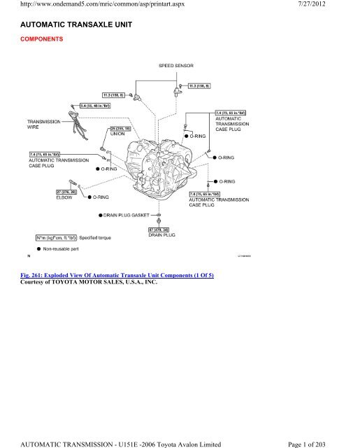
http://www.ondemand5.com/mric/common/asp/printart.aspx AUTOMATIC TRANSAXLE UNIT COMPONENTS Fig. 261: Exploded View Of Automatic Transaxle Unit Components (1 Of 5) Courtesy of TOYOTA MOTOR SALES, U.S.A., INC. AUTOMATIC TRANSMISSION - U151E -2006 Toyota Avalon Limited 7/27/2012 Page 1 of 203
- Page 2 and 3: http://www.ondemand5.com/mric/commo
- Page 4 and 5: http://www.ondemand5.com/mric/commo
- Page 6 and 7: http://www.ondemand5.com/mric/commo
- Page 8 and 9: http://www.ondemand5.com/mric/commo
- Page 10 and 11: http://www.ondemand5.com/mric/commo
- Page 12 and 13: http://www.ondemand5.com/mric/commo
- Page 14 and 15: http://www.ondemand5.com/mric/commo
- Page 16 and 17: http://www.ondemand5.com/mric/commo
- Page 18 and 19: http://www.ondemand5.com/mric/commo
- Page 20 and 21: http://www.ondemand5.com/mric/commo
- Page 22 and 23: http://www.ondemand5.com/mric/commo
- Page 24 and 25: http://www.ondemand5.com/mric/commo
- Page 26 and 27: http://www.ondemand5.com/mric/commo
- Page 28 and 29: http://www.ondemand5.com/mric/commo
- Page 30 and 31: http://www.ondemand5.com/mric/commo
- Page 32 and 33: http://www.ondemand5.com/mric/commo
- Page 34 and 35: http://www.ondemand5.com/mric/commo
- Page 36 and 37: http://www.ondemand5.com/mric/commo
- Page 38 and 39: http://www.ondemand5.com/mric/commo
- Page 40 and 41: http://www.ondemand5.com/mric/commo
- Page 42 and 43: http://www.ondemand5.com/mric/commo
- Page 44 and 45: http://www.ondemand5.com/mric/commo
- Page 46 and 47: http://www.ondemand5.com/mric/commo
- Page 48 and 49: http://www.ondemand5.com/mric/commo
- Page 50 and 51: http://www.ondemand5.com/mric/commo
http://www.ondemand5.com/mric/common/asp/printart.aspx<br />
<strong>AUTOMATIC</strong> <strong>TRANSAXLE</strong> <strong>UNIT</strong><br />
COMPONENTS<br />
Fig. 261: Exploded View Of Automatic Transaxle Unit Components (1 Of 5)<br />
Courtesy of TOYOTA MOTOR SALES, U.S.A., INC.<br />
<strong>AUTOMATIC</strong> TRANSMISSION - U151E -2006 Toyota Avalon Limited<br />
7/27/2012<br />
Page 1 of 203
http://www.ondemand5.com/mric/common/asp/printart.aspx<br />
Fig. 262: Exploded View Of Automatic Transaxle Unit Components (2 Of 5)<br />
Courtesy of TOYOTA MOTOR SALES, U.S.A., INC.<br />
<strong>AUTOMATIC</strong> TRANSMISSION - U151E -2006 Toyota Avalon Limited<br />
7/27/2012<br />
Page 2 of 203
http://www.ondemand5.com/mric/common/asp/printart.aspx<br />
Fig. 263: Exploded View Of Automatic Transaxle Unit Components (3 Of 5)<br />
Courtesy of TOYOTA MOTOR SALES, U.S.A., INC.<br />
<strong>AUTOMATIC</strong> TRANSMISSION - U151E -2006 Toyota Avalon Limited<br />
7/27/2012<br />
Page 3 of 203
http://www.ondemand5.com/mric/common/asp/printart.aspx<br />
Fig. 264: Exploded View Of Automatic Transaxle Unit Components (4 Of 5)<br />
Courtesy of TOYOTA MOTOR SALES, U.S.A., INC.<br />
<strong>AUTOMATIC</strong> TRANSMISSION - U151E -2006 Toyota Avalon Limited<br />
7/27/2012<br />
Page 4 of 203
http://www.ondemand5.com/mric/common/asp/printart.aspx<br />
Fig. 265: Exploded View Of Automatic Transaxle Unit Components (5 Of 5)<br />
Courtesy of TOYOTA MOTOR SALES, U.S.A., INC.<br />
DISASSEMBLY<br />
1. REMOVE PARK/NEUTRAL POSITION SWITCH ASSEMBLY<br />
a. Remove the nut, washer and control shaft lever.<br />
<strong>AUTOMATIC</strong> TRANSMISSION - U151E -2006 Toyota Avalon Limited<br />
7/27/2012<br />
Page 5 of 203
http://www.ondemand5.com/mric/common/asp/printart.aspx<br />
Fig. 266: Removing Nut And Control Shaft Lever<br />
Courtesy of TOYOTA MOTOR SALES, U.S.A., INC.<br />
b. Using a screwdriver, unstake the nut stopper, and remove the lock nut and nut stopper.<br />
Fig. 267: Removing Lock Nut And Nut Stopper<br />
Courtesy of TOYOTA MOTOR SALES, U.S.A., INC.<br />
<strong>AUTOMATIC</strong> TRANSMISSION - U151E -2006 Toyota Avalon Limited<br />
7/27/2012<br />
Page 6 of 203
http://www.ondemand5.com/mric/common/asp/printart.aspx<br />
c. Remove the 2 bolts and pull out the park/neutral position switch.<br />
2. REMOVE BREATHER PLUG HOSE<br />
a. Remove the breather plug hose from the transaxle case.<br />
Fig. 268: Removing 2 Bolts<br />
Courtesy of TOYOTA MOTOR SALES, U.S.A., INC.<br />
3. REMOVE OIL COOLER TUBE UNION (INLET OIL COOLER UNION)<br />
a. Remove the union.<br />
b. Remove the O-ring from the union.<br />
<strong>AUTOMATIC</strong> TRANSMISSION - U151E -2006 Toyota Avalon Limited<br />
7/27/2012<br />
Page 7 of 203
http://www.ondemand5.com/mric/common/asp/printart.aspx<br />
Fig. 269: Identifying Union And O-Ring<br />
Courtesy of TOYOTA MOTOR SALES, U.S.A., INC.<br />
4. REMOVE OIL COOLER TUBE UNION (OUTLET OIL COOLER UNION)<br />
a. Remove the elbow.<br />
b. Remove the O-ring from the elbow.<br />
<strong>AUTOMATIC</strong> TRANSMISSION - U151E -2006 Toyota Avalon Limited<br />
7/27/2012<br />
Page 8 of 203
http://www.ondemand5.com/mric/common/asp/printart.aspx<br />
Fig. 270: Identifying Elbow And O-Ring<br />
Courtesy of TOYOTA MOTOR SALES, U.S.A., INC.<br />
5. REMOVE SPEED SENSOR<br />
a. Remove the 2 bolts and the 2 speed sensors from the transaxle assembly.<br />
Fig. 271: Removing Speed Sensor<br />
Courtesy of TOYOTA MOTOR SALES, U.S.A., INC.<br />
6. REMOVE <strong>TRANSAXLE</strong> CASE NO. 1 PLUG<br />
a. Remove the 4 transaxle case No.1 plugs from the transaxle case.<br />
b. Remove the 4 O-rings from the 4 transaxle case No.1 plugs.<br />
<strong>AUTOMATIC</strong> TRANSMISSION - U151E -2006 Toyota Avalon Limited<br />
7/27/2012<br />
Page 9 of 203
http://www.ondemand5.com/mric/common/asp/printart.aspx<br />
Fig. 272: Locating 4 Transaxle Case No.1 Plugs To Transaxle Case<br />
Courtesy of TOYOTA MOTOR SALES, U.S.A., INC.<br />
7. FIX <strong>AUTOMATIC</strong> <strong>TRANSAXLE</strong> ASSEMBLY<br />
a. Fix the transaxle assembly.<br />
Fig. 273: View Of Oil Pan And 18 Bolts To Transaxle Case<br />
Courtesy of TOYOTA MOTOR SALES, U.S.A., INC.<br />
<strong>AUTOMATIC</strong> TRANSMISSION - U151E -2006 Toyota Avalon Limited<br />
7/27/2012<br />
Page 10 of 203
http://www.ondemand5.com/mric/common/asp/printart.aspx<br />
8. REMOVE <strong>AUTOMATIC</strong> <strong>TRANSAXLE</strong> OIL PAN SUB-ASSEMBLY<br />
a. Remove the 18 bolts, oil pan and gasket.<br />
Fig. 274: Identifying Oil Pan Bolts<br />
Courtesy of TOYOTA MOTOR SALES, U.S.A., INC.<br />
b. Remove the 2 magnets from the oil pan.<br />
<strong>AUTOMATIC</strong> TRANSMISSION - U151E -2006 Toyota Avalon Limited<br />
7/27/2012<br />
Page 11 of 203
http://www.ondemand5.com/mric/common/asp/printart.aspx<br />
Fig. 275: Removing 2 Magnets From Oil Pan<br />
Courtesy of TOYOTA MOTOR SALES, U.S.A., INC.<br />
9. INSPECT TRANSMISSION OIL CLEANER MAGNET<br />
a. Remove the magnets and use them to collect any steel chips. Examine the chips and particles in the pan and on the<br />
magnet to determine what type of wear has occurred in the transaxle:<br />
Result:<br />
Steel (magnetic):<br />
Wear of the bearing, gear and plate<br />
Brass (non-magnetic):<br />
Wear of the bushing<br />
<strong>AUTOMATIC</strong> TRANSMISSION - U151E -2006 Toyota Avalon Limited<br />
7/27/2012<br />
Page 12 of 203
http://www.ondemand5.com/mric/common/asp/printart.aspx<br />
Fig. 276: Collecting Steel Chips From Magnets<br />
Courtesy of TOYOTA MOTOR SALES, U.S.A., INC.<br />
10. DISCONNECT TRANSMISSION WIRE<br />
a. Remove the 7 connectors from the shift solenoid valves.<br />
b. Remove the bolt, lock plate and temperature sensor.<br />
<strong>AUTOMATIC</strong> TRANSMISSION - U151E -2006 Toyota Avalon Limited<br />
7/27/2012<br />
Page 13 of 203
http://www.ondemand5.com/mric/common/asp/printart.aspx<br />
Fig. 277: Disconnecting Transmission Wire<br />
Courtesy of TOYOTA MOTOR SALES, U.S.A., INC.<br />
11. REMOVE TRANSMISSION WIRE<br />
a. Remove the bolt and transmission wire from the transaxle case.<br />
Fig. 278: Removing Transmission Wire<br />
Courtesy of TOYOTA MOTOR SALES, U.S.A., INC.<br />
12. REMOVE VALVE BODY OIL STRAINER ASSEMBLY<br />
a. Remove the 3 bolts and oil strainer.<br />
<strong>AUTOMATIC</strong> TRANSMISSION - U151E -2006 Toyota Avalon Limited<br />
7/27/2012<br />
Page 14 of 203
http://www.ondemand5.com/mric/common/asp/printart.aspx<br />
Fig. 279: View Of Oil Strainer And Bolts<br />
Courtesy of TOYOTA MOTOR SALES, U.S.A., INC.<br />
b. Remove the O-ring from the oil strainer.<br />
<strong>AUTOMATIC</strong> TRANSMISSION - U151E -2006 Toyota Avalon Limited<br />
7/27/2012<br />
Page 15 of 203
http://www.ondemand5.com/mric/common/asp/printart.aspx<br />
Fig. 280: View Of O-Ring And Oil Strainer<br />
Courtesy of TOYOTA MOTOR SALES, U.S.A., INC.<br />
13. REMOVE TRANSMISSION VALVE BODY ASSEMBLY<br />
a. Support the valve body assembly and remove the 17 bolts and valve body assembly.<br />
<strong>AUTOMATIC</strong> TRANSMISSION - U151E -2006 Toyota Avalon Limited<br />
7/27/2012<br />
Page 16 of 203
http://www.ondemand5.com/mric/common/asp/printart.aspx<br />
Fig. 281: Locating 17 Bolts And Valve Body Assembly<br />
Courtesy of TOYOTA MOTOR SALES, U.S.A., INC.<br />
14. REMOVE GOVERNOR APPLY GASKET NO. 1<br />
a. Remove the governor apply gasket No.1 from the transaxle case.<br />
<strong>AUTOMATIC</strong> TRANSMISSION - U151E -2006 Toyota Avalon Limited<br />
7/27/2012<br />
Page 17 of 203
http://www.ondemand5.com/mric/common/asp/printart.aspx<br />
Fig. 282: Removing Governor Apply Gasket No.1<br />
Courtesy of TOYOTA MOTOR SALES, U.S.A., INC.<br />
15. REMOVE <strong>TRANSAXLE</strong> CASE 2ND BRAKE GASKET<br />
a. Remove the transaxle case 2nd brake gasket from the transaxle case.<br />
Fig. 283: Locating Transaxle Case 2nd Brake Gasket<br />
<strong>AUTOMATIC</strong> TRANSMISSION - U151E -2006 Toyota Avalon Limited<br />
7/27/2012<br />
Page 18 of 203
http://www.ondemand5.com/mric/common/asp/printart.aspx<br />
Courtesy of TOYOTA MOTOR SALES, U.S.A., INC.<br />
16. REMOVE BRAKE DRUM GASKET<br />
a. Remove the brake drum gasket from the transaxle case.<br />
Fig. 284: Identifying Brake Drum Gasket<br />
Courtesy of TOYOTA MOTOR SALES, U.S.A., INC.<br />
17. REMOVE CHECK BALL BODY<br />
a. Remove the check ball body and spring from the transaxle case.<br />
<strong>AUTOMATIC</strong> TRANSMISSION - U151E -2006 Toyota Avalon Limited<br />
7/27/2012<br />
Page 19 of 203
http://www.ondemand5.com/mric/common/asp/printart.aspx<br />
Fig. 285: View Of Check Ball, Body And Spring<br />
Courtesy of TOYOTA MOTOR SALES, U.S.A., INC.<br />
18. REMOVE C-3 ACCUMULATOR PISTON<br />
a. Remove the spring from the C-3 accumulator piston.<br />
<strong>AUTOMATIC</strong> TRANSMISSION - U151E -2006 Toyota Avalon Limited<br />
7/27/2012<br />
Page 20 of 203
http://www.ondemand5.com/mric/common/asp/printart.aspx<br />
Fig. 286: Identifying C3 Accumulator Piston Spring<br />
Courtesy of TOYOTA MOTOR SALES, U.S.A., INC.<br />
b. Apply compressed air (392 kPa, 4.0 kgf/cm 2 , 57 psi) to the oil hole and remove the C-3 accumulator piston.<br />
<strong>AUTOMATIC</strong> TRANSMISSION - U151E -2006 Toyota Avalon Limited<br />
7/27/2012<br />
Page 21 of 203
http://www.ondemand5.com/mric/common/asp/printart.aspx<br />
Fig. 287: Applying Compressed Air To Oil Hole<br />
Courtesy of TOYOTA MOTOR SALES, U.S.A., INC.<br />
NOTE: Applying compressed air may cause the piston to jump-out. When removing<br />
the piston, hold it using a waste cloth.<br />
Take care not to splash ATF when applying compressed air.<br />
c. Remove the O-ring from the C-3 accumulator piston.<br />
<strong>AUTOMATIC</strong> TRANSMISSION - U151E -2006 Toyota Avalon Limited<br />
7/27/2012<br />
Page 22 of 203
http://www.ondemand5.com/mric/common/asp/printart.aspx<br />
Fig. 288: Identifying C-3 Accumulator Piston And O-Ring<br />
Courtesy of TOYOTA MOTOR SALES, U.S.A., INC.<br />
7/27/2012<br />
19. REMOVE REVERSE CLUTCH ACCUMULATOR PISTON<br />
a. Apply compressed air (392 kPa, 4.0 kgf/cm2 , 57 psi) to the oil hole and remove the reverse accumulator piston<br />
and spring.<br />
NOTE: Applying compressed air may cause the piston to jump-out. When removing the<br />
piston, hold it using a waste cloth.<br />
Take care not to splash ATF when applying compressed air.<br />
<strong>AUTOMATIC</strong> TRANSMISSION - U151E -2006 Toyota Avalon Limited<br />
Page 23 of 203
http://www.ondemand5.com/mric/common/asp/printart.aspx<br />
Fig. 289: Removing Reverse Clutch Accumulator Piston<br />
Courtesy of TOYOTA MOTOR SALES, U.S.A., INC.<br />
b. Remove the 2 O-rings from the reverse clutch accumulator piston.<br />
Fig. 290: Removing O-Rings From Reverse Clutch Accumulator Piston<br />
Courtesy of TOYOTA MOTOR SALES, U.S.A., INC.<br />
<strong>AUTOMATIC</strong> TRANSMISSION - U151E -2006 Toyota Avalon Limited<br />
7/27/2012<br />
Page 24 of 203
http://www.ondemand5.com/mric/common/asp/printart.aspx<br />
20. REMOVE B-3 ACCUMULATOR PISTON<br />
a. Apply compressed air (392 kPa, 4.0 kgf/cm2 , 57 psi) to the oil hole and remove the B-3 accumulator piston and 2<br />
springs.<br />
NOTE: Applying compressed air may cause the piston to jump-out. When removing the<br />
piston, hold it using a waste cloth.<br />
Take care not to splash ATF when applying compressed air.<br />
Fig. 291: Removing B-3 Accumulator Piston<br />
Courtesy of TOYOTA MOTOR SALES, U.S.A., INC.<br />
b. Remove the O-ring from the B-3 accumulator piston.<br />
<strong>AUTOMATIC</strong> TRANSMISSION - U151E -2006 Toyota Avalon Limited<br />
7/27/2012<br />
Page 25 of 203
http://www.ondemand5.com/mric/common/asp/printart.aspx<br />
Fig. 292: Identifying O-Ring And B-3 Accumulator Piston<br />
Courtesy of TOYOTA MOTOR SALES, U.S.A., INC.<br />
21. REMOVE MANUAL VALVE LEVER SHAFT RETAINER SPRING<br />
a. Using needle-nose pliers, remove the manual valve lever shaft retainer spring.<br />
Fig. 293: Identifying Manual Valve Lever Shaft Retainer Spring<br />
<strong>AUTOMATIC</strong> TRANSMISSION - U151E -2006 Toyota Avalon Limited<br />
7/27/2012<br />
Page 26 of 203
http://www.ondemand5.com/mric/common/asp/printart.aspx<br />
Courtesy of TOYOTA MOTOR SALES, U.S.A., INC.<br />
22. REMOVE MANUAL DETENT SPRING SUB-ASSEMBLY<br />
a. Remove the 2 bolts, the manual detent spring sub-assembly and cover.<br />
Fig. 294: Removing Manual Detent Spring Sub-Assembly<br />
Courtesy of TOYOTA MOTOR SALES, U.S.A., INC.<br />
23. REMOVE PARKING LOCK PAWL BRACKET<br />
a. Remove the 2 bolts and parking lock pawl bracket.<br />
<strong>AUTOMATIC</strong> TRANSMISSION - U151E -2006 Toyota Avalon Limited<br />
7/27/2012<br />
Page 27 of 203
http://www.ondemand5.com/mric/common/asp/printart.aspx<br />
Fig. 295: Removing Parking Lock Pawl Bracket<br />
Courtesy of TOYOTA MOTOR SALES, U.S.A., INC.<br />
24. REMOVE MANUAL VALVE LEVER SUB-ASSEMBLY<br />
a. Using a chisel and hammer, cut off and remove the spacer.<br />
<strong>AUTOMATIC</strong> TRANSMISSION - U151E -2006 Toyota Avalon Limited<br />
7/27/2012<br />
Page 28 of 203
http://www.ondemand5.com/mric/common/asp/printart.aspx<br />
Fig. 296: Removing Spacer<br />
Courtesy of TOYOTA MOTOR SALES, U.S.A., INC.<br />
b. Using a pin punch (diameter 35 mm) and hammer, drive out the pin.<br />
HINT:<br />
Slowly drive out the pin so that it will not fall into the transaxle case.<br />
Fig. 297: Removing/Installing Drive Pin<br />
Courtesy of TOYOTA MOTOR SALES, U.S.A., INC.<br />
c. Remove the manual valve lever shaft and manual valve lever.<br />
<strong>AUTOMATIC</strong> TRANSMISSION - U151E -2006 Toyota Avalon Limited<br />
7/27/2012<br />
Page 29 of 203
http://www.ondemand5.com/mric/common/asp/printart.aspx<br />
Fig. 298: Identifying Manual Valve Lever Shaft<br />
Courtesy of TOYOTA MOTOR SALES, U.S.A., INC.<br />
25. REMOVE PARKING LOCK ROD SUB-ASSEMBLY<br />
a. Remove the parking lock rod from the manual valve lever.<br />
<strong>AUTOMATIC</strong> TRANSMISSION - U151E -2006 Toyota Avalon Limited<br />
7/27/2012<br />
Page 30 of 203
http://www.ondemand5.com/mric/common/asp/printart.aspx<br />
Fig. 299: Identifying Parking Lock Rod Sub-Assembly<br />
Courtesy of TOYOTA MOTOR SALES, U.S.A., INC.<br />
26. REMOVE MANUAL VALVE LEVER SHAFT OIL SEAL<br />
a. Using a screwdriver, remove the oil seal from the transaxle case.<br />
NOTE: Do not apply excessive force when removing the oil seal.<br />
27. FIX <strong>AUTOMATIC</strong> <strong>TRANSAXLE</strong> ASSEMBLY<br />
a. Fix the transaxle case with the oil pump side facing up.<br />
<strong>AUTOMATIC</strong> TRANSMISSION - U151E -2006 Toyota Avalon Limited<br />
7/27/2012<br />
Page 31 of 203
http://www.ondemand5.com/mric/common/asp/printart.aspx<br />
Fig. 300: Removing Manual Valve Lever Shaft Oil Seal<br />
Courtesy of TOYOTA MOTOR SALES, U.S.A., INC.<br />
28. INSPECT INPUT SHAFT ENDPLAY<br />
HINT:<br />
(See INSPECTION)<br />
29. REMOVE <strong>TRANSAXLE</strong> HOUSING<br />
a. Remove the 16 bolts.<br />
b. Tap on the circumference of the transaxle housing with a plastic hammer to remove the transaxle housing from the<br />
transaxle case.<br />
NOTE: The differential may be accidentally removed when the transaxle housing is<br />
removed.<br />
<strong>AUTOMATIC</strong> TRANSMISSION - U151E -2006 Toyota Avalon Limited<br />
7/27/2012<br />
Page 32 of 203
http://www.ondemand5.com/mric/common/asp/printart.aspx<br />
Fig. 301: Removing 16 Bolts<br />
Courtesy of TOYOTA MOTOR SALES, U.S.A., INC.<br />
30. REMOVE OIL PUMP ASSEMBLY<br />
a. Remove the 7 bolts and oil pump from the transaxle case.<br />
<strong>AUTOMATIC</strong> TRANSMISSION - U151E -2006 Toyota Avalon Limited<br />
7/27/2012<br />
Page 33 of 203
http://www.ondemand5.com/mric/common/asp/printart.aspx<br />
Fig. 302: Removing Oil Pump Assembly<br />
Courtesy of TOYOTA MOTOR SALES, U.S.A., INC.<br />
31. REMOVE THRUST NEEDLE ROLLER BEARING<br />
a. Remove the thrust needle roller bearing from the underdrive planetary gear assembly.<br />
Fig. 303: Identifying Thrust Needle Roller Bearing, Differential Gear Assembly And Forward Clutch<br />
Assembly<br />
Courtesy of TOYOTA MOTOR SALES, U.S.A., INC.<br />
32. REMOVE THRUST BEARING UNDERDRIVE RACE NO. 2<br />
a. Remove the thrust bearing underdrive race No.2 from the underdrive planetary gear assembly.<br />
<strong>AUTOMATIC</strong> TRANSMISSION - U151E -2006 Toyota Avalon Limited<br />
7/27/2012<br />
Page 34 of 203
http://www.ondemand5.com/mric/common/asp/printart.aspx<br />
Fig. 304: Identifying Thrust Bearing Underdrive Race No. 2, Differential Gear Assembly And Forward<br />
Clutch Assembly<br />
Courtesy of TOYOTA MOTOR SALES, U.S.A., INC.<br />
33. REMOVE DIFFERENTIAL GEAR ASSEMBLY<br />
a. Remove the differential gear assembly from the transaxle case.<br />
<strong>AUTOMATIC</strong> TRANSMISSION - U151E -2006 Toyota Avalon Limited<br />
7/27/2012<br />
Page 35 of 203
http://www.ondemand5.com/mric/common/asp/printart.aspx<br />
Fig. 305: View Of Differential Gear Assembly<br />
Courtesy of TOYOTA MOTOR SALES, U.S.A., INC.<br />
34. REMOVE OVERDRIVE BRAKE GASKET<br />
a. Remove the 2 overdrive brake gaskets from the transaxle case.<br />
Fig. 306: Identifying 2 O/D Brake Gaskets<br />
Courtesy of TOYOTA MOTOR SALES, U.S.A., INC.<br />
35. REMOVE FORWARD CLUTCH ASSEMBLY<br />
a. Remove the forward clutch assembly from the transaxle case.<br />
<strong>AUTOMATIC</strong> TRANSMISSION - U151E -2006 Toyota Avalon Limited<br />
7/27/2012<br />
Page 36 of 203
http://www.ondemand5.com/mric/common/asp/printart.aspx<br />
Fig. 307: View Of Forward Clutch Assembly<br />
Courtesy of TOYOTA MOTOR SALES, U.S.A., INC.<br />
b. Remove the thrust needle roller bearing from the forward clutch.<br />
<strong>AUTOMATIC</strong> TRANSMISSION - U151E -2006 Toyota Avalon Limited<br />
7/27/2012<br />
Page 37 of 203
http://www.ondemand5.com/mric/common/asp/printart.aspx<br />
Fig. 308: Removing Thrust Needle Roller Bearing<br />
Courtesy of TOYOTA MOTOR SALES, U.S.A., INC.<br />
36. REMOVE MULTIPLE DISC CLUTCH HUB<br />
a. Remove the thrust needle roller bearing, multiple disc clutch hub, thrust needle roller bearing and thrust bearing<br />
race No.1 from the transaxle case.<br />
37. INSPECT MULTIPLE DISC CLUTCH CLUTCH HUB<br />
HINT:<br />
(See INSPECTION)<br />
<strong>AUTOMATIC</strong> TRANSMISSION - U151E -2006 Toyota Avalon Limited<br />
7/27/2012<br />
Page 38 of 203
http://www.ondemand5.com/mric/common/asp/printart.aspx<br />
Fig. 309: Removing Multiple Disc Clutch Hub<br />
Courtesy of TOYOTA MOTOR SALES, U.S.A., INC.<br />
38. REMOVE UNDERDRIVE PLANETARY GEAR ASSEMBLY<br />
a. Remove the bolt and pawl shaft clamp.<br />
<strong>AUTOMATIC</strong> TRANSMISSION - U151E -2006 Toyota Avalon Limited<br />
7/27/2012<br />
Page 39 of 203
http://www.ondemand5.com/mric/common/asp/printart.aspx<br />
Fig. 310: View Of Pawl Shaft Clamp<br />
Courtesy of TOYOTA MOTOR SALES, U.S.A., INC.<br />
b. Remove the parking lock pawl shaft.<br />
Fig. 311: Removing Parking Lock Pawl Shaft<br />
Courtesy of TOYOTA MOTOR SALES, U.S.A., INC.<br />
c. Push the parking lock pawl.<br />
HINT:<br />
Failure to do so will cause interference when the underdrive planetary gear is removed.<br />
<strong>AUTOMATIC</strong> TRANSMISSION - U151E -2006 Toyota Avalon Limited<br />
7/27/2012<br />
Page 40 of 203
http://www.ondemand5.com/mric/common/asp/printart.aspx<br />
Fig. 312: Pushing Parking Lock Pawl<br />
Courtesy of TOYOTA MOTOR SALES, U.S.A., INC.<br />
d. Remove the underdrive planetary gear assembly from the transaxle case.<br />
NOTE: Be careful so that the underdrive planetary gear assembly will not fall out.<br />
<strong>AUTOMATIC</strong> TRANSMISSION - U151E -2006 Toyota Avalon Limited<br />
7/27/2012<br />
Page 41 of 203
http://www.ondemand5.com/mric/common/asp/printart.aspx<br />
Fig. 313: Identifying Underdrive Planetary Gear Assembly<br />
Courtesy of TOYOTA MOTOR SALES, U.S.A., INC.<br />
39. REMOVE PARKING LOCK PAWL<br />
a. Remove the spring, pawl pin and parking lock pawl.<br />
<strong>AUTOMATIC</strong> TRANSMISSION - U151E -2006 Toyota Avalon Limited<br />
7/27/2012<br />
Page 42 of 203
http://www.ondemand5.com/mric/common/asp/printart.aspx<br />
Fig. 314: Identifying Parking Lock Pawl, Shaft And Spring To Transaxle Case<br />
Courtesy of TOYOTA MOTOR SALES, U.S.A., INC.<br />
40. REMOVE UNDERDRIVE CLUTCH ASSEMBLY<br />
a. Remove the underdrive clutch assembly, thrust bearing and bearing race from the transaxle case.<br />
Fig. 315: Removing Thrust Bearing And Bearing Race<br />
Courtesy of TOYOTA MOTOR SALES, U.S.A., INC.<br />
41. REMOVE UNDERDRIVE 1-WAY CLUTCH ASSEMBLY<br />
a. Using a screwdriver, remove the snap ring from the transaxle case.<br />
NOTE: Do not apply excessive force when removing the snap ring.<br />
<strong>AUTOMATIC</strong> TRANSMISSION - U151E -2006 Toyota Avalon Limited<br />
7/27/2012<br />
Page 43 of 203
http://www.ondemand5.com/mric/common/asp/printart.aspx<br />
Fig. 316: Removing/Installing Snap Ring<br />
Courtesy of TOYOTA MOTOR SALES, U.S.A., INC.<br />
b. Remove the underdrive 1-way clutch from the transaxle case.<br />
<strong>AUTOMATIC</strong> TRANSMISSION - U151E -2006 Toyota Avalon Limited<br />
7/27/2012<br />
Page 44 of 203
http://www.ondemand5.com/mric/common/asp/printart.aspx<br />
Fig. 317: Removing Underdrive 1-Way Clutch<br />
Courtesy of TOYOTA MOTOR SALES, U.S.A., INC.<br />
c. Remove the outer race retainer from the 1-way clutch.<br />
Fig. 318: View Of 1-Way Clutch Outer Race Retainer<br />
Courtesy of TOYOTA MOTOR SALES, U.S.A., INC.<br />
42. REMOVE UNDERDRIVE CLUTCH DISC NO. 2<br />
a. Using a screwdriver, remove the snap ring.<br />
NOTE: Do not apply excessive force when removing the snap ring.<br />
<strong>AUTOMATIC</strong> TRANSMISSION - U151E -2006 Toyota Avalon Limited<br />
7/27/2012<br />
Page 45 of 203
http://www.ondemand5.com/mric/common/asp/printart.aspx<br />
Fig. 319: Removing Snap Ring<br />
Courtesy of TOYOTA MOTOR SALES, U.S.A., INC.<br />
b. Remove the flange, 4 discs and 4 plates from the transaxle case.<br />
43. INSPECT UNDERDRIVE CLUTCH DISC NO. 2<br />
HINT:<br />
(See INSPECTION)<br />
<strong>AUTOMATIC</strong> TRANSMISSION - U151E -2006 Toyota Avalon Limited<br />
7/27/2012<br />
Page 46 of 203
http://www.ondemand5.com/mric/common/asp/printart.aspx<br />
Fig. 320: Removing Flange<br />
Courtesy of TOYOTA MOTOR SALES, U.S.A., INC.<br />
44. REMOVE <strong>TRANSAXLE</strong> REAR COVER SUB-ASSEMBLY<br />
a. Remove the 11 bolts.<br />
b. Tap on the circumference of the rear cover with a plastic hammer to remove the transaxle rear cover from the<br />
transaxle case.<br />
<strong>AUTOMATIC</strong> TRANSMISSION - U151E -2006 Toyota Avalon Limited<br />
7/27/2012<br />
Page 47 of 203
http://www.ondemand5.com/mric/common/asp/printart.aspx<br />
Fig. 321: Removing 11 Bolts<br />
Courtesy of TOYOTA MOTOR SALES, U.S.A., INC.<br />
45. REMOVE <strong>TRANSAXLE</strong> CASE NO. 1 PLUG<br />
a. Remove the 4 transaxle case No.1 plugs from the transaxle rear cover.<br />
b. Remove the 4 O-rings from the 4 transaxle case No.1 plugs.<br />
Fig. 322: Identifying Transaxle Case No. 1 Plugs At Transaxle Rear Cover<br />
Courtesy of TOYOTA MOTOR SALES, U.S.A., INC.<br />
46. REMOVE REAR CLUTCH OIL SEAL RING OUTER<br />
a. Remove the 3 rear clutch oil seal rings from the transaxle rear cover.<br />
<strong>AUTOMATIC</strong> TRANSMISSION - U151E -2006 Toyota Avalon Limited<br />
7/27/2012<br />
Page 48 of 203
http://www.ondemand5.com/mric/common/asp/printart.aspx<br />
Fig. 323: Identifying 3 Rear Clutch Oil Seal Rings At Transaxle Rear Cover<br />
Courtesy of TOYOTA MOTOR SALES, U.S.A., INC.<br />
47. REMOVE NEEDLE-ROLLER BEARING<br />
a. Using SST, remove the needle-roller bearing from the transaxle rear cover.<br />
SST 09387-00041 (09387-01021, 09387-01030, 09387-01040)<br />
<strong>AUTOMATIC</strong> TRANSMISSION - U151E -2006 Toyota Avalon Limited<br />
7/27/2012<br />
Page 49 of 203
http://www.ondemand5.com/mric/common/asp/printart.aspx<br />
Fig. 324: Removing Needle-Roller Bearing<br />
Courtesy of TOYOTA MOTOR SALES, U.S.A., INC.<br />
48. REMOVE GOVERNOR APPLY GASKET NO. 1<br />
a. Using a screwdriver, remove the 3 apply gaskets.<br />
<strong>AUTOMATIC</strong> TRANSMISSION - U151E -2006 Toyota Avalon Limited<br />
7/27/2012<br />
Page 50 of 203
http://www.ondemand5.com/mric/common/asp/printart.aspx<br />
Fig. 325: Identifying Governor Apply Gaskets<br />
Courtesy of TOYOTA MOTOR SALES, U.S.A., INC.<br />
49. REMOVE BRAKE APPLY TUBE<br />
a. Remove the bolt, clamp and brake apply tube.<br />
b. Remove the clutch apply tube.<br />
c. Remove the brake apply tube from the clamp.<br />
NOTE: Do not bend the tubes.<br />
Fig. 326: Identifying Brake Apply And Clutch Apply Tubes<br />
Courtesy of TOYOTA MOTOR SALES, U.S.A., INC.<br />
50. REMOVE DIRECT CLUTCH ASSEMBLY<br />
a. Remove the thrust bearing and the direct clutch assembly from the transaxle case.<br />
<strong>AUTOMATIC</strong> TRANSMISSION - U151E -2006 Toyota Avalon Limited<br />
7/27/2012<br />
Page 51 of 203
http://www.ondemand5.com/mric/common/asp/printart.aspx<br />
Fig. 327: Identifying Thrust Bearing And Direct Clutch Assembly<br />
Courtesy of TOYOTA MOTOR SALES, U.S.A., INC.<br />
51. REMOVE OVERDRIVE DIRECT CLUTCH HUB SUB-ASSEMBLY<br />
a. Remove the thrust bearing race, thrust bearing and overdrive direct clutch hub from the planetary gear assembly.<br />
52. INSPECT OVERDRIVE DIRECT CLUTCH DRUM SUB-ASSEMBLY<br />
HINT:<br />
(See INSPECTION)<br />
<strong>AUTOMATIC</strong> TRANSMISSION - U151E -2006 Toyota Avalon Limited<br />
7/27/2012<br />
Page 52 of 203
http://www.ondemand5.com/mric/common/asp/printart.aspx<br />
Fig. 328: Removing Overdrive Direct Clutch Hub Sub-Assembly<br />
Courtesy of TOYOTA MOTOR SALES, U.S.A., INC.<br />
53. REMOVE REAR PLANETARY SUN GEAR ASSEMBLY<br />
a. Remove the rear planetary sun gear assembly from the transaxle case.<br />
<strong>AUTOMATIC</strong> TRANSMISSION - U151E -2006 Toyota Avalon Limited<br />
7/27/2012<br />
Page 53 of 203
http://www.ondemand5.com/mric/common/asp/printart.aspx<br />
Fig. 329: Identifying Rear Planetary Sun Gear Assembly<br />
Courtesy of TOYOTA MOTOR SALES, U.S.A., INC.<br />
b. Remove the thrust needle roller bearing and thrust bearing race from the rear planetary sun gear assembly.<br />
Fig. 330: Removing Thrust Needle Roller Bearing And Thrust Bearing Race<br />
Courtesy of TOYOTA MOTOR SALES, U.S.A., INC.<br />
c. Remove the planetary carrier thrust washer No.2 from the rear planetary sun gear assembly.<br />
<strong>AUTOMATIC</strong> TRANSMISSION - U151E -2006 Toyota Avalon Limited<br />
7/27/2012<br />
Page 54 of 203
http://www.ondemand5.com/mric/common/asp/printart.aspx<br />
Fig. 331: View Of Planetary Carrier Thrust Washer No. 2 And Rear Planetary Sun Gear<br />
Courtesy of TOYOTA MOTOR SALES, U.S.A., INC.<br />
54. REMOVE 1-WAY CLUTCH ASSEMBLY<br />
a. Remove the 1-way clutch assembly and the thrust needle roller bearing from the transaxle case.<br />
Fig. 332: Removing 1-Way Clutch Assembly And Thrust Needle Roller Bearing<br />
<strong>AUTOMATIC</strong> TRANSMISSION - U151E -2006 Toyota Avalon Limited<br />
7/27/2012<br />
Page 55 of 203
http://www.ondemand5.com/mric/common/asp/printart.aspx<br />
Courtesy of TOYOTA MOTOR SALES, U.S.A., INC.<br />
b. Remove the 1-way clutch inner race from the 1-way clutch assembly.<br />
Fig. 333: Identifying 1-Way Clutch Inner Race And 1-Way Clutch Assembly<br />
Courtesy of TOYOTA MOTOR SALES, U.S.A., INC.<br />
55. REMOVE 1-WAY CLUTCH SLEEVE OUTER<br />
a. Remove the 1-way clutch sleeve outer from the transaxle case.<br />
<strong>AUTOMATIC</strong> TRANSMISSION - U151E -2006 Toyota Avalon Limited<br />
7/27/2012<br />
Page 56 of 203
http://www.ondemand5.com/mric/common/asp/printart.aspx<br />
Fig. 334: Removing 1-Way Clutch Sleeve Outer<br />
Courtesy of TOYOTA MOTOR SALES, U.S.A., INC.<br />
56. REMOVE PLANETARY CARRIER THRUST WASHER NO. 1<br />
a. Remove the planetary carrier thrust washer No.1 from the planetary gear assembly.<br />
<strong>AUTOMATIC</strong> TRANSMISSION - U151E -2006 Toyota Avalon Limited<br />
7/27/2012<br />
Page 57 of 203
http://www.ondemand5.com/mric/common/asp/printart.aspx<br />
Fig. 335: Identifying Planetary Carrier Thrust Washer No 1<br />
Courtesy of TOYOTA MOTOR SALES, U.S.A., INC.<br />
57. REMOVE 2ND BRAKE CLUTCH DISC<br />
a. Using a screwdriver, remove the snap ring.<br />
Fig. 336: Removing Snap Ring<br />
Courtesy of TOYOTA MOTOR SALES, U.S.A., INC.<br />
b. Remove the flange, 4 discs and 4 plates from the transaxle case.<br />
58. INSPECT 2ND BRAKE CLUTCH DISC<br />
HINT:<br />
(See INSPECTION)<br />
59. REMOVE 2ND BRAKE PISTON ASSEMBLY<br />
a. Using a screwdriver, remove the snap ring.<br />
<strong>AUTOMATIC</strong> TRANSMISSION - U151E -2006 Toyota Avalon Limited<br />
7/27/2012<br />
Page 58 of 203
http://www.ondemand5.com/mric/common/asp/printart.aspx<br />
Fig. 337: Removing/Installing Snap Ring<br />
Courtesy of TOYOTA MOTOR SALES, U.S.A., INC.<br />
b. Remove the 2ND brake piston assembly from the transaxle case.<br />
<strong>AUTOMATIC</strong> TRANSMISSION - U151E -2006 Toyota Avalon Limited<br />
7/27/2012<br />
Page 59 of 203
http://www.ondemand5.com/mric/common/asp/printart.aspx<br />
Fig. 338: Removing 2Nd Brake Piston Assembly<br />
Courtesy of TOYOTA MOTOR SALES, U.S.A., INC.<br />
60. REMOVE REAR PLANETARY GEAR ASSEMBLY<br />
a. Using a screwdriver, remove the snap ring.<br />
Fig. 339: Removing/Installing Snap Ring<br />
Courtesy of TOYOTA MOTOR SALES, U.S.A., INC.<br />
b. Remove the rear planetary gear assembly from the transaxle case.<br />
<strong>AUTOMATIC</strong> TRANSMISSION - U151E -2006 Toyota Avalon Limited<br />
7/27/2012<br />
Page 60 of 203
http://www.ondemand5.com/mric/common/asp/printart.aspx<br />
Fig. 340: Identifying Rear Planetary Gear Assembly<br />
Courtesy of TOYOTA MOTOR SALES, U.S.A., INC.<br />
61. REMOVE INPUT SUN GEAR<br />
a. Remove the 2 thrust needle roller bearings, thrust bearing race No.2 and the input sun gear from the transaxle case.<br />
Fig. 341: Removing Input Sun Gear<br />
<strong>AUTOMATIC</strong> TRANSMISSION - U151E -2006 Toyota Avalon Limited<br />
7/27/2012<br />
Page 61 of 203
http://www.ondemand5.com/mric/common/asp/printart.aspx<br />
Courtesy of TOYOTA MOTOR SALES, U.S.A., INC.<br />
62. REMOVE 1ST AND REVERSE BRAKE CLUTCH DISC<br />
a. Remove the flange, 6 discs and 6 plates from the transaxle case.<br />
63. INSPECT 1ST AND REVERSE BRAKE CLUTCH DISC<br />
HINT:<br />
(See INSPECTION)<br />
Fig. 342: Removing Flange, 6 Discs And 6 Plates From Transaxle Case<br />
Courtesy of TOYOTA MOTOR SALES, U.S.A., INC.<br />
64. REMOVE FRONT PLANETARY GEAR ASSEMBLY<br />
a. Using a chisel and hammer, unstake the lock washer.<br />
7/27/2012<br />
NOTE: Push down all claws of the washer. Otherwise the SST cannot be fully pressed<br />
against the nut, and cannot loosen the nut.<br />
<strong>AUTOMATIC</strong> TRANSMISSION - U151E -2006 Toyota Avalon Limited<br />
Page 62 of 203
http://www.ondemand5.com/mric/common/asp/printart.aspx<br />
Fig. 343: Unstaking Lock Washer<br />
Courtesy of TOYOTA MOTOR SALES, U.S.A., INC.<br />
b. Using SST, remove the nut.<br />
SST 09387-00030, 09387-00080<br />
<strong>AUTOMATIC</strong> TRANSMISSION - U151E -2006 Toyota Avalon Limited<br />
7/27/2012<br />
Page 63 of 203
http://www.ondemand5.com/mric/common/asp/printart.aspx<br />
Fig. 344: Removing/Installing Front Planetary Gear Nut<br />
Courtesy of TOYOTA MOTOR SALES, U.S.A., INC.<br />
c. Using SST and a press, remove the front planetary gear assembly from the counter drive gear.<br />
SST 09950-60010 (09951-00450), 09950-70010 (09951-07100)<br />
Fig. 345: Removing Front Planetary Gear Assembly From Counter Drive Gear<br />
<strong>AUTOMATIC</strong> TRANSMISSION - U151E -2006 Toyota Avalon Limited<br />
7/27/2012<br />
Page 64 of 203
http://www.ondemand5.com/mric/common/asp/printart.aspx<br />
Courtesy of TOYOTA MOTOR SALES, U.S.A., INC.<br />
d. Remove the front planetary gear assembly from the brake hub.<br />
Fig. 346: View Of Front Planetary Gear Assembly And Brake Hub<br />
Courtesy of TOYOTA MOTOR SALES, U.S.A., INC.<br />
65. REMOVE FRONT PLANETARY RING GEAR<br />
a. Using a screwdriver, remove the snap ring and front planetary ring gear from the brake hub.<br />
<strong>AUTOMATIC</strong> TRANSMISSION - U151E -2006 Toyota Avalon Limited<br />
7/27/2012<br />
Page 65 of 203
http://www.ondemand5.com/mric/common/asp/printart.aspx<br />
Fig. 347: View Of Front Planetary Ring Gear, Snap Ring And Brake Hub<br />
Courtesy of TOYOTA MOTOR SALES, U.S.A., INC.<br />
66. REMOVE 1ST AND REVERSE BRAKE RETURN SPRING SUB-ASSEMBLY<br />
a. Place SST on the return spring, and compress the return spring with a press.<br />
SST 09387-00070<br />
b. Using a snap ring expander, remove the snap ring.<br />
7/27/2012<br />
NOTE: Stop the press when the spring seat is lowered 1 to 2 mm (0.039 to 0.078 in.) from<br />
the snap ring groove, to prevent the spring seat from being deformed.<br />
Do not expand the snap ring excessively.<br />
<strong>AUTOMATIC</strong> TRANSMISSION - U151E -2006 Toyota Avalon Limited<br />
Page 66 of 203
http://www.ondemand5.com/mric/common/asp/printart.aspx<br />
67. INSPECT 1ST AND REVERSE BRAKE RETURN SPRING SUB-ASSEMBLY<br />
HINT:<br />
(See INSPECTION)<br />
Fig. 348: Compressing Return Spring Using SST<br />
Courtesy of TOYOTA MOTOR SALES, U.S.A., INC.<br />
7/27/2012<br />
68. REMOVE 1ST AND REVERSE BRAKE PISTON<br />
a. Apply compressed air (392 kPa, 4.0 kgf/cm2 , 57 psi) to the transaxle case to remove the 1st and reverse brake<br />
piston.<br />
NOTE: Applying compressed air may cause the piston to jump-out. When removing the<br />
piston, hold it using a waste cloth.<br />
Take care not to splash ATF when applying compressed air.<br />
<strong>AUTOMATIC</strong> TRANSMISSION - U151E -2006 Toyota Avalon Limited<br />
Page 67 of 203
http://www.ondemand5.com/mric/common/asp/printart.aspx<br />
Fig. 349: Removing 1st And Reverse Brake Piston<br />
Courtesy of TOYOTA MOTOR SALES, U.S.A., INC.<br />
b. Remove the 2 O-rings from the 1st and reverse brake piston.<br />
Fig. 350: Locating 2 O-Rings<br />
Courtesy of TOYOTA MOTOR SALES, U.S.A., INC.<br />
<strong>AUTOMATIC</strong> TRANSMISSION - U151E -2006 Toyota Avalon Limited<br />
7/27/2012<br />
Page 68 of 203
http://www.ondemand5.com/mric/common/asp/printart.aspx<br />
69. REMOVE COUNTER DRIVE GEAR<br />
a. Using SST and a press, remove the counter drive gear from the transaxle case.<br />
SST 09950-60010 (09951-00590), 09950-70010 (09951-07100)<br />
Fig. 351: Removing Counter Drive Gear<br />
Courtesy of TOYOTA MOTOR SALES, U.S.A., INC.<br />
7/27/2012<br />
b. As shown in Fig. 352, tighten the 2 bolts evenly and make clearance of approx. 20.0 mm (0.787 in.) between the<br />
counter drive gear and the inner race.<br />
<strong>AUTOMATIC</strong> TRANSMISSION - U151E -2006 Toyota Avalon Limited<br />
Page 69 of 203
http://www.ondemand5.com/mric/common/asp/printart.aspx<br />
Fig. 352: Tightening Bolts Evenly And Checking Clearance Between Counter Drive Gear And Inner Race<br />
Courtesy of TOYOTA MOTOR SALES, U.S.A., INC.<br />
c. Using SST, remove the tapered roller bearing.<br />
SST 09950-60010 (09951-00590), 09950-00020, 09950-00030, 09950-40011 (09957-04010)<br />
<strong>AUTOMATIC</strong> TRANSMISSION - U151E -2006 Toyota Avalon Limited<br />
7/27/2012<br />
Page 70 of 203
http://www.ondemand5.com/mric/common/asp/printart.aspx<br />
Fig. 353: Removing Tapered Roller Bearing Using SST<br />
Courtesy of TOYOTA MOTOR SALES, U.S.A., INC.<br />
70. REMOVE TRANSFER DRIVEN PINION FRONT BEARING<br />
a. Using a snap ring expander, remove the snap ring.<br />
Fig. 354: Removing/Installing Snap Ring<br />
Courtesy of TOYOTA MOTOR SALES, U.S.A., INC.<br />
b. Using SST and a press, remove the bearing outer race.<br />
SST 09950-60020 (09951-00910)<br />
71. REMOVE BREATHER PLUG NO. 2 (ATM)<br />
<strong>AUTOMATIC</strong> TRANSMISSION - U151E -2006 Toyota Avalon Limited<br />
7/27/2012<br />
Page 71 of 203
http://www.ondemand5.com/mric/common/asp/printart.aspx<br />
Fig. 355: Removing Bearing Outer Race<br />
Courtesy of TOYOTA MOTOR SALES, U.S.A., INC.<br />
72. REMOVE UNDERDRIVE BRAKE RETURN SPRING SUB-ASSEMBLY<br />
a. Place SST on the return spring, and compress the return spring with a press.<br />
SST 09387-00020<br />
b. Using a snap ring expander, remove the snap ring.<br />
7/27/2012<br />
NOTE: Stop the press when the spring seat is lowered 1 to 2 mm (0.039 to 0.078 in.) from<br />
the snap ring groove, to prevent the spring seat from being deformed.<br />
Do not expand the snap ring excessively.<br />
<strong>AUTOMATIC</strong> TRANSMISSION - U151E -2006 Toyota Avalon Limited<br />
Page 72 of 203
http://www.ondemand5.com/mric/common/asp/printart.aspx<br />
73. INSPECT UNDERDRIVE BRAKE RETURN SPRING SUB-ASSEMBLY<br />
HINT:<br />
(See INSPECTION)<br />
Fig. 356: View Of SST And Snap Ring<br />
Courtesy of TOYOTA MOTOR SALES, U.S.A., INC.<br />
7/27/2012<br />
74. REMOVE UNDERDRIVE BRAKE PISTON<br />
a. Apply compressed air (392 kPa, 4.0 kgf/cm2 , 57 psi) to the transaxle case to remove the underdrive brake piston.<br />
<strong>AUTOMATIC</strong> TRANSMISSION - U151E -2006 Toyota Avalon Limited<br />
Page 73 of 203
http://www.ondemand5.com/mric/common/asp/printart.aspx<br />
Fig. 357: Removing Underdrive Brake Piston<br />
Courtesy of TOYOTA MOTOR SALES, U.S.A., INC.<br />
b. Remove the 2 O-rings from the underdrive brake piston.<br />
<strong>AUTOMATIC</strong> TRANSMISSION - U151E -2006 Toyota Avalon Limited<br />
7/27/2012<br />
Page 74 of 203
http://www.ondemand5.com/mric/common/asp/printart.aspx<br />
Fig. 358: Locating Brake Piston O-Rings<br />
Courtesy of TOYOTA MOTOR SALES, U.S.A., INC.<br />
75. REMOVE NEEDLE ROLLER BEARING<br />
a. Using SST, remove the needleroller bearing from the transaxle case.<br />
SST 09387-00041 (09387-01010, 09387-01030, 09387-01040)<br />
<strong>AUTOMATIC</strong> TRANSMISSION - U151E -2006 Toyota Avalon Limited<br />
7/27/2012<br />
Page 75 of 203
http://www.ondemand5.com/mric/common/asp/printart.aspx<br />
Fig. 359: Removing Needle Roller Bearing<br />
Courtesy of TOYOTA MOTOR SALES, U.S.A., INC.<br />
76. REMOVE UNDERDRIVE CLUTCH DRUM OIL SEAL RING<br />
a. Remove the 2 oil seal rings from the transaxle case.<br />
<strong>AUTOMATIC</strong> TRANSMISSION - U151E -2006 Toyota Avalon Limited<br />
7/27/2012<br />
Page 76 of 203
http://www.ondemand5.com/mric/common/asp/printart.aspx<br />
Fig. 360: Removing Underdrive Clutch Drum Oil Seal Ring<br />
Courtesy of TOYOTA MOTOR SALES, U.S.A., INC.<br />
77. REMOVE <strong>TRANSAXLE</strong> CASE NO. 1 PLUG<br />
a. Remove the 2 transaxle case No.1 plugs.<br />
b. Remove the 2 O-rings from the 2 transaxle case No.1 plugs.<br />
Fig. 361: Identifying Transaxle Case No 1 Plugs<br />
<strong>AUTOMATIC</strong> TRANSMISSION - U151E -2006 Toyota Avalon Limited<br />
7/27/2012<br />
Page 77 of 203
http://www.ondemand5.com/mric/common/asp/printart.aspx<br />
Courtesy of TOYOTA MOTOR SALES, U.S.A., INC.<br />
78. REMOVE UNDERDRIVE CYLINDRICAL ROLLER BEARING<br />
a. Using SST, remove the underdrive cylindrical roller bearing from the transaxle case.<br />
SST 09514-35011<br />
Fig. 362: Removing Underdrive Cylindrical Roller Bearing<br />
Courtesy of TOYOTA MOTOR SALES, U.S.A., INC.<br />
79. REMOVE UNDERDRIVE OUTPUT SHAFT OIL SEAL RING<br />
a. Remove the oil seal ring from the transaxle housing.<br />
<strong>AUTOMATIC</strong> TRANSMISSION - U151E -2006 Toyota Avalon Limited<br />
7/27/2012<br />
Page 78 of 203
http://www.ondemand5.com/mric/common/asp/printart.aspx<br />
Fig. 363: Removing Underdrive Output Shaft Oil Seal Ring<br />
Courtesy of TOYOTA MOTOR SALES, U.S.A., INC.<br />
80. REMOVE DIFFERENTIAL GEAR LUBE APPLY TUBE<br />
a. Remove the bolt, transaxle apply tube clamp and differential gear lube apply tube from the transaxle housing.<br />
NOTE: Do not bend the tubes.<br />
<strong>AUTOMATIC</strong> TRANSMISSION - U151E -2006 Toyota Avalon Limited<br />
7/27/2012<br />
Page 79 of 203
http://www.ondemand5.com/mric/common/asp/printart.aspx<br />
INSPECTION<br />
Fig. 364: Removing Transaxle Apply Tube Clamp And Differential Gear Lube Apply Tube<br />
Courtesy of TOYOTA MOTOR SALES, U.S.A., INC.<br />
1. INSPECT MULTIPLE DISC CLUTCH HUB<br />
a. Using a dial indicator, measure the inside diameter of the forward clutch hub bushing<br />
<strong>AUTOMATIC</strong> TRANSMISSION - U151E -2006 Toyota Avalon Limited<br />
7/27/2012<br />
Page 80 of 203
http://www.ondemand5.com/mric/common/asp/printart.aspx<br />
Fig. 365: Measuring Inside Diameter Of Forward Clutch Hub Bushing<br />
Courtesy of TOYOTA MOTOR SALES, U.S.A., INC.<br />
Standard inside diameter:<br />
23.025 to 23.046 mm (0.9065 to 0.9073 in.)<br />
Maximum inside diameter:<br />
23.09 mm (0.9091 in.)<br />
NOTE: Check the contact surface of the bushing in the direct clutch shaft. If any scratch<br />
or discoloration is found, replace the direct clutch sub-assembly with a new one.<br />
If the inside diameter is greater than the maximum, replace the forward clutch hub with a new one.<br />
2. INSPECT UNDERDRIVE CLUTCH DISC NO. 2<br />
a. Check if the sliding surfaces of the disc, plate and flange are worn or burnt.<br />
If necessary, replace them.<br />
NOTE: If the lining of the disc comes off or discolors, or if a part of the groove is worn,<br />
replace all discs.<br />
Before installing new discs, immerse them in ATF for at least 15 minutes.<br />
Fig. 366: Identifying Underdrive Clutch Disc No.2<br />
Courtesy of TOYOTA MOTOR SALES, U.S.A., INC.<br />
3. INSPECT OVERDRIVE DIRECT CLUTCH DRUM SUB-ASSEMBLY<br />
a. Using a dial indicator, measure the inside diameter of the forward clutch hub bushing.<br />
<strong>AUTOMATIC</strong> TRANSMISSION - U151E -2006 Toyota Avalon Limited<br />
7/27/2012<br />
Page 81 of 203
http://www.ondemand5.com/mric/common/asp/printart.aspx<br />
Fig. 367: Measuring Inside Diameter Of Forward Clutch Hub Bushing<br />
Courtesy of TOYOTA MOTOR SALES, U.S.A., INC.<br />
Standard inside diameter:<br />
23.025 to 23.046 mm (0.9065 to 0.9073 in.)<br />
Maximum inside diameter:<br />
23.09 mm (0.9091 in.)<br />
NOTE: Check the contact surface of the bushing in the direct clutch shaft. If any scratch<br />
or discoloration is found, replace the direct clutch sub-assembly with a new one.<br />
If the inside diameter is greater than the maximum, replace the forward clutch hub with a new one.<br />
4. INSPECT 2ND BRAKE CLUTCH DISC<br />
a. Check if the sliding surface of the disc, plate and flange are worn or burnt.<br />
If necessary, replace them.<br />
7/27/2012<br />
NOTE: If the lining of the disc comes off or discolors, or if a part of the groove is worn,<br />
replace all discs.<br />
Before installing new discs, immerse them in ATF for at least 15 minutes.<br />
<strong>AUTOMATIC</strong> TRANSMISSION - U151E -2006 Toyota Avalon Limited<br />
Page 82 of 203
http://www.ondemand5.com/mric/common/asp/printart.aspx<br />
5. INSPECT 1ST AND REVERSE BRAKE CLUTCH DISC<br />
a. Check if the sliding surface of the disc, plate and flange are worn or burnt.<br />
If necessary, replace them.<br />
Fig. 368: Identifying 2nd Brake Clutch Disc<br />
Courtesy of TOYOTA MOTOR SALES, U.S.A., INC.<br />
7/27/2012<br />
NOTE: If the lining of the disc comes off or discolors, or if a part of the groove is worn,<br />
replace all discs.<br />
Before installing new discs, immerse them in ATF for at least 15 minutes.<br />
<strong>AUTOMATIC</strong> TRANSMISSION - U151E -2006 Toyota Avalon Limited<br />
Page 83 of 203
http://www.ondemand5.com/mric/common/asp/printart.aspx<br />
6. INSPECT 1ST AND REVERSE BRAKE RETURN SPRING SUB-ASSEMBLY<br />
a. Using a vernier calipers, measure the free length of the spring together with the spring seat.<br />
Standard free length:<br />
17.61 mm (0.6933 in.)<br />
HINT:<br />
Fig. 369: View Of Clutch Disc<br />
Courtesy of TOYOTA MOTOR SALES, U.S.A., INC.<br />
If the result is not as specified, replace the spring.<br />
<strong>AUTOMATIC</strong> TRANSMISSION - U151E -2006 Toyota Avalon Limited<br />
7/27/2012<br />
Page 84 of 203
http://www.ondemand5.com/mric/common/asp/printart.aspx<br />
Fig. 370: Measuring Free Length Of Spring<br />
Courtesy of TOYOTA MOTOR SALES, U.S.A., INC.<br />
7. INSPECT UNDERDRIVE BRAKE RETURN SPRING SUB-ASSEMBLY<br />
a. Using a vernier calipers, measure the free length of the spring together with the spring seat.<br />
Standard free length:<br />
13.24 mm (0.5213 in.)<br />
HINT:<br />
If the result is not as specified, replace the spring.<br />
<strong>AUTOMATIC</strong> TRANSMISSION - U151E -2006 Toyota Avalon Limited<br />
7/27/2012<br />
Page 85 of 203
http://www.ondemand5.com/mric/common/asp/printart.aspx<br />
Fig. 371: Measuring Free Length Of Spring (Underdrive Brake Return Spring)<br />
Courtesy of TOYOTA MOTOR SALES, U.S.A., INC.<br />
8. INSPECT PACK CLEARANCE OF 1ST AND REVERSE BRAKE<br />
a. Using vernier calipers, measure the distance between the disc surface and the contact surface of the 2nd brake<br />
cylinder and transaxle case (Dimension A).<br />
b. Select an appropriate flange so that the pack clearance will meet the specified value.<br />
Pack clearance:<br />
1.16 to 1.35 mm (0.0457 to 0.0531 in.)<br />
<strong>AUTOMATIC</strong> TRANSMISSION - U151E -2006 Toyota Avalon Limited<br />
7/27/2012<br />
Page 86 of 203
http://www.ondemand5.com/mric/common/asp/printart.aspx<br />
Fig. 372: Measuring (Dimension A)<br />
Courtesy of TOYOTA MOTOR SALES, U.S.A., INC.<br />
HINT:<br />
Piston stroke = Dimension A - Flange thickness<br />
Flange thickness: mm (in.)<br />
FLANGE THICKNESS SPECIFICATIONS<br />
Mark Thickness<br />
1 1.8 (0.071)<br />
2 1.9 (0.075)<br />
3 2.0 (0.079)<br />
4 2.1 (0.083)<br />
5 2.2 (0.087)<br />
6 2.3 (0.091)<br />
7 2.4 (0.094)<br />
8 2.5 (0.098)<br />
c. Install the flange.<br />
9. INSPECT PACK CLEARANCE OF 2ND BRAKE<br />
a. Using a vernier calipers, measure the distance between the disc surface and snap ring surface (Dimension B).<br />
b. Select an appropriate flange so that the pack clearance will meet the specified value.<br />
Pack clearance:<br />
0.62 to 0.91 mm (0.0244 to 0.0358 in.)<br />
HINT:<br />
<strong>AUTOMATIC</strong> TRANSMISSION - U151E -2006 Toyota Avalon Limited<br />
7/27/2012<br />
Page 87 of 203
http://www.ondemand5.com/mric/common/asp/printart.aspx<br />
Piston stroke = Dimension B - Flange thickness - Snap ring thickness 1.6 mm (0.063 in.)<br />
Flange thickness: mm (in.)<br />
FLANGE THICKNESS SPECIFICATIONS<br />
Mark Thickness<br />
1 3.0 (0.118)<br />
2 3.1 (0.122)<br />
3 3.2 (0.126)<br />
4 3.3 (0.130)<br />
5 3.4 (0.134)<br />
6 3.5 (0.138)<br />
7 3.6 (0.142)<br />
8 -<br />
Fig. 373: Measuring Dimension B<br />
Courtesy of TOYOTA MOTOR SALES, U.S.A., INC.<br />
10. INSPECT PACK CLEARANCE OF UNDERDRIVE BRAKE<br />
a. Using a dial indicator, measure the underdrive brake pack clearance while applying and releasing compressed air<br />
(392 kPa, 4.0 kgf/cm 2 , 57 psi).<br />
Pack clearance:<br />
1.81 to 2.20 mm (0.0713 to 0.0866 in.)<br />
HINT:<br />
Select an appropriate flange from the table below so that it will meet the specified value.<br />
Flange thickness: mm (in.)<br />
<strong>AUTOMATIC</strong> TRANSMISSION - U151E -2006 Toyota Avalon Limited<br />
7/27/2012<br />
Page 88 of 203
http://www.ondemand5.com/mric/common/asp/printart.aspx<br />
FLANGE THICKNESS SPECIFICATIONS<br />
Mark Thickness<br />
1 3.0 (0.118)<br />
2 3.2 (0.126)<br />
3 3.4 (0.134)<br />
4 3.1 (0.122)<br />
5 3.3 (0.130)<br />
- -<br />
Fig. 374: Measuring Underdrive Brake Pack Clearance<br />
Courtesy of TOYOTA MOTOR SALES, U.S.A., INC.<br />
b. Temporarily remove the snap ring and attach it to the flange.<br />
c. Reinstall the snap ring.<br />
11. INSPECT UNDERDRIVE 1-WAY CLUTCH ASSEMBLY<br />
a. Install the underdrive clutch assembly to the 1-way clutch.<br />
b. Rotate the underdrive 1-way clutch assembly to check the rotating direction for the lock or free operation.<br />
HINT:<br />
If the result is not as specified, replace the underdrive 1-way clutch.<br />
<strong>AUTOMATIC</strong> TRANSMISSION - U151E -2006 Toyota Avalon Limited<br />
7/27/2012<br />
Page 89 of 203
http://www.ondemand5.com/mric/common/asp/printart.aspx<br />
Fig. 375: Checking Underdrive Clutch Assembly Rotation<br />
Courtesy of TOYOTA MOTOR SALES, U.S.A., INC.<br />
12. INSPECT INPUT SHAFT END PLAY<br />
a. Using a dial indicator, measure the input shaft end play.<br />
End play:<br />
0.262 to 1.244 mm (0.01 to 0.049 in.)<br />
HINT:<br />
If the result is not as specified, replace the input shaft or thrust needle roller bearing.<br />
<strong>AUTOMATIC</strong> TRANSMISSION - U151E -2006 Toyota Avalon Limited<br />
7/27/2012<br />
Page 90 of 203
http://www.ondemand5.com/mric/common/asp/printart.aspx<br />
REASSEMBLY<br />
Fig. 376: Inspecting Input Shaft End Play<br />
Courtesy of TOYOTA MOTOR SALES, U.S.A., INC.<br />
1. BEARING POSITION<br />
<strong>AUTOMATIC</strong> TRANSMISSION - U151E -2006 Toyota Avalon Limited<br />
7/27/2012<br />
Page 91 of 203
http://www.ondemand5.com/mric/common/asp/printart.aspx<br />
Fig. 377: Identifying Bearing Position<br />
Courtesy of TOYOTA MOTOR SALES, U.S.A., INC.<br />
BEARING SPECIFICATIONS<br />
Mark<br />
Front Race Diameter<br />
Inside/Outside mm(in.)<br />
Thrust Bearing Diameter<br />
Inside/Outside mm(in.)<br />
Rear Race Diameter<br />
Inside/Outside mm(in.)<br />
A - 57.2(2.252)/84.96(3.3449) 56.4(2.220)/83.0(3.268)<br />
B - 37.73(1.4854)/58.0(2.283) -<br />
C - 33.85(1.3327)/52.2(2.055) -<br />
D 24.94(0.982) 23.5(0.925)/44.0(1.732) -<br />
E - 36.3(1.429)/51.93(2.044) 34.5(1.358)/48.35(1.904)<br />
F 34.35(1.352)/56.57(2.227) 32.45(1.278)/56.48(2.223) -<br />
G 40.15(1.581)/59.25(2.333) 38.65(1.522)/59.79(2.354) 38.65(1.522)/59.25(2.332)<br />
H - 53.6(2.110)/69.6(2.740) -<br />
I 33.02(1.3)/45.8(1.803) 31.85(1.254)/57.3(2.256) -<br />
<strong>AUTOMATIC</strong> TRANSMISSION - U151E -2006 Toyota Avalon Limited<br />
7/27/2012<br />
Page 92 of 203
http://www.ondemand5.com/mric/common/asp/printart.aspx<br />
J - 24.79(0.976)/39.5(1.555) 23.6(0.929)/37.95(1.494)<br />
K - 56.3(2.216)/75.96(2.991) -<br />
2. INSTALL DIFFERENTIAL GEAR LUBE APPLY TUBE<br />
a. Install the differential gear lube apply tube and transaxle apply tube clamp with the bolt to the transaxle housing.<br />
Torque: 9.8 N*m (100 kgf*cm, 87 in.*lbf)<br />
NOTE: Make sure to insert the pipe to the stopper.<br />
Fig. 378: Installing Differential Gear Lube Apply Tube And Transaxle Apply Tube Clamp<br />
Courtesy of TOYOTA MOTOR SALES, U.S.A., INC.<br />
3. INSTALL <strong>TRANSAXLE</strong> CASE NO. 1 PLUG<br />
a. Install 2 new O-rings to the 2 transaxle case No.1 plugs.<br />
b. Install the 2 transaxle case No.1 plugs to the transaxle rear cover.<br />
<strong>AUTOMATIC</strong> TRANSMISSION - U151E -2006 Toyota Avalon Limited<br />
7/27/2012<br />
Page 93 of 203
http://www.ondemand5.com/mric/common/asp/printart.aspx<br />
Torque: 7.4 N*m (75 kgf*cm, 65 in.*lbf)<br />
Fig. 379: Identifying Transaxle Case No 1 Plugs<br />
Courtesy of TOYOTA MOTOR SALES, U.S.A., INC.<br />
4. INSTALL UNDERDRIVE OUTPUT SHAFT OIL SEAL RING<br />
a. Coat a new oil seal ring with ATF and install it to the transaxle housing.<br />
<strong>AUTOMATIC</strong> TRANSMISSION - U151E -2006 Toyota Avalon Limited<br />
7/27/2012<br />
Page 94 of 203
http://www.ondemand5.com/mric/common/asp/printart.aspx<br />
Fig. 380: Installing Underdrive Output Shaft Oil Seal Ring<br />
Courtesy of TOYOTA MOTOR SALES, U.S.A., INC.<br />
5. INSTALL UNDERDRIVE CYLINDRICAL ROLLER BEARING<br />
a. Coat the underdrive cylindrical roller bearing with ATF.<br />
b. Using SST and a press, install the underdrive cylindrical roller bearing.<br />
SST 09950-60020 (09951-00810), 09950-70010 (09951-07100)<br />
NOTE: Do not apply excessive pressure to the bearing.<br />
<strong>AUTOMATIC</strong> TRANSMISSION - U151E -2006 Toyota Avalon Limited<br />
7/27/2012<br />
Page 95 of 203
http://www.ondemand5.com/mric/common/asp/printart.aspx<br />
Fig. 381: Pressing In Underdrive Cylindrical Roller Bearing<br />
Courtesy of TOYOTA MOTOR SALES, U.S.A., INC.<br />
6. INSTALL UNDERDRIVE CLUTCH DRUM OIL SEAL RING<br />
a. Coat 2 new oil seal rings with ATF, and install them to the transaxle rear cover.<br />
NOTE: Do not expand the end gap of the oil seal ring too much.<br />
Fix the hooks firmly. Confirm that the oil seal ring rotates freely in its groove.<br />
<strong>AUTOMATIC</strong> TRANSMISSION - U151E -2006 Toyota Avalon Limited<br />
7/27/2012<br />
Page 96 of 203
http://www.ondemand5.com/mric/common/asp/printart.aspx<br />
Fig. 382: Installing Underdrive Clutch Drum Oil Seal Ring<br />
Courtesy of TOYOTA MOTOR SALES, U.S.A., INC.<br />
7. INSTALL NEEDLE ROLLER BEARING<br />
a. Wrap vinyl tape around the SST 4.0 mm (0.157 in.) from the bottom of the SST until the thickness of the tape is<br />
about 5.0 mm (0.197 in.).<br />
SST 09950-60010 (09951-00320), 09950-70010 (09951-07100)<br />
NOTE: Clean SST to remove deposited oil, before wrapping vinyl tape.<br />
b. Coat the needle roller bearing with ATF.<br />
<strong>AUTOMATIC</strong> TRANSMISSION - U151E -2006 Toyota Avalon Limited<br />
7/27/2012<br />
Page 97 of 203
http://www.ondemand5.com/mric/common/asp/printart.aspx<br />
Fig. 383: Wrapping Vinyl Tape Around SST<br />
Courtesy of TOYOTA MOTOR SALES, U.S.A., INC.<br />
c. Using SST and a press, install the needle-roller bearing to the transaxle case.<br />
SST 09950-60010 (09951-00320), 09950-70010 (09951-07100)<br />
NOTE: When the wrapped vinyl tape contacts the transaxle case, stop press-fitting.<br />
<strong>AUTOMATIC</strong> TRANSMISSION - U151E -2006 Toyota Avalon Limited<br />
7/27/2012<br />
Page 98 of 203
http://www.ondemand5.com/mric/common/asp/printart.aspx<br />
Fig. 384: Pressing In Needle-Roller Bearing To Transaxle Case<br />
Courtesy of TOYOTA MOTOR SALES, U.S.A., INC.<br />
8. INSTALL UNDERDRIVE BRAKE PISTON<br />
a. Coat 2 new O-rings with ATF, and install them to the underdrive brake piston.<br />
NOTE: Make sure that the O-rings are not twisted or pinched when they are<br />
installed.<br />
Apply sufficient ATF to the O-ring before installing.<br />
b. Coat the underdrive brake piston with ATF.<br />
<strong>AUTOMATIC</strong> TRANSMISSION - U151E -2006 Toyota Avalon Limited<br />
7/27/2012<br />
Page 99 of 203
http://www.ondemand5.com/mric/common/asp/printart.aspx<br />
Fig. 385: Locating O-Rings<br />
Courtesy of TOYOTA MOTOR SALES, U.S.A., INC.<br />
c. Install the underdrive brake piston to the transaxle case.<br />
NOTE: Be careful not to damage the O-ring.<br />
<strong>AUTOMATIC</strong> TRANSMISSION - U151E -2006 Toyota Avalon Limited<br />
7/27/2012<br />
Page 100 of 203
http://www.ondemand5.com/mric/common/asp/printart.aspx<br />
Fig. 386: Installing Underdrive Brake Piston<br />
Courtesy of TOYOTA MOTOR SALES, U.S.A., INC.<br />
9. INSTALL UNDERDRIVE BRAKE RETURN SPRING SUB-ASSEMBLY<br />
a. Place SST on the return spring and compress the return spring with a press.<br />
SST 09387-00020<br />
b. Using a snap ring expander, install the snap ring to the transaxle case.<br />
7/27/2012<br />
NOTE: Stop the press when the spring seat is lowered 1 to 2 mm (0.039 to 0.078 in.) from<br />
the snap ring groove, to prevent the spring seat from being deformed.<br />
Do not expand the snap ring excessively.<br />
Installing the spring sub-assembly, check that all of the springs are fit in the<br />
piston correctly.<br />
The snap ring should be fully engaged in the groove of the transaxle case.<br />
<strong>AUTOMATIC</strong> TRANSMISSION - U151E -2006 Toyota Avalon Limited<br />
Page 101 of 203
http://www.ondemand5.com/mric/common/asp/printart.aspx<br />
Fig. 387: View Of SST And Snap Ring<br />
Courtesy of TOYOTA MOTOR SALES, U.S.A., INC.<br />
10. INSTALL BREATHER PLUG NO. 2 (ATM)<br />
11. INSTALL COUNTER DRIVE GEAR BEARING<br />
a. Coat the counterdrive gear bearing with ATF.<br />
b. Using SST and a press, install the bearing outer race.<br />
SST 09950-60020 (09951-01030), 09950-70010 (09951-07150), 09649-17010<br />
NOTE: Do not apply excessive pressure to the bearing.<br />
Press-fit the bearing outer race until it contacts the transaxle case.<br />
<strong>AUTOMATIC</strong> TRANSMISSION - U151E -2006 Toyota Avalon Limited<br />
7/27/2012<br />
Page 102 of 203
http://www.ondemand5.com/mric/common/asp/printart.aspx<br />
Fig. 388: Installing Bearing Outer Race Using SST And Press<br />
Courtesy of TOYOTA MOTOR SALES, U.S.A., INC.<br />
c. Using a snap ring expander, install the snap ring.<br />
NOTE: The white mark side of the snap ring should face upward.<br />
<strong>AUTOMATIC</strong> TRANSMISSION - U151E -2006 Toyota Avalon Limited<br />
7/27/2012<br />
Page 103 of 203
http://www.ondemand5.com/mric/common/asp/printart.aspx<br />
Fig. 389: Removing/Installing Snap Ring<br />
Courtesy of TOYOTA MOTOR SALES, U.S.A., INC.<br />
12. INSTALL COUNTER DRIVE GEAR<br />
a. Coat the couterdrive gear with ATF.<br />
b. Using SST and a press, install the tapered roller bearing to the counter drive gear.<br />
SST 09950-70010 (09951-07150), 09649-17010<br />
NOTE: Do not apply excessive pressure to the bearing.<br />
Fig. 390: Installing Tapered Roller Bearing To Counter Drive Gear<br />
Courtesy of TOYOTA MOTOR SALES, U.S.A., INC.<br />
c. Using SST and a press, install the counter drive gear and bearing to the transaxle case.<br />
SST 09950-70010 (09951-07150), 09223-15030, 09527-17011, 09950-60020 (09951-00750)<br />
NOTE: Do not apply excessive pressure to the counter drive gear.<br />
<strong>AUTOMATIC</strong> TRANSMISSION - U151E -2006 Toyota Avalon Limited<br />
7/27/2012<br />
Page 104 of 203
http://www.ondemand5.com/mric/common/asp/printart.aspx<br />
Fig. 391: Installing Counter Drive Gear And Bearing To Transaxle Case Using SST And Press<br />
Courtesy of TOYOTA MOTOR SALES, U.S.A., INC.<br />
13. INSTALL 1ST AND REVERSE BRAKE PISTON<br />
a. Coat 2 new O-rings with ATF.<br />
b. Install the 2 O-rings to the 1st and reverse brake piston.<br />
NOTE: Make sure that the O-rings are not twisted or pinched when they are installed.<br />
Apply sufficient ATF to the O-ring prior to assembling.<br />
<strong>AUTOMATIC</strong> TRANSMISSION - U151E -2006 Toyota Avalon Limited<br />
7/27/2012<br />
Page 105 of 203
http://www.ondemand5.com/mric/common/asp/printart.aspx<br />
Fig. 392: Locating 2 O-Rings<br />
Courtesy of TOYOTA MOTOR SALES, U.S.A., INC.<br />
c. Coat the 1st and reverse brake piston with ATF, and install it to the transaxle case.<br />
NOTE: Be careful not to damage the O-ring.<br />
<strong>AUTOMATIC</strong> TRANSMISSION - U151E -2006 Toyota Avalon Limited<br />
7/27/2012<br />
Page 106 of 203
http://www.ondemand5.com/mric/common/asp/printart.aspx<br />
Fig. 393: Installing 1st And Reverse Brake Piston<br />
Courtesy of TOYOTA MOTOR SALES, U.S.A., INC.<br />
14. INSTALL 1ST AND REVERSE BRAKE RETURN SPRING SUB-ASSEMBLY<br />
a. Place SST on the return spring and compress the return spring with a press.<br />
SST 09387-00070<br />
b. Using a snap ring expander, install the snap ring to the transaxle case.<br />
Fig. 394: Compressing Return Spring Using SST<br />
Courtesy of TOYOTA MOTOR SALES, U.S.A., INC.<br />
NOTE: Stop the press when the spring seat is lowered to the place 1 to 2 mm (0.039<br />
to 0.078 in.) from the snap ring groove, preventing the spring seat from being<br />
deformed.<br />
Do not expand the snap ring excessively.<br />
Installing the spring sub-assembly, check that all of the springs are fit in the<br />
piston correctly.<br />
The snap ring should be fully engaged in the groove of the cylinder.<br />
Fix the snap ring to the inside of the claw of the spring seat firmly.<br />
15. INSTALL FRONT PLANETARY RING GEAR<br />
a. Using a screwdriver, install the front planetary ring gear and snap ring to the brake hub.<br />
7/27/2012<br />
NOTE: Confirm that the snap ring is engaged in the groove of the brake hub correctly.<br />
<strong>AUTOMATIC</strong> TRANSMISSION - U151E -2006 Toyota Avalon Limited<br />
Page 107 of 203
http://www.ondemand5.com/mric/common/asp/printart.aspx<br />
Fig. 395: View Of Front Planetary Ring Gear, Snap Ring And Brake Hub<br />
Courtesy of TOYOTA MOTOR SALES, U.S.A., INC.<br />
16. INSTALL FRONT PLANETARY GEAR ASSEMBLY<br />
a. Install the front planetary gear assembly to the brake hub.<br />
<strong>AUTOMATIC</strong> TRANSMISSION - U151E -2006 Toyota Avalon Limited<br />
7/27/2012<br />
Page 108 of 203
http://www.ondemand5.com/mric/common/asp/printart.aspx<br />
Fig. 396: View Of Front Planetary Gear Assembly And Brake Hub<br />
Courtesy of TOYOTA MOTOR SALES, U.S.A., INC.<br />
b. Using SST and a press, press-fit the front planetary gear assembly.<br />
SST 09950-60010 (09951-00500), 09950-70010 (09951-07100)<br />
NOTE: Do not apply excessive pressure to the planetary gear assembly.<br />
7/27/2012<br />
Press the inner race of LH tapered roller bearing, counter gear and front planetary<br />
gear assembly to the position where no preload should be applied to one pair of<br />
tapered roller bearings (left and right).<br />
<strong>AUTOMATIC</strong> TRANSMISSION - U151E -2006 Toyota Avalon Limited<br />
Page 109 of 203
http://www.ondemand5.com/mric/common/asp/printart.aspx<br />
Fig. 397: Installing Front Planetary Gear Assembly<br />
Courtesy of TOYOTA MOTOR SALES, U.S.A., INC.<br />
c. Install a new washer as shown in Fig. 398.<br />
<strong>AUTOMATIC</strong> TRANSMISSION - U151E -2006 Toyota Avalon Limited<br />
7/27/2012<br />
Page 110 of 203
http://www.ondemand5.com/mric/common/asp/printart.aspx<br />
Fig. 398: Installing Washer<br />
Courtesy of TOYOTA MOTOR SALES, U.S.A., INC.<br />
d. Using SST, install the nut.<br />
SST 09387-00030, 09387-00080<br />
Torque: 280 N*m (3,355 kgf*cm, 207 ft.*lbf)<br />
NOTE: Assemble the washer after pressing each part, then tighten the nut to the<br />
minimum tightening torque.<br />
<strong>AUTOMATIC</strong> TRANSMISSION - U151E -2006 Toyota Avalon Limited<br />
7/27/2012<br />
Page 111 of 203
http://www.ondemand5.com/mric/common/asp/printart.aspx<br />
Fig. 399: Removing/Installing Front Planetary Gear Nut<br />
Courtesy of TOYOTA MOTOR SALES, U.S.A., INC.<br />
e. Using SST and a torque wrench, measure the turning torque of the bearing while rotating SST at 60 rpm. When the<br />
measured value is not as specified, gradually tighten the nut until it reaches the specified value.<br />
SST 09387-00080<br />
Standard:<br />
Turning torque at 60 rpm<br />
Bearing:<br />
New Bearing:<br />
<strong>AUTOMATIC</strong> TRANSMISSION - U151E -2006 Toyota Avalon Limited<br />
7/27/2012<br />
Page 112 of 203
http://www.ondemand5.com/mric/common/asp/printart.aspx<br />
Fig. 400: Measuring Turning Torque Of Bearing<br />
Courtesy of TOYOTA MOTOR SALES, U.S.A., INC.<br />
0.51 to 1.02 N*m (5.1 to 10.0 kgf*cm, 4.4 to 8.7 in.*lbf)<br />
Used Bearing:<br />
0.26 to 0.51 N*m (2.7 to 5.2 kgf*cm, 2.3 to 4.5 in.*lbf)<br />
HINT:<br />
Use a torque wrench with a fulcrum length of 160 mm (6.3 in.).<br />
f. Tighten the nut gradually until the specified turning torque of tapered roller bearing is measured.<br />
Torque: 350 N*m (3,569 kgf*cm, 258 ft.*lbf)<br />
g. Using a chisel and hammer, stake the front lock washer.<br />
<strong>AUTOMATIC</strong> TRANSMISSION - U151E -2006 Toyota Avalon Limited<br />
7/27/2012<br />
Page 113 of 203
http://www.ondemand5.com/mric/common/asp/printart.aspx<br />
Fig. 401: Staking Front Lock Washer<br />
Courtesy of TOYOTA MOTOR SALES, U.S.A., INC.<br />
17. INSTALL INPUT SUN GEAR<br />
a. Coat the 2 thrust bearings with ATF.<br />
b. Install the 2 thrust bearings, the bearing race and the input sun gear to the front planetary gear assembly.<br />
7/27/2012<br />
NOTE: Install the bearing race on the side of the front planetary carrier. Be careful about<br />
the direction of the race.<br />
Installing thrust bearing and front sun gears, be careful about the direction of the<br />
parts.<br />
Install the bearing race on the side of the front sun gear. Be careful about the<br />
direction of the race.<br />
Install the thrust bearing and the race after holding the parts on the input sun gear<br />
by applying grease. Make sure that the assembling order is correct.<br />
<strong>AUTOMATIC</strong> TRANSMISSION - U151E -2006 Toyota Avalon Limited<br />
Page 114 of 203
http://www.ondemand5.com/mric/common/asp/printart.aspx<br />
Fig. 402: Installing Input Sun Gear<br />
Courtesy of TOYOTA MOTOR SALES, U.S.A., INC.<br />
Thrust bearing and bearing race diameter: mm (in.)<br />
THRUST BEARING AND BEARING RACE DIAMETER SPECIFICATIONS<br />
Inside Outside<br />
Thrust Bearing, A 32.5 (1.28) 56.5 (2.224)<br />
Bearing Race, B 40.2 (1.583) 59.3 (2.335)<br />
Thrust Bearing, C 38.6 (1.520) 59.7 (2.35)<br />
Bearing Race, D 38.6 (1.520) 59.3 (2.335)<br />
18. INSTALL REAR PLANETARY GEAR ASSEMBLY<br />
a. Install the rear planetary gear assembly to the rear planetary ring gear.<br />
<strong>AUTOMATIC</strong> TRANSMISSION - U151E -2006 Toyota Avalon Limited<br />
7/27/2012<br />
Page 115 of 203
http://www.ondemand5.com/mric/common/asp/printart.aspx<br />
Fig. 403: Identifying Rear Planetary Gear Assembly<br />
Courtesy of TOYOTA MOTOR SALES, U.S.A., INC.<br />
b. Using a screwdriver, install the snap ring.<br />
7/27/2012<br />
NOTE: Confirm that the snap ring is fixed in the groove of the 1st and reverse brake hub<br />
correctly.<br />
<strong>AUTOMATIC</strong> TRANSMISSION - U151E -2006 Toyota Avalon Limited<br />
Page 116 of 203
http://www.ondemand5.com/mric/common/asp/printart.aspx<br />
Fig. 404: Removing/Installing Snap Ring<br />
Courtesy of TOYOTA MOTOR SALES, U.S.A., INC.<br />
19. INSTALL 1ST AND REVERSE BRAKE CLUTCH DISC<br />
a. Coat the 6 discs with ATF.<br />
b. Install the 7 plates and 6 discs.<br />
NOTE: Make sure that the plates, discs, and flange are installed as shown in Fig. 405.<br />
<strong>AUTOMATIC</strong> TRANSMISSION - U151E -2006 Toyota Avalon Limited<br />
7/27/2012<br />
Page 117 of 203
http://www.ondemand5.com/mric/common/asp/printart.aspx<br />
Fig. 405: Installing Plates And Discs<br />
Courtesy of TOYOTA MOTOR SALES, U.S.A., INC.<br />
20. INSPECT PACK CLEARANCE OF FIRST AND REVERSE BRAKE<br />
a. Using vernier calipers, measure the distance between the disc surface and the contact surface of the 2nd brake<br />
cylinder and transaxle case (Dimension A).<br />
b. Select an appropriate flange so that the pack clearance will meet the specified value.<br />
Pack clearance:<br />
1.16 to 1.35 mm (0.0457 to 0.0531 in.)<br />
HINT:<br />
Piston stroke = Dimension A - Flange thickness<br />
Flange thickness: mm (in.)<br />
FLANGE THICKNESS SPECIFICATIONS<br />
Mark Thickness<br />
1 1.8 (0.071)<br />
2 1.9 (0.075)<br />
3 2.0 (0.079)<br />
4 2.1 (0.083)<br />
5 2.2 (0.087)<br />
6 2.3 (0.091)<br />
7 2.4 (0.094)<br />
8 2.5 (0.098)<br />
<strong>AUTOMATIC</strong> TRANSMISSION - U151E -2006 Toyota Avalon Limited<br />
7/27/2012<br />
Page 118 of 203
http://www.ondemand5.com/mric/common/asp/printart.aspx<br />
Fig. 406: Measuring (Dimension A)<br />
Courtesy of TOYOTA MOTOR SALES, U.S.A., INC.<br />
c. Install the flange.<br />
<strong>AUTOMATIC</strong> TRANSMISSION - U151E -2006 Toyota Avalon Limited<br />
7/27/2012<br />
Page 119 of 203
http://www.ondemand5.com/mric/common/asp/printart.aspx<br />
Fig. 407: Installing Flange<br />
Courtesy of TOYOTA MOTOR SALES, U.S.A., INC.<br />
21. INSTALL SECOND BRAKE PISTON ASSEMBLY<br />
a. Install the second brake piston assembly to the transaxle case.<br />
<strong>AUTOMATIC</strong> TRANSMISSION - U151E -2006 Toyota Avalon Limited<br />
7/27/2012<br />
Page 120 of 203
http://www.ondemand5.com/mric/common/asp/printart.aspx<br />
Fig. 408: Installing Second Brake Piston Assembly<br />
Courtesy of TOYOTA MOTOR SALES, U.S.A., INC.<br />
b. Install the snap ring and measure the inside diameter.<br />
Inside diameter:<br />
Greater than 167 mm (6.57 in.)<br />
NOTE: Make sure that the taper snap ring is installed in the correct direction.<br />
7/27/2012<br />
When the diameter does not meet the specified value, replace the snap ring with a<br />
new one.<br />
After installing, confirm that there is no clearance between the 2nd brake cylinder<br />
and the fitting surface of the cylinder in the transaxle case.<br />
<strong>AUTOMATIC</strong> TRANSMISSION - U151E -2006 Toyota Avalon Limited<br />
Page 121 of 203
http://www.ondemand5.com/mric/common/asp/printart.aspx<br />
Fig. 409: Removing/Installing Snap Ring<br />
Courtesy of TOYOTA MOTOR SALES, U.S.A., INC.<br />
22. INSTALL 1-WAY CLUTCH SLEEVE OUTER<br />
a. Install the 1-way clutch sleeve outer to the 2nd brake cylinder assembly.<br />
NOTE: Make sure that the outer sleeve is installed in the correct direction.<br />
<strong>AUTOMATIC</strong> TRANSMISSION - U151E -2006 Toyota Avalon Limited<br />
7/27/2012<br />
Page 122 of 203
http://www.ondemand5.com/mric/common/asp/printart.aspx<br />
Fig. 410: Installing 1-Way Clutch Sleeve Outer<br />
Courtesy of TOYOTA MOTOR SALES, U.S.A., INC.<br />
23. INSTALL 1-WAY CLUTCH ASSEMBLY<br />
a. Install the 1-way clutch inner race to the 1-way clutch.<br />
NOTE: Make sure that the inner race is installed in the correct direction.<br />
Confirm that the discrimination mark is visible.<br />
<strong>AUTOMATIC</strong> TRANSMISSION - U151E -2006 Toyota Avalon Limited<br />
7/27/2012<br />
Page 123 of 203
http://www.ondemand5.com/mric/common/asp/printart.aspx<br />
Fig. 411: Identifying 1-Way Clutch Inner Race And 1-Way Clutch Assembly<br />
Courtesy of TOYOTA MOTOR SALES, U.S.A., INC.<br />
b. Check the rotating direction of 1-way clutch for the lock or free operation as shown in Fig. 412.<br />
<strong>AUTOMATIC</strong> TRANSMISSION - U151E -2006 Toyota Avalon Limited<br />
7/27/2012<br />
Page 124 of 203
http://www.ondemand5.com/mric/common/asp/printart.aspx<br />
Fig. 412: Checking Free Operation Of 1-Way Clutch<br />
Courtesy of TOYOTA MOTOR SALES, U.S.A., INC.<br />
c. Install the 1-way clutch and thrust needle roller bearing to the 1-way clutch sleeve outer.<br />
Bearing diameter: mm (in.)<br />
BEARING DIAMETER SPECIFICATIONS<br />
Inside Outside<br />
Bearing 53.6 (2.110) 69.4 (2.732)<br />
NOTE: Install the thrust bearing properly so that no colored race will be visible.<br />
<strong>AUTOMATIC</strong> TRANSMISSION - U151E -2006 Toyota Avalon Limited<br />
7/27/2012<br />
Page 125 of 203
http://www.ondemand5.com/mric/common/asp/printart.aspx<br />
Fig. 413: Installing 1-Way Clutch And Thrust Needle Roller Bearing<br />
Courtesy of TOYOTA MOTOR SALES, U.S.A., INC.<br />
7/27/2012<br />
24. INSTALL PLANETARY CARRIER THRUST WASHER NO. 1<br />
a. Coat the planetary carrier thrust washer No.1 with yellow petrolatum, and install the washer onto the planetary sun<br />
gear assembly.<br />
NOTE: After installing, confirm that the projection should be fixed firmly in the hole of the<br />
planetary sun gear assembly.<br />
<strong>AUTOMATIC</strong> TRANSMISSION - U151E -2006 Toyota Avalon Limited<br />
Page 126 of 203
http://www.ondemand5.com/mric/common/asp/printart.aspx<br />
Fig. 414: Identifying Planetary Carrier Thrust Washer No 1<br />
Courtesy of TOYOTA MOTOR SALES, U.S.A., INC.<br />
7/27/2012<br />
25. REMOVE REAR PLANETARY SUN GEAR ASSEMBLY<br />
a. Coat the planetary carrier thrust washer No.2 with yellow petrolatum, and install the washer onto the rear planetary<br />
sun gear.<br />
<strong>AUTOMATIC</strong> TRANSMISSION - U151E -2006 Toyota Avalon Limited<br />
Page 127 of 203
http://www.ondemand5.com/mric/common/asp/printart.aspx<br />
Fig. 415: View Of Planetary Carrier Thrust Washer No. 2 And Rear Planetary Sun Gear<br />
Courtesy of TOYOTA MOTOR SALES, U.S.A., INC.<br />
b. Coat the bearing with yellow petrolatum, and install the bearing onto the rear planetary sun gear.<br />
Bearing diameter: mm (in.)<br />
BEARING DIAMETER SPECIFICATIONS<br />
Inside Outside<br />
Race, A 33.0 (1.299) 45.4 (1.787)<br />
Bearing, B 31.85 (1.254) 45.2 (1.78)<br />
Fig. 416: Installing Bearing Onto Rear Planetary Sun Gear<br />
Courtesy of TOYOTA MOTOR SALES, U.S.A., INC.<br />
c. Install the rear planetary sun gear assembly to the rear planetary gear.<br />
7/27/2012<br />
NOTE: Installing the rear planetary sun gear assembly, make sure that the B1 discs are<br />
engaged.<br />
<strong>AUTOMATIC</strong> TRANSMISSION - U151E -2006 Toyota Avalon Limited<br />
Page 128 of 203
http://www.ondemand5.com/mric/common/asp/printart.aspx<br />
Fig. 417: Identifying Rear Planetary Sun Gear Assembly<br />
Courtesy of TOYOTA MOTOR SALES, U.S.A., INC.<br />
26. INSTALL 2ND BRAKE CLUTCH DISC<br />
a. Coat the 4 discs with ATF.<br />
b. Install the 4 discs and 5 plates to the transaxle case.<br />
c. Temporarily install the snap ring.<br />
<strong>AUTOMATIC</strong> TRANSMISSION - U151E -2006 Toyota Avalon Limited<br />
7/27/2012<br />
Page 129 of 203
http://www.ondemand5.com/mric/common/asp/printart.aspx<br />
Fig. 418: Installing Discs And Plates<br />
Courtesy of TOYOTA MOTOR SALES, U.S.A., INC.<br />
27. INSPECT PACK CLEARANCE OF 2ND BRAKE<br />
a. Using a vernier calipers, measure the distance between the disc surface and snap ring surface (Dimension B).<br />
b. Select an appropriate flange so that the pack clearance will meet the specified value.<br />
Clearance:<br />
0.62 to 0.91 mm (0.0244 to 0.0358 in.)<br />
HINT:<br />
Piston stroke = Dimension B - Flange thickness - Snap ring thickness 1.6 mm (0.063 in.)<br />
Flange thickness: mm (in.)<br />
FLANGE THICKNESS SPECIFICATIONS<br />
Mark Thickness<br />
1 3.0 (0.118)<br />
2 3.1 (0.122)<br />
3 3.2 (0.126)<br />
4 3.3 (0.130)<br />
5 3.4 (0.134)<br />
6 3.5 (0.138)<br />
7 3.6 (0.142)<br />
8 -<br />
<strong>AUTOMATIC</strong> TRANSMISSION - U151E -2006 Toyota Avalon Limited<br />
7/27/2012<br />
Page 130 of 203
http://www.ondemand5.com/mric/common/asp/printart.aspx<br />
Fig. 419: Measuring Dimension B<br />
Courtesy of TOYOTA MOTOR SALES, U.S.A., INC.<br />
c. Temporarily remove the snap ring, attach the selected flange and reinstall the snap ring.<br />
7/27/2012<br />
NOTE: Secure the snap ring so that the ends visible through the groove of the transaxle<br />
case.<br />
<strong>AUTOMATIC</strong> TRANSMISSION - U151E -2006 Toyota Avalon Limited<br />
Page 131 of 203
http://www.ondemand5.com/mric/common/asp/printart.aspx<br />
Fig. 420: Removing Snap Ring<br />
Courtesy of TOYOTA MOTOR SALES, U.S.A., INC.<br />
28. INSTALL OVERDRIVE DIRECT CLUTCH HUB SUB-ASSEMBLY<br />
a. Install the direct clutch hub to the planetary gear assembly.<br />
NOTE: Be careful not to damage the bushing inside the overdrive clutch hub during<br />
installation.<br />
b. Coat the thrust bearing with ATF.<br />
c. Install the bearing race and the thrust bearing to the direct clutch hub.<br />
NOTE: Be careful not to drop the bearing when it is installed.<br />
Fig. 421: Installing Overdrive Direct Clutch Hub Sub-Assembly<br />
Courtesy of TOYOTA MOTOR SALES, U.S.A., INC.<br />
Bearing and race diameter: mm (in.)<br />
BEARING AND RACE DIAMETER SPECIFICATIONS<br />
Inside Outside<br />
Bearing, A 24.7 (0.972) 39.5 (1.555)<br />
Race, B 23.6 (0.929) 38.0 (1.496)<br />
29. INSTALL DIRECT CLUTCH ASSEMBLY<br />
a. Coat the thrust bearing with ATF.<br />
b. Install the direct clutch assembly and thrust bearing to the rear planetary sun gear assembly.<br />
NOTE: The disc in the direct clutch should completely match with the hub attached<br />
<strong>AUTOMATIC</strong> TRANSMISSION - U151E -2006 Toyota Avalon Limited<br />
7/27/2012<br />
Page 132 of 203
http://www.ondemand5.com/mric/common/asp/printart.aspx<br />
outside the rear planetary sun gear. Otherwise, the rear cover cannot be installed.<br />
Fig. 422: Identifying Thrust Bearing And Direct Clutch Assembly<br />
Courtesy of TOYOTA MOTOR SALES, U.S.A., INC.<br />
c. Clean the connecting part of the transaxle case and the rear cover.<br />
d. As shown in Fig. 423, place a straightedge on the direct clutch drum and measure the distance between the<br />
transaxle case and the straightedge using vernier calipers (Dimension C).<br />
<strong>AUTOMATIC</strong> TRANSMISSION - U151E -2006 Toyota Avalon Limited<br />
7/27/2012<br />
Page 133 of 203
http://www.ondemand5.com/mric/common/asp/printart.aspx<br />
Fig. 423: Measuring Dimension C<br />
Courtesy of TOYOTA MOTOR SALES, U.S.A., INC.<br />
e. Using vernier calipers and a straightedge, measure the dimension shown in Fig. 423.<br />
f. Calculate the end play value using the following formula. Select a thrust bearing which satisfies the end play value<br />
and install the selected bearing.<br />
End play:<br />
0.244 to 0.901 mm (0.0096 to 0.0355 in.)<br />
NOTE: Make sure that the no-colored race side is facing the direct clutch assembly.<br />
HINT:<br />
End play = Dimension D - Dimension C<br />
<strong>AUTOMATIC</strong> TRANSMISSION - U151E -2006 Toyota Avalon Limited<br />
7/27/2012<br />
Page 134 of 203
http://www.ondemand5.com/mric/common/asp/printart.aspx<br />
Fig. 424: Measuring Dimension D<br />
Courtesy of TOYOTA MOTOR SALES, U.S.A., INC.<br />
Bearing thickness and diameter: mm (in.)<br />
BEARING THICKNESS AND DIAMETER SPECIFICATIONS<br />
Thickness Inside Outside<br />
3.6 (0.1417) 56.3 (2.217) 75.7 (2.980)<br />
3.8 (0.1496) 56.3 (2.217) 75.7 (2.980)<br />
30. INSTALL GOVERNOR APPLY GASKET NO. 1<br />
a. Install 3 new governor apply gaskets No.1 to the transaxle case.<br />
<strong>AUTOMATIC</strong> TRANSMISSION - U151E -2006 Toyota Avalon Limited<br />
7/27/2012<br />
Page 135 of 203
http://www.ondemand5.com/mric/common/asp/printart.aspx<br />
Fig. 425: Identifying Governor Apply Gaskets<br />
Courtesy of TOYOTA MOTOR SALES, U.S.A., INC.<br />
31. INSTALL BRAKE APPLY TUBE<br />
a. Install the clamp to the brake apply tube.<br />
NOTE: Make sure to install the clamp to the apply tube before installing the apply tube to<br />
the transaxle case. This prevents the apply tube from being deformed or<br />
damaged.<br />
b. Install the clutch apply tube.<br />
<strong>AUTOMATIC</strong> TRANSMISSION - U151E -2006 Toyota Avalon Limited<br />
7/27/2012<br />
Page 136 of 203
http://www.ondemand5.com/mric/common/asp/printart.aspx<br />
Fig. 426: Installing Clamp To Tube<br />
Courtesy of TOYOTA MOTOR SALES, U.S.A., INC.<br />
c. Install the brake apply tube and a bolt to the transaxle case.<br />
Torque: 5.4 N*m (55 kgf*cm, 48 in.*lbf)<br />
NOTE: The tube should be securely inserted until it reaches the stopper.<br />
<strong>AUTOMATIC</strong> TRANSMISSION - U151E -2006 Toyota Avalon Limited<br />
7/27/2012<br />
Page 137 of 203
http://www.ondemand5.com/mric/common/asp/printart.aspx<br />
Fig. 427: Identifying Brake Apply And Clutch Apply Tubes<br />
Courtesy of TOYOTA MOTOR SALES, U.S.A., INC.<br />
32. INSTALL NEEDLE ROLLER BEARING<br />
a. Using SST and a press, press the needle roller bearing into the transaxle rear cover.<br />
SST 09950-60010 (09951-00230, 09952-06010) Press fit depth:<br />
20.55 to 21.25 mm (0.8091 to 0.8366 in.)<br />
NOTE: The engraved mark side of the bearing should face upward.<br />
Repeat the press fit until the specified value is obtained.<br />
b. Coat a needle roller bearing with ATF.<br />
<strong>AUTOMATIC</strong> TRANSMISSION - U151E -2006 Toyota Avalon Limited<br />
7/27/2012<br />
Page 138 of 203
http://www.ondemand5.com/mric/common/asp/printart.aspx<br />
Fig. 428: Installing Needle Roller Bearing<br />
Courtesy of TOYOTA MOTOR SALES, U.S.A., INC.<br />
33. INSTALL REAR CLUTCH OIL SEAL RING OUTER<br />
a. Coat 3 new rear clutch oil seal rings with ATF, install them to the transaxle rear cover.<br />
NOTE: The snap ring should be fully engaged in the groove of the drum.<br />
<strong>AUTOMATIC</strong> TRANSMISSION - U151E -2006 Toyota Avalon Limited<br />
7/27/2012<br />
Page 139 of 203
http://www.ondemand5.com/mric/common/asp/printart.aspx<br />
Fig. 429: Identifying 3 Rear Clutch Oil Seal Rings At Transaxle Rear Cover<br />
Courtesy of TOYOTA MOTOR SALES, U.S.A., INC.<br />
34. INSTALL <strong>TRANSAXLE</strong> CASE NO. 1 PLUG<br />
a. Coat 4 new O-rings with ATF.<br />
b. Install the 4 O-rings to the 4 transaxle case No.1 plugs.<br />
c. Install the 4 transaxle case No.1 plugs to the transaxle rear cover.<br />
Torque: 7.4 N*m (75 kgf*cm, 65 in.*lbf)<br />
<strong>AUTOMATIC</strong> TRANSMISSION - U151E -2006 Toyota Avalon Limited<br />
7/27/2012<br />
Page 140 of 203
http://www.ondemand5.com/mric/common/asp/printart.aspx<br />
Fig. 430: Identifying Transaxle Case No. 1 Plugs At Transaxle Rear Cover<br />
Courtesy of TOYOTA MOTOR SALES, U.S.A., INC.<br />
35. INSTALL <strong>TRANSAXLE</strong> REAR COVER SUB-ASSEMBLY<br />
a. Remove any packing material and be careful not to spill oil on the contact surfaces of the transaxle rear cover or<br />
the transaxle case.<br />
b. Apply FIPG to the cover.<br />
FIPG:<br />
Part No. 08826-00090, THREE BOND 1281 or equivalent.<br />
NOTE: Make sure that the FIPG is applied in a bead (section diameter: 1.2) so that the<br />
entire sealing surface will be evenly sealed. The FIPG should also protrude<br />
slightly from the flange after the assembly of the parts has been completed.<br />
<strong>AUTOMATIC</strong> TRANSMISSION - U151E -2006 Toyota Avalon Limited<br />
7/27/2012<br />
Page 141 of 203
http://www.ondemand5.com/mric/common/asp/printart.aspx<br />
Fig. 431: Applying FIPG To Cover<br />
Courtesy of TOYOTA MOTOR SALES, U.S.A., INC.<br />
c. Apply liquid sealer to the "A" bolt threads.<br />
Sealant:<br />
Part No. 08833-00080, THREE BOND 1344, LOCTITE 242 or equivalent.<br />
d. Install the 11 bolts.<br />
Torque: Bolt A<br />
19 N*m (190 kgf*cm, 14 ft.*lbf)<br />
Other bolts:<br />
25 N*m (250 kgf*cm, 18 ft.*lbf)<br />
<strong>AUTOMATIC</strong> TRANSMISSION - U151E -2006 Toyota Avalon Limited<br />
7/27/2012<br />
Page 142 of 203
http://www.ondemand5.com/mric/common/asp/printart.aspx<br />
Fig. 432: Installing 11 Bolts<br />
Courtesy of TOYOTA MOTOR SALES, U.S.A., INC.<br />
36. INSTALL UNDERDRIVE CLUTCH DISC NO. 2<br />
a. Coat the 4 discs with ATF.<br />
b. Install the 4 discs, 4 plates and flange to the transaxle case.<br />
NOTE: Be careful about the order of discs, plate and flange assembly.<br />
<strong>AUTOMATIC</strong> TRANSMISSION - U151E -2006 Toyota Avalon Limited<br />
7/27/2012<br />
Page 143 of 203
http://www.ondemand5.com/mric/common/asp/printart.aspx<br />
Fig. 433: Installing Discs, Plates And Flange To Transaxle Case<br />
Courtesy of TOYOTA MOTOR SALES, U.S.A., INC.<br />
c. Using a screwdriver, install the snap ring.<br />
NOTE: The snap ring should be fully engaged in the groove of the drum.<br />
<strong>AUTOMATIC</strong> TRANSMISSION - U151E -2006 Toyota Avalon Limited<br />
7/27/2012<br />
Page 144 of 203
http://www.ondemand5.com/mric/common/asp/printart.aspx<br />
Fig. 434: Removing/Installing Snap Ring<br />
Courtesy of TOYOTA MOTOR SALES, U.S.A., INC.<br />
37. INSPECT PACK CLEARANCE OF UNDERDRIVE BRAKE<br />
a. Using a dial indicator, measure the underdrive brake pack clearance while applying and releasing compressed air<br />
(392 kPa, 4.0 kgf/cm 2 , 57 psi).<br />
Pack clearance:<br />
1.81 to 2.20 mm (0.0713 to 0.0866 in.)<br />
HINT:<br />
Select an appropriate flange from the table below so that it will meet the specified value.<br />
Flange thickness: mm (in.)<br />
FLANGE THICKNESS SPECIFICATIONS<br />
Mark Thickness<br />
1 3.0 (0.118)<br />
2 3.2 (0.126)<br />
3 3.4 (0.134)<br />
4 3.1 (0.122)<br />
5 3.3 (0.130)<br />
- -<br />
b. Temporarily remove the snap ring and attach it to the flange.<br />
c. Reinstall the snap ring.<br />
<strong>AUTOMATIC</strong> TRANSMISSION - U151E -2006 Toyota Avalon Limited<br />
7/27/2012<br />
Page 145 of 203
http://www.ondemand5.com/mric/common/asp/printart.aspx<br />
Fig. 435: Measuring Underdrive Brake Pack Clearance<br />
Courtesy of TOYOTA MOTOR SALES, U.S.A., INC.<br />
38. INSPECT UNDERDRIVE 1-WAY CLUTCH ASSEMBLY<br />
a. Install the underdrive clutch assembly to the 1-way clutch.<br />
b. Rotate the underdrive clutch assembly to check the rotating direction for the lock or free operation.<br />
<strong>AUTOMATIC</strong> TRANSMISSION - U151E -2006 Toyota Avalon Limited<br />
7/27/2012<br />
Page 146 of 203
http://www.ondemand5.com/mric/common/asp/printart.aspx<br />
Fig. 436: Checking Underdrive Clutch Assembly Rotation<br />
Courtesy of TOYOTA MOTOR SALES, U.S.A., INC.<br />
39. INSTALL UNDERDRIVE 1-WAY CLUTCH ASSEMBLY<br />
a. Install the outer race retainer to the 1-way clutch.<br />
NOTE: Fix the outer race retainer to the external tooth of the 1-way clutch firmly.<br />
<strong>AUTOMATIC</strong> TRANSMISSION - U151E -2006 Toyota Avalon Limited<br />
7/27/2012<br />
Page 147 of 203
http://www.ondemand5.com/mric/common/asp/printart.aspx<br />
Fig. 437: View Of 1-Way Clutch Outer Race Retainer<br />
Courtesy of TOYOTA MOTOR SALES, U.S.A., INC.<br />
b. Install the 1-way clutch to the transaxle case.<br />
NOTE: Make sure that the mark on the 1-way clutch outer race is visible.<br />
<strong>AUTOMATIC</strong> TRANSMISSION - U151E -2006 Toyota Avalon Limited<br />
7/27/2012<br />
Page 148 of 203
http://www.ondemand5.com/mric/common/asp/printart.aspx<br />
Fig. 438: Locating Mark On 1-Way Clutch Outer Race<br />
Courtesy of TOYOTA MOTOR SALES, U.S.A., INC.<br />
c. Using a screwdriver, install the snap ring to the transaxle case.<br />
7/27/2012<br />
NOTE: The snap ring should be fixed fully engaged in the groove of the transaxle case.<br />
<strong>AUTOMATIC</strong> TRANSMISSION - U151E -2006 Toyota Avalon Limited<br />
Page 149 of 203
http://www.ondemand5.com/mric/common/asp/printart.aspx<br />
Fig. 439: Removing/Installing Snap Ring<br />
Courtesy of TOYOTA MOTOR SALES, U.S.A., INC.<br />
40. INSTALL UNDERDRIVE CLUTCH ASSEMBLY<br />
a. Coat the bearing and bearing race with petroleum jelly, install them onto the underdrive clutch.<br />
Bearing and bearing race diameter: mm (in.)<br />
BEARING AND BEARING RACE DIAMETER SPECIFICATIONS<br />
Inside Outside<br />
Bearing 37.73 (1.4854) 58.0 (2.2835)<br />
Race 29.9 (1.1772) 55.5 (2.185)<br />
Fig. 440: View Of U/D Clutch Assembly, Thrust Bearing And Bearing Race<br />
Courtesy of TOYOTA MOTOR SALES, U.S.A., INC.<br />
b. Install the underdrive clutch assembly to the transaxle case.<br />
NOTE: Do not damage the oil seal when installing the underdrive clutch drum subassembly.<br />
41. INSTALL PARKING LOCK PAWL<br />
a. Install the pawl pin and spring to the parking lock pawl.<br />
<strong>AUTOMATIC</strong> TRANSMISSION - U151E -2006 Toyota Avalon Limited<br />
7/27/2012<br />
Page 150 of 203
http://www.ondemand5.com/mric/common/asp/printart.aspx<br />
Fig. 441: Installing Pawl Pin And Spring To Parking Lock Pawl<br />
Courtesy of TOYOTA MOTOR SALES, U.S.A., INC.<br />
b. Temporarily install the parking lock pawl, shaft and spring to the transaxle case, as shown in Fig. 442.<br />
Fig. 442: Identifying Parking Lock Pawl, Shaft And Spring To Transaxle Case<br />
<strong>AUTOMATIC</strong> TRANSMISSION - U151E -2006 Toyota Avalon Limited<br />
7/27/2012<br />
Page 151 of 203
http://www.ondemand5.com/mric/common/asp/printart.aspx<br />
Courtesy of TOYOTA MOTOR SALES, U.S.A., INC.<br />
42. INSTALL UNDERDRIVE PLANETARY GEAR ASSEMBLY<br />
a. Install the underdrive planetary gear assembly to the transaxle case.<br />
NOTE: Fully engage all the discs of underdrive clutch and hub splines of the underdrive<br />
planetary gear assembly and install them securely.<br />
Fig. 443: Identifying Underdrive Planetary Gear Assembly<br />
Courtesy of TOYOTA MOTOR SALES, U.S.A., INC.<br />
b. Install the parking lock pawl shaft.<br />
<strong>AUTOMATIC</strong> TRANSMISSION - U151E -2006 Toyota Avalon Limited<br />
7/27/2012<br />
Page 152 of 203
http://www.ondemand5.com/mric/common/asp/printart.aspx<br />
Fig. 444: Installing Parking Lock Pawl Shaft<br />
Courtesy of TOYOTA MOTOR SALES, U.S.A., INC.<br />
c. Install the pawl shaft clamp with the bolt.<br />
Torque: 9.8 N*m (100 kgf*cm, 87 in.*lbf)<br />
<strong>AUTOMATIC</strong> TRANSMISSION - U151E -2006 Toyota Avalon Limited<br />
7/27/2012<br />
Page 153 of 203
http://www.ondemand5.com/mric/common/asp/printart.aspx<br />
Fig. 445: View Of Pawl Shaft Clamp<br />
Courtesy of TOYOTA MOTOR SALES, U.S.A., INC.<br />
d. Using a straightedge and vernier calipers as shown in Fig. 446, measure the gap between the top of the differential<br />
drive pinion in the underdrive planetary gear and the contact surface of the transaxle case and housing (Dimension<br />
E).<br />
NOTE: Record dimension E for the following process.<br />
<strong>AUTOMATIC</strong> TRANSMISSION - U151E -2006 Toyota Avalon Limited<br />
7/27/2012<br />
Page 154 of 203
http://www.ondemand5.com/mric/common/asp/printart.aspx<br />
Fig. 446: Measuring Dimension E<br />
Courtesy of TOYOTA MOTOR SALES, U.S.A., INC.<br />
e. As shown in Fig. 447, measure the 2 places of the transaxle housing, and calculate dimension F using the formula<br />
below.<br />
NOTE: Record dimension F for the following process.<br />
HINT:<br />
Dimension F = Dimension (1) - Dimension (2)<br />
<strong>AUTOMATIC</strong> TRANSMISSION - U151E -2006 Toyota Avalon Limited<br />
7/27/2012<br />
Page 155 of 203
http://www.ondemand5.com/mric/common/asp/printart.aspx<br />
Fig. 447: Identifying Dimension 1 And 2<br />
Courtesy of TOYOTA MOTOR SALES, U.S.A., INC.<br />
43. INSTALL MULTIPLE DISC CLUTCH HUB<br />
a. Install the thrust bearing race No.1 to the transaxle case while checking its direction.<br />
Bearing race diameter: mm (in.)<br />
BEARING RACE DIAMETER SPECIFICATIONS<br />
Inside Outside<br />
Bearing race 39.5 (1.555) 45.8 (1.803)<br />
<strong>AUTOMATIC</strong> TRANSMISSION - U151E -2006 Toyota Avalon Limited<br />
7/27/2012<br />
Page 156 of 203
http://www.ondemand5.com/mric/common/asp/printart.aspx<br />
Fig. 448: Installing Thrust Bearing Race No.1<br />
Courtesy of TOYOTA MOTOR SALES, U.S.A., INC.<br />
b. Coat the thrust needle roller bearing and race with yellow petrolatum, install them onto the multiple disc clutch<br />
hub.<br />
Thrust bearing and race diameter: mm (in.)<br />
THRUST BEARING AND RACE DIAMETER SPECIFICATIONS<br />
Inside Outside<br />
Thrust Bearing 36.4 (1.433) 52.2 (2.055)<br />
c. Coat the needle roller bearing with ATF.<br />
<strong>AUTOMATIC</strong> TRANSMISSION - U151E -2006 Toyota Avalon Limited<br />
7/27/2012<br />
Page 157 of 203
http://www.ondemand5.com/mric/common/asp/printart.aspx<br />
Fig. 449: Installing Thrust Needle Roller Bearing<br />
Courtesy of TOYOTA MOTOR SALES, U.S.A., INC.<br />
d. Install the needle roller bearing to the multiple clutch hub.<br />
Bearing diameter: mm (in.)<br />
BEARING DIAMETER SPECIFICATIONS<br />
Inside Outside<br />
Bearing 23.6 (0.929) 44 (1.732)<br />
e. Install the multiple clutch hub to the transaxle case.<br />
<strong>AUTOMATIC</strong> TRANSMISSION - U151E -2006 Toyota Avalon Limited<br />
7/27/2012<br />
Page 158 of 203
http://www.ondemand5.com/mric/common/asp/printart.aspx<br />
Fig. 450: Installing Needle Roller Bearing To Multiple Clutch Hub<br />
Courtesy of TOYOTA MOTOR SALES, U.S.A., INC.<br />
44. INSTALL FORWARD CLUTCH ASSEMBLY<br />
a. Coat the thrust needle roller bearing with ATF.<br />
b. Install the thrust needle roller bearing to the forward clutch.<br />
Thrust bearing diameter: mm (in.)<br />
THRUST BEARING DIAMETER SPECIFICATIONS<br />
Inside Outside<br />
Thrust Bearing 33.58 (1.3220) 51.9 (2.043)<br />
7/27/2012<br />
NOTE: Install the thrust bearing properly so that the no colored race or blue ink jet race<br />
will be visible.<br />
<strong>AUTOMATIC</strong> TRANSMISSION - U151E -2006 Toyota Avalon Limited<br />
Page 159 of 203
http://www.ondemand5.com/mric/common/asp/printart.aspx<br />
Fig. 451: Installing Thrust Needle Roller Bearing<br />
Courtesy of TOYOTA MOTOR SALES, U.S.A., INC.<br />
c. Install the forward clutch to the forward clutch assembly.<br />
7/27/2012<br />
NOTE: Align the splines of all discs in the forward clutch with those of multiple clutch<br />
hub to install them securely.<br />
Be careful not to damage the bushing inside of the forward clutch hub during<br />
installation.<br />
<strong>AUTOMATIC</strong> TRANSMISSION - U151E -2006 Toyota Avalon Limited<br />
Page 160 of 203
http://www.ondemand5.com/mric/common/asp/printart.aspx<br />
45. INSTALL OVERDRIVE BRAKE GASKET<br />
a. Install 2 new overdrive brake gaskets.<br />
Fig. 452: View Of Forward Clutch Assembly<br />
Courtesy of TOYOTA MOTOR SALES, U.S.A., INC.<br />
<strong>AUTOMATIC</strong> TRANSMISSION - U151E -2006 Toyota Avalon Limited<br />
7/27/2012<br />
Page 161 of 203
http://www.ondemand5.com/mric/common/asp/printart.aspx<br />
Fig. 453: Identifying 2 O/D Brake Gaskets<br />
Courtesy of TOYOTA MOTOR SALES, U.S.A., INC.<br />
46. INSTALL DIFFERENTIAL GEAR ASSEMBLY<br />
a. Install the differential gear assembly to the transaxle case.<br />
<strong>AUTOMATIC</strong> TRANSMISSION - U151E -2006 Toyota Avalon Limited<br />
7/27/2012<br />
Page 162 of 203
http://www.ondemand5.com/mric/common/asp/printart.aspx<br />
Fig. 454: View Of Differential Gear Assembly<br />
Courtesy of TOYOTA MOTOR SALES, U.S.A., INC.<br />
47. INSTALL THRUST BEARING UNDERDRIVE RACE NO. 2<br />
a. Install the thrust bearing underdrive race No.2 to the underdrive planetary gear assembly.<br />
Fig. 455: Identifying Thrust Bearing Underdrive Race No. 2, Differential Gear Assembly And Forward<br />
Clutch Assembly<br />
Courtesy of TOYOTA MOTOR SALES, U.S.A., INC.<br />
48. INSTALL THRUST NEEDLE ROLLER BEARING<br />
a. Coat the thrust needle roller bearing with ATF.<br />
b. Calculate the end play value using the following formula and values of Dimension E and F that are measured when<br />
installing the cylindrical roller bearing and underdrive planetary gear. Select an appropriate underdrive planetary<br />
gear thrust bearing race No.2 which satisfies the specified end play value, and install the selected bearing race.<br />
End play:<br />
0.498 to 0.993 mm (0.01961 to 0.03909 in.)<br />
HINT:<br />
7/27/2012<br />
End play = Dimension F - Dimension E - thrust bearing thickness 2.5 mm (0.0984 in.) - underdrive thrust bearing<br />
race No.2 thickness.<br />
<strong>AUTOMATIC</strong> TRANSMISSION - U151E -2006 Toyota Avalon Limited<br />
Page 163 of 203
http://www.ondemand5.com/mric/common/asp/printart.aspx<br />
Fig. 456: Identifying Thrust Needle Roller Bearing, Differential Gear Assembly And Forward Clutch<br />
Assembly<br />
Courtesy of TOYOTA MOTOR SALES, U.S.A., INC.<br />
Race thickness: mm (in.)<br />
RACE THICKNESS SPECIFICATIONS<br />
F - E Thickness<br />
Less than 7.72 (0.3039) 3.5 (0.138)<br />
7.72 (0.3039) 3.8 (0.150)<br />
Bearing and bearing race diameter: mm (in.)<br />
BEARING AND BEARING RACE DIAMETER SPECIFICATIONS<br />
Inside Outside<br />
Bearing 57.2(2.252) 84.96(3.345)<br />
Bearing race 56.4(2.22) 83(3.268)<br />
49. INSTALL OIL PUMP ASSEMBLY<br />
a. Install the oil pump to the transaxle case with the 7 bolts.<br />
Torque: 22 N*m (226 kgf*cm, 16 ft.*lbf)<br />
<strong>AUTOMATIC</strong> TRANSMISSION - U151E -2006 Toyota Avalon Limited<br />
7/27/2012<br />
Page 164 of 203
http://www.ondemand5.com/mric/common/asp/printart.aspx<br />
Fig. 457: Identifying Oil Pump To Transaxle Case With Bolts<br />
Courtesy of TOYOTA MOTOR SALES, U.S.A., INC.<br />
b. Coat the O-ring of oil pump with ATF.<br />
NOTE: Confirm that the input shaft rotates smoothly with the manual operation after<br />
installing the oil pump.<br />
<strong>AUTOMATIC</strong> TRANSMISSION - U151E -2006 Toyota Avalon Limited<br />
7/27/2012<br />
Page 165 of 203
http://www.ondemand5.com/mric/common/asp/printart.aspx<br />
Fig. 458: Installing O-Ring<br />
Courtesy of TOYOTA MOTOR SALES, U.S.A., INC.<br />
50. INSTALL <strong>TRANSAXLE</strong> HOUSING<br />
a. Remove any packing material and be careful not to spill oil on the contact surface of the transaxle case or transaxle<br />
housing.<br />
b. Apply FIPG to the transaxle case.<br />
FIPG:<br />
Part No. 08826-00090, THREE BOND 1281 or equivalent<br />
<strong>AUTOMATIC</strong> TRANSMISSION - U151E -2006 Toyota Avalon Limited<br />
7/27/2012<br />
Page 166 of 203
http://www.ondemand5.com/mric/common/asp/printart.aspx<br />
Fig. 459: Applying FIPG To Transaxle Case<br />
Courtesy of TOYOTA MOTOR SALES, U.S.A., INC.<br />
c. Install the transaxle housing and 16 bolts to the transaxle case.<br />
Fig. 460: Installing Transaxle Housing With 16 Bolts<br />
Courtesy of TOYOTA MOTOR SALES, U.S.A., INC.<br />
<strong>AUTOMATIC</strong> TRANSMISSION - U151E -2006 Toyota Avalon Limited<br />
7/27/2012<br />
Page 167 of 203
http://www.ondemand5.com/mric/common/asp/printart.aspx<br />
Torque: Bolt A<br />
25 N*m (255 kgf*cm, 18 ft.*lbf)<br />
Bolt B<br />
33 N*m (337 kgf*cm, 24 ft.*lbf)<br />
Bolt C<br />
29 N*m (295 kgf*cm, 21 ft.*lbf)<br />
Bolt D<br />
22 N*m (226 kgf*cm, 16 ft.*lbf)<br />
HINT:<br />
Apply seal packing or equivalent to bolts A and D.<br />
Seal packing:<br />
THREE BOND 2403 or equivalent<br />
Bolt length<br />
Bolt A:<br />
50 mm (1.969 in.)<br />
Bolt B:<br />
50 mm (1.969 in.)<br />
Bolt C:<br />
42 mm (1.654 in.)<br />
Bolt D:<br />
72 mm (2.835 in.)<br />
NOTE: Tighten the bolts within 10 minutes of sealant application.<br />
51. INSPECT INPUT SHAFT END PLAY<br />
a. Using a dial indicator, measure the input shaft end play.<br />
End play:<br />
0.262 to 1.249 mm (0.0100 to 0.0494 in.)<br />
<strong>AUTOMATIC</strong> TRANSMISSION - U151E -2006 Toyota Avalon Limited<br />
7/27/2012<br />
Page 168 of 203
http://www.ondemand5.com/mric/common/asp/printart.aspx<br />
Fig. 461: Measuring Input Shaft End Play<br />
Courtesy of TOYOTA MOTOR SALES, U.S.A., INC.<br />
52. FIX <strong>AUTOMATIC</strong> <strong>TRANSAXLE</strong> ASSEMBLY<br />
a. Fix the transaxle assembly.<br />
<strong>AUTOMATIC</strong> TRANSMISSION - U151E -2006 Toyota Avalon Limited<br />
7/27/2012<br />
Page 169 of 203
http://www.ondemand5.com/mric/common/asp/printart.aspx<br />
Fig. 462: Fixing Automatic Transaxle Assembly<br />
Courtesy of TOYOTA MOTOR SALES, U.S.A., INC.<br />
53. INSTALL MANUAL VALVE LEVER SHAFT OIL SEAL<br />
a. Coat a new oil seal with MP grease.<br />
b. Install the oil seal to the transaxle case.<br />
SST 09950-60010 (09951-00230), 09950-70010 (09951-07100)<br />
Oil seal installation depth:<br />
0 +- 0.5 mm (0 +- 0.197 in. )<br />
<strong>AUTOMATIC</strong> TRANSMISSION - U151E -2006 Toyota Avalon Limited<br />
7/27/2012<br />
Page 170 of 203
http://www.ondemand5.com/mric/common/asp/printart.aspx<br />
Fig. 463: Installing Manual Valve Lever Shaft Oil Seal<br />
Courtesy of TOYOTA MOTOR SALES, U.S.A., INC.<br />
54. INSTALL PARKING LOCK ROD SUB-ASSEMBLY<br />
a. Install the parking lock rod to the manual valve lever.<br />
Fig. 464: Identifying Parking Lock Rod Sub-Assembly<br />
<strong>AUTOMATIC</strong> TRANSMISSION - U151E -2006 Toyota Avalon Limited<br />
7/27/2012<br />
Page 171 of 203
http://www.ondemand5.com/mric/common/asp/printart.aspx<br />
Courtesy of TOYOTA MOTOR SALES, U.S.A., INC.<br />
55. INSTALL MANUAL VALVE LEVER SUB-ASSEMBLY<br />
a. Install a new spacer and manual valve lever shaft to the transaxle case.<br />
NOTE: Do not damage the oil seal when installing the shaft to the transaxle case.<br />
Fig. 465: Installing Spacer<br />
Courtesy of TOYOTA MOTOR SALES, U.S.A., INC.<br />
b. Using a pin punch and hammer, drive in a new pin.<br />
<strong>AUTOMATIC</strong> TRANSMISSION - U151E -2006 Toyota Avalon Limited<br />
7/27/2012<br />
Page 172 of 203
http://www.ondemand5.com/mric/common/asp/printart.aspx<br />
Fig. 466: Removing/Installing Drive Pin<br />
Courtesy of TOYOTA MOTOR SALES, U.S.A., INC.<br />
7/27/2012<br />
c. Turn the spacer and the lever shaft to align the small hole for locating the staking position in the spacer with the<br />
staking position mark on the lever shaft.<br />
<strong>AUTOMATIC</strong> TRANSMISSION - U151E -2006 Toyota Avalon Limited<br />
Page 173 of 203
http://www.ondemand5.com/mric/common/asp/printart.aspx<br />
Fig. 467: Aligning Small Hole<br />
Courtesy of TOYOTA MOTOR SALES, U.S.A., INC.<br />
d. Using a pin punch, stake the spacer through the small hole.<br />
e. Check that the spacer does not turn.<br />
56. INSTALL MANUAL VALVE LEVER SHAFT RETAINER SPRING<br />
a. Using needle-nose pliers, install the retainer spring.<br />
NOTE: Hang the spring on the shaft firmly.<br />
Fig. 468: Identifying Manual Valve Lever Shaft Retainer Spring<br />
Courtesy of TOYOTA MOTOR SALES, U.S.A., INC.<br />
57. INSTALL PARKING LOCK PAWL BRACKET<br />
a. Install the parking lock pawl bracket with the 2 bolts.<br />
Torque: 20 N*m (205 kgf*cm, 15 ft.*lbf)<br />
Bolt length:<br />
25 mm (0.984 in.)<br />
7/27/2012<br />
NOTE: Make sure that the parking rod is placed between the parking pawl and the guide<br />
of the parking bracket when the parking bracket is installed.<br />
<strong>AUTOMATIC</strong> TRANSMISSION - U151E -2006 Toyota Avalon Limited<br />
Page 174 of 203
http://www.ondemand5.com/mric/common/asp/printart.aspx<br />
Fig. 469: Installing Parking Lock Pawl Bracket With 2 Bolts<br />
Courtesy of TOYOTA MOTOR SALES, U.S.A., INC.<br />
58. INSTALL MANUAL DETENT SPRING SUB-ASSEMBLY<br />
a. Install the manual detent spring and cover with the 2 bolts.<br />
NOTE: Make sure to install the manual detent spring and cover in this order.<br />
HINT:<br />
Tighten bolt A first, and then bolt B.<br />
Torque: Bolt A<br />
20 N*m (205 kgf*cm, 15 ft.*lbf)<br />
<strong>AUTOMATIC</strong> TRANSMISSION - U151E -2006 Toyota Avalon Limited<br />
7/27/2012<br />
Page 175 of 203
http://www.ondemand5.com/mric/common/asp/printart.aspx<br />
Fig. 470: Identifying Manual Detent Spring<br />
Courtesy of TOYOTA MOTOR SALES, U.S.A., INC.<br />
Bolt B<br />
12 N*m (120 kgf*cm, 9 ft.*lbf)<br />
Bolt length:<br />
Bolt A:<br />
27 mm (1.063 in.)<br />
Bolt B:<br />
16 mm (0.630 in.)<br />
59. INSTALL B-3 ACCUMULATOR PISTON<br />
a. Coat a new O-ring with ATF, install it to the B-3 accumulator piston.<br />
7/27/2012<br />
NOTE: Make sure that the O-ring is not twisted and that it does not protrude abnormally<br />
from the accumulator piston. Apply sufficient ATF before installing the O-ring. The<br />
O-ring must be installed in the correct position.<br />
<strong>AUTOMATIC</strong> TRANSMISSION - U151E -2006 Toyota Avalon Limited<br />
Page 176 of 203
http://www.ondemand5.com/mric/common/asp/printart.aspx<br />
Fig. 471: Identifying O-Ring And B-3 Accumulator Piston<br />
Courtesy of TOYOTA MOTOR SALES, U.S.A., INC.<br />
b. Coat the piston with ATF, install it to the transaxle case.<br />
NOTE: Install the springs to each accumulator piston, checking the identification color or<br />
each spring.<br />
Accumulator spring:<br />
ACCUMULATOR SPRING SPECIFICATIONS<br />
Free length Outer diameter mm (in.) Color<br />
Inner 62.00 (2.4409) / 15.50 (0.610) Purple<br />
Outer 74.23 (2.9224) / 21.70 (0.854) Purple<br />
<strong>AUTOMATIC</strong> TRANSMISSION - U151E -2006 Toyota Avalon Limited<br />
7/27/2012<br />
Page 177 of 203
http://www.ondemand5.com/mric/common/asp/printart.aspx<br />
Fig. 472: Installing Piston In To Transaxle Case<br />
Courtesy of TOYOTA MOTOR SALES, U.S.A., INC.<br />
60. INSTALL REVERSE CLUTCH ACCUMULATOR PISTON<br />
a. Coat 2 new O-rings with ATF, install them to the reverse accumulator piston.<br />
7/27/2012<br />
NOTE: Make sure that the O-ring is not twisted and that it does not protrude abnormally<br />
from the accumulator piston. Apply sufficient ATF before installing the O-ring. The<br />
O-ring must be installed in the correct position.<br />
<strong>AUTOMATIC</strong> TRANSMISSION - U151E -2006 Toyota Avalon Limited<br />
Page 178 of 203
http://www.ondemand5.com/mric/common/asp/printart.aspx<br />
Fig. 473: Installing O-Rings In To Reverse Accumulator Piston<br />
Courtesy of TOYOTA MOTOR SALES, U.S.A., INC.<br />
b. Coat the piston with ATF, install it to the transaxle case.<br />
NOTE: Install the springs to each accumulator piston, checking the identification color or<br />
each spring.<br />
Accumulator spring:<br />
ACCUMULATOR SPRING SPECIFICATIONS<br />
Free length Outer diameter mm (in.) Color<br />
60.96 (2.3999) / 14.10 (0.555) Yellow<br />
<strong>AUTOMATIC</strong> TRANSMISSION - U151E -2006 Toyota Avalon Limited<br />
7/27/2012<br />
Page 179 of 203
http://www.ondemand5.com/mric/common/asp/printart.aspx<br />
Fig. 474: Installing Piston In To Transaxle Case<br />
Courtesy of TOYOTA MOTOR SALES, U.S.A., INC.<br />
61. INSTALL C-3 ACCUMULATOR PISTON<br />
a. Coat a new O-ring with ATF, install it to the C-3 accumulator piston.<br />
7/27/2012<br />
NOTE: Make sure that the O-ring is not twisted and that it does not protrude abnormally<br />
from the accumulator piston. Apply sufficient ATF before installing the O-ring. The<br />
O-ring must be installed in the correct position.<br />
<strong>AUTOMATIC</strong> TRANSMISSION - U151E -2006 Toyota Avalon Limited<br />
Page 180 of 203
http://www.ondemand5.com/mric/common/asp/printart.aspx<br />
Fig. 475: Identifying C-3 Accumulator Piston And O-Ring<br />
Courtesy of TOYOTA MOTOR SALES, U.S.A., INC.<br />
b. Coat the piston with ATF, install it to the transaxle case.<br />
NOTE: Install the springs to each accumulator piston, checking the identification color or<br />
each spring.<br />
Accumulator spring:<br />
ACCUMULATOR SPRING SPECIFICATIONS<br />
Free length Outer diameter mm (in.) Color<br />
72.20 (2.8425) / 19.0 (0.748) Colorless<br />
<strong>AUTOMATIC</strong> TRANSMISSION - U151E -2006 Toyota Avalon Limited<br />
7/27/2012<br />
Page 181 of 203
http://www.ondemand5.com/mric/common/asp/printart.aspx<br />
Fig. 476: Coating Piston With ATF<br />
Courtesy of TOYOTA MOTOR SALES, U.S.A., INC.<br />
c. Install the spring to the C-3 accumulator piston.<br />
7/27/2012<br />
NOTE: Install the springs to each accumulator piston, checking the identification color or<br />
each spring.<br />
<strong>AUTOMATIC</strong> TRANSMISSION - U151E -2006 Toyota Avalon Limited<br />
Page 182 of 203
http://www.ondemand5.com/mric/common/asp/printart.aspx<br />
Fig. 477: Identifying C3 Accumulator Piston Spring<br />
Courtesy of TOYOTA MOTOR SALES, U.S.A., INC.<br />
62. INSTALL CHECK BALL BODY<br />
a. Coat the check ball body with ATF.<br />
b. Install the check ball body and spring.<br />
7/27/2012<br />
NOTE: Be sure to place the spring in the hole in the check ball body. Be careful about the<br />
direction of the parts.<br />
<strong>AUTOMATIC</strong> TRANSMISSION - U151E -2006 Toyota Avalon Limited<br />
Page 183 of 203
http://www.ondemand5.com/mric/common/asp/printart.aspx<br />
Fig. 478: View Of Check Ball, Body And Spring<br />
Courtesy of TOYOTA MOTOR SALES, U.S.A., INC.<br />
63. INSTALL BRAKE DRUM GASKET<br />
a. Coat a new brake drum gasket with ATF, install it to the transaxle case.<br />
7/27/2012<br />
NOTE: Be sure not to damage the lip of the transaxle case brake gasket when inserting<br />
the gasket to the case. Apply sufficient ATF to the gasket before installation. Be<br />
careful about the direction of parts.<br />
<strong>AUTOMATIC</strong> TRANSMISSION - U151E -2006 Toyota Avalon Limited<br />
Page 184 of 203
http://www.ondemand5.com/mric/common/asp/printart.aspx<br />
Fig. 479: Identifying Brake Drum Gasket<br />
Courtesy of TOYOTA MOTOR SALES, U.S.A., INC.<br />
64. INSTALL <strong>TRANSAXLE</strong> CASE 2ND BRAKE GASKET<br />
a. Coat a new transaxle case 2nd brake gasket with ATF, and install it to the transaxle case.<br />
7/27/2012<br />
NOTE: Be sure not to damage the lip of the transaxle case brake gasket when inserting<br />
the gasket to the case. Apply sufficient ATF to the gasket before installation. Be<br />
careful about the direction of parts.<br />
<strong>AUTOMATIC</strong> TRANSMISSION - U151E -2006 Toyota Avalon Limited<br />
Page 185 of 203
http://www.ondemand5.com/mric/common/asp/printart.aspx<br />
Fig. 480: Locating Transaxle Case 2nd Brake Gasket<br />
Courtesy of TOYOTA MOTOR SALES, U.S.A., INC.<br />
65. INSTALL GOVERNOR APPLY GASKET NO. 1<br />
a. Coat a new governor apply gasket No.1 with ATF, and install it to the transaxle case.<br />
7/27/2012<br />
NOTE: Be sure not to damage the lip of the transaxle case brake gasket when inserting<br />
the gasket to the case. Apply sufficient ATF to the gasket before installation. Be<br />
careful about the direction of parts.<br />
<strong>AUTOMATIC</strong> TRANSMISSION - U151E -2006 Toyota Avalon Limited<br />
Page 186 of 203
http://www.ondemand5.com/mric/common/asp/printart.aspx<br />
Fig. 481: Identifying Governor Apply Gasket<br />
Courtesy of TOYOTA MOTOR SALES, U.S.A., INC.<br />
66. INSTALL TRANSMISSION WIRE<br />
a. Coat a new O-ring with ATF, and install it to the transmission wire.<br />
7/27/2012<br />
NOTE: Make sure that the O-ring is not twisted, protruded, or pinched when installing the<br />
wire transmission to the transaxle case. Apply sufficient ATF to the O-ring before<br />
installation.<br />
<strong>AUTOMATIC</strong> TRANSMISSION - U151E -2006 Toyota Avalon Limited<br />
Page 187 of 203
http://www.ondemand5.com/mric/common/asp/printart.aspx<br />
Fig. 482: Coating New O-Ring With ATF<br />
Courtesy of TOYOTA MOTOR SALES, U.S.A., INC.<br />
b. Install the transmission wire retaining bolt.<br />
Torque: 5.4 N*m (55 kgf*cm, 48 in.*lbf)<br />
<strong>AUTOMATIC</strong> TRANSMISSION - U151E -2006 Toyota Avalon Limited<br />
7/27/2012<br />
Page 188 of 203
http://www.ondemand5.com/mric/common/asp/printart.aspx<br />
Fig. 483: Installing Transmission Wire Retaining Bolt<br />
Courtesy of TOYOTA MOTOR SALES, U.S.A., INC.<br />
67. CONNECT TRANSMISSION WIRE<br />
a. Coat an O-ring of the ATF temperature sensor with ATF.<br />
b. Install the ATF temperature sensor with the lock plate and bolt.<br />
Torque: 6.6 N*m (67 kgf*cm, 58 in.*lbf)<br />
c. Connect the 7 solenoid connectors.<br />
NOTE: Connect the connectors A, B, C, D, E, F, G, in the order from shortest to longest.<br />
Apply ATF to the bolt.<br />
<strong>AUTOMATIC</strong> TRANSMISSION - U151E -2006 Toyota Avalon Limited<br />
7/27/2012<br />
Page 189 of 203
http://www.ondemand5.com/mric/common/asp/printart.aspx<br />
Fig. 484: Connecting Transmission Wire<br />
Courtesy of TOYOTA MOTOR SALES, U.S.A., INC.<br />
7/27/2012<br />
68. INSTALL TRANSMISSION VALVE BODY ASSEMBLY<br />
a. While positioning the manual valve lever position, install the valve body to the transaxle case with the 17 bolts.<br />
<strong>AUTOMATIC</strong> TRANSMISSION - U151E -2006 Toyota Avalon Limited<br />
Page 190 of 203
http://www.ondemand5.com/mric/common/asp/printart.aspx<br />
Fig. 485: Identifying Bolts<br />
Courtesy of TOYOTA MOTOR SALES, U.S.A., INC.<br />
Torque: 11 N*m (110 kgf*cm, 8 ft.*lbf)<br />
Bolt length:<br />
Bolt A:<br />
41 mm (1.614 in.)<br />
Bolt B:<br />
57 mm (2.244 in.)<br />
Bolt C:<br />
25 mm (0.984 in.)<br />
NOTE: Push the valve body against the accumulator piston spring and the check<br />
ball body to install the valve body.<br />
When installing the valve body to the transaxle case, do not hold the<br />
solenoids.<br />
Temporarily tighten the bolts marked with (1) in Fig. 485 first because they<br />
are positioning bolts.<br />
69. INSTALL VALVE BODY OIL STRAINER ASSEMBLY<br />
a. Coat a new O-ring with ATF and install it to the oil strainer.<br />
7/27/2012<br />
NOTE: Make sure that the O-ring is not twisted or pinched. Apply sufficient ATF to the Oring<br />
before installation.<br />
<strong>AUTOMATIC</strong> TRANSMISSION - U151E -2006 Toyota Avalon Limited<br />
Page 191 of 203
http://www.ondemand5.com/mric/common/asp/printart.aspx<br />
Fig. 486: View Of O-Ring And Oil Strainer<br />
Courtesy of TOYOTA MOTOR SALES, U.S.A., INC.<br />
b. Install the oil strainer and 3 bolts to the valve body.<br />
Torque: 11 N*m (110 kgf*cm, 8 ft.*lbf)<br />
NOTE: Apply ATF to the bolts.<br />
<strong>AUTOMATIC</strong> TRANSMISSION - U151E -2006 Toyota Avalon Limited<br />
7/27/2012<br />
Page 192 of 203
http://www.ondemand5.com/mric/common/asp/printart.aspx<br />
Fig. 487: View Of Oil Strainer And Bolts<br />
Courtesy of TOYOTA MOTOR SALES, U.S.A., INC.<br />
70. INSTALL <strong>AUTOMATIC</strong> <strong>TRANSAXLE</strong> OIL PAN SUB-ASSEMBLY<br />
a. Install the 2 magnets to the oil pan.<br />
b. Apply seal packing or equivalent to new 18 bolts.<br />
Seal packing:<br />
THREE BOND 2430 or equivalent<br />
<strong>AUTOMATIC</strong> TRANSMISSION - U151E -2006 Toyota Avalon Limited<br />
7/27/2012<br />
Page 193 of 203
http://www.ondemand5.com/mric/common/asp/printart.aspx<br />
Fig. 488: Installing 2 Magnets To Oil Pan<br />
Courtesy of TOYOTA MOTOR SALES, U.S.A., INC.<br />
c. Install the oil pan and new oil pan gasket to the transaxle case with the 18 bolts.<br />
Torque: 7.8 N*m (80 kgf*cm, 69 in.*lbf)<br />
NOTE: Tighten the bolts within 10 minutes of sealant application.<br />
Completely remove any oil or grease from the contact surface of the transaxle<br />
case and the oil pan with the gasket before installing the oil pan to the case.<br />
<strong>AUTOMATIC</strong> TRANSMISSION - U151E -2006 Toyota Avalon Limited<br />
7/27/2012<br />
Page 194 of 203
http://www.ondemand5.com/mric/common/asp/printart.aspx<br />
Fig. 489: Identifying Oil Pan Bolts<br />
Courtesy of TOYOTA MOTOR SALES, U.S.A., INC.<br />
71. INSTALL <strong>TRANSAXLE</strong> CASE NO. 1 PLUG<br />
a. Coat 4 new O-rings with ATF, and install them to the 4 transaxle case No.1 plugs.<br />
b. Install the 4 transaxle case No.1 plugs to the transaxle case.<br />
Torque: 7.4 N*m (75 kgf*cm, 65 in.*lbf)<br />
<strong>AUTOMATIC</strong> TRANSMISSION - U151E -2006 Toyota Avalon Limited<br />
7/27/2012<br />
Page 195 of 203
http://www.ondemand5.com/mric/common/asp/printart.aspx<br />
Fig. 490: Locating 4 Transaxle Case No.1 Plugs To Transaxle Case<br />
Courtesy of TOYOTA MOTOR SALES, U.S.A., INC.<br />
72. INSTALL SPEED SENSOR<br />
a. Coat 2 new O-rings with ATF and install them to the 2 sensors.<br />
b. Install the 2 sensors to the transaxle case with the 2 bolts.<br />
Torque: 11.0 N*m (115 kgf*cm, 8 ft.*lbf)<br />
<strong>AUTOMATIC</strong> TRANSMISSION - U151E -2006 Toyota Avalon Limited<br />
7/27/2012<br />
Page 196 of 203
http://www.ondemand5.com/mric/common/asp/printart.aspx<br />
Fig. 491: Installing Speed Sensor<br />
Courtesy of TOYOTA MOTOR SALES, U.S.A., INC.<br />
73. INSTALL OIL COOLER TUBE UNION (OUTLET OIL COOLER UNION)<br />
a. Coat a new O-ring with ATF, and install it to the elbow.<br />
b. Install the elbow to the transaxle case.<br />
Torque: 27 N*m (276 kgf*cm, 20 ft.*lbf)<br />
<strong>AUTOMATIC</strong> TRANSMISSION - U151E -2006 Toyota Avalon Limited<br />
7/27/2012<br />
Page 197 of 203
http://www.ondemand5.com/mric/common/asp/printart.aspx<br />
Fig. 492: Identifying Elbow And O-Ring<br />
Courtesy of TOYOTA MOTOR SALES, U.S.A., INC.<br />
74. INSTALL OIL COOLER TUBE UNION (INLET OIL COOLER UNION)<br />
a. Coat a new O-ring with ATF, and install it to the union.<br />
b. Install the union to the transaxle case.<br />
Torque: 25 N*m (255 kgf*cm, 18 ft.*lbf)<br />
75. INSTALL BREATHER PLUG HOSE<br />
a. Install the breather plug hose to the transaxle case firmly.<br />
<strong>AUTOMATIC</strong> TRANSMISSION - U151E -2006 Toyota Avalon Limited<br />
7/27/2012<br />
Page 198 of 203
http://www.ondemand5.com/mric/common/asp/printart.aspx<br />
Fig. 493: Identifying Union And O-Ring<br />
Courtesy of TOYOTA MOTOR SALES, U.S.A., INC.<br />
76. INSTALL PARK/NEUTRAL POSITION SWITCH ASSEMBLY<br />
a. Install the park/neutral position switch onto the manual valve lever shaft, and temporarily install the 2 adjusting<br />
bolts.<br />
b. Install a new nut stopper and nut.<br />
Torque: 6.9 N*m (70 kgf*cm, 61 in.*lbf)<br />
<strong>AUTOMATIC</strong> TRANSMISSION - U151E -2006 Toyota Avalon Limited<br />
7/27/2012<br />
Page 199 of 203
http://www.ondemand5.com/mric/common/asp/printart.aspx<br />
Fig. 494: Identifying Park/Neutral Switch Mounting Bolts<br />
Courtesy of TOYOTA MOTOR SALES, U.S.A., INC.<br />
c. Temporarily install the control shaft lever.<br />
Fig. 495: Installing Control Shaft Lever<br />
Courtesy of TOYOTA MOTOR SALES, U.S.A., INC.<br />
<strong>AUTOMATIC</strong> TRANSMISSION - U151E -2006 Toyota Avalon Limited<br />
7/27/2012<br />
Page 200 of 203
http://www.ondemand5.com/mric/common/asp/printart.aspx<br />
d. Turn the lever counterclockwise until it stops, and then turn it clockwise 2 notches.<br />
e. Remove the control shaft lever.<br />
Fig. 496: Identifying Control Shaft Lever<br />
Courtesy of TOYOTA MOTOR SALES, U.S.A., INC.<br />
f. Align the groove with the neutral basic line.<br />
g. Tighten the 2 bolts.<br />
Torque: 5.4 N*m (55 kgf*cm, 48 in.*lbf)<br />
<strong>AUTOMATIC</strong> TRANSMISSION - U151E -2006 Toyota Avalon Limited<br />
7/27/2012<br />
Page 201 of 203
http://www.ondemand5.com/mric/common/asp/printart.aspx<br />
Fig. 497: Aligning Groove With Neutral Basic Line<br />
Courtesy of TOYOTA MOTOR SALES, U.S.A., INC.<br />
h. Using a screwdriver, stake the nut with the nut stopper.<br />
Fig. 498: Staking Nut With Nut Stopper<br />
<strong>AUTOMATIC</strong> TRANSMISSION - U151E -2006 Toyota Avalon Limited<br />
7/27/2012<br />
Page 202 of 203
http://www.ondemand5.com/mric/common/asp/printart.aspx<br />
Courtesy of TOYOTA MOTOR SALES, U.S.A., INC.<br />
i. Install the control shaft lever, washer and nut.<br />
Torque: 13 N*m (130 kgf*cm, 9 ft.*lbf)<br />
77. INSTALL SPEEDOMETER DRIVEN HOLE (ATM) COVER SUB-ASSEMBLY<br />
a. Coat a new O-ring with ATF and install it to the speedometer driven hole cover.<br />
b. Install the bolt and speedometer driven hole cover sub assembly to the transaxle assembly.<br />
Torque: 6.9 N*m (70 kgf*cm, 61 in.*lbf)<br />
Fig. 499: Identifying Control Shaft Lever, Washer And Nut<br />
Courtesy of TOYOTA MOTOR SALES, U.S.A., INC.<br />
© 2008 Mitchell Repair Information Co., LLC.<br />
<strong>AUTOMATIC</strong> TRANSMISSION - U151E -2006 Toyota Avalon Limited<br />
7/27/2012<br />
Page 203 of 203


