OM-AH/1E Domestic STEAM JACKETED KETTLE ... - Parts Town
OM-AH/1E Domestic STEAM JACKETED KETTLE ... - Parts Town
OM-AH/1E Domestic STEAM JACKETED KETTLE ... - Parts Town

You also want an ePaper? Increase the reach of your titles
YUMPU automatically turns print PDFs into web optimized ePapers that Google loves.
OPERATOR MANUAL<br />
IMPORTANT INFORMATION, KEEP FOR OPERATOR<br />
This manual provides information for:<br />
<strong>OM</strong>-<strong>AH</strong>/<strong>1E</strong> <strong>Domestic</strong><br />
<strong>STEAM</strong> <strong>JACKETED</strong><br />
<strong>KETTLE</strong> WITH STANDARD<br />
ELECTRONIC IGNITION<br />
MODEL: <strong>AH</strong>/<strong>1E</strong><br />
· Self-Contained<br />
· Gas Heated<br />
· Floor Mounted<br />
· Stationary<br />
THIS MANUAL MUST BE RETAINED FOR FUTURE REFERENCE.<br />
READ, UNDERSTAND AND FOLLOW THE INSTRUCTIONS AND<br />
WARNINGS CONTAINED IN THIS MANUAL.<br />
FOR YOUR SAFETY<br />
Do not store or use gasoline or other flammable vapors<br />
and liquids in the vicinity of this or any other appliance.<br />
POST IN A PR<strong>OM</strong>INENT LOCATION<br />
Instructions to be followed in the event user smells gas.<br />
This information shall be obtained by consulting your<br />
local gas supplier. As a minimum, turn off the gas and<br />
call your gas company and your authorized service agent.<br />
Evacuate all personnel from the area.<br />
WARNING<br />
Improper installation, adjustment, alteration, service or<br />
maintenance can cause property damage, injury or death.<br />
Read the installation, operating and maintenance instructions<br />
thoroughly before installing or servicing this equipment.<br />
NOTIFY CARRIER OF DAMAGE AT ONCE<br />
It is the responsibility of the consignee to inspect the container upon receipt of<br />
same and to determine the possibility of any damage, including concealed damage.<br />
Unified Brands suggests that if you are suspicious of damage to make a<br />
notation on the delivery receipt. It will be the responsibility of the consignee to file<br />
a claim with the carrier. We recommend that you do so at once.<br />
Manufacture Service/Questions 888-994-7636.<br />
Information contained in this document is known to be current and accurate at the time<br />
of printing/creation. Unified Brands recommends referencing our product line websites,<br />
unifiedbrands.net, for the most updated product information and specifications.<br />
PART NUMBER NUMBER 121051, REV. F E (5/08)<br />
(4/06)<br />
1055 Mendell Davis Drive<br />
Jackson, MS 39272<br />
888-994-7636, fax 888-864-7636<br />
groen.com
<strong>OM</strong>-<strong>AH</strong><br />
<br />
2 <strong>OM</strong>-<strong>AH</strong>/<strong>1E</strong>
<strong>OM</strong>-<strong>AH</strong><br />
<strong>OM</strong>-<strong>AH</strong><br />
<br />
<br />
<br />
<br />
<br />
<br />
<br />
<br />
<br />
<br />
<br />
<br />
<br />
<br />
<br />
<br />
<br />
<br />
<br />
<br />
<br />
<br />
<br />
<br />
<br />
<br />
<br />
<br />
<br />
<br />
<br />
<br />
<br />
<br />
<br />
<br />
<br />
<br />
<br />
<br />
<br />
<br />
<br />
<br />
<br />
<br />
NSF INTERNATIONAL <br />
789 <br />
N. Dixboro <br />
Rd. <br />
P.O. <br />
<br />
Box 130140 <br />
<br />
<br />
Ann <br />
Arbor, <br />
Michigan <br />
48113-0140<br />
<br />
NSF / ANSI 4<br />
<br />
<br />
<br />
<br />
<br />
<br />
<br />
<br />
<br />
<br />
<br />
<br />
<br />
<br />
<br />
<br />
<br />
<br />
<br />
<br />
<br />
<br />
<br />
<br />
<br />
<br />
<br />
<br />
<br />
<br />
<br />
<br />
<br />
<br />
<br />
<br />
<br />
<br />
<br />
<br />
<br />
<br />
<br />
<br />
<br />
<br />
<br />
<br />
<br />
<strong>OM</strong>-<strong>AH</strong>/<strong>1E</strong> 3<br />
<strong>OM</strong>-<strong>AH</strong>/<strong>1E</strong> 3
<br />
<br />
<br />
<br />
<br />
<br />
<br />
<br />
<br />
<br />
<br />
<br />
<br />
<br />
<br />
<br />
<br />
<br />
<br />
<br />
<br />
<br />
<br />
<br />
<br />
<br />
<br />
<br />
<br />
<br />
<br />
<br />
<br />
<br />
<br />
<br />
<br />
<br />
<br />
<br />
<br />
<br />
<br />
<br />
4 <strong>OM</strong>-<strong>AH</strong>/<strong>1E</strong><br />
<br />
<br />
<br />
<br />
<br />
<br />
<br />
<br />
<br />
<br />
<br />
<br />
<br />
<br />
<br />
<br />
<br />
<br />
<br />
<br />
<br />
c
<strong>OM</strong>-<strong>AH</strong><br />
<strong>KETTLE</strong> CHARACTERISTICS<br />
Assemble and attach the tangent draw-off valve after the kettle is unpacked.<br />
5<br />
5<br />
<strong>OM</strong>-<strong>AH</strong><br />
Model<br />
Kettle<br />
Capacity<br />
Gallons<br />
(Liters)<br />
Jacket<br />
Capacity<br />
Gallons<br />
(Liters)<br />
Kettle Kettle Overall Front-to-<br />
Rim Height<br />
Diameter Depth Width Back,<br />
Inches<br />
Inches Inches Inches Inches<br />
(Millimeters)<br />
(Millimeters) (Millimeters) (Millimeters) (Millimeters)<br />
<strong>AH</strong>/<strong>1E</strong>-20 20 (75) 4.5 (17) 20 (508) 18 (457)<br />
36.75<br />
(933.5)<br />
39 (990.6) 40 (1016)<br />
<strong>AH</strong>/<strong>1E</strong>-40 40 (150) 7 (26.5) 26 (660) 22(559)<br />
38.25<br />
(971.55)<br />
45 (1143) 42 (1066.8)<br />
<strong>AH</strong>/<strong>1E</strong>-60 60 (225) 9.5 (36) 30 (762) 25 (635) 41 (1041.4) 49 (1244.6) 49 (1244.6)<br />
<strong>AH</strong>/<strong>1E</strong>-80 80 (300) 11.5 (43.5) 32 (813) 29 (737)<br />
42.5<br />
(1079.4)<br />
51 (1295.4)<br />
55.5<br />
(1409.7)<br />
<strong>AH</strong>/<strong>1E</strong>-100 100 (375) 11.5 (43.5) 32 (813) 35 (889)<br />
42.5<br />
(1079.4)<br />
51 (1295.4)<br />
61.5<br />
(1562.1)<br />
Inspection & Unpacking<br />
WARNING<br />
THIS UNIT MUST BE INSTALLED BY PERSONNEL WHO ARE QUALIFIED TO WORK WITH ELECTRICITY<br />
AND PLUMBING. IMPROPER INSTALLATION CAN CAUSE INJURY TO PERSONNEL AND/OR DAMAGE<br />
TO THE EQUIPMENT. THE UNIT MUST BE INSTALLED IN ACCORDANCE WITH APPLICABLE CODES.<br />
The unit arrives completely assembled, except for the<br />
TDO valve and flue gas converter, which are usually<br />
packed separately and shipped inside the kettle.. The<br />
unit is strapped on a skid in a heavy box. Inspect the<br />
box carefully for damage. Open the container and<br />
check the unit for hidden damage. Report shipping<br />
damage or shipment errors to the delivery agent.<br />
Write down the model number, serial number, and<br />
installation date for your unit at the top of the<br />
Maintenance and Service Log at the back of this<br />
manual. Keep the manual with the unit.<br />
To remove the kettle from the box, cut any straps from<br />
around the box. Detach the box sides from the skid.<br />
Pull the box up off the unit, taking care to avoid damage<br />
or injury from any staples left in the box walls. When<br />
installation is to begin, cut the straps holding the kettle<br />
to the skid, and lift the kettle straight up off the skid.<br />
Examine the packing materials to make sure no loose<br />
parts are discarded with the materials.<br />
CAUTION<br />
SHIPPING STRAPS ARE UNDER TENSION AND<br />
CAN SNAP BACK WHEN CUT. TAKE CARE TO<br />
AVOID PERSONAL INJURY OR DAMAGE TO THE<br />
UNIT BY STAPLES LEFT IN THE WALLS OF THE<br />
CARTON.<br />
UNIT WEIGHS FR<strong>OM</strong> 468 LBS. (212 KG) TO 1120<br />
LBS. (508 KG). FOR SAFE HANDLING,<br />
INSTALLER SHOULD OBTAIN HELP AS NEEDED<br />
AND USE MATERIAL HANDLING EQUIPMENT TO<br />
REMOVE THE UNIT FR<strong>OM</strong> THE SKID AND MOVE<br />
IT TO ITS PLACE OF INSTALLATION.<br />
Once the kettle is unpacked, the tangent draw-off<br />
valve is easily attached, as shown below. The large<br />
nut which attaches the valve to the kettle should be<br />
hand tightened only.<br />
<strong>OM</strong>-<strong>AH</strong>/<strong>1E</strong> 5
<strong>OM</strong>-<strong>AH</strong><br />
WARNING<br />
THIS PRODUCT MUST BE INSTALLED BY A LICENSED PLUMBER OR GAS FITTER WHEN<br />
INSTALLED WITHIN THE C<strong>OM</strong>MON WEALTH OF MASSACHUSETTS. IMPROPER INSTALLATION CAN<br />
CAUSE INJURY TO PERSONNEL AND/OR DAMAGE TO THE EQUIPMENT.<br />
THIS UNIT IS FOR C<strong>OM</strong>MERCIAL USE. NEVER USE H<strong>OM</strong>E OR RESIDENTIAL GRADE GAS CONNECTIONS.<br />
THEY DO NOT MEET GAS CODES AND COULD BE HAZARDOUS.<br />
A. Installation<br />
The unit should be installed in a ventilated room for<br />
efficient performance. items which may obstruct or<br />
restrict the flow of air for combustion and ventilation<br />
must be removed. The area directly around the<br />
appliance must be cleared of all combustible materials.<br />
1. Installation requires connection with gas and<br />
electrical services. See items 8 to 14 for details.<br />
2. To protect the unit from damage, leave it on the<br />
shipping pallet until the time of installation. When<br />
installation is to begin, cut the straps holding the<br />
kettle, and hoist the kettle straight up off the skid.<br />
NOTICE<br />
To avoid damaging parts of the burner system<br />
underneath the kettle, LIFT THE UNIT ONLY BY THE<br />
RING beneath the outer portion of the body.<br />
Installation and Initial Start-Up<br />
3. Install the unit with a minimum clearance to<br />
combustible and non-combustible construction of six<br />
inches at the sides and six inches between the draft<br />
diverter and the wall. Also leave enough room for<br />
cleaning, maintenance, and service.<br />
Fig. 1<br />
Fig. 2<br />
4. The draft diverter shipped with the kettle is the<br />
correct height and shape to give maximum<br />
performance. Install the draft diverter as shown on<br />
Figures 1 and 2 above. Securely fasten the screw<br />
to attach draft directly. Do not change the diverter<br />
in any way.<br />
6 <strong>OM</strong>-<strong>AH</strong>/<strong>1E</strong> 6<br />
WARNING<br />
DO NOT ATTACH THE UNIT TO A TYPE “B” VENT.<br />
FAILURE COULD RESULT IN FIRE OR PROPERTY<br />
DAMAGE.<br />
Install the unit under a ventilation hood, or vent the<br />
flue directly to a masonry chimney. Put a hood at<br />
least several inches above the upper end of the draft<br />
diverter. Do not rest hood supports on the diverter.<br />
Installation of a ventilating hood should comply with<br />
local codes and/or ANSI/NFPA-96 Latest Edition.<br />
Also, local codes may require that the kettle be<br />
electrically interlocked to shut off the gas supply<br />
and prevent the operation of the unit if the<br />
exhaust fan is not operating or if the fire<br />
suppression system is activated. Failure to<br />
follow these instructions can cause bodily injury<br />
and/or property damage.<br />
5. To level the unit, adjust leg length by turning the<br />
bullet feet<br />
6. Make sure the water level is correct in the<br />
jacket, by confirming that the level is between<br />
the marks on the gauge glass. If the water level<br />
is low, follow the instructions under “Jacket<br />
Filling” in the “Maintenance” Section of this<br />
manual.<br />
CAUTION<br />
DO NOT CONNECT ANY PIPING TO THE<br />
PRESSURE RELIEF SAFETY VALVE. IT MUST<br />
BE FREE TO VENT <strong>STEAM</strong> AS NEEDED.<br />
ELBOW SHOULD POINT DOWN TOWARD<br />
FLOOR. IMPROPER INSTALLATION<br />
WILL VOID WARRANTY!<br />
7. To protect personnel from steam coming out of<br />
the safety valve, the open end of the elbow at<br />
the outlet must be directed down. If it is not, turn<br />
the elbow to the correct position.<br />
DANGER ELECTRICALLY GROUND THE UNIT<br />
AT THE TERMINAL PROVIDED. FAILURE TO<br />
GROUND UNIT COULD RESULT IN<br />
ELECTROCUTION AND DEATH.
<strong>OM</strong>-<strong>AH</strong><br />
<br />
<br />
<br />
<br />
<br />
<br />
<br />
<br />
<br />
<br />
<br />
<br />
<br />
<br />
<br />
<br />
<br />
<br />
<br />
<br />
<br />
<br />
<br />
<br />
<br />
<br />
<br />
<br />
<br />
<br />
<br />
<br />
<br />
<br />
<br />
<br />
<br />
<br />
<br />
<br />
<br />
<br />
<br />
<br />
<br />
<br />
<br />
<br />
<br />
<br />
<br />
<br />
<br />
<br />
<br />
<br />
<br />
7<br />
<br />
<br />
<br />
<br />
<br />
<br />
<br />
<br />
<br />
<br />
<br />
<br />
<br />
<br />
<br />
<br />
<br />
<br />
<br />
<br />
<br />
<br />
<br />
<br />
<br />
<br />
<br />
<br />
<br />
<br />
<br />
<br />
<br />
<br />
<br />
<br />
<br />
<br />
<br />
<br />
<br />
<br />
<br />
<br />
<br />
<br />
<br />
<strong>OM</strong>-<strong>AH</strong>/<strong>1E</strong> 7
<strong>OM</strong>-<strong>AH</strong><br />
8 <strong>OM</strong>-<strong>AH</strong>/<strong>1E</strong><br />
Operation<br />
WARNING<br />
ANY POTENTIAL USER OF THE EQUIPMENT MUST BE TRAINED IN SAFE AND CORRECT OPERATING<br />
PROCEDURES<br />
A. Controls<br />
Operator controls for the <strong>AH</strong>/1 kettle are:<br />
1. Manual gas valve which controls the supply of gas<br />
from the main line to the unit.<br />
2. On-Off (toggle) switch. This switch turns the control<br />
circuit power supply on or off.<br />
3. Thermostat dial, which turns the thermostat on or off,<br />
and sets the kettle operating temperature.<br />
4. Indicator Lights to alert operator of unit conditions:<br />
a. Power On Indicator - shows that the unit is turned<br />
on<br />
b. Heat Indicator - indicates that main gas is on to<br />
produce steam in the kettle jacket.<br />
c. Low Water indicator - shows that jacket water is<br />
low<br />
d. Unit gas pressure regulator adjustment - located<br />
behind the access door in the kettle skirt.<br />
B. Operating Instructions<br />
WARNING<br />
KEEP AREA AROUND <strong>KETTLE</strong> FREE AND CLEAR OF<br />
ALL C<strong>OM</strong>BUSTIBLE MATERIALS.<br />
DO NOT ATTEMPT TO LIGHT ANY BURNER WITH A<br />
FLAME.<br />
CAUTION<br />
HEATING AN EMPTY <strong>KETTLE</strong> MAY CAUSE THE<br />
RELEASE OF <strong>STEAM</strong> FR<strong>OM</strong> THE SAFETY VALVE.<br />
1. To Start Kettle<br />
a. CHECK THE WATER LEVEL IN THE JACKET<br />
EVERY DAY. The level should be at the middle<br />
of the sight glass. If the level is low, see Jacket<br />
Filling in the Maintenance section of this manual<br />
b. Check the pressure/vacuum gauge. If the gauge<br />
does not show 20 to 30 inches of vacuum (i.e. a<br />
reading of 20 to 30 below zero), see Jacket<br />
Vacuum in the Maintenance section of this<br />
manual.<br />
8<br />
c. DO NOT attempt to light any burner with a<br />
flame.<br />
d. Open main supply gas valve (handle in line<br />
with the pipe).<br />
e. Turn the toggle switch to ON. For 90<br />
seconds, or until it succeeds, the electronic<br />
ignition control will attempt to light the pilot.<br />
f. Once the pilot is lit, turn the thermostat to<br />
the desired setting.<br />
g. If the pilot does not light, turn it off and wait<br />
five minutes. At that time follow the<br />
instructions for starting once again.<br />
h. If the unit repeatedly fails to light, contact<br />
an authorized Groen Service Agency for<br />
assistance.<br />
Hinged Cover for smaller models shown.
<strong>OM</strong>-<strong>AH</strong>/<strong>1E</strong> 9
<strong>OM</strong>-<strong>AH</strong><br />
<br />
10 <strong>OM</strong>-<strong>AH</strong>/<strong>1E</strong>
<strong>OM</strong>-<strong>AH</strong> <br />
<br />
<br />
<br />
<br />
<br />
<br />
<br />
<br />
<br />
<br />
<br />
<br />
<br />
<br />
<br />
<br />
<br />
<br />
<br />
<br />
<br />
<br />
<br />
<br />
<br />
<br />
<br />
<br />
<br />
<br />
<br />
<br />
<br />
<br />
<br />
<br />
<br />
<br />
<br />
<br />
<br />
<br />
<br />
<br />
<br />
<br />
<br />
<br />
<br />
<br />
<br />
<br />
<br />
<br />
<br />
<br />
<br />
<br />
<br />
<br />
<br />
<br />
<br />
<br />
<br />
<br />
<br />
<strong>OM</strong>-<strong>AH</strong>/<strong>1E</strong> 11
<strong>OM</strong>-<strong>AH</strong><br />
<br />
<br />
<br />
12 <strong>OM</strong>-<strong>AH</strong>/<strong>1E</strong>
<strong>OM</strong>-<strong>AH</strong> <br />
<br />
<br />
<br />
<br />
<br />
<br />
<br />
<br />
<br />
<br />
<br />
<br />
<br />
<br />
<br />
<br />
<br />
<br />
<br />
<br />
<br />
<br />
<br />
<br />
<br />
<br />
<br />
<br />
<br />
<br />
<br />
<br />
<br />
<br />
<br />
<br />
<br />
<br />
<br />
<br />
<br />
<br />
<br />
<br />
<br />
<br />
<br />
<br />
<br />
<br />
<br />
<br />
<br />
<br />
<br />
<strong>OM</strong>-<strong>AH</strong>/<strong>1E</strong> 13
<strong>OM</strong>-<strong>AH</strong><br />
<br />
14 <strong>OM</strong>-<strong>AH</strong>/<strong>1E</strong>
<strong>OM</strong>-<strong>AH</strong> <strong>OM</strong>-<strong>AH</strong><br />
SYMPT<strong>OM</strong> WHO WHAT TO CHECK<br />
indicates items which must be performed by an authorized technician.<br />
Safety Valve pops open User a. For air in the jacket. See “Jacket Vacuum” in the Maintenance section.<br />
b. Thermostat dial setting.<br />
Auth<br />
Service<br />
Rep Only<br />
c. For defective thermostat. The thermostat should click when the dial is<br />
rotated to settings above and below the temperature of the kettle. If<br />
defective, replace.<br />
d. For defective safety valve. If the valve pops at pressures below 29 PSI,<br />
replace.<br />
Burners will not light. User a. That the main gas supply valve is open. (handle is in line with the gas<br />
pipe).<br />
b. Gas supply to the building.<br />
Auth<br />
Service<br />
Rep Only<br />
System does not produce a spark Auth<br />
Service<br />
Rep Only<br />
Spark is present but the pilot will<br />
not light.<br />
Pilot lights, but main burner will<br />
not come on and spark does not<br />
stay on.<br />
Pilot lights, but main burner will<br />
not come on, the spark stays on.<br />
Main burner comes on but will not<br />
stay on.<br />
Auth<br />
Service<br />
Rep Only<br />
Auth<br />
Service<br />
Rep Only<br />
Auth<br />
Service<br />
Rep Only<br />
Auth<br />
Service<br />
Rep Only<br />
d. Thermostat operation. The thermostat should click when the dial is<br />
rotated to settings above and below the temperature of the kettle.<br />
a. AC voltage between terminals on secondary side of transformer with<br />
unit power turned on. If it is not 24 Volt, replace the transformer <br />
b. That the high tension cable is firmly attached and in good condition. If<br />
cracked or brittle, replace.<br />
c. Pilot burner ceramic insulatorfor crack or break.<br />
d. Pilot spark gap. Regap.<br />
a. That the pilot valve is securely connected to terminals.<br />
b. For 24 VAC at terminals PV and PV/MV. If 24V is not present, replace<br />
the ignition control module.<br />
b. That gas pressure is at least 3.5" W.C.(8.7818 b).<br />
c. For gas at the pilot. If it is not flowing:<br />
(1) Check the pilot gas line for kinks and obstructions.<br />
(2) Clean orifice, if necessary.<br />
(3) Check magnetic operator for pilot valve on gas valve. Repair or<br />
replace as necessary.<br />
d. That the pilot spark gap is located in the pilot gas stream. If not, adjust<br />
or replace the pilot burner.<br />
e. For drafts. Shield the pilot burner, if necessary.<br />
a. For 24 V between terminals MV and PV/MV while pilot is burning. If<br />
24V is not present, replace the ignition control module.<br />
b. That gas pressure is at least 3.5" W.C.(8.7818 b).<br />
c. Electrical connections of the main valve to terminals, to assure that they<br />
are securely attached. Check magnetic operator for main valve on gas<br />
valve. Repair or replace as necessary.<br />
a. Check for bad burner ground. If necessary, repair with high<br />
temperature wire.<br />
b. Pilot burner ceramic insulator for cracks.<br />
c. That cable is not grounded out. If it is, correct the ground-out condition<br />
or replace cable.<br />
d. For proper gas pressure.<br />
e. Clean pilot assembly, or replace if necessary.<br />
f. Tighten all mechanical and electrical connections.<br />
g. If the pilot flame is weak, increase pilot orifice size.<br />
h. Replace ignition control module.<br />
a. Check burner ground for bad wire or connection. Replace if necessary<br />
with high temperature wire.<br />
b. Check for low gas supply pressure. If necessary, replace ignition<br />
control module.<br />
<strong>OM</strong>-<strong>AH</strong>/<strong>1E</strong> 15
<strong>OM</strong>-<strong>AH</strong><br />
16 <strong>OM</strong>-<strong>AH</strong>/<strong>1E</strong><br />
<br />
16
<strong>OM</strong>-<strong>AH</strong> <br />
<br />
<br />
<br />
<br />
<br />
<br />
<br />
<br />
<br />
<br />
<br />
<br />
<br />
<br />
<br />
<br />
<br />
<br />
<br />
<br />
<br />
<br />
<br />
<br />
<br />
<br />
<br />
<br />
<br />
<br />
<br />
<strong>OM</strong>-<strong>AH</strong>/<strong>1E</strong> 17
<strong>OM</strong>-<strong>AH</strong><br />
<strong>Parts</strong> List — <strong>AH</strong>/<strong>1E</strong>-40<br />
18 <strong>OM</strong>-<strong>AH</strong>/<strong>1E</strong>
<strong>OM</strong>-<strong>AH</strong><br />
<strong>OM</strong>-<strong>AH</strong><br />
<strong>Parts</strong> List — <strong>AH</strong>-40<br />
To order parts, contact your Groen Certified Service Agency. Supply the model designation, part description, and number, quantity, and where applicable, voltage<br />
and phase.<br />
Key Description Part No. Key Description Part No.<br />
F. Burner Assembly, <strong>AH</strong>/<strong>1E</strong>-20 & -40 127331 F. Burner Assembly, <strong>AH</strong>/<strong>1E</strong>-60 -80 & -100 127349<br />
1 Burner Head 000286 1 Burner Head 008246<br />
2 90º Elbow, 2-1/2" NPT 000289 2 90º Elbow, 2-1/2" NPT 000289<br />
3 Venturi 000287 3 Reducing Bushing, 2-1/2" x 2" NPT 08774<br />
4 Air Shutter 000288 4 Nipple, Close 2" NPT 008731<br />
5 Spud Orifice 000279 5 Venturi 010542<br />
6 Retaining Ring, E type 000460 6 Mixer Head 000395<br />
7 Lock Nut, 3/8" NPT 000294 7 Air Shutter 000396<br />
8 Orifice, N.G., <strong>AH</strong>/<strong>1E</strong>-20, 0'-1500' elev 000489 8 Lock Nut, 3/4" NPT 000397<br />
Orifice, Prop, <strong>AH</strong>/<strong>1E</strong>-20 Higher Elev 000281 9 End Cap 000398<br />
Orifice, N.G., <strong>AH</strong>/<strong>1E</strong>-40, 0'-1500' elev 000280 10 Orifice, N.G., 0'-1500' elev 000399<br />
Orifice, Prop, <strong>AH</strong>/<strong>1E</strong>-40 Higher Elev 000281 Orifice, Prop, Higher Elev 000403<br />
9 Bracket, Pilot Burner Mounting 123824 11 Bracket, Pilot Burner Mounting 123824<br />
10 Screw #10-24 x 3/8" lg. Round Head 006009 12 Screw #10-24 x 3/8" lg. Round Head 006009<br />
11 Pilot Burner Assy <strong>AH</strong>/<strong>1E</strong>-20, 0'-1500' el 096705 13 Pilot Burner Assy, 0'-1500' elev 096705<br />
Pilot Burner Assy <strong>AH</strong>/<strong>1E</strong>-20, Higher el 096706 Pilot Burner Assy, Higher elev 096705<br />
Pilot Burner Assy <strong>AH</strong>/<strong>1E</strong>-40, 0'-1500' el 096705 14 Screw #10-32 x 1/4 Fillister Head 090797<br />
Pilot Burner Assy <strong>AH</strong>/<strong>1E</strong>-40, Higher el 096706 15 Plug, pipe, square head 1" NPT 008507<br />
12 Screw #10-32 x 1/4 Fillister Head 090797 16 Pilot Tubing, 1/4" OD aluminum 006796<br />
13 Pilot Orifice Spud <strong>AH</strong>/<strong>1E</strong>-40, 0-1500' el 098647 17 90º male elbow 1/8" NPT x 1/4" tubing 097195<br />
Pilot Orifice Spud <strong>AH</strong>/<strong>1E</strong>-40, Higher el 098647 18 Hi Volt Spark Ignition Cable 36" long 096728<br />
14 Pilot Tubing, 1/4" OD aluminum 006796 19 Pilot Orifice Spud 098647<br />
15 90º male elbow 1/8" NPT x 1/4" tubing 097195 20 Nipple, 3/8" x 2-1/2" lg 005676<br />
16 Hi Volt Spark Ignition Cable 36" long 096728<br />
<strong>OM</strong>-<strong>AH</strong>/<strong>1E</strong> 19
<strong>OM</strong>-<strong>AH</strong><br />
<strong>OM</strong>-<strong>AH</strong><br />
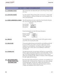
<strong>Parts</strong> List<br />
20 <strong>OM</strong>-<strong>AH</strong>/<strong>1E</strong><br />
To order parts, contact your Groen Certified Service Agency. Supply the model designation, part description, and number, quant ity, and where applicable, voltage<br />
and phase.<br />
Ignition Module Box Assembly<br />
B<br />
A<br />
Front Panel Components Assembly<br />
Gas Valve, Piping & Electrical Control Panel Assembly<br />
20<br />
Electrical Panel Assembly
<strong>OM</strong>-<strong>AH</strong><br />
<strong>OM</strong>-<strong>AH</strong><br />
<strong>Parts</strong> List<br />
To order parts, contact your Groen Certified Service Agency. Supply the model designation, part description, and number, quantity, and where applicable, voltage<br />
and phase.<br />
Key Description Part No. Key Description Part No. Key Description Part No.<br />
G. Gas Valve, Piping & Elec. Ctrl Pan Assy 127335 26 Nut, Hes Keps 1/4-20 095695 Ignition Module Box 127334<br />
3 Water Level Electrode 074665 27 Plug, Pipe Square Head 3/8" NPT 008504 1 Spark Ignition Module Enclosure 123775<br />
4 Electrical Components Assembly 123823 28 Nipple, 1/2" NPT x 1-1/2" long 004184 2 Cover Ignition Module Enclosure 104948<br />
5 Ignition Module Box Assembly 127334 29 Tee reducing 1/2 NPT x 3/8 NPT x 3/8 123865 3 Gasket, Cover 104941<br />
6 Elbow, 90º Union, 1/2" NPT 005495 30 Nipple, 3/8" NPT x Close 007439 4 Screw 8-32 x 3/8" long 005764<br />
7 Nipple, 1/2" NPT x 8" long 005557 31A Elbow, 90º Street 009853<br />
5 Ignition Module 085153<br />
8 Valve, Gas, Manual Shut-Off 1/2" NPT 098458 31B Union 3/8 NPT 005686 6 Nut, Keps 6-32 071289<br />
9 Fitting 90º 1/8" NPT male x 1/4" tube 097195 32 Bolt, HH, 1/4-20 x 3/4" long 005698 7 Conduit, plastic male adapter 1/2" NPT 123733<br />
10 Front Panel Components Assy 123805 35 Boot, Low Water Probe 101143 8 Conduit Nut, 1/2" 005487<br />
11 Pressure Gauge 2" Diameter 099156 37 Nut, Keps 10-32 w/shakeproof washer 071256 9 Screw 10-32 x 3/8" long 069773<br />
12 Sight Tube, 5/8" Dia x 4-3/4" long 008742<br />
13 Fittings, Sight Glass Assembly 002845 Electrical Panel Assembly 123823 Front Panel Components Assembly 123805<br />
14 Guard Rod for Gauge Glass 002981 1 Water Level Control - 24V 122192 1 Label Indicator Lights & Instructions 123803<br />
15 Nut, Hex #10-24 005470 2 Transformer 75A 24V Sec. 120V Pri. 121715 2 Indicator Light Amber w/Bezel 116384<br />
16 Coupling, Full 1/2" NPT 005722<br />
Transfmr 75A 24V Sec. 208-240V Pri. 106234 3 Indicator Light Red w/Bezel 116383<br />
17 Nipple, 1/2" NPT x 2-1/2" Lg. 005552 3 Screw, pan head 8-32 x 3/8" long 005764 4 Thermostat 012313<br />
18 Switch Pressure 1/4" NPT 24 PSIG ± 1 108559 4 Terminal Block, 2 pole #4-#18 AWG 003887 5 Thermostat Adapter (shaft bushing) 107172<br />
19 Nipple, 1/4" NPT x 2-1/2" Lg 127330 5 Label, “3 AMP Fast Blow Only” 102251 6 Screw round head 6-32 x 3/8" long 009697<br />
20 Elbow, 90º 1/4" NPT 005682 6 Fuse Holder 077854 7 Knob, thermostat 012314<br />
21 Valve, Gas 123815 7 Screw, round head 6-32 x 1/4" long 018384 8 Toggle Switch, Spst, On-Off 006904<br />
22 Nipple, 1/2" NPT x 2" long 005551 8 Lug, ground 14-6 AWG 119829<br />
23 Elbow 1/2" NPT 008747 9 Screw round head 8-32 x 1-1/4" long 005056<br />
24 Nipple, 1/2" NPT x 4" long 005554 15 Fuse, 3.0 AMP Type 3 AG 077853<br />
25 Clamp, rigid conduit 3/4" NFPC 127345 16 Electrical Panel 123852<br />
17 Nut, Keps 10-32 w/shakeproof washer 071256<br />
18 Harness, Wiring 123864<br />
21<br />
<strong>OM</strong>-<strong>AH</strong>/<strong>1E</strong> 21
<strong>OM</strong>-<strong>AH</strong><br />
Electrical Schematic<br />
22 <strong>OM</strong>-<strong>AH</strong>/<strong>1E</strong> 22
<strong>OM</strong>-<strong>AH</strong><br />
Service Log<br />
Model No. __________________________________ Purchased From _____________________________<br />
Serial No. __________________________________ Location ___________________________________<br />
Date Purchased _____________________________ Date Installed _______________________________<br />
Purchase Order No. __________________________ For Service Call _____________________________<br />
Date Service Performed Performed By<br />
<strong>OM</strong>-<strong>AH</strong>/<strong>1E</strong> 23
24 <strong>OM</strong>-<strong>AH</strong>/<strong>1E</strong><br />
<br />
<br />
<br />
<br />
<br />
<br />
<br />
<br />
<br />
<br />
<br />
<br />
<br />
<br />
<br />
<br />
<br />
<br />
<br />
<br />
<br />
<br />
<br />
<br />
<br />
<br />
<br />
1055 Mendell Davis Drive • Jackson MS 39272<br />
888-994-7636 • 601-372-3903 • Fax 888-864-7636<br />
groen.com<br />
PART NUMBER 121051, REV. E F (4/06) (5/08)