star-max™ gas griddles chrome-max™ gas griddles - Parts Town
star-max™ gas griddles chrome-max™ gas griddles - Parts Town
star-max™ gas griddles chrome-max™ gas griddles - Parts Town

You also want an ePaper? Increase the reach of your titles
YUMPU automatically turns print PDFs into web optimized ePapers that Google loves.
Star<br />
Manufacturing<br />
International Inc.<br />
10 Sunnen Drive<br />
St. Louis, MO 63143<br />
Phone: (314) 781-2777<br />
Fax: (314) 781-3636<br />
STAR-MAX GAS GRIDDLES<br />
MODELS<br />
615M, 615T, 624M, 624T,<br />
636M, 636T, 648M, 648T,<br />
624TSP, 636TSP, 648TSP<br />
CHROME-MAX GAS GRIDDLES<br />
MODELS<br />
624TCHS, 636TCHS, and 648TCHS<br />
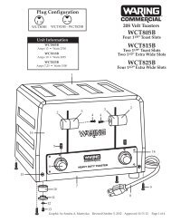
MODEL 624M<br />
1<br />
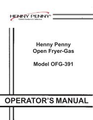
MODEL 636T<br />
Installation<br />
and<br />
Operating<br />
Instructions<br />
2M-Y7131 Rev. I 9/23/02
GENERAL INSTALLATION DATA<br />
CAUTION<br />
This equipment is designed and sold for<br />
commercial use only by personnel trained and<br />
experienced in its operation and is not sold for<br />
consumer use in and around the home nor for<br />
use directly by the general public in food service<br />
locations. For equipment to be used by the<br />
general public, please contact the factory.<br />
The Star-Max model <strong>griddles</strong> are equipped for<br />
use with the types of <strong>gas</strong> specified on the<br />
nameplate.<br />
All units are shipped from the factory for use with<br />
natural <strong>gas</strong>. The unit can easily be converted for<br />
use on propane <strong>gas</strong>: see propane <strong>gas</strong>.<br />
-IMPORTANT-<br />
The installation of the Appliance should<br />
conform to the NATIONAL FUEL GAS CODE<br />
"ANSI Z223.1 - LATEST EDITION" AND ALL<br />
LOCAL GAS COMPANY RULES AND<br />
REGULATIONS.<br />
IN CANADA INSTALLATION SHALL BE IN<br />
ACCORDANCE WITH THE CURRENT<br />
CAN/CGA-B149.1 NATURAL GAS<br />
INSTALLATION CODE OR CAN/CGA-<br />
B149.2 PROPANE INSTALLATION CODE<br />
AND LOCAL CODES WHERE APPLICABLE.<br />
WARNING: Improper installation,<br />
adjustment, alteration, service or maintenance<br />
can cause property damage, injury or death.<br />
Read the installation, operating and<br />
maintenance instructions thoroughly before<br />
installing or servicing the equipment.<br />
FOR YOUR SAFETY<br />
DO NOT STORE OR USE GASOLINE OR<br />
OTHER FLAMMABLE VAPORS AND LIQUIDS<br />
IN THE VICINITY OF THIS OR ANY OTHER<br />
APPLIANCE. KEEP THE APPLIANCE AREA<br />
CLEAR AND FREE FROM COMBUSTIBLES.<br />
2<br />
This appliance, its pressure regulator and its<br />
individual shutoff valve must be disconnected from<br />
the <strong>gas</strong> supply piping system during any pressure<br />
testing of that system at test pressures in excess<br />
of 1/2 PSIG (3.45KPA). This appliance and its<br />
pressure regulator must be isolated from the <strong>gas</strong><br />
supply piping system by closing its individual<br />
manual shutoff valve during any pressure testing of<br />
the <strong>gas</strong> supply piping system at test pressures<br />
equal to or less than 1/2 PSIG (3.45KPA). For<br />
your protection, we recommend a qualified<br />
installing agency install this appliance. They should<br />
be familiar with <strong>gas</strong> installations and your local <strong>gas</strong><br />
requirements. In any case, your <strong>gas</strong> company<br />
should be called to approve the final installation. In<br />
addition, there should be posted, in a prominent<br />
location, detailed instructions to be followed in<br />
the event the operator smells <strong>gas</strong>. Obtain the<br />
instructions from the local <strong>gas</strong> supplier.<br />
FOR YOUR SAFETY<br />
IF YOU SMELL GAS<br />
1. DO NOT TOUCH ELECTRICAL<br />
SWITCHES.<br />
2. EXTINGUISH ANY OPEN FLAME.<br />
3. IMMEDIATELY CALL YOUR GAS<br />
COMPANY.<br />
KEEP THE APPLIANCE AREA FREE AND<br />
CLEAR FROM COMBUSTIBLES.<br />
CLEARANCE<br />
For use on non-combustible countertops<br />
only. Combustible and non-combustible material<br />
must be at least 48" (120cm) from the top of the<br />
appliance and 6" (150mm) from the sides and<br />
back. Adequate clearance should also be provided<br />
for proper operation and servicing.<br />
AIR SUPPLY<br />
Make certain not to obstruct the flow of<br />
combustion and ventilation air. Provisions for<br />
adequate air supply must be furnished. Make<br />
certain that air intake openings in the bottom of<br />
the appliance are not obstructed. They are<br />
essential for proper combustion and operation of<br />
the appliance.
EXHAUST CANOPY<br />
It is essential that facilities be provided over the<br />
griddle to carry off fumes and <strong>gas</strong>es. However,<br />
the unit should not be directly connected to a flue<br />
or stack.<br />
LEVELING UNIT<br />
This griddle is supplied with (4) feet which must be<br />
screwed into the legs attached to the body. Level<br />
unit by adjusting the (4) feet which have an<br />
adjustment of 1-3/4" (43.75mm) for accurate and<br />
perfect lineup with other units. CAUTION: DO<br />
NOT INSTALL WITHOUT ATTACHING FEET -<br />
DO NOT REMOVE FEET.<br />
MANUAL SHUT OFF VALVE<br />
A manual shut off valve should be installed<br />
upstream from the union and within 6 feet<br />
(1.829m) of this appliance.<br />
GAS PRESSURE REGULATOR<br />
A convertible pressure regulator is provided with<br />
each griddle. It should be connected to the inlet<br />
pipe at the rear of the unit. The <strong>gas</strong> supply line is<br />
then connected to it. It is shipped set for 6"<br />
(15.24cm) water column manifold pressure for<br />
use with natural <strong>gas</strong>.<br />
GAS PIPING<br />
Gas piping shall be of such size and so installed as<br />
to provide a supply of <strong>gas</strong> sufficient to meet the<br />
full <strong>gas</strong> input of the appliance. If the appliance is to<br />
be connected to existing piping, it shall be checked<br />
to determine if it has adequate capacity. Joint<br />
compound (pipe dope) shall be used sparingly and<br />
only on the male threads of the pipe joints. Such<br />
compounds shall be resistant to the action of L.P.<br />
<strong>gas</strong>es. To connect to <strong>gas</strong> supply, attach pipe nipple<br />
provided with unit, attach pressure regulator to<br />
nipple, and <strong>gas</strong> supply to regulator. WARNING:<br />
Any loose dirt or metal particles which are<br />
allowed to enter the <strong>gas</strong> lines on this appliance will<br />
damage the valve and affect its operation. When<br />
installing this appliance, all pipe and fittings must be<br />
free from loose dirt.<br />
3<br />
CHECKING FOR GAS LEAKS<br />
Soap and water solution or other material<br />
acceptable for the purpose, shall be used in<br />
locating <strong>gas</strong> leakage. Matches, candle flame or<br />
other sources of ignition shall not be used for this<br />
purpose. Check entire piping system for leaks.<br />
PROPANE GAS<br />
This griddle is equipped with fixed orifice hoods<br />
and is shipped from the factory for use on natural<br />
<strong>gas</strong>. To convert to propane <strong>gas</strong>, install the #55*<br />
burner orifice hoods supplied, behind the control<br />
panel as follows:<br />
1. Remove front panel by removing screws<br />
located on the front and the bottom.<br />
2. Remove firewall shield and screws from<br />
burner bracket.<br />
3. Remove burner(s) from orifice of hood(s). This<br />
is accomplished by lifting up on the rear of the<br />
burner(s) and sliding the burner(s) off of the<br />
hood(s).<br />
4. Remove natural <strong>gas</strong> orifice hood(s) and install<br />
the propane hood(s) furnished.<br />
5. Reinstall burner(s).<br />
Note: Steps 2, 3, and 5 apply to MA models only.<br />
* TCHS & TSP Series (w/safety pilots) use a #41<br />
drill orifice for natural <strong>gas</strong> and a #52 drill orifice<br />
for propane <strong>gas</strong>.<br />
6. Reinstall front panel.<br />
7. Set manifold pressure to 10" (25.4cm) water<br />
column. A 1/8" pipe plug on the supply pipe can<br />
be removed for attaching a pressure gauge.<br />
Remove the slotted, or hex-threaded, plug<br />
from the pressure regulator. Invert the plug<br />
and re-install. The letters "LP" should now be<br />
visible on the plug. The regulator is now set<br />
for 10" (25.4 cm) water column.<br />
PILOT LIGHT REGULATION<br />
The pilot lights on this griddle have been turned<br />
off at the factory. Adjust pilot light flames as small<br />
as possible, but high enough to light burner<br />
immediately when burner valve is turned on high.
BURNER OPERATION (MODELS 615M,<br />
624M, 636M, and 648M ONLY)<br />
To ignite burners, turn burner valve knob to "HI"<br />
position. Each burner is controlled by an individual<br />
high-low, on-off valve. An infinite number of<br />
temperatures may be obtained by turning the<br />
burner valve knob to any position between high<br />
and low.<br />
BURNER ADJUSTMENT (MODELS 615M,<br />
624M, 636M, and 648M ONLY)<br />
1. Turn burner valve knob to "HI" position.<br />
2. Slowly decrease opening of air shutters to<br />
give a soft blue flame having luminous tips,<br />
then slowly increase openings to a point where<br />
the yellow tips disappear and a hard blue flame<br />
is obtained.<br />
3. Set the low adjustment to maintain<br />
approximately 1/8" (3.175mm) high flame by<br />
turning the screws inside the valve shafts when<br />
the knob is turned to low.<br />
BURNER ADJUSTMENT (MODELS 615T,<br />
624T, 636T, 648T, TCHS & TSP ONLY)<br />
1. Push dial in and set thermostat of one burner<br />
to 450°F (229.9°C).<br />
2. Observing flame through lighting hole, close<br />
the air shutter to give a soft blue flame having<br />
luminous tips and open to a point where the<br />
yellow tips disappear, and a hard blue flame is<br />
obtained. Repeat for all burners.<br />
LIGHTING INSTRUCTIONS<br />
When griddle is first lit, it will smoke until the<br />
preservation oils and impurities are burned off.<br />
1. Turn off main valve to unit and wait 5 minutes<br />
to clear <strong>gas</strong>.<br />
2. Turn off all knobs and pilot valves.<br />
3. Turn on main valve and light all pilots.<br />
4. Turn burner knobs to desired setting.<br />
5. To turn burners off, turn knobs off.<br />
NOTE: The <strong>griddles</strong> are equipped with standing<br />
pilots and should be lit immediately after the <strong>gas</strong> is<br />
turned on.<br />
4<br />
LIGHTING INSTRUCTIONS (TCHS &<br />
TSP SERIES)<br />
1. Turn the thermostat knob(s) and pilot valves<br />
to "OFF" position. CAUTION: If <strong>gas</strong> valves<br />
have been on and <strong>gas</strong> has escaped through the<br />
burners, turn unit off and wait 5 minutes to<br />
clear <strong>gas</strong>.<br />
2. Turn on pilot valve, depress and hold reset<br />
button, light pilot, hold reset button for 60<br />
seconds, or until pilot stays lit (repeat for all<br />
pilots.)<br />
3. Set thermostat(s) to desired temperature.<br />
4. If burners do not light repeat steps 1 thru 4.<br />
5. Turn off thermostats and pilot valves for<br />
complete shutdown.<br />
ADJUSTING BY-PASS (MINIMUM<br />
FLAME-MODELS 615T, 624T, 636T, 648T,<br />
TCHS & TSP ONLY)<br />
Enough <strong>gas</strong> must be by-passed through the<br />
thermostat to keep the entire burner lit after the<br />
thermostat action has reduced the flame on the<br />
burner. To allow accurate control of<br />
temperature, be sure to set the by-pass<br />
adjustment accurately. To make this adjustment,<br />
proceed as follows.<br />
1. Light the main burner(s).<br />
2. Set the thermostat dial(s) at 350°F (174.9°C).<br />
3. Allow the griddle to heat until the thermostat<br />
action has cut down the flame on the<br />
burner(s). This will take about 10 minutes.<br />
4. Set the thermostat dial(s) at 150°F (64.9°C)<br />
and observe flame.<br />
5. The burner flame should now not exceed 1/8"<br />
in height. If adjustment is needed, remove<br />
dial(s), turn the by-pass adjustment screw on<br />
the thermostat clockwise to decrease until the<br />
flame over the entire burner is not more than<br />
1/8" (3.175mm) in height.
ADJUSTING THERMOSTATS (MODELS<br />
615T, 624T, 636T, 648T, TCHS & TSP<br />
ONLY)<br />
The thermostat is a precision instrument. It has<br />
been carefully calibrated at the factory. Field<br />
recalibration is seldom necessary and should not<br />
be done until the by-pass flame has been adjusted.<br />
To measure griddle temperature use a reliable<br />
pyrometer and proceed as follows.<br />
1. Set dial to 400°F (202.4°C), lighting burner.<br />
2. After burner has been on about 10 minutes,<br />
check griddle surface temperature above<br />
operating thermostat.<br />
3. Continue to check temperature at 5 minute<br />
intervals, until two successive readings are<br />
within 5 degrees of each other. If your reading<br />
is not within 10 degrees of the dial setting<br />
400°F (202.4°C), recalibration is required.<br />
4. Remove dial completely with "D" type stem.<br />
5. Turn calibration screw clockwise to obtain a<br />
lower temperature or counterclockwise for a<br />
higher temperature. Each mark on retainer<br />
represents 25°F (13.75°C).<br />
6. Repeat steps for other thermostats.<br />
ADJUSTING SAFETY PILOTS<br />
(SERIES TCHS & TSP ONLY)<br />
A rotor valve is provided to manually adjust pilot<br />
flame size. "OFF" and "ON" positions are<br />
indicated on valve. By slowly turning the<br />
adjustment knob, a desirable pilot flame can be<br />
obtained.<br />
OVERNIGHT SHUTDOWN<br />
Turn knobs to the off position to turn burners off.<br />
OPERATING INSTRUCTIONS<br />
SEASONING THE GRIDDLE HEATING<br />
SURFACE (NON-CHROMIUM)<br />
Clean the griddle surface thoroughly. After the<br />
griddle has been thoroughly cleaned, it should be<br />
seasoned to prevent food from sticking. Before<br />
using, and after each thorough scouring, season<br />
the griddle heating surface in the following<br />
manner:<br />
1. Turn the temperature control dial to 350°F<br />
(174.9°C).<br />
5<br />
2. Using a clean cloth, not a spatula, spread a thin<br />
film of cooking oil or fat over the griddle<br />
cooking surface. This film should remain on<br />
the hot griddle surface 1/2 hour.<br />
3. Remove excess fat and wipe clean.<br />
4. Apply another film of cooking oil over the hot<br />
cooking area for another 1/2 hour, and again<br />
remove excess fat and wipe clean. The griddle<br />
surface should now be ready for use.<br />
Even with careful seasoning food may, to some<br />
extent, stick to the griddle cooking surface until<br />
griddle plate is "broken in".<br />
COOKING (MODELS 615T, 624T, 636T,<br />
648T, TCHS & TSP ONLY)<br />
Set the thermostat dial knob to the temperature<br />
desired. After a short preheating period, the<br />
thermostat will automatically maintain the<br />
selected temperature.<br />
GRIDDLE CARE (NON-CHROMIUM<br />
SURFACES)<br />
It takes very little time and effort to keep the<br />
griddle attractive and performing at top efficiency.<br />
If grease is permitted to accumulate, it will form a<br />
gummy cake and then carbonize into a hard<br />
substance which is extremely difficult to remove.<br />
To prevent this condition, the following<br />
suggestions for cleanliness should be followed.<br />
1. After each use, scrape the griddle with a<br />
scraper or flexible spatula to remove excess fat<br />
and food. A waste drawer is provided for the<br />
scrapings. If there is an accumulation of burned<br />
on fat and food, the griddle should be<br />
thoroughly scoured and reseasoned. Use<br />
pumice or griddle stone while the griddle is<br />
warm. Do not use steel wool because of the<br />
danger of steel slivers getting into the food.<br />
2. Daily-use a clean cloth and good non-abrasive<br />
cleaner to clean the stainless steel body of the<br />
griddle. Wipe the polished front with a soft<br />
cloth.<br />
3. At least once a day, remove the waste drawer<br />
and wash in the same way as an ordinary<br />
cooking utensil. The drawer is removed by<br />
pulling forward, up and out.
GRIDDLE CARE (CHROMIUM<br />
SURFACES)<br />
It takes very little time and effort to keep this<br />
Industrial Chromium griddle surface sparkling<br />
clean and performing at top efficiency. DO NOT<br />
allow grease to accumulate as it will carbonize and<br />
becomes difficult to remove. To prevent this<br />
condition the following cleaning suggestions<br />
should be followed.<br />
1. Remove excess oil and food regularly with a 4"<br />
(100mm) wide Razor Sharp type scraper and<br />
wipe surface with a damp cloth if desired.<br />
2. Following the scraping, for end of the day<br />
cleaning, a damp cloth and a non-silicated,<br />
non-abrasive, non-chlorinated cleaner such as<br />
Bon-Ami may be used to wipe surface clean,<br />
followed by wiping with clean wet cloth.<br />
3. Follow steps 2 and 3 from Griddle Care (Non-<br />
Chromium Surfaces) from page 4.<br />
CAUTION<br />
1. Never use Pumice, griddle stones, or<br />
abrasives on the surface.<br />
2 Never strike griddle surface with sharp<br />
instrument or spatula edge.<br />
3. Never use steel wool.<br />
4. Never use commercial liquid grill cleaner<br />
on the griddle surface.<br />
5. Abusing surface voids the warranty.<br />
GREASE PAN<br />
A grease pan is located at the front and can be<br />
removed from the front for cleaning. This pan<br />
should be checked and emptied when necessary.<br />
CAUTION<br />
EXERCISE EXTREME CARE IN HANDLING<br />
THE GREASE PAN CONTAINING HOT<br />
GREASE.<br />
6<br />
MAINTENANCE AND REPAIRS<br />
Contact the factory or one of its representatives<br />
or a local service company for service or<br />
maintenance if required.<br />
CHROME-MAX GRIDDLE SURFACE<br />
LIMITED WARRANTY EXCLUSIONS<br />
Your Chrome-Max griddle has been designed to<br />
give you many years of cooking reliability and<br />
requires minimum maintenance to keep the<br />
<strong>chrome</strong> surface in its original condition. All<br />
Chrome-Max griddle surfaces are warranted for<br />
a period of 5 years against manufacturing defects<br />
to the original owner from the date of installation.<br />
This limited warranty is void if it is determined by<br />
Star Manufacturing International Incorporated or<br />
one of its' authorized representatives that the<br />
<strong>chrome</strong> surface has been misused or abused or<br />
subjected to the following situations:<br />
1. Improperly installed.<br />
2. By-pass adjustments not set properly on <strong>gas</strong><br />
units allowing the appliance to overheat and<br />
discolor the <strong>chrome</strong> surface. (See by-pass<br />
adjustment in instruction manual supplied<br />
with unit).<br />
3. Incorrect voltage applied to electric<br />
Chrome-Max units allowing the surface to<br />
overheat and discolor.<br />
4. The misuse of any instrument or tool which<br />
scratches or makes indentations in the<br />
surface which could cause the surface to<br />
peel, flake, or chip off.<br />
5. The use of any chemical or abrasive<br />
cleaning solution, griddle brick, stone,<br />
screen or other cleaning products which<br />
could damage and affect the performance<br />
of the <strong>chrome</strong> surface.<br />
6. The neglect of daily routine maintenance to<br />
the chromium surface.<br />
RETAIN THIS MANUAL FOR FUTURE REFERENCE<br />
Part No. 2M-Y7131 Rev. I 9/23/02
PARTS LIST EFFECTIVE<br />
Key<br />
Number<br />
Part<br />
Number<br />
MODEL<br />
Number<br />
Per<br />
Unit<br />
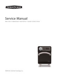
615T & 624T Star-Max Gas Griddle<br />
15" and 24" Thermostatic Control<br />
IMPORTANT: WHEN ORDERING, SPECIFY VOLTAGE OR TYPE GAS DESIRED PAGE<br />
INCLUDE MODEL AND SERIAL NUMBER OF<br />
Some items are included for illustrative purposes only and in certain instances may not be available.<br />
12<br />
Description<br />
1 2R-9193 1/2 BUTTON-INDICATOR 615T/624T<br />
2 2R-8229 2/4 SHIELD-KNOB 615T/624T<br />
3 2R-9499 1/2 KNOB-CONTROL 615T/624T<br />
4 G3-Y7154 1 FRONT PANEL 615T<br />
4 G3-Y7018 1 FRONT PANEL 624T<br />
5 G3-Y7153 1 FACEPLATE 615T<br />
5 G3-Y7017 1 FACEPLATE 624T<br />
6 2A-Y7113 4 LEG<br />
7 G3-624009 1 GRIDDLE PLATE ASSEMBLY 615T<br />
7 G3-624005 1 GRIDDLE PLATE ASSEMBLY 624T<br />
8 G3-Y7046 1 GREASE DRAWER GRIDDLE<br />
9 G3-Y7047 2 SLIDE DRAWER<br />
10 2F-Y7052 1/2 BURNER ASSEMBLY 615T/624T<br />
11 G3-624047 1 MANIFOLD ASSEMBLY COMPLETE 615T<br />
11 G3-624006 1 MANIFOLD ASSEMBLY COMPLETE 624T<br />
12 2P-1453 1 PLUG-PIPE<br />
13 2V-6671 1/2 VALVE-PILOT 615T/624T<br />
14 G3-T1022 1/2 ORIFICE TUBE 615T/624T<br />
15 2J-Y7216 1/2 HOOD BURNER #47 NAT. 615T/624T<br />
16 2A-9369 1/2 ORIFICE-FITTING 615T/624T<br />
17 2K-Y7111 1/2 FITTING COMPRESSION 615T/624T<br />
18 2T-Y7159 1/2 THERMOSTAT 615T/624T<br />
19 2K-Y7123 1 INLET PIPE<br />
20 G3-Y7252 1 INLET PIPE SUPPORT<br />
21 G3-Y7355 1/2 TUBE-PILOT 615T/624T<br />
22 G3-Y7356 1/2 PILOT BRACKET 615T/624T<br />
23 2J-Y7250 1/2 ORIFICE #55 L.P. 615T/624T<br />
24 2J-Y7589 1 REGULATOR-PRESSURE (CONVERTIBLE)<br />
25 G3-Y7039 1/2 BULB-CLAMP 615T/624T<br />
26 G3-Y7040 1/2 TENSIONER 615T/624T<br />
Star Manufacturing International, Inc.<br />
Rev. I 9/23/02<br />
1<br />
2
PARTS LIST EFFECTIVE<br />
Key<br />
Number<br />
Part<br />
Number<br />
MODEL<br />
Number<br />
Per<br />
Unit<br />
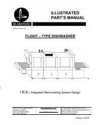
636T & 648T Star-Max Gas Griddle<br />
36" and 48" Thermostatic Control<br />
IMPORTANT: WHEN ORDERING, SPECIFY VOLTAGE OR TYPE GAS DESIRED PAGE<br />
INCLUDE MODEL AND SERIAL NUMBER OF<br />
Some items are included for illustrative purposes only and in certain instances may not be available.<br />
13<br />
Description<br />
1 2R-9193 3/4 BUTTON INDICATOR 636T/648T<br />
2 2R-8229 6/8 SHIELD-KNOB 636T/648T<br />
3 2R-9499 3/4 KNOB-CONTROL 636T/648T<br />
4 G3-Y7010 1 FRONT PANEL 636T<br />
4 G3-Y7007 1 FRONT PANEL 648T<br />
5 G3-Y7009 1 FACEPLATE, LEFT/RIGHT 636T<br />
5 G3-Y7008 1 FACEPLATE, LEFT/RIGHT 648T<br />
6 2A-Y7113 4 LEG<br />
7 G3-624010 1 GRIDDLE PLATE ASSEMBLY 636T<br />
7 G3-624011 1 GRIDDLE PLATE ASSEMBLY 648T<br />
8 G3-Y7046 1 GREASE DRAWER GRIDDLE<br />
9 G3-Y7047 2 SLIDE DRAWER<br />
10 2F-Y7052 3/4 BURNER ASSEMBLY 636T/648T<br />
11 G3-624048 1 MANIFOLD ASSEMBLY COMPLETE 636T<br />
11 G3-624049 1 MANIFOLD ASSEMBLY COMPLETE 648T<br />
12 2P-1453 1 PLUG-PIPE<br />
13 2V-6671 3/4 VALVE-PILOT 636T/648T<br />
14 G3-T1022 3/4 ORIFICE TUBE 636T/648T<br />
15 2J-Y7216 3/4 HOOD BURNER #47 NAT. 636T/648T<br />
16 2A-9369 3/4 ORIFICE-FITTING 636T/648T<br />
17 2K-Y7111 3/4 FITTING COMPRESSION 636T/648T<br />
18 2T-Y7159 3/4 THERMOSTAT 636T/648T<br />
19 2K-Y7123 1 INLET PIPE<br />
20 G3-Y7252 1 INLET PIPE SUPPORT<br />
21 G3-Y7355 3/4 TUBE-PILOT 636T/648T<br />
22 G3-Y7356 3/4 PILOT BRACKET 636T/648T<br />
23 2J-Y7250 3/4 ORIFICE #55 L.P. 636T/648T<br />
24 2J-Y7589 1 REGULATOR-PRESSURE (CONVERTIBLE)<br />
25 G3-Y7039 3/4 BULB-CLAMP 636T/648T<br />
26 G3-Y7040 3/4 TENSIONER 636T/648T<br />
Star Manufacturing International, Inc.<br />
Rev. I 9/23/02<br />
2<br />
2