Mobile Mapping Systems - University of Glasgow
Mobile Mapping Systems - University of Glasgow
Mobile Mapping Systems - University of Glasgow

You also want an ePaper? Increase the reach of your titles
YUMPU automatically turns print PDFs into web optimized ePapers that Google loves.
[a] [b]<br />
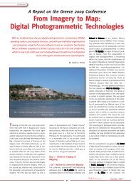
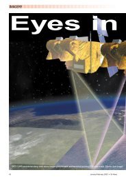
Fig. 13 – (a) This IP-S2 “Integrated Positioning System” from Topcon Positioning<br />
<strong>Systems</strong> has been mounted on a raised platform and located at the rear <strong>of</strong> an<br />
open-backed truck.<br />
(b) A close-up photo <strong>of</strong> the IP-S2 imaging, laser scanning and positioning sub-systems.<br />
At the foot <strong>of</strong> the photo is the yellow Topcon controller unit; adjacent to<br />
this unit to the left and right are two white SICK LMS 291 laser scanners; sitting<br />
on top <strong>of</strong> the control box is the system IMU; sitting on a bracket above the IMU<br />
is the red Ladybug3 multiple camera unit; while at the top <strong>of</strong> the stack on a<br />
small mast is the antenna <strong>of</strong> the Topcon GNSS receiver. (Source: Topcon)<br />
encoder operating at 30 Hz to complete the overall positioning capability<br />
for the IP-S2 system. Besides these positioning devices, the imaging<br />
and laser scanning capabilities <strong>of</strong> the IP-S2 are based on well-known<br />
units that are available <strong>of</strong>f-the-shelf. They include the Ladybug multicamera<br />
unit from Point Grey Research that carries out the 360 degree<br />
panoramic imaging with framing rates <strong>of</strong> up to 15 frames per second.<br />
The laser scanning that is carried out using the standard configuration<br />
<strong>of</strong> the IP-S2 is provided by three Sick LMS 291 scanners operating at<br />
75 Hz. One <strong>of</strong> these laser scanners is pointing directly forwards (or<br />
backwards) towards the road in front <strong>of</strong> (or behind) the vehicle, while<br />
the other two scanners point to each side to provide a continuous<br />
series <strong>of</strong> range or elevation pr<strong>of</strong>iles within the vertical plane. All <strong>of</strong><br />
these imaging and scanning devices send their data to a central control<br />
box which then passes it via a high-speed FireWire-B (IEEE1394-B)<br />
link to the PC that is mounted in the vehicle for the recording and processing<br />
<strong>of</strong> the data. An LCD display screen allows the vehicle’s crew to<br />
monitor the connectivity and operation <strong>of</strong> all the various positioning,<br />
laser scanning and frame imaging devices.<br />
In the version <strong>of</strong> the system that is used in the Google Street View<br />
vehicles, the Ladybug multiple camera has been replaced by Google’s<br />
own multiple camera system [Fig. 5], which is based on the use <strong>of</strong><br />
Elphel digital frame cameras. Although the IP-S2 system has only been<br />
<strong>of</strong>fered for sale by Topcon quite recently, already an example is in operation<br />
by the Geodis surveying and mapping company based in Brno in<br />
the Czech Republic.<br />
Mitsubishi<br />
Another Japanese system supplier is the Mitsubishi Electric Corporation,<br />
whose IT Space Solutions Department showed its MMS (<strong>Mobile</strong> <strong>Mapping</strong><br />
System) [Fig. 14] at the Intergeo trade fair held in Karlsruhe, Germany in<br />
September 2009. This product has been developed jointly by staff members<br />
<strong>of</strong> Waseda <strong>University</strong> in Tokyo in collaboration with Mitsubishi since<br />
2006. Several examples are already in use in Japan. The system is being<br />
<strong>of</strong>fered in three different versions. (i) The most basic version is the MMS-<br />
A, which has three ro<strong>of</strong>-mounted GNSS receivers arranged in a triangular<br />
pattern; an IMU; an odometer; and a sensor control box. This version is<br />
being <strong>of</strong>fered mainly as a vehicle positioning device, with the choice <strong>of</strong><br />
cameras and laser scanners and their integration being left to the customer.<br />
(ii) The second version is the MMS-S which is <strong>of</strong>fered with two<br />
video cameras and two laser scanners in addition to the positioning<br />
devices included in the basic MMS-A version. (iii) Finally the MMS-X version<br />
is <strong>of</strong>fered with multiple (up to 6) cameras and (up to 4) laser scanners,<br />
again in addition to the positioning instrumentation included in the<br />
Latest News? Visit www.geoinformatics.com<br />
39<br />
Article<br />
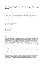
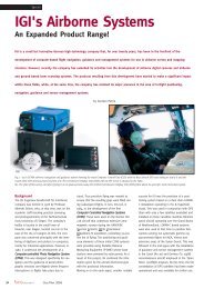
Fig. 14 – This van is equipped with a<br />
Mitsubishi MMS mobile mapping system,<br />
showing its cameras, laser scanners<br />
and three GPS antennas mounted<br />
together on its ro<strong>of</strong> platform.<br />
(Source: Mitsubishi Electric)<br />
MMS-A version. In the literature<br />
that accompanied this introduction,<br />
the supplier <strong>of</strong> the dual-frequency<br />
GNSS receivers was stated<br />
to be Trimble; the IMU was<br />
from Crossbow, using a FOG gyro<br />
supplied by Japan Aviation<br />
Electronics; the frame cameras<br />
were supplied by IMPERX from the United States; while the laser scanners<br />
were the ubiquitous LMS 291 model from SICK.<br />
Trimble<br />
The mobile mapping systems that are being supplied by Trimble’s<br />
GeoSpatial Division were developed originally by the Geo-3D company,<br />
which is based at Brossard, near Montreal in Canada and was acquired by<br />
Trimble in January 2008. Its main product has been its Trident-3D mobile<br />
mapping system. This has been fitted on a variety <strong>of</strong> different vehicles and<br />
in a number <strong>of</strong> different configurations as specified by the customers. Digital<br />
video and still frame cameras from various suppliers have been fitted –<br />
including, in one case, the use <strong>of</strong> a Redlake multi-spectral camera – while<br />
the laser scanners that have been used have been supplied by SICK and<br />
Riegl. The DGPS/ IMU systems that are used for geo-positioning have been<br />
the POS LV units supplied by Applanix (another Trimble company), including<br />
Trimble GPS receivers. The system controller and rack-mounted computers<br />
that form parts <strong>of</strong> the overall system were built-up by Geo-3D, which<br />
has also supplied the distance measuring instrument (DMI). Various display<br />
options were also <strong>of</strong>fered by Geo-3D. The latest version <strong>of</strong> this vehicle-based<br />
mapping system is now called the Trimble Cougar system [Fig.<br />
15]. Besides the hardware aspects <strong>of</strong> the overall system, Geo-3D had also<br />
developed a series <strong>of</strong> s<strong>of</strong>tware packages for use with the Trident-3D system.<br />
These have included the Kronos package for survey data acquisition;<br />
Trident-3D Analyst for data extraction and processing, including the semiautomatic<br />
detection, recognition and extraction <strong>of</strong> objects such as road<br />
signs; and Trident-3D Vision for image viewing and analysis.<br />
The majority <strong>of</strong> customers for the Trident-3D mobile mapping system are<br />
agencies that are involved in road surveys, including federal, state, provincial<br />
and municipal departments <strong>of</strong> transport and a number <strong>of</strong> engineering<br />
companies that provide services to these agencies. In total, over 50 Trident-<br />
3D systems have been sold, the majority in North America. However around<br />
a dozen are in operation in Europe, principally in France and Belgium.<br />
Optech<br />
Optech, which is based near Toronto in Canada, entered the field <strong>of</strong> mobile<br />
mapping towards the end <strong>of</strong> 2007, when it released a completely new<br />
product, called the LYNX <strong>Mobile</strong> Mapper [Fig. 16]. This includes a purposebuilt<br />
spinning laser pr<strong>of</strong>iling system that is designed specifically for attachment<br />
to standard vehicle ro<strong>of</strong> racks with mounts for two <strong>of</strong> these laser<br />
scanners and two (optional) calibrated digital frame cameras in its standard<br />
configuration. The LYNX system also includes an Applanix POS LV<br />
sub-system, complete with its IMU; a dual-frequency GPS receiver and<br />
antenna; and a Distance Measuring Instrument (DMI), for coordinate positioning<br />
purposes. The laser scanners that are used in the LYNX system<br />
are built in-house by Optech and utilize a Class I laser as the basis for<br />
their laser rangefinders. They have a maximum range <strong>of</strong> 100 m; a full cir-<br />
January/February 2010