Mobile Mapping Systems - University of Glasgow
Mobile Mapping Systems - University of Glasgow
Mobile Mapping Systems - University of Glasgow

You also want an ePaper? Increase the reach of your titles
YUMPU automatically turns print PDFs into web optimized ePapers that Google loves.
Article<br />
An Introduction to the Technology<br />
<strong>Mobile</strong> <strong>Mapping</strong> <strong>Systems</strong><br />
Over the last 20 years, mobile mapping systems have slowly developed, at first mainly in academic research<br />
establishments. More recently, a number <strong>of</strong> commercially operated systems have appeared. These have mostly been<br />
one-<strong>of</strong>f systems that have been developed in-house by the companies that are operating them. Most <strong>of</strong> them have been<br />
utilized for the collection <strong>of</strong> data on road infrastructure or building facades. However, over the last two or three years,<br />
some very big companies such as Google, Tele Atlas and NAVTEQ have adopted the technology on a large scale,<br />
introducing substantial fleets <strong>of</strong> mobile mapping vehicles for their imaging and mapping operations. This has resulted<br />
in the further rapid development <strong>of</strong> the technology which can now be regarded as being well established and proven.<br />
This article <strong>of</strong>fers an introduction to and survey <strong>of</strong> the present state-<strong>of</strong>-the-art <strong>of</strong> the technology.<br />
This survey <strong>of</strong> the technology will be conducted in three main parts.<br />
(i) The first deals with the main components <strong>of</strong> mobile mapping systems.<br />
These include the digital imaging devices; the laser ranging and<br />
scanning devices; and the positioning (or geo-referencing) devices which<br />
are the principal building blocks that are being used in the construction<br />
<strong>of</strong> such systems. (ii) The second part will cover the system suppliers<br />
who integrate these different components and <strong>of</strong>fer the resulting<br />
systems for sale to users. (iii) The third part covers a representative<br />
selection <strong>of</strong> service providers, but paying particular attention to the<br />
systems used by the large imaging and mapping organisations that<br />
have been mentioned above in the introduction to this article.<br />
I - Main Components<br />
Imaging Devices<br />
Arising from the speed <strong>of</strong> movement <strong>of</strong> the mapping vehicles and the<br />
close proximity <strong>of</strong> the target objects (<strong>of</strong> a few tens <strong>of</strong> metres), the digital<br />
frame cameras and pushbroom line scanners that are familiar to the<br />
mapping community from their airborne imaging operations are simply<br />
not suitable for use with mobile mapping vehicles. Although imaging<br />
(pushbroom) line scanners have been used experimentally in certain<br />
mobile mapping vehicles that are being operated by academic research<br />
groups, so far they have had little use in commercial mapping operations.<br />
Instead digital frame cameras are used almost universally.<br />
However the format sizes are very small (1 to 2 Megapixels is typical);<br />
framing rates are high (typically 7 to 15 frames per second); exposure<br />
times are very short (to eliminate image blur); and the use <strong>of</strong> multiple<br />
camera arrays to provide 360 degree panoramic images in the horizontal<br />
plane is very common. Taking as an example a mobile mapping<br />
vehicle that is being driven in an urban area at 30 kph, it travels a distance<br />
<strong>of</strong> 1 km in 120 seconds or 8.3 m in one second. If it travels at<br />
60 kph, it travels a distance <strong>of</strong> 16.7 m in one second. If the imaging<br />
system has to acquire successive sets <strong>of</strong> frame images at intervals <strong>of</strong> 2<br />
to 8 m from four to eight cameras simultaneously to ensure the continuous<br />
coverage <strong>of</strong> a street or road, then it is obvious that very high<br />
rates <strong>of</strong> data transmission and storage <strong>of</strong> the images will need to be<br />
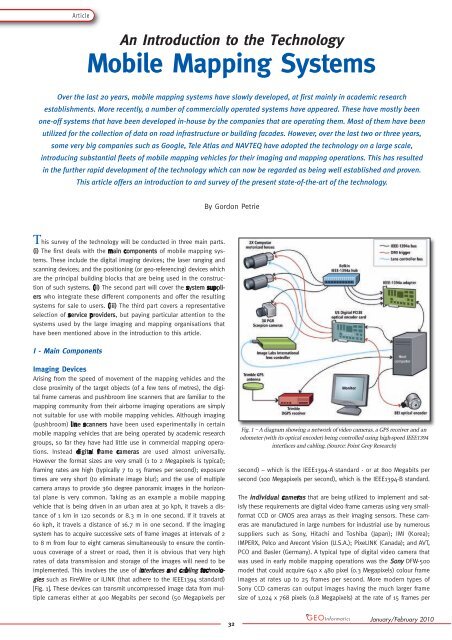
implemented. This involves the use <strong>of</strong> interfaces and cabling technologies<br />
such as FireWire or iLINK (that adhere to the IEEE1394 standard)<br />
[Fig. 1]. These devices can transmit uncompressed image data from multiple<br />
cameras either at 400 Megabits per second (50 Megapixels per<br />
By Gordon Petrie<br />
32<br />
Fig. 1 – A diagram showing a network <strong>of</strong> video cameras, a GPS receiver and an<br />
odometer (with its optical encoder) being controlled using high-speed IEEE1394<br />
interfaces and cabling. (Source: Point Grey Research)<br />
second) – which is the IEEE1394-A standard - or at 800 Megabits per<br />
second (100 Megapixels per second), which is the IEEE1394-B standard.<br />
The individual individual cameras cameras that are being utilized to implement and satisfy<br />
these requirements are digital video frame cameras using very smallformat<br />
CCD or CMOS area arrays as their imaging sensors. These cameras<br />
are manufactured in large numbers for industrial use by numerous<br />
suppliers such as Sony, Hitachi and Toshiba (Japan); IMI (Korea);<br />
IMPERX, Pelco and Arecont Vision (U.S.A.); PixeLINK (Canada); and AVT,<br />
PCO and Basler (Germany). A typical type <strong>of</strong> digital video camera that<br />
was used in early mobile mapping operations was the Sony DFW-500<br />
model that could acquire 640 x 480 pixel (0.3 Megapixels) colour frame<br />
images at rates up to 25 frames per second. More modern types <strong>of</strong><br />
Sony CCD cameras can output images having the much larger frame<br />
size <strong>of</strong> 1,024 x 768 pixels (0.8 Megapixels) at the rate <strong>of</strong> 15 frames per<br />
January/February 2010
second or frame images that are 1,280 x 960<br />
pixels (1.2 Megapixels) in size at a rate <strong>of</strong> 7.5<br />
frames per second. These individual cameras<br />
will <strong>of</strong>ten be deployed in multiple in different<br />
configurations depending on the specific types<br />
<strong>of</strong> features that need to be mapped [Fig. 2].<br />
Usually each <strong>of</strong> the individual cameras that are<br />
mounted on a mobile mapping vehicle will be<br />
enclosed in a special housing that will protect<br />
it from rain and dust. Often the housing will<br />
be equipped with a Sun shroud and also with<br />
a heater/defroster unit, the latter helping to<br />
keep the camera operational in cold weather<br />
conditions.<br />
However the use <strong>of</strong> fully integrated multiple multiple<br />
camera camera units is now very common in mobile<br />
mapping vehicles. As will be seen later, the<br />
Ladybug series <strong>of</strong> multiple cameras built by<br />
Point Grey Research, based in Richmond, B.C.,<br />
Canada, have been adopted widely for use in<br />
mobile mapping systems [Fig. 3]. The company’s<br />
Ladybug2 multiple camera unit has six<br />
Sony CCD digital video cameras. Five <strong>of</strong> these<br />
cameras are arranged concentrically in a horizontal<br />
ring pointing outwards to produce a<br />
360 degree panoramic image within the horizontal<br />
plane, with the sixth camera pointing<br />
vertically upwards. These cameras have a<br />
FireWire-B (IEEE1394-B) 800 Megabit interface<br />
and cabling to provide camera control and<br />
power and to implement video data transmission<br />
at the rate <strong>of</strong> 15 uncompressed frame images per second, each<br />
image being 1,024 x 768 pixels (= 0.8 Megapixels) in size. The Ladybug3<br />
unit also has a set <strong>of</strong> six Sony CCD cameras arranged in a similar circular<br />
five-camera configuration (plus a single vertical camera) but with<br />
still larger formats (1,600 x 1,200 pixels). Thus it can generate six 2-<br />
Megapixel images that can be streamed as uncompressed images at<br />
the rate <strong>of</strong> 7 frames per second or as compressed JPEG images at a 15<br />
frames per second rate. Each Ladybug multiple camera unit can be supplied<br />
attached to a mast that can be mounted on a ro<strong>of</strong> rack that has<br />
been placed on top <strong>of</strong> the mapping vehicle to provide a clear view <strong>of</strong><br />
the surrounding objects.<br />
Another integrated multiple camera unit that has received a great deal<br />
<strong>of</strong> publicity and attention from the media because <strong>of</strong> its distinctive<br />
shape and appearance is the Dodeca 2360 [Fig. 4] The name is derived<br />
Fig. 3 – The cylindrical-shaped Ladybug2 (left) and the pentagonal-shaped<br />
Ladybug3 (right) integrated multiple camera systems, which are operated with<br />
FireWire-B (IEEE1394-B) interfaces and cabling. (Source: Point Grey Research)<br />
Latest News? Visit www.geoinformatics.com<br />
Fig. 2 – These diagrams show the different<br />
configurations <strong>of</strong> digital video cameras that have been<br />
utilized on the mobile mapping vehicles that are being<br />
operated by Tele Atlas. Diagrams (a), (b) and (c) show<br />
alternative arrangements using four cameras, while<br />
(d) shows a six-camera arrangement.<br />
(Source: Tele Atlas; Re-drawn by Mike Shand)<br />
33<br />
Article<br />
Fig. 4 – The Dodeca 2360<br />
integrated multiple camera<br />
system produced by<br />
Immersive Media comprises<br />
eleven individual video<br />
camera firing simultaneously.<br />
(Source: Immersive Media)<br />
from the geodesic geometry <strong>of</strong> the dodecahedron,<br />
which is a 12-faced solid figure (with<br />
each face having a pentagonal shape) that<br />
approximates to that <strong>of</strong> a sphere. The overall<br />
Dodeca 2360 unit utilizes eleven <strong>of</strong> the 12<br />
faces, in each <strong>of</strong> which a small-format camera<br />
is mounted, while the twelfth face forms the<br />
base on which the camera is mounted. Usually<br />
the camera will be attached to a mast that<br />
can be mounted on the ro<strong>of</strong> <strong>of</strong> the mapping<br />
vehicle. The Dodeca camera was devised by<br />
another Canadian company, Immersive Media<br />
Corporation Inc. (IMC), based in Calgary,<br />
Alberta. Originally the camera was manufactured<br />
by Freestone <strong>Systems</strong> in Dallas, Texas.<br />
In 2007, IMC acquired the Freestone company,<br />
which was then renamed IMC Sensors Inc.<br />
Each <strong>of</strong> the Dodeca cameras generates a<br />
frame image that is 640 x 480 pixels in size,<br />
the overall size <strong>of</strong> the resulting merged and<br />
stitched “spherical” image formed from the<br />
multiple individual images is 2,400 x 1.200<br />
pixels.<br />
The Google company made use <strong>of</strong> this type <strong>of</strong> Dodeca frame imagery<br />
when it introduced its “Street View” service in 2007. However Google<br />
then switched to using its own multiple camera units thereafter. The<br />
Google integrated multiple camera system comprises nine individual<br />
CCD cameras, eight <strong>of</strong> which are arranged, spaced equally, in a concentric<br />
ring pointing outwards, with the ninth camera pointing vertically<br />
upwards [Fig. 5]. The individual cameras are reported to have been supplied<br />
by an American company, Elphel Inc., which is based in Salt Lake<br />
City, Utah. The Elphel 313 and 333 models are digital network cameras<br />
using CMOS area arrays that are delivered with s<strong>of</strong>tware source code<br />
supplied under Open Source terms (like those applying to the Linux<br />
operating system or the Firefox browser). The Elphel 313 camera generates<br />
images with a frame size <strong>of</strong> 1,280 x 1,024 pixels at the rate <strong>of</strong> 15<br />
frames per second or larger images, e.g. with 1,600 x 1,200 pixels, at a<br />
lower rate. The later Elphel 333 camera can generate compressed JPEG<br />
images that are 2,048 x 1,536 pixels<br />
(3.2 Megapixels) in size at the<br />
rate <strong>of</strong> 12 frames per second.<br />
Fig. 5 – The integrated<br />
nine-camera system that is mounted<br />
and operated on the Google company’s<br />
cars that acquire imagery for its<br />
Street View service. (Source: Google)<br />
January/February 2010
grafit-werbeagentur.de<br />
SURVEY AT<br />
SPEED<br />
Capture geo-referenced<br />
360 degree images<br />
and point clouds with any<br />
car in your fl eet<br />
www.topcon.eu
Fig. 6 – A SICK LMS 291 2D laser scanner set on its side to produce a vertical<br />
pr<strong>of</strong>ile comprising a series <strong>of</strong> measured range and angular values to one side<br />
<strong>of</strong> a mobile mapping vehicle. (Source: SICK)<br />
Laser Ranging & Scanning Devices<br />
The numerous, varied and well-established types <strong>of</strong> tripod-mounted 3D 3D<br />
laser laser scanners scanners that are in widespread use by land surveyors undertaking<br />
terrestrial or ground-based laser scanning – including both<br />
panoramic and camera-type laser scanners; the use <strong>of</strong> the phase measuring<br />
technique for short distances; and the need for both horizontal<br />
and vertical angles to be measured – have had little part to play in<br />
mobile mapping systems. Indeed the 3D laser scanners that are available<br />
at present for surveying work can only be used for static measurements<br />
in their native 3D operational mode, even when mounted on a<br />
vehicle - since the scanning operation at a single fixed location <strong>of</strong>ten<br />
takes several minutes. However a very small number <strong>of</strong> 3D laser scanners<br />
from the German Faro and Z+F companies have been operated on<br />
mobile mapping vehicles, but with their horizontal (azimuth) angular<br />
movements disabled – which effectively makes them into 2D laser scanners.<br />
Indeed the main emphasis in mobile mapping is on the use <strong>of</strong> 2D 2D laser laser<br />
scanners scanners that can very rapidly acquire range or elevation pr<strong>of</strong>iles comprising<br />
the distance and angular values measured within a single 2D<br />
plane. These pr<strong>of</strong>ile measurements are carried out using the laser scanner<br />
to measure the required distances and angles simultaneously within<br />
a series <strong>of</strong> successive parallel planes intersecting the road surfaces,<br />
pavements, “street furniture”, buildings and vegetation that are located<br />
adjacent to the roads or streets along which the mobile mapping vehi-<br />
[a]<br />
Latest News? Visit www.geoinformatics.com<br />
Fig. 7 – (a) The Riegl Q120 2D laser scanner which is equipped with a<br />
laser rangefinder and a continuously rotating polygon mirror with its<br />
attached angular encoder to produce successive range or elevation<br />
pr<strong>of</strong>iles as the mapping vehicle is driven forward.<br />
(b) The operating principle <strong>of</strong> the Riegl Q120 2D laser scanner.<br />
(c) A diagram showing the coverage <strong>of</strong> the pr<strong>of</strong>iles generated by two<br />
Q120 laser scanners, pointing in opposite directions at right angles to<br />
the direction <strong>of</strong> travel <strong>of</strong> the mobile mapping vehicle. (Source: Riegl)<br />
[b]<br />
35<br />
Article<br />
cles are being driven. Indeed, in many respects, the 2D laser scanners<br />
that are mounted on mobile mapping vehicles are, in principle, quite<br />
similar to the laser scanners that are being used in airborne laser scanning<br />
– except that they are usually being operated over distances <strong>of</strong> a<br />
few tens <strong>of</strong> metres, instead <strong>of</strong> the several hundreds or thousands <strong>of</strong><br />
metres that are encountered in airborne laser scanning. As with airborne<br />
laser scanning, the third dimension to the captured pr<strong>of</strong>ile data<br />
is being created by the forward movement <strong>of</strong> the vehicular platform on<br />
which the 2D laser scanner is mounted. The location <strong>of</strong> each new range<br />
pr<strong>of</strong>ile is being measured continuously (and very accurately) using an<br />
integrated suite <strong>of</strong> positioning devices – comprising a GPS or GNSS<br />
receiver, an IMU; and an odometer or DMI device – as the vehicle travels<br />
forward.<br />
The 2D laser scanners that are probably the most commonly used in<br />
mobile mapping are those manufactured by the SICK company, which is<br />
based in Waldkirch, Germany. The SICK company makes an almost bewildering<br />
range <strong>of</strong> laser scanners - including bar code scanners; scanners<br />
for displacement and volumetric measurements; and scanners that are<br />
designed for proximity determination and safety purposes - together<br />
with numerous other types <strong>of</strong> encoders, switches, controllers and sensors<br />
that are designed for a wide range <strong>of</strong> industrial, logistic and commercial<br />
applications. Certain models in the SICK LMS (Laser Measurement<br />
<strong>Systems</strong>) series <strong>of</strong> laser scanner are designed specifically for outdoor<br />
use, the LMS 291 model being that mainly used in mobile mapping [Fig.<br />
6]. This scanner combines (i) a rapid firing laser rangefinder using the<br />
time-<strong>of</strong>-flight (TOF) distance measuring principle; with (ii) a rotating mirror<br />
whose angular directions are also being measured continuously using<br />
an angular encoder. Using this technology, the LMS 291 generates a fanshaped<br />
scanning angle <strong>of</strong> 180 degrees within its 2D scanning plane and<br />
can measure ranges <strong>of</strong> up to 80 m to objects having a reflectivity <strong>of</strong><br />
70%.; 60 m to objects (such as a wooden house) with a reflectivity <strong>of</strong><br />
40%; and 30 m to objects with 10% reflectivity. The measuring resolution<br />
in range <strong>of</strong> the LMS 291 model is stated to be 1 cm, while the accuracy<br />
is +/- 6 cm. An additional LMI controller can be supplied to control<br />
the operation <strong>of</strong> multiple LMS scanners. Still longer-range 2D laser scanners<br />
are available from LASE GmbH, which is another company in the<br />
SICK Group based in Wesel, Germany. The LASE LD-LRS laser scanner<br />
can measure ranges up to 250 m with suitable highly reflective objects;<br />
110 m to objects with 20% reflectivity; and 80 m to objects with 10%<br />
reflectivity, and has a 300 degree scanning angle. Still another company<br />
in the SICK Group, Ibeo, based in Hamburg, Germany also <strong>of</strong>fer laser<br />
scanners that are suitable for mapping purposes – see the following<br />
Web page - www.ibeo-as.com/english/3d.asp<br />
[c]<br />
January/February 2010
Article<br />
Fig. 8 - The VMX250 laser scanning system that has recently been introduced to<br />
the market by Riegl. The system comprises two VQ-250 2D laser scanners, each<br />
generating its own 360 degree “full circle” pr<strong>of</strong>ile scan. The system’s IMU is<br />
located inside the mount that houses and supports the two laser scanners.<br />
(Source: Riegl)<br />
Besides the SICK scanners, there are several other TOF 2D laser scanners<br />
that are used quite widely in mobile mapping operations. These<br />
are made by specialist suppliers such as Riegl (based in Horn, Austria)<br />
and Optech (based in the Toronto area in Ontario, Canada). Both companies<br />
are well-known suppliers <strong>of</strong> airborne and terrestrial laser scanners<br />
to the surveying and mapping industry. In general terms, the 2D<br />
scanner units from these companies provide greater ranges; faster<br />
speeds and higher measuring accuracies than those provided by the<br />
SICK laser scanners. However they are also considerably more expensive.<br />
The Riegl Q120 laser scanner with its continuously rotating polygon<br />
mirror has been used in a number <strong>of</strong> mobile mapping systems [Fig.<br />
7]. It has a pulse repetition frequency (PRF) <strong>of</strong> 30 kHz; a range <strong>of</strong><br />
Fig. 9 – The Optech LYNX laser scanner that generates a 360 degree “full circle”<br />
2D pr<strong>of</strong>ile scanning pattern. (Source: Optech)<br />
36<br />
150 m to targets with an 80% reflectivity; a ranging accuracy <strong>of</strong> +/- 25<br />
mm; a scanning angle <strong>of</strong> 80 degrees within the plane in which it is<br />
scanning; and can be operated at scan rates up to 100 Hz. The recently<br />
introduced VQ-180 model from Riegl <strong>of</strong>fers still higher PRF values<br />
(up to 200 kHz) and scan rates (up to 120 Hz) and it also has a larger<br />
scan angle (<strong>of</strong> 100 degrees). Furthermore Riegl has introduced a powerful<br />
new VQ-250 model that is designed specifically for use in mobile<br />
mapping. It provides a “full circle” 360 degree scan within its 2D scanning<br />
plane and can measure ranges up to 200 m (with 80% reflectivity)<br />
with PRF values up to 300 kHz and scan rates <strong>of</strong> 100 Hz, while still<br />
maintaining an accuracy <strong>of</strong> +/- 10 mm [Fig. 8].<br />
By contrast, Optech does not sell its in-house-built laser scanners as<br />
separate products to system integrators and suppliers in the manner<br />
<strong>of</strong> SICK and Riegl. Instead it incorporates its 2D laser scanners to form<br />
part <strong>of</strong> its own LYNX mobile mapping system. The laser scanners that<br />
are used in its LYNX V200 system provide a “full circle” 360 degree<br />
scan; a PRF <strong>of</strong> up to 200 kHz; a scan rate <strong>of</strong> up to 200 Hz; and a range<br />
accuracy <strong>of</strong> circa +/- 10 mm [Fig. 9].<br />
[a] [b]<br />
Fig. 10 – (a) The Velodyne HDL-64E High Definition Lidar. (Source: Velodyne)<br />
(b) This diagram shows the main features <strong>of</strong> the HDL-64E rotating laser scanner<br />
with its multiple laser rangefinders. (Drawn by Mike Shand)<br />
Mention should also be made in this account <strong>of</strong> the Velodyne HDL-64E<br />
High Definition Lidar [Fig. 10] that was developed for use by competitors<br />
in the DARPA Urban Challenge for unmanned vehicles <strong>of</strong> 2007.<br />
Indeed it was used by five <strong>of</strong> the top six finishing teams in that event.<br />
This unique 3D laser scanning device is based on a battery <strong>of</strong> 64 individual<br />
laser ranging units that are placed at specific fixed angles to<br />
provide a 26.8° angular spread within the vertical plane, thus eliminating<br />
the need for the vertical mechanical (angular) motion <strong>of</strong> the single<br />
laser rangefinder that is normally used in a terrestrial 3D laser scanner.<br />
The HDL-64E system also features high horizontal rotation rates (in<br />
azimuth) <strong>of</strong> the vertical bank <strong>of</strong> laser rangefinders as a whole around<br />
the vertical axis <strong>of</strong> the unit, at up to 15 Hz, with an angular resolution<br />
<strong>of</strong> 0.09°. The Class 1 lasers that are used in the HDL-64E instrument<br />
operate at the wavelength <strong>of</strong> 905 nm with a 10 ns pulse width. The<br />
ranging accuracy is claimed to be +/- 2.5 cm for distances <strong>of</strong> 50 m and<br />
120 m with reflectivities <strong>of</strong> 10% and 80%, respectively. The data collection<br />
rate <strong>of</strong> 1.8 million measured points per second <strong>of</strong> the latest S2<br />
version <strong>of</strong> the HDL-64E scanner instrument is really quite phenomenal.<br />
The positioning systems that were used on the vehicles that took part<br />
in the DARPA Urban Challenge were completed with the addition <strong>of</strong> an<br />
integrated DGPS/IMU unit. A few examples <strong>of</strong> the results that can be<br />
achieved using this system for mapping purposes have been published.<br />
A recent announcement from Velodyne mentioned that “the HDL-64E<br />
lidar is currently in use capturing 3-D highway data for multiple states<br />
in the U.S.”. Furthermore various mobile mapping cars that have been<br />
equipped with the Velodyne HDL-64E unit on their ro<strong>of</strong>s have been<br />
sighted and photographed, with the photos being published on the<br />
January/February 2010
Flickr Web site. However no mapping company or organisation has as<br />
yet admitted to its use <strong>of</strong> these systems, despite their obvious potential<br />
for 3D mapping and terrain modelling applications. Currently an<br />
HDL-64E Lidar is being used in conjunction with a multiple video camera<br />
system by the Real Time Race company from the U.K. to acquire<br />
the elevation and image data that is needed to form detailed 3D digital<br />
terrain models <strong>of</strong> Formula One race courses. These models will be<br />
used both for video games and during the live TV coverage <strong>of</strong> actual<br />
races.<br />
Positioning (Geo-referencing) Devices<br />
A dual-frequency survey- or geodetic-grade GPS or GNSS receiver<br />
remains the primary device that is used in mobile mapping systems<br />
for the determination <strong>of</strong> the absolute position <strong>of</strong> the moving vehicle<br />
and its imaging (camera) and ranging (laser scanner) devices. There<br />
are a large number <strong>of</strong> suitable GPS/GNSS receivers available from<br />
Trimble, Topcon, Leica, NovAtel, Javad, etc. that can generate the survey-quality<br />
positional data that is required. Invariably the GPS or GNSS<br />
receiver will be operated in differential mode relative to a suitable local<br />
base station or using a global DGPS service such as OmniSTAR. Indeed<br />
solutions based on such global services or on national monitoring networks<br />
(such as CORS) are largely replacing the use <strong>of</strong> local base stations.<br />
A number <strong>of</strong> mobile mapping systems feature a second GPS<br />
receiver with its antenna placed at a known distance (or base line)<br />
from that <strong>of</strong> the primary GPS receiver. The difference in position that<br />
this secondary receiver gives with respect to the primary receiver using<br />
the carrier phase observations from both receivers gives a very accurate<br />
measurement <strong>of</strong> the vehicle’s heading, even when the vehicle’s<br />
dynamics are low. However, since so much mobile mapping takes place<br />
within urban areas with tall (high-rise) buildings or in areas with dense<br />
tree canopies – where observation <strong>of</strong> the GPS or GNSS satellites may<br />
be restricted (giving rise to a weak geometry) or completely lost – the<br />
use <strong>of</strong> an inertial measurement unit (IMU) and an odometer (or distance<br />
measuring instrument) to provide additional positional information<br />
in these situations is almost standard.<br />
There are a large number <strong>of</strong> IMU devices that can generate a continuous<br />
stream <strong>of</strong> position and orientation data when the GPS or GNSS<br />
satellite signals are unavailable. However confining the present discussion<br />
to those that are most used in mobile mapping systems, three<br />
main types can be identified. (i) Those that use ring laser gyros (RLG)<br />
are the most accurate type. However they are expensive to manufacture,<br />
so their use is confined to those applications that demand the<br />
very highest accuracy. (ii) Fibre Optic Gyros (FOG) employing long<br />
coiled optical fibres as an alternative to the optical blocks or rings <strong>of</strong><br />
the RLG give a very acceptable accuracy and, since they are less expensive,<br />
they are widely used in the current types <strong>of</strong> IMU utilized in mobile<br />
mapping. (iii) Those gyros that are based on Micro Electro-<br />
Mechanical <strong>Systems</strong> (MEMS) technology utilize tiny quartz tuning<br />
forks as sensors that are integrated on to silicon chips. They are the<br />
least expensive type. While they are also the least accurate, they are<br />
still sufficiently accurate for many purposes. So they are coming into<br />
more widespread use in mobile mapping applications. Two <strong>of</strong> the best<br />
known system integrators <strong>of</strong> the IMUs that are used in mobile mapping<br />
systems are (i) Applanix, which is a Trimble company based in<br />
the Toronto area in Ontario, Canada and produces its widely used POS<br />
LV sub-system [Fig. 11]; and (ii) IGI from Kreustal in Germany which produces<br />
its TERRAcontrol sub-system. The Applanix POS LV systems use<br />
either MEMS gyros (in Models 220 and 420) or RLG gyros (in the Model<br />
610), while the IGI TERRAcontrol uses FOG gyros. Other suppliers include<br />
Crossbow, located in San Jose, California, which supplies GPS-aided<br />
inertial systems mainly based on MEMS technology; iMAR, based in<br />
RIEGL<br />
Laser Scanners for airborne, terrestrial,<br />
mobile & industrial applications<br />
Innovation in 3D<br />
RIEGL VMX-250<br />
www.riegl.com<br />
Features<br />
• two RIEGL VQ-250<br />
scanners with echo<br />
digitization integrated<br />
RIEGL<br />
LASER MEASUREMENT SYSTEMS<br />
RIEGL LMS GmbH, A-3580 Horn, Austria, <strong>of</strong>fice@riegl.co.at<br />
RIEGL USA Inc., Orlando, Florida, info@rieglusa.com<br />
RIEGL Japan Ltd., Tokyo, Japan, info@riegl-japan.co.jp<br />
• measurement rates up to<br />
2 x 300 000 meas./sec<br />
• scanning rates up to<br />
2 x 100 rotations/sec<br />
• eyesafe operation @<br />
laser class 1<br />
• compact and lightweight<br />
platform design<br />
• user-friendly mounting<br />
and installation<br />
Latest News? Visit www.geoinformatics.com January/February 2010<br />
37
Article<br />
Fig. 11 – The main components <strong>of</strong> an Applanix POS LV 420 DGPS/IMU system -<br />
comprising (from left to right) the primary Trimble GPS receiver; the secondary<br />
Trimble GPS antenna; the black electronics cabinet in the centre <strong>of</strong> the picture<br />
that contains the POS LV system controller and computer; and the IMU at far<br />
right. In the background is the odometer with its wheel encoder and its<br />
attached rod that carries the cables to the controller.<br />
St.Ingbert, Germany, with its iNAV-FMS-LSURV range using FOG technology;<br />
and Oxford Technical Solutions (OxTS) from Oxford in the U.K.,<br />
whose Inertial+ and RT3000 products are based on MEMS technology.<br />
Finally, as mentioned above, most DGPS/IMU systems that are used in<br />
mobile mapping are also supplemented by a distance measuring<br />
instrument (DMI) or odometer. This comprises an optical angular<br />
encoder with an attached data transmission cable mounted inside a<br />
hollow rod that is fitted to the rear wheel <strong>of</strong> the mapping vehicle. DMI<br />
units suitable for mobile mapping are available from the U.S.A. – e.g.<br />
from Jamar Technologies based in Hatfield, Pennsylvania and from<br />
Quixote Transportation Technologies <strong>of</strong> Durham, North Carolina with its<br />
Nu-Metrics NiteStar DMI products.<br />
II – System Suppliers<br />
As mentioned above in the introduction, initially many <strong>of</strong> the mobile<br />
mapping vehicles that have been used operationally were built in-house<br />
as individual one-<strong>of</strong>f systems by the companies or agencies that were<br />
going to use them. However the mobile mapping field has now become<br />
sufficiently well established for fully integrated systems to be <strong>of</strong>fered<br />
as Commercial Off-the-shelf (COTS) products by a number <strong>of</strong> system<br />
suppliers. Potentially, the purchase or lease <strong>of</strong> these COTS products<br />
<strong>of</strong>fers substantial savings in terms <strong>of</strong> development, testing, maintenance<br />
and overall cost as compared with those systems that have been<br />
developed in-house. The system suppliers concerned include several<br />
large companies such as Topcon, Trimble and Optech, which are already<br />
well-established as suppliers <strong>of</strong> surveying instrumentation and airborne<br />
imaging and laser scanning systems to the surveying and mapping<br />
industry.<br />
3D Laser <strong>Mapping</strong><br />
Fig. 12 – (a) A StreetMapper mobile mapping vehicle.<br />
(b) The various imaging, laser scanning and positioning elements <strong>of</strong> a<br />
StreetMapper system that are mounted on a<br />
ro<strong>of</strong> rack situated at the rear <strong>of</strong> the vehicle.<br />
(Source: 3D Laser <strong>Mapping</strong>) [b]<br />
[a]<br />
38<br />
This small specialist company, which is based in the small town <strong>of</strong><br />
Bingham, near the city <strong>of</strong> Nottingham in the U.K., has acted as a system<br />
integrator in developing its portable StreetMapper system specifically<br />
for mobile mapping use when mounted on a suitable vehicle [Fig.<br />
12]. The company has developed this system in close collaboration with<br />
the German systems supplier, IGI. For use in the StreetMapper, IGI supplies<br />
its TERRAcontrol DGPS/IMU system - which is derived from the<br />
AEROcontrol unit that it builds for use with its LiteMapper airborne laser<br />
scanning system and with a wide range <strong>of</strong> airborne digital imagers. The<br />
dual-frequency GPS receiver can come from any one <strong>of</strong> several suppliers.<br />
3D Laser <strong>Mapping</strong> supplies the hardware and s<strong>of</strong>tware solutions<br />
that are used for the mission planning, the control <strong>of</strong> the laser scanners<br />
and the data storage within a StreetMapper system. The control<br />
unit and its computer are housed in a cabinet that is mounted inside<br />
the mapping vehicle.<br />
Until now, the multiple laser scanners that have been used on<br />
StreetMapper systems have been supplied by Riegl. On most existing<br />
StreetMapper systems, between two and four <strong>of</strong> the older LMS-Q120<br />
scanner units (with their 150 m range) have been fitted on a ro<strong>of</strong> rack,<br />
together with the IMU and the GPS antenna. However the latest Street -<br />
Mapper 360 systems utilize the newer Riegl VQ-180 or VQ-250 units,<br />
the former having a 100 degree FOV and a range <strong>of</strong> up to 150 m; the<br />
latter giving a full circle (360 degree) scan and ranges up to 300 m. A<br />
choice <strong>of</strong> video or digital still frame cameras from different manufacturers<br />
can be supplied in order to generate the higher quality images that<br />
will be needed to supplement the laser scanned data. Touch screen<br />
LCD displays installed on the dashboard <strong>of</strong> the vehicle are used for the<br />
display <strong>of</strong> the captured data. On the s<strong>of</strong>tware side, IGI also contributes<br />
its TERRA<strong>of</strong>fice s<strong>of</strong>tware (which is derived from its AERO<strong>of</strong>fice package)<br />
for the processing <strong>of</strong> the IMU data, while the differential GPS data is<br />
processed using the Graf-Nav package that is supplied by the Waypoint<br />
division <strong>of</strong> NovAtel, which is based in Canada. The TerraScan/<br />
TerraModeler/ TerraMatch suite <strong>of</strong> programs from Terrasolid in Finland<br />
is then utilized for the processing <strong>of</strong> the laser scan data and its transformation<br />
into the final 3D elevation model data.<br />
The StreetMapper system has been supplied to a number <strong>of</strong> international<br />
customers, including, most recently, Geomaat (Nether lands),<br />
Transport & Road Research Institute (Lithuania), Geokosmos (Russia);<br />
Tecdawn (China) and Terrametrix and GeoDigital (U.S.A.). A StreetMapper<br />
system has also been used extensively by Halcrow, a large engineering<br />
consultancy company, to carry out corridor surveys along roads for highway<br />
asset management and to capture street level data in city centres<br />
in the United Kingdom.<br />
Topcon<br />
Topcon Positioning <strong>Systems</strong> has introduced its mobile mapping system<br />
– which is called the IP-S2 ‘Integrated Positioning System’ [Fig. 13] – to<br />
the market in the spring <strong>of</strong> 2009. However, when the company<br />
announced during this introduction that “more<br />
than 400 units are currently in use world-wide”,<br />
it was only too obvious that it had indeed been<br />
supplying these systems for some time – mainly,<br />
it seems, to Google Inc. The IP-S2 system<br />
includes a Topcon dual-frequency 40-channel<br />
GNSS receiver operating at 20 Hz, which is coupled<br />
to a Honeywell HG1700 tactical-grade IMU<br />
based on a ring laser gyro (RLG) that is operating<br />
at 100 Hz. The resulting DGPS/IMU positional<br />
data is supplemented by that generated by a<br />
wheel-mounted odometer with an angular<br />
January/February 2010
[a] [b]<br />
Fig. 13 – (a) This IP-S2 “Integrated Positioning System” from Topcon Positioning<br />
<strong>Systems</strong> has been mounted on a raised platform and located at the rear <strong>of</strong> an<br />
open-backed truck.<br />
(b) A close-up photo <strong>of</strong> the IP-S2 imaging, laser scanning and positioning sub-systems.<br />
At the foot <strong>of</strong> the photo is the yellow Topcon controller unit; adjacent to<br />
this unit to the left and right are two white SICK LMS 291 laser scanners; sitting<br />
on top <strong>of</strong> the control box is the system IMU; sitting on a bracket above the IMU<br />
is the red Ladybug3 multiple camera unit; while at the top <strong>of</strong> the stack on a<br />
small mast is the antenna <strong>of</strong> the Topcon GNSS receiver. (Source: Topcon)<br />
encoder operating at 30 Hz to complete the overall positioning capability<br />
for the IP-S2 system. Besides these positioning devices, the imaging<br />
and laser scanning capabilities <strong>of</strong> the IP-S2 are based on well-known<br />
units that are available <strong>of</strong>f-the-shelf. They include the Ladybug multicamera<br />
unit from Point Grey Research that carries out the 360 degree<br />
panoramic imaging with framing rates <strong>of</strong> up to 15 frames per second.<br />
The laser scanning that is carried out using the standard configuration<br />
<strong>of</strong> the IP-S2 is provided by three Sick LMS 291 scanners operating at<br />
75 Hz. One <strong>of</strong> these laser scanners is pointing directly forwards (or<br />
backwards) towards the road in front <strong>of</strong> (or behind) the vehicle, while<br />
the other two scanners point to each side to provide a continuous<br />
series <strong>of</strong> range or elevation pr<strong>of</strong>iles within the vertical plane. All <strong>of</strong><br />
these imaging and scanning devices send their data to a central control<br />
box which then passes it via a high-speed FireWire-B (IEEE1394-B)<br />
link to the PC that is mounted in the vehicle for the recording and processing<br />
<strong>of</strong> the data. An LCD display screen allows the vehicle’s crew to<br />
monitor the connectivity and operation <strong>of</strong> all the various positioning,<br />
laser scanning and frame imaging devices.<br />
In the version <strong>of</strong> the system that is used in the Google Street View<br />
vehicles, the Ladybug multiple camera has been replaced by Google’s<br />
own multiple camera system [Fig. 5], which is based on the use <strong>of</strong><br />
Elphel digital frame cameras. Although the IP-S2 system has only been<br />
<strong>of</strong>fered for sale by Topcon quite recently, already an example is in operation<br />
by the Geodis surveying and mapping company based in Brno in<br />
the Czech Republic.<br />
Mitsubishi<br />
Another Japanese system supplier is the Mitsubishi Electric Corporation,<br />
whose IT Space Solutions Department showed its MMS (<strong>Mobile</strong> <strong>Mapping</strong><br />
System) [Fig. 14] at the Intergeo trade fair held in Karlsruhe, Germany in<br />
September 2009. This product has been developed jointly by staff members<br />
<strong>of</strong> Waseda <strong>University</strong> in Tokyo in collaboration with Mitsubishi since<br />
2006. Several examples are already in use in Japan. The system is being<br />
<strong>of</strong>fered in three different versions. (i) The most basic version is the MMS-<br />
A, which has three ro<strong>of</strong>-mounted GNSS receivers arranged in a triangular<br />
pattern; an IMU; an odometer; and a sensor control box. This version is<br />
being <strong>of</strong>fered mainly as a vehicle positioning device, with the choice <strong>of</strong><br />
cameras and laser scanners and their integration being left to the customer.<br />
(ii) The second version is the MMS-S which is <strong>of</strong>fered with two<br />
video cameras and two laser scanners in addition to the positioning<br />
devices included in the basic MMS-A version. (iii) Finally the MMS-X version<br />
is <strong>of</strong>fered with multiple (up to 6) cameras and (up to 4) laser scanners,<br />
again in addition to the positioning instrumentation included in the<br />
Latest News? Visit www.geoinformatics.com<br />
39<br />
Article<br />
Fig. 14 – This van is equipped with a<br />
Mitsubishi MMS mobile mapping system,<br />
showing its cameras, laser scanners<br />
and three GPS antennas mounted<br />
together on its ro<strong>of</strong> platform.<br />
(Source: Mitsubishi Electric)<br />
MMS-A version. In the literature<br />
that accompanied this introduction,<br />
the supplier <strong>of</strong> the dual-frequency<br />
GNSS receivers was stated<br />
to be Trimble; the IMU was<br />
from Crossbow, using a FOG gyro<br />
supplied by Japan Aviation<br />
Electronics; the frame cameras<br />
were supplied by IMPERX from the United States; while the laser scanners<br />
were the ubiquitous LMS 291 model from SICK.<br />
Trimble<br />
The mobile mapping systems that are being supplied by Trimble’s<br />
GeoSpatial Division were developed originally by the Geo-3D company,<br />
which is based at Brossard, near Montreal in Canada and was acquired by<br />
Trimble in January 2008. Its main product has been its Trident-3D mobile<br />
mapping system. This has been fitted on a variety <strong>of</strong> different vehicles and<br />
in a number <strong>of</strong> different configurations as specified by the customers. Digital<br />
video and still frame cameras from various suppliers have been fitted –<br />
including, in one case, the use <strong>of</strong> a Redlake multi-spectral camera – while<br />
the laser scanners that have been used have been supplied by SICK and<br />
Riegl. The DGPS/ IMU systems that are used for geo-positioning have been<br />
the POS LV units supplied by Applanix (another Trimble company), including<br />
Trimble GPS receivers. The system controller and rack-mounted computers<br />
that form parts <strong>of</strong> the overall system were built-up by Geo-3D, which<br />
has also supplied the distance measuring instrument (DMI). Various display<br />
options were also <strong>of</strong>fered by Geo-3D. The latest version <strong>of</strong> this vehicle-based<br />
mapping system is now called the Trimble Cougar system [Fig.<br />
15]. Besides the hardware aspects <strong>of</strong> the overall system, Geo-3D had also<br />
developed a series <strong>of</strong> s<strong>of</strong>tware packages for use with the Trident-3D system.<br />
These have included the Kronos package for survey data acquisition;<br />
Trident-3D Analyst for data extraction and processing, including the semiautomatic<br />
detection, recognition and extraction <strong>of</strong> objects such as road<br />
signs; and Trident-3D Vision for image viewing and analysis.<br />
The majority <strong>of</strong> customers for the Trident-3D mobile mapping system are<br />
agencies that are involved in road surveys, including federal, state, provincial<br />
and municipal departments <strong>of</strong> transport and a number <strong>of</strong> engineering<br />
companies that provide services to these agencies. In total, over 50 Trident-<br />
3D systems have been sold, the majority in North America. However around<br />
a dozen are in operation in Europe, principally in France and Belgium.<br />
Optech<br />
Optech, which is based near Toronto in Canada, entered the field <strong>of</strong> mobile<br />
mapping towards the end <strong>of</strong> 2007, when it released a completely new<br />
product, called the LYNX <strong>Mobile</strong> Mapper [Fig. 16]. This includes a purposebuilt<br />
spinning laser pr<strong>of</strong>iling system that is designed specifically for attachment<br />
to standard vehicle ro<strong>of</strong> racks with mounts for two <strong>of</strong> these laser<br />
scanners and two (optional) calibrated digital frame cameras in its standard<br />
configuration. The LYNX system also includes an Applanix POS LV<br />
sub-system, complete with its IMU; a dual-frequency GPS receiver and<br />
antenna; and a Distance Measuring Instrument (DMI), for coordinate positioning<br />
purposes. The laser scanners that are used in the LYNX system<br />
are built in-house by Optech and utilize a Class I laser as the basis for<br />
their laser rangefinders. They have a maximum range <strong>of</strong> 100 m; a full cir-<br />
January/February 2010
Article<br />
Fig. 15 – A Trimble Cougar <strong>Mobile</strong> <strong>Mapping</strong> System.<br />
(Source: Trimble GeoSpatial Division)<br />
cle 360° angular coverage; a pulse measuring rate <strong>of</strong> 100 kHz; and a scan<br />
rate <strong>of</strong> 9,000 rpm (150 Hz). The system control unit with its embedded<br />
positioning and navigation solution that is based on the Applanix POS LV<br />
420 DGPS/IMU sub-system can control up to four laser scanners simultaneously<br />
using the laptop computer that is attached to the unit. The<br />
Applanix POSPAC MMS (<strong>Mobile</strong> <strong>Mapping</strong> Suite) s<strong>of</strong>tware is used to process<br />
the POS LV DGPS/IMU data, while Optech supplies its own LYNX-<br />
Survey and DASHMap s<strong>of</strong>tware for the final post-processing <strong>of</strong> the measured<br />
data. Currently two models <strong>of</strong> the LYNX <strong>Mobile</strong> Mapper are on <strong>of</strong>fer<br />
– the V100 and V200. The latter gives an increased range (200 v. 100 m);<br />
a higher Pulse Repetition Frequency (200 kHz v. 100 kHz); and a higher<br />
scan rate (200 Hz v. 150 Hz) than the former (which is essentially the LYNX<br />
in its original form).<br />
At the time <strong>of</strong> its introduction, Optech announced that LYNX systems had<br />
already been supplied to two European companies – the Infoterra mapping<br />
company based in the United Kingdom and the Sineco company in<br />
Italy. Since then, further systems have been sold to TopScan in Germany<br />
and Teccon in Belgium. Still more systems have been supplied to various<br />
North American users, e.g. to Aerial Data Service, Michael Baker, WH Pacific,<br />
Sanborn, Surveying & <strong>Mapping</strong> (SAM) Inc. and McKim & Creed in the<br />
U.S.A. Highway and railway infrastructure surveys and urban modelling<br />
surveys appear to be the main applications that have been undertaken<br />
by these mapping companies using their LYNX systems.<br />
III – Service Providers<br />
The author is very well aware that there are numerous small and large companies<br />
in the more highly developed countries that operate individual<br />
mobile mapping vehicles, <strong>of</strong>fering their services especially to those agencies<br />
that are concerned with highway management and maintenance.<br />
However the principal emphasis in this section will be on the technologies<br />
being used by those companies that are carrying out street-level imaging<br />
and mapping operations on a regional, national and international scale.<br />
[a]<br />
40<br />
Fig. 16 – This Optech LYNX system has<br />
been mounted on a mobile mapping van<br />
operated by the TopScan mapping company<br />
from Germany. It is equipped with two<br />
“full circle” laser scanners that are separated<br />
by the IMU and GPS antenna <strong>of</strong> the<br />
Applanix POS LV unit. At the right end <strong>of</strong><br />
the ro<strong>of</strong> platform is a digital video camera.<br />
(Source: TopScan)<br />
Tele Atlas<br />
Tele Atlas is a Dutch-owned mapping company that is based in the town<br />
<strong>of</strong> s-Hertogenbosch in the Netherlands. Originally an independent company,<br />
in July 2008, it was bought by and became a subsidiary <strong>of</strong> the TomTom<br />
company, which is a major Dutch supplier <strong>of</strong> car navigation systems. In<br />
practice, Tele Atlas still supplies digital map data to a wide spectrum <strong>of</strong><br />
users besides TomTom. These have included Google, which, in October<br />
2009, decided to stop using Tele Atlas map data for the U.S.A. – which it<br />
will now generate from its own mobile mapping activities. However Google<br />
will still continue to use Tele Atlas map data in other countries. The Tele<br />
Atlas company has a large centre in Ghent, Belgium from which it directs<br />
its European mobile mapping operations and a similar centre in Lebanon,<br />
New Hampshire for its operations in North America. The processing and<br />
analysis <strong>of</strong> the data that has been acquired by its fleets <strong>of</strong> mobile mapping<br />
vehicles is carried out partly in Poland and partly in Noida, a suburb<br />
<strong>of</strong> the Indian capital, New Delhi. In fact, the latter data centre is owned<br />
and operated by an Indian company, Infotech Enterprises, which bought<br />
the centre from the Indian subsidiary <strong>of</strong> Tele Atlas in 2005 and received a<br />
long-term contract from Tele Atlas to process its digital map data as part<br />
<strong>of</strong> the deal. See the following Web page:- www.teleatlas.com/<br />
WhyTeleAtlas/Pressroom/PressReleases/TA003239<br />
Tele Atlas had entered the mobile mapping field in the second half <strong>of</strong><br />
2004 using the technology that had been developed by a Polish company,<br />
PPWK GeoInvent. By mid-2005, Tele Atlas had over 20 vans in operation<br />
in Europe, 13 <strong>of</strong> which were large Volkswagen camper vans to allow<br />
the crews to operate in more remote and less populated areas [Fig. 17]. In<br />
October 2005, Tele Atlas bought the GeoInvent company. Each <strong>of</strong> these<br />
Tele Atlas vans is equipped with either 4 or 6 digital video cameras in<br />
various configurations depending on the area being surveyed [Fig. 2]. The<br />
frame images that are generated by these cameras have a format size <strong>of</strong><br />
1,200 x 960 pixels and are acquired at the rate <strong>of</strong> three frames per second<br />
when travelling at normal speeds on the roads. The forward-pointing<br />
cameras can generate overlapping 3D stereo-images, which allows them<br />
[b] [c]<br />
Fig. 17 – (a) A Belgian registered Volkswagen camper van that is operated by Tele Atlas with two digital video cameras located above the driver’s cabin and pointing<br />
forward in the direction <strong>of</strong> travel. The logo on the Tele Atlas vans is based on a well known Swedish children’s book about a boy, Nils, who gets a unique view <strong>of</strong> the<br />
world from the back <strong>of</strong> a flying goose.<br />
(b) A Toyota mini-van that is being operated by Tele Atlas in North America, with its imaging, laser scanning and positioning elements fitted on its ro<strong>of</strong> rack.<br />
(c) A close-up photo <strong>of</strong> some <strong>of</strong> the ro<strong>of</strong>-mounted elements <strong>of</strong> the Toyota mapping vehicle. They include a Ladybug multiple camera unit mounted on its mast at left<br />
rear; two digital video cameras in the middle, the one pointing sideways, the other pointing upwards; and a SICK LMS 291 laser scanner at right. (Source: Tele Atlas)<br />
January/February 2010
Fig. 18 – (a) This NAVTEQ mobile mapping vehicle is equipped with<br />
ro<strong>of</strong>-mounted cameras and a GPS antenna.<br />
(b) A close-up picture <strong>of</strong> the array <strong>of</strong> multiple cameras housed in a transparent<br />
perspex cover on the ro<strong>of</strong> <strong>of</strong> a NAVTEQ mobile mapping vehicle with the GPS<br />
antenna situated to the left <strong>of</strong> the perspex cover. (Source: NAVTEQ)<br />
to be used as photogrammetric source material. For precise positioning,<br />
each van is equipped with a GPS unit operating at 5 Hz, which makes<br />
use <strong>of</strong> Fugro’s OmniSTAR wide-area differential GPS service employing<br />
satellite broadcast techniques. For use in tunnels and urban canyons,<br />
where the GPS signals are either lost or are much restricted, the vans are<br />
equipped with a single-axis gyroscope recording at 100 Hz that provides<br />
directional (heading) data and an odometer attached to one <strong>of</strong> the rear<br />
wheels <strong>of</strong> the vehicle. The image and positional data are continuously<br />
recorded on the PCs that are mounted in the back <strong>of</strong> the van. This data<br />
is also displayed continuously on monitor display screens for the crew to<br />
check their operation.<br />
A similar fleet <strong>of</strong> smaller Toyota vehicles was then developed and brought<br />
into service in North America. Besides a set <strong>of</strong> digital video frame cameras,<br />
similar to those being used in Europe, most <strong>of</strong> these vehicles are<br />
equipped with twin 2D laser scanners from SICK that generate a continu-<br />
[a]<br />
[b] [c]<br />
Fig. 19 – (a) An early example <strong>of</strong> a Google Street View mapping car, showing its<br />
Ladybug multiple camera and Topcon GPS antenna.<br />
(b) A later version <strong>of</strong> a Google mobile mapping car with its own (Google) multiple<br />
camera unit; three SICK LMS 291 laser scanners; and a Topcon control box,<br />
all mounted on top <strong>of</strong> its sturdy mast. The antenna <strong>of</strong> the Topcon GPS receiver<br />
is located at the rear (at the left end) <strong>of</strong> the supporting platform.<br />
(c) A pedal-powered tricycle that has been equipped with the same set <strong>of</strong> imaging,<br />
laser scanning and positioning devices as the Google car, as seen at<br />
Warwick Castle in England. (Source: Google)<br />
Latest News? Visit www.geoinformatics.com<br />
41<br />
Article<br />
ous series <strong>of</strong> range pr<strong>of</strong>iles across the surrounding landscape at right<br />
angles to the vehicle’s direction <strong>of</strong> travel. Besides which, numerous photos<br />
that have appeared in the media also show that many <strong>of</strong> the Tele<br />
Atlas vans that are in use in North America have been equipped with additional<br />
mast-mounted Ladybug panoramic cameras providing 360 degree<br />
panoramic images <strong>of</strong> the road and its surroundings from the moving vehicles.<br />
Photos from the same media sources also show that at least some<br />
<strong>of</strong> the survey vans are equipped with full-blown inertial measuring units<br />
(IMUs) rather than the single-axis gyroscopes mentioned above. Besides<br />
the two large fleets <strong>of</strong> vans that are in operation in Europe and North<br />
America, an additional but much smaller number <strong>of</strong> vans have been<br />
deployed in south-eastern Asia – in Taiwan, Singapore and Thailand.<br />
According to press reports, in total, more than 50 mobile mapping vans<br />
are currently being operated by Tele Atlas.<br />
NAVTEQ<br />
NAVTEQ is a large American mapping company with its headquarters in<br />
Chicago. In December 2007, the company was purchased by the Finnish<br />
Nokia organisation, which is a major supplier <strong>of</strong> telecom networks and<br />
cell phones on a world-wide scale. Nokia also provides its Ovi Maps product<br />
(previously called Nokia Maps), which can be downloaded free by<br />
those customers who have purchased the company’s smart-phones that<br />
are equipped with a suitable processor, display screen and operating system.<br />
However, besides supplying digital map data to Nokia for incorporation<br />
in these products, NAVTEQ appears to operate in a fairly independent<br />
manner. Like Tele Atlas, NAVTEQ still provides digital map databases<br />
for the navigation systems that are being installed in the cars that are<br />
being built by several different manufacturers. Besides which, the company<br />
also supplies digital map data for use in portable GPS sets and in the<br />
Internet-based map applications that are provided by Micros<strong>of</strong>t (Bing Maps)<br />
and Yahoo (Yahoo Live Maps). NAVTEQ has a large map data production<br />
centre located in Fargo, North Dakota, that is supplemented and supported<br />
by a network <strong>of</strong> smaller national and regional <strong>of</strong>fices world-wide.<br />
For a number <strong>of</strong> years until recently, revision <strong>of</strong> the NAVTEQ map databases<br />
<strong>of</strong> road networks had been carried in a relatively simple manner using<br />
survey cars with a crew <strong>of</strong> two. These cars were equipped with a ro<strong>of</strong>mounted<br />
GPS receiver and a laptop computer that had been loaded with<br />
the map database (stored as vector files) for the local area that was being<br />
surveyed or revised. While undertaking the survey or revision operation,<br />
the successive positions <strong>of</strong> the survey car that were being measured by<br />
the DGPS service were being recorded and plotted continuously on the<br />
map that was being displayed on the laptop computer’s screen. All the<br />
data regarding changes or updates to the map data were being recorded<br />
simultaneously as audio files by the surveyor/co-driver using a headset<br />
and microphone. Any supplementary positional data that was required for<br />
the location <strong>of</strong> specific objects could also be entered into the computer<br />
by the surveyor using a hand-held controller or a digital data tablet. Thus<br />
initially no digital video or still camera images were being acquired for<br />
map revision purposes. However, by 2006, a digital video camera had<br />
been installed in many <strong>of</strong> the NAVTEQ survey cars to provide a video<br />
record <strong>of</strong> each survey trip.<br />
In 2008, a new fleet <strong>of</strong> mobile mapping vehicles (comprising cars and<br />
SUVs) was introduced by NAVTEQ. Each <strong>of</strong> the vehicles in this fleet is<br />
equipped with an array <strong>of</strong> six or eight digital video cameras [Fig. 18]. These<br />
are placed on a specially designed tray that is mounted on the ro<strong>of</strong> <strong>of</strong><br />
the vehicle and they are enclosed in a transparent Perspex cover. Each <strong>of</strong><br />
the six (or eight) cameras acquires its images every 5 metres; in total,<br />
they provide a 270 (or 360) degree coverage <strong>of</strong> the road and its surroundings<br />
as seen from the mapping vehicle at each successive position<br />
where the images are being acquired. The new vehicles are also equipped<br />
January/February 2010
Article<br />
Fig. 20 – A Volkswagen New<br />
Beetle car that is being operated<br />
by Immersive Media, with<br />
a Dodeca 2360 multiple camera<br />
unit mounted on a mast<br />
that has been fitted to a crossbar<br />
placed on top <strong>of</strong> the car’s<br />
ro<strong>of</strong>. A white Trimble GPS<br />
antenna is located on the rear<br />
left wing <strong>of</strong> the car, while a<br />
DMI unit (odometer) has been<br />
fitted to the left rear wheel.<br />
(Source: Immersive Media)<br />
with an Applanix POS LV IMU and a Trimble GPS receiver, which utilizes a<br />
differential GPS service. The resulting measured image and positional data<br />
are recorded on a powerful PC. The data tablet and the headset/microphone<br />
equipment that allows the audio recording <strong>of</strong> the features<br />
being described by the surveyor/co-driver while riding in the vehicle appear<br />
to have also been retained in these recently introduced mobile mapping<br />
vehicles. On 7th December 2009, NAVTEQ announced that it would be<br />
supplying its street-level imagery to Micros<strong>of</strong>t for incorporation in its new<br />
“Bing Maps Streetside” product.<br />
Google<br />
Google’s Street View is a special feature <strong>of</strong> the well-known Google Maps<br />
and Google Earth services that can be accessed via the Internet. The Street<br />
View s<strong>of</strong>tware gives access to the panoramic images that have been<br />
acquired at intervals <strong>of</strong> 10 to 20 m along the streets <strong>of</strong> many cities within<br />
the more highly developed countries <strong>of</strong> the world – in the U.S.A., Western<br />
Europe, Japan and Australasia. The service was first introduced with coverage<br />
<strong>of</strong> a few cities in the U.S.A. in May 2007. The American coverage has<br />
been continually extended since then. Just over a year later, in July 2008,<br />
Street View was introduced to Europe, in the first instance, for those towns<br />
in France that were involved in hosting the Tour de France. Later that year,<br />
further coverage <strong>of</strong> a number <strong>of</strong> French cities was added, together with the<br />
initial coverage <strong>of</strong> certain cities in Spain, Italy, the Netherlands and the U.K.<br />
Since then, work has continued intensively and on a massive scale to<br />
extend the coverage to ever more cities and to expand the coverage <strong>of</strong> the<br />
streets within each city that is being covered.<br />
The numbers and types <strong>of</strong> mobile mapping cars that have been used to<br />
acquire Street View imagery in different countries has varied considerably<br />
from country to country. At the start <strong>of</strong> the programme, the imaging technology<br />
that was used also varied considerably. Initially, in 2007, much <strong>of</strong><br />
the imagery <strong>of</strong> the first batch <strong>of</strong> cities that were covered in the U.S.A. had<br />
been collected by the Immersive Media company on contract using its distinctive<br />
Dodeca multiple camera systems. However this contract terminated<br />
at the end <strong>of</strong> that year (2007). Since then, Google<br />
has been collecting the required image and positional<br />
data using its own vehicles, steadily expanding<br />
its fleets <strong>of</strong> mobile mapping cars for the purpose.<br />
In the U.S.A., Australasia and Japan, the cars<br />
were at first equipped with Ladybug multiple cameras<br />
[Fig. 19(a)]. However, since then, these have<br />
been replaced by the now standard nine-camera<br />
system mounted on a sturdy mast that is itself<br />
attached to a ro<strong>of</strong> rack that is fitted to the ro<strong>of</strong> <strong>of</strong><br />
the car [Fig. 19(b)]. The mast and camera system<br />
can be folded down on to the ro<strong>of</strong> rack when not<br />
in use.<br />
As discussed previously, the nine digital cameras<br />
from Elphel that make up the Google multiple cam-<br />
42<br />
era system comprise eight that, in total, provide a 360 degree panorama<br />
in the horizontal plane, while the ninth camera points vertically upwards to<br />
record the undersides <strong>of</strong> bridges and overpasses and the top surfaces <strong>of</strong><br />
tunnels. Each car is equipped with a combined DGPS/IMU system that has<br />
been supplied by Topcon, together with a wheel-mounted odometer that,<br />
in conjunction with the IMU, can help establish position wherever GPS coverage<br />
is poor or has been lost in tunnels or within high-rise urban areas.<br />
The Google Street View cars also feature a pair <strong>of</strong> SICK LMS 291 laser scanners<br />
that continuously measure a series <strong>of</strong> range or elevation pr<strong>of</strong>iles on<br />
either side <strong>of</strong> the mapping vehicle. A third SICK scanner measures the road<br />
surface in front <strong>of</strong> the vehicle. Besides the car-based mobile mapping systems,<br />
Google has also introduced a number <strong>of</strong> pedal-powered tricycles<br />
(trikes) that are equipped with a similar set <strong>of</strong> cameras, laser scanners and<br />
positioning equipment [Fig. 19(c)]. These are being used for data collection<br />
in areas such as pedestrian precincts and public parks and along cycle<br />
tracks where cars cannot be operated.<br />
Immersive Media<br />
This Canadian company, which is based in Calgary, Alberta, specializes in<br />
“spherical immersive video”. Its activities include making “immersive” films<br />
<strong>of</strong> underwater activities (such as viewing coral reefs and whales) and sporting<br />
events (surfing, basketball and football) and for tourism purposes.<br />
The company’s collection <strong>of</strong> street-level imagery began in 2006 with its<br />
own in-house “GeoImmersive City Collect” project to acquire street-level<br />
imagery <strong>of</strong> U.S. cities. This was followed by its work on image data acquisition<br />
for Google’s Street View service during 2007. With regard to these<br />
mapping/imaging activities, they were executed using its own Dodeca 2360<br />
“Spherical Video System” with its 11 individual cameras capturing image<br />
data simultaneously [Fig. 4]. This multiple camera is mounted on a mast<br />
that is fixed to a ro<strong>of</strong> bar which is mounted on a Volkswagen New Beetle<br />
car [Fig. 20]. As with other mobile mapping systems, each car uses a DGPS,<br />
a gyroscope and an odometer for positioning and geo-referencing purposes.<br />
According to press releases issued last year (2008), Immersive Media<br />
is still collecting street-level imagery for certain cities in North America for<br />
local customers using its small fleet <strong>of</strong> these mapping cars. A similar small<br />
fleet <strong>of</strong> cars using the same technology is operated in Europe by the TX<br />
Immersive (TXi) company, which is based at the Shepperton film studios<br />
in London.<br />
Other Service Providers<br />
Fig. 21 – An SUV mobile mapping vehicle that is<br />
being operated by Facet Technology with the<br />
Windows Live Local logo pasted on the back window<br />
<strong>of</strong> the vehicle and with a large array <strong>of</strong> cameras<br />
mounted on the ro<strong>of</strong>. (Source: Facet<br />
Technology)<br />
(a) Imaging & <strong>Mapping</strong> Applications<br />
There are quite a number <strong>of</strong> much smaller commercial companies that<br />
operate in the same general area <strong>of</strong> imaging and mapping as those<br />
discussed immediately above. Needless to say, being very considerably<br />
smaller and not having the same financial resources, they cannot <strong>of</strong>fer<br />
the same international coverage as Google,<br />
NAVTEQ and Tele Atlas. Thus they attempt to<br />
serve national and local government and commercial<br />
customers and to operate in certain<br />
niche markets. An example is Facet Technology,<br />
which is based in Eden Prairie, Minnesota.<br />
Using its vehicles equipped with cameras and<br />
laser scanners, it has developed its SightMap<br />
products that provide the digital map content<br />
for nation-wide road networks within the U.S.A.,<br />
including road maps, and data for use in location-based<br />
services, vehicle navigation and<br />
portable positioning devices. Further detailed<br />
information about its activities can be obtained<br />
through an inspection <strong>of</strong> the company’s Web site<br />
- www.facet-tech.com. It is also worth noting<br />
January/February 2010
Fig. 22 – This Earthmine SUV mapping vehicle is<br />
equipped with four pairs <strong>of</strong> stereo cameras mounted<br />
on a mast, each pair acquiring its 3D stereoimagery<br />
in the vertical plane in four different<br />
directions at right angles to one another. A GPS<br />
antenna is mounted at the top <strong>of</strong> the mast.<br />
(Source: Earthmine)<br />
reports that Facet<br />
Technology collected<br />
the imagery for<br />
Micros<strong>of</strong>t’s street-level<br />
photography [Fig. 21]<br />
that appeared in a<br />
somewhat experimental<br />
form in February<br />
2006 for parts <strong>of</strong> the<br />
cities <strong>of</strong> San Francisco<br />
and Seattle. See the<br />
following preview or<br />
demonstration Web<br />
site:http://preview.local.<br />
live.com. Indeed<br />
Micros<strong>of</strong>t has just<br />
announced (on 2nd<br />
December 2009) that it<br />
will be introducing an<br />
enhanced version <strong>of</strong><br />
its Streetside photography under the title <strong>of</strong> “Bing Maps Streetside”<br />
for 56 metropolitan areas in the U.S.A. As noted above, the new imagery<br />
will be supplied by NAVTEQ.<br />
Another example <strong>of</strong> an American company that is acquiring street-level<br />
photography is Earthmine Inc., which is based in Berkeley, California.<br />
This company uses SUVs equipped with a stereo-camera system whose<br />
design has been licensed from Caltech-JPL [Fig. 22]. This system uses<br />
four pairs <strong>of</strong> cameras, with each pair mounted vertically and spaced 90<br />
degrees apart horizontally. The vehicles are also equipped with the<br />
NovAtel SPAN DGPS/IMU system for position location. Each pixel in the<br />
finally processed images has 3D (X, Y, Z) coordinates. At the time <strong>of</strong><br />
writing this article, Earthmine is reported to have imaged or mapped<br />
12 metropolitan areas, mainly in the western part <strong>of</strong> the United States.<br />
On 8th December 2009, Earthmine also announced its partnership with<br />
Aero-Metric, a large American aerial mapping company, in respect <strong>of</strong><br />
the value-added resale <strong>of</strong> its street-level panoramic image data. More<br />
details on these developments can be obtained from the company’s<br />
Web site www.earthmine.com.<br />
Another relatively small company that is also engaged in this general<br />
area <strong>of</strong> photo-imaging and mapping <strong>of</strong> urban areas in the U.S.A. is<br />
EveryScape www.everyscape.com, which is based in Waltham,<br />
Massachusetts. Yet another similar company concerned with street-level<br />
photo-imaging is MapJack http://mapjack.com, which is based in San<br />
Francisco, California and has given assistance to various companies<br />
located in Sweden www.hitta.se/gatubild; Canada www.canpages.ca;<br />
and Thailand to enter this particular field. Within Europe, similar companies<br />
that undertake the photo-imaging and mapping <strong>of</strong> urban areas<br />
are Seety Ltd. www.seety.co.uk which is based in London; NORC<br />
www.norc.at which acquires street-level imagery <strong>of</strong> towns in Austria<br />
and Eastern Europe; and Cyclomedia www.cyclomedia.nl in the<br />
Netherlands – whose activities in the mobile mapping field have already<br />
been covered in an article written by the editor-in-chief (Eric van Rees)<br />
<strong>of</strong> GEOInformatics magazine which was published in the March 2009<br />
issue (Vol. 12, No. 2) <strong>of</strong> the magazine.<br />
(b) Road & Rail Maintenance & Management<br />
The other main group <strong>of</strong> commercial companies that are engaged in mobile<br />
mapping operations are those that are undertaking surveys <strong>of</strong> the road<br />
infrastructure for maintenance and management purposes on behalf <strong>of</strong><br />
Latest News? Visit www.geoinformatics.com<br />
43<br />
Article<br />
national and local government highway agencies and departments <strong>of</strong> transport.<br />
In recent years, these surveys have been extended to cover rail networks<br />
as well. Quite a number <strong>of</strong> the companies that are undertaking this<br />
type <strong>of</strong> work have already been mentioned above in the context <strong>of</strong> those<br />
customers who have purchased systems from the various systems suppliers.<br />
However there are many others that have developed their own systems<br />
in-house. A few representative examples within Europe are Omnicom<br />
Engineering www.omnieng.co.uk/index.php? id=47, which is based in York<br />
in the U.K. and is much engaged in rail as well as road surveys; and Eagle<br />
Eye Technologies www.ee-t.de from Hamburg and 3D <strong>Mapping</strong> Solutions<br />
GmbH www.3d-mapping.de/ dynasite.cfm?dssid=4324 from the Munich<br />
area in Germany. In Belgium, both the geoVISAT company www.geovisat.eu<br />
and the GeoAutomation company www.geoautomation.be/en/technology.<br />
html <strong>of</strong>fer mobile mapping services, as does the GISPRO mapping company<br />
www.gispro.pl/EN/aktualnosci. dhtml from Szczecin in Poland. There<br />
are many others! In the U.S.A., there are still more. A few representative<br />
examples are EarthEye www.eartheye.com/<strong>Mobile</strong> from Orlando, Florida;<br />
Lambda Tech www.lambdatech.com/ gpstech.html from Fort Wayne,<br />
Indiana with its GPSVision vans; Blue Dasher Technologies<br />
www.bluedashertech.com which is based in Miami, Florida; Mandli<br />
Communications Inc. www.mandli.com/systems/systems.php from Madison,<br />
Wisconsin; and the Transmap Corporation http://74.218.19.11, with its On-<br />
Sight mapping vans, which are based in Columbus, Ohio and Tampa,<br />
Florida.<br />
Summary & Conclusion<br />
As mentioned in the introduction, the development <strong>of</strong> mobile mapping systems<br />
started quite a long time ago. Initially these developments were quite<br />
modest and were not <strong>of</strong> much interest to the mainstream mapping industry.<br />
However, over the last five years, gradually the corridor mapping <strong>of</strong><br />
highways and rail networks and the 3D modelling <strong>of</strong> cities have become<br />
important applications – though at first, these activities were carried out<br />
mostly using “one-<strong>of</strong>f” mobile mapping systems built by the operators.<br />
Now the demand has grown to the point that there are several system suppliers<br />
<strong>of</strong>fering COTS products to satisfy this particular market. Then, starting<br />
three or four years ago, the increasing demand for digital road navigation<br />
data and cartographic (vector) data that could be used in personal<br />
location devices resulted in Tele Atlas and NAVTEQ entering this field with<br />
their fleets <strong>of</strong> mobile mapping vehicles. Finally, over the last two years, the<br />
Internet giants (Google and Micros<strong>of</strong>t) have created such a huge demand<br />
for visual street-level image data that a very large number <strong>of</strong> mobile mapping<br />
vehicles have been brought into operation to satisfy it, especially by<br />
Google.<br />
From this survey <strong>of</strong> current mobile mapping systems, it is also apparent<br />
that, not only is the technology now well established, but currently there<br />
are two main categories into which the resulting systems fall, largely<br />
depending on their intended applications and the quite different accuracy<br />
specifications that they have to meet. (i) On the one hand, there are those<br />
systems that are being used for the acquisition <strong>of</strong> digital images for streetlevel<br />
image display purposes and for cartographic mapping applications.<br />
(ii) On the other hand, there are those systems that are being used to collect<br />
data about the road and rail infrastructure that is needed for engineering,<br />
maintenance and management purposes. Clearly the accuracy requirements<br />
for the map or survey data that has to be measured can be<br />
substantially different in each case, with the second category usually being<br />
much more demanding in this particular respect.<br />
Gordon Petrie is Emeritus Pr<strong>of</strong>essor <strong>of</strong> Topographic Science in the Dept. <strong>of</strong><br />
Geographical & Earth Sciences <strong>of</strong> the <strong>University</strong> <strong>of</strong> <strong>Glasgow</strong>, Scotland, U.K. Email<br />
- Gordon.Petrie@ges.gla.ac.uk<br />
January/February 2010