IGI's Airborne Systems - University of Glasgow
IGI's Airborne Systems - University of Glasgow
IGI's Airborne Systems - University of Glasgow

Create successful ePaper yourself
Turn your PDF publications into a flip-book with our unique Google optimized e-Paper software.
36<br />
<strong>IGI's</strong> <strong>Airborne</strong> <strong>Systems</strong><br />
An Expanded Product Range!<br />
IGI is a small but innovative German high-technology company that, for over twenty years, has been in the forefront <strong>of</strong> the<br />
development <strong>of</strong> computer-based flight navigation, guidance and management systems for use in airborne survey and mapping<br />
missions. However, recently the company has extended its activities into the development <strong>of</strong> airborne digital cameras and airborne<br />
and ground-based laser scanning systems. The products resulting from this development have started to make a significant impact<br />
within these fields, while, at the same time, the company has retained its major presence in the area <strong>of</strong> in-flight positioning,<br />
navigation, guidance and sensor management systems.<br />
[a]<br />
Special<br />
Background<br />
The IGI (Ingenieur-Gesellschaft für Interfaces)<br />
company was formed in 1978 by Pr<strong>of</strong>essor<br />
Albrecht Grimm, who, at that time, was on the<br />
academic staff teaching practical surveying<br />
and photogrammetry at the Fachhochschule<br />
(now <strong>University</strong> <strong>of</strong>) Siegen. The company's<br />
facility is located in the small town <strong>of</strong><br />
Kreuztal, near Siegen, located 100 km to the<br />
east <strong>of</strong> the city <strong>of</strong> Cologne. At first, the company<br />
was concerned principally with the interfacing<br />
<strong>of</strong> digitizers and plotters to computers,<br />
mainly for industrial applications. However, in<br />
1982, it undertook the development <strong>of</strong> a<br />
CCoommppuutteerr--ccoonnttrroolllleedd PPhhoottoo NNaavviiggaattiioonn SSyysstteemm<br />
((CCPPNNSS)). This was designed specifically for navigation<br />
and the guidance <strong>of</strong> aerial photographic<br />
missions over Nigeria where frequent<br />
interruptions to flights take place due to<br />
Oct./Nov. 2006<br />
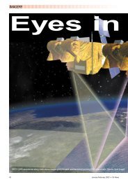
by Gordon Petrie<br />
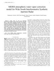
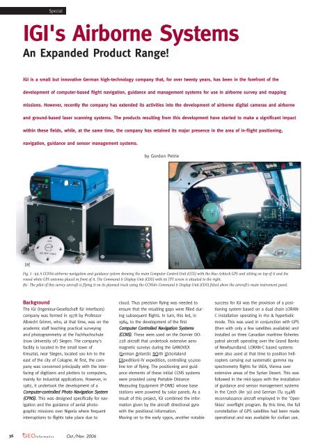
Fig. 1 - (a) A CCNS4 airborne navigation and guidance system showing the main Computer Control Unit (CCU) with the blue Ashtech GPS unit sitting on top <strong>of</strong> it and the<br />
round white GPS antenna placed in front <strong>of</strong> it. The Command & Display Unit (CDU) with its TFT screen is situated to the right.<br />
(b) - The pilot <strong>of</strong> this survey aircraft is flying it on its planned track using the CCNS4's Command & Display Unit (CDU) fitted above the aircraft's main instrument panel.<br />
[b]<br />
cloud. Thus precision flying was needed to<br />
ensure that the resulting gaps were filled during<br />
subsequent flights. In turn, this led, in<br />
1984, to the development <strong>of</strong> the first<br />
CCoommppuutteerr CCoonnttrroolllleedd NNaavviiggaattiioonn SSyysstteemmss<br />
((CCCCNNSS)). These were used on the Dornier DO-<br />
228 aircraft that undertook extensive aeromagnetic<br />
surveys during the GANOVEX<br />
(German Antarctic NOrth Victorialand<br />
EXpedition)-IV expedition, controlling 50,000<br />
line km <strong>of</strong> flying. The positioning and guidance<br />
elements <strong>of</strong> these initial CCNS systems<br />
were provided using Portable Distance<br />
Measuring Equipment (P-DME) whose base<br />
stations were powered by solar panels. As a<br />
result <strong>of</strong> this project, IGI combined the information<br />
given by the aircraft directional gyro<br />
with the positional information.<br />
Moving on to the early 1990s, another notable<br />
success for IGI was the provision <strong>of</strong> a positioning<br />
system based on a dual chain LORAN-<br />
C installation operating in rho & hyperbolic<br />
mode. This was used in conjunction with GPS<br />
(then with only a few satellites available) and<br />
installed on three Canadian maritime fisheries<br />
patrol aircraft operating over the Grand Banks<br />
<strong>of</strong> Newfoundland. LORAN-C based systems<br />
were also used at that time to position helicopters<br />
carrying out systematic gamma ray<br />
spectrometry flights for IAEA, Vienna over<br />
extensive areas <strong>of</strong> the Syrian Desert. This was<br />
followed in the mid-1990s with the installation<br />
<strong>of</strong> guidance and sensor management systems<br />
in the Czech (An 30) and German (Tu 154M)<br />
reconnaissance aircraft employed in the 'Open<br />
Skies' overflight program. By this time, the full<br />
constellation <strong>of</strong> GPS satellites had been made<br />
operational and was available for civilian use.
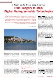
Fig. 2 - (a) An AEROcontrol-IId system with the integrated DGPS/IMU unit housed in the red box on the left while the<br />
computer and data storage unit is on the right with the white round GPS antenna sitting on top <strong>of</strong> it.<br />
(b) - The diagram shows the AEROcontrol lever arm correction that relates the position <strong>of</strong> the GPS antenna to the<br />
projection centre <strong>of</strong> the aerial camera.<br />
In 1992/93, five CCNS systems equipped with<br />
GPS receivers were supplied to the Hansa<br />
Luftbild mapping company and, in 1998, an<br />
aircraft engaged on minefield detection in<br />
Mozambique was equipped with a CCNS that<br />
obtained its positional information from the<br />
wide-area OOmmnniiSSTTAARR differential GPS service<br />
using satellite broadcast technology. From<br />
then on, the CCNS systems have relied almost<br />
exclusively on GPS and aircraft directional<br />
gyro technology for their positional information<br />
and automatic drift/crab correction. In<br />
1996, IGI also introduced its AAEERROOccoonnttrrooll unit<br />
as an optional addition to its CCNS4 system.<br />
This utilizes an integrated GPS/IMU system to<br />
measure the position and attitude <strong>of</strong> an airborne<br />
camera at the instant <strong>of</strong> the exposure<br />
<strong>of</strong> its image. The resulting data can be used<br />
as exterior orientation data when carrying out<br />
an aerial triangulation to provide control for<br />
Latest News? Visit www.geoinformatics.com<br />
[a]<br />
[b]<br />
mapping or, in suitable situations, for the<br />
direct georeferencing <strong>of</strong> the camera images.<br />
Mission Planning<br />
An obvious requirement for systems such as<br />
CCNS is the provision <strong>of</strong> suitable s<strong>of</strong>tware that<br />
will allow precise flight planning to be carried<br />
out prior to the actual mission being flown.<br />
This will include the drawing <strong>of</strong> the proposed<br />
flight lines overlaid on a suitable background<br />
map and the entry <strong>of</strong> suitable waypoints,<br />
exclusion zones, hazards and other important<br />
navigation features. Originally IGI provided a<br />
DOS-based s<strong>of</strong>tware package, WWWWMMPP (=<br />
World Wide Mission Planning) complete with a<br />
tablet digitizer and graphics plotter for the<br />
purpose. However this has been superseded<br />
by Windows-based s<strong>of</strong>tware, called WWiinnMMPP<br />
(= Windows-based Mission Planning). This can<br />
accept digital map data in numerous raster or<br />
vector formats and from different sources,<br />
including data from Google Earth. The flight<br />
planning can be carried out using either<br />
Lat/Long geographic coordinates or a local<br />
(national) rectangular coordinate system. If<br />
available, DTM data can also be utilized in the<br />
flight planning. The WinMP s<strong>of</strong>tware creates<br />
optimal flight line patterns and exposure positions<br />
for different airborne imagers with specified<br />
overlaps both for blocks (areas) and for<br />
corridor-type applications (along rivers, canals,<br />
roads, railways, et cetera). The planned flight<br />
data that has been prepared using WinMP is<br />
then automatically transformed to WGS84 coordinates<br />
and stored on a PC-card for insertion<br />
into the CCNS system. This combination <strong>of</strong><br />
WinMP and CCNS4 allows photos to be taken<br />
at the planned position within metres and to<br />
repeat them later with the same accuracy.<br />
CCNS4<br />
This is the current version <strong>of</strong> the CCNS system<br />
and comprises a central computer unit ((CCCCUU))<br />
and a command and display unit ((CCDDUU)) fitted<br />
with a small (5 inch or 9 inch) TFT screen.<br />
These two units are equipped with standard<br />
aircraft interfaces and connectors to facilitate<br />
their installation in a wide variety <strong>of</strong> aircraft.<br />
The CCNS4 system is designed to be operated<br />
in conjunction with all commonly used airborne<br />
film and digital cameras, pushbroom<br />
line scanners and laser scanners. The system<br />
gets its positional information (and speed)<br />
from a GPS receiver that is normally mounted<br />
inside the CCU and can be optimized for realtime<br />
differential GPS operation via OmniSTAR.<br />
Information about the aircraft heading can be<br />
obtained from the aircraft's directional gyro if<br />
this is available. If the optional AEROcontrol<br />
unit has been fitted, then the directional information<br />
is obtained from the IMU and utilized<br />
directly by the CCNS system. This possibility<br />
allows the automatic drift setting <strong>of</strong> the camera<br />
or scanner mount.<br />
A distinctive feature <strong>of</strong> the CCNS system is its<br />
CDU, which is designed to look like and to<br />
operate in the same way as other standard<br />
aircraft instruments. The operation <strong>of</strong> the CDU<br />
is controlled using a set <strong>of</strong> knobs and buttons<br />
(similar to those used in modern cockpit<br />
instrumentation) and the information derived<br />
from the CCU is displayed on the TFT screen in<br />
a typical EFIS (Electronic Flight Information<br />
System) format. Thus the main part <strong>of</strong> the<br />
CDU screen displays information on the flight<br />
track in graphical form. The pilot can observe<br />
the actual flight track being plotted continuously<br />
in real time against the planned track.<br />
This allows him to make the appropriate corrections<br />
to enable the planned flight lines to<br />
be implemented. Along the side <strong>of</strong> the display,<br />
Oct./Nov. 2006<br />
Special<br />
37
[a]<br />
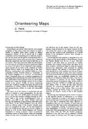
Fig. 3 - (a) The DigiCAM-H airborne digital camera is shown as a complete unit at top left.<br />
The individual components <strong>of</strong> the camera comprising (from left to right) the Imacon digital<br />
back, the modified Hasselblad camera body and the lens are shown in the lower right part<br />
<strong>of</strong> the picture.<br />
(b) Two DigiCAM-H cameras are shown mounted side-by-side in a cylindrical box that fits<br />
into a SOMAG GSM3000 gyro-controlled camera mount. The AEROcontrol DGPS/IMU unit<br />
sits on a small shelf mounted above the two cameras.<br />
auxiliary data from the aircraft's other instruments<br />
or from the airborne sensors that the<br />
CCNS system is controlling are displayed continuously<br />
in numerical form. If needed, the<br />
CCNS4 system can control the operation <strong>of</strong><br />
two devices, e.g. two cameras <strong>of</strong> different<br />
makes and models or a camera and a laser<br />
scanner, simultaneously. In total, more than<br />
250 CCNS systems are currently in operational<br />
use for flight control and management purposes<br />
world-wide.<br />
AEROcontrol<br />
The AEROcontrol GPS/IMU unit was developed<br />
for the accurate measurement <strong>of</strong> the position<br />
and attitude <strong>of</strong> the aerial camera at the precise<br />
moment <strong>of</strong> exposure <strong>of</strong> each individual<br />
[a]<br />
[b]<br />
image as required for Direct Georeferencing<br />
(DG). It first appeared in 1996. The IMU comprises<br />
three accelerometers and three gyroscopes<br />
together with their associated electronics.<br />
These components are mounted in a<br />
single compact block within a metal box that<br />
is attached directly to the airborne camera.<br />
Initially the IMUs used dry-tuned gyros, but<br />
with the introduction <strong>of</strong> the AAEERROOccoonnttrrooll--IIIIdd<br />
model in the year 2000, fibre-optic gyros<br />
(FOGs) have been used instead. These IMUs<br />
are manufactured in Germany and are therefore<br />
subject to German licensing regulations<br />
regarding their export. The AEROcontrol system<br />
can be operated using various types <strong>of</strong> highperformance<br />
dual-frequency GPS receivers,<br />
installed either internally inside the<br />
AEROcontrol computer/storage box or as an<br />
external receiver. In many cases, 12-channel<br />
L1/L2 Ashtech or NovAtel units have been supplied<br />
to customers. Now receivers are available<br />
to receive signals from the GLONASS and<br />
Galileo satellites as well as the usual GPS<br />
satellites.<br />
The complete AEROcontrol unit also includes a<br />
computer unit that collects and stores the<br />
measured data from the IMU and the GPS<br />
receiver on a PC-card for later post-processing<br />
operations. A real-time computation allows the<br />
collected data to be used in-fight as navigation<br />
data by the CCNS4 unit. The AEROcontrol<br />
can either be operated as a stand-alone system<br />
or be operated by the CCNS. The CCNS4<br />
and the AEROcontrol computer can be supplied<br />
either as separate devices or they can be<br />
integrated together in a single rack. A combined<br />
CCNS/AEROcontrol system is also available<br />
linked to an OmniSTAR-HP (High<br />
Oct./Nov. 2006<br />
Special<br />
Fig. 4 - (a) This LiteMapper airborne laser scanning system is mounted on a purpose-built antivibration<br />
platform. The Riegl laser is the large white box sitting at the back with the<br />
AEROcontrol unit placed alongside in front <strong>of</strong> it.<br />
(b) A helicopter fitted with a specially-built Helipod box containing the LiteMapper system.<br />
[b]<br />
39
Special<br />
Precision) system, which means that the exterior<br />
orientation (position and attitude) parameters<br />
are then available prior to the aircraft<br />
landing. Currently there are more than 70<br />
AEROcontrol units in operation. Most <strong>of</strong><br />
Vexcel's UltraCam airborne digital cameras<br />
have been supplied with CCNS/AEROcontrol<br />
units. Several other units have been supplied<br />
for use with Intergraph DMC airborne digital<br />
cameras.<br />
AERO<strong>of</strong>fice<br />
Just as there is a need for flight planning s<strong>of</strong>tware<br />
(WinMP) prior to an actual mission, so<br />
there is a need for s<strong>of</strong>tware to carry out the<br />
post-processing <strong>of</strong> the data that has been<br />
measured and collected by the AEROcontrol<br />
DGPS/IMU system. This is provided by IGI in<br />
the form <strong>of</strong> its AERO<strong>of</strong>fice s<strong>of</strong>tware. This<br />
Windows-based package provides tools for<br />
handling the measured data and subsequently<br />
processing it. The s<strong>of</strong>tware includes a Kalman<br />
filter that acts as the core for the computation<br />
<strong>of</strong> the combined GPS/IMU data and the<br />
GGrraaffNNaavv s<strong>of</strong>tware package from the Waypoint<br />
division <strong>of</strong> NovAtel in Canada to process the<br />
DGPS data. Additional programs carry out the<br />
transformation <strong>of</strong> the resulting exterior orientation<br />
elements into the local mapping coordi-<br />
nate system.<br />
AERO<strong>of</strong>fice also<br />
incorporates a<br />
special customized<br />
version <strong>of</strong> the<br />
BBIINNGGOO aerial triangulation<br />
s<strong>of</strong>tware<br />
from the GIP company.<br />
This features<br />
a reduced capacity<br />
<strong>of</strong> 30 stereo-models<br />
instead <strong>of</strong> the<br />
thousands that<br />
may be used in<br />
aerial triangulation.<br />
This BINGO-30 program allows the precise<br />
bore-sighting <strong>of</strong> the camera system over a<br />
selected sub-part <strong>of</strong> the flown block for use in<br />
direct geo-referencing operations.<br />
Fig. 5 - A Digital Surface Model (DSM) <strong>of</strong> an area near Arfeld in North-Rhine Westphalia,<br />
Germany produced from the data acquired by a LiteMapper 2800 airborne laser scanning<br />
system.<br />
[a]<br />
DigiCAM<br />
At the technical exhibition <strong>of</strong> the ISPRS<br />
Congress held in Istanbul in 2004, IGI introduced<br />
the DDiiggiiCCAAMM--KK//1144 medium-format airborne<br />
digital camera based on the Kodak DCS<br />
Pro 14n SLR (producing a 14 megapixel color<br />
image). After the first sales <strong>of</strong> this type <strong>of</strong><br />
camera, Kodak decided to withdraw completely<br />
from the pr<strong>of</strong>essional camera market in<br />
2005 and ceased to manufacture its DCS Pro<br />
14n model - which caused difficulties to the<br />
several other system suppliers who had based<br />
their products on this camera, as well as IGI.<br />
Later on, IGI developed a 22 megapixel model<br />
named DDiiggiiCCAAMM--HH//2222. This model is based on<br />
a modified Hasselblad medium-format camera<br />
equipped with an Imacon digital back, Imacon<br />
having been bought by Hasselblad. The overall<br />
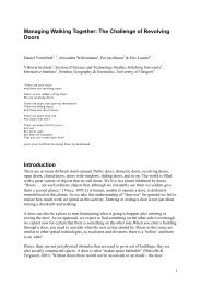
Fig. 6 - (a) A StreetMapper van equipped with laser<br />
scanners mounted on the vehicle's ro<strong>of</strong> rack.<br />
(b) Components <strong>of</strong> a StreetMapper system mounted on<br />
the ro<strong>of</strong> rack <strong>of</strong> a vehicle showing the laser scanners,<br />
TERRAcontrol DGPS/IMU unit and the GPS antenna.<br />
(c) The displays associated with<br />
the StreetMapper system<br />
mounted on the front facia<br />
(dash-board) <strong>of</strong> the van.<br />
[b]<br />
DigiCAM-H system comprises a calibrated camera<br />
system with its modular body, lens and 22<br />
megapixel digital back; the DDiiggiiCCoonnttrrooll computer;<br />
a so-called IImmaaggee BBaannkk for the storage<br />
<strong>of</strong> 850 exposed images; and an 8 inch TFT<br />
touch screen for monitoring and display purposes.<br />
A wide range <strong>of</strong> interchangeable lenses<br />
with different focal lengths (35mm to 300mm)<br />
is also available, allowing the acquisition <strong>of</strong><br />
either RGB or CIR images. A new DigiCAM<br />
model featuring a 39 megapixel digital back<br />
will be available soon and a large storage unit<br />
that can store more than 2500 images will be<br />
delivered with this camera. The touch screen<br />
acts as the user interface to the system, allowing<br />
the operator to view the exposed images<br />
as they are taken and to alter the exposure<br />
settings if required.<br />
The DigiCAM cameras can be triggered by a<br />
CCNS system in accordance with the preplanned<br />
flight lines and parameters that have<br />
been stored in the system. The camera can<br />
also be operated in conjunction with an<br />
AEROcontrol system to determine the exterior<br />
orientation parameters for each exposed<br />
image. Multiple DigiCAM systems can be operated<br />
within a specially designed cylindrical box<br />
that can sit within a standard gyro-controlled<br />
aerial camera mount such as the SOMAG GSM-<br />
3000, Leica PAV30 or Intergraph T-AS. If<br />
images have to be exposed at intervals <strong>of</strong> less<br />
than 2.5 seconds, two DigiCAMs can be placed<br />
side-by-side and operated to fire alternately.<br />
Indeed up to five DigiCAMs can be accommodated<br />
within the cylindrical adapter box.<br />
[c]
LiteMapper<br />
IGI also entered the field <strong>of</strong> airborne laser scanning<br />
in 2003. The basic hardware components<br />
<strong>of</strong> the system, called LiteMapper, comprise a<br />
laser scanning engine built by Riegl in Austria;<br />
the CCNS/AEROcontrol DGPS/IMU system discussed<br />
above; and a special LLMMccoonnttrrooll computer-based<br />
system to control the operation <strong>of</strong><br />
the laser scanner. The accompanying s<strong>of</strong>tware<br />
includes the WinMP and AERO<strong>of</strong>fice packages<br />
discussed above, together with LLMMttoooollss, developed<br />
by IGI for data registration and visualization<br />
purposes in-flight and LLaassTToooollss, developed<br />
by GeoLas for LiDAR geocoding, transformations<br />
and projections. The final LiDAR data processing<br />
and generation <strong>of</strong> DEMs is normally<br />
carried out using the TTeerrrraaSSccaann and<br />
TTeerrrraaMMooddeelleerr s<strong>of</strong>tware packages from the<br />
Finnish Terrasolid company.<br />
Initially LiteMapper was <strong>of</strong>fered with a choice<br />
<strong>of</strong> two models - LLiitteeMMaappppeerr 11440000 for low-altitude<br />
flights (up to 300m) from a helicopter<br />
aimed at corridor mapping; and LLiitteeMMaappppeerr<br />
22880000 for higher-altitude flights (up to 900m)<br />
from a fixed wing aircraft to provide wide-area<br />
mapping, including the recording <strong>of</strong> return signal<br />
intensity. These have been replaced respec-<br />
Latest News? Visit www.geoinformatics.com<br />
tively by the current models - the LLiitteeMMaappppeerr<br />
22440000 for low-altitude surveys (up to 450m) and<br />
the LLiitteeMMaappppeerr 55660000 for high-altitude surveys<br />
(up to 1,800m), including the recording <strong>of</strong> the<br />
full intensity waveform. Of course, the DigiCAM<br />
can be integrated into a LiteMapper system for<br />
the simultaneous collection <strong>of</strong> images and laser<br />
data. So far, six LiteMapper systems have been<br />
delivered to customers; more are currently<br />
under construction.<br />
StreetMapper<br />
IGI is a partner with the 3D Laser Mapping<br />
company from Nottingham in the U.K. in the<br />
recent development <strong>of</strong> the StreetMapper<br />
mobile mapping system that scans and maps<br />
roads, buildings, and trees from a moving van<br />
equipped with scanning lasers. The system<br />
comprises three (or more) lasers mounted on<br />
a ro<strong>of</strong> rack that are operated in conjunction<br />
with <strong>IGI's</strong> TTEERRRRAAccoonnttrrooll GPS/IMU unit (derived<br />
from its AEROcontrol unit) and the IGI s<strong>of</strong>tware<br />
and hardware solutions for the control <strong>of</strong> all<br />
laser scanners and data storage. IGI also contributes<br />
its TTEERRRRAAo<strong>of</strong>fffiiccee s<strong>of</strong>tware (derived from<br />
its AERO<strong>of</strong>fice package) for the processing <strong>of</strong><br />
the IMU data. The GrafNav s<strong>of</strong>tware is again<br />
used to process the DGPS data. Finally the<br />
Oct./Nov. 2006<br />
Special<br />
TerraScan/TerraModeler/TerraMatch suite <strong>of</strong> programs<br />
from Terrasolid is utilized for the processing<br />
<strong>of</strong> the laser scanner data and its transformation<br />
into the final 3D model data.<br />
Conclusion<br />
As can be seen from the above account, over<br />
the last ten years, IGI has developed steadily<br />
from its original status as a specialist supplier<br />
<strong>of</strong> computer-based flight planning, navigation<br />
and guidance systems for survey aircraft into a<br />
quite diversified company with a substantial<br />
range <strong>of</strong> high-tech products and systems for<br />
use in both airborne and ground-based mapping<br />
applications.<br />
Gordon Petrie (g.petrie@geog.gla.ac.uk) is Emeritus<br />
Pr<strong>of</strong>essor in the Dept. <strong>of</strong> Geographical & Earth<br />
Sciences,<strong>University</strong> <strong>of</strong> <strong>Glasgow</strong>, Scotland, U.K. Web<br />
Pages - http://web.ges.gla.ac.uk/~gpetrie/. Further<br />
information on <strong>IGI's</strong> products can be obtained from<br />
the company's Web site www.igi-systems.com/ and<br />
from the special Web sites www.litemapper.com/ and<br />
www.streetmapper.net/ that have been set up for these<br />
two products.<br />
41