1N5719 DS Avago - SmartData
1N5719 DS Avago - SmartData
1N5719 DS Avago - SmartData

You also want an ePaper? Increase the reach of your titles
YUMPU automatically turns print PDFs into web optimized ePapers that Google loves.
<strong>1N5719</strong>, 1N5767, 5082-3001, 5082-3039,<br />
5082-3077, 5082-3080/81, 5082-3188, 5082-3379<br />
PIN Diodes for RF Switching and Attenuating<br />
Data Sheet<br />
Description/Applications<br />
These general purpose switching diodes are intended<br />
for low power switching applications such as RF<br />
duplexers, antenna switching matrices, digital phase<br />
shifters, and time multiplex filters. The 5082-3188 is<br />
optimized for VHF/UHF bandswitching.<br />
The RF resistance of a PIN diode is a function of the<br />
current flowing in the diode. These current controlled<br />
resistors are specified for use in control applications<br />
such as variable RF attenuators, automatic gain control<br />
circuits, RF modulators, electrically tuned filters,<br />
analog phase shifters, and RF limiters.<br />
Outline 15 diodes are available on tape and reel. The<br />
tape and reel specification is patterned after RS-296-D.<br />
Maximum Ratings<br />
Junction Operating and<br />
Storage Temperature Range ............... -65°C to +150°C<br />
Power Dissipation 25°C .................................... 250 mW<br />
(Derate linearly to zero at 150°C)<br />
Peak Inverse Voltage (PIV)....................... same as VBR<br />
Maximum Soldering Temperature ...... 260°C for 5 sec<br />
Features<br />
• Low Harmonic Distortion<br />
• Large Dynamic Range<br />
• Low Series Resistance<br />
• Low Capacitance<br />
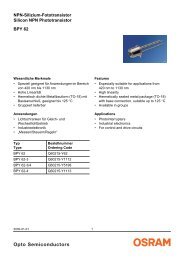
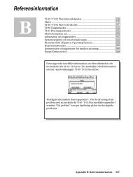
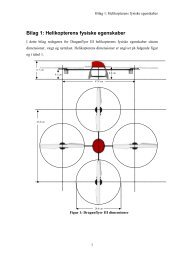
Outline 15<br />
0.41 (.016)<br />
0.36 (.014)<br />
1.93 (.076)<br />
1.73 (.068)<br />
CATHODE<br />
25.4 (1.00)<br />
MIN.<br />
4.32 (.170)<br />
3.81 (.150)<br />
25.4 (1.00)<br />
MIN.<br />
DIMENSIONS IN MILLIMETERS AND (INCHES).
Mechanical Specifications<br />
The <strong>Avago</strong> Outline 15 package has a glass hermetic seal<br />
with dumet leads. The lead finish is 95-5 tin-lead (SnPb)<br />
for all PIN diodes. The leads on the Outline 15 package<br />
should be restricted so that the bend starts at least<br />
General Purpose Diodes<br />
Electrical Specifications at T A = 25°C<br />
2<br />
1/16 inch (1.6 mm) from the glass body. Typical package<br />
inductance and capacitance are 2.5 nH and 0.13 pF,<br />
respectively. Marking is by digital coding with a cathode<br />
band.<br />
Maximum Minimum Maximum<br />
Part Total Breakdown Residual Series Effective Carrier Reverse Recovery<br />
Number Capacitance Voltage Resistance Lifetime Time<br />
5082- CT (pF) VBR (V) RS (Ω) τ (ns) trr (ns)<br />
General Purpose Switching and Attenuating<br />
3001 0.25 200 1.0 100 (min.) 100 (typ.)<br />
3039 0.25 150 1.25 100 (min.) 100 (typ.)<br />
<strong>1N5719</strong> 0.3** 150 1.25 100 (min.) 100 (typ.)<br />
3077<br />
Band Switching<br />
0.3 200 1.5 100 (min.) 100 (typ)<br />
3188 1.0* 35 0.6** 70 (typ.)* 12 (typ.)<br />
Test VR = 50 V VR = VBR IF =100 mA IF = 50 mA IF = 20 mA<br />
Conditions *VR = 20 V Measure *IF = 20 mA IR = 250 mA VR = 10 V<br />
**VR = 100 V IR ≤ 10 µA **IF = 10 mA *IF = 10 mA 90% Recovery<br />
f = 1 MHz f = 100 MHz *IR = 6 mA<br />
Notes:<br />
Typical CW power switching capability for a shunt switch in a 50Ω system is 2.5 W.<br />
RF Current Controlled Resistor Diodes<br />
Electrical Specifications at T A = 25°C<br />
Max.<br />
Max. High Low Difference<br />
Effective Min. Residual Max. Resistance Resistance in<br />
Carrier Breakdown Series Total Limit, R H (Ω) Limit, R L (Ω) Resistance<br />
Part Lifetime Voltage Resistance Capacitance vs. Bias<br />
Number τ (ns) V BR (V) R S (W) C T (pF) Min. Max. Min. Max. Slope, Dc<br />
5082-3080 1300 (typ.) 100 2.5 0.4 1000 8**<br />
1N5767* 1300 (typ.) 100 2.5 0.4 1000 8**<br />
5082-3379 1300 (typ.) 50 0.4 8**<br />
5082-3081 2500 (typ.) 100 3.5 0.4 1500 8**<br />
Test<br />
Conditions<br />
IF = 50 mA<br />
IR = 250 mA<br />
VR = VBR, Measure<br />
IR ≤ 10 µA<br />
IF = 100 mA<br />
f = 100 MHz<br />
VR = 50 V<br />
f = 1 MHz<br />
IF = 0.01 mA<br />
f = 100 MHz<br />
IF = 1.0 mA<br />
IF = 20 mA**<br />
f = 100 MHz<br />
Batch<br />
Matched at<br />
IF = 0.01 mA<br />
and 1.0 mA<br />
f = 100 MHz<br />
*The 1N5767 has the additional specifications: τ = 1.0 msec minimum<br />
IR = 1 µA maximum at VR = 50 V<br />
VF = 1 V maximum at IF = 100 mA.
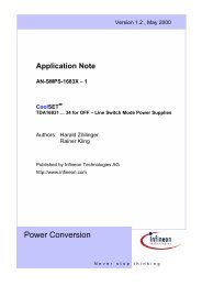
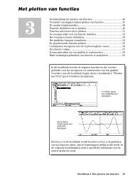
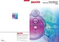
Typical Parameters at T A = 25°C (unless otherwise noted)<br />
I F – FORWARD CURRENT (mA)<br />
CAPACITANCE (pF)<br />
BELOW FIRST ORDER (dB)<br />
100<br />
10<br />
1<br />
0.1<br />
5082-3001, 3039,<br />
3077, 3080<br />
IN5719<br />
125°C<br />
25°C<br />
–60°C<br />
0.01 0 0.2 0.4 0.6 0.8 1.0 1.2<br />
V F – FORWARD VOLTAGE (V)<br />
Figure 1. Forward Current vs.<br />
Forward Voltage.<br />
1.0<br />
.5<br />
0<br />
0 10 20 30 40 50 60 70<br />
REVERSE VOLTAGE (V)<br />
Figure 4. Typical Capacitance vs.<br />
Reverse Voltage.<br />
0<br />
20<br />
40<br />
60<br />
80<br />
5082-3039<br />
IN5719<br />
5082-3001<br />
10 dB Bridged Tee Attenuator<br />
40 dB mV Output Levels<br />
One Input Frequency Fixed 100 MHz<br />
5082-3080<br />
5082-3379<br />
5082-3081<br />
100<br />
0 10 20 30 40 50 60 70 80<br />
FREQUENCY (MHz)<br />
Figure 7. Typical Second Order<br />
Intermodulation Distortion.<br />
RF RESISTANCE (OHMS)<br />
CAPACITANCE (pF)<br />
BELOW FIRST ORDER (dB)<br />
10,000<br />
1000<br />
100<br />
10<br />
1<br />
5082-3001<br />
5082-3039<br />
5082-3077<br />
IN5719<br />
0.1<br />
0.001 0.01 0.1 1 10 100<br />
I F – FORWARD BIAS CURRENT (mA)<br />
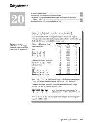
Figure 2. Typical RF Resistance vs.<br />
Forward Bias Current.<br />
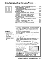
2.5<br />
2.0<br />
1.5<br />
1.0<br />
5082-3188<br />
.5<br />
0<br />
5082-3080<br />
5082-3081<br />
5082-3379<br />
0 10 20 30 40 50 60 70<br />
REVERSE VOLTAGE (V)<br />
Figure 5. Typical Capacitance vs.<br />
Reverse Voltage.<br />
10<br />
20<br />
30<br />
40<br />
50<br />
60<br />
PIN Diode Cross Modulation<br />
10 dB Bridged Tee Attenuator<br />
Unmodulated Frequency 100 MHz<br />
100% Modulation 15 kHz<br />
40 dB mV Output Levels<br />
5082-3080<br />
5082-3379<br />
70<br />
5082-3081<br />
80<br />
0 10 20 30 40 50 60 70 80<br />
MODULATED FREQUENCY (MHz)<br />
Figure 8. Typical Cross Intermodulation<br />
Distortion.<br />
RF RESISTANCE (OHMS)<br />
3<br />
100,000<br />
REVERSE RECOVERY TIME (ns)<br />
10,000<br />
1000<br />
100<br />
10<br />
5082-3081<br />
5082-3080<br />
5082-3379<br />
1<br />
0.001 0.01 0.1 1 10 100<br />
IF – FORWARD BIAS CURRENT (mA)<br />
Figure 3. Typical RF Resistance vs.<br />
Forward Bias Current.<br />
1000<br />
100<br />
5082-3001<br />
3039<br />
3077<br />
IN5719<br />
VR = 5V<br />
VR = 10V<br />
VR = 20V<br />
10<br />
0 10 20 30<br />
FORWARD CURRENT (mA)<br />
Figure 6. Typical Reverse Recovery Time<br />
vs. Forward Current for Various Reverse<br />
Driving Voltages.
Diode Package Marking<br />
1N5xxx 5082-xxxx<br />
would be marked:<br />
1Nx xx<br />
xxx xx<br />
YWW YWW<br />
where xxxx are the last four digits of the 1Nxxxx or the 5082-xxxx part<br />
number. Y is the last digit of the calendar year. WW is the work week of<br />
manufacture.<br />
Examples of diodes manufactured during workweek 45 of 1999:<br />
1N5712 5082-3080<br />
would be marked:<br />
1N5 30<br />
712 80<br />
945 945<br />
Part Number Ordering Information<br />
Part Number No. of devices Container<br />
5082-3xxx#T25/1N57xx#T25 2500 Tape & Reel<br />
5082-3xxx#T50/ 1N57xx#T50 5000 Tape & Reel<br />
5082-3xxx/ 1N57xx 100 Antistatic bag<br />
For product information and a complete list of distributors, please go to our web site:<br />
www.avagotech.com<br />
<strong>Avago</strong>, <strong>Avago</strong> Technologies, and the A logo are trademarks of <strong>Avago</strong> Technologies, Pte.<br />
in the United States and other countries.<br />
Data subject to change. Copyright © 2006 <strong>Avago</strong> Technologies Pte. All rights reserved.<br />
Obsoletes 5968-7182EN<br />
5989-3339EN March 31, 2006