Powder Diffraction - Spallation Neutron Source
Powder Diffraction - Spallation Neutron Source
Powder Diffraction - Spallation Neutron Source

Create successful ePaper yourself
Turn your PDF publications into a flip-book with our unique Google optimized e-Paper software.
A Very Abbreviated Introduction<br />
to <strong>Powder</strong> <strong>Diffraction</strong><br />
Brian H. Toby
Outline<br />
Where to go for more information<br />
What can we learn from powder diffraction?<br />
Some background on crystallography<br />
<strong>Diffraction</strong> from single crystals<br />
<strong>Diffraction</strong> from powders<br />
Instruments for powder diffraction collection<br />
Materials effects in powder diffraction<br />
Crystallographic analysis of powder diffraction data<br />
(Total scattering/PDF analysis)<br />
2
Where to go for more…<br />
There are many texts available. My favorites:<br />
Fundamentals of Crystallography (2nd Ed.),<br />
Carmelo Giacovazzo, et al. (Oxford, 2002, ~$90)<br />
[Modern & very comprehensive, quite reasonable price<br />
considering quality, size & scope.]<br />
X-Ray Structure Determination: A<br />
Practical Guide (2nd Ed.), G. H. Stout, &<br />
L. H. Jensen (Wiley, 1989, ~$150) [Focused<br />
on small-molecule single crystal techniques, dated,<br />
but very easy to read; very good explanations of<br />
fundamentals. 1 st book for many in field.]<br />
APS Web lectures on powder diffraction crystallography:<br />
www.aps.anl.gov: look for Education/Schools/<strong>Powder</strong> <strong>Diffraction</strong> Crystallography<br />
(http://www.aps.anl.gov/Xray_Science_Division/<strong>Powder</strong>_<strong>Diffraction</strong>_Crystallography)<br />
Intended to introduce Rietveld refinement techniques with GSAS & EXPGUI<br />
3
Why do we do powder diffraction?<br />
Learn where the atoms are (single crystals are better for this, when<br />
available)<br />
Determine the phase(s) in a sample<br />
Measure lattice constants<br />
Quantify the components of a mixture<br />
Learn about physical specimen characteristics such as stress, preferred<br />
orientation or crystallite sizes<br />
Occupancies of elements amongst crystallographic sites<br />
4
Basic Crystallography<br />
5
The Lattice<br />
Crystals are constructed from repeated arrangements of atoms.<br />
Crystalline structure can be described as set of “identical boxes”<br />
stacked in 3D; the contents of each box is identical (exception:<br />
quasicrystals)<br />
– A lattice is a mathematical concept where each lattice point describes an<br />
identical environment; lattice points are the corners of the “identical boxes.”<br />
Commonly used phrases<br />
such as “lattice compound”<br />
or “interstitials in the lattice”<br />
misuse the concept of a<br />
lattice.<br />
6
Lattice planes<br />
General Indices: lattice planes are indexed by the inverse of where they<br />
cut each axis:<br />
– Intercept of 0.5 index=2<br />
– Intercept of (|| to axis) index=0<br />
Related concept: Miller indices<br />
– used for crystal faces<br />
– Contain no common factors<br />
Notation: [ ] defines a direction<br />
– [100] is along a axis<br />
7
Single Crystal <strong>Diffraction</strong><br />
8
<strong>Diffraction</strong> from single crystals<br />
<strong>Diffraction</strong> occurs when the reciprocal lattice planes of a crystal are<br />
aligned at an angle with respect to the beam and the wavelength of an<br />
incident beam satisfies:<br />
– n 2 d sin (or better, 4 sin / Q) [Bragg’s Law]<br />
– d = 1/|d*| = 1/|ha* + kb* + lc*|<br />
9
Single Crystal <strong>Diffraction</strong> Intensities<br />
The Intensity of a diffracted beam, I hkl is related to a complex quantity<br />
called the structure factor, F hkl<br />
– I hkl |F hkl| 2<br />
The structure factor is determined by summing over all atoms in the<br />
crystal:<br />
– F hkl f i exp[2i(hx i + ky i + lz i)] exp(-U iQ 2 /2)<br />
Since adding multiples of 1 to x i,y i or z i does not change the above, the sum<br />
can be simplified to include only the atoms of one unit cell<br />
– f i represents the scattering power of an atom (also used, b i)<br />
– U i represents the average displacement of an atom from its ideal site<br />
10
<strong>Powder</strong> <strong>Diffraction</strong><br />
11
<strong>Diffraction</strong> from random polycrystalline material<br />
In a sufficiently large, randomly<br />
oriented polycrystalline sample<br />
(e.g. a powder) contains a very<br />
large number of crystallites.<br />
A beam impinging on the sample<br />
will find a representative number<br />
of crystallites in the right<br />
orientation for diffraction<br />
<strong>Diffraction</strong> occurs only at specific<br />
angles, those where Bragg’s Law is<br />
satisfied.<br />
Incident<br />
Beam<br />
Diffracted<br />
Beam<br />
12
Bragg cones in powder diffraction<br />
Since there is a random distribution of<br />
crystals then diffraction occurs in all<br />
directions for each Bragg angle, 2,<br />
thus powder diffraction arises in cones<br />
Beam<br />
All reflections occurring at a single 2<br />
value (as well as reflections at nearly<br />
the same value) are superimposed<br />
and only the sum of their intensities<br />
can be measured. For this reason a<br />
powder diffraction pattern gives less<br />
information than a single crystal<br />
measurement<br />
13
<strong>Diffraction</strong> of X-rays versus <strong>Neutron</strong>s<br />
14
Coherent Atomic Scattering Power (diffraction)<br />
Structure factors: F hkl = n f i exp[2i(hx i + ky i + lz i)] exp(-U iQ 2 /2)<br />
<strong>Diffraction</strong> Intensity: I hkl |F hkl| 2<br />
X-rays: The scattering power (form<br />
factor, f i) of an atom depends on the<br />
number of electrons in the atom and<br />
Q (Qsin/)<br />
<strong>Neutron</strong>s: The scattering power<br />
(scattering length, b i) of an atom<br />
depends on the isotope and is<br />
independent of Q<br />
– A few isotopes scatter with opposite<br />
phase to most, for these we write f (b)<br />
as negative<br />
– Magnetic scattering is from electrons;<br />
f M(Q) similar to x-rays<br />
Q or sin/, Å -1<br />
15
Comparison of <strong>Neutron</strong> and X-ray Atomic<br />
Scattering Powers<br />
16
Resonant Conditions<br />
X-rays<br />
X-ray form factor has in fact three<br />
components:<br />
f(Q) + f’(λ) + i f”(λ)<br />
– f is determined by Q and the number<br />
of electrons in an atom and is<br />
independent of wavelength<br />
– f’ and f” are small except at<br />
wavelengths very close to an atom’s<br />
absorption edge<br />
At wavelengths close to an edge<br />
absorption becomes high;<br />
fluorescence occurs above the edge.<br />
Experiments are sometimes performed<br />
at wavelengths close to absorption<br />
edges to enhance the scattering from<br />
particular elements<br />
<strong>Neutron</strong>s<br />
Scattering lengths for most atoms are<br />
wavelength-independent.<br />
A few isotopes (mostly lanthanides and<br />
actinides) have adsorption edges at<br />
accessible wavelengths.<br />
This can be a problem with higher<br />
energy neutrons<br />
Some atoms scatter incoherently;<br />
Hydrogen (not deuterium) has a huge<br />
incoherent scattering cross-section<br />
that tends to overpower coherent<br />
scattering unless H is less than a few<br />
atom %<br />
18
Types of <strong>Powder</strong> <strong>Diffraction</strong><br />
Measurements<br />
19
Measuring powder diffraction<br />
Angular dispersion: a single detector is moved<br />
over a range of 2 angles.<br />
– Sample irradiated with monochromatic radiation<br />
20
Area Detection<br />
With an area detector, a complete powder diffraction pattern can be<br />
collected in a fraction of a second.<br />
– Fast<br />
– Medium resolution<br />
– High background<br />
21
Highest resolution requires high collimation. Optimal is a crystal<br />
analyzer between the sample and detector: 11-BM Diffractometer<br />
Huber 480 rotation stage:<br />
high precision (~0.35arcsec)<br />
high accuracy (~1arcsec)<br />
slew or step scans<br />
12 analyzer array<br />
Si(111) crystals<br />
LaCl 3 scintillator detectors<br />
2° apart in 2Θ.<br />
beam<br />
Mitsubishi robot<br />
custom “fingers”<br />
Complete pattern is<br />
measured in
Reactor <strong>Source</strong> <strong>Neutron</strong> <strong>Diffraction</strong>
<strong>Powder</strong> Instruments: Constant Wavelength<br />
d/d (%)<br />
2.0<br />
1.8<br />
1.6<br />
1.4<br />
1.2<br />
1.0<br />
0.8<br />
0.6<br />
0.4<br />
High Resolution ( 12')<br />
High Intensity ( open)<br />
0.2<br />
0.0<br />
Ge(115)1.54 Å<br />
0 2 4 6 8<br />
Q =4sin (Å -1 )<br />
beamline HB2a at HFIR<br />
beamline BT1 at NIST (NCNR)
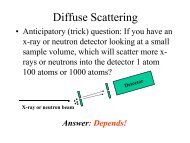
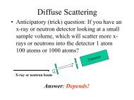
<strong>Spallation</strong> <strong>Source</strong>s<br />
A pulse of protons impacting the target produces a<br />
shower of fast neutrons that are slowed down in a<br />
moderator. A new pulse is created ~30 times/sec<br />
Intensity<br />
Intensity<br />
Time<br />
Energy<br />
Each pulse of<br />
neutrons contains<br />
a broad spectrum<br />
of neutron<br />
energies
Time of Flight <strong>Diffraction</strong><br />
Time of flight diffraction uses the fact that neutrons with different energies (velocities) have<br />
different wavelengths, =h/mv (de Broglies relationship)<br />
Protons into<br />
target<br />
Detector<br />
<strong>Neutron</strong>s<br />
to sample<br />
Detector
Time-of-flight (2dsin=)<br />
varies<br />
detector<br />
sample<br />
2<br />
fixed<br />
(Pulsed sources: e.g. SNS)
<strong>Neutron</strong> <strong>Powder</strong> <strong>Diffraction</strong> with <strong>Spallation</strong><br />
<strong>Source</strong><br />
<strong>Spallation</strong> source<br />
provides a broad<br />
band of wavelengths<br />
in sharp pulses<br />
– TOF detection<br />
allows<br />
measurement of<br />
intensity versus<br />
wavelength<br />
– Each detector<br />
provides a full<br />
diffraction pattern<br />
– Data collection<br />
times:<br />
• Seconds to<br />
hours<br />
NPDF instrument at LANSCE (Los Alamos)<br />
28
Understanding Materials Effects in<br />
<strong>Powder</strong> <strong>Diffraction</strong><br />
29
Materials effects on <strong>Powder</strong> <strong>Diffraction</strong><br />
Peak broadening:<br />
Crystallite size:<br />
– What happens when crystals become small?<br />
Residual Stress (Strain)<br />
– What happens if matrix effects do not allow crystallites to equilibrate lattice<br />
parameters?<br />
30
Crystallite Size Broadening<br />
The Fourier transform (FT) from<br />
an infinite array of regularly<br />
spaced objects is an array of<br />
delta functions.<br />
The FT from a finite length array<br />
is broadened.<br />
The finite sizes of crystallites will<br />
broaden all orders of reflections<br />
equally in units of Q ( d*)<br />
– differing reciprocal space<br />
directions may have differing<br />
amounts of broadening, if<br />
crystallites dimensions are<br />
not isotropic on average<br />
b*<br />
a*<br />
Crystallite Size Broadening can<br />
produce Lorentzian peak shapes<br />
(common) or Gaussian peak shapes<br />
(uncommon) or a combination of both.
Crystallite Size Broadening<br />
d*=constant<br />
See GSAS Manual, pp 158-167.<br />
GSAS fits crystallite broadening<br />
with two profile terms:<br />
• LX -> Lorentzian<br />
• GP -> Gaussian<br />
Relation between avg. size (p) and<br />
GSAS terms:<br />
p = 18000Kl<br />
pLX<br />
p = 18000Kl<br />
p GP<br />
K 1 (Scherrer constant, related to<br />
crystal shape)<br />
32
Microstrain Broadening<br />
When a material has residual<br />
stresses present, some crystallites<br />
are compressed. This must be<br />
balanced by other crystallites that<br />
are stretched (because ∑F=ma=0)<br />
This leads to a range of lattice<br />
constants.<br />
The spread between diffraction<br />
locations for the maximum and<br />
minimum lattice constant<br />
increases linearly with Q (∆Q/Q or<br />
∆d/d = constant)<br />
b*<br />
a*
Microstrain Broadening<br />
See GSAS Manual, pp 158-167.<br />
S =100% p<br />
18000<br />
GSAS fits strain broadening with two<br />
profile terms:<br />
• LY -> Lorentzian (most common)<br />
• GU -> Gaussian<br />
(note that GU also has an instrumental<br />
contribution)<br />
Relation between strain (as percentage) and GSAS terms:<br />
p<br />
LY S =100%<br />
18000 GU - GUI where GU I accounts for the instrumental contribution<br />
34
When Strain Differs by Reflection Class:<br />
“Anisotropic peak broadening”<br />
Strain may be anisotropic<br />
– think of a layered material where the layers can be pulled apart without<br />
much effort, but the layers themselves are quite “hard” (resistant to applied<br />
forces).<br />
– Such a material will be “squishy” in the layer direction and rigid in the other<br />
two (more broadening in the squishy direction.)<br />
Canonical anisotropic strain model: P. W. Stephens, Journal of Applied<br />
Crystallography 32, 281 (1999).<br />
– Restricts strain components in terms of 1st & 2nd-order terms allowed by<br />
lattice symmetry<br />
35
Anisotropic strain broadening terms<br />
36
Anisotropic strain broadening terms<br />
37
Fitting of <strong>Powder</strong> <strong>Diffraction</strong> Data<br />
(Rietveld Analysis)<br />
38
Why did Crystallography Revolutionize Science?<br />
1. Crystallography was the first scientific technique that provided direct<br />
information about molecular structure<br />
– Early work was intuitive: structures assigned based on patterns and<br />
symmetry (some results predate X-rays!)<br />
2. X-ray and neutron diffraction observations can be modeled very<br />
accurately directly when the molecular structure is known<br />
3. <strong>Diffraction</strong> can provide a very large number of independent observations<br />
– probability of finding an incorrect structure model that is both plausible and is<br />
in good agreement with the diffraction observations is very small (but not<br />
zero!)<br />
4. Computer-assisted least-squares optimization allows structural models<br />
to be improved, limited only by the quality of the data<br />
5. Statistical and brute-force techniques overcomes the incomplete nature<br />
of diffraction observations (direct methods vs. “the phase problem”).<br />
100+ years later, no other technique offers as much<br />
power for learning about molecular structure!<br />
39
Fitting crystallographic data -- what is it all about?<br />
We perform an experiment:<br />
– Get lots of intensity and position measurements in a diffraction<br />
measurement: what do they tell us?<br />
Obtain an unit cell that fits the diffraction positions (indexing)<br />
“Solve the structure”: determine an approximate model to match the<br />
intensities<br />
Add/modify the structure for completeness & chemical sense<br />
Optimize the structure (model) to obtain the best fit to the observed data<br />
– This is usually done with Gauss-Newton least-squares fitting<br />
– Parameters to be fit are structural and may account for other experimental<br />
effects<br />
Least Squares gives us a Hessian matrix; inverse is variance-covariance<br />
matrix which gives uncertainties in the parameters<br />
40
Crystallography from powder diffraction: before<br />
Rietveld<br />
How did crystallographers use powder diffraction data?<br />
Avoided powder diffraction<br />
Manually integrate intensities<br />
– discard peaks with overlapped reflections<br />
Or<br />
– rewrote single-crystal software to refine using sums of overlapped reflections<br />
Simulation of powder diffraction data was commonly done<br />
Qualitative reasoning: similarities in patterns implied similar structures<br />
Visual comparison between computed and observed structure verifies<br />
approximate model<br />
Fits, where accurate (& precise) models were rarely obtained<br />
Error propagation was difficult to do correctly (but not impossible)<br />
41
Hugo Rietveld’s technique<br />
Hugo Rietveld realized that if a pattern could be modeled, the fit<br />
between a computed pattern and observed data could be optimized.<br />
– Similar to single-crystal diffraction, except that now “experiment dependent<br />
parameters” must now be fit as well.<br />
• Background<br />
• Peak broadening<br />
• Lattice constants<br />
– Must have approximate model to start<br />
– Fewer data are available (usually)<br />
42
Calculation of <strong>Powder</strong> <strong>Diffraction</strong>: Graphical<br />
Example<br />
hkl<br />
hkl<br />
mult<br />
mult<br />
D-space<br />
d-space<br />
F<br />
Fobs hkl phase<br />
phase<br />
6,5,1 48 1.548 0.29 0<br />
7,3,2 48 1.548 1.709 180<br />
8,0,0 6 1.5236 29.45 0<br />
7,4,1 48 1.5004 2.327 0<br />
8,2,0 24 1.4781 3.703 0<br />
6,5,3 48 1.4569 1.27 0<br />
6,6,0 12 1.4365 0.242 180<br />
8,2,2 24 1.4365 2.086 0<br />
8,3,1 48 1.417 0.22 180<br />
7,4,3 48 1.417 1.827 180<br />
1) Generate reflection list<br />
2) Compute F hkl from<br />
model<br />
3) Peak heights are<br />
generated from<br />
|F hkl| 2 *multiplicity<br />
4) Convolute peaks & add<br />
background<br />
5) Optimize model, peak<br />
widths, etc. to improve<br />
fit<br />
43
Hugo Rietveld in the Petten Reactor (~1987)<br />
44
Single crystal fitting<br />
Minimize equation w i[y i - Y(x i,p)] 2 where<br />
Data: y i = F hkl (obs)<br />
Model: Y(x i,p) = F hkl (calc)<br />
Parameters (p 1, p 2, p 3… p m):<br />
atomic coordinates,<br />
displacement (T) factors<br />
<strong>Powder</strong> data fitting<br />
y i = observed powder diffraction<br />
intensities<br />
Y(x i,p) = computed diffraction<br />
intensities from (F hkl (calc),<br />
background model, profile<br />
convolution, preferred<br />
orientation correction…<br />
+ lattice parameters<br />
+ “experimental” parameters for<br />
peak shapes, background…<br />
45
Hugo Rietveld’s other breakthrough<br />
Based on intensities from the model, estimates for F hkl can be made,<br />
even when reflections are completely overlapped:<br />
Location 1:<br />
20% to A<br />
40% to B<br />
40% to C<br />
Location 2:<br />
100% to C<br />
1<br />
2<br />
measured<br />
simulated<br />
46
Rietveld Applications<br />
Crystallographic structure determination<br />
Quantify amounts of crystalline phases<br />
– (Amorphous content possible indirectly)<br />
Engineering properties<br />
– Residual stress/Crystallite sizes<br />
– Preferred orientation<br />
Lattice constant determination<br />
47
What sort of data are needed for Rietveld Analysis?<br />
Must be possible to fit peak shapes<br />
Q range and resolution demands dictated by structural complexity<br />
Data from lab instruments should be used with caution for structure<br />
determination<br />
<strong>Neutron</strong> data are usually necessary for occupancy determination<br />
48
Disadvantage of Rietveld:<br />
Many non-structural parameters need to be fit<br />
Background<br />
– fixed<br />
– functions<br />
Peak shape<br />
– “fundamental parameters”<br />
– functions<br />
Lattice constants<br />
– zero correction<br />
– flat plate terms<br />
Scaling<br />
– Phase fractions<br />
Structural parameters<br />
– atom positions<br />
– occupancies<br />
– displacement parameters<br />
Preferential Orientation<br />
Absorption<br />
<strong>Powder</strong> diffraction offers fewer observations and worse<br />
peak-to-background than single crystal diffraction<br />
49
Limitations of Rietveld<br />
Rietveld can only discern parameters that have effects on the<br />
powder diffraction pattern<br />
– Cannot separate some effects ever<br />
• Absolute configuration<br />
• Magnetic moment directions unless they break symmetry<br />
If two parameters have approximately the same effect on the<br />
powder diffraction pattern, they correlate and they cannot be<br />
differentiated (e.g. occupancies & displacement parameters)<br />
50
The physics that determine peak profiles<br />
Common factors<br />
Instrumental Resolution<br />
Axial Divergence (Low Angle<br />
Asymmetry)<br />
Sample placement/transparency<br />
Crystallite Broadening*<br />
Strain Broadening*<br />
* Note that these effects can vary for<br />
different classes of reflections<br />
(anisotropic peak broadening)<br />
Stacking faults*<br />
Less common factors<br />
Modulated Structures*<br />
Coherence differing by atom type*<br />
Compositional inhomogeneity!<br />
* Hard to model<br />
! Sometimes impossible to model<br />
Results of these factors are convoluted to produce the observed peak<br />
shape.<br />
51
Approaches to Profile Models<br />
Three different approaches to reproducing peak shapes have been used:<br />
Empirical functions<br />
Functions are chosen simply because they are computationally simple and fit<br />
peaks well. The parameters cannot be interpreted because they have no<br />
relationship to the underlying physics of diffraction.<br />
Physically-based parameters<br />
Functions are based on the physical phenomena. Parameters are usually found<br />
empirically, but often have a physical meaning.<br />
“Fundamental Parameters”<br />
Functions and where possible parameter values are determined from diffraction<br />
physics. The only adjustable parameters are those related to sample<br />
properties.<br />
52
Lorentz (Cauchy) and Gaussian Broadening<br />
Functions<br />
Most instrument & sample broadening contributions are Lorentzian or<br />
Gaussian<br />
G(<br />
DT,<br />
G<br />
Normalized Gaussian<br />
G<br />
L(<br />
DT,<br />
g<br />
) =<br />
L<br />
)<br />
4ln<br />
p G<br />
2<br />
2<br />
G<br />
2<br />
=<br />
pg<br />
é-<br />
4ln<br />
2(<br />
DT<br />
)<br />
expê<br />
2<br />
êë<br />
GG<br />
Normalized Lorentzian<br />
L<br />
1<br />
æ 2DT<br />
1+<br />
ç<br />
è g L<br />
ö<br />
÷<br />
ø<br />
Note that peak widths vary so<br />
G and L are both functions of<br />
Q<br />
2<br />
2<br />
ù<br />
ú<br />
úû<br />
Gaussian & Lorentzian functions compared.<br />
Both curves have same FWHM & area, but<br />
note the much longer tails for the Lorentzian.<br />
53
Voigt vs. Pseudo-Voigt<br />
A Gaussian convoluted with a Lorentzian function is a Voigt function,<br />
however the Voigt is slow to compute and the derivatives are messy.<br />
Few Rietveld programs implement a Voigt.<br />
The “pseudo-Voigt” is the weighted sum of a Gaussian & Lorentzian<br />
function – approximation is normally pretty good<br />
Fractions of each function depend on the relative widths of each [see mixing<br />
factor () in GSAS manual, =0 is Gaussian, =1 is Lorentzian]<br />
54
CW: Variation of FWHM with Q<br />
Gaussian<br />
U, V & W are Cagliotti terms, derived<br />
as instrument response function for<br />
CW neutron diffraction. Incomplete for<br />
x-rays.<br />
P is a crystallite broadening<br />
contribution<br />
G<br />
2<br />
g<br />
= U tan<br />
W<br />
+<br />
2<br />
Q + V tan Q +<br />
P<br />
cos<br />
2<br />
Q<br />
Lorentzian<br />
X is crystallite broadening<br />
Y is strain broadening<br />
X<br />
g<br />
= + Y tan Q<br />
cosQ<br />
N.B. no instrumental broadening term<br />
55
Axial Divergence (Low Angle Asymmetry)<br />
Work of Finger, Cox & Jephcoat, based on derivations by van Laar & Yelon<br />
FCJ:<br />
Convolute<br />
profile with<br />
this curve<br />
56
F-C-J: Example<br />
The Finger-Cox-Jephcoat correctly models the effective shift of the peak<br />
due to axial divergence.<br />
Note: the “competition,”<br />
the split Pearson VII<br />
(empirical), does not<br />
model this effect at all!<br />
57
Sample Displacement & Transparency<br />
In Bragg-Brentano geometry, samples are ideally placed exactly at<br />
rotation axis and all diffraction occurs from sample surface (highly<br />
absorbing sample). Neither is commonly true.<br />
Peak centers are shifted by<br />
– Sample Displacement (SHFT), S s<br />
– Sample transparency (TRNS), T s<br />
DT = DT<br />
+ S cosQ<br />
+ T sin 2Q<br />
' s s<br />
displacement<br />
-pRSs<br />
=<br />
36000<br />
These corrections correlate very highly with the zero correction for 2,<br />
ZERO. Do not refine this too.<br />
Parallel-Beam instruments (neutron or synchrotron) are very tolerant of<br />
displacement and transparency. Never refine SHFT or TRNS, but do<br />
refine ZERO (correction to 2).<br />
m<br />
eff<br />
- 9000<br />
=<br />
p RT<br />
R is diffractometer radius<br />
s<br />
58
Prerequisites for <strong>Powder</strong> <strong>Diffraction</strong><br />
Crystallography<br />
Before you try analyzing powder diffraction data you should understand<br />
the following concepts<br />
59
The Unit Cell<br />
The unit cell describes at least one repeating unit that can be used to<br />
construct the structure<br />
There are 7 types of unit cells corresponding to the 7 crystal systems<br />
Triclinic Orthorhombic Hexagonal Cubic<br />
Monoclinic Rhombic Tetragonal<br />
(Image from http://pasadena.wr.usgs.gov/office/given/geo1/lecturenotes/SevenCrystalSystems.html)<br />
60
Centering is used to increase symmetry<br />
The green (primitive) unit<br />
cell does not demonstrate<br />
two-fold symmetry that<br />
can be seen in the red<br />
(centered) cell<br />
61
Lattice Types<br />
Centering causes lattice<br />
points to be placed inside<br />
units cells (body center,<br />
face centers) giving rise the<br />
14 Bravais lattices (1848)<br />
{<br />
Have non-perpendicular<br />
axes: (non-orthogonal<br />
coordinate systems)<br />
(Figure from http://www.chemsoc.org/exemplarchem/entries/2003/bristol_cook/latticetypes.htm)<br />
62
Symmetry<br />
The construction of a crystal from the unit cell requires repeated translation<br />
of the “building block” in all three directions: lattice symmetry<br />
§ Additional symmetry is almost always present between the<br />
atoms in a unit cell. This means the unit cell (and thus the<br />
entire structure) can be built from just a section of the unit cell<br />
– The minimal section representative of the entire structure<br />
is called the asymmetric unit<br />
Types of symmetry elements in crystals<br />
– Lattice translations (includes lattice centering)<br />
– Mirror planes<br />
– Proper/improper Rotation axes (includes center of symmetry)<br />
– Screw Axes<br />
– Glide Planes<br />
(Images from http://members.tripod.com/~EppE/302rev2.htm)<br />
63
Space Groups<br />
Not all combinations of symmetry and lattice types are compatible<br />
– Example: mirror plane perpendicular to a non-orthogonal pair of axes<br />
∆ There are only 230 unique ways to combine<br />
symmetry elements for a 3D lattice: 230 space<br />
groups<br />
∆ Space groups are tabulated in The International<br />
Tables of Crystallography, Volume A I<br />
recommend Space Groups for Solid State<br />
Scientists by G. Burns and A. M. Glazer as a good<br />
place to learn about space groups and s.g. properties<br />
∆<br />
64
Fractional coordinates<br />
Atom locations are measured in fractions of<br />
the unit cell edges<br />
– Note atom is at x=0.45,y=0.25<br />
∆ This notation allows for simple description of<br />
symmetry operations:<br />
(x,y,z) --> (1+x, y, z) [translation on x]<br />
(x,y,z) --> (1/2+x, 1/2+y, 1/2+z) [centering]<br />
(x,y,z) --> (-x, -y, -z) [center of symmetry @<br />
origin]<br />
In crystallographic notation x=0.45(3) means that there is a standard<br />
uncertainty of 0.03 on the value for x of 0.45<br />
Equivalently, there is a 95% chance that x is between 0.39 and 0.51 (2)<br />
65
Reciprocal Lattice<br />
To simplify math when working with non-orthogonal coordinate systems,<br />
we use a construct called the reciprocal lattice (indicated by star)<br />
where each reciprocal axis is perpendicular to two “real space” axes:<br />
– a* • a = 1; a* • b = 0; a* • c = 0<br />
– b* • a = 0; b* • b = 1; b* • c = 0<br />
– c* • a = 0; c* • b = 0; c* • c = 1<br />
This means that if we have two vectors:<br />
r = xa + yb + zc and d* = ha* + kb* + lc*<br />
Then no cross-terms are needed for the dot product:<br />
r • d* = hx + ky + lz<br />
Use of the reciprocal lattice makes computation of the Fourier transform of<br />
the atomic positions straightforward.<br />
Historical note: the value of the reciprocal lattice for working with non-orthogonal<br />
coordinate systems was first recognized by J. Willard Gibbs (1881)<br />
66