Precious Metals Recovery LLC RCRA Permit Application Dry Hills ...
Precious Metals Recovery LLC RCRA Permit Application Dry Hills ...
Precious Metals Recovery LLC RCRA Permit Application Dry Hills ...

You also want an ePaper? Increase the reach of your titles
YUMPU automatically turns print PDFs into web optimized ePapers that Google loves.
<strong>Precious</strong> <strong>Metals</strong> <strong>Recovery</strong> <strong>LLC</strong><br />
<strong>RCRA</strong> <strong>Permit</strong> <strong>Application</strong><br />
<strong>Dry</strong> <strong>Hills</strong> Facility I APN 005-530-17<br />
Eureka County, Nevada<br />
Prepared for:<br />
<strong>Precious</strong> <strong>Metals</strong> <strong>Recovery</strong> LL[<br />
460 W. 50 North, Suite 500<br />
Salt Lake City, Utah 84101<br />
Contact: Rich Haddock<br />
Ph: 801.9903773<br />
JBR Environmental Consultants, Inc.<br />
8160 S. Highland Drive,<br />
Sandy, Utah 84093<br />
Contact: Rachel Shilton<br />
Ph: 801.943.4144 Ext. 1133<br />
Prepared by: Hatch<br />
creating solutions for today’s environment<br />
2800 Speakman Drive<br />
Mississauga, Ontario, Canada<br />
Contact: Sonia Sennik<br />
Ph: 905.403.4043<br />
..a a a<br />
HATCH<br />
,,__. !—.—-, •J•,
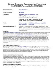
ITEM # REGULATIONS GENERAL DESCRIPTION<br />
PMR Nevada <strong>RCRA</strong> <strong>Permit</strong> <strong>Application</strong> - Completeness Checklist<br />
LOCATION IN<br />
APPLICATION<br />
Was the current version of the EPA Form 8700-23 used? Form 8700-23 (2012)<br />
G-0 270.10<br />
270.10(a)<br />
GENERAL APPLICATION REQUIREMENTS Introduction<br />
G-1<br />
270.10(c) <strong>Permit</strong> application completed and signed Part A<br />
G-2 270.10(b)<br />
Who applies - When facility is owned by one person but is<br />
operated by another, it is the operator's duty to obtain a permit.<br />
The owner must also sign the permit application Introduction<br />
G-3 270.10(c) Completeness - all elements included<br />
Information requirements - information in 270.13 and applicable<br />
G-4 270.10(d) sections of 270.14 through 270.29<br />
Existing HWM<br />
Not Applicable -<br />
facilities<br />
New Facility<br />
G-5 270.10(e)(1) Must submit Part A Not Applicable<br />
G-6 270.10(e)(2) Not Applicable<br />
G-7 270.10(e)(3) Not Applicable<br />
G-8<br />
New HWM<br />
facilities<br />
270.10(e)(4) Timely Submittal of Part B Not Applicable<br />
264.11 <strong>Application</strong> of an EPA ID number Part A<br />
G-9 270.10(f)(1) No construction before submittal of Parts A and B…<br />
Must submit Parts A and B at least 180 days before construction<br />
Not Applicable<br />
G-10 270.10(f)(2) is expected to commence Part A<br />
G-11 270.10(f)(3) Construction of an incinerator of PCBs Not Applicable<br />
Not Applicable -<br />
Updating <strong>Permit</strong><br />
Initial application<br />
<strong>Application</strong>s<br />
270.10(g)(1)<br />
submittal<br />
G-12<br />
270.72 Amendment to Part A - as necessary for compliance Not Applicable<br />
G-13 270.10(i) Re-applications - 180 before the expiration of the existing permit Not Applicable<br />
G-14 270.10(h) Recordkeeping - at least 3 years 9.0; 23.13<br />
Exposure<br />
24.0 and 27.0;<br />
Information<br />
Not Applicable<br />
G-15 270.10(j)(1) Re: surface impoundments and landfills…. Not Applicable<br />
G-16 270.10(j)(2) Not Applicable<br />
G-17 270.10(k) Not Applicable<br />
ADMIN<br />
COMPLETE<br />
(Y / N / NA)<br />
TECH<br />
COMPLETE<br />
(Y / N / NA)<br />
COMMENTS<br />
Page 1 of 18<br />
March 2013
ITEM # REGULATIONS GENERAL DESCRIPTION<br />
PMR Nevada <strong>RCRA</strong> <strong>Permit</strong> <strong>Application</strong> - Completeness Checklist<br />
LOCATION IN<br />
APPLICATION<br />
270.11<br />
SIGNATORIES TO PERMIT APPLICATIONS AND<br />
REPORTS<br />
S-1 270.11(a)(1) For a corporation Part A<br />
S-2 270.11(a)(2) For partnership or sole proprietorship Not Applicable<br />
S-3 270.11(a)(3) For government or public agency Not Applicable<br />
S-4 270.11(b) Reports signed by authorized representative Introduction<br />
S-5 270.11(b)(1) Written authorization Introduction<br />
S-6 270.11(b)(2) Authorization for a responsible position Introduction<br />
S-7 270.11(b)(3) Submittal of written authorization Introduction<br />
S-8 270.11(c) Change to authorization for signing reports Introduction<br />
S-9 270.11(d) Certification for signature Introduction<br />
270.12 CONFIDENTIALITY OF INFORMATION<br />
"confidential business information" stamped on each page<br />
Introduction<br />
I-1 270.12(12)(a) containing such information Not Applicable<br />
I-2 270.12(12)(b) Name and address of permit applicant are public information Not Applicable<br />
270.13 CONTENTS OF PART A APPLICATION<br />
270.13(a) Description of the activities which require a <strong>RCRA</strong> permit, and<br />
A-1<br />
270.13(m) description of the nature of the business Part A<br />
A-2 270.13(b) Name , mailing address, location (UTM coordinates) Part A<br />
A-3 270.13(c) NAICS codes Part A<br />
270.13(d) Operator/Owner's name, address, phone number, and ownership<br />
A-4<br />
270.13(e) status Part A<br />
No; property is<br />
A-5 270.13(f) Indian Lands?<br />
privately owned<br />
New Facility; initial<br />
A-6 270.13(g) New or Existing Facility<br />
Part A application<br />
A-7 270.13(h) Existing Facility…<br />
Description of processes for treating, storing and disposing of<br />
Not Applicable<br />
A-8 270.13(i) hazardous waste (design capacity).<br />
Identify: hazardous waste codes to be treated, stored; estimate of<br />
Part A<br />
A-9 270.13(j) annual quantity; general description of the process used Part A<br />
ADMIN<br />
COMPLETE<br />
(Y / N / NA)<br />
TECH<br />
COMPLETE<br />
(Y / N / NA)<br />
COMMENTS<br />
Page 2 of 18<br />
March 2013
PMR Nevada <strong>RCRA</strong> <strong>Permit</strong> <strong>Application</strong> - Completeness Checklist<br />
ITEM # REGULATIONS GENERAL DESCRIPTION<br />
List all permits or construction approvals associated with the<br />
facility:<br />
(a) HW Management – <strong>RCRA</strong><br />
(b) UIC under CWA<br />
(c) NPDES under CWA<br />
(d) PSD under CAA<br />
(e) Non-attainment under CAA<br />
(f) NESHAPS under CAA<br />
(g) Ocean dumping under MPRSA<br />
(h) Dredge or fill under CWA<br />
LOCATION IN<br />
APPLICATION<br />
A-10 270.13(k) (i) Other including state or county Part A<br />
Topographic Map<br />
1-mile radius<br />
facility intake and discharge location<br />
TSF<br />
UICs<br />
Wells within 1/4 mile<br />
Part A<br />
Springs within 1/4 mile<br />
Appendix 1-A and<br />
A-11 270.13(l) water body within 1/4 mile<br />
Appendix 11-A<br />
A-12 270.13(n) Identify hazardous debris at the TSF<br />
GENERAL REQUIREMENTS FOR CONTENTS OF PART<br />
2-A<br />
General<br />
270.14<br />
B APPLCIATION<br />
Information Introduction<br />
B-1 270.14(b)(1) General description of the facility 1.0<br />
B-1 264.1 Purpose, Scope, and Applicability Introduction, 1.0<br />
B-1 264.3 Relationship to interim status standards Not Applicable<br />
B-1 264.4 Imminent Hazard Action Not Applicable<br />
B-1 264.10 Applicability of Part B<br />
Manages waste generated on-site<br />
Introduction<br />
B-1 264.12(b) Manages waste generated off-site 2.0, Appendix 2-A<br />
Not Applicable;<br />
currently no<br />
hazardous waste<br />
B-1 264.12(b) Required Notices<br />
activity occurring<br />
B-1 270.14(a) Engineering drawings Appendix 1-A<br />
B-2 270.14(b)(2) Chemical and physical analysis of wastes 2.3.1, Appendix 2-E<br />
B-3 270.14(b)(3) Waste Analysis Plan Appendix 2-A<br />
B-3 264.13(b)(1) Parameters 2.3, Appendix 2-A<br />
ADMIN<br />
COMPLETE<br />
(Y / N / NA)<br />
TECH<br />
COMPLETE<br />
(Y / N / NA)<br />
COMMENTS<br />
Page 3 of 18<br />
March 2013
ITEM # REGULATIONS GENERAL DESCRIPTION<br />
PMR Nevada <strong>RCRA</strong> <strong>Permit</strong> <strong>Application</strong> - Completeness Checklist<br />
LOCATION IN<br />
APPLICATION<br />
B-3 264.13(b)(1) Rationale 2.4, Appendix 2-A<br />
B-3 264.13(b)(2) Test Methods 2.5, Appendix 2-A<br />
B-3 264.13(b)(3) Sampling Methods 2.6, Appendix 2-A<br />
B-3 264.13(b)(4)<br />
264.13(b)(5)<br />
Frequency of Analysis 2.7, Appendix 2-A<br />
B-3<br />
264.13(c)<br />
264.13(b)(6)<br />
Off-site generated waste 2.8, Appendix 2-A<br />
B-3<br />
264.17<br />
264.13(b)(6)<br />
Ignitable, Reactive, or Incompatible 2.9, Appendix 2-A<br />
B-3<br />
264.314 Bulk and Containerized Liquids in Landfill 2.10, Not Applicable<br />
B-3 264.13(b)(6) Incinerators 2.11, Not Applicable<br />
B-3 264.1100 Containment Buildings 2.12, Not Applicable<br />
B-3<br />
264.13(b)(6)<br />
264.73<br />
Part 268 LDRs 2.13, Appendix 2-A<br />
B-4 270.14(b)(4) Security Measures 3.0<br />
B-4 264.14(b) Security Procedures and Equipment 3.0<br />
B-4 264.14(b)(1) 24-hour surveillance system 3.1<br />
B-4 264.14(b)(2) Barrier to entry, control entry 3.2, 3.3<br />
B-4 264.14(c) Warning signs 3.3<br />
B-5 270.14(b)(5) A copy of the general inspection schedule<br />
Written Inspection Schedule:<br />
1. Monitoring equipment<br />
2. Safety/emergency equipment<br />
3. Security devices<br />
4.0, Appendix 4-A<br />
B-5 264.15(b)(1) 4. Operating/structural equipment Appendix 4-A<br />
B-5 264.15(b)(3) Identify types of problems (malfunctions or deterioration) 4.0, Appendix 4-A<br />
B-5 264.15(b)(4)<br />
Frequency of Inspection [Based on rate of deterioration of<br />
equipment and probability of environmental/human health<br />
incident] 4.0, Appendix 4-A<br />
B-5 264.15c) Schedule of Remedial Action Appendix 4-A<br />
B-5 264.15(d) Inspection Log 4.0, Appendix 4-B<br />
4.0, Appendix 4-A,<br />
B-5 270.15(b)(5) Specific Inspection Requirements<br />
4-B<br />
ADMIN<br />
COMPLETE<br />
(Y / N / NA)<br />
TECH<br />
COMPLETE<br />
(Y / N / NA)<br />
COMMENTS<br />
Page 4 of 18<br />
March 2013
PMR Nevada <strong>RCRA</strong> <strong>Permit</strong> <strong>Application</strong> - Completeness Checklist<br />
ITEM # REGULATIONS GENERAL DESCRIPTION<br />
LOCATION IN<br />
APPLICATION<br />
4.0, Appendix 4-A,<br />
5.7, 22.2, 22.3, 22.4,<br />
B-5 264.174 Containers: Inspect at least weekly<br />
22.8,<br />
4.0, Appendix 4-A,<br />
B-5 264.195 Tank System: Develop schedule and inspect at least once daily 23.5, 23.6, 23.7, 23.8<br />
4.0, Appendix 4-A,<br />
B-5 264.195(a) Overfill Controls: Develop and follow schedule for inspection 23.6<br />
B-5 264.195(b)(1) Aboveground portions: Check for corrosion or releases 4.0, Appendix 4-A<br />
Data from monitoring and leak detection equipment: Analyze 4.0, Appendix 4-A,<br />
B-5 264.195(b)(2) data to ensure tank is operating according to design<br />
23.8<br />
Construction Materials & Surrounding Area: Check for erosion<br />
or releases<br />
4.0, Appendix 4-A,<br />
B-5 264.195(b)(3) check for erosion<br />
23.8<br />
4.0, Appendix 4-B,<br />
B-5 264.195(b)(3) Surrounding Area<br />
23.8<br />
Cathodic Protection Systems (if present): Inspect according to Not Applicable, 1.5,<br />
B-5 264.195(c) minimum schedule<br />
23.1<br />
B-5 264.226(b) Surface Impoundments: Inspect a least weekly and after storms<br />
Overtopping Control System: Check for deterioration,<br />
Not Applicable, 24.0<br />
B-5 264.226(b)(1) malfunction, or improper operation<br />
Impoundment Contents: Check for sudden drops in level of<br />
Not Applicable<br />
B-5 264.226(b)(2) contents<br />
Containment Devices: Check for severe erosion or other signs of<br />
Not Applicable<br />
B-5 264.226(b)(3) deterioration Not Applicable<br />
B-5 Structural Integrity: Certification from qualified engineer Not Applicable<br />
264.226(d) Leak Detection System: Record amount of liquids removed at<br />
B-5<br />
270.17(c) least once each week. Not Applicable<br />
B-5 264.254 Waste Piles: Inspect at least weekly and after storms Not Applicable, 25.0<br />
B-5 264.273(g) Land Treatment: Inspect at least weekly and after storms<br />
Run-on/Run-off Control Systems: Check for deterioration,<br />
Not Applicable, 27.0<br />
B-5 264.273(g)(1) malfunctions, or improper operation Not Applicable<br />
B-5 264.303(b) Inspections for Landfills Not Applicable, 28.0<br />
Not Applicable; only<br />
batch feed to the<br />
B-5 264.347(b) Inspections for Incinerators<br />
retort, 26.0<br />
4.0, Appendix 4-A,<br />
B-5 264.602 Inspections for Miscellaneous Units - Retort<br />
Appendix 4-B, 30.1.5<br />
ADMIN<br />
COMPLETE<br />
(Y / N / NA)<br />
TECH<br />
COMPLETE<br />
(Y / N / NA)<br />
COMMENTS<br />
Page 5 of 18<br />
March 2013
PMR Nevada <strong>RCRA</strong> <strong>Permit</strong> <strong>Application</strong> - Completeness Checklist<br />
ITEM # REGULATIONS GENERAL DESCRIPTION<br />
LOCATION IN<br />
APPLICATION<br />
4.0, Appendix 4-A,<br />
B-5 264.602 Inspections for Miscellaneous Units - Filter Press<br />
Appendix 4-B, 30.2<br />
Not Applicable; no<br />
B-6 270.14(b)(6) Justification for waiver of Preparedness and Prevention<br />
waiver requested<br />
B-6 264.32 Required Equipment 5.0<br />
B-6 264.33 Testing and maintenance of equipment 5.7<br />
B-6 264.34 Access to communications or alarm system 5.5.1<br />
B-6 264.35 Required aisle space<br />
Arrangements with local authorities:<br />
5.6<br />
• Police<br />
• Fire<br />
• Emergency Response Team<br />
B-6 264.37<br />
• Local Hospitals Appendix 6-A<br />
B-6 264.37 Document Agreement Refusal 5.2.1<br />
B-6 264.5 Applicability 6.0, Appendix 6-A<br />
B-6 264.51 Purpose and implementation of contingency plan 6.0, Appendix 6-A<br />
B-7 270.14(b)(7) Copies of the Contingency Plan Appendix 6-A<br />
B-7 264.52 Content of contingency plan<br />
Arrangements with local authorities: police, fire, emergency<br />
6.0, Appendix 6-A<br />
B-7 264.52(c) response team<br />
Emergency Coordinators: name, address, home phone number,<br />
5.2.1<br />
B-7 264.52(d) office phone number Appendix 6-A<br />
B-7 264.52(e) Emergency Equipment List and Location Appendix 6-A<br />
B-7 264.52(f) Evacuation Plan 6.0<br />
B-7 264.53 Copies of contingency plan 6.0, Appendix 6-A<br />
B-7 264.54 Amendment of contingency plan 6.0, Appendix 6-A<br />
B-7 264.55 Emergency Coordinator Appendix 6-A<br />
B-7 264.56 Emergency Procedures 6.0<br />
B-7 264.7 Applicability 9.0<br />
B-7 264.71 Use of manifest system 9.0<br />
B-7 264.72 Manifest discrepancies 9.0<br />
B-3 264.73 Operating record 9.0<br />
B-8 270.14(b)(8) Safety procedures, equipment, construction to prevent: 7.0<br />
B-8 270.14(b)(8)(i) Unloading 7.0<br />
B-8 270.14(b)(8)(ii) Runoff Not Applicable<br />
ADMIN<br />
COMPLETE<br />
(Y / N / NA)<br />
TECH<br />
COMPLETE<br />
(Y / N / NA)<br />
COMMENTS<br />
Page 6 of 18<br />
March 2013
ITEM # REGULATIONS GENERAL DESCRIPTION<br />
PMR Nevada <strong>RCRA</strong> <strong>Permit</strong> <strong>Application</strong> - Completeness Checklist<br />
LOCATION IN<br />
APPLICATION<br />
B-8 270.14(b)(8)(iii) Water Supplies 7.1<br />
B-8 270.14(b)(8)(iv) Equipment and Power Failure 1.4<br />
B-8 270.14(b)(8)(v) Personal Protection Procedures 7.1<br />
B-8 270.14(b)(8)(v) Procedures to minimize release to the atmosphere<br />
Prevention of accidental ignition, reaction of ignitable, reactive,<br />
1.1.4<br />
B-9 270.14(b)(9) or incompatible wastes 7.0<br />
B-9 264.17(a) Prevent Ignition Not Applicable, 8.0<br />
B-9 264.17(b) Prevent Reaction Not Applicable, 8.0<br />
B-9 264.17(a),(b) Precautions to prevent ignition of reaction Not Applicable, 8.0<br />
B-9 264.17(a) Precautions for handling and mixing 8.1<br />
B-9 264.17(c) Documentation of Adequacy Not Applicable, 8.0<br />
General requirements for ignitable, reactive, or incompatible Not Applicable, 2.0,<br />
B-3, B-9, and T-11 264.17<br />
wastes<br />
8.0<br />
B-10 270.14(b)(10) Traffic pattern information 10.0<br />
Show turns across traffic lanes and stacking lanes, if appropriate.<br />
B-10 Estimate of number and types of vehicles around the facility 10.2<br />
B-10 Information about waste transfer or pick-up stations Not Applicable<br />
B-10 Quantity of waste moved per movement per vehicle Not Applicable, 10.2<br />
B-10 Traffic control signs and persons 10.3<br />
B-10 Road surface composition and load-bearing capacity 10.4<br />
B-10 Hauling route of waste to treatment location 10.5<br />
B-11 270.14(b)(11) Facility location information<br />
11.0, Appendix 11-A,<br />
Appendix 11-B<br />
ADMIN<br />
COMPLETE<br />
(Y / N / NA)<br />
TECH<br />
COMPLETE<br />
(Y / N / NA)<br />
Location of nearest community and potential impact on community, fire department other emergency facilities. Include locations based on GPS data.<br />
Political jurisdiction in which facility is proposed to be located<br />
B-11 270.14(b)(11)(i) [county, township, or election district]<br />
Indication of whether facility is listed in Appendix VI of 264<br />
1.0<br />
B-11 270.14(b)(11)(i) (new facilities) Yes, 11.0<br />
B-11<br />
270.14(b)(11)(ii)<br />
264.18(a)<br />
New facility must meet seismic standards and be located at<br />
least 200 feet from a fault which has had displacement in<br />
Holocene time. Yes, 11.0<br />
B-11 270.14(b)(11)(iii) Copy of Federal Insurance Association (FIA) or other flood map. Appendix 11-A, 11-B<br />
COMMENTS<br />
Page 7 of 18<br />
March 2013
PMR Nevada <strong>RCRA</strong> <strong>Permit</strong> <strong>Application</strong> - Completeness Checklist<br />
ITEM # REGULATIONS GENERAL DESCRIPTION<br />
LOCATION IN<br />
APPLICATION<br />
Not Applicable,<br />
B-11 270.14(b)(11)(iv) If facility is located in 100-year floodplain:<br />
Plans and schedule for future compliance [Applicable for<br />
Appendix 11-A<br />
B-11 270.14(b)(11)(v) existing facilities not in compliance with 40 CFR 264.18(b).] Not Applicable, 11.2<br />
B-12 270.14(b)(12) Training programs in compliance with 264.16 12.0<br />
B-12<br />
270.14(b)(12)<br />
264.16(a)(1)<br />
Outline of Introductory and Continuing Training Programs<br />
[Facility personnel must successfully complete classroom or onthe-job<br />
training which will allow them to responsibly perform in<br />
their positions.] Appendix 12-A<br />
B-12 264.16(a)(1), (2) Relevance of training to job tasks Appendix 12-A<br />
B-12 264.16(a)(2)<br />
Training Director [Program must be directed by person<br />
trained in HW procedures.] Appendix 120-A<br />
B-12 264.16(a)(3)<br />
Training for Emergency Response [At a minimum, personnel<br />
must be made familiar with emergency procedures,<br />
equipment, and systems.] 12.0, Appendix 12-A<br />
B-12 264.16(a)(b) Training within 6 months of hire. 12.0, Appendix 12-A<br />
B-12 264.16(a)(c) Annual review 12.0, Appendix 12-A<br />
B-12 264.16(d), (e) Maintenance of training records 12.0, Appendix 12-A<br />
B-11 264.3 Applicability 7.0<br />
B-11 264.31 Design and operation of the facility 1.0<br />
B-13 270.14(b)(13) A copy of the closure plan and, if applicable, post closure plan 13.0, Appendix 13-A<br />
B-13 264.111 Closure Performance Standard 13.1<br />
B-13 264.111(a) Further maintenance [Minimize need] 13.1.1<br />
B-13 264.111(b) Post-Closure Escape [Control, Minimize, Eliminate] 13.1.2<br />
B-13 264.111(c) Unit-specific closure requirements 13.1.3<br />
B-13 264.111(b) Steps for Partial and/or Final Closure at any point 13.1.4<br />
B-13 264.112(b)(1)<br />
Description of how each HWMU will be closed in accordance<br />
with 264.111<br />
Final closure of the facility, in accordance with 264.11.<br />
[Identify the max extent of the operations which will be<br />
Appendix 13-A<br />
B-13 264.112(b)(2)<br />
unclosed during the active life of the facility.] Appendix 13-A<br />
B-13 264.112(b)(3) Max inventory of HW ever on-site 13.4<br />
ADMIN<br />
COMPLETE<br />
(Y / N / NA)<br />
TECH<br />
COMPLETE<br />
(Y / N / NA)<br />
COMMENTS<br />
Page 8 of 18<br />
March 2013
PMR Nevada <strong>RCRA</strong> <strong>Permit</strong> <strong>Application</strong> - Completeness Checklist<br />
ITEM # REGULATIONS GENERAL DESCRIPTION<br />
Methods for removing, transporting, treating, storing or<br />
LOCATION IN<br />
APPLICATION<br />
B-13<br />
disposing of all HW. 13.4<br />
B-13 Types of off-site HWMU's to be used, if applicable<br />
Steps to remove or decontaminate all HW residues and<br />
13.4<br />
B-13 264.112(b)(4)<br />
contaminated units/parts<br />
Other activities necessary during closure Specific<br />
Requirements (264.178, 264.197, 264.228, 264.258, 264.280,<br />
13.4<br />
B-13 264.112(b)(5)<br />
264.310, 264.351, 264.601, 264.603) 13.4<br />
B-13 264.112(b)(6) Schedule for Closure<br />
Estimate of final closure year<br />
13.7<br />
B-13 264.112(b)(7)<br />
[if using trust fund for financial assurance] Not Applicable , 13.8<br />
B-13 264.112(b)(8) Alternative Requirements Not Applicable, 13.9<br />
B-13 264.118(a) Written [Post-Closure Plan] Not Applicable, 13.10<br />
B-13 264.118(b) Post-Closure activities and frequency Not Applicable, 13.11<br />
B-13 264.118(b)(1) Monitoring activities and frequency Not Applicable, 13.10<br />
B-13 264.118(b)(2) Maintenance activities and frequency Not Applicable, 13.10<br />
B-13 264.118(b)(2)(i) Integrity of containment systems Not Applicable, 13.10<br />
B-13 264.118(b)(2)(ii) Function of monitoring equipment Not Applicable, 13.10<br />
B-13 264.118(b)(3) Contact info during post-closure care Not Applicable, 13.10<br />
B-13 264.118(b)(3) Alternative Requirements Not Applicable, 13.10<br />
B-14 270.14(b)(14) Documentation filed (required under 264.119) for closed units<br />
This applies to Closed HW Disposal Units<br />
Not Applicable, 14.0<br />
264.119 Notice Documentation Not Applicable, 14.0<br />
B-14 270.14(b)(15) Post-Closure Notices<br />
Closure estimates (required under 264.142) and financial<br />
Not Applicable, 14.0<br />
B-15 270.14(b)(15) assurance (required under 264.143) 15.0<br />
B-15 246.142 Third Party Cost Estimate Appendix 15-A<br />
ADMIN<br />
COMPLETE<br />
(Y / N / NA)<br />
TECH<br />
COMPLETE<br />
(Y / N / NA)<br />
COMMENTS<br />
Page 9 of 18<br />
March 2013
ITEM # REGULATIONS GENERAL DESCRIPTION<br />
B-15 264.143<br />
B-16 270.14(b)(16)<br />
PMR Nevada <strong>RCRA</strong> <strong>Permit</strong> <strong>Application</strong> - Completeness Checklist<br />
Financial Assurance for Closure<br />
Closure trust fund [264.143(a)]<br />
Surety bond into trust fund [264.143(b)]<br />
Surety bond guaranteeing performance of closure [264.143c]<br />
Closure letter of credit [264.143(d)]<br />
Closure insurance [264.13(e)<br />
Financial test and corporate guarantee for closure [264.143(f)]<br />
Multiple financial mechanisms [264.143(g)]<br />
Financial mechanism for multiple facilities [264.143(h)]<br />
Release of owner/operator from these requirements<br />
[264.143(i)] 15.3<br />
LOCATION IN<br />
APPLICATION<br />
The most recent post-closure estimates (required under<br />
264.144) and financial assurance (required under 264.145),<br />
where applicable. Not Applicable, 14.0<br />
B-16 264.142 Third party cost estimate Not Applicable, 16.0<br />
B-16 264.143 Financial assurance for closure Not Applicable, 14.0<br />
Closure trust fund [264.143(a)]<br />
Surety bond into trust fund [264.143(b)]>Surety bond<br />
guaranteeing performance of closure [264.143c]<br />
Closure letter of credit [264.143(d)]>Closure insurance<br />
[264.13(e)<br />
Financial test and corporate guarantee for closure [264.143(f)]<br />
Multiple financial mechanisms [264.143(g)]<br />
Financial mechanism for multiple facilities [264.143(h)]<br />
Release of owner/operator from these requirements<br />
[264.143(i)]<br />
B-16<br />
B-17 270.14(b)(17)<br />
Insurance policy or other documentation in compliance with<br />
264.147, where applicable. 17.0<br />
B-17 264.147(a) Coverage for Sudden Accidental Occurrences<br />
Liability insurance [264.147(a)(1)]<br />
Financial test of guarantee of liability coverage<br />
[264.147(a)(2)]<br />
Letter of credit [264.147(a)(3)]<br />
Surety bond [264.147(a)(4)]<br />
Trust fund [264.147(a)(5)<br />
17.2<br />
B-17<br />
Multiple liability mechanisms [264.147(a)(6) 17.2<br />
Not Applicable, 14.0,<br />
16.0<br />
ADMIN<br />
COMPLETE<br />
(Y / N / NA)<br />
TECH<br />
COMPLETE<br />
(Y / N / NA)<br />
COMMENTS<br />
Page 10 of 18<br />
March 2013
ITEM # REGULATIONS GENERAL DESCRIPTION<br />
PMR Nevada <strong>RCRA</strong> <strong>Permit</strong> <strong>Application</strong> - Completeness Checklist<br />
B-17 264.147(b) Coverage for Non-Sudden Accidental Occurrences<br />
Liability insurance [264.147(a)(1)]<br />
Financial test of guarantee of liability coverage<br />
[264.147(a)(2)]<br />
Letter of credit [264.147(a)(3)]<br />
Surety bond [264.147(a)(4)]<br />
Trust fund [264.147(a)(5)<br />
B-17<br />
Multiple liability mechanisms [264.147(a)(6) 17.3<br />
LOCATION IN<br />
APPLICATION<br />
B-17 264.147(c) Request for Variance Not Applicable<br />
B-18 270.14(b)(18)<br />
B-19 270.14(b)(19)<br />
Coverage by a State financial mechanism in compliance with<br />
264.149 and 264.150, where appropriate Not Applicable<br />
A 1" = 200 ft topographic map with contours showing 1000 ft<br />
around the facility and:<br />
(i) Map scale and date<br />
(ii) 100-year floodplain<br />
(iii) Surface waters<br />
(iv) Surrounding land uses<br />
(v) Wind rose<br />
(vi) Orientation of the map<br />
(vii) Legal boundaries of the facility<br />
(viii) Access control<br />
(ix) Injection and withdrawal wells both on and offsite<br />
(x) Buildings, structures<br />
(xi) Barriers for drainage or flood control<br />
(xii) Location of operational units<br />
Part A, Introduction,<br />
18.0, Appendices 1-<br />
A, 11-A, and 11-B<br />
ADMIN<br />
COMPLETE<br />
(Y / N / NA)<br />
TECH<br />
COMPLETE<br />
(Y / N / NA)<br />
COMMENTS<br />
Must show a distance of 1,000 ft around the unit at a scale of 1" to not more than 200' (multiple maps may be submitted at this scale); should be shown and should be similar to Part A topographic map.<br />
Use GPS coordinates for locations of the below requirements for the map.<br />
B-19<br />
Contours [The contour interval must be sufficient to clearly<br />
show the pattern of surface water flow in the vicinity of and<br />
from each operational unit of the facility. For example,<br />
contours with an interval of 5', if relief is greater than 20', or<br />
an interval of 2' if relief is less than 20'. Mountainous areas<br />
should use large contour intervals to adequately show<br />
topographic profiles of facilities.]<br />
B-19 270.14(b)(19)(i) Map scale and date [Other scales may be used if justified.]<br />
Part A, Introduction,<br />
18.0, Appendices 1-<br />
A, 11-A, and 11-B<br />
Part A, Introduction,<br />
18.0, Appendices 1-<br />
A, 11-A, and 11-B<br />
Page 11 of 18<br />
March 2013
ITEM # REGULATIONS GENERAL DESCRIPTION<br />
B-19<br />
270.14(b)(19)(ii)<br />
NAC 444.8456[1.c] The 100-year floodplain area<br />
PMR Nevada <strong>RCRA</strong> <strong>Permit</strong> <strong>Application</strong> - Completeness Checklist<br />
B-19 270.14(b)(19)(iii) Surface waters (including intermittent streams)<br />
Surrounding land use (residential, commercial, agricultural,<br />
recreational) [Include considerations of EJ issues or National<br />
B-19 270.14(b)(19)(iv) Historic Preservation Act (especially Indian lands]<br />
B-19 270.14(b)(19)(v)<br />
LOCATION IN<br />
APPLICATION<br />
Part A, Appendices<br />
11-A and 11-B<br />
18.0, Appendices 1-<br />
A, Appendix 11-A,<br />
and 11-B<br />
Appendices 11-A and<br />
11-B<br />
Wind Rose (i.e., prevailing wind-speed and direction) [The<br />
frequency of occurrence of various wind directions should be<br />
compared to sensitive (local/regional) receptor points<br />
downwind.] Appendix 11-B<br />
B-19 270.14(b)(19)(vi) Map orientation Maps and Figures<br />
B-19 270.14(b)(19)(vii) Legal boundaries Appendix 11-C<br />
B-19 270.14(b)(19)(viii) Access Control (fences, gate) 3.2, Appendix 1-A<br />
Not Applicable,<br />
Appendices 1-A and<br />
B-19 270.14(b)(19)(ix) Injection and withdrawal wells (on-site and off-site)<br />
Buildings and other structures [See 40 CFR 270.14(b)(19)(x) for<br />
11-B, 18.0<br />
B-19 270.14(b)(19)(x) an example list.] 18. 0, Appendix 1-A<br />
3.2, 18.0, Appendix<br />
B-19 270.14(b)(19)(xi) Drainage and flood control barriers<br />
1-A<br />
1.0, 18.0, Appendix<br />
B-19 270.14(b)(19)(xii)<br />
Location of Operational TSD Units(s) and Decontamination<br />
Areas:<br />
1-A<br />
• Property boundary and distance of treatment unit to<br />
property boundaries<br />
1-A, Appendix 1-A<br />
• Distance to buildings on/off-site<br />
• Distance to public roadways<br />
• Distance to closest receptor [270.33(e)]<br />
• [Receptors include human and environmental<br />
B-19<br />
receptors within the facility boundary.]<br />
ADMIN<br />
COMPLETE<br />
(Y / N / NA)<br />
TECH<br />
COMPLETE<br />
(Y / N / NA)<br />
COMMENTS<br />
Page 12 of 18<br />
March 2013
ITEM # REGULATIONS GENERAL DESCRIPTION<br />
PMR Nevada <strong>RCRA</strong> <strong>Permit</strong> <strong>Application</strong> - Completeness Checklist<br />
B-19 270.14(c) • Additional info on the topographic map:<br />
• Uppermost aquifer and hydraulically connected<br />
aquifers beneath facility property [270.14(c)(2)]<br />
• Groundwater flow direction [270.14(c)(2)]<br />
• Waste management areas[270.14(c)(3<br />
• Point of compliance location [270.14(c) (3)<br />
• [Defined in 264.95; however, for OB/OD units, this<br />
will be determined on a case-by-case basis and may<br />
be at the BOUNDARY DETERMINATION.]<br />
• Location of groundwater monitoring wells<br />
[270.14(c)(3)]<br />
• Extent of any groundwater contaminant<br />
plume[[270.14(c)(4)(i)]<br />
• Location of unsaturated zone monitoring [270.23(e)]<br />
[If unit incorporates the soil as part of the zone of<br />
engineering control, the monitoring of this zone<br />
B-19<br />
should be shown]<br />
B-20 270.14(b)(21)<br />
Notice of approval of petition for extension for land disposal<br />
facilities, if applicable.<br />
[If case-by-case extension has been approved under 268.5 or a petition has been approved under 268.6]<br />
LOCATION IN<br />
APPLICATION<br />
20.0, Appendix 20-A<br />
through 20-C<br />
Not Applicable, no<br />
extension requested<br />
B-20 270.14(b)(21) Copy of Notice of Approval Not Applicable<br />
B-20 270.14(b)(22)<br />
Additional information<br />
B-21 270.14(c)(1)<br />
B-22 270.14(c)(2)<br />
B-23 270.14(c)(3)<br />
Summary of Pre-<strong>Application</strong> Meeting:<br />
• List of Attendees<br />
• Attendees Addresses<br />
• Copies of Written Comments<br />
• Copies of Materials Submitted<br />
A summary of groundwater monitor data under 265.90-94),<br />
where applicable<br />
Identification of:<br />
• The uppermost aquifer,<br />
• Hydraulically connected aquifers,<br />
• Flow direction and rate, and<br />
• Basis for such identification<br />
On the topo map, a delineation of the waste management area,<br />
property boundary, the proposed point of compliance (264.95),<br />
proposed GW monitoring wells (264.97), and info from<br />
270.14(c)(2)<br />
Intro, Appendices I-A<br />
and I-B<br />
20.0,<br />
Appendices 20-A<br />
through 20-C<br />
20.0,<br />
Appendices 20-A<br />
through 20-C<br />
18.0, 20.0,<br />
Appendices 1-A,<br />
11-B, and 20-A<br />
through 20-C<br />
ADMIN<br />
COMPLETE<br />
(Y / N / NA)<br />
TECH<br />
COMPLETE<br />
(Y / N / NA)<br />
COMMENTS<br />
Page 13 of 18<br />
March 2013
ITEM # REGULATIONS GENERAL DESCRIPTION<br />
B-24 270.14(c)(4)<br />
B-25 270.14(c)(5)<br />
B-26 270.14(c)(6)<br />
B-27 270.14(c)(7)<br />
B-28 270.14(c)(8)<br />
PMR Nevada <strong>RCRA</strong> <strong>Permit</strong> <strong>Application</strong> - Completeness Checklist<br />
Description of any plume of contamination from a regulated<br />
unit:<br />
(i) The extent of the plume on the topo map<br />
(ii) Identification of concentrations of constituents in Appendix<br />
IX of 264<br />
A detailed GW monitoring program with engineering report<br />
LOCATION IN<br />
APPLICATION<br />
Not Applicable, 20.0,<br />
Appendix 20-B, 20-C<br />
(264.97) Not Applicable, 20.0<br />
If a hazardous constituent has not been detected at time of<br />
application, establish a detection monitoring program<br />
(264.98):<br />
(i) Indicator parameters, waste constituents, or reaction products<br />
(ii) A proposed groundwater monitoring system<br />
(iii) Background values<br />
(iv) Proposed sampling, analysis, and statistical procedures Not Applicable, 20.0<br />
If a hazardous constituent has been detected at time of<br />
application, establish a compliance monitoring program<br />
(264.99):<br />
(i) A description of wastes previously handled<br />
(ii) A characterization of the contaminated GW<br />
(iii) A list of hazardous constituents (264.97 & 264.99) (iv)<br />
Proposed concentration limits (264.94(a)) or justification for<br />
alternate limits<br />
(v) A proposed GW monitoring system<br />
(vi) Proposed sampling, analysis, and statistical procedures<br />
(vii) A proposed Engineering Feasibility Plan for corrective<br />
action Not Applicable, 20.0<br />
If hazardous constituents have exceeded concentration limits<br />
(Table 1, 264.94) or background values, establish a corrective<br />
action program (264.100):<br />
(i) A Characterization of contaminated GW<br />
(ii) Concentration limits (264.94)<br />
(iii) A detailed corrective action program and engineering report<br />
(iv) Demonstration of adequacy of the corrective program Not Applicable, 20.0<br />
B-29 270.14(d)(1) Information on SWMUs Not Applicable, 21.0<br />
B-30 270.14(d)(2) Releases from SWMUs Not Applicable, 21.0<br />
B-31 270.14(d)(3) Results of Sampling and Analysis Not Applicable, 21.0<br />
Specific Part B Information Requirements for Containers – 270.15<br />
Description of the containment system in compliance with<br />
22.0<br />
C-1 270.15(a) 264.175 1.1, 1.2, 22.6<br />
ADMIN<br />
COMPLETE<br />
(Y / N / NA)<br />
TECH<br />
COMPLETE<br />
(Y / N / NA)<br />
COMMENTS<br />
Page 14 of 18<br />
March 2013
PMR Nevada <strong>RCRA</strong> <strong>Permit</strong> <strong>Application</strong> - Completeness Checklist<br />
ITEM # REGULATIONS GENERAL DESCRIPTION<br />
Basic design parameters, dimensions, and materials of<br />
LOCATION IN<br />
APPLICATION<br />
C-2 270.15(a)(1) construction 1.1, 1.2, 22.0<br />
Showing of how design promotes drainage or keeps containers 1.1, 1.2, Appendix 1-<br />
C-3 270.15(a)(2) from contacting standing liquid.<br />
A, 22.7<br />
1.1, Appendix 1-A,<br />
20.0, 23.6.1,<br />
Capacity of the containment system relative to the number and Table 1.2-1,<br />
C-4 270.15(a)(3) volume of containers stored<br />
Appendix 22-B<br />
Not Applicable, 1.2,<br />
Appendix 1-A, 22.6,<br />
C-5 270.15(a)(4) Provisions for preventing or managing run-on<br />
22.9<br />
Showing of how accumulated liquids can be analyzed and 1.1, 1.2, Appendix 1-<br />
C-6 270.15(a)(5) removed to prevent overflow<br />
For storage areas with containers that do not contain free liquid,<br />
A, 22.8<br />
C-7 270.15(b) a showing of compliance with 264.175(c)<br />
Test procedures and results or documentation to show wastes do<br />
22.10<br />
C-8 270.15(b)(1) not contain free liquids<br />
Description of storage area design and operation to<br />
drain/remove liquid or keep containers from contacting<br />
22.10.2<br />
C-9 270.15(b)(2) standing liquids<br />
Sketches, drawings, or data to show compliance with 264.176<br />
(ignitable reactive wastes) and 264.177(c) (incompatible wastes)<br />
22.8.2<br />
• Location of containers and buffer zone<br />
Not Applicable,<br />
C-10 270.15(15)(c)<br />
• Location of incompatible wastes<br />
22.11.1, 22.11.2<br />
Procedures in compliance with 264.177(a) & (b) and 264.17(b)<br />
& (c) for storing of incompatible wastes<br />
• Incompatible waste must not be placed in the same<br />
container [264.177(a)]<br />
• No unwashed containers [264.177(b)]<br />
• Prevent reactions [264.17(b)]<br />
• Documentation of compliance with 264.17(b)<br />
Not Applicable,<br />
C-11 270.15(d)<br />
[264.17(c)]<br />
22.11.2<br />
C-12 270.15(3) Air emission control equipment 22.12<br />
Specific Part B Information Requirements for Tanks – 270.16<br />
T-1 270.16(a)<br />
A written assessment by an independent P.E. to certify the<br />
structural integrity and suitability for handling of hazardous<br />
wastes of each tank system as required under 264.191 & 192 23.0<br />
T-2 270.16(b) Dimensions and capacity of each tank<br />
23.1, Appendices 1-<br />
A, 1-B, and<br />
Table 23.1-1<br />
ADMIN<br />
COMPLETE<br />
(Y / N / NA)<br />
TECH<br />
COMPLETE<br />
(Y / N / NA)<br />
COMMENTS<br />
Page 15 of 18<br />
March 2013
ITEM # REGULATIONS GENERAL DESCRIPTION<br />
T-3 270.16(c)<br />
T-4 270.16(d)<br />
T-5 270.16(e)<br />
T-6 270.16(f)<br />
T-7 270.16(g)<br />
270.16(g)<br />
270.16(h)(1)<br />
264.193(g)(1)<br />
T-8<br />
264.193(h)<br />
PMR Nevada <strong>RCRA</strong> <strong>Permit</strong> <strong>Application</strong> - Completeness Checklist<br />
Description of:<br />
• Feed systems,<br />
• Safety cutoff,<br />
• Bypass systems, and<br />
LOCATION IN<br />
APPLICATION<br />
• Pressure controls 23.6.1, Appendix 1-B<br />
For each tank system, a diagram of:<br />
• Piping,<br />
• Instrumentation, and<br />
• Process flow Appendix 1-B<br />
A description of materials/equipment used for external corrosion<br />
protection, as required under 264.192(a)(3)(ii) 23.1,<br />
For new tank systems, a description of how the tank system(s)<br />
will be installed in compliance with 264.192(b), (c), (d), (e);<br />
including testing plans and procedures 23.4<br />
Detailed plans and description of the secondary containment<br />
system in compliance with 264.193(a), (b), (c), (d), (e), (f):<br />
• Tank age determination [264.193(a)<br />
• Design, construction, and operation of secondary<br />
containment system [2643.193(b)-(f)]<br />
o Secondary containment and leak detection<br />
[264.193(b), (c); 264.1101(b)(3)(iii)<br />
o External liner, vault, double-walled tank or<br />
equivalent device [264.193(d), (e)]<br />
o Ancillary equipment [264.193(f)] 23.2<br />
Detailed plans, and engineering and hydrogeologic reports<br />
showing alternative safeguards<br />
Equivalent protection<br />
T-9 270.16(h)(2) A detailed assessment of hazards in event of release<br />
T-10 270.16(i)<br />
270.16(h)(2)<br />
264.193(g)(2)<br />
264.193(h) Demonstration of no substantial present/potential hazard<br />
Not Applicable, 23.4,<br />
23.5<br />
23.1, 23.5, 23.8,<br />
Appendix 6-A<br />
5.7, 8.1,<br />
Appendix 6-A<br />
264.190(a) No free liquids and location inside a building 22.4, 22.10.2<br />
264.194(b)<br />
Description of spill and overflow prevention as required under<br />
264.194(b) 23.0<br />
Detailed description of controls/practices to prevent<br />
spills/overflows 23.0<br />
ADMIN<br />
COMPLETE<br />
(Y / N / NA)<br />
TECH<br />
COMPLETE<br />
(Y / N / NA)<br />
COMMENTS<br />
Page 16 of 18<br />
March 2013
ITEM # REGULATIONS GENERAL DESCRIPTION<br />
T-11 270.16(j)<br />
PMR Nevada <strong>RCRA</strong> <strong>Permit</strong> <strong>Application</strong> - Completeness Checklist<br />
LOCATION IN<br />
APPLICATION<br />
Description of operating procedures, tank system design, facility<br />
design for ignitable/reactive and incompatible wastes as required<br />
under 264.198, 199 Not Applicable, 23.0<br />
T-11 264.198 Special requirements for ignitable or reactive wastes Not applicable, 23.10<br />
T-11 264.17(b) Special requirements for incompatible wastes Not applicable, 23.11<br />
SI-1 through<br />
SI-20 270.17<br />
Specific part B information requirements for surface<br />
impoundments<br />
W-1 though W-18 270.18 Specific part B information requirements for waste piles<br />
IN-1 through IN-16 270.19 Specific part B information requirements for incinerators<br />
LT-1 through<br />
LT-31 270.20<br />
Specific part B information requirements for land treatment<br />
facilities<br />
LF-1 through LF-19 270.21 Specific part B information requirements for landfills<br />
BF-1 through BF-<br />
16 270.22<br />
M-1 270.23<br />
M-2 270.23(a)(1)<br />
Specific part B information requirements for boilers and<br />
industrial furnaces burning hazardous waste<br />
Specific part B information requirements for miscellaneous<br />
units: Retort, Filter Press 30.0<br />
Description<br />
Retort<br />
Filter Press<br />
M-3 270.23(a)(2) Engineering drawings<br />
M-3<br />
M-3<br />
270.23(a)(2)<br />
264.601<br />
264.602<br />
Operation<br />
Retort<br />
Filter Press<br />
24.0, Not Applicable;<br />
no surface<br />
impoundments<br />
25.0, Not Applicable;<br />
no waste piles<br />
26.0, Not Applicable;<br />
no incinerators<br />
27.0, Not Applicable;<br />
no land treatment<br />
28.0, Not Applicable;<br />
no landfill<br />
29.0, Not Applicable;<br />
no boilers or<br />
industrial furnaces<br />
1.2, 30.1<br />
1.2, 30.2<br />
Appendix, 1-A,<br />
Appendix 30-A<br />
30.1<br />
30.2<br />
270.23(a)(2)<br />
264.601<br />
264.602 Maintenance 30.0<br />
ADMIN<br />
COMPLETE<br />
(Y / N / NA)<br />
TECH<br />
COMPLETE<br />
(Y / N / NA)<br />
COMMENTS<br />
Page 17 of 18<br />
March 2013
M-3<br />
M-3<br />
ITEM # REGULATIONS GENERAL DESCRIPTION<br />
PMR Nevada <strong>RCRA</strong> <strong>Permit</strong> <strong>Application</strong> - Completeness Checklist<br />
270.23(a)(2)<br />
264.601<br />
264.602 Monitoring 30.0<br />
270.23(a)(2)<br />
264.601<br />
264.602 Inspection 30.0<br />
LOCATION IN<br />
APPLICATION<br />
M-3<br />
270.23(a)(2)<br />
264.601<br />
264.602 Closure 30.0<br />
M-4 270.23(a) Post-closure requirements Not Applicable<br />
M-4 264.603 Post-closure requirements Not Applicable<br />
Not Applicable; no<br />
M-5 270.23(b) Assessments for land-based Units<br />
land-based units<br />
M-5<br />
Not Applicable; no<br />
264.601 Assessments for land-based Units<br />
land-based units<br />
Not Applicable; no<br />
M-6 270.23(c) Exposure<br />
land-based units<br />
Report on effectiveness of treatment<br />
Retort<br />
30.1<br />
M-7 270.23(d) Filter Press<br />
30.2<br />
M-8 270.23(e) Additional information none requested<br />
V-1 through V-12 270.24 Specific part B information requirements for process vents<br />
E-1 through E-15 270.25 Specific part B information requirements for equipment<br />
D-1 through D-19 270.26 Special part B information requirements for drip pads<br />
31.0, Not Applicable;<br />
no organic carbons<br />
present<br />
32.0, Not Applicable;<br />
no organic carbons<br />
present<br />
33.0, Not Applicable;<br />
no drip pads<br />
ADMIN<br />
COMPLETE<br />
(Y / N / NA)<br />
TECH<br />
COMPLETE<br />
(Y / N / NA)<br />
COMMENTS<br />
Page 18 of 18<br />
March 2013
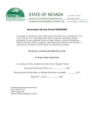
Part A <strong>Application</strong><br />
<strong>Dry</strong> <strong>Hills</strong> Treatment and Storage Facility
OMB# 2050-0024; Expires ____________<br />
SEND<br />
COMPLETED<br />
FORM TO:<br />
The Appropriate<br />
State or Regional<br />
Office.<br />
1. Reason for<br />
Submittal<br />
MARK ALL<br />
BOX(ES) THAT<br />
APPLY<br />
2. Site EPA ID<br />
Number<br />
3. Site Name Name: -<br />
4. Site Location<br />
Information<br />
Reason for Submittal:<br />
United States Environmental Protection Agency<br />
<strong>RCRA</strong> SUBTITLE C SITE IDENTIFICATION FORM<br />
To provide an Initial Notification (first time submitting site identification information / to obtain an EPA ID number<br />
for this location)<br />
To provide a Subsequent Notification (to update site identification information for this location)<br />
As a component of a First <strong>RCRA</strong> Hazardous Waste Part A <strong>Permit</strong> <strong>Application</strong><br />
As a component of a Revised <strong>RCRA</strong> Hazardous Waste Part A <strong>Permit</strong> <strong>Application</strong> (Amendment # )<br />
As a component of the Hazardous Waste Report (If marked, see sub-bullet below)<br />
EPA ID Number<br />
Site was a TSD facility and/or generator of >1,000 kg of hazardous waste, >1 kg of acute hazardous waste, or<br />
>100 kg of acute hazardous waste spill cleanup in one or more months of the report year (or State equivalent<br />
LQG regulations)<br />
DRAFT<br />
City, Town, or Village: County:<br />
Street Address:<br />
State: Country: Zip Code:<br />
5. Site Land Type Private County District Federal Tribal Municipal State Other<br />
6. NAICS Code(s)<br />
for the Site<br />
(at least 5-digit<br />
codes)<br />
7. Site Mailing<br />
Address<br />
8. Site Contact<br />
Person<br />
9. Legal Owner<br />
and Operator<br />
of the Site<br />
A. -<br />
B. -<br />
Street or P.O. Box:<br />
City, Town, or Village:<br />
State: Country: Zip Code:<br />
First Name: MI: Last:<br />
Title:<br />
Street or P.O. Box:<br />
City, Town or Village:<br />
State: Country: Zip Code:<br />
Email:<br />
Phone: Ext.: Fax:<br />
A. Name of Site’s Legal Owner:<br />
Date Became<br />
Owner:<br />
Owner Type: Private County District Federal Tribal Municipal State Other<br />
Street or P.O. Box:<br />
City, Town, or Village: Phone:<br />
State: Country: Zip Code:<br />
B. Name of Site’s Operator:<br />
Date Became<br />
Operator:<br />
Operator<br />
Type: Private County District Federal Tribal Municipal State Other<br />
EPA Form 8700-12, 8700-13 A/B, 8700-23 (Revised Page 1 of<br />
C. -<br />
D. -
EPA ID Number<br />
OMB#: 2050-0024; Expires ____________<br />
10. Type of Regulated Waste Activity (at your site)<br />
Mark “Yes” or “No” for all current activities (as of the date submitting the form); complete any additional boxes as instructed.<br />
A. Hazardous Waste Activities; Complete all parts 1-10.<br />
Y N 1. Generator of Hazardous Waste<br />
If “Yes”, mark only one of the following – a, b, or c.<br />
a. LQG: Generates, in any calendar month, 1,000 kg/mo<br />
(2,200 lbs./mo.) or more of hazardous waste; or<br />
Generates, in any calendar month, or<br />
accumulates at any time, more than 1 kg/mo (2.2<br />
lbs./mo) of acute hazardous waste; or<br />
Generates, in any calendar month, or<br />
accumulates at any time, more than 100 kg/mo<br />
(220 lbs./mo) of acute hazardous spill cleanup<br />
material.<br />
b. SQG: 100 to 1,000 kg/mo (220 – 2,200 lbs./mo) of nonacute<br />
hazardous waste.<br />
c. CESQG: Less than 100 kg/mo (220 lbs./mo) of non-acute<br />
hazardous waste.<br />
If “Yes” above, indicate other generator activities in 2-4.<br />
Y N 5. Transporter of Hazardous Waste<br />
If “Yes”, mark all that apply.<br />
a. Transporter<br />
b. Transfer Facility (at your site)<br />
Y N 6. Treater, Storer, or Disposer of<br />
Hazardous Waste Note: A hazardous<br />
waste Part B permit is required for these<br />
activities.<br />
Y N<br />
7. Recycler of Hazardous Waste<br />
Y N 8. Exempt Boiler and/or Industrial Furnace<br />
DRAFT<br />
Y N 2. Short-Term Generator (generate from a short-term or one-time<br />
event and not from on-going processes). If “Yes”, provide an<br />
explanation in the Comments section.<br />
If “Yes”, mark all that apply.<br />
a. Small Quantity On-site Burner<br />
Exemption<br />
b. Smelting, Melting, and Refining<br />
Furnace Exemption<br />
Y N 3. United States Importer of Hazardous Waste Y N 9. Underground Injection Control<br />
Y N 4. Mixed Waste (hazardous and radioactive) Generator<br />
Y N<br />
10. Receives Hazardous Waste from Off-<br />
site<br />
B. Universal Waste Activities; Complete all parts 1-2. C. Used Oil Activities; Complete all parts 1-4.<br />
Y N 1. Large Quantity Handler of Universal Waste (you<br />
accumulate 5,000 kg or more) [refer to your State<br />
regulations to determine what is regulated]. Indicate<br />
types of universal waste managed at your site. If “Yes”,<br />
mark all that apply.<br />
a. Batteries<br />
b. Pesticides<br />
c. Mercury containing equipment<br />
d. Lamps<br />
e. Other (specify)<br />
f. Other (specify)<br />
g. Other (specify)<br />
Y N 2. Destination Facility for Universal Waste<br />
Note: A hazardous waste permit may be required for this<br />
activity.<br />
Y N 1. Used Oil Transporter<br />
If “Yes”, mark all that apply.<br />
a. Transporter<br />
b. Transfer Facility (at your site)<br />
Y N 2. Used Oil Processor and/or Re-refiner<br />
If “Yes”, mark all that apply.<br />
a. Processor<br />
b. Re-refiner<br />
Y N 3. Off-Specification Used Oil Burner<br />
Y N 4. Used Oil Fuel Marketer<br />
If “Yes”, mark all that apply.<br />
a. Marketer Who Directs Shipment of Off-<br />
Specification Used Oil to Off-<br />
Specification Used Oil Burner<br />
b. Marketer Who First Claims the Used<br />
Oil Meets the Specifications<br />
EPA Form 8700-12, 8700-13 A/B, 8700-23 (Revised Page 2 of
EPA ID Number<br />
OMB#: 2050-0024; Expires ____________<br />
D. Eligible Academic Entities with Laboratories—Notification for opting into or withdrawing from managing laboratory hazardous<br />
wastes pursuant to 40 CFR Part 262 Subpart K<br />
You can ONLY Opt into Subpart K if:<br />
you are at least one of the following: a college or university; a teaching hospital that is owned by or has a formal affiliation<br />
agreement with a college or university; or a non-profit research institute that is owned by or has a formal affiliation agreement with<br />
a college or university; AND<br />
you have checked with your State to determine if 40 CFR Part 262 Subpart K is effective in your state<br />
Y N N 1. Opting into or currently operating under 40 CFR Part 262 Subpart K for the management of hazardous wastes in laboratories<br />
See the item-by-item instructions for definitions of types of eligible academic entities. Mark all that apply:<br />
Y N N<br />
a. College or University<br />
b. Teaching Hospital that is owned by or has a formal written affiliation agreement with a college or university<br />
c. Non-profit Institute that is owned by or has a formal written affiliation agreement with a college or university<br />
DRAFT<br />
2. Withdrawing from 40 CFR Part 262 Subpart K for the management of hazardous wastes in laboratories<br />
11. Description of Hazardous Waste<br />
A. Waste Codes for Federally Regulated Hazardous Wastes. Please list the waste codes of the Federal hazardous wastes handled at<br />
your site. List them in the order they are presented in the regulations (e.g., D001, D003, F007, U112). Use an additional page if more<br />
spaces are needed.<br />
B. Waste Codes for State-Regulated (i.e., non-Federal) Hazardous Wastes. Please list the waste codes of the State-Regulated<br />
hazardous wastes handled at your site. List them in the order they are presented in the regulations. Use an additional page if more<br />
spaces are needed.<br />
EPA Form 8700-12, 8700-13 A/B, 8700-23 (Revised Page 3 of
EPA ID Number<br />
12. Notification of Hazardous Secondary Material (HSM) Activity<br />
DRAFT<br />
OMB#: 2050-0024; Expires ____________<br />
Y N Are you notifying under 40 CFR 260.42 that you will begin managing, are managing, or will stop managing hazardous<br />
secondary material under 40 CFR 261.2(a)(2)(ii), 40 CFR 261.4(a)(23), (24), or (25)?<br />
13. Comments<br />
If “Yes”, you must fill out the Addendum to the Site Identification Form: Notification for Managing Hazardous Secondary<br />
Material.<br />
14. Certification. I certify under penalty of law that this document and all attachments were prepared under my direction or supervision in<br />
accordance with a system designed to assure that qualified personnel properly gather and evaluate the information submitted. Based<br />
on my inquiry of the person or persons who manage the system, or those persons directly responsible for gathering the information, the<br />
information submitted is, to the best of my knowledge and belief, true, accurate, and complete. I am aware that there are significant<br />
penalties for submitting false information, including the possibility of fines and imprisonment for knowing violations. For the <strong>RCRA</strong><br />
Hazardous Waste Part A <strong>Permit</strong> <strong>Application</strong>, all owner(s) and operator(s) must sign (see 40 CFR 270.10(b) and 270.11).<br />
Signature of legal owner, operator, or an<br />
authorized representative<br />
Name and Official Title (type or print) Date Signed<br />
(mm/dd/yyyy)<br />
EPA Form 8700-12, 8700-13 A/B, 8700-23 (Revised Page 4 of
EPA ID Number<br />
ADDENDUM TO THE SITE IDENTIFICATION FORM:<br />
NOTIFICATION OF HAZARDOUS SECONDARY MATERIAL ACTIVITY<br />
ONLY fill out this form if:<br />
1. Indicate reason for notification. Include dates where requested.<br />
DRAFT<br />
OMB#: 2050-0024; Expires ____________<br />
You are located in a State that allows you to manage excluded hazardous secondary material (HSM) under 40 CFR 261.2(a)(2)(ii),<br />
261.4(a)(23), (24), or (25) (or state equivalent). See http://www.epa.gov/epawaste/hazard/dsw/statespf.htm for a list of eligible<br />
states; AND<br />
You are or will be managing excluded HSM in compliance with 40 CFR 261.2(a)(2)(ii), 261.4(a)(23), (24), or (25) (or state<br />
equivalent) or you have stopped managing excluded HSM in compliance with the exclusion(s) and do not expect to manage any<br />
amount of excluded HSM under the exclusion(s) for at least one year. Do not include any information regarding your hazardous<br />
waste activities in this section.<br />
Facility will begin managing excluded HSM as of _____________ (mm/dd/yyyy).<br />
Facility is still managing excluded HSM/re-notifying as required by March 1 of each even-numbered year.<br />
Facility has stopped managing excluded HSM as of ____________ (mm/dd/yyyy) and is notifying as required.<br />
2. Description of excluded HSM activity. Please list the appropriate codes and quantities in short tons to describe your excluded HSM<br />
activity ONLY (do not include any information regarding your hazardous wastes). Use additional pages if more space is needed.<br />
a. Facility code<br />
(answer using<br />
codes listed in the<br />
Code List section of<br />
the instructions)<br />
b. Waste code(s) for HSM c. Estimated short<br />
tons of excluded HSM<br />
to be managed<br />
annually<br />
d. Actual short tons<br />
of excluded HSM<br />
that was managed<br />
during the most<br />
recent oddnumbered<br />
year<br />
3. Facility has financial assurance pursuant to 40 CFR 261.4(a)(24)(vi). (Financial assurance is required for reclaimers and<br />
intermediate facilities managing excluded HSM under 40 CFR 261.4(a)(24) and (25))<br />
Y N Does this facility have financial assurance pursuant to 40 CFR 261.4(a)(24)(vi)?<br />
e. Land-based unit<br />
code (answer using<br />
codes listed in the<br />
Code List section of<br />
the instructions)<br />
EPA Form 8700-12, 8700-13 A/B, 8700-23 (Revised Addendum Page of
This page intentionally left blank
EPA ID Number OMB#: 2050-0024; Expires<br />
1. Facility <strong>Permit</strong><br />
Contact<br />
2. Facility <strong>Permit</strong><br />
Contact Mailing<br />
Address<br />
3. Operator Mailing<br />
Address and<br />
Telephone Number<br />
United States Environmental Protection Agency<br />
HARDOUS WASTE PERMIT INFORMATION FORM<br />
First Name: MI: Last Name:<br />
Contact Title:<br />
Phone: Ext.: Email:<br />
Street or P.O. Box:<br />
City, Town, or Village:<br />
State:<br />
Country: Zip Code:<br />
Street or P.O. Box:<br />
City, Town, or Village:<br />
State: Phone:<br />
Country: Zip Code:<br />
4. Facility Existence<br />
Date Facility Existence Date (mm/dd/yyyy):<br />
5. Other Environmental <strong>Permit</strong>s<br />
A. Facility Type<br />
(Enter code)<br />
6. Nature of Business:<br />
B. <strong>Permit</strong> Number C. Description<br />
Page 1 of 6
EPA ID Number OMB#: 2050-0024; Expires<br />
7. Process Codes and Design Capacities – Enter information in the Section on Form Page 3<br />
A. PROCESS CODE – Enter the code from the list of process codes below that best describes each process to be used at the facility. If more lines<br />
are needed, attach a separate sheet of paper with the additional information. For “other” processes (i.e., D99, S99, T04 and X99), describe the<br />
process (including its design capacity) in the space provided in Item 8.<br />
B. PROCESS DESIGN CAPACITY – For each code entered in Item 7.A; enter the capacity of the process.<br />
1. AMOUNT – Enter the amount. In a case where design capacity is not applicable (such as in a closure/post-closure or enforcement action)<br />
enter the total amount of waste for that process.<br />
2. UNIT OF MEASURE – For each amount entered in Item 7.B(1), enter the code in Item 7.B(2) from the list of unit of measure codes below that<br />
describes the unit of measure used. Select only from the units of measure in this list.<br />
C. PROCESS TOTAL NUMBER OF UNITS – Enter the total number of units for each corresponding process code.<br />
Process<br />
Code<br />
Process<br />
Appropriate Unit of Measure for<br />
Process Design Capacity<br />
Process<br />
Code<br />
Process Appropriate Unit of Measure for<br />
Process Design Capacity<br />
Disposal Treatment (Continued) (for T81 – T94)<br />
D79 Underground Injection Gallons; Liters; Gallons Per Day; or T81 Cement Kiln Gallons Per Day; Liters Per Day; Pounds<br />
Well Disposal<br />
Liters Per Day<br />
Per Hour; Short Tons Per Hour;<br />
D80<br />
D81<br />
Landfill<br />
Land Treatment<br />
Acre-feet; Hectares-meter; Acres;<br />
Cubic Meters; Hectares; Cubic<br />
Yards<br />
Acres or Hectares<br />
T82<br />
T83<br />
Lime Kiln<br />
Aggregate Kiln<br />
Kilograms Per Hour; Metric Tons Per<br />
Day; Metric Tons Per Hour; Short Tons<br />
Per Day; BTU Per Hour; Liters Per Hour;<br />
Kilograms Per Hour; or Million BTU Per<br />
Hour<br />
D82 Ocean Disposal Gallons Per Day or Liters Per Day T84 Phosphate Kiln<br />
D83 Surface Impoundment<br />
Disposal<br />
Gallons; Liters; Cubic Meters; or<br />
Cubic Yards<br />
T85 Coke Oven<br />
D99 Other Disposal Any Unit of Measure Listed Below T86 Blast Furnace<br />
Storage T87 Smelting, Melting, or Refining Furnace<br />
S01 Container Gallons; Liters; Cubic Meters; or<br />
Cubic Yards<br />
T88 Titanium Dioxide Chloride Oxidation Reactor<br />
S02 Tank Storage Gallons; Liters; Cubic Meters; or<br />
Cubic Yards<br />
T89 Methane Reforming Furnace<br />
S03 Waste Pile Cubic Yards or Cubic Meters T90 Pulping Liquor <strong>Recovery</strong> Furnace<br />
S04 Surface Impoundment Gallons; Liters; Cubic Meters; or T91 Combustion Device Used in the <strong>Recovery</strong> of Sulfur Values from Spent<br />
Cubic Yards<br />
Sulfuric Acid<br />
S05 Drip Pad Gallons; Liters; Cubic Meters;<br />
Hectares; or Cubic Yards<br />
T92 Halogen Acid Furnaces<br />
S06 Containment Building<br />
Storage<br />
Cubic Yards or Cubic Meters<br />
T93 Other Industrial Furnaces Listed in 40 CFR 260.10<br />
S99 Other Storage Any Unit of Measure Listed Below<br />
Treatment<br />
T94 Containment Building<br />
Treatment<br />
Cubic Yards; Cubic Meters; Short Tons<br />
Per Hour; Gallons Per Hour; Liters Per<br />
Hour; BTU Per Hour; Pounds Per Hour;<br />
T01 Tank Treatment Gallons Per Day; Liters Per Day<br />
Short Tons Per Day; Kilograms Per<br />
Hour; Metric Tons Per Day; Gallons Per<br />
T02 Surface Impoundment Gallons Per Day; Liters Per Day<br />
Day; Liters Per Day; Metric Tons Per<br />
Hour; or Million BTU Per Hour<br />
Miscellaneous (Subpart X)<br />
T03 Incinerator Short Tons Per Hour; Metric Tons<br />
Per Hour; Gallons Per Hour; Liters<br />
Per Hour; BTUs Per Hour; Pounds<br />
Per Hour; Short Tons Per Day;<br />
Kilograms Per Hour; Gallons Per<br />
Day; Metric Tons Per Hour; or<br />
Million BTU Per Hour<br />
T04 Other Treatment Gallons Per Day; Liters Per Day;<br />
Pounds Per Hour; Short Tons Per<br />
Hour; Kilograms Per Hour; Metric<br />
Tons Per Day; Short Tons Per Day;<br />
BTUs Per Hour; Gallons Per Day;<br />
Liters Per Hour; or Million BTU Per<br />
Hour<br />
T80 Boiler Gallons; Liters; Gallons Per Hour;<br />
Liters Per Hour; BTUs Per Hour; or<br />
Million BTU Per Hour<br />
Unit of Measure Unit of Measure Code<br />
Gallons ................................................. G<br />
Gallons Per Hour .................................. E<br />
Gallons Per Day ...................................U<br />
Liters ..................................................... L<br />
Liters Per Hour .....................................H<br />
Liters Per Day ....................................... V<br />
X01 Open Burning/Open<br />
Detonation<br />
Any Unit of Measure Listed Below<br />
X02 Mechanical Processing Short Tons Per Hour; Metric Tons Per<br />
Hour; Short Tons Per Day; Metric Tons<br />
Per Day; Pounds Per Hour; Kilograms<br />
Per Hour; Gallons Per Hour; Liters Per<br />
Hour; or Gallons Per Day<br />
X03 Thermal Unit Gallons Per Day; Liters Per Day; Pounds<br />
Per Hour; Short Tons Per Hour;<br />
Kilograms Per Hour; Metric Tons Per<br />
Day; Metric Tons Per Hour; Short Tons<br />
Per Day; BTU Per Hour; or Million BTU<br />
Per Hour<br />
X04 Geologic Repository Cubic Yards; Cubic Meters; Acre-feet;<br />
Hectare-meter; Gallons; or Liters<br />
X99 Other Subpart X Any Unit of Measure Listed Below<br />
Unit of Measure Unit of Measure Code<br />
Short Tons Per Hour ................................ D<br />
Short Tons Per Day .................................. N<br />
Metric Tons Per Hour .............................. W<br />
Metric Tons Per Day ................................. S<br />
Pounds Per Hour ...................................... J<br />
Kilograms Per Hour ................................. X<br />
Million BTU Per Hour ............................... X<br />
Unit of Measure Unit of Measure Code<br />
Cubic Yards .............................................. Y<br />
Cubic Meters ............................................ C<br />
Acres ......................................................... B<br />
Acre-feet ................................................... A<br />
Hectares .................................................... Q<br />
Hectare-meter ............................................F<br />
BTU Per Hour ............................................. I<br />
Page 2 of 6
EPA ID Number OMB#: 2050-0024; Expires<br />
7. Process Codes and Design Capacities (Continued)<br />
EXAMPLE FOR COMPLETING Item 7 (shown in line number X-1 below): A facility has a storage tank, which can hold 533.788 gallons.<br />
Line<br />
Number<br />
A. Process<br />
Code<br />
(From list above)<br />
B. PROCESS DESIGN CAPACITY C. Process Total<br />
(1) Amount (Specify) (2) Unit of Measure<br />
Number of Units<br />
X 1 S 0 2 533.788 G 001<br />
1<br />
2<br />
3<br />
4<br />
5<br />
6<br />
7<br />
8<br />
9<br />
1 0<br />
1 1<br />
1 2<br />
1 3<br />
For Official Use Only<br />
Note: If you need to list more than 13 process codes, attach an additional sheet(s) with the information in the same format as above.<br />
Number the line sequentially, taking into account any lines that will be used for “other” process (i.e., D99, S99, T04, and X99) in Item 8.<br />
8. Other Processes (Follow instructions from Item 7 for D99, S99, T04, and X99 process codes)<br />
Line<br />
Number<br />
(Enter #s in<br />
sequence<br />
with Item 7)<br />
A. Process Code<br />
(From list above)<br />
B. PROCESS DESIGN CAPACITY<br />
(1) Amount (Specify)<br />
(2) Unit of<br />
Measure<br />
C. Process Total<br />
Number of Units<br />
X 2 T 0 4 100.00 U 001<br />
For Official Use Only<br />
Page 3 of 6
EPA ID Number OMB#: 2050-0024; Expires<br />
9. Description of Hazardous Wastes - Enter Information in the Sections on Form Page 5<br />
A. EPA HAZARDOUS WASTE NUMBER – Enter the four-digit number from 40 CFR, Part 261 Subpart D of each listed hazardous waste you will<br />
handle. For hazardous wastes which are not listed in 40 CFR, Part 261 Subpart D, enter the four-digit number(s) from 40 CFR Part 261, Subpart<br />
C that describes the characteristics and/or the toxic contaminants of those hazardous wastes.<br />
B. ESTIMATED ANNUAL QUANTITY – For each listed waste entered in Item 9.A, estimate the quantity of that waste that will be<br />
handled on an annual basis. For each characteristic or toxic contaminant entered in Item 9.A, estimate the total annual<br />
quantity of all the non-listed waste(s) that will be handled which possess that characteristic or contaminant.<br />
C. UNIT OF MEASURE – For each quantity entered in Item 9.B, enter the unit of measure code. Units of measure which must be<br />
used and the appropriate codes are:<br />
ENGLISH UNIT OF MEASURE CODE METRIC UNIT OF<br />
MEASURE<br />
POUNDS P KILOGRAMS K<br />
TONS T METRIC TONS M<br />
If facility records use any other unit of measure for quantity, the units of measure must be converted into one of the required<br />
units of measure, taking into account the appropriate density or specific gravity of the waste.<br />
D. PROCESSES<br />
1. PROCESS CODES:<br />
CODE<br />
For listed hazardous waste: For each listed hazardous waste entered in Item 9.A, select the code(s) from the list of<br />
process codes contained in Items 7.A and 8.A on page 3 to indicate all the processes that will be used to store, treat,<br />
and/or dispose of all listed hazardous wastes.<br />
For non-listed waste: For each characteristic or toxic contaminant entered in Item 9.A, select the code(s) from the list of<br />
process codes contained in Items 7.A and 8.A on page 3 to indicate all the processes that will be used to store, treat,<br />
and/or dispose of all the non-listed hazardous wastes that possess that characteristic or toxic contaminant.<br />
NOTE: THREE SPACES ARE PROVIDED FOR ENTERING PROCESS CODES. IF MORE ARE NEEDED:<br />
1. Enter the first two as described above.<br />
2. Enter “000” in the extreme right box of Item 9.D(1).<br />
3. Use additional sheet, enter line number from previous sheet, and enter additional code(s) in Item 9.E.<br />
2. PROCESS DESCRIPTION: If code is not listed for a process that will be used, describe the process in Item 9.D(2) or in<br />
Item 9.E(2).<br />
NOTE: HAZARDOUS WASTES DESCRIBED BY MORE THAN ONE EPA HAZARDOUS WASTE NUMBER – Hazardous<br />
wastes that can be described by more than one EPA Hazardous Waste Number shall be described on the form as follows:<br />
1. Select one of the EPA Hazardous Waste Numbers and enter it in Item 9.A. On the same line complete Items 9.B, 9.C,<br />
and 9.D by estimating the total annual quantity of the waste and describing all the processes to be used to store,<br />
treat, and/or dispose of the waste.<br />
2. In Item 9.A of the next line enter the other EPA Hazardous Waste Number that can be used to describe the waste. In<br />
Item 9.D.2 on that line enter “included with above” and make no other entries on that line.<br />
3. Repeat step 2 for each EPA Hazardous Waste Number that can be used to describe the hazardous waste.<br />
EXAMPLE FOR COMPLETING Item 9 (shown in line numbers X-1, X-2, X-3, and X-4 below) – A facility will treat and dispose of an<br />
estimated 900 pounds per year of chrome shavings from leather tanning and finishing operations. In addition, the facility will treat<br />
and dispose of three non-listed wastes. Two wastes are corrosive only and there will be an estimated 200 pounds per year of each<br />
waste. The other waste is corrosive and ignitable and there will be an estimated 100 pounds per year of that waste. Treatment will<br />
be in an incinerator and disposal will be in a landfill.<br />
Line<br />
Number<br />
A. EPA Hazardous<br />
Waste No.<br />
(Enter code)<br />
B. Estimated<br />
Annual<br />
Qty of<br />
Waste<br />
C. Unit of<br />
Measure<br />
(Enter code)<br />
(1) PROCESS CODES (Enter Code)<br />
X 1 K 0 5 4 900 P T 0 3 D 8 0<br />
X 2 D 0 0 2 400 P T 0 3 D 8 0<br />
X 3 D 0 0 1 100 P T 0 3 D 8 0<br />
D. PROCESSES<br />
(2) PROCESS DESCRIPTION<br />
(If code is not entered in 9.D(1))<br />
X 4 D 0 0 2 Included With Above<br />
Page 4 of 6
EPA ID Number OMB#: 2050-0024; Expires<br />
9. Description of Hazardous Wastes (Continued. Use additional sheet(s) as necessary; number pages as 5a, etc.)<br />
Line Number<br />
1<br />
A. EPA Hazardous<br />
Waste No.<br />
(Enter code)<br />
B. Estimated<br />
Annual<br />
Qty of<br />
Waste<br />
C. Unit of<br />
Measure<br />
(Enter code)<br />
D. PROCESSES<br />
(2) PROCESS DESCRIPTION<br />
(1) PROCESS CODES (Enter Code)<br />
(If code is not entered in 9.D(1))<br />
2<br />
3<br />
4<br />
5<br />
6<br />
7<br />
8<br />
9<br />
1 0<br />
1 1<br />
1 2<br />
1 3<br />
1 4<br />
1 5<br />
1 6<br />
1 7<br />
1 8<br />
1 9<br />
2 0<br />
2 1<br />
2 2<br />
2 3<br />
2 4<br />
2 5<br />
2 6<br />
2 7<br />
2 8<br />
2 9<br />
3 0<br />
3 1<br />
3 2<br />
3 3<br />
3 4<br />
3 5<br />
3 6<br />
Page 5 of 6
EPA ID Number OMB#: 2050-0024; Expires<br />
10. Map<br />
Attach to this application a topographical map, or other equivalent map, of the area extending to at least one mile beyond property<br />
boundaries. The map must show the outline of the facility, the location of each of its existing intake and discharge structures, each of its<br />
hazardous waste treatment, storage, or disposal facilities, and each well where it injects fluids underground. Include all spring, rivers, and<br />
other surface water bodies in this map area. See instructions for precise requirements.<br />
11. Facility Drawing<br />
All existing facilities must include a scale drawing of the facility (see instructions for more detail).<br />
12. Photographs<br />
All existing facilities must include photographs (aerial or ground-level) that clearly delineate all existing structures; existing storage,<br />
treatment, and disposal areas; and sites of future storage, treatment, or disposal areas (see instructions for more detail).<br />
13. Comments<br />
Page 6 of 6
This document is for reference purposes only and should not be used as a legal document. JBR makes no guarantees to the accuracy<br />
of the data contained herein or any loss resulting therefrom.<br />
Path: M:\STATES\NV\Clients\Barrick\<strong>Precious</strong>_<strong>Metals</strong>_<strong>Recovery</strong>\<strong>RCRA</strong>\Fig 11.3-1 SiteMap_LandOwnership_Faults_wetlands.mxd<br />
T31N<br />
T30N<br />
T30N<br />
T29N<br />
M-114<br />
T29N<br />
T28N<br />
G-253<br />
G-282<br />
G-281<br />
G-247<br />
G-280<br />
« 306<br />
Crescent<br />
Valley<br />
M-115<br />
329<br />
M-115<br />
Base Map: arcgisonline.com\maps\USA_Topo_Maps<br />
Copyright:© 2011 National Geographic Society, i-cubed<br />
R48E<br />
R49E<br />
G-233B<br />
Crescent Valley faults<br />
M-115<br />
M-278<br />
<strong>Dry</strong> <strong>Hills</strong> faults<br />
G-2<br />
M-115<br />
<strong>Dry</strong> <strong>Hills</strong> faults<br />
#<br />
G-231A<br />
Dewey Dann<br />
Ranch<br />
M-231<br />
!.<br />
Duff Ranch<br />
R49E<br />
R50E<br />
#<br />
Cortez Mountains fault zone, middle section<br />
OW-1<br />
G-233A<br />
DH-2<br />
#0 #0 !.<br />
Sod House Ranch<br />
#<br />
MW-1<br />
#<br />
Frenchie Ranch<br />
G-231<br />
332<br />
R50E<br />
R51E<br />
Cortez Mountains fault zone, northeast section<br />
#<br />
Hall Ranch<br />
Copyright:© 2011 National Geographic Society, i-cubed<br />
Thomas Place<br />
Unnamed faults in Pine valley<br />
Unnamed faults in Pine valley<br />
Legend<br />
Site T29N R50E Sec. 5 NW/4<br />
1 Mile Buffer<br />
2 Mile buffer<br />
!. Water Well<br />
#0 JBR Wells<br />
Wetlands<br />
Freshwater Emergent Wetland<br />
Freshwater Forested/Shrub Wetland<br />
Lake<br />
Other<br />
Quaternary Faults<br />
Roads<br />
Drainage<br />
Well constrained<br />
Moderately constrained<br />
State Highway<br />
Road, dirt/gravel<br />
Artificial Path<br />
Canal Ditch<br />
Connector<br />
Intermittent Stream<br />
Perennial Stream<br />
Land Ownership<br />
BLM<br />
State<br />
Private<br />
$<br />
2 1 0 2<br />
Miles<br />
Data Sources<br />
Water Well Data: State of Nevada Division of Water Resources<br />
(http://water.nv.gov/data/welllog/index.cfm)<br />
Fault Data: USGS Geologic Hazards Science Center<br />
(http://geohazards.usgs.gov/qfaults/nv/Nevada.php<br />
Wetland Data: U.S. Fish and Wildlife Service National Wetlands<br />
Inventory (http://www.fws.gov/wetlands/)<br />
PRECIOUS METALS<br />
RECOVERY <strong>LLC</strong><br />
FIGURE 11.3-1<br />
SITE MAP, WELL LOCATIONS, FAULTS,<br />
WETLANDS, AND LAND OWNERSHIP<br />
DRAWN<br />
BY<br />
SCALE<br />
CP<br />
DATE<br />
DRAWN<br />
1:100,000<br />
10/30/2012
This document is for reference purposes only and should not be used as a legal document. JBR makes no guarantees to the accuracy<br />
of the data contained herein or any loss resulting therefrom.<br />
Path: M:\STATES\NV\Clients\Barrick\<strong>Precious</strong>_<strong>Metals</strong>_<strong>Recovery</strong>\<strong>RCRA</strong>\Fig 11.12-1 Firm Panel 0600D.mxd<br />
SITE LOCATION<br />
ZONE A<br />
ZONE X<br />
FLOODWAY AREAS<br />
The floodway is the channel of a<br />
stream plus any adjacent floodplain<br />
areas that must be kept free of<br />
encroachement so that the 1%<br />
annual cance flood can be carried<br />
without substantial increases in<br />
OTHER FLOOD AREAS<br />
Areas of 0.2% annual chance flood;<br />
areas of 1% annual chance flood<br />
with average depths of less than<br />
1 foot or with drainage areas less<br />
than 1 square mile; and areas<br />
protected by levees from 1%<br />
annual channel flood.<br />
PRECIOUS METALS<br />
RECOVERY <strong>LLC</strong><br />
FIGURE 11.12-1<br />
FIRM PANEL 0600D<br />
DRAWN<br />
BY<br />
SCALE<br />
CP<br />
DATE<br />
DRAWN<br />
As Shown<br />
12/3/2012
A<br />
B<br />
C<br />
D<br />
E<br />
F<br />
$$W ATERMARKD$$<br />
N 4,475,000<br />
(N 14,681,729.17)<br />
N 4,474,500<br />
(N 14,680,089.75)<br />
1 2 3 4 5 6 7 8<br />
H340940-0000-07-015-0001<br />
DWG. NO.<br />
DATUM (REF.) (NOTE 4)<br />
(GROUND SURVEY LIMITS)<br />
REFERENCE DATUM<br />
N 4,474,853.41<br />
SEC. LINE 32/6 (REF.)<br />
A<br />
SEC. 32(REF.)<br />
(N 14,681,248.24)<br />
BLDG. COL.<br />
N 4,474,798.55<br />
(N 14,681,068.24)<br />
SEC. 6 (REF.)<br />
1000’ BEYOND<br />
FACILITY FENCE<br />
1000’ BEYOND<br />
PERIMETER FENCE LINE<br />
DRAWING NO. DRAWING TITLE<br />
REFERENCE DRAWINGS<br />
E 553,500<br />
(E 1,815,941.25)<br />
TRUCK UNLOADING<br />
MONITORING WELL (MW-3)<br />
REFERENCE DATUM<br />
SEC. LINE 6/5<br />
E 553,603.71 (E 1,816,281.50)<br />
N 00 35’ 12" W 4130.42<br />
DRY HILLS W ELL 2 (DH-2)<br />
OBSERVATION W ELL (OW-1)<br />
MONITORING W ELL (MW-4)<br />
FUTURE<br />
STORAGE<br />
7<br />
(E 1,816,741.50)<br />
E 553,743.92<br />
MONITORING WELL (MW-2A)<br />
BLDG. COL.<br />
SEC. 5/LOT 4<br />
UTILITY<br />
BLDG.<br />
STORAGE<br />
NOM. GRADE<br />
EL. 4975’-6"<br />
(SEE NOTE 6)<br />
(REF.)<br />
PROCESS<br />
AREA<br />
E 554,000<br />
NOM. GRADE<br />
EL. 4985’-6"<br />
(SEE NOTE 6)<br />
(E 1,817,581.67)<br />
SECTION CORNER<br />
NOT FOUND. FALLS<br />
IN ROAD<br />
LOT LINE 4/3<br />
MAIN SECURITY<br />
PASS GATE<br />
PERIMETER SECURITY<br />
GATE<br />
PLANT ACCESS<br />
ROAD<br />
SEC LINE 32/33<br />
MONITORING WELL (MW-1)<br />
SEC. 5/LOT 3(REF.)<br />
SEC. 33(REF.)<br />
ROAD INTERSECTION<br />
E 554,274.13 (E 1,818,481.03)<br />
B<br />
A<br />
INFORMATION<br />
INFORMATION<br />
SEC. LINE 33/5<br />
N89 34’ 38" E 5281.46<br />
ROAD INTERSECTION<br />
N 4,474,763.78 (N 14,680,954.16)<br />
EL. 4979’-0"<br />
PROPOSED IMPROVED<br />
EXISTING COUNTY ROAD<br />
(WILLOW CORRAL PASS)<br />
0<br />
100<br />
EC SS 14-11-2012 J. CHALMERS<br />
NO. DESCRIPTION BY CHK’D APP’D DATE REV. ISSUE FOR AUTH. BY DATE<br />
REVISIONS<br />
ISSUE AUTHORIZATION<br />
DESIGNED BY<br />
J. CHALMERS<br />
S. SENNIK<br />
200<br />
SCALE IN FEET<br />
400<br />
E. CRAWFORD<br />
S. SENNIK<br />
EC SS 25-10-2012 DATE 25-10-2012 DATE 25-10-2012<br />
M. SUCHARDA<br />
DATE 25-10-2012<br />
DRAWN BY<br />
DATE 25-10-2012 DATE 25-10-2012<br />
CHECKED BY DISCIP. ENGR.<br />
R. FUKUZAWA<br />
DATE 25-10-2012 DATE 25-10-2012<br />
PROJ. DES. COORD.<br />
PROJ. ENGR.<br />
GENERAL NOTES:<br />
1.<br />
2.<br />
3.<br />
4.<br />
5.<br />
6.<br />
ALL COORDINATES SHOWN ARE IN METERS<br />
(BRACKETED COORDINATES ARE IN U.S.<br />
SURVEY FEET).<br />
ALL ELEVATIONS ARE IN FEET UNLESS NOTED<br />
OTHERWISE.<br />
GRID COORDINATES SHOWN ARE BASED ON THE<br />
NORTH AMERICAN DATUM OF 1983, (UTM ZONE 11).<br />
SURVEY COORDINATES AND ELEVATIONS SHOWN<br />
ARE AS RECORDED BY SUMMIT ENGINEERING<br />
(RYAN COOK - 08/24/2012).<br />
LEGEND:<br />
PROJ. MGR. SCALE<br />
1"=200’<br />
WELL COORDINATES FOR MW-2A, MW-3 AND<br />
MW-4 AS PROVIDED BY JBR (09/26/2012).<br />
NATURAL GRADE TOPOGRAPHIC INFORMATION<br />
(SUMMIT ENGINEERING SURVEY 08/24/2012)<br />
OVERLAYED ON THE ENGINEERED GRADE<br />
(NOM. GRADE EL. 4975’-6" & EL. 4985’-6")<br />
WIND ROSE<br />
STATION - CRESCENT VALLEY DEAN RANCH,<br />
18%<br />
15%<br />
12%<br />
NEVADA.<br />
9%<br />
5%<br />
3%<br />
N<br />
CALM<br />
6.8%<br />
W E<br />
S<br />
FACILITY FENCE<br />
PERIMETER FENCE LINE<br />
BERM FENCE<br />
BATTERY LIMIT<br />
SECTION\LOT LINE<br />
GRID COORDINATES<br />
EXISTING WATER COURSE<br />
DATUM POINT<br />
GROUND SURVEY LIMITS<br />
WELL (SURVEY 08/24/2012)<br />
WELL (JBR 09/26/2012)<br />
FUTURE EXPANSION<br />
MPH<br />
1.3 - 4<br />
4-8<br />
8-13<br />
13-19<br />
19-25<br />
25-32<br />
32-39<br />
39-47<br />
47+<br />
TOPOGRAPHIC MAP BOUNDARY<br />
BARRICK GOLDSTRIKE MINES<br />
PRECIOUS METALS RECOVERY PROJECT<br />
OR AS NOTED<br />
PMR FACILITY<br />
TOPOGRAPHIC MAP<br />
(<strong>RCRA</strong> PERMIT APPLICATION)<br />
DWG. NO.<br />
H340940-0000-07-015-0001<br />
1 2 3 4 5 6 7 8<br />
REV.<br />
B<br />
A<br />
B<br />
C<br />
D<br />
P:\BARRICK\340940\CAD\50\Drawing\H340940-0000-07-015-0001\H340940-0000-07-015-0001.dgn<br />
14/11/2012 1:03:19 PM<br />
craw67367<br />
E
A<br />
B<br />
C<br />
D<br />
E<br />
F<br />
$$W ATERMARKD$$<br />
H340940-0000-050-042-0001<br />
1 2 3 4 5 6 7 8<br />
H340940-0000-50-042-0002<br />
D<br />
E<br />
F<br />
G<br />
H<br />
J<br />
DWG. NO.<br />
REFERENCE DRAWINGS<br />
1350-TK-008<br />
HCL TANK<br />
DRAWING NO. DRAWING TITLE<br />
20’-0" 20’-0"<br />
20’-0"<br />
20’-0"<br />
20’-0"<br />
20’-0"<br />
20’-0"<br />
TO COL. C<br />
6’-0"<br />
10’-0" 2’-0"<br />
6’-3"<br />
TO COL. K<br />
1440-TK-114<br />
WASTE<br />
COLLECTION<br />
TANK<br />
20’-0"<br />
TO COL. 12<br />
PROCESS\STORAGE BLDG. GENERAL ARRANGEMENT<br />
13 14 15 16<br />
13 14 15 16<br />
3’-5"<br />
20’-0"<br />
I.T. CAB.<br />
13’-6"<br />
3’-0"<br />
3’-0"<br />
FOR CONT. SEE BELOW RIGHT THIS DWG.<br />
MATCHLINE<br />
1540-TK-012/035<br />
WASTE SOLUTION<br />
STORAGE TANKS<br />
EYE WASH<br />
STATION<br />
1440-TK-116<br />
WASTE<br />
SETTLING<br />
TANK<br />
WATER<br />
POLISHING<br />
SKID<br />
1310-MO-010<br />
FORKLIFT<br />
SCRUBBER<br />
AND OXIDATION<br />
REACTOR SKID<br />
EYE WASH<br />
STATION<br />
1350-TK-002<br />
CAUSTIC SODA<br />
TANK<br />
DOOR SWING AREA<br />
3’-6"<br />
9’-0"<br />
6’-6"<br />
2’-0"<br />
13’-6"<br />
13’-0"<br />
4’-0"<br />
11’-0"<br />
15’-0"<br />
3’-0"<br />
CONTROL<br />
ROOM<br />
RETORT<br />
(FUTURE)<br />
20’-0"<br />
2’-0"<br />
PLC CAB.’S<br />
OPERATIONS CAB.<br />
DOOR SWING AREA<br />
2’-0"<br />
1’-3"<br />
EYE WASH<br />
STATION<br />
6’-0"<br />
1410-MR-003<br />
RETORT<br />
10’-0"<br />
1’-3"<br />
11’-0"<br />
20’-0"<br />
5’-0"<br />
PART PLAN PROCESS AREA<br />
@ FIN. FLR EL. 4989’-6"<br />
11’-0"<br />
6’-0"<br />
1410-FL-005<br />
CARBON FILTER<br />
REVISIONS<br />
4’-0"<br />
2’-5"<br />
8’-0"<br />
8’-2" 4’-2" 3’-0" 6’-8"<br />
9’-9"<br />
3’-0"<br />
3’-0"<br />
CARBON COLUMN<br />
STATION<br />
DECOMPOSITION &<br />
WASTE SOLUTION<br />
TANK SKID<br />
1450-DC-101<br />
HYGIENE DUST<br />
COLLECTOR<br />
NO. DESCRIPTION BY CHK’D APP’D DATE REV. ISSUE FOR AUTH. BY DATE<br />
ISSUE AUTHORIZATION<br />
WASH<br />
ROOM<br />
DESIGNED BY<br />
CUSTODIAN<br />
ROOM<br />
PART PLAN OFFICE AREA<br />
ISSUE FOR DESIGN E.C. S.S.2012-12-14 J. CHALMERS D. EAILEY<br />
ISSUE FOR DESIGN<br />
DATE 2012-06-18 DATE 2012-06-18<br />
E.C. S.S.2012-11-14<br />
CHECKED BY DISCIP. ENGR.<br />
ISSUE FOR DESIGN D.K. S.S.2012-10-18<br />
J. CHALMERS D. KLUWAK<br />
ISSUE FOR DESIGN J.C. S.S. 2012-10-11<br />
DATE 2012-06-18 DATE 2012-06-18<br />
FS FINAL REPORT J.C. S.S. 2012-07-31 PROJ. DES. COORD.<br />
@ FIN. FLR EL. 4989’-6"<br />
DRAWN BY<br />
PROJ. ENGR.<br />
DISCIPLINE ENGINEERING J.C. S.S. 2012-06-18 DATE 2012-06-18 DATE 2012-06-18<br />
PROJ. MGR. SCALE<br />
OR AS NOTED<br />
DWG. NO.<br />
KEY PLAN<br />
1 2 3 4 5 6 7 8<br />
1420-VP-029<br />
CALOMEL FEED<br />
PREPARATION<br />
SUMP COLLECTION<br />
PIT (BELOW)<br />
SUMP COLLECTION<br />
PIT (2’x2’)<br />
1420-FL-036<br />
FILTER PRESS<br />
OUTLET<br />
1450-FA-107<br />
HYGIENE FAN<br />
1430-SK-045<br />
STACK<br />
OUTLET<br />
1450-FA-112<br />
HYGIENE FAN<br />
(STAND-BY)<br />
A<br />
B<br />
C<br />
D<br />
G<br />
F<br />
E<br />
D<br />
C<br />
B<br />
A<br />
20’-0" 20’-0" 20’-0"<br />
20’-0"<br />
TO COL. E<br />
20’-0"<br />
TO COL. 12<br />
MATCHLINE<br />
MEN’S<br />
DIRTY<br />
LOCKER<br />
ROOM<br />
20’-0"<br />
MEN’S<br />
SHOWER<br />
WOMEN’S<br />
DIRTY<br />
LOCKER<br />
ROOM<br />
WOMEN’S<br />
SHOWER<br />
WASHER/<br />
DRYER<br />
FS FINAL REPORT J.C. S.S.2012-07-05 J. CHALMERS<br />
0<br />
4<br />
M. SUCHARDA<br />
MEN’S<br />
CLEAN<br />
LOCKER<br />
ROOM<br />
MECHANICAL<br />
RM. &<br />
STORAGE<br />
LAVATORY<br />
LAVATORY<br />
WOMEN’S<br />
CLEAN<br />
LOCKER<br />
ROOM<br />
SCALE IN FEET<br />
DATE 2012-06-18<br />
8 16<br />
S. SENNIK<br />
20’-0"<br />
VESTIBULE<br />
FOR CONT. SEE ABOVE LEFT THIS DWG.<br />
LUNCH<br />
ROOM<br />
SCALE 1"-500’<br />
THIS DRAWING<br />
PRECIOUS METALS RECOVERY <strong>LLC</strong><br />
1/8" = 1’<br />
OFFICE<br />
20’-0"<br />
CONFERENCE<br />
ROOM<br />
STORAGE<br />
CLOSET<br />
LAB<br />
OFFICE<br />
PRECIOUS METALS RECOVERY <strong>LLC</strong><br />
DRY HILLS FACILITY PROJECT<br />
DRY HILLS FACILITY<br />
PROCESS/STORAGE BUILDING<br />
OFFICE & PROCESS AREA<br />
H340940-0000-50-042-0002<br />
REV.<br />
G<br />
A<br />
B<br />
C<br />
D<br />
E
<strong>Precious</strong> <strong>Metals</strong> <strong>Recovery</strong> <strong>LLC</strong><br />
<strong>Dry</strong> <strong>Hills</strong> Facility<br />
APN 005-530-17<br />
Eureka County, Nevada<br />
<strong>RCRA</strong> Part B <strong>Permit</strong> <strong>Application</strong><br />
March 7, 2013<br />
PREPARED FOR:<br />
<strong>Precious</strong> <strong>Metals</strong> <strong>Recovery</strong> <strong>LLC</strong><br />
460 W. 50 North, Suite 500<br />
Salt Lake City, Utah 84101<br />
Contact: Rich Haddock<br />
Ph: 801.990.3773<br />
PREPARED BY:<br />
JBR Environmental Consultants, Inc. Hatch<br />
8160 South Highland Drive 2800 Speakman Drive<br />
Sandy, Utah 84093 Mississauga, Ontario, Canada<br />
Contact: Rachel Shilton Contact: Sonia Sennik<br />
Ph: 801.943.4144 Ext. 1133 Ph: 905.403.4043
TABLE OF CONTENTS<br />
INTRODUCTION .......................................................................................................................... 1<br />
1.0 FACILITY DESCRIPTION – 40 CFR 270.14(b)(1) ........................................................... 4<br />
1.1 Building Design – 40 CFR 270.14(b)(1) & 264.31 .................................................. 5<br />
1.2 Facility Operation and Process Descriptions – 40 CFR 270.14(b)(1) & 264.31 .... 14<br />
1.3 Elemental Mercury Storage – 40 CFR 270.14(b)(1) .............................................. 37<br />
1.4 Emergency Power – 40 CFR 270.14(b)(1) ............................................................. 38<br />
1.5 Utilities and Services – 40 CFR 270.14(b)(1) ........................................................ 38<br />
1.6 Parking.................................................................................................................... 50<br />
1.7 Security Systems – 40 CFR 270.14(b)(4) .............................................................. 51<br />
2.0 WASTE CHARACTERISTICS ......................................................................................... 52<br />
2.1 Purpose – 40 CFR 270.14(b)(3) ............................................................................. 52<br />
2.2 Waste Analysis Plan – 40 CFR 270.14(b)(3) ......................................................... 52<br />
2.3 Determination of Treatment Parameters – 40 CFR 270.14(b)(3) & 264.13(b)(1) . 53<br />
2.4 Rationale for Parameter Selection - 40 CFR 270.14(b)(3) & 264.13(b)(1) ........... 53<br />
2.5 Analytical Test Methods - 40 CFR 264.13(b)(2) and 264.13(b)(3) ....................... 54<br />
2.6 Sampling Methods - 40 CFR 264.13(b)(2) & 40 CFR 264.13(b)(3) ..................... 55<br />
2.7 Frequency of Analysis - 40 CFR 270.14(b)(2) & 264.13(b)(4) ............................. 57<br />
2.8 Off-site Generated Wastes – 40 CFR 270.14(b)(3), 264.13(b)(5), & 264.13(c) .... 59<br />
2.9 Screening for Ignitable, Reactive, or Incompatible Wastes ................................... 63<br />
2.10 Bulk Liquids and Containerized Liquids – 40 CFR 270.14(b)(3), 264.13(b)(6), &<br />
264.314 ................................................................................................................... 63<br />
2.11 Requirements for Incinerators – 40 CFR 270.14(b)(3) & 264.13(b)(6) ................. 63<br />
2.12 Requirements for Containment Buildings – 40 CFR 270.14(b)(3) & 264.1100 .... 64<br />
2.13 Ensure Compliance with LDR Requirements – 40 CFR 270.14(b)(3), 264.13(b)(3),<br />
264.73, & 268 ......................................................................................................... 64<br />
3.0 SECURITY PLAN – 40 CFR 270.14(b)(4) ....................................................................... 65<br />
3.1 Facility Surveillance – 40 CFR 264.14(b)(1) ......................................................... 65<br />
PMR <strong>RCRA</strong> <strong>Permit</strong> <strong>Application</strong>, <strong>Dry</strong> <strong>Hills</strong> Facility Page ii<br />
JBR Environmental Consultants, Inc. | HATCH March 2013
3.2 Barrier and Means to Control Entry – 40 CFR 264.14(a) & 264.14(b)(2)............. 65<br />
3.3 Warning Signs – 40 CFR 264.14(c) ....................................................................... 66<br />
4.0 INSPECTION PLAN – 40 CFR 270.14(b)(5) ................................................................... 67<br />
5.0 COMMUNICATION PLAN – 40 CFR 264.34 ................................................................. 68<br />
5.1 Internal Communications ....................................................................................... 68<br />
5.2 External Communications ...................................................................................... 68<br />
5.3 Non-Critical Alarms Communications Strategy .................................................... 69<br />
5.4 Critical Alarms Communications Strategy ............................................................ 69<br />
5.5 Required Equipment ............................................................................................... 71<br />
5.6 Required Aisle Space – 40 CFR 264.35 ................................................................. 72<br />
5.7 Maintenance and Normal Operation Procedures – 40 CFR 264.33 ....................... 72<br />
6.0 CONTINGENCY PLAN – 40 CFR 270.14(b)(7) .............................................................. 74<br />
7.0 PREVENTION AND SAFETY PROCEDURES – 40 CFR 264 Subpart C ..................... 75<br />
7.1 Design and Operation of Facility – 40 CFR 264.31 ............................................... 75<br />
8.0 PREVENTION OF ACCIDENTAL IGNITION, REACTION OF IGNITABLE,<br />
REACTIVE, INCOMPATIBLE WASTES – 40 CFR 270.14(b)(9).................................. 77<br />
8.1 Precautions ................................................................................................................... 77<br />
9.0 MANIFEST SYSTEM, RECORDKEEPING, AND REPORTING – 40 CFR 264<br />
Subpart_E ........................................................................................................................... 78<br />
10.0 TRAFFIC PATTERNS – 40 CFR 270.14(b)(10) .............................................................. 79<br />
10.1 Traffic Patterns ....................................................................................................... 79<br />
10.2 Estimated Traffic Volume ...................................................................................... 80<br />
10.3 Traffic Control Signs .............................................................................................. 83<br />
10.4 Road Surfaces and Load-Bearing Capacity ............................................................ 83<br />
10.5 Road Surface Composition and Design Loading ................................................... 83<br />
11.0 FACILITY LOCATION – 40 CFR 270.14(b)(11) & 264.18 ............................................ 84<br />
11.1 Topographic Map – 40 CFR 270.14(b)(19) ........................................................... 84<br />
11.2 Floodplain – 40 CFR 270.14(b)(11), 270.14(b)(19), & 264.18(b) ......................... 84<br />
11.3 Surface Waters – 40 CFR 270.14(b)(19) & 264.18(b) ........................................... 84<br />
11.4 Surrounding Land Use – 40 CFR 270.14(b)(19) & 264.18(c) ............................... 85<br />
PMR <strong>RCRA</strong> <strong>Permit</strong> <strong>Application</strong>, <strong>Dry</strong> <strong>Hills</strong> Facility Page iii<br />
JBR Environmental Consultants, Inc. | HATCH March 2013
11.5 Wind Rose – 40 CFR 270.14(b)(19) ...................................................................... 85<br />
11.6 Legal Boundaries – 40 CFR 270.14(b)(19) ............................................................ 85<br />
11.7 Access Control – 40 CFR 270.14(b)(19) & 264.14(c) ........................................... 85<br />
11.8 Injection and Withdrawal Wells – 40 CFR 270.14(b)(19) ..................................... 85<br />
11.9 Location of Solid Waste Management Units – 40 CFR 270.14(d)(l) .................... 85<br />
11.10 Seismic Considerations – 40 CFR 270.14(b)(11), 264.18(a), & 264 Appendix VI 86<br />
11.11 Buildings and Other Structures – 40 CFR 270.14(b)(19) ...................................... 86<br />
12.0 PERSONNEL TRAINING PLAN – 40 CFR 270.14(b)(12) & 264.16 ............................. 87<br />
13.0 CLOSURE, POST-CLOSURE AND FINANCIAL REQUIREMENTS – 40 CFR<br />
270.14(b)(13) ...................................................................................................................... 88<br />
13.1 Closure Performance Standards – 40 CFR 264.111 ............................................... 88<br />
13.2 Closure Plan Requirements – 40 CFR 264.112(b) ................................................. 88<br />
13.3 Final Closure of the TSF – 40 CFR 264.111 & 264.112(b) ................................... 89<br />
13.4 Maximum Inventory – 40 CFR 264.112(b)(3) ....................................................... 89<br />
13.5 Steps to Remove Units – 40 CFR 264.112(b)(4) ................................................... 91<br />
13.6 Other Activities Necessary During Closure – 40 CFR 264.112(b)(5) ................... 91<br />
13.7 Schedule for Closure – 40 CFR 264.112(b)(6) ...................................................... 91<br />
13.8 Estimate of Final Closure Year – 40 CFR 264.112(b)(7) ...................................... 92<br />
13.9 Alternative Requirements – 40 CFR 264.112(b)(8) ............................................... 92<br />
13.10 Written Post Closure Plan – 40 CFR 264.118(a) ................................................... 92<br />
13.11 Post-Closure Activities and Frequency – 40 CFR 264.118(b) ............................... 92<br />
14.0 CLOSED HAZARDOUS WASTE DISPOSAL UNITS – 40 CFR 270.14(b)(14) ........... 93<br />
15.0 CLOSURE ESTIMATES – 40 CFR 270.14(b)(15) ........................................................... 94<br />
15.1 Closure Estimate Program ..................................................................................... 94<br />
15.2 Closure Estimate – 40 CFR 270.14(b)(15) & 264.142........................................... 94<br />
15.3 Closure Assurance – 40 CFR 270.14(b)(15) & 264.143 ........................................ 96<br />
16.0 POST-CLOSURE ESTIMATES – 40 CFR 270.14(b)(16) ................................................ 97<br />
17.0 INSURANCE – 40 CFR 270.14(b)(17) & 264.147 ........................................................... 98<br />
18.0 TOPOGRAPHICAL MAP – 40 CFR 270.14(b)(19) ......................................................... 99<br />
PMR <strong>RCRA</strong> <strong>Permit</strong> <strong>Application</strong>, <strong>Dry</strong> <strong>Hills</strong> Facility Page iv<br />
JBR Environmental Consultants, Inc. | HATCH March 2013
19.0 APPROVAL OF PETITION FOR EXTENSION – 40 CFR 270.14(b)(21) .................... 100<br />
20.0 GROUNDWATER – 40 CFR 270.14(c) .......................................................................... 101<br />
21.0 SOLID WASTE MANAGEMENT UNITS – 40 CFR 270.14(d)(2) ............................... 102<br />
21.1 Identification of SWMUs ..................................................................................... 102<br />
22.0 CONTAINERS AND CONTAINMENT – 40 CFR 270.15, 264.171, & 264.172 .......... 103<br />
22.1 Description of Containers – 40 CFR 270.15(a) .................................................... 103<br />
22.2 Waste Acceptance – 40 CFR 270.14(b)(3) & 264.13 ......................................... 108<br />
22.3 Management of Containers – 40 CFR 264.35 & 264.173 .................................... 108<br />
22.4 Number of Containers – 40 CFR 264.171, 264.172, & 264.175.......................... 110<br />
22.5 Description of Secondary Containment – 40 CFR 270.15(a) & 264.175 ............ 111<br />
22.6 Description of Containment System – 40 CFR 270.15 & 264.175(b)(3)............. 111<br />
22.7 Description of Drainage in Storage Areas – 40 CFR 270.15 & 264.175 ............. 112<br />
22.8 Management of Accumulated Liquids – 40 CFR 270.15 & 264.175 ................... 112<br />
22.9 Management of Run-on – 40 CFR 270.15(a)(4) & 264.175(b)(4) ....................... 112<br />
22.10 Storage without Free Liquids – 40 CFR 264.175(c) ............................................ 112<br />
22.11 Special Requirements for Ignitable, Incompatible, or Reactive Wastes – 40 CFR<br />
270.15, 261.23, 264.176, & 264.177 .................................................................... 113<br />
22.12 Air Emission Standards – 40 CFR 270.15(e), 264.179, & 264.1086 ................... 113<br />
22.13 Closure – 40 CFR 264.178 ................................................................................... 114<br />
23.0 TREATMENT AND STORAGE TANKS ...................................................................... 115<br />
23.1 Tanks .................................................................................................................... 118<br />
23.2 Secondary Containment Systems ......................................................................... 125<br />
23.3 Assessment of Existing Tank System’s Integrity – 40 CFR 264.191 .................. 125<br />
23.4 Design and Installation of New Tank Systems or Components – 40 CFR 270.16(f)<br />
& 264.193 ............................................................................................................. 125<br />
23.5 Containment and Detection of Releases – 40 CFR 264.193 ................................ 126<br />
23.6 General Operating Requirements – 40 CFR 264.194 ........................................... 126<br />
23.7 Inspections – 40 CFR 270.16, 264.192(b), & 264.195, 270.14(b) ....................... 127<br />
23.8 Response to Leaks or Spills and Disposition of Leaking or Unfit-for-Use Tank<br />
Systems – 40 CFR 270.16(i) & 264.196 .............................................................. 128<br />
PMR <strong>RCRA</strong> <strong>Permit</strong> <strong>Application</strong>, <strong>Dry</strong> <strong>Hills</strong> Facility Page v<br />
JBR Environmental Consultants, Inc. | HATCH March 2013
23.9 Closure – 40 CFR 264.197 ................................................................................... 128<br />
23.10 Special Requirements for Ignitable or Reactive Waste – 40 CFR 270.16(j) &<br />
264.198 ................................................................................................................. 128<br />
23.11 Special Requirements for Incompatible Wastes – 40 CFR 270.16(j) & 264.199 128<br />
23.12 Air Emission Standards – 40 CFR 264.200, 264.1030, 264.1050, 264.1080,<br />
270.16, 270.24, 270.25, & 270.27 ........................................................................ 129<br />
23.13 Recordkeeping ...................................................................................................... 129<br />
24.0 SURFACE IMPOUNDMENTS – 40 CFR 270.17, 270.10(j), & 264.220 Subpart K ..... 130<br />
25.0 WASTE PILES – 40 CFR 170.18 & 64.250 Subpart L ................................................... 131<br />
26.0 INCINERATORS – 40 CFR 270.19 & 264.340 Subpart O ............................................. 132<br />
27.0 LAND TREATMENT – 40 CFR 270.20 & 264.270 Subpart M ..................................... 133<br />
28.0 LANDFILLS – 40 CFR 270.21, 270.10(j), & 264.300 Subpart N .................................. 134<br />
29.0 BOILERS/INDUSTRIAL FURNACE – 40 CFR 270.22 & 266.100 Subpart H............. 135<br />
30.0 MISCELLANEOUS TREATMENT – 40 CFR 270.23 & 264.600 Subpart X ............... 136<br />
30.1 Retort – 40 CFR 270.23(a), 270.23(d), & 264.601 .............................................. 136<br />
30.2 Filter Press ............................................................................................................ 138<br />
31.0 PROCESS VENTS – 40 CFR 270.24 & 264.1030 Subpart AA ...................................... 141<br />
32.0 EQUIPMENT – 40 CFR 270.25 & 264.1050 Subpart BB .............................................. 142<br />
33.0 DRIP PADS – 40 CFR 270.26 & 264.570 Subpart W ..................................................... 143<br />
34.0 AIR EMISSION STANDARDS – 40 CFR 270.27 & 264.1080 Subpart CC .................. 144<br />
35.0 REFERENCES ................................................................................................................. 145<br />
PMR <strong>RCRA</strong> <strong>Permit</strong> <strong>Application</strong>, <strong>Dry</strong> <strong>Hills</strong> Facility Page vi<br />
JBR Environmental Consultants, Inc. | HATCH March 2013
LIST OF TABLES<br />
Table 1.2-1 Secondary Containment Capacities………………………………………………....18<br />
Table 1.5-1 Materials Stored in the Proposed TSF Building………………….…………………44<br />
Table 1.5-2 Materials Stored Outside the Proposed TSF……………………….……………….45<br />
Table 1.5-3 Proposed Fire Protection/Detection Systems…………………….…………………47<br />
Table 2.4-1 Analytical Parameters and Rationale…………………………….……………….....54<br />
Table 2.5-2 Test Methods.…………………………………..………………….………………..55<br />
Table 2.6-1 Sampling and Analytical Methods……………………………….…………………56<br />
Table 2.8-1 Fingerprint………………………………………………………….……………….62<br />
Table 4.0-1 Inspection Frequencies…………………………………………….………………..67<br />
Table 10.2-1 Estimated Traffic Volume…………………………………….…………………...82<br />
Table 11.10-1 Seismic Conditions……………………………………………….………………86<br />
Table 13.7-1 Anticipated Closure Schedule……………………………………….…………...92<br />
Table 15.2-1 Arrangements of Maximum Foreseeable Stored Hazardous Waste Inventory ........95<br />
Table 15.2-2 Closure Cost Estimate Summary ..............................................................................96<br />
Table 22.1-1 Summary of Accepted Container Dimensions and Weights………….………….103<br />
Table 23.1-1 Specifications for <strong>RCRA</strong> Tanks and Reagent Storage Tanks………….………...118<br />
Table 23.6-1 Tank Capacities and Level Controls………………………………….…………..127<br />
PMR <strong>RCRA</strong> <strong>Permit</strong> <strong>Application</strong>, <strong>Dry</strong> <strong>Hills</strong> Facility Page vii<br />
JBR Environmental Consultants, Inc. | HATCH March 2013
LIST OF FIGURES<br />
Figure 1.0-1 Input and Output of Proposed TSF .............................................................................5<br />
Figure 1.1-1 Illustration of Ventilation System .............................................................................13<br />
Figure 1.2-1 Elemental Mercury Transfer Station .........................................................................17<br />
Figure 1.2-2 Calomel Feed Preparation Station and Location in Process Area .............................21<br />
Figure 1.2-3 Filter Press and Location in Process Area.................................................................23<br />
Figure 1.2-4 Retort and Location in Process Area .........................................................................24<br />
Figure 1.2-5 SO2 Scrubber and Location in Process Area .............................................................27<br />
Figure 1.2-6 Block Diagram of the Retort Off-gas System ...........................................................28<br />
Figure 1.2-7 Hygiene Dust Collector and Location in Process Area .............................................30<br />
Figure 1.2-8 Carbon Filter and Location in Process Area .............................................................31<br />
Figure 1.2-9 Carbon Columns and Location in Process Area .......................................................32<br />
Figure 1.2-10 Overall Ventilation Concept ...................................................................................33<br />
Figure 1.2-11 Water Polishing Skid and Location in Process Area ..............................................36<br />
Figure 1.3-1 Isometric of Elemental Mercury Storage Rack .........................................................37<br />
Figure 1.5-1 ISA-95 Manufacturing Operations Management Activity Model ............................39<br />
Figure 1.5-2 Preliminary Control System Architecture .................................................................42<br />
Figure 1.5-3 Fire Water Decision Tree ………………………………………………………….46<br />
Figure 10.1-3 General Parameters for Typical Delivery Truck .....................................................80<br />
Figure 22.1-1 Elemental Mercury Container, 1-Tonne Pig .........................................................104<br />
Figure 22.1-2 Dedicated Transfer Container for a Damaged Elemental Mercury Pig ................105<br />
Figure 22.1-3 Elemental Mercury Flask, 76 Pounds ...................................................................105<br />
Figure 22.1-4 Steel Drums Containing Spent Activated Carbon, 55-gallon ...............................106<br />
Figure 22.1-5 Calomel Storage Drums, 55-gallon ......................................................................106<br />
Figure 22.1-6 Typical 95-gallon Overpack Drum .......................................................................107<br />
Figure 23.0-1 Caustic Storage Tank and Location in Process Area ............................................116<br />
Figure 23.0-2 HCl Tank and Location in Process Area ...............................................................117<br />
PMR <strong>RCRA</strong> <strong>Permit</strong> <strong>Application</strong>, <strong>Dry</strong> <strong>Hills</strong> Facility Page viii<br />
JBR Environmental Consultants, Inc. | HATCH March 2013
Figure 23.1-1 Decomposition & Waste Solution Tank and Location in Process Area ...............120<br />
Figure 23.1-2 Water Collection Tank and Location in Process Area ..........................................122<br />
Figure 23.1-3 Waste Solution Storage Tanks and Location in Process Area ..............................123<br />
Figure 23.1-4 Ventilation System Concept ..................................................................................124<br />
PMR <strong>RCRA</strong> <strong>Permit</strong> <strong>Application</strong>, <strong>Dry</strong> <strong>Hills</strong> Facility Page ix<br />
JBR Environmental Consultants, Inc. | HATCH March 2013
Introduction Appendices<br />
LIST OF APPENDICES<br />
I-A Proof of Public Notice & Open Attendee Register for Public Meeting<br />
I-B Open House Comments<br />
Section 1 Appendices<br />
1-A Drawings<br />
1-B Piping and Instrumentation Diagrams (P&IDs)<br />
1-C Process Flow Diagrams (PFDs)<br />
1-D Floor and Wall Sealant Description<br />
Section 2 Appendices<br />
2-A Waste Analysis Plan (WAP)<br />
2-B Chemical Compatibility Chart<br />
2-C Selected SW-846 Methods<br />
2-D Selected ASTM Methods<br />
2-E Characterization Data<br />
Section 4 Appendices<br />
4-A Inspection Plan<br />
4-B Inspection Forms<br />
Section 6 Appendices<br />
6-A Contingency Plan<br />
6-B Emergency Coordinators and Alternates<br />
6-C Mercury Stewardship Best Management Practices<br />
PMR <strong>RCRA</strong> <strong>Permit</strong> <strong>Application</strong>, <strong>Dry</strong> <strong>Hills</strong> Facility Page x<br />
JBR Environmental Consultants, Inc. | HATCH March 2013
Section 10 Appendices<br />
10-A Figures<br />
Section 11 Appendices<br />
11-A COD Issuance Letter<br />
11-B Figures<br />
11-C Legal Description<br />
Section 12 Appendices<br />
12-A Personnel Training Plan<br />
Section 13 Appendices<br />
13-A Closure Plan<br />
Section 15 Appendices<br />
15-A CostPro Closure Cost Estimate Data<br />
Section 20 Appendices<br />
20-A Groundwater Study Plan<br />
20-B Groundwater Study Report<br />
20-C Geotechnical Survey Report<br />
Section 22 Appendices<br />
22-A Container Specifications<br />
22-B Secondary Containment Sample Calculation<br />
Section 30 Appendices<br />
30-A Vendor Budget Quotes<br />
PMR <strong>RCRA</strong> <strong>Permit</strong> <strong>Application</strong>, <strong>Dry</strong> <strong>Hills</strong> Facility Page xi<br />
JBR Environmental Consultants, Inc. | HATCH March 2013
LIST OF ACRONYMS AND ABBREVIATIONS<br />
APN Assessor Parcel Number<br />
ASME American Society of Mechanical Engineers<br />
AST Above ground Storage Tank<br />
ASTM American Society for Testing and Materials<br />
BA Bethlehem Apparatus Company<br />
BGMI Barrick Goldstrike Mines Inc.<br />
BGNA Barrick Gold of North America Inc.<br />
BPVC Boiler and Pressure Vessel Code<br />
CAPP Chemical Accident Prevention Program<br />
CFR Code of Federal Regulations<br />
CO Carbon Monoxide<br />
COD Certificate of Designation<br />
COLIWASA Composite Liquid Waste Sampler<br />
CPVC Chlorinated polyvinyl chloride<br />
DOE Department of Energy<br />
DOT Department of Transportation<br />
EPA Environmental Protection Agency<br />
FIRM Flood Insurance Rate Map<br />
FRP Fiberglass reinforced plastic<br />
FSSMP Floor Space Storage Management Plan<br />
GVWR Gross Vehicle Weight Rating<br />
GPM Gallons per Minute<br />
HCl Hydrochloric Acid<br />
HDPE High Density Polyethylene<br />
HEPA High Efficiency Particulate Air<br />
HM DOT Hazardous Materials<br />
HMI Human Machine Interface<br />
PMR <strong>RCRA</strong> <strong>Permit</strong> <strong>Application</strong>, <strong>Dry</strong> <strong>Hills</strong> Facility Page xii<br />
JBR Environmental Consultants, Inc. | HATCH March 2013
HVAC Heating, Ventilation, and Air Conditioning<br />
IBC International Building Code<br />
IFC International Fire Code<br />
ID Induced Draft<br />
IT Information Technology<br />
lbs. Pounds<br />
LDR Land Disposal Restriction<br />
MCC Motor Control Center<br />
MEBA Mercury Export Ban Act of 2008<br />
MSDS Material Safety Data Sheet<br />
MSHA Mine Safety and Health Administration<br />
NaOH Sodium Hydroxide (Caustic)<br />
NAC Nevada Administrative Code<br />
NARBU North America Regional Business Unit<br />
National Repository National Mercury Repository<br />
NDEP Nevada Division of Environmental Protection<br />
NDOT Nevada Department of Transportation<br />
NFPA National Fire Protection Association<br />
NOx Nitrogen Oxides<br />
OSHA Occupational Safety and Health Administration<br />
PCS Process Control System<br />
PLCs Programmable Logic Controllers<br />
Poly polyethylene<br />
psig Pounds Per Square Inch Gauge<br />
PMR <strong>Precious</strong> <strong>Metals</strong> <strong>Recovery</strong> <strong>LLC</strong><br />
PPE Personal Protection Equipment<br />
PVC Polyvinyl chloride<br />
R Resistivity<br />
<strong>RCRA</strong> Resource Conservation and <strong>Recovery</strong> Act<br />
PMR <strong>RCRA</strong> <strong>Permit</strong> <strong>Application</strong>, <strong>Dry</strong> <strong>Hills</strong> Facility Page xiii<br />
JBR Environmental Consultants, Inc. | HATCH March 2013
RFID Radio Frequency Identification<br />
S-AC Sulfur Impregnated Activated Carbon<br />
SO2 Sulfur dioxide<br />
SOP Standard Operating Procedure<br />
SWMUs Solid Waste Management Units<br />
TCLP Toxicity Characteristic Leaching Procedure<br />
TSDF Treatment, Storage, and Disposal Facility<br />
TSF Treatment and Storage Facility<br />
UHCs Underlying Hazardous Constituents<br />
UHF Ultra High Frequency<br />
UL Underwriters Laboratories<br />
US United States of America<br />
UV Ultraviolet<br />
VSD Variable Speed Drive<br />
WAP Waste Analysis Plan<br />
XRF X-Ray Fluorescence<br />
PMR <strong>RCRA</strong> <strong>Permit</strong> <strong>Application</strong>, <strong>Dry</strong> <strong>Hills</strong> Facility Page xiv<br />
JBR Environmental Consultants, Inc. | HATCH March 2013
GLOSSARY OF SELECTED TERMS<br />
[Authorized] Visitor – A person who has a lawful or rightful purpose to access the proposed<br />
TSF.<br />
Building Envelope – A term used to describe the collective network of epoxy coated concrete<br />
walls, bunding, trenches, and sumps in the plant spaces. The building envelope is designed<br />
to serve as a secondary containment volume for the liquid hazardous waste that will be<br />
treated, stored, and managed at the proposed TSF, with an approximate total volume of<br />
95,750 gallons.<br />
Employee – A person who works for or is contracted by PMR <strong>LLC</strong>, as opposed to an<br />
[authorized] visitor.<br />
Hygiene Gas – The interior air in the plant spaces.<br />
Privacy Berm – A 10-foot tall berm that lies just inside the perimeter fence of the proposed TSF<br />
compound. The privacy berm serves as security barrier, as well as a fire protection barrier<br />
against wildfires.<br />
Pig – A DOT-approved carbon steel container that is designed to hold approximately one metric<br />
tonne of elemental mercury.<br />
Plant Spaces – All areas of the proposed TSF Building excluding the Office Area.<br />
PMR <strong>LLC</strong> – A wholly owned subsidiary of Barrick Goldstrike Mines Inc., that is proposing to<br />
build and manage a hazardous waste treatment and storage facility. PMR <strong>LLC</strong> will own the<br />
proposed TSF, the proposed TSF Building, and the proposed TSF compound.<br />
Proposed TSF – The facility described in this application which will be physically defined by a<br />
perimeter fence. The proposed TSF, APN #005-530-17, will be issued an EPA ID number.<br />
The proposed TSF will be comprised of the proposed TSF Building and all the contiguous<br />
land area of the APN. The proposed TSF defines the <strong>RCRA</strong> regulated area of the proposed<br />
TSF compound wherein hazardous waste may be treated and managed. Conversely, no<br />
hazardous waste will be treated or managed outside of the proposed TSF.<br />
Proposed TSF Building – The actual building located within the proposed TSF wherein<br />
hazardous waste may be treated and managed.<br />
Proposed TSF compound – The portion of land that roughly occupies the northwest corner of<br />
Range 50 East, Township 29 North, Section 5 in Eureka County, Nevada, whereupon the<br />
proposed TSF and Utility Building will be located. The proposed TSF compound is<br />
physically defined by a perimeter fence that will lie outside of a proposed privacy berm.<br />
Satellite Wastes – Miscellaneous articles, such as: rags, PPE, gloves, paper, tools, etc. that may<br />
become contaminated with mercury during routine operations in the plant spaces.<br />
PMR <strong>RCRA</strong> <strong>Permit</strong> <strong>Application</strong>, <strong>Dry</strong> <strong>Hills</strong> Facility Page xv<br />
JBR Environmental Consultants, Inc. | HATCH March 2013
TMT-15 – A chemical reagent which acts like a flocculent, and is used to encourage<br />
precipitation of mercury and other heavy metals out of solution.<br />
Ton – A weight equal to 2,000 pounds, also known as a short ton.<br />
Tonne – A weight equal to 2,204.6 pounds, also known as a metric ton.<br />
Utility Building – A building within the proposed TSF compound wherein equipment, tanks,<br />
and other ancillary components will be located necessary to support the operations of the<br />
proposed TSF.<br />
PMR <strong>RCRA</strong> <strong>Permit</strong> <strong>Application</strong>, <strong>Dry</strong> <strong>Hills</strong> Facility Page xvi<br />
JBR Environmental Consultants, Inc. | HATCH March 2013
INTRODUCTION<br />
<strong>Precious</strong> <strong>Metals</strong> <strong>Recovery</strong> <strong>LLC</strong> (PMR), a subsidiary of Barrick Goldstrike Mines Inc. (BGMI), is<br />
designing a mercury recovery and storage facility to service the mercury management needs for<br />
Barrick Gold Corporation’s subsidiary operations in the US. Based on an anticipated change in<br />
mercury management requirements as a result of the implementation of the Mercury Export Ban<br />
Act of 2008 (MEBA), Barrick Gold of North America, Inc. (BGNA), a subsidiary of Barrick<br />
Gold Corporation that provides management and technical services for Barrick Gold<br />
Corporation’s subsidiary operations in the US, has decided that owning and managing a<br />
specialized mercury treatment and storage facility (TSF) represents the most effective and<br />
reliable means of managing mercury for Barrick operations in the US. Although elemental<br />
mercury is not necessarily managed as a hazardous waste, PMR is preparing the management of<br />
mercury at this facility to be in compliance with current state and federal solid and hazardous<br />
waste regulations. Mercury products (including elemental mercury) are not hazardous wastes as<br />
of the date of this Resource Conservation <strong>Recovery</strong> Act (<strong>RCRA</strong>) Part B <strong>Permit</strong> <strong>Application</strong>.<br />
Throughout this application, references are made to regulations of the Environmental Protection<br />
Agency (EPA) for hazardous waste management, found in Chapter 40 of the Code of Federal<br />
Regulations (CFR) Parts 264 and 270. The State of Nevada is an EPA authorized state for the<br />
administration of the EPA’s hazardous waste program. Federal regulations have been adopted by<br />
reference in the rules of the Nevada Division of Environmental Protection (NDEP).<br />
In July 1987, the State of Nevada promulgated rules (NAC 444.8456) that specify particular<br />
requirements be met prior to locating a new hazardous waste TSF within the state. According to<br />
these rules, a Certificate of Designation (COD) may be issued per Nevada Administrative Code<br />
(NAC) 444.8458, when the Administrator of NDEP deems the proposed facility is in accordance<br />
with the location requirements and the operation will be in the best interest of the state. This<br />
application follows the October 8, 2012 issuance of a COD by the Administrator of NDEP to<br />
PMR to site a TSF at this location.<br />
PMR is a newly formed company which proposes to construct a TSF, the <strong>Dry</strong> <strong>Hills</strong> Facility, as<br />
defined in this <strong>RCRA</strong> Part B <strong>Permit</strong> <strong>Application</strong>. This application details the process and facility<br />
designed to treat, store, and manage mercury and mercury-bearing materials generated primarily<br />
by BGMI near Carlin, Nevada. This application also proposes to accept mercury and mercurybearing<br />
materials from other Barrick mines and associated joint venture operations in the United<br />
States.<br />
PMR has selected a suitable site on the Dean Ranch in the Crescent Valley, located in Eureka<br />
County, Nevada, USA. The site, which has an Assessor Parcel Number (APN) #005-530-17, is<br />
owned by PMR. The site is a separate parcel within the proposed TSF compound that will<br />
comprise the <strong>RCRA</strong> area (i.e., the proposed TSF). Part A of the <strong>RCRA</strong> permit application which<br />
requests an EPA ID number for the proposed TSF is included with this submittal. No<br />
PMR <strong>RCRA</strong> <strong>Permit</strong> <strong>Application</strong>, <strong>Dry</strong> <strong>Hills</strong> Facility Page 1<br />
JBR Environmental Consultants, Inc. | HATCH March 2013
construction on this site will begin until authorization has been granted by the NDEP<br />
Administrator.<br />
This <strong>RCRA</strong> hazardous waste permit application presents a description of the materials to be<br />
received, managed, treated and stored. This application describes the treatment processes as well<br />
as the treatment and storage units. Lastly, this application describes the operation, inspection,<br />
and maintenance of the TSF units, and the reporting procedures for the proposed facility and its<br />
personnel.<br />
Authorized Signatories – 40 CFR 270.11<br />
A responsible officer must be designated as the authorized signatory for the proposed TSF.<br />
Assignment may be made to a specific corporation position rather than to specific individuals.<br />
The Authorized Signatory for the proposed TSF will be the General Counsel for BGNA.<br />
Change in Authorized Signatories – 40 CFR 270.11<br />
If it becomes necessary to change the authorized representative, because a different position<br />
has responsibility for the overall operation of the proposed TSF, PMR will notify the<br />
Administrator of NDEP of the new authorization prior to or together with, any reports,<br />
information, or applications which require an authorized signature for PMR.<br />
Certification – 40 CFR 270.11<br />
The following certification will be included on all documents submitted to NDEP for review in<br />
the consideration of this permit application.<br />
I certify under penalty of law that this document and all attachments were<br />
prepared under my direction or supervision according to a system designed to<br />
assure that qualified personnel properly gather and evaluate the information<br />
submitted. Based on my inquiry of the person or persons who manage the system,<br />
or those persons directly responsible for gathering the information, the<br />
information submitted is, to the best of my knowledge and belief, true, accurate,<br />
and complete. I am aware that there are significant penalties for submitting false<br />
information, including the possibility of fine and imprisonment for knowing<br />
violations.<br />
The certification will be included on all documents submitted to NDEP for review in the<br />
consideration of this permit application.<br />
Confidential Information – 40 CFR 270.12<br />
Information that is confidential, or contains business protected information and design<br />
components, will be clearly designated as such. No claim of business confidentiality is being<br />
asserted at this time. If future submissions contain confidential information, the claim will be<br />
made by stamping the words “confidential business information” on the cover of the document<br />
and on each page containing such information.<br />
PMR <strong>RCRA</strong> <strong>Permit</strong> <strong>Application</strong>, <strong>Dry</strong> <strong>Hills</strong> Facility Page 2<br />
JBR Environmental Consultants, Inc. | HATCH March 2013
Pre-application Public Meeting – 40 CFR 124.31 & 270.14<br />
A public information meeting was hosted by PMR at the Crescent Valley Community Center on<br />
Tuesday, December 11, 2012, in accordance with 40 CFR 124.31(c) and 40 CFR 270.14(b)(22).<br />
On behalf of PMR, representatives of BGNA were available to answer questions and discuss the<br />
proposed TSF.<br />
Advance notice of the meeting was published in the Eureka Sentinel and The Elko Daily Free<br />
Press; written notices were posted in conspicuous places in the communities of Crescent Valley<br />
and Beowawe. In addition, and in accordance with the guidance provided in 40 CRF 124.31, a<br />
sign, large enough to be viewed from the nearest road, was posted on the site of the proposed<br />
TSF facing Willow Corral Pass. Lastly, a radio announcement for the meeting was broadcast on<br />
KELK radio station. All forms of public notice were delivered and given on November 9, 2012,<br />
thereby providing the public with at least thirty days’ advance notice of the event.<br />
Proof of the public notice is included in Appendix I-A.<br />
An attendee register was located at the entrance for those who chose to sign in. Attendees who<br />
were interested in being added to the proposed TSF’s mailing list were instructed to sign the<br />
register indicating such.<br />
Copies of both the attendee register and submitted comments are included in Appendices I-A and<br />
I-B, respectively.<br />
Displays of the proposed TSF were available for all attendees to browse. On behalf of PMR,<br />
BGNA representatives were stationed among the displays to answer questions and to direct<br />
attendees toward displays of interest.<br />
PMR <strong>RCRA</strong> <strong>Permit</strong> <strong>Application</strong>, <strong>Dry</strong> <strong>Hills</strong> Facility Page 3<br />
JBR Environmental Consultants, Inc. | HATCH March 2013
1.0 FACILITY DESCRIPTION – 40 CFR 270.14 (b)(1)<br />
This application seeks to permit PMR’s subject <strong>Dry</strong> <strong>Hills</strong> Facility as a hazardous waste TSF<br />
governed by a Subtitle C <strong>Permit</strong> under <strong>RCRA</strong> 40 CFR 264. <strong>Application</strong> for an EPA ID number<br />
for this proposed TSF in accordance with 40 CFR 264.11 is included with this application. The<br />
Part A form precedes this Part B application document, but is provided in the same submittal.<br />
This proposed TSF will be located within the proposed TSF compound. The proposed TSF<br />
compound will be physically bounded by a perimeter fence and berm, inside of which includes:<br />
The proposed TSF (i.e., the <strong>RCRA</strong> area)<br />
The proposed TSF Building (inside the <strong>RCRA</strong> area)<br />
Utility Building<br />
Utility Area<br />
The proposed TSF will receive mercury and mercury-bearing materials, primarily in the form of:<br />
calomel slurry (mercurous chloride), spent activated carbon containing mercury, and elemental<br />
mercury from BGNA and its joint venture operations in the United States. Calomel will typically<br />
be shipped to the facility in 55-gallon high density polyethylene (poly) drums; spent activated<br />
carbon will be shipped to the facility in 55-gallon steel drums; and elemental mercury will be<br />
shipped to the facility in carbon steel containers called (“pigs”), which are designed to hold one<br />
metric tonne of elemental mercury, or 76-pound flasks shipped in 55-gallon steel drums.<br />
Elemental mercury will be stored in pigs. The containers in which mercury and mercury-bearing<br />
materials are transported, treated, stored, and managed are discussed in Section 22.<br />
After MEBA goes into effect on January 1, 2013, export of elemental mercury will be prohibited.<br />
Under MEBA, the Federal Government requires the Secretary of Energy to designate a facility<br />
for the long-term management and storage of elemental mercury generated within the United<br />
States. When operational, this National Mercury Repository (National Repository) will only<br />
accept mercury in its elemental form with purity of 99.5% or greater by weight.<br />
The primary objective of the proposed TSF will be to recover mercury in its elemental form and<br />
store it until a National Repository becomes available. Mercury-bearing materials sent to the<br />
proposed TSF will undergo the necessary treatment processes to recover elemental mercury to<br />
meet the Federal purity requirement (Figure 1.0-1, below).<br />
PMR <strong>RCRA</strong> <strong>Permit</strong> <strong>Application</strong>, <strong>Dry</strong> <strong>Hills</strong> Facility Page 4<br />
JBR Environmental Consultants, Inc. | HATCH March 2013
(Purity ≥ 99.5%, Directly Stored)<br />
(Purity < 99.5%)<br />
Figure 1.0-1: Input and Output of Proposed TSF<br />
No liquid or non-liquid waste will be discharged from the proposed TSF to the environment.<br />
Residual wastes generated by the treatment processes at the proposed TSF will be shipped offsite<br />
to other appropriately permitted facilities for further treatment and/or disposal. A sample of<br />
the residue will tested using approved test methods (e.g., Toxicity Characteristic Leaching<br />
Procedure (TCLP)) to determine the presence of hazardous characteristics. The residues will then<br />
be transported by truck to the appropriate, licensed disposal facilities.<br />
This proposed TSF will be powered by a stand-alone electrical power generating system and will<br />
not be connected to any public or commercial power supply. Reagents, supplies, and fuels will<br />
be regularly delivered by truck to the proposed TSF and stored on-site in containers and tanks as<br />
proposed and described herein.<br />
Three dimensional visualizations of the proposed TSF (exterior and interior) are included in<br />
Appendix 1-A.<br />
1.1 Building Design – 40 CFR 270.14(b)(1) & 264.31<br />
The construction of the process and storage building of the proposed TSF will follow the<br />
provisions set forth in the International Building Code (IBC) (Sections 414 and 415) and the<br />
International Fire Code (Chapters 50, 54, and 60). All spaces in the proposed TSF Building<br />
wherein mercury and mercury-bearing materials are treated, stored, and managed will be<br />
maintained under negative pressure. In these spaces, the floors will be coated with epoxy enamel,<br />
and an automatic fire suppression sprinkler system will be provided, along with prescribed fire<br />
separation distances in accordance with the above mentioned codes. (See Appendix 1-A,<br />
drawings H340940-0000-50-042-0001 and H340940-0000-50-042-0002).<br />
The proposed TSF is 36 feet tall (from grade to the highest point on the storage area truss) and<br />
will have a footprint of approximately 33,600 square feet (180 feet long by 160 feet wide, with<br />
PMR <strong>RCRA</strong> <strong>Permit</strong> <strong>Application</strong>, <strong>Dry</strong> <strong>Hills</strong> Facility Page 5<br />
JBR Environmental Consultants, Inc. | HATCH March 2013
an additional 120 feet long and 40 feet wide for the receiving and inspection area). It will be<br />
divided into six areas, each with a separate ventilation system (Appendix 1-A drawing H340940-<br />
0000-45-083-0001). These six areas are as follows:<br />
Office Area.<br />
Process Area (including the Lab).<br />
Clean Storage and Maintenance Area.<br />
Elemental Mercury Storage Area.<br />
Motor Control Center (MCC) Room.<br />
Receiving and Inspection Area (Truck Unloading Area).<br />
Note: All areas except for the Office Area are collectively referred to as the “plant spaces.”<br />
The Office Area will be a clean area and separated from the rest of the building by concrete<br />
walls. This area includes offices, a conference room, a lunch room, change rooms, and the<br />
control room. It will be situated in the northeast corner of the building.<br />
All areas of the proposed TSF where mercury and mercury-bearing materials will be treated,<br />
stored, and managed will be separated from the other areas of the building by concrete walls. The<br />
proposed TSF will house the MCC Room, which will be in close proximity to the incoming<br />
power supply lines. Electrical power is supplied to the proposed TSF by diesel generators which<br />
are located in the Utility Area (outside the proposed TSF Building).<br />
Elemental mercury will be stored in the west end of the building. Elemental mercury will be<br />
contained in pigs, and will be stored on racks equipped with spill trays (see Appendix 1-A<br />
H340940-0000-50-015-0009). All mercury and mercury-bearing materials will be stored in<br />
containers inside the building. The envelope of the proposed TSF Building proper has the<br />
following design features:<br />
Ceilings / roof coated with epoxy enamel.<br />
Exterior concrete wall panels coated with epoxy enamel.<br />
Interior concrete walls coated with epoxy enamel between office and process / storage<br />
areas.<br />
Interior concrete walls coated with epoxy enamel between process and storage areas.<br />
Interior metal walls coated with epoxy enamel within the storage area.<br />
Concrete floors within the process / storage areas coated with epoxy enamel.<br />
The epoxy enamel coating will prevent mercury vapor from being absorbed into the building<br />
materials. This is consistent with the best practice guidelines in the Mine Safety and Health<br />
PMR <strong>RCRA</strong> <strong>Permit</strong> <strong>Application</strong>, <strong>Dry</strong> <strong>Hills</strong> Facility Page 6<br />
JBR Environmental Consultants, Inc. | HATCH March 2013
Administration (MSHA) document, Controlling Mercury Hazards in Gold Mining: A Best<br />
Practices Toolbox.<br />
An impermeable geo-membrane will be installed underneath the proposed TSF Building slab on<br />
grade as an additional level of containment.<br />
A slab seal will be maintained at all floor and wall interfaces. Hard neoprene washers will be<br />
installed where racks are bolted to the slab with conventional anchor bolts. A watertight seal may<br />
be maintained with a durable touch-up epoxy coating. The building will be designed to prevent<br />
cracks in the concrete due to thermal expansion. Cracks that do form will be re-sealed with a<br />
concrete sealer. Waterproof expansion joints in the slab will be sealed with epoxy coating after<br />
being reset with fresh mastic.<br />
Sealing of roll-up doors will be given special attention. Gaps will be eliminated to the fullest<br />
extent possible. The rubberized lower-lip on each roll-up door will be inspected regularly to<br />
ensure seal integrity.<br />
1.1.1 Materials of Construction<br />
Foundation and Floor Slab<br />
The foundation and floor slab will be concrete reinforced with rebar on top of an impermeable<br />
membrane. The membrane barrier protecting the soil below the foundation and floor slab will be<br />
a spray-applied membrane. Liquid Boot, or a functional equivalent, is a two-component spray<br />
designed to quickly and permanently seal the soil below the building prior to construction of the<br />
floor slab.<br />
Building Structure<br />
The building will be constructed using steel columns with steel trusses supporting walls and<br />
ceilings. The interior exposed surface of structural members, concrete walls and floors will be<br />
coated with epoxy enamel.<br />
Roofing<br />
Roofing, awnings, and canopies will be pre-painted metal cladding placed over the steel trusses.<br />
The minimum thickness of the metal sheets will be 24 gauge. Roof insulation will be semi-rigid<br />
fiberglass with a thermally reflective vapor barrier.<br />
Exterior Walls and Main Partitions<br />
The exterior walls will be made from insulated, fire rated, and pre-fabricated concrete panels. All<br />
exterior walls and partitions will be fire-rated and will meet Underwriters Laboratories (UL)<br />
design requirements. The joints between panels, joints between panels and the roof, and joints<br />
between panels and the floor will be sealed with grout or flexible fill and finished with an epoxy<br />
coating. The exterior face of the panels will be covered with exterior pre-painted metal siding.<br />
The interior face of the panels will be coated with epoxy enamel.<br />
PMR <strong>RCRA</strong> <strong>Permit</strong> <strong>Application</strong>, <strong>Dry</strong> <strong>Hills</strong> Facility Page 7<br />
JBR Environmental Consultants, Inc. | HATCH March 2013
Insulation<br />
The following insulation values will be provided in the building of the proposed TSF:<br />
Roof R = 20<br />
Walls R = 13<br />
Walls Below Grade R = 7.5<br />
Unheated Slabs R = 10<br />
Note: R-value is a measure of insulation resistivity.<br />
Secondary Partitions<br />
Secondary partitions within the storage area will be insulated sheet metal wall panels. The wall<br />
height will be from floor to the bottom chord of the roof trusses. All joints will be sealed with<br />
flexible seal materials and finished with an epoxy coating. The surfaces will be coated with<br />
epoxy enamel.<br />
Secondary partitions within the office/washrooms areas will be concrete wall and sealed with<br />
epoxy coating.<br />
Personnel Doors<br />
Exterior and interior personnel doors within the facility will be constructed of a pressed steel<br />
frame and a door, both coated with epoxy enamel. A glazed panel will be inset at eye level<br />
wherever practical and necessary.<br />
The industrial doors throughout the building are described below.<br />
Exterior over-head doors<br />
Structural steel channel frame coated with epoxy enamel.<br />
Insulated, hurricane resistant roll-up metal sectional door coated with epoxy enamel.<br />
Motorized.<br />
Weather sealed.<br />
Safety reversing edges.<br />
Interior Roll-up Doors<br />
Structural steel channel frame coated with epoxy enamel.<br />
Metal door coated with epoxy enamel.<br />
Motorized.<br />
Safety reversing edges.<br />
PMR <strong>RCRA</strong> <strong>Permit</strong> <strong>Application</strong>, <strong>Dry</strong> <strong>Hills</strong> Facility Page 8<br />
JBR Environmental Consultants, Inc. | HATCH March 2013
Fire Doors/Emergency Exit Doors<br />
Pressed steel frame and doors with UL fire resistance rating with glazed panel at eye<br />
level.<br />
Motorized roll-up curtain door coated with epoxy enamel and with steel slats and<br />
fusible links.<br />
Door Glazed Panels<br />
Hardware<br />
Windows<br />
Fire doors/Emergency exit doors: 6 millimeters (mm) thick, wired clear glazing with<br />
steel wire mesh 13 mm on center for fire rated doors.<br />
Interior doors: 6 mm thick, clear tempered glass<br />
Hardware, including panic hardware, for both interior/exterior personnel doors will be<br />
extra heavy-duty, industrial type.<br />
Key system will be based on a grand master, sub-master, and individual areas as<br />
required by industry standards.<br />
Exterior Windows: steel industrial frame with opening section, double-glazed units<br />
with paint finish.<br />
Interior Windows: steel industrial frame with sliding section and single-glazed units<br />
with paint finish.<br />
Floor Finishes<br />
Concrete floors in all process and storage areas: coated with epoxy enamel.<br />
Clean and dirty locker rooms, washrooms, janitors’ room, laundry room, and lunch<br />
room: non-slip ceramic or quarry tile.<br />
Offices and entrance lobby: sheet vinyl or vinyl composite tile.<br />
Concrete floors in service rooms: coated with epoxy enamel.<br />
Wall Finishes<br />
Concrete walls in all process and storage areas: coated with epoxy enamel.<br />
Offices and entrance lobby: painted concrete.<br />
Clean and dirty locker rooms, washrooms: ceramic tile on concrete walls.<br />
PMR <strong>RCRA</strong> <strong>Permit</strong> <strong>Application</strong>, <strong>Dry</strong> <strong>Hills</strong> Facility Page 9<br />
JBR Environmental Consultants, Inc. | HATCH March 2013
Concrete walls in washrooms, janitors’ room, laundry room, and lunch room: coated<br />
with epoxy enamel.<br />
Concrete walls in service rooms: sealed with epoxy enamel.<br />
Ceiling Finishes<br />
All process and storage ceilings: suspended metal panels, sealed with epoxy enamel.<br />
Offices and entrance lobby ceiling: acoustic tile on suspended metal grid system.<br />
Washrooms: painted, suspended water-resistant gypsum board.<br />
Service rooms: epoxy enamel.<br />
Epoxy Paint Finish<br />
Epoxy coatings will be applied on the floors and walls of the proposed TSF. Examples of<br />
suitable coatings are: Stonclad GS, Stonshield HRI, and Stronglaze VSE. These products, or<br />
functional equivalents, will be used. The specifications for these example products can be found<br />
in Appendix 1-D.<br />
1.1.2 Offices, Control Room, and Hygiene Area<br />
The areas of the proposed TSF where mercury and mercury-bearing materials are treated, stored,<br />
and managed are referred to as “dirty”; the areas of the proposed TSF where these activities do<br />
not occur are referred to as “clean.”<br />
The office and hygiene areas represent the clean portion of the proposed TSF. All employees and<br />
authorized visitors will enter the building through the front door leading to the lobby area. The<br />
lobby will provide access to the offices, conference room, lunch room, men’s and women’s<br />
locker rooms, and storage closets.<br />
The purpose of the hygiene area is to protect workers from inadvertently carrying mercury<br />
contaminated dust or clothing from the plant spaces. It is designed to act as a buffer, separating<br />
the areas of the facility where mercury and mercury-bearing materials are treated, stored, and<br />
managed from those that are not.<br />
Facility workers going from the clean area of the building to the process or storage area will first<br />
have to enter their respective (men’s or women’s) clean locker room, where they will be required<br />
to doff their street clothes and store them in lockers. They will then be required to proceed<br />
through their respective shower room and into their respective dirty locker room, where their<br />
work clothes and boots are stored. From the dirty locker rooms, facility workers can then<br />
proceed to the plant spaces.<br />
Authorized visitors to the proposed TSF will be required to follow a similar procedure, but will<br />
don disposable protective coverings (e.g., Tyvek booties) and PPE as appropriate instead of<br />
dedicated work clothes.<br />
PMR <strong>RCRA</strong> <strong>Permit</strong> <strong>Application</strong>, <strong>Dry</strong> <strong>Hills</strong> Facility Page 10<br />
JBR Environmental Consultants, Inc. | HATCH March 2013
When leaving the plant spaces, work clothing and boots will be required to be removed and<br />
stored in the workers’ respective dirty locker room. In their respective adjoining shower room,<br />
facility workers will wash off any dust which may have contacted their skin. Clean towels will<br />
be provided in the clean locker rooms, which are the designated areas for facility workers to<br />
change back into their street clothing before proceeding to the lobby and exiting the building.<br />
Authorized visitors to the facility will be required to doff their disposable protective coverings in<br />
the appropriate dirty locker room, and wash their hands prior to entering the clean areas of the<br />
building.<br />
A laundry room is provided in the hygiene area for washing and drying work clothing; work<br />
clothing will not be allowed to leave the building. In an effort to further prevent the spread of<br />
potential contamination, facility workers will be prohibited from washing or drying street<br />
clothing and other clean linens at the proposed TSF.<br />
1.1.3 Office/Plant Area Separation<br />
Within the building proper of the proposed TSF, there will be an engineered separation between<br />
the office side and the plant side. This concept is shown in the office layout in Appendix 1-A,<br />
drawing H340940-0000-50-042-0002. The office side will be enclosed and maintained under<br />
positive pressure. The remainder of the building will be maintained under negative pressure. In<br />
addition to engineered barriers, procedures and protocols will be established to ensure that<br />
employee travel between the two sides of the building will not be a source of potential crosscontamination.<br />
The lunch room is only accessible from the office area. Eating, drinking, and the use of tobacco<br />
products will be strictly prohibited anywhere in the plant spaces. Smoking will be prohibited on<br />
the proposed TSF compound. Once employees have been in the plant spaces, they will be<br />
required to wash hands, doff work clothes, and change into street clothes before they can access<br />
the lunch room. This protocol is consistent with practices at metallurgical operations and is<br />
intended to protect facility workers from accidental ingestion of mercury. Due to the batch nature<br />
of the process and automation, employees are not expected to be in the process area for extended<br />
periods of time.<br />
There will be a washroom located in the plant spaces which can also be accessed from the<br />
corridor for employee use during shift hours.<br />
Even though the plant spaces are maintained at a lower pressure than the office area and the<br />
outdoor environment, vestibules are in place between these spaces to ensure the pressure<br />
difference between the office and the plant spaces is maintained.<br />
PMR <strong>RCRA</strong> <strong>Permit</strong> <strong>Application</strong>, <strong>Dry</strong> <strong>Hills</strong> Facility Page 11<br />
JBR Environmental Consultants, Inc. | HATCH March 2013
1.1.4 Heating, Ventilation, and Air Conditioning<br />
General<br />
Ventilation<br />
Illustration of the overall ventilation system is shown in Figure 1.1-1 below with the<br />
HVAC Control Schematic provided in Appendix 1-A H340940-0000-45-083-0001.<br />
Independent HVAC units are provided for each of the six areas in the proposed TSF.<br />
The hygiene exhaust system will maintain the negative pressure in the proposed<br />
TSF’s plant spaces.<br />
Note: Hygiene gas is the interior air in the plant spaces (i.e., all areas except the<br />
Office Area).<br />
The building is designed to be as air tight as practical. Ventilation will be provided to create an<br />
overall negative pressure in the plant spaces, so that air flow will be forced to go from the<br />
outside environment into the building (refer to Figure 1.1-1 and Appendix 1-A H340940-0000-<br />
45-083-0001). All exhaust from the proposed TSF Building is designed to exit through one<br />
exhaust duct. Exhaust emissions will meet the criteria specified in Section 1.2.6.<br />
The office/clean area will be maintained under positive pressure by fresh air from the outdoor<br />
environment, therefore, if there is any leakage, air will flow from the office area into the plant<br />
spaces. Temperatures in the process and storage areas will typically be maintained at or below<br />
70°F to prevent mercury volatilization.<br />
The plant spaces will be ventilated to create at least three air changes per hour in the process<br />
area. The exhaust air from the plant spaces will pass through a dust collector to remove any dust<br />
prior to entering a High Efficiency Particulate Air (HEPA) filter for further polishing, and will<br />
finally pass through a carbon filter for mercury control prior to exhausting to atmosphere.<br />
Individually enclosed ventilation points, such as tank vents and ventilation for calomel feed<br />
preparation will be cleaned in multi-staged, carbon-filtration units and then tied into the main<br />
exhaust.<br />
PMR <strong>RCRA</strong> <strong>Permit</strong> <strong>Application</strong>, <strong>Dry</strong> <strong>Hills</strong> Facility Page 12<br />
JBR Environmental Consultants, Inc. | HATCH March 2013
Infiltration<br />
Air<br />
Office Area<br />
Pig<br />
Pig<br />
Foundation with impermeable geo-membrane<br />
Figure 1.1-1: Illustration of Ventilation System<br />
The HVAC system for the office area consists of a roof-mounted, air conditioning unit, exhaust<br />
fans, air distribution ductwork, and HVAC system controls. The system will be powered by onsite<br />
produced electricity. The HVAC system will strive to maintain a comfortable indoor<br />
temperature, typically 75°F or below. Air makeup will maintain the office under positive<br />
pressure relative to the outdoor environment and plant spaces.<br />
Motor Control Center Room<br />
Building Envelope<br />
Pig<br />
The HVAC system for the MCC Room consists of a roof-mounted, air conditioning unit, air<br />
distribution ductwork, and HVAC system controls. The system will be electric. The HVAC<br />
system will strive to maintain a target indoor temperature of 75°F or below. The MCC Room<br />
will be maintained under positive pressure relative to the surrounding building areas.<br />
Elemental Mercury Storage Area<br />
The HVAC system for the elemental mercury storage area consists of two, roof-mounted, air<br />
conditioning units, air distribution ductwork, and HVAC system controls. The HVAC system is<br />
designed to typically maintain a target indoor air temperature of 70°F or below. Heating, unless<br />
necessary for worker comfort, will not typically be provided in the elemental mercury storage<br />
area during the winter months, unless necessary. The elemental mercury storage area will also be<br />
maintained under negative pressure, in common with the rest of the plant spaces.<br />
Clean Storage and Maintenance Area<br />
Pig<br />
AC Filter<br />
Ventilation<br />
Process Containers<br />
Office<br />
Infiltration<br />
Air<br />
The HVAC system for the Clean Storage and Maintenance Area consists of a roof-mounted, air<br />
conditioning unit, air distribution ductwork, and HVAC system controls. The HVAC system will<br />
be designed to maintain a target indoor air temperature at 70°F or below. Heating will not<br />
PMR <strong>RCRA</strong> <strong>Permit</strong> <strong>Application</strong>, <strong>Dry</strong> <strong>Hills</strong> Facility Page 13<br />
JBR Environmental Consultants, Inc. | HATCH March 2013
typically be provided in this area during the winter months. This area will be maintained under<br />
negative pressure, in common with the rest of the plant spaces.<br />
Process Area<br />
The HVAC system for the process area (including the laboratory area) consists of a roofmounted,<br />
air conditioning unit, air distribution ductwork, and HVAC system controls. The<br />
HVAC system will be designed to typically maintain a target indoor air temperature of 70°F or<br />
below. The process area will be maintained under negative pressure relative to the surrounding<br />
areas.<br />
Inspection Area<br />
The HVAC system for the inspection area consists of a roof-mounted, air conditioning unit, air<br />
distribution ductwork, and HVAC system controls. The HVAC system will be designed to<br />
typically maintain a target indoor air temperature of 70°F or below. The inspection area will be<br />
maintained under negative pressure, in common with the rest of the plant spaces.<br />
Truck Unloading Area<br />
The HVAC system for the truck unloading area consists of exhaust fans, air intake louvers with<br />
motorized dampers, a carbon monoxide (CO) gas detection system, and a nitrogen oxides (NOx)<br />
gas detection system, compliant with applicable workplace standards.<br />
Within the truck unloading area, it is not expected that mercury vapor will be present. The<br />
inspection procedures taking place at the truck unloading area will involve:<br />
Mercury vapor detection using a portable device.<br />
Checking the container labels.<br />
Checking the delivery manifest(s).<br />
This area is not designed for open containers containing mercury and mercury-bearing materials.<br />
Accordingly, temperature control will not be provided in the truck unloading area, but this area<br />
will be maintained under negative pressure when the bay doors are closed.<br />
1.2 Facility Operation and Process Descriptions – 40 CFR 270.14(b)(1)<br />
& 264.31<br />
The proposed TSF Building is specifically designed to follow the best practices for mercury<br />
managing facilities and to safely manage mercury. All loading and unloading will occur within<br />
this engineered structure. The building will be constructed of non-combustible materials to<br />
reduce fire susceptibility. Flammable materials will not be stored in the storage area.<br />
All applicable engineering and building design standards have been applied to this building.<br />
Mercury spill kits and mercury absorbent will be available in sufficient quantities to prevent any<br />
spilled mercury from being released to the environment or threatening human health. All facility<br />
PMR <strong>RCRA</strong> <strong>Permit</strong> <strong>Application</strong>, <strong>Dry</strong> <strong>Hills</strong> Facility Page 14<br />
JBR Environmental Consultants, Inc. | HATCH March 2013
personnel will be trained in response procedures per the training plan presented in this<br />
application (see Section 12).<br />
The spent activated carbon and calomel will be transported to the proposed TSF and treated onsite<br />
to extract mercury as discussed in this section. The extracted elemental mercury along with<br />
the elemental mercury delivered to the facility will be stored on-site, pending final completion of<br />
the National Repository. The proposed TSF is designed to store 1,024 pigs of elemental mercury.<br />
This is equivalent to approximately 11 years of received and extracted elemental mercury based<br />
on current production rates.<br />
1.2.1 Material Receiving, Handling, and Storage<br />
This section discusses the receipt, handling, and storage of elemental mercury, spent activated<br />
carbon, and calomel at the proposed TSF. The procedures discussed herein are in accordance<br />
with the US DOE Interim Guidance on Packaging, Transportation, Receipt, Management, and<br />
Long-Term Storage of Elemental Mercury (2009).<br />
Mercury and mercury-bearing materials will arrive by truck at the proposed TSF. Upon approval<br />
by the facility’s security personnel:<br />
Trucks will be admitted through the Perimeter Security Gate of the outer Perimeter Fence<br />
Trucks will be admitted through the Main Security Pass Gate into the proposed TSF<br />
compound<br />
Trucks will be admitted into the fenced <strong>RCRA</strong> Facility Area where the truck will prepare<br />
to park in the receiving area.<br />
The facility’s outer loading door will open and the inner bay door (located between the truck bay<br />
and the proposed TSF’s plant spaces) will remain closed. Once the truck fully enters the<br />
unloading area, the truck engine will be turned off and then the outer door will be closed.<br />
The presence of any potential mercury vapor concentrations within the trucks will be measured<br />
before any visual inspection or unloading of the containers occurs. After mercury vapor<br />
concentrations are confirmed to be within acceptable limits (OSHA limit is 0.1 milligram per<br />
cubic meter [mg/m 3 ]), facility workers will visually inspect the containers and pallets before<br />
removing them from the truck bed.<br />
This primary inspection will focus on manifest validation, evident spills, and evaluation of<br />
container and pallet integrity. Should a spill be discovered, standard facility cleanup procedures<br />
will be implemented. Refer to Section 22 for information on the acceptable types of material<br />
transport/storage containers.<br />
The proposed TSF will retain the original, signed manifest and send a signed copy back to the<br />
waste generator. Any discrepancies between the manifest and the actual material received at site<br />
will be resolved in a timely manner. Where discrepancies cannot be accounted for within 15<br />
PMR <strong>RCRA</strong> <strong>Permit</strong> <strong>Application</strong>, <strong>Dry</strong> <strong>Hills</strong> Facility Page 15<br />
JBR Environmental Consultants, Inc. | HATCH March 2013
days, the NDEP Administrator will be informed in writing and provided with a copy of the<br />
manifest.<br />
After the initial inspection and manifest confirmation, a forklift will transport the pallets from the<br />
truck to a designated receiving area. Once inside, the containers and pallets will undergo a more<br />
thorough inspection for leaks, cracks, dents, beading, corrosion, and seal integrity. Mercury<br />
vapor levels will be monitored in the receiving area while these actions are being performed.<br />
In the unlikely event mercury vapor is discovered above the threshold (i.e., OSHA limit), or a<br />
container is found to be compromised:<br />
For containers holding elemental mercury, the damaged container will be placed in a<br />
custom designed drum specifically designated for this purpose (see Section 22).<br />
For containers holding spent activated carbon, the contents of the damaged drum will be<br />
emptied into a designated clean drum and transported to the retort area to be retorted.<br />
The empty damaged drum will also be retorted.<br />
For containers holding calomel, the calomel slurry will typically be contained within<br />
secondary containment (e.g., overpacks, spill trays, or other appropriate containment).<br />
Calomel will then be pumped into a clean drum. At the automated feed preparation<br />
station, the calomel (in the clean drum) will be suctioned out and will enter the treatment<br />
process. Both the breached drum and secondary containment vessel will be triple rinsed<br />
at the calomel feed preparation area.<br />
As part of the receiving process, a portion of the received material arriving at site will be<br />
fingerprinted before processing and storage. Fingerprinting will consist of random sampling and<br />
testing of the material (see Section 9). Test criteria will be dependent on the material being<br />
received, but may include some or all of the following: a physical description, elemental mercury<br />
purity, specific gravity, and pH. Testing of samples will be performed in a laboratory room<br />
within the proposed TSF’s process area.<br />
Pigs will be removed from their skids and transported by forklift to the storage area. Section 22<br />
of this document and the General Arrangement Drawings (provided in Appendix 1-A) present<br />
details on elemental mercury storage.<br />
Small quantities of elemental mercury may also be received at the proposed TSF in 76-pound<br />
flasks. These flasks will be staged at a dedicated elemental mercury transfer station where their<br />
contents will be emptied into pigs. (The mercury storage area is designed to store pigs.) The<br />
transfer station will be located in the process area, and will be equipped with spill containment<br />
and ventilation to prevent mercury or mercury vapors from escaping. A sketch of the elemental<br />
mercury transfer station is shown in Figure 1.2-1.<br />
PMR <strong>RCRA</strong> <strong>Permit</strong> <strong>Application</strong>, <strong>Dry</strong> <strong>Hills</strong> Facility Page 16<br />
JBR Environmental Consultants, Inc. | HATCH March 2013
Figure 1.2-1: Elemental Mercury Transfer Station<br />
Containers will be labeled after acceptance by facility personnel. Labels will be clearly legible<br />
and include the material type and date of receipt. Containers intended for treatment and/or<br />
storage will be managed pursuant to the proposed TSF’s Floor Space Storage Management Plan<br />
(FSSMP). The FSSMP will allow the proposed TSF to procedurally modify and control the<br />
designated hazardous waste storage areas within the proposed TSF Building.<br />
PMR <strong>RCRA</strong> <strong>Permit</strong> <strong>Application</strong>, <strong>Dry</strong> <strong>Hills</strong> Facility Page 17<br />
JBR Environmental Consultants, Inc. | HATCH March 2013
Initially, it is anticipated that more floor space will be required for storage of calomel, but as<br />
inventory levels of elemental mercury increase, pending completion of the National Repository,<br />
more floor space will be allocated for storage of elemental mercury. The FSSMP will be<br />
developed and implemented upon permit approval, but prior to material receipt. The FSSMP<br />
will be updated as necessary to govern the type and quantity of waste received.<br />
Calomel drums will be kept in a designated temporary storage area until processed. Containment<br />
will be in accordance with Section 22 of this document.<br />
Drums of calomel will be transported via forklift to the process area when they are ready to enter<br />
the treatment process. Spent activated carbon will be stored in the same area as calomel under<br />
identical conditions. Pallets will be transferred to the process area by forklift as required for<br />
treatment (see Appendix 1-C Process Flow Diagrams).<br />
Management practices will prevent unauthorized personnel (e.g., delivery truck drivers) from<br />
accessing the inner plant spaces of the proposed TSF. Typically, the inner door will be opened<br />
only for authorized operational purposes, such as transfer of containers or maintenance. Once the<br />
inspection and material transfer procedure is complete and the truck driver receives appropriate<br />
documentation, the inner door will be closed.<br />
Once the inner door is closed, the outside delivery bay door can be opened, allowing the truck<br />
driver to exit. During normal operations, the outside delivery bay door will close after the truck<br />
leaves and will remain closed until the next delivery (see General Arrangement Drawings<br />
provided in Appendix 1-A).<br />
Secondary containment will be provided. A summary of the secondary containment features for<br />
the proposed TSF is set forth in the following Table 1.2-1.<br />
Tanks<br />
Or Containers<br />
Mercury Pigs<br />
Calomel Drums<br />
Table 1.2-1: Secondary Containment Capacities<br />
Maximum Working<br />
Volume<br />
19,456 gallons (19 gallons<br />
per pig and max 1,024 pigs<br />
in storage at 11 years)<br />
4,180 gallons<br />
(55 gallons per drum and<br />
max 76 in storage at any<br />
time)<br />
Regulatory<br />
Requirement at<br />
Full Capacity<br />
1,950 gallons<br />
418 gallons<br />
Actual Containment Provided<br />
Each spill tray w/ 8 pigs can<br />
hold 25 gallons (3,200 gallons<br />
at maximum capacity [1024<br />
pigs]),<br />
Total designed bunded area<br />
(i.e., the building envelope) –<br />
95,750 gallons<br />
Total designed bunded area (i.e., the<br />
building envelope) – 95,750 gallons<br />
PMR <strong>RCRA</strong> <strong>Permit</strong> <strong>Application</strong>, <strong>Dry</strong> <strong>Hills</strong> Facility Page 18<br />
JBR Environmental Consultants, Inc. | HATCH March 2013
Tanks<br />
Or Containers<br />
Carbon Drums<br />
(no free liquids)<br />
Calomel Feed<br />
Preparation Station<br />
Maximum Working<br />
Volume<br />
Regulatory<br />
Requirement at<br />
Full Capacity<br />
60 max storage N/A N/A<br />
55 gallon 55 gallons<br />
Actual Containment Provided<br />
Dedicated sump – 55 gallons<br />
Total designed bunded area<br />
(i.e., the building envelope) –<br />
95,750 gallons<br />
Caustic Soda Storage<br />
Tank*<br />
750 1,100 gallons<br />
Hydrochloric Acid<br />
Storage Tank*<br />
100 265 gallons<br />
Decomposition Tank 400 880 gallons<br />
Waste Solution Tank 400 880 gallons<br />
Waste Solution<br />
Collection Tank<br />
400 880 gallons<br />
Total designed bunded area (i.e., the<br />
building envelope) – 95,750 gallons<br />
Waste Solution Settling<br />
Tank<br />
300 470 gallons<br />
Waste Solution Storage<br />
Tank #2<br />
3,600 4,960<br />
Waste Solution Storage<br />
Tank #2<br />
3,600 4,960<br />
*This tank is not a waste storage tank and is not subject to the <strong>RCRA</strong> requirements.<br />
1.2.2 Calomel Treatment System<br />
The calomel treatment circuit is designed to recover mercury from calomel (mercurous chloride)<br />
generated from the “Boliden Norzink” circuit installed at the BGMI facility, which recovers<br />
mercury vapor from the roaster off-gas (see Appendix 1-C Process Flow Diagrams).<br />
The calomel treatment system to be employed at the proposed TSF is based on an existing<br />
technology used by Bethlehem Apparatus Company (BA), and consists of:<br />
A caustic leach circuit wherein calomel is converted to a mixture of elemental mercury<br />
and mercuric oxide solids.<br />
A retorting circuit where the elemental mercury and mercuric oxide mixture from the<br />
caustic leach circuit is converted to pure mercury in its elemental form.<br />
The caustic leach circuit is shown in the Process Flow Diagram (Appendix 1-C) and is described<br />
below. The retorting portion of the calomel treatment system is described in Section 1.2.3.<br />
The calomel caustic leach circuit includes the following key processing steps:<br />
Step 1: Feed preparation (agitation and fluidization of calomel from the drums).<br />
Step 2: Decomposition reaction (leaching).<br />
PMR <strong>RCRA</strong> <strong>Permit</strong> <strong>Application</strong>, <strong>Dry</strong> <strong>Hills</strong> Facility Page 19<br />
JBR Environmental Consultants, Inc. | HATCH March 2013
Step 3: Solid-Liquid separation (filter press).<br />
Step 4: Filtrate treatment.<br />
The calomel caustic leach circuit is designed as a batch operating process where poly drums of<br />
calomel slurry will be transported with a forklift from the temporary calomel storage area to the<br />
calomel feed preparation station. The calomel feed preparation station is designed to be a fully<br />
automated and enclosed unit (see Figure 1.2-2).<br />
Calomel slurry will be agitated to suspend the settled solids in the drum. Process water may be<br />
added to the drum as needed to decrease the viscosity of the slurry and make it suitable for<br />
pumping. When a homogeneous mixture is attained, the calomel slurry will be pumped from the<br />
drum in the calomel feed preparation station to an agitated reaction tank (Decomposition Tank)<br />
which contains a caustic solution of sodium hydroxide (NaOH). The caustic solution will<br />
decompose calomel into a mixture of elemental mercury and mercuric oxide as per the following<br />
reaction:<br />
Hg2Cl2 (s) + 2 NaOH (aq) Hg⁰ (l) + HgO (s) + 2 NaCl (aq) + H2O (l)<br />
After transferring calomel slurry to the Decomposition Tank, the drum will be triple rinsed in the<br />
calomel feed preparation station, and the rinsed drum will be transported to a temporary storage<br />
area. The drum rinsate will be added to the Decomposition Tank.<br />
PMR <strong>RCRA</strong> <strong>Permit</strong> <strong>Application</strong>, <strong>Dry</strong> <strong>Hills</strong> Facility Page 20<br />
JBR Environmental Consultants, Inc. | HATCH March 2013
Figure 1.2-2: Calomel Feed Preparation Station and Location in Process Area<br />
PMR <strong>RCRA</strong> <strong>Permit</strong> <strong>Application</strong>, <strong>Dry</strong> <strong>Hills</strong> Facility Page 21<br />
JBR Environmental Consultants, Inc. | HATCH March 2013
The highly alkaline decomposed slurry and salt solution in the Decomposition Tank will be<br />
pumped to a filter press (see Figure 1.2-3) for physical separation (see Appendix 1-C Process<br />
Flow Diagrams). The filter press is designed with ventilation hoods that connect to the hygiene<br />
exhaust system as discussed in Section 1.2.6.<br />
The mercuric oxide filter cake will drop down the filter press chutes and be collected in drums<br />
and will be retorted. The filtrate will be discharged into a neutralization tank (Waste Solution<br />
Treatment Tank) where hydrochloric acid (HCl) will be added to neutralize the alkaline waste<br />
solution into salt (NaCl) as per the following reaction:<br />
NaOH (aq) + HCl (aq) NaCl (aq) + H2O (l)<br />
A reagent (TMT 15, or functional equivalent) will be added to the Waste Solution Treatment<br />
Tank, which will precipitate dissolved mercury and assist with the settling of other heavy metals<br />
in a conical tank (Waste Solution Settling Tank) downstream in the waste solution treatment<br />
circuit. The waste solution treatment circuit is discussed in more detail in Section 1.2.7. The<br />
reagent material will be stored in the original vendor provided containers in the plant spaces.<br />
All tanks as well as the calomel feed preparation station will be maintained under slight negative<br />
pressure by localized ventilation systems which are discussed in Section 1.2.6. All tanks in the<br />
calomel caustic leach circuit will be covered.<br />
PMR <strong>RCRA</strong> <strong>Permit</strong> <strong>Application</strong>, <strong>Dry</strong> <strong>Hills</strong> Facility Page 22<br />
JBR Environmental Consultants, Inc. | HATCH March 2013
Figure 1.2-3: Filter Press and Location in Process Area<br />
PMR <strong>RCRA</strong> <strong>Permit</strong> <strong>Application</strong>, <strong>Dry</strong> <strong>Hills</strong> Facility Page 23<br />
JBR Environmental Consultants, Inc. | HATCH March 2013
1.2.3 Retort<br />
The retort system is designed to treat spent activated carbon and filter cake from the calomel<br />
treatment caustic leach circuit discussed in Section 1.2.2 above. The retort system and its<br />
location in the Process Area are shown below (Figure 1.2-4).<br />
Figure 1.2-4: Retort and Location in Process Area<br />
PMR <strong>RCRA</strong> <strong>Permit</strong> <strong>Application</strong>, <strong>Dry</strong> <strong>Hills</strong> Facility Page 24<br />
JBR Environmental Consultants, Inc. | HATCH March 2013
Activated carbon is used in the air emission control equipment (e.g., carbon beds) at BGMI, as<br />
well as other Barrick facilities. Spent activated carbon, a mercury-bearing material, will be<br />
shipped to the proposed TSF in 55-gallon steel drums. The drums will be off-loaded from trucks<br />
to temporary storage per procedures outlined in Section 1.2.1. The retort system for the proposed<br />
TSF will be designed to accept feed materials in both 55-gallon drums and vendor supplied retort<br />
trays. The spent activated carbon drums will be transferred to the retort for processing. The<br />
design retort capacity is two 55-gallon drums of spent activated carbon per batch.<br />
Once a batch of spent activated carbon or filter cake is placed on the retort stand and the retort<br />
dome is set, the operator will initiate a pre-determined retort temperature and pressure cycle,<br />
consisting of the following steps:<br />
1. A vacuum will be developed in the sealed retort, which promotes evaporation of volatile<br />
components (e.g., water, mercury, etc.) from the feed.<br />
2. The retort temperature will be increased and maintained at a lower temperature sufficient<br />
to remove moisture from the feed.<br />
3. The retort will be heated to the upper operating temperature to evaporate/sublimate<br />
mercury compounds and will be maintained at an elevated temperature for a fixed period<br />
of time. Near the end of the heat cycle, small amounts of bleed air will be added to the<br />
retort to promote deportment of mercury vapor to the retort off-gas system.<br />
4. After the heating step is complete, the sealed retort will be left to cool. Cooling air will be<br />
drawn into the retort to promote cooling of the retort shell.<br />
The spent activated carbon and filter cake will be processed in separate batches and will not be<br />
mixed as the retort temperature and pressure cycles will be customized to suit the specific feed<br />
material.<br />
After the retort cycle is complete, the drums or retort trays will be unloaded from the retort stand.<br />
The retorted carbon as well as the drums will be tested using EPA methods to determine the<br />
hazardous characteristics and evaluate Land Disposal Restrictions (LDR) standards as described<br />
in Appendix 2-A.<br />
Residues that are determined to be hazardous by characteristics (e.g., do not pass the TCLP test)<br />
or do not meet LDR standards, may be reprocessed or shipped to an appropriately licensed<br />
facility for further treatment and disposal. Other materials will be managed as appropriate (e.g.,<br />
recovery of precious metals, off-site disposal, etc.). Similarly, the retorted filter cake residue will<br />
be tested to determine the hazardous characteristics and appropriate management.<br />
In order for the proposed TSF to reach its maximum throughput of treating 240,000 pounds of<br />
spent activated carbon and 612,000 pounds of calomel per year, two identical retorts will be<br />
required. See H340940-0000-50-042-0002 in Appendix 1-A for a general arrangement of the<br />
process area.<br />
PMR <strong>RCRA</strong> <strong>Permit</strong> <strong>Application</strong>, <strong>Dry</strong> <strong>Hills</strong> Facility Page 25<br />
JBR Environmental Consultants, Inc. | HATCH March 2013
The retort off-gas first passes through an afterburner which uses oxygen and air to oxidize any<br />
sulfur vapor and other combustibles in the retort off-gas. The off-gas then passes through a<br />
condenser, where the majority of the mercury and moisture from the gas condenses. Sulfur<br />
dioxide (SO2) may also condense with moisture in the form of sulfuric acid in the condenser. The<br />
condensate will be collected in a tank, from which elemental mercury will be drained into pigs.<br />
The remaining condensate waste solution will be sent to the waste solution treatment circuit for<br />
further treatment.<br />
Localized ventilation is also designed for the retort dome when it is opened for material loading<br />
and unloading. Dust laden gas will be drawn from the hoods to the hygiene exhaust system for<br />
filtering prior to carbon filtration of the building exhaust. Dust removed by the hygiene exhaust<br />
system will be sent back to the retort for processing. The hygiene exhaust system is further<br />
discussed in Section 1.2.6.<br />
The retort cycle will take longer than 8 hours per batch (i.e., longer than normal working hours),<br />
thus the equipment will be designed to operate safely without supervision. Design features<br />
included to ensure safe retort operation outside of working hours are as follows:<br />
Automatic fail-safe shutdowns in design (e.g., over-pressure, over-temperature).<br />
Surveillance monitoring (CCTVs).<br />
Automated alarms and communication systems (see Section 1.5.2 for a description of<br />
response to alarms).<br />
1.2.4 Retort Off-Gas System<br />
The retort off-gas drawn off the condensate tank will be sent through a series of sulfur<br />
impregnated activated carbon (S-AC) columns which will remove residual mercury from the gas<br />
stream, before entering a rotary vacuum pump (see Appendix 1-C Process Flow Diagrams).<br />
Gas will be sent to a small packed tower SO2 scrubber (see Figure 1.2-5 below) where SO2<br />
generated in the retort will be removed from the gas according to the following overall reaction:<br />
SO2 + 2NaOH Na2SO3 + H2O<br />
PMR <strong>RCRA</strong> <strong>Permit</strong> <strong>Application</strong>, <strong>Dry</strong> <strong>Hills</strong> Facility Page 26<br />
JBR Environmental Consultants, Inc. | HATCH March 2013
Figure 1.2-5: SO2 Scrubber and Location in Process Area<br />
Bleed gas from the scrubber solution will be sent to an oxidation tank, where a solution of<br />
sodium sulfate will be produced according to the following reaction:<br />
Na2SO3 + ½ O2 Na2SO4<br />
PMR <strong>RCRA</strong> <strong>Permit</strong> <strong>Application</strong>, <strong>Dry</strong> <strong>Hills</strong> Facility Page 27<br />
JBR Environmental Consultants, Inc. | HATCH March 2013
This salt solution will be sent to the process waste solution treatment system discussed below in<br />
Section 1.2.7. The scrubbed gas will flow through a mist eliminator located at the top of the<br />
scrubber before being drawn through an induced draft (ID) fan and discharged to the atmosphere.<br />
When treating calomel filter cake, SO2 is not expected in the off-gas. The gas can bypass the SO2<br />
scrubber through the SO2 Scrubber Bypass Line, and discharge directly to the atmosphere via the<br />
exhaust duct. A block diagram illustrating the retort off-gas system is depicted in Figure 1.2-6.<br />
Feed<br />
N2<br />
Retort<br />
O2 + Air<br />
Afterburner<br />
S + O2 SO2<br />
Figure 1.2-6: Block Diagram of the Retort Off-gas System<br />
Other low volume mercury-bearing materials may be retorted to recover mercury on a periodic<br />
basis (e.g., tools, drums, and other contaminated debris and media).<br />
1.2.5 Process Water<br />
Spent Carbon<br />
Fresh water will be trucked to the proposed TSF compound from an off-site source and will be<br />
used as makeup water for the treatment processes and maintenance of the proposed TSF<br />
compound. Process water will be supplied from the fresh water tank to meet the process water<br />
demand outlined in Section 1.2.7.<br />
1.2.6 Hygiene Exhaust System<br />
Both the spent activated carbon and calomel treatment systems will be located in the process area<br />
of the proposed TSF. This area will be separated by concrete walls from the rest of the building.<br />
Local ventilation hoods will provide worker protection, and will capture any emissions generated<br />
during material transfers at the following locations:<br />
Above the filter press and at the filter cake discharge.<br />
Above the retort dome.<br />
Condenser<br />
Hg(v) Hg(l)<br />
Hg(l) to storage<br />
Fresh Carbon<br />
Activated Carbon<br />
Filters<br />
Hg + S HgS<br />
Retort Vacuum<br />
Pump<br />
Sulphur Dioxide<br />
Scrubber<br />
SO2 + 2NaOH<br />
Na2SO3 + H2O<br />
Na2SO3 to Oxidation Tank<br />
PMR <strong>RCRA</strong> <strong>Permit</strong> <strong>Application</strong>, <strong>Dry</strong> <strong>Hills</strong> Facility Page 28<br />
JBR Environmental Consultants, Inc. | HATCH March 2013<br />
NaOH<br />
Vendor Package (MRT) Vendor Package<br />
Retort Off-gas<br />
Fan
Above the retort tray/drum transfer station in the event this feature is implemented in<br />
the future (Note: it is expected that drums can be retorted directly to minimize<br />
material transfer, but a provision has been made in the layout and sizing of the<br />
hygiene exhaust system for the transfer station).<br />
Above the Mercury Flask Transfer Station.<br />
The design volume of the filter press hoods is to continuously provide a minimum of three air<br />
changes per hour for the process area. The retort dome hood will be operational intermittently,<br />
only when the operations take place (e.g., when retort domes are open for loading and<br />
unloading).<br />
All exhaust flow is generated by the ventilation fan, which also creates negative pressure in the<br />
other plant spaces of the proposed TSF. There are two ventilation fans (one operating and one<br />
stand-by) to provide continuous ventilation and redundancy.<br />
During shift hours, hygiene gas will pass through a dust collector to remove any dust prior to<br />
entering a HEPA filter for further polishing and a carbon filter for mercury removal. Dust from<br />
the dust collector is transferred to a drum via a rotary valve (see Figure 1.2-7 below). The<br />
captured dust is treated in the retort to recover mercury (see Appendix 1-C Process Flow<br />
Diagrams).<br />
PMR <strong>RCRA</strong> <strong>Permit</strong> <strong>Application</strong>, <strong>Dry</strong> <strong>Hills</strong> Facility Page 29<br />
JBR Environmental Consultants, Inc. | HATCH March 2013
Figure 1.2-7: Hygiene Dust Collector and Location in Process Area<br />
During non-shift hours, only the retort may be left operating through its pre-determined cycle.<br />
When no dust generating activities are taking place, the ventilation exhaust is designed to be able<br />
to bypass the dust collector and be treated by the HEPA filter and the carbon filter (see Figure<br />
1.2-8 below). When maintenance is required on the dust collector, no dust generating activities<br />
will occur in the plant spaces.<br />
PMR <strong>RCRA</strong> <strong>Permit</strong> <strong>Application</strong>, <strong>Dry</strong> <strong>Hills</strong> Facility Page 30<br />
JBR Environmental Consultants, Inc. | HATCH March 2013
Figure 1.2-8: Carbon Filter and Location in Process Area<br />
PMR <strong>RCRA</strong> <strong>Permit</strong> <strong>Application</strong>, <strong>Dry</strong> <strong>Hills</strong> Facility Page 31<br />
JBR Environmental Consultants, Inc. | HATCH March 2013
In addition to the general ventilation mentioned above, there will also be localized ventilation for<br />
the following enclosed systems:<br />
The calomel feed preparation station.<br />
All tanks.<br />
The collected ventilation exhaust will be subject to moisture removal, as well as acid and<br />
mercury vapor removal steps using multi-staged carbon filtration (see Figure 1.2-9).<br />
Figure 1.2-9: Carbon Columns and Location in Process Area<br />
PMR <strong>RCRA</strong> <strong>Permit</strong> <strong>Application</strong>, <strong>Dry</strong> <strong>Hills</strong> Facility Page 32<br />
JBR Environmental Consultants, Inc. December 12, 2012
Figure 1.2-10: Overall Ventilation Concept<br />
PMR <strong>RCRA</strong> <strong>Permit</strong> <strong>Application</strong>, <strong>Dry</strong> <strong>Hills</strong> Facility Page 33<br />
JBR Environmental Consultants, Inc. December 12, 2012
There will be only one exhaust point from the proposed TSF Building. This exhaust point<br />
combines the retort off-gas, the general ventilation system, and the localized ventilation system<br />
as shown in Figure 1.2-10 above. This exhaust duct will be continuously monitored for mercury<br />
vapor using an extractive gas analyzer. The design mercury emission criterion will be 0.00001<br />
grain per standard cubic foot (gr/scf) (i.e., 0.023 milligram per cubic meter [mg/m 3 ]).<br />
Airborne mercury levels in the plant spaces will be monitored continuously to ensure a safe<br />
working environment. Respirators will be worn if vapor levels exceed acceptable levels (i.e.,<br />
OSHA limit).<br />
1.2.7 Process Waste Management<br />
Two forms of process waste will be generated at the facility; liquid and non-liquid. The<br />
following will be the sources of non-liquid waste:<br />
Retorted spent activated carbon.<br />
Crushed and retorted containers that were used to hold retort feed material.<br />
Residue from retorted filter cake.<br />
Residue of retorted non-liquids from screens installed in slurry pipes.<br />
Retorted plant tools and equipment.<br />
Non-liquid waste which is not hazardous by characteristics (e.g., passes the TCLP test) may be<br />
shipped for disposal to an off-site, licensed facility as non-hazardous waste. Non-liquid waste<br />
which is found to be hazardous by characteristics (e.g., does not pass the TCLP test) may be<br />
shipped to an appropriately licensed facility.<br />
Liquid waste will be treated in the waste solution treatment circuit prior to shipment off-site for<br />
further treatment, if necessary, or disposal (see Appendix 1-C Process Flow Diagrams). The<br />
wastewater treatment process is designed to achieve mercury concentration of less than 1<br />
milligram per liter.<br />
The following will be the sources of process waste solution:<br />
Calomel caustic leach waste solution.<br />
Retort condensate.<br />
Retort off-gas scrubber (SO2 scrubber) blowdown.<br />
Laboratory wastewater.<br />
PMR <strong>RCRA</strong> <strong>Permit</strong> <strong>Application</strong>, <strong>Dry</strong> <strong>Hills</strong> Facility Page 34<br />
JBR Environmental Consultants, Inc. | HATCH March 2013
Wash water from open sumps.<br />
Safety showers and eye wash stations.<br />
Laundry machine, locker room showers, and sinks.<br />
Process waste solution from all sources, with the exception of the calomel caustic leach circuit<br />
waste solution, will be collected in the Waste Solution Collection Tank. Process waste solution<br />
from all sources will be subjected to chemical treatment with TMT 15 (or functional equivalent)<br />
in the Waste Solution Treatment Tank in order to precipitate dissolved mercury (see Appendix 1-<br />
C Process Flow Diagrams).<br />
Treated waste solution from the Waste Solution Treatment Tank will be pumped to the conical<br />
Waste Solution Settling Tank in the waste solution treatment circuit, where precipitates will be<br />
allowed to settle. The underflow slurry from the Waste Solution Settling Tank containing TMT<br />
15-mercury precipitates will be periodically pumped to the Decomposition Tank to enter the<br />
calomel treatment process.<br />
Following treatment with TMT 15 (or functional equivalent), decanted solution from the Waste<br />
Solution Settling Tank will be subjected to filtration (cartridge filters and activated carbon<br />
columns) to remove any suspended solids prior to final treatment of the clarified water with<br />
activated carbon (see Figure 1.2-11 below).<br />
All of the treated process waste solution will be pumped to the Treated Waste Solution Storage<br />
Tanks prior to shipment off-site for further treatment and/or disposal.<br />
PMR <strong>RCRA</strong> <strong>Permit</strong> <strong>Application</strong>, <strong>Dry</strong> <strong>Hills</strong> Facility Page 35<br />
JBR Environmental Consultants, Inc. | HATCH March 2013
Figure 1.2-11: Water Polishing Skid and Location in Process Area<br />
All tanks in the waste solution treatment circuit as well as the Waste Solution Storage Tank will<br />
be covered and operated under slight negative pressure by a dedicated ventilation system as<br />
discussed previously in Section 1.2.6 and described in Section 23.<br />
PMR <strong>RCRA</strong> <strong>Permit</strong> <strong>Application</strong>, <strong>Dry</strong> <strong>Hills</strong> Facility Page 36<br />
JBR Environmental Consultants, Inc. | HATCH March 2013
1.3 Elemental Mercury Storage – 40 CFR 270.14(b)(1)<br />
Elemental mercury will be stored in an enclosed area of the proposed TSF and contained in pigs.<br />
The proposed TSF is designed to store approximately 1,024 pigs of elemental mercury. This is<br />
equivalent to approximately 11 years of received and recovered elemental mercury based on<br />
current production rates (see Section 1.2). Refer to Section 22 for a detailed description of the<br />
container management measures.<br />
This building design includes numerous containment measures which will minimize the release<br />
of mercury in a liquid or vapor state from the proposed TSF to the environment. Measures<br />
include closed pigs themselves; spill trays under the pigs; epoxy coatings on the walls, floor and<br />
ceiling; slab seals; hard washers where racks will be bolted to the floor; maintaining the plant<br />
spaces under negative pressure; appropriate ventilation; and an underlying impermeable<br />
membrane. All containment measures are specified in Section 22.<br />
Pigs will be stacked on spill trays secured to seismically rated racks, as illustrated in Figure 1.3-<br />
1.<br />
Figure 1.3-1: Isometric of Elemental Mercury Storage Rack<br />
The storage racks will have two levels, thereby allowing one tray of pigs to rest on a spill tray on<br />
grade and one to rest on the elevated shelf, also equipped with a spill tray. The spill trays (made<br />
of carbon steel) will be sized to support eight pigs each, arranged two by four, and will have a lip<br />
height sufficient to contain the entire volume of 1 pig in case of leakage. Floors will be graded at<br />
a 1% slope, or more, toward the aisle so that free fluids flow toward the edge of the spill trays.<br />
PMR <strong>RCRA</strong> <strong>Permit</strong> <strong>Application</strong>, <strong>Dry</strong> <strong>Hills</strong> Facility Page 37<br />
JBR Environmental Consultants, Inc. | HATCH March 2013
This satisfies the <strong>RCRA</strong> requirement found in 40 CFR 264.175(b)(2). Aisle space requirements<br />
are detailed in Section 5.6. Spill tray design is further specified in Section 22.5.<br />
Mercury vapor concentrations will be monitored throughout the storage area to maintain mercury<br />
vapor concentrations below OSHA limits. Respirators will be worn if vapor levels exceed action<br />
levels.<br />
There is no foreseen need to add or remove mercury from a stored pig; therefore, the containers<br />
will be maintained in a closed condition (i.e., vapor tight and spill proof). The racks will be<br />
positioned away from the wall thereby allowing easy inspection of all pigs on the shelf level. A<br />
stacking system on industrial racks will be used in the storage areas in order to minimize the<br />
footprint. A similar rack system has previously been reviewed and accepted by EPA Region I for<br />
the Pfizer Inc. facility in Groton, CT.<br />
By design, the total secondary containment in the plant spaces is 95,750 gallons, sufficient to<br />
contain the full storage volume of the area. Table 1.2-1 summarizes the secondary containment<br />
features.<br />
1.4 Emergency Power – 40 CFR 270.14(b)(1)<br />
Each of the two 635 kW diesel generators will be capable of powering the entire facility. One<br />
generator will be on “stand-by” status or undergoing maintenance while the other provides<br />
power to the facility.<br />
1.5 Utilities and Services – 40 CFR 270.14(b)(1)<br />
1.5.1 Utility Building<br />
Within the proposed TSF compound, but not within the proposed TSF (i.e., not within the <strong>RCRA</strong><br />
Area), the Utility Building will be a single level structure, 23 feet tall at its highest point, with a<br />
footprint of 1,600 square feet (40 feet long by 40 feet wide). The emergency vehicle enclosure<br />
will be located to the east of the Utility Building with a footprint of 1,600 square feet (40 feet<br />
long by 40 feet wide), and 14 feet tall at its highest point. The Utility Building is not designed for<br />
regular occupancy and it will house the following key elements:<br />
(3) Fire water pumps; one electrically powered pump, one diesel powered pump, and<br />
one electric jockey pump.<br />
(1) Air compressor.<br />
(1) Air dryer.<br />
(1) [Fresh] water receiving tank.<br />
(4) Water pumps.<br />
Maintenance tools and parts.<br />
PMR <strong>RCRA</strong> <strong>Permit</strong> <strong>Application</strong>, <strong>Dry</strong> <strong>Hills</strong> Facility Page 38<br />
JBR Environmental Consultants, Inc. | HATCH March 2013
The following items are located outdoors in the Utility Building area:<br />
(2) 635 kW diesel generators.<br />
(1) 11,000 U.S. gallons, above ground diesel storage tank.<br />
(1) Liquid oxygen above ground storage tank.<br />
(1) Liquid nitrogen above ground storage tank.<br />
(2) Diesel transfer pumps that service the diesel generators.<br />
1.5.2 Systems and Process Controls<br />
The Systems and Controls strategy to be implemented at the proposed TSF will follow the ISA-<br />
95 Activity Model. In the context of the proposed TSF, the model is described in Figure 1.5-1.<br />
Level 0<br />
Figure 1.5-1: ISA-95 Manufacturing Operations Management Activity Model<br />
This level covers field components and devices, including instrumentation. With respect to the<br />
proposed TSF, the instrumentation will cover process control needs as well as monitoring<br />
requirements for environmental and energy purposes.<br />
Level 1<br />
Level 1 describes the process control systems that will be used for operation of the process<br />
equipment and utilities. These systems will primarily consist of programmable logic controllers<br />
(PLCs) as well as any other necessary controllers for the subsystems in the project.<br />
PMR <strong>RCRA</strong> <strong>Permit</strong> <strong>Application</strong>, <strong>Dry</strong> <strong>Hills</strong> Facility Page 39<br />
JBR Environmental Consultants, Inc. | HATCH March 2013
Level 2<br />
Level 2 will include the operator interaction to process plant (its control) through dedicated<br />
Human Machine Interfaces (HMI) located in the control room. The control Network will be<br />
based on Ethernet/IP. Level 0 through 2 will be what is commonly referred to as the Process<br />
Control System (PCS). Level 2 will also provide means of data acquisition and archiving.<br />
Level 3<br />
Level 3 refers to the operational systems that will be used throughout the facility.<br />
Due to the nature of the proposed TSF, these systems will not be limited to those required only<br />
for process operations, but will also include all operational systems used across the entire<br />
facility. The data historian will be used to collect data throughout the facility, which will be<br />
provided in the Level 3 systems. The following provides a summary list of the Level 3<br />
operational systems for the proposed TSF:<br />
Level 4<br />
Data Historian.<br />
Environmental Monitoring and Reporting.<br />
Production Management and Reporting.<br />
Water, Wastewater Monitoring and Reporting.<br />
Fuel and Consumables Management and Reporting.<br />
Laboratory Information Management.<br />
Alarm and Event Management and Reporting.<br />
Level 4 refers to the Business Systems Layer. The Business Systems Layer falls under the<br />
responsibility of BGNA. The proposed TSF will incorporate BGNA’s well-established Business<br />
Systems Layer into the proposed TSF’s process controls.<br />
For effective and safe operation of the proposed TSF, specific systems in the Business Layer will<br />
be integrated with the proposed TSF’s Level 3 systems. Integration between Level 3 and Level 4<br />
systems will be focused on systems related to Supply Chain Management (logistics and materials<br />
management) and Maintenance.<br />
The Systems Network Architecture is illustrated by the diagram included in Appendix 1-A<br />
(H340940-0000-75-004-0009). The architecture depicts the Process Control Network (Level 0,<br />
1, and 2), the Production & Process Network (Level 3), and the Information Technologies,<br />
Business and North America Regional Business Unit (NARBU) network (Level 4).<br />
PMR <strong>RCRA</strong> <strong>Permit</strong> <strong>Application</strong>, <strong>Dry</strong> <strong>Hills</strong> Facility Page 40<br />
JBR Environmental Consultants, Inc. | HATCH March 2013
Control System Architecture<br />
The plant control hardware and operator interface terminals are collectively referred to as the<br />
PCS. The PCS will connect the elements of control at remote locations by the control network.<br />
The PCS will be used to control and monitor the equipment and information that will be<br />
displayed on the HMI.<br />
All motor starters, variable speed drives (VSDs) and field device signals will be connected to the<br />
PLC. The PCS will perform all the motor control logics and interlocks as well as all the analog<br />
scaling and loop control.<br />
Vendor supplied control systems for the equipment will be connected to the PCS.<br />
The control system and instrumentation will be designed to enable an orderly and safe shutdown<br />
sequence of the equipment.<br />
The PCS/Systems architecture (Figure 1.5-2) will be structured as a standard hierarchy,<br />
consisting of the following:<br />
PMR <strong>RCRA</strong> <strong>Permit</strong> <strong>Application</strong>, <strong>Dry</strong> <strong>Hills</strong> Facility Page 41<br />
JBR Environmental Consultants, Inc. | HATCH March 2013
Figure 1.5-2: Preliminary Control System Architecture<br />
1.5.3 Compressed Air/Gas Supply<br />
Compressed Air<br />
Compressed air will be supplied by a rotary screw air compressor in the Utility Building separate<br />
from the proposed TSF Building. Piping will be run using a rack between the Utility Building<br />
and the proposed TSF Building.<br />
Air will be dried, oil-free, filtered for particulates, and delivered at approximately 130 psig at the<br />
compressor discharge (see Appendix 1-B Piping and Instrumentation Diagrams). The air receiver<br />
PMR <strong>RCRA</strong> <strong>Permit</strong> <strong>Application</strong>, <strong>Dry</strong> <strong>Hills</strong> Facility Page 42<br />
JBR Environmental Consultants, Inc. | HATCH March 2013
will be supplied in accordance with ASME Boiler and Pressure Vessel Code, Section VIII,<br />
Division I.<br />
Oxygen<br />
Oxygen will be required for the operation of the retort. It will be delivered by truck and stored in<br />
a 1500-gallon liquid oxygen storage tank (6.5 feet in diameter by 15.75 feet tall), and equipped<br />
with a vaporizer. The tank will be provided by the oxygen supplier, having a maximum<br />
allowable working pressure of 250 psig, and the oxygen gas will be delivered by pipe to the<br />
retort. The tank will comply with ASME BPVC VIII Division I and will conform to the<br />
applicable guidelines of the National Fire Protection Association (NFPA), (see Appendix 1-B<br />
Piping and Instrumentation Diagrams).<br />
Nitrogen<br />
Nitrogen will also be required for the operation of the retort. It will be delivered by truck and<br />
stored in a 3000-gallon liquid nitrogen storage tank (8 feet in diameter by 17.67 feet tall). The<br />
tank will be provided by the nitrogen supplier, having a maximum allowable working pressure of<br />
250 psig, and the nitrogen gas will be delivered by pipe to the retort. The tank will comply with<br />
ASME BPVC VIII Section I, (see Appendix 1-B Piping and Instrumentation Diagrams).<br />
1.5.4 Water Supply and Treatment<br />
The fresh water distribution system will be a constant pressure system. Given the length of<br />
storage (approximately seven days), the water will be filtered through a 0.45 micron cartridge<br />
filter, and disinfected using an ultraviolet (UV) beam before use. This water will be used for<br />
washrooms, locker rooms and showers. Drinking water will be supplied in bottles.<br />
1.5.5 Fire Water/Suppression Systems<br />
Related Codes and Standards<br />
The following codes and standards were reviewed and consulted in designing the fire protection<br />
system:<br />
International Building Code - 2012 (IBC).<br />
International Fire Code - 2012 (IFC).<br />
NFPA Codes to the extent applicable.<br />
Materials of Construction<br />
The proposed TSF, Utility Building, and any structural elements will be constructed from noncombustible<br />
materials.<br />
Automated process equipment will contain minimal combustible material, but will include<br />
motors and some form of mechanical actuation (e.g., electrical, pneumatic, hydraulic).<br />
PMR <strong>RCRA</strong> <strong>Permit</strong> <strong>Application</strong>, <strong>Dry</strong> <strong>Hills</strong> Facility Page 43<br />
JBR Environmental Consultants, Inc. | HATCH March 2013
PVC/CPVC is the material which has been selected for much of the process fluids piping. Group<br />
C plastics (e.g., PVC less than 5% plasticized) have a similar burning rate and heat of<br />
combustion to that of ordinary combustibles (e.g., wood, cloth, rubber). Although there may be<br />
varying plasticized compositions of PVC, NFPA offers PVC pipe and pipe fittings as an example<br />
of a Group C plastic. As such, this material will be treated as an ordinary combustible.<br />
Fiber reinforced plastic (FRP) tanks will be included in the process area for storage of various<br />
liquids (e.g., hydrochloric acid, domestic water, process water, etc.). The flammability of FRP<br />
will depend on the fiber, adhesives, and composites used in construction. It will be treated as a<br />
Group A plastic having a heat of combustion and burning rate greater than that of an ordinary<br />
combustible.<br />
Office equipment (e.g., chairs, desks, books, etc.) is expected to be made from ordinary<br />
combustible materials concentrated within the office area and Control Room. The Clean Storage<br />
and Maintenance Area will be expected to contain similar combustible materials.<br />
Indoor Material Storage<br />
A list of materials that will be stored within the proposed TSF Building is presented in Table 1.5-<br />
1. Refer to Appendix 1-A (drawing H340940-0000-50-042-0001) for a general arrangement<br />
showing the storage locations of the various materials.<br />
Table 1.5-1: Materials That Will Be Stored in the Proposed TSF Building<br />
Material<br />
Flammable /<br />
Combustible<br />
Risk<br />
Means of Storage<br />
Elemental Mercury NO Stored as liquid in pigs arranged on spill trays<br />
Calomel Slurry NO 55 Gallon Polymer Drum<br />
Spent Activated Carbon YES 55 Gallon Steel Drum<br />
Treated Activated Carbon YES 55 Gallon Steel Drum<br />
Caustic (NaOH) NO FRP Tank<br />
Hydrochloric Acid (HCl) NO FRP Tank<br />
TMT 15 NO Polymer Drum (HDPE)<br />
Metal pallets NO Warehouse Racks<br />
Office equipment and materials YES Office Space – Storage Area<br />
Calomel Drums (HDPE) YES Floor Space – Storage Area<br />
Overpack Drums (HDPE) YES Floor Space – Storage Area<br />
FRP Tanks YES Floor Space – Process Area<br />
Process Off Gas & Dust Collection YES Dust Collector – Process Area<br />
Miscellaneous consumables (e.g.,<br />
PPE)<br />
YES Floor Space – Storage Area<br />
PMR <strong>RCRA</strong> <strong>Permit</strong> <strong>Application</strong>, <strong>Dry</strong> <strong>Hills</strong> Facility Page 44<br />
JBR Environmental Consultants, Inc. | HATCH March 2013
Outdoor Material Storage<br />
A list of materials that will be stored outdoors in the area of the Utility Building is presented in<br />
Table 1.5-2. Refer to Appendix 1-A (drawing H340940-0000-50-014-0002) for a plot plan<br />
showing the storage locations for these materials.<br />
Material<br />
Table 1.5-2: Materials Stored Outside the Proposed TSF<br />
Flammable /<br />
Combustible<br />
Risk<br />
Diesel YES<br />
Nitrogen NO<br />
Oxygen YES<br />
Sanitary<br />
Wastewater<br />
NO<br />
Fire Protection Description<br />
Means of Storage<br />
11,000-gallon tank (8.25 ft. diameter x 33.5 ft. long). Diesel will be used to fuel<br />
the diesel fire water pump and the diesel generators. This tank is not designed<br />
as a supply source for fueling vehicles.<br />
3,000-gallon liquid nitrogen storage tank (8 ft. diameter x 17.67 ft. tall). The<br />
tank will be provided by the nitrogen supplier. Nitrogen gas will be delivered<br />
(by pipe) to the retort.<br />
1,500-gallon liquid oxygen storage tank (6.5 ft. diameter x 15.75 ft. tall). The<br />
tank will be provided by the oxygen supplier. Oxygen gas will be delivered (by<br />
pipe) to the retorts.<br />
5,000-gallon sanitary wastewater collection tank (10 ft. long x10 ft. wide x 9 ft.<br />
tall)<br />
The following is the basis for the proposed TSF’s Fire Protection System:<br />
In the event of a fire, the Fire Water Tank (1542-TK-020) can provide up to two<br />
hours of firefighting capabilities at 2,000 gallons per minute (GPM) with no<br />
recirculation (see “Fire Water Supply and Distribution” below for details of Fire<br />
Water Tank design).<br />
Within these two hours the local fire department/emergency response team will be<br />
called to the site. At such time, tanker trucks may provide additional fire water<br />
resources.<br />
All fire water discharged within the plant spaces of the proposed TSF may become<br />
contaminated; therefore, it will be collected.<br />
In the unlikely event of an extreme fire within the plant spaces of the proposed TSF<br />
where the building water containment volume limit is reached, the following means are<br />
available to continue combating a fire, in order of preference, illustrated in Figure 1.5-3:<br />
PMR <strong>RCRA</strong> <strong>Permit</strong> <strong>Application</strong>, <strong>Dry</strong> <strong>Hills</strong> Facility Page 45<br />
JBR Environmental Consultants, Inc. | HATCH March 2013
Condition 1:<br />
Is the containment sump at high<br />
level?<br />
o Circulation can be maintained by utilizing the retained volume of water in the<br />
Treated Water Storage Tanks (1540-TK-012 & 1540-TK-035) through the<br />
sprinkler system.<br />
o Water collected in sumps will be pumped to the Waste Solution Storage Tank<br />
(1440-TK-114) and can be circulated through the sprinkler system.<br />
Yes<br />
Condition 2:<br />
Can the collected water be<br />
pumped into process storage<br />
tanks (e.g., 1540-TK-012, 1540-<br />
TK-035, or 1440-TK-114)?<br />
No<br />
Action 1:<br />
Continue fire attack strategy<br />
utilizing supply from the Fire<br />
Water Storage Tank or Fire<br />
Department Tanker.<br />
Analyze Condition 1.<br />
Figure 1.5-3: Fire Water Decision Tree<br />
The collected and potentially contaminated fire water is to be treated on site and/or<br />
shipped to a facility for further treatment (as necessary) and disposal.<br />
In the event of a fire in the area of the Utility Building, any water discharged will be<br />
naturally drained away (to the south).<br />
It is recognized that the fire protection system design relates to the risk of property loss, injury,<br />
and environmental emissions.<br />
PMR <strong>RCRA</strong> <strong>Permit</strong> <strong>Application</strong>, <strong>Dry</strong> <strong>Hills</strong> Facility Page 46<br />
JBR Environmental Consultants, Inc. | HATCH March 2013<br />
Yes<br />
Action 2:<br />
Pump the collected water into<br />
these tanks.<br />
Analyze Condition 1.<br />
No<br />
Action 3:<br />
Turn off fresh water source and<br />
recirculate the collected water to<br />
the sprinkler system.<br />
Take Action 1.
It is recognized that the fire protection system design relates to the risk of property loss, injury,<br />
and environmental emissions. As such, the following parties will be consulted regarding the fire<br />
protection system:<br />
State Fire Marshall.<br />
NDEP.<br />
The key elements of the system proposed for each area of the facility are presented in Table 1.5-<br />
3 below.<br />
Area Description<br />
Table 1.5-3: Proposed Fire Protection/Detection Systems<br />
Fire Extinguishers<br />
Class A/B/C 1<br />
Fire Extinguishers<br />
Class C 2<br />
PMR <strong>RCRA</strong> <strong>Permit</strong> <strong>Application</strong>, <strong>Dry</strong> <strong>Hills</strong> Facility Page 47<br />
JBR Environmental Consultants, Inc. | HATCH March 2013<br />
Fire Alarm System<br />
Automatic<br />
Sprinkler System<br />
Automatic Clean<br />
Agent Suppression<br />
System 3<br />
Hydrant Coverage<br />
Fire Water<br />
Containment<br />
Gravel Bed (Fire<br />
Spread Resistance)<br />
The Proposed TSF Building – General X X X X X X X X<br />
Electrical Room (MCC)<br />
X X<br />
X<br />
Control Room<br />
X X X 5<br />
Laboratory Area X<br />
X X<br />
Process Area X<br />
X X<br />
Clean Storage and Maintenance Area X<br />
X X<br />
Office Area X<br />
X X<br />
The Area of the Utility Building X<br />
X X X X<br />
X<br />
Utility Building X<br />
X X<br />
Diesel Storage and Power Generation X<br />
X<br />
X 4<br />
NOTES:<br />
1. Class A/B/C Fire Extinguishers are all purpose fire extinguishers used to fight ordinary combustible (Class A),<br />
flammable / combustible liquid (Class B), and energized electrical equipment (Class C) fires. Extinguishers<br />
will be in accordance with NFPA 10.<br />
2. Class C Fire Extinguishers are those intended for use on Energized Electrical Equipment fires only.<br />
Extinguishers will be in accordance with NFPA 10.<br />
3. A clean agent suppression system refers to extinguishants which vaporize readily and leave no residue. They<br />
are designed to extinguish a fire by displacing oxygen, reducing heat, or interrupting chemical reactions (ex.<br />
FM-200 or Ecaro-25). These systems are to be supplied by an approved vendor and will be in accordance with<br />
NFPA 2001.<br />
4. Generators to include independent clean agent suppression systems. To be supplied by vendor and will be in<br />
accordance with NFPA 2001.
Fire Detection and Control Systems<br />
Where a fire alarm system is listed in Table 1.5-3, the system will typically include smoke<br />
detectors, heat detectors, and/or manual fire pull stations. The fire protection system will also<br />
include the following elements:<br />
Audible and visual alarms.<br />
Automated controls.<br />
o All fire alarm control panels will be supplied by two independent connections<br />
from the power supply.<br />
o Control system will automatically notify appropriate emergency response.<br />
(See Appendix 6-A).<br />
Fire water level and flow detection. Instrumentation will monitor the level of water in<br />
the fire water tank as well as the flow of water.<br />
Proposed TSF Building<br />
Fire extinguishers will be installed throughout the proposed TSF (including the office,<br />
electrical room, and plant spaces).<br />
Sprinklers will be installed to service all areas of the building except the electrical<br />
room. The system will be supplied by a fire water pump and reservoir external to the<br />
proposed TSF.<br />
The Hygiene Dust Collector will be equipped with a sprinkler system and explosion<br />
panels.<br />
Utility Building<br />
Adequate freeze protection will be provided in the fire water supply tank, pumps, and piping. In<br />
addition, the following elements of fire protection are included in the design:<br />
Fire extinguishers will be installed throughout the Utility Building.<br />
Independent detection/suppression systems will be provided with the diesel generator<br />
units.<br />
A one hour fire suppression wall (Fire Wall) is designed to separate the fire water<br />
pump room as per NFPA 20 4.12.1.1.<br />
PMR <strong>RCRA</strong> <strong>Permit</strong> <strong>Application</strong>, <strong>Dry</strong> <strong>Hills</strong> Facility Page 48<br />
JBR Environmental Consultants, Inc. | HATCH March 2013
Outdoor Areas<br />
Hydrants and hose boxes will be located around the perimeter of the proposed TSF<br />
compound allowing for emergency response access.<br />
A 100-foot fire apron will encompass the proposed TSF compound with noncombustible<br />
ground cover.<br />
Fire Water Supply and Distribution<br />
The Fire Water Tank (1542-TK-020) has a live capacity of 240,000 gallons. This capacity is<br />
based on the following assumptions:<br />
Discharge flow rate of 2,000 GPM (Includes 33% contingency on the minimum flow<br />
requirements of IFC-2012 B105.2).<br />
Minimum two hour duration as per NFPA 122-2010 13.7.2 and IFC-2012 Table B105<br />
with fire wall separation areas.<br />
The fire water tank will be located near the Utility Building. A description of the tank<br />
is provided below:<br />
o Concrete construction coated with epoxy enamel.<br />
o Located on grade west of the Utility Building.<br />
o Membrane in foundation impermeable to water.<br />
o Rectangular configuration (81 feet long by 63 feet wide by 15 feet deep).<br />
o Freeze protection will be provided.<br />
o Equipped with two, 2,000 GPM, vertical turbine pumps (one electric and one<br />
diesel) and an electric jockey pump to maintain pressure in the fire water<br />
supply piping.<br />
1.5.6 Effluent Treatment and Disposal Systems<br />
The Sanitary Wastewater System is designed to be separate from other regulated waste streams<br />
from the proposed TSF. This sanitary wastewater will flow into a Sanitary Wastewater<br />
Collection Tank. The Sanitary Wastewater Collection Tank will have approximately two weeks<br />
of storage.<br />
Effluent from the Sanitary Wastewater Collection Tank will be managed in accordance with<br />
applicable regulations. For preliminary design purposes, the proposed TSF contemplates the<br />
Sanitary Wastewater Collection Tank will be intermittently emptied by vacuum truck for off-site<br />
treatment and disposal (see Appendix 1-C). Other alternatives, such as an in-ground septic<br />
system, or an off-site leach field may be considered, but are beyond the scope of this application.<br />
PMR <strong>RCRA</strong> <strong>Permit</strong> <strong>Application</strong>, <strong>Dry</strong> <strong>Hills</strong> Facility Page 49<br />
JBR Environmental Consultants, Inc. | HATCH March 2013
Water from the site laundry, laboratory sinks, eye wash, and safety showers will flow to the<br />
process solution treatment system.<br />
1.5.7. Diesel Storage and Distribution<br />
Storage<br />
The diesel storage tank (8.25 feet diameter by 33.5 feet long) has been sized to provide an<br />
uninterrupted two-week supply of fuel to maintain the nominal electrical load supplied by the<br />
diesel generator(s). The following storage requirements have been set as a benchmark and they<br />
will be reviewed and revised in conjunction with the requirements set by the design of the power<br />
supply network:<br />
Distribution<br />
Storage capacity – 11,000 gallons.<br />
Location – Utility Building area in accordance with NFPA 20 Paragraph 11.4.3.2.<br />
Tank design – above ground.<br />
Containment – double walled tank and bunded area.<br />
Standard of Design – UL 142.<br />
The diesel distribution system will include two (one operating and one on standby) positive<br />
displacement pumps which will supply the diesel generator and emergency diesel fire water<br />
pump. Each generator will have a day tank and fuel injector pumps (see Appendix 1-B Piping<br />
and Instrumentation Diagrams).<br />
1.6 Parking<br />
A paved parking lot for small vehicles will be provided close to the proposed TSF Building.<br />
Stalls are designed to be perpendicular to the building, 10 feet wide and 17 feet long. Two<br />
parking stalls will be provided for persons with disabilities, and are designed to be 12 feet wide.<br />
Parking stalls for persons with disabilities will comply with applicable requirements of the<br />
American Disabilities Act (ADA). All stalls will be asphalt paved, striped, set with precast<br />
concrete bumpers, and provided with signage as required.<br />
1.7 Security Systems – 40 CFR 270.14(b)(4)<br />
The proposed TSF will be equipped with a security and access control system. The design<br />
contemplates a security and access control system utilizing personnel Radio Frequency<br />
Identification (RFID) badges, as well as cameras and motion detectors.<br />
Security personnel will be on-site during normal working hours (i.e., 8 hours per day, 5 days per<br />
week). During periods when security personnel are not on-site, a cooperative agreement will be<br />
arranged with BGNA’s Cortez Mine to provide oversight security. The proposed TSF’s security<br />
and access control system will be monitored via off-site security personnel at the Cortez Mine. In<br />
PMR <strong>RCRA</strong> <strong>Permit</strong> <strong>Application</strong>, <strong>Dry</strong> <strong>Hills</strong> Facility Page 50<br />
JBR Environmental Consultants, Inc. | HATCH March 2013
the event of a security violation, the system is designed such that an alarm will be raised with<br />
appropriate TSF personnel and off-site Cortez Mine personnel.<br />
In order to reduce visibility of the proposed TSF, a 10-foot tall privacy berm will be constructed<br />
around the perimeter of the proposed TSF compound. Three access fences will provide<br />
additional security around the proposed TSF.<br />
The innermost barrier is a chain-link fence that will run around the perimeter of APN #005-530-<br />
17; thus, this innermost fence will physically define the barrier that encompasses the contiguous<br />
land area for which this application is seeking a <strong>RCRA</strong> Subtitle C permit.<br />
The middle barrier will consist of the privacy berm surrounding the proposed TSF compound,<br />
with a chain link fence installed on top of the entire berm.<br />
The outermost barrier is a perimeter chain-link fence, and is the first exclusion barrier to the<br />
proposed TSF compound located external to the privacy berm.<br />
The Overall Site Plan, drawing H340940-0000-50-014-0001 (Appendix 1-A), illustrates the<br />
security barriers for the proposed TSF.<br />
PMR <strong>RCRA</strong> <strong>Permit</strong> <strong>Application</strong>, <strong>Dry</strong> <strong>Hills</strong> Facility Page 51<br />
JBR Environmental Consultants, Inc. | HATCH March 2013
2.0 WASTE CHARACTERISTICS<br />
The principal waste management activity at the proposed TSF will be processing mercurybearing<br />
wastes generated from Barrick mines and associated joint venture operations in the<br />
United States for the recovery and storage of elemental mercury. Mercury stored as a hazardous<br />
waste at the proposed TSF will be stored until it can be transferred to a National Repository for<br />
long-term storage and management.<br />
2.1 Purpose – 40 CFR 270.14(b)(3)<br />
The purpose of this waste characterization plan is to specify the proper handling procedures, and<br />
effective treatment methodologies to be implemented at the proposed TSF. Adequate waste<br />
characterization processes will ensure appropriate information is available to manage mercury<br />
and mercury-bearing materials safely, and in accordance with the regulatory requirements.<br />
2.2 Waste Analysis Plan – 40 CFR 270.14(b)(3)<br />
The Waste Analysis Plan (WAP) (see Appendix 2-A), presents the complete details of how<br />
waste will be characterized for treatment and storage. The WAP addresses wastes that will<br />
be received and generated by the proposed TSF.<br />
The WAP establishes the following items for inclusion in this application:<br />
Procedures for determining if a waste stream will be acceptable for management at<br />
the proposed TSF.<br />
Procedures for notifying the waste generator that the waste will be accepted.<br />
Procedures for characterizing wastes.<br />
Appropriate management strategies.<br />
Frequency of sampling and analyzing incoming loads of waste.<br />
Methods for sampling and analyzing incoming loads of waste.<br />
Analytical parameters for each waste.<br />
Rationale for the selection of analytical parameters.<br />
The WAP will be supported by SW-846 Methods, American Society for Testing and Materials<br />
(ASTM) Methods, and Standard Operating Procedures (SOPs) for the on-site laboratory.<br />
The proposed TSF’s laboratory personnel will use these supporting documents as detailed<br />
instructions for performing the necessary procedures. The incorporated SOPs may be<br />
updated as appropriate without modifying the WAP.<br />
PMR <strong>RCRA</strong> <strong>Permit</strong> <strong>Application</strong>, <strong>Dry</strong> <strong>Hills</strong> Facility Page 52<br />
JBR Environmental Consultants, Inc. | HATCH March 2013
2.3 Determination of Treatment Parameters – 40 CFR 264.13(b)(1) &<br />
270.14(b)(3)<br />
The proposed TSF may generate two general categories of non-liquid waste that, in accordance<br />
with 40 CFR 261, could be considered hazardous waste:<br />
Mercury-bearing waste that may be characteristic for the presence of mercury and other<br />
metals at concentrations above the established regulatory limit.<br />
Secondary materials that may be characteristic for mercury and/or other properties.<br />
2.3.1 Characteristic Waste<br />
Mercury-bearing materials with leached mercury concentrations above the 0.2 milligrams per<br />
liter (mg/L) limit are characteristically hazardous for mercury toxicity per 40 CFR 261.24 Table<br />
1. Analytical results, typically using the TCLP method, will be used to assess the toxicity of the<br />
generated waste stream (e.g., filter cake) and to determine the applicable waste code(s). As an<br />
alternative to the TCLP method, other approved analytical methods may be used to make this<br />
determination. Wastes that are less than 0.2 mg/L are not characteristic for mercury and will not<br />
carry a D009 waste code.<br />
Other potential waste codes may include D002 (corrosivity), D004 (arsenic), D007 (chromium),<br />
D008 (lead), D010 (selenium), and D011 (silver).<br />
2.3.2 Hazardous Secondary Material<br />
Hazardous secondary material (e.g., spent material, byproduct, and sludge) include materials,<br />
that when discarded, would be identified as hazardous waste. The proposed TSF has process<br />
knowledge for all of its secondary material waste streams. An annual evaluation will be<br />
performed to verify chemical composition and concentration ranges. All new or modified<br />
secondary material waste streams will be initially assessed at the point of generation and<br />
annually thereafter to maintain proper characterization of all waste streams.<br />
2.4 Rationale for Parameter Selection – 40 CFR 264.13(b)(1) & 270.14(b)(3)<br />
Analytical parameters have been specifically selected to identify the nature of the waste, the<br />
LDR status of the wastes generated at the proposed TSF, and the organic concentration of those<br />
wastes. Materials may enter the proposed TSF as wastes characteristically hazardous for mercury<br />
content, but after completing the treatment process the material may no longer demonstrate a<br />
characteristic for mercury. These materials will be analyzed for mercury as well as underlying<br />
hazardous constituents (UHCs) to determine the <strong>RCRA</strong> and LDR status of the materials. Table<br />
2.4-1 presents the waste streams that are expected to be generated by the proposed TSF, the<br />
proposed analytical parameters, the proposed analytical methods, and the rationale for selection.<br />
PMR <strong>RCRA</strong> <strong>Permit</strong> <strong>Application</strong>, <strong>Dry</strong> <strong>Hills</strong> Facility Page 53<br />
JBR Environmental Consultants, Inc. | HATCH March 2013
Table 2.4-1: Analytical Parameters and Rationale<br />
Waste Stream Analytical Parameter* Rationale for Selection<br />
Elemental mercury Total Mercury Storing elemental mercury<br />
Calomel Total Mercury Transferring mercury-laden materials<br />
Spent Activated Carbon<br />
TCLP-<strong>RCRA</strong> <strong>Metals</strong> or Carbon designed to adsorb mercury; other<br />
Retort Residues<br />
Caustic Leach Filter Cake<br />
Total <strong>Metals</strong><br />
Dust Collector Dust Total <strong>Metals</strong><br />
Wastewater Spent Resin<br />
Housekeeping Debris<br />
(e.g., rags, Tyvek booties,<br />
etc.)<br />
Containers of Retort<br />
Residues<br />
TCLP-<strong>RCRA</strong> <strong>Metals</strong> or<br />
Total <strong>Metals</strong>, Corrosivity,<br />
Reactivity<br />
TCLP-<strong>RCRA</strong> <strong>Metals</strong> or<br />
Total <strong>Metals</strong>, Corrosivity,<br />
Reactivity<br />
TCLP-<strong>RCRA</strong> <strong>Metals</strong> or<br />
Total <strong>Metals</strong>, Corrosivity,<br />
Reactivity<br />
TCLP-<strong>RCRA</strong> <strong>Metals</strong> or<br />
Total <strong>Metals</strong>, Ignitibility,<br />
Corrosivity, Reactivity<br />
TCLP–<strong>RCRA</strong> <strong>Metals</strong> or<br />
Total <strong>Metals</strong>, Total Mercury<br />
trace metals may also be a concern for LDR<br />
Retort process may concentrate metals;<br />
LDR documentation needed for all trace<br />
<strong>RCRA</strong> metals<br />
Characterization based on TCLP metals<br />
concentrations; non-liquids may contain the<br />
metal precipitate and may retain some<br />
NaOH,<br />
Non-liquids may contain metals from the<br />
process<br />
<strong>Metals</strong> and caustic may concentrate<br />
Miscellaneous process contact and nonroutine<br />
tasks may be represented in this<br />
stream<br />
Non-liquids may contain the metals from<br />
the process<br />
*Multiple negative results during initial characterization for a parameter may result in removing a parameter<br />
from the analytical list for that waste stream.<br />
2.5 Analytical Test Methods - 40 CFR 264.13(b)(2) and (3)<br />
The primary source for analytical test methods to be used at the proposed TSF is Test Methods<br />
for Evaluating Solid Waste, Physical/Chemical Methods (SW-846).The SW-846 methods are<br />
available on-line at: http://www.epa.gov/waste/hazard/testmethods/sw846/online.<br />
Where SW-846 does not have a method for the specified parameter, an ASTM method will be<br />
used. Test methods to measure the parameters discussed throughout this document are identified<br />
in Table 2.5-2.<br />
PMR <strong>RCRA</strong> <strong>Permit</strong> <strong>Application</strong>, <strong>Dry</strong> <strong>Hills</strong> Facility Page 54<br />
JBR Environmental Consultants, Inc. | HATCH March 2013
Table 2.5-2: Test Methods<br />
Parameter Method Name Method Number<br />
Leachable <strong>Metals</strong> TCLP SW-846 Method 1311<br />
Total <strong>RCRA</strong> <strong>Metals</strong><br />
TCLP<br />
XRF Evaluation<br />
SW-846 Method 1311 (Total)<br />
SW-846 Method 6200<br />
SW-846 Method 9040 (liquids)<br />
Corrosivity pH<br />
SW-846 Method 9045 (nonliquids)<br />
Total Organics TCLP SW-846 Method 1311 (Total)<br />
Ignitability Flashpoint ASTM D93-11<br />
Free Liquids Paint Filter Test SW-846 Method 9095<br />
An appropriately certified off-site analytical laboratory will analyze waste characterization<br />
samples for the applicable SW-846 or ASTM method. The analytical laboratory selected for<br />
these analyses will be required to comply with SW-846 Quality Assurance/Quality Control<br />
procedures for each procedure performed.<br />
2.6 Sampling Methods – 40 CFR 264.13(b)(2) & 40 CFR 264.13(b)(3)<br />
2.6.1 Collection Method<br />
The appropriate representative sampling techniques, devices, and containers will be selected<br />
from the SW-846 or the ASTM method. Samples will be collected in a representative<br />
manner, either as a composite sample or as a discrete grab sample (i.e., randomly collected<br />
small sample), based on the material characteristics, container size, and access.<br />
Safe sampling procedures will be developed and reviewed prior to implementation.<br />
Laboratory preparation methods will be selected based on the data use. If the TCLP<br />
procedure is required for characterization, the appropriate leaching and extraction methods<br />
specified in SW-846 will be followed. All metals samples will be preserved per quality<br />
control requirements. Specific sampling methods and analytical methods are specified in<br />
Table 2.6-1.<br />
Repeat negative results may result in the analysis being removed for that waste stream.<br />
Multiple negative results during initial characterization for a parameter may result in<br />
removing a parameter from the analytical list for that waste stream.<br />
PMR <strong>RCRA</strong> <strong>Permit</strong> <strong>Application</strong>, <strong>Dry</strong> <strong>Hills</strong> Facility Page 55<br />
JBR Environmental Consultants, Inc. | HATCH March 2013
Table 2.6-1: Sampling and Analytical Methods<br />
Parameter Sampling Type Analytical Method<br />
Container Weight N/A Scale<br />
Physical Description N/A Visual observation in container<br />
Specific Gravity Composite ASTM Method 5057<br />
Free Liquids Grab SW-846 Method 9095<br />
pH (corrosivity determination) Grab or Composite<br />
SW-846 Method 9040 (liquids)<br />
SW-846 Method 9045 (nonliquids)<br />
Mercury TCLP Grab or Composite SW-846 Method 7470 or 7471<br />
Mercury (Total) Grab<br />
Residue <strong>Metals</strong> (Total)<br />
SW-846 Method 7473<br />
SW-846 Method 6200 (XRF)<br />
PMR <strong>RCRA</strong> <strong>Permit</strong> <strong>Application</strong>, <strong>Dry</strong> <strong>Hills</strong> Facility Page 56<br />
JBR Environmental Consultants, Inc. | HATCH March 2013<br />
Grab<br />
SW-846 Method<br />
1311/6010/7060/7061<br />
<strong>Metals</strong> (Total) Grab Method 6200 (XRF)<br />
Leachable <strong>Metals</strong> Grab SW-846 Method 6010<br />
Zinc Grab SW-846 Method 6010<br />
Organics (Total) Grab<br />
SW-846 Method 8260 (volatiles)<br />
SW-846 Method 8270 (semivolatiles)<br />
Moisture Content Grab EPA Method 600/4-79-020<br />
Ash Composite ASTM Method D482-87<br />
Ignitability Composite ASTM D93-11<br />
Water Reactivity Grab SW-846 Method 1110A<br />
Cyanide Reactivity Grab EPA Method 600/4-79-020 #335.2<br />
Sulfides Grab SW-846 Method 9031
Sampling Containerized Waste<br />
The term “container” refers to receptacles designed for transporting materials (e.g., drums,<br />
flasks, and pigs). Sampling devices include Composite Liquid Waste Samplers (COLIWASAs),<br />
tubes, trowel, drum thieves, and tube samplers.<br />
Sampling of Tanks<br />
A representative sample of the waste will be collected from the side or bottom of each tank.<br />
Samples will be collected such that various depths in the tank will be evaluated if the<br />
material phase separates or contains multiple batches. Multiple grab samples may be<br />
composited to obtain a weighted representation of the tank contents. Sampling SOPs for<br />
each process tank will be developed and reviewed by the laboratory staff when necessary.<br />
Frozen Waste<br />
The proposed TSF will not sample waste that is frozen. The waste will be held in the truck<br />
unloading area until the waste can be sampled. A sample will then be collected as outlined<br />
in this section.<br />
2.7 Waste Characterization & Frequency of Analysis – 40 CFR 270.14(b)(2)<br />
& 264.13(b)(4)<br />
Waste characterization data can be found in Appendix 2-E.<br />
2.7.1 Routine Wastes<br />
Process Wastes<br />
The processes at the proposed TSF will generate a number of routine waste streams. These waste<br />
streams will be evaluated initially at the beginning of operations and annually updated to verify<br />
accuracy. The waste characterization will also be re-evaluated whenever the process that<br />
generated the waste changes or there is an unresolved discrepancy on a shipment.<br />
Elemental Mercury<br />
The chemical composition of the recovered elemental mercury is well known and consistent. As<br />
discussed above, the proposed TSF will use waste generator knowledge to characterize this<br />
material. Elemental mercury purity will be evaluated based on weight. While these waste streams<br />
will not be routinely analyzed prior to being stored, the proposed TSF will review all waste<br />
streams on an annual basis or any time the waste generating process changes.<br />
Calomel<br />
The chemical composition of the calomel is well known and is within the process design range.<br />
As discussed above, the proposed TSF will use waste generator knowledge to characterize this<br />
material. While this waste stream will not be routinely analyzed prior to being treated, the<br />
proposed TSF will review all waste streams on an annual basis or any time the waste generating<br />
process changes.<br />
PMR <strong>RCRA</strong> <strong>Permit</strong> <strong>Application</strong>, <strong>Dry</strong> <strong>Hills</strong> Facility Page 57<br />
JBR Environmental Consultants, Inc. | HATCH March 2013
Spent Activated Carbon<br />
The chemical composition of the spent activated carbon is known and consistent. As discussed<br />
above, the proposed TSF will use waste generator knowledge to characterize this material. While<br />
these waste streams will not be routinely analyzed prior to being treated, the proposed TSF will<br />
review all waste streams on an annual basis or any time the waste generating process changes.<br />
It is known that some spent activated carbon may have economically recoverable amounts of<br />
precious metals (e.g., gold). After the spent activated carbon is treated for mercury removal, it<br />
may be sent off-site for recovery of the precious metal(s).<br />
2.7.2 Other Wastes<br />
Satellite Waste From Plant Spaces<br />
Small amounts of non-liquid waste will be generated as a result of the proposed TSF’s operations<br />
in the plant spaces. Satellite waste will be comprised of wipes, rags, towels, paper goods,<br />
disposable booties, gloves, disposable coveralls, disposable sampling devices, etc. These<br />
materials may be contaminated with mercury or other chemicals used in the processes,<br />
potentially making these materials hazardous wastes.<br />
Continuous air monitoring devices and discrete sampling instruments will also generate spent<br />
sample cartridges or other small amounts of waste. The analyses that will be conducted on-site<br />
will generate a lab waste stream. Disposable protective clothing, gloves, spill clean-up materials,<br />
paper cleaning materials, and wipes will be generated during routine housekeeping activities.<br />
The cartridge filters and activated carbon used in the hygiene exhaust system may become<br />
contaminated with mercury.<br />
It is not anticipated that diesel waste will be generated; neither vehicle fueling nor maintenance<br />
will occur within the proposed TSF compound.<br />
Hygiene facilities (e.g., showers and wash basins) may contain trace amounts of mercury, and<br />
therefore will be managed as process wastewater. Operations within the facility will be<br />
conducted in dedicated work clothing, coveralls, and shoes, which will remain in the proposed<br />
TSF Building. Laundry facilities will be located in the proposed TSF Building and will generate<br />
grey water possibly containing trace amounts of mercury. The grey water will be managed as<br />
process wastewater system.<br />
Treatment Residues<br />
Should treatment residues not meet LDR standards, they will be either reprocessed or<br />
shipped off-site to an appropriately licensed treatment and disposal facility. If it is<br />
reprocessed at the proposed TSF, the waste code on the daily assignment sheet will be<br />
completed as though the residual solid is original with one exception: the reprocessed<br />
treatment residue will not be tested for parameters for which LDR standards were previously<br />
met.<br />
PMR <strong>RCRA</strong> <strong>Permit</strong> <strong>Application</strong>, <strong>Dry</strong> <strong>Hills</strong> Facility Page 58<br />
JBR Environmental Consultants, Inc. | HATCH March 2013
Process Waste Solution<br />
A discrete process waste solution sample will be collected from each process batch and<br />
characterized prior to being transported for disposal. The characterization will document the<br />
mercury concentration in each batch. The process waste solution is expected to meet the LDR<br />
standards for all metals.<br />
2.7.3 Outbound Manifests<br />
Once it has been determined that the treatment residues will be shipped off-site for<br />
additional treatment or disposal, a profile and manifest will be prepared. Analytical data<br />
indicating the applicable LDR standards which have been met will be attached. For<br />
treatment residues that have not been treated to the LDR treatment standard, a statement will<br />
accompany the shipment indicating that the waste requires further treatment prior to land<br />
disposal. Waste generator certifications will be attached as appropriate to each outbound<br />
manifest.<br />
2.8 Off-site Generated Wastes – 40 CFR 264.13(b)(5), 264.13(c), &<br />
270.14(b)(3)<br />
2.8.1 Acceptance of Off-site Generated Waste<br />
The proposed TSF will receive hazardous waste (i.e., mercury and mercury-bearing materials)<br />
from Barrick mines and associated joint venture operations in the United States. All off-site<br />
generated wastes received at the proposed TSF will be approved in advance. Before the waste<br />
will be accepted into the storage area of the proposed TSF, the operators will review the shipping<br />
papers and visually inspect the containers to confirm agreement between the waste description<br />
and the previously approved waste. Incoming loads will be fingerprinted (sampled) to confirm<br />
the visual observation as further discussed in Appendix 2-A.<br />
All wastes received from an off-site source will be profiled in advance, and will be assigned a<br />
container number at the time of delivery. Each shipment will be visually inspected to verify that<br />
the type and quantity of the waste matches the appropriate waste stream and manifest. The<br />
manifest numbers for off-site generated hazardous waste will be entered into the chemical waste<br />
tracking system upon acceptance. Waste generated on-site may be characterized after delivery to<br />
the storage area.<br />
Whenever a waste is accepted all the pertinent information on the waste will be entered into the<br />
operating record. This information includes: the waste stream description, EPA codes, quantity,<br />
date of generation, date received at the proposed TSF, storage location within the proposed TSF,<br />
treatment date, and date it was shipped off-site.<br />
The chemical waste tracking system will also include the manifest number for all hazardous<br />
waste received from an off-site source and all shipments of hazardous waste to an off-site<br />
PMR <strong>RCRA</strong> <strong>Permit</strong> <strong>Application</strong>, <strong>Dry</strong> <strong>Hills</strong> Facility Page 59<br />
JBR Environmental Consultants, Inc. | HATCH March 2013
treatment and/or disposal facility. At a minimum, the following resources will be used to help<br />
characterize chemical waste:<br />
40 CFR 261, including appendices.<br />
Waste generator process knowledge.<br />
MSDS.<br />
Laboratory analysis.<br />
National Institute for Occupational Safety and Health: Pocket Guide to Chemical<br />
Hazards.<br />
A random sampling strategy will be employed to sample incoming shipments of<br />
containerized waste. Samples from containers holding the same type of waste may be<br />
composited prior to analysis. The following procedure will be used to determine how many<br />
containers will be sampled and which samples will be composited:<br />
1. Each container will be opened and visually inspected. Wastes on a single delivery<br />
that have the same profile number and DOT description (excluding waste codes) and<br />
appear to be of the same waste type will be grouped together.<br />
2. Each group will be sampled as described below. The samples within each separate<br />
group may be composited for laboratory analysis.<br />
3. A unique tracking number will be assigned to each container.<br />
4. Samples will be taken from locations displaced vertically throughout the waste.<br />
a. For liquids (or liquids with precipitated solids), the sampling person will use a<br />
COLIWASA or equivalent.<br />
i. The sampling device will be inserted into the container from the top<br />
and will be pushed down slowly until the bottom of the container is<br />
reached.<br />
ii. The device will be sealed to retain the contents.<br />
iii. The contents of the sampling device will then be transferred to a<br />
polyethylene or glass bottle, which will be labeled with waste<br />
identification information. The sampling device may also be stoppered<br />
at both ends, wiped dry with a disposable cloth, and then transferred to<br />
the lab for analysis.<br />
b. For materials that are solid in nature, a hollow probe or thief will be used to<br />
collect the sample.<br />
i. Several areas from the container will be sampled and composited into a<br />
jar in order to ensure a representative sample.<br />
PMR <strong>RCRA</strong> <strong>Permit</strong> <strong>Application</strong>, <strong>Dry</strong> <strong>Hills</strong> Facility Page 60<br />
JBR Environmental Consultants, Inc. | HATCH March 2013
ii. The sampling person removes a sample that uniformly represents the<br />
waste composition of the container (i.e., all layers and phases will be<br />
represented in the sample).<br />
Sample containers will be labeled, recorded on the sampling log and delivered to the<br />
laboratory under strict Chain of Custody practices.<br />
2.8.2 Incoming Waste Code Assignment<br />
The waste generator will be responsible for assigning waste codes. Acceptance of waste at<br />
the proposed TSF will consist, in part, of facility personnel checking completeness and<br />
accuracy of the assigned waste codes. This step will be done by checking the “process<br />
generating the waste” against the waste codes recorded on the manifest. This verification<br />
may be based on “waste generator knowledge,” analytical results, or a combination of both,<br />
as appropriate for the materials under scrutiny.<br />
When the truck arrives, the waste codes on the shipping papers/manifest will be checked<br />
against the waste codes on the profile. The codes on the shipping papers/manifest will be the<br />
codes assigned to the delivery once it is accepted for storage, provided that the codes will be<br />
either identical or a subset of the waste codes on the profile.<br />
2.8.3 Waste Codes for Containers<br />
Waste codes for containers will be those contained on the line item of the manifest. Facility<br />
personnel will be able to track incoming accepted materials by line item on a manifest, or by<br />
using all the waste codes on the profile or the subset on the manifest.<br />
2.8.4 Waste Code Tracking and Residue Disposition<br />
The proposed TSF will track waste codes chronologically from the moment they arrive on<br />
site, throughout storage, treatment, and LDR characterization (40 CFR 268).<br />
1. Discrepancies will be resolved with the waste generator before the waste is accepted.<br />
2. After the waste has been visually inspected and accepted by the proposed TSF, it will be<br />
entered into the proposed TSF’s waste tracking system described in Section 4.<br />
3. Material will be entered into the proposed TSF’s inventory records.<br />
4. Material will be tracked through the treatment process by mass/volume and date of<br />
treatment. If material will only be entered into storage (i.e., elemental mercury that<br />
requires no treatment), the material will move to the appropriate location and be entered<br />
into the inventory records for that area.<br />
5. Materials generated in the treatment process (e.g., filter cake, Hygiene Dust Collector<br />
dust, etc.) will be logged into inventory at the time of generation.<br />
PMR <strong>RCRA</strong> <strong>Permit</strong> <strong>Application</strong>, <strong>Dry</strong> <strong>Hills</strong> Facility Page 61<br />
JBR Environmental Consultants, Inc. | HATCH March 2013
6. Generated waste materials will be characterized, recorded, and entered into inventory.<br />
7. Outbound materials will be tracked and then moved to the “shipped materials” portion of<br />
the proposed TSF’s records.<br />
Waste streams generated on-site will require approval from the proposed TSF’s Manager for<br />
movement throughout the proposed TSF. Sampling and analyses, inspections of batches,<br />
resolving discrepancies, and determining treatment parameters are all tasks facility<br />
personnel will perform. Procedures may vary based on differences in physical form,<br />
packaging, ability to sample and/or analyze the different waste matrices, and management<br />
options for the various waste types that will be handled at the proposed TSF. These<br />
procedures for internal tracking purposes may be modified without amendment to or<br />
alteration of this application.<br />
The proposed TSF will clearly document the waste characterization procedure applicable to<br />
each accepted waste stream, as well as the generated waste streams. If more than one<br />
characterization procedure applies to a given waste stream, one will be selected from among<br />
the applicable characterization procedures and documented accordingly.<br />
The proposed TSF will perform the fingerprint analyses in the laboratory area (see Table<br />
2.8-1). Laboratory fume hoods will be installed in the fingerprinting areas. When open<br />
waste samples and/or open chemical containers are present under a fume hood, management<br />
practices will require the exhaust fan to be running, and the hood to be positioned for<br />
maximize effectiveness.<br />
Table 2.8-1: Fingerprint Analyses<br />
Parameter Rationale for Selection<br />
Determine the general characteristics of the waste stream<br />
Physical Description<br />
Ensure correct grouping of wastes for sampling<br />
Detect discrepancies in waste types<br />
Determine waste characterization procedure<br />
pH Determine acid-base characterization to ensure proper storage<br />
XRF Determine mercury<br />
Water Reactivity<br />
Indicate the potential to react with water<br />
Determine if heat, flammable gases or other products will be generated<br />
Reactive Sulfides Screen<br />
Indicate whether the waste produces hydrogen sulfide upon<br />
acidification<br />
Reactive Cyanides Screen<br />
Indicate whether the waste produces hydrogen cyanide upon<br />
acidification<br />
Oxidizer Screen Determine if the waste is an oxidizer<br />
PMR <strong>RCRA</strong> <strong>Permit</strong> <strong>Application</strong>, <strong>Dry</strong> <strong>Hills</strong> Facility Page 62<br />
JBR Environmental Consultants, Inc. | HATCH March 2013
2.9 Screening for Ignitable, Reactive, or Incompatible Wastes<br />
No ignitability testing on accepted liquid/slurry materials will be necessary, because neither<br />
elemental mercury nor calomel is ignitable. Ignitibility characteristics may be present for the<br />
“containers of debris” generated on-site if shop rags are used for cleaning and maintenance. This<br />
characteristic will be evaluated when applicable, based on the proposed TSF’s “waste generator<br />
knowledge.”<br />
Based on the characteristics for the types of activated carbon used by the waste generators, it is<br />
not expected that spent activated carbon with an ignition point below 482° F will be encountered<br />
(see Appendix 2-E).<br />
2.9.1 Ignitable Wastes<br />
As discussed in Section 2.9, the waste that will be treated at the proposed TSF is not expected to<br />
be ignitable.<br />
2.9.2 Reactive Wastes<br />
The waste that will be treated at the proposed TSF is not expected to be reactive with water. No<br />
materials generated in the process or operations of the proposed TSF are anticipated to be<br />
reactive.<br />
2.9.3 Incompatible Wastes<br />
A chart of materials that may be incompatible with the waste that will be treated at the proposed<br />
TSF is presented in Appendix 2-B. Compatibility with the primary waste streams will be<br />
evaluated before a new reagent or waste stream is introduced to the proposed TSF.<br />
2.10 Bulk Liquids and Containerized Liquids – 40 CFR 264.13(b)(6), 264.314,<br />
& 270.14(b)(3)<br />
This section is not applicable, because the proposed TSF will not generate bulk liquids for<br />
disposal in a landfill. Elemental mercury will be stored in containers (pigs). It is anticipated that<br />
elemental mercury will be transferred to a National Repository once one becomes available.<br />
2.11 Requirements for Incinerators – 40 CFR 264.13(b)(6), & 270.14(b)(3)<br />
This section is not applicable, because the proposed TSF does not include an incinerator unit nor<br />
will the proposed TSF transport waste to an off-site facility for treatment by incineration.<br />
PMR <strong>RCRA</strong> <strong>Permit</strong> <strong>Application</strong>, <strong>Dry</strong> <strong>Hills</strong> Facility Page 63<br />
JBR Environmental Consultants, Inc. | HATCH March 2013
2.12 Requirements for Containment Buildings – 40 CFR 264.1100 &<br />
270.14(b)(3)<br />
This section is not applicable, because the proposed TSF will not have a containment building<br />
for the storage or management of bulk waste. Additionally, the proposed TSF will not accept<br />
bulk waste (as defined by 40 CFR 260.10) for storage or treatment.<br />
2.13 Ensure Compliance with LDR Requirements – 40 CFR 264.13(b)(3),<br />
264.73, 268, & 270.14(b)(3)<br />
LDR standards are detailed in 40 CFR 268. Each waste for which a treatment standard has been<br />
set will be evaluated for the applicable parameters as described in Appendix 2-A. All analytical<br />
results completed in support of the LDR requirements will be entered into the proposed TSF’s<br />
operating record.<br />
Wastes generated in the operations at the proposed TSF that exceed the high mercury inorganic<br />
threshold of 260 milligrams per kilogram (mg/kg) for total mercury, will be retorted to meet the<br />
LDR treatment standard or sent to an appropriately licensed facility for additional treatment and<br />
disposal in compliance with applicable regulations.<br />
An LDR notification, including information required by 40 CFR 268.7, will accompany the<br />
shipment of hazardous waste and identify the waste as LDR regulated and indicate that further<br />
treatment is necessary prior to disposal. In addition to the LDR notification, the waste profile<br />
sheet and current analytical data sheets for the waste stream will be provided to the receiving<br />
treatment facility.<br />
Hazardous wastes meeting the applicable treatment standard and no longer exhibiting a<br />
hazardous characteristic may be sent for disposal to an appropriately licensed landfill with no<br />
further treatment. An LDR certification, including all analytical records to support the<br />
certification, will be prepared and will accompany the shipment of waste to the receiving facility.<br />
PMR <strong>RCRA</strong> <strong>Permit</strong> <strong>Application</strong>, <strong>Dry</strong> <strong>Hills</strong> Facility Page 64<br />
JBR Environmental Consultants, Inc. | HATCH March 2013
3.0 SECURITY PLAN – 40 CFR 270.14(b)(4)<br />
Security and control procedures to be implemented at the proposed TSF will comply with the<br />
security requirements found in 40 CFR 264.14, as adopted by NDEP. The manager of the<br />
proposed TSF, or the manager’s designee, will be responsible for the facility’s security.<br />
Unauthorized personnel will be physically restricted from entering the proposed TSF’s property<br />
and the proposed TSF Building by the three barriers discussed in Section 1.7. Additional security<br />
measures will be accomplished by surveillance, entry controls, and warning signs.<br />
3.1 Facility Surveillance – 40 CFR 264.14(b)(1)<br />
Among other things, after-hours security will be provided by locking the proposed TSF’s access<br />
gates. Surveillance cameras will be monitored after normal business hours by security personnel<br />
at the Cortez Mine. Initially, the facility is expected to operate eight hours per day, five days per<br />
week. However, working hours are subject to change based on the proposed TSF’s operational<br />
demand. Facility employees who may be working after hours will be supplied with an outside<br />
phone and a radio to contact the emergency coordinator or the Eureka County Sheriff, if<br />
necessary. Deviation from established security measures will be brought to the attention of the<br />
proposed TSF’s Manager for corrective action upon discovery.<br />
The proposed TSF is surrounded by a 100-foot-wide gravel perimeter for wildfire protection.<br />
The 10-foot-tall privacy berm provides an additional wildfire protection barrier. Surveillance<br />
cameras will monitor the property inside and outside of the privacy berm as deemed necessary<br />
by the proposed TSF’s Manager.<br />
3.2 Barrier and Means to Control Entry – 40 CFR 264.14(a) & 264.14(b)(2)<br />
Unauthorized access to the proposed TSF will be minimized by means of physical exclusion<br />
barriers as described in Section 1.7. The integrity of the outer perimeter fence will be evaluated<br />
monthly via physical inspection. Any noted problems will be documented and corrected in a<br />
timely fashion.<br />
Controlled access to the <strong>RCRA</strong> area will be through a main security pass gate, which will be<br />
located northeast of the proposed TSF Building. This main security pass gate serves as the main<br />
entrance for facility workers, authorized visitors, service providers, delivery traffic, and waste<br />
transporters. This gate will generally remain open during normal working hours and will be<br />
monitored by the proposed TSF’s security personnel. All gates will be closed and locked at the<br />
end of each workday and will remain closed during non-working hours.<br />
All deliveries to the proposed TSF will be scheduled; thus, all deliveries will be expected by the<br />
proposed TSF’s security personnel. Unscheduled delivery traffic to the proposed TSF will be<br />
turned away. Incoming delivery traffic will approach the facility westbound on the main access<br />
road, and will be directed by posted signs to the main security gate for further instructions.<br />
Transport operators (i.e., vehicle drivers) of waste and non-waste deliveries to the proposed TSF<br />
will be directed to the receiving bay, where they will be required to register with security<br />
PMR <strong>RCRA</strong> <strong>Permit</strong> <strong>Application</strong>, <strong>Dry</strong> <strong>Hills</strong> Facility Page 65<br />
JBR Environmental Consultants, Inc. | HATCH March 2013
personnel. Management practices will require transport operators to register with the proposed<br />
TSF’s security personnel prior to accessing any space inside the proposed TSF Building.<br />
Management practices will also require that, for a transport operator to access the proposed<br />
TSF’s plant spaces, express written permission from the proposed TSF’s Manager first be<br />
obtained, and an escort provided.<br />
Authorized visitors to the proposed TSF will also be required to register with the proposed TSF’s<br />
security personnel, and may then be allowed access, under escort, to areas of the property as<br />
necessary for the purposes of their visit.<br />
3.3 Warning Signs – 40 CFR 264.14(c)<br />
Warning signs will be posted at each entrance to the proposed TSF, and on the outer perimeter<br />
fencing at approximately 50-foot intervals such that they may be visible from any approach to<br />
the property. Typical language for warning signs may be as follows: “Danger – Unauthorized<br />
Personnel Keep Out.” The signs will be of sufficient size to be legible from a distance of 25 feet.<br />
PMR <strong>RCRA</strong> <strong>Permit</strong> <strong>Application</strong>, <strong>Dry</strong> <strong>Hills</strong> Facility Page 66<br />
JBR Environmental Consultants, Inc. | HATCH March 2013
4.0 INSPECTION PLAN – 40 CFR 270.14(b)(5)<br />
An Inspection Plan, including examples of typical Inspection Forms, has been developed for the<br />
proposed TSF. The Inspection Plan is included as Appendix 4-A of this permit application. The<br />
inspection forms #1 through #4 are found in Appendix 4-B.<br />
Inspections of the containers, container shelving, container storage areas, the process area, tanks<br />
and equipment, the monitoring instruments, safety equipment, emergency response equipment,<br />
communication system, and security devices will be conducted at the frequency specified in<br />
Table 4.0-1 below. Daily inspections will occur each workday, as indicated in Table 4.0-1.<br />
Table 4.0-1: Inspection Frequencies<br />
Area or Equipment Frequency Form<br />
Fire Extinguishers Monthly Inspection Form #4<br />
Fire Suppression Equipment Monthly Inspection Form #4<br />
Fire Suppressions Flow Annually Inspection Form #4<br />
Security Fence and Gate Monthly Inspection Form #4<br />
Safety and Emergency Response<br />
Monthly Inspection Form #4<br />
Equipment<br />
Structural Condition of Tanks Monthly Inspection Form #4<br />
Associated Piping Monthly Inspection Form #4<br />
Containers of mercury and mercury-<br />
Daily Daily Inspection Form #1<br />
bearing materials<br />
Tank Levels, Content, and Leak Detection Daily Daily Inspection Form #2<br />
Shelving for Elemental Mercury Daily Daily Inspection Form #1<br />
Spill Trays Daily Daily Inspection Form #1<br />
Storage Area Daily Daily Inspection Form #1<br />
Miscellaneous Treatment Units Weekly<br />
Weekly Inspection Form #2 &<br />
Weekly Inspection Form #3<br />
Equipment and Inventory Supply Monthly Inspection Form #4<br />
On-site Lab Daily Daily Inspection Form #1<br />
Parking Areas (Run-on/Run-off) Monthly Inspection Form #4<br />
Load/Unload Docks Monthly Inspection Form #4<br />
Safety Showers/Eyewash Stations Weekly Weekly Inspection Form #3<br />
Monitoring Wells Quarterly Inspection Form #4<br />
Good Housekeeping Daily Daily Inspection Form #1<br />
Communication System Daily Daily Inspection Form #1<br />
Overhead Door Seals Daily Daily Inspection Form #2<br />
PMR <strong>RCRA</strong> <strong>Permit</strong> <strong>Application</strong>, <strong>Dry</strong> <strong>Hills</strong> Facility Page 67<br />
JBR Environmental Consultants, Inc. | HATCH March 2013
5.0 COMMUNICATION PLAN – 40 CFR 264.34<br />
5.1 Internal Communications<br />
The communications system that will be in place at the proposed TSF will be connected to the<br />
existing BGNA communications infrastructure by linking to the appropriate network at the<br />
Cortez Mine. The communications system will be vital for operations at the proposed TSF, and<br />
will be necessary for the off-site communication of critical alarms and events.<br />
With respect to data transmission, the network connection to BGNA’s Wide Area Network<br />
(WAN) will first be established via a redundant dual-hop wireless point-to-point link to the<br />
Cortez Mine site. An existing repeater is located at Mount Tenabo (the highest peak in the area).<br />
This wireless point-to-point link is designed to have sufficient bandwidth for all of BGNA’s<br />
network facilities, systems, and applications. In this manner, the proposed TSF’s site operational<br />
systems can be completely integrated with BGNA’s systems. (For further detail regarding<br />
BGNA’s Systems that will be utilized by the proposed TSF, refer to Section 1.5.)<br />
A third connection for data transmission will be established for critical data using the cellular<br />
data network. This is designed to provide a permanent connection to BGNA’s network. This<br />
architecture is expected to provide redundancy and an automatic path change in the event one of<br />
the links fails.<br />
The communications strategy is described by the drawing in Appendix 1-A.<br />
5.2 External Communications<br />
5.2.1 Arrangements with Local Authorities – 40 CFR 264.37<br />
Facility workers will be trained to respond to emergency situations. At least one trained<br />
Emergency Medical Technician (EMT) will be on-site during working hours to respond to an<br />
emergency.<br />
When additional help is needed, the Cortez Mine may be contacted. The Cortez Mine operations<br />
are staffed 24 hours a day, 365 days a year. The general sequence of events to respond to<br />
emergency situations requiring external communications is as follows:<br />
Contact local response services off-site as appropriate.<br />
Contact a clean-up contractor qualified for response to releases as appropriate.<br />
Notify NDEP and the National Response Center as required.<br />
Details of emergency response protocols are provided in the Contingency Plan in Appendix 6-A.<br />
40 CFR 264.37(a)(1)<br />
PMR will make arrangements to familiarize police, fire departments, and other first responders<br />
with the layout of the proposed TSF, properties of the hazardous waste handled at the proposed<br />
PMR <strong>RCRA</strong> <strong>Permit</strong> <strong>Application</strong>, <strong>Dry</strong> <strong>Hills</strong> Facility Page 68<br />
JBR Environmental Consultants, Inc. | HATCH March 2013
TSF, associated hazards, places where facility personnel would normally be working, entrances<br />
to roads inside the proposed TSF, and possible evacuation routes.<br />
40 CFR 264.37(a)(2) & 264.37(a)(3)<br />
Primary emergency authority will be provided by a trained EMT on-site at the proposed TSF.<br />
Secondary response will come from the Cortez Mine or local authorities, whichever can respond<br />
first.<br />
40 CFR 264.37(a)(4)<br />
Local hospitals will be made familiar with the properties of the hazardous waste stored at the<br />
proposed TSF and the types of injuries or illnesses which could result during its operation.<br />
40 CFR 264.37(b)<br />
Documentation will be kept if state or local authorities decline to participate with the<br />
Preparedness and Prevention Plan.<br />
5.3 Non-Critical Alarms Communications Strategy<br />
Non-critical alarms will be classified as those alarms for which human intervention will be<br />
required, but the alarm will not be related to a condition that in any way would threaten the<br />
safety of on-site personnel or the public (e.g., operational alarms that do not impact<br />
containment).<br />
The PCS will include monitoring and annunciation of process and environmental non-critical<br />
conditions. These conditions will be evaluated, and should they fall outside the specification<br />
limits, an alarm will be generated and annunciated via the operator HMI screens. Alarms are<br />
designed to require operator acknowledgement prior to resetting. HMI screens will be accessible<br />
via the proposed TSF’s Control Room.<br />
The Data Historian and Operational Systems will also be utilized as part of the alarm<br />
management strategy. All events including alarms, warnings, and notification events are<br />
designed to be recorded within the Data Historian for auditing and reporting, as well as for root<br />
cause analysis. Early warning events are designed to be generated wherever possible in order to<br />
minimize risk to personnel, equipment, and the environment.<br />
Events, depending on priority, will be communicated to personnel using a variety of<br />
mechanisms. These mechanisms could include a combination of portal visualization, automated<br />
emails, and automated report generation.<br />
5.4 Critical Alarms Communications Strategy<br />
Critical alarms will be classified as those alarms that have the potential to threaten on-site<br />
personnel, public safety, or the safety of the proposed TSF itself. All critical alarms will involve<br />
24-hour monitoring and notification. Access to critical alarm information will be provided to<br />
facility personnel (whether on-site or off-site), and PMR’s continuous-service monitoring parties.<br />
PMR <strong>RCRA</strong> <strong>Permit</strong> <strong>Application</strong>, <strong>Dry</strong> <strong>Hills</strong> Facility Page 69<br />
JBR Environmental Consultants, Inc. | HATCH March 2013
There will be four categories of critical alarm events:<br />
Security Violation Events<br />
A comprehensive security system is designed to be in place using surveillance cameras, access<br />
control, and motion detection.<br />
During regular shift operation, security violation events will be monitored by on-site personnel<br />
through the security CCTV system and through notification via the access control system. A<br />
phone system (VoIP) will be provided such that emergency assistance and/or local law<br />
enforcement authorities can be summoned. A backup system utilizing a UHF two-way radio<br />
voice connection will also be supplied such that appropriate assistance can be summoned.<br />
Outside of working hours, arrangements will be made for security monitoring by off-site<br />
personnel. The site security systems will be directly linked to BGNA’s security system via the<br />
communications infrastructure. A backup system for emergency communications of security<br />
events will be in place via UHF radio.<br />
Fire Event<br />
Fire events will be monitored during regular shift operation by on-site personnel, and<br />
electronically by the proposed TSF’s on-site fire detection system. A phone system (VoIP) will<br />
be provided such that emergency assistance and firefighting equipment can be summoned. A<br />
backup system utilizing a UHF two-way radio connection will also be supplied such that<br />
assistance can be summoned.<br />
Fire events will be monitored during off-shift hours through the fire detection system; alarming<br />
events will be monitored by off-site personnel. The fire detection system will be linked to the<br />
communications infrastructure for notifications with a backup communications strategy provided<br />
via UHF radio. Off-site security personnel will summon emergency assistance and firefighting<br />
equipment by direct communications to local authorities.<br />
Release of Hazardous Chemicals<br />
Monitoring systems have been designed to warn of a release of hazardous chemicals within the<br />
plant spaces. Outside of working hours, a notification system will be in place using the<br />
communications infrastructure. A backup communications strategy will be provided via UHF<br />
radio. Off-site security personnel will summon emergency assistance as necessary.<br />
Critical Process or Operational Event<br />
Critical process or operational events (e.g., retort over-pressure or over-temperature) will be<br />
dealt with in a manner similar to hazardous chemical events. Critical process events will be<br />
monitored via instrumentation and control systems and will raise alarms via the Control Room’s<br />
HMIs. A phone system (VoIP) will be provided such that emergency assistance can be<br />
summoned as necessary. A backup system utilizing a UHF two-way radio connection will also<br />
be supplied.<br />
PMR <strong>RCRA</strong> <strong>Permit</strong> <strong>Application</strong>, <strong>Dry</strong> <strong>Hills</strong> Facility Page 70<br />
JBR Environmental Consultants, Inc. | HATCH March 2013
Outside of working hours, a notification system will be in place using the communications<br />
infrastructure. A backup communications strategy will be provided via UHF radio. Off-site<br />
security personnel will summon emergency assistance as necessary.<br />
5.5 Required Equipment<br />
40 CFR 264.32(a) & 264.32(b)<br />
The required communication devices that will be used at the proposed TSF are portable radios<br />
and telephones. These devices will be maintained in proper working order thereby allowing<br />
facility workers to report emergencies and receive immediate emergency instructions per 40 CFR<br />
264.32, 264.34, and 264.52(e). Installed alarm systems, mercury spill response kits, and a<br />
suitable quantity of chemical absorbent will be provided at appropriate locations throughout the<br />
proposed TSF.<br />
40 CFR 264.32(c) & 264.32(d)<br />
The proposed TSF is designed not be conducive to fire:<br />
The facility walls are designed to be made from concrete, which does not combust.<br />
Mercury has a fire hazard rating of zero.<br />
Pallets, spill-trays, and shelving will be non-flammable.<br />
The roof will have a metal liner.<br />
Equipment within the proposed TSF may be electric. Incompatible materials will not be stored in<br />
common areas. As first responders, facility personnel will be trained to appropriately respond to<br />
fires and other emergency situations. Fire extinguishers will be available in the lunch room,<br />
office area, and plant spaces. Provisions for handheld fire extinguishers will be in addition to the<br />
fire suppression system, which will also be located in these areas.<br />
Facility communications or alarm systems, fire protection equipment, spill control equipment,<br />
and decontamination equipment, where required, will be tested and maintained as necessary to<br />
assure its proper operation during emergency situations. Fire suppression equipment will be<br />
tested monthly and flow tested annually. Fire extinguishers will be inspected monthly and<br />
pressure tested annually.<br />
40 CFR 264.34(a) & 264.34(b)<br />
Employees will have easy access to an internal alarm or communication device at all times,<br />
especially when handling mercury or mercury-bearing materials. Employees will be trained to<br />
follow the posted evacuation routes and to assemble in the designated gathering areas. These<br />
areas will be identified at various locations throughout the proposed TSF Building.<br />
There will always be at least two employees on-site during normal working hours.<br />
.<br />
PMR <strong>RCRA</strong> <strong>Permit</strong> <strong>Application</strong>, <strong>Dry</strong> <strong>Hills</strong> Facility Page 71<br />
JBR Environmental Consultants, Inc. | HATCH March 2013
5.6 Required Aisle Space – 40 CFR 264.35<br />
Minimum aisle width in the storage areas of the facility will be 11 feet. This will be sufficient for<br />
forklift access and personnel egress. Additionally, a minimum of three feet of clearance will be<br />
kept between walls and obstructions to personnel movement, such as storage racks and<br />
mechanical equipment.<br />
Exit travel distance from an aisle to a common egress path will be no longer than 175 feet.<br />
Travel distance on common egress paths to an exit will be no longer than 75 feet. These<br />
distances will be in accordance with IBC-2006, Table 1016.1.<br />
Aisle space will be maintained such that personnel movement will be unobstructed, and such that<br />
fire protection equipment, spill control equipment, and decontamination equipment can be<br />
delivered in a timely manner to any active area of the proposed TSF in case of an emergency.<br />
5.7 Testing and Maintenance of Equipment – 40 CFR 264.33<br />
Management practices will be implemented to operate and maintain equipment in good working<br />
order to minimize the possibility of fire, explosion, or any other release of materials that may<br />
threaten human health or the environment. This will be accomplished in the following ways:<br />
Materials necessary for the treatment, storage, and management of mercury and<br />
mercury-bearing materials will be kept in tightly closed containers, except during<br />
periods of addition or removal of material, or when the substance is actively being<br />
used during a plant process.<br />
Containers will be properly marked and labeled identifying the contents.<br />
Containers in trays will be placed such that the labels’ faces are unobstructed, lend<br />
themselves to inspection, and can be easily identified by observers.<br />
Containers will be compatible with their intended contents, of appropriate type and<br />
quality.<br />
Drinking, eating, and chewing will be prohibited in all plant spaces of the proposed<br />
TSF as discussed in Section 1.1.3. The layout of the proposed TSF is shown in<br />
Appendix 1-A.<br />
Smoking will be prohibited within the proposed TSF compound.<br />
Handling of materials will only occur using the appropriate equipment, such as: drum<br />
handlers, drum dollies, slings, hoists, and powered industrial truck attachments.<br />
Containers will be secured and covered prior to movement.<br />
Containers will be handled so as to prevent damage.<br />
PMR <strong>RCRA</strong> <strong>Permit</strong> <strong>Application</strong>, <strong>Dry</strong> <strong>Hills</strong> Facility Page 72<br />
JBR Environmental Consultants, Inc. | HATCH March 2013
Damaged containers will be placed into new containers made from similar material.<br />
Spill containment materials will be located near material handling and storage areas.<br />
Inspections will be conducted as discussed in Section 4.<br />
PMR <strong>RCRA</strong> <strong>Permit</strong> <strong>Application</strong>, <strong>Dry</strong> <strong>Hills</strong> Facility Page 73<br />
JBR Environmental Consultants, Inc. | HATCH March 2013
6.0 CONTINGENCY PLAN – 40 CFR 270.14(b)(7)<br />
A Contingency Plan has been developed for the proposed TSF. The Contingency Plan, including<br />
a spill response plan, is included as Appendix 6-A of this permit application. In addition to this<br />
Contingency Plan, the proposed TSF will be operated pursuant to the emergency response<br />
requirements of the Chemical Accident Prevention Program (CAPP).<br />
PMR <strong>RCRA</strong> <strong>Permit</strong> <strong>Application</strong>, <strong>Dry</strong> <strong>Hills</strong> Facility Page 74<br />
JBR Environmental Consultants, Inc. | HATCH March 2013
7.0 PREVENTION AND SAFETY PROCEDURES – 40 CFR 264<br />
Subpart C<br />
These Preparedness and Prevention Procedures have been prepared in compliance with the<br />
requirements of the Federal Standards for Owners and Operators of Hazardous Waste Treatment,<br />
Storage, and Disposal Facilities found in 40 CFR Part 264 Subpart C.<br />
7.1 Design and Operation of the Facility – 40 CFR 264.31<br />
The purpose of the proposed TSF is described in Section 1. The characteristics of the hazardous<br />
wastes to be managed at the proposed TSF are discussed in Section 2.<br />
The facility will be located approximately 11 miles from the nearest population center. Access<br />
will be controlled by fencing and automatic security. The building will be specifically designed<br />
to follow best practices for mercury managing facilities. Exposed interior wall surfaces will be<br />
made of concrete coated with epoxy enamel, designed to prevent secondary exposure to mercury<br />
that could result from absorption of mercury onto porous construction materials. A metal liner,<br />
coated with epoxy enamel will seal the roof, and separate the roof insulation from the interior of<br />
the building. Air emissions are designed to be filtered prior to discharge and all transfer,<br />
treatment, process, and storage operations will be conducted and contained within the building<br />
structure. The proposed TSF Building is designed to totally enclose the processing operations<br />
and operate under negative pressure with the aforementioned ventilation system operating<br />
continuously.<br />
Facility workers will receive training on proper loading and unloading procedures. This training<br />
may include: instruction on machinery operation, safety equipment, waste identification, and<br />
processing procedures.<br />
Equipment redundancy is built into the facility design as necessary to prevent an inadvertent<br />
interruption of operation. Measures preventing equipment failure are described in more detail in<br />
Section 1.<br />
Personnel protection measures include engineering controls, administrative controls, training,<br />
and PPE. The following will be available at the facility:<br />
Cartridge Air Mask - There will be two types of cartridge masks, full face and half<br />
face. They will both be equipped with fittings to which contaminant-specific<br />
cartridges may be attached. Each employee will be issued a mask and cartridges<br />
appropriate to their work area.<br />
PMR <strong>RCRA</strong> <strong>Permit</strong> <strong>Application</strong>, <strong>Dry</strong> <strong>Hills</strong> Facility Page 75<br />
JBR Environmental Consultants, Inc. | HATCH March 2013
Protective Clothing - Employees will be issued hard hats, protective coveralls,<br />
waterproof safety boots, specialized gloves, safety glasses, and hearing protection on<br />
a routine basis.<br />
Laboratory - While all personnel will be required to wear safety glasses in the plant<br />
spaces, personnel working in the laboratory will be required to wear additional<br />
protective equipment (e.g., chemically resistant coveralls, gloves, safety goggles, face<br />
shields, and/or lab aprons), as necessary.<br />
Facility workers will be responsible for decontaminating their work clothing and PPE on a<br />
regular basis. The chemically resistant coveralls and gloves will be disposable and will be<br />
discarded as necessary. Laundry facilities will be available to workers as described in Section<br />
1.1.2. All personal protective equipment will be left on-site; removing personal protective<br />
equipment from the premises of the proposed TSF will be strictly prohibited.<br />
PMR <strong>RCRA</strong> <strong>Permit</strong> <strong>Application</strong>, <strong>Dry</strong> <strong>Hills</strong> Facility Page 76<br />
JBR Environmental Consultants, Inc. | HATCH March 2013
8.0 PREVENTION OF ACCIDENTAL IGNITION, REACTION OF<br />
IGNITABLE, REACTIVE, INCOMPATIBLE WASTES – 40 CFR<br />
270.14(b)(9)<br />
This section satisfies the requirements for the prevention of reacting ignitable, reactive, or<br />
incompatible wastes. The mercury and mercury-bearing materials to be treated, stored, and<br />
managed at the proposed TSF, which are discussed in Section 2 of this application, are neither<br />
ignitable nor reactive, as defined in 40 CFR 261.21 and 40 CFR 261.23.<br />
8.1 Precautions<br />
The hazardous wastes to be treated, stored, and managed at the proposed TSF are expected to be<br />
non-ignitable and stable. No known ignitable or reactive waste will be accepted at the proposed<br />
TSF. During treatment and storage, wastes will be protected from sources of ignition and<br />
reaction. There will be no wastes on-site that are incompatible with each other.<br />
Precautions will be taken at the proposed TSF during storage, treatment, and handling to prevent<br />
the accidental mixing of incompatible materials. These precautions are intended to prevent<br />
unwanted heat, pressure, fire, explosion, toxic gases, and fumes, which could result in damage to<br />
the structural integrity of the proposed TSF, or cause a threat to human health or the<br />
environment. The precautions may include:<br />
Ignitable materials will be protected from open ignition sources.<br />
Signs prohibiting smoking will be conspicuously placed throughout the proposed TSF<br />
compound.<br />
The proposed TSF will be well ventilated as described in Section 1.1.4.<br />
The determination of incompatibility will be in accordance with the procedures<br />
outlined in the WAP.<br />
PMR <strong>RCRA</strong> <strong>Permit</strong> <strong>Application</strong>, <strong>Dry</strong> <strong>Hills</strong> Facility Page 77<br />
JBR Environmental Consultants, Inc. | HATCH March 2013
9.0 MANIFEST SYSTEM, RECORDKEEPING, AND REPORTING – 40<br />
CFR 264 Subpart E<br />
Recordkeeping and reporting will be required for the following areas:<br />
Health and safety.<br />
Facility security.<br />
Process monitoring.<br />
Waste acceptance.<br />
Inspection.<br />
Container storage management.<br />
Waste management.<br />
Training.<br />
The recordkeeping and reporting that will be incorporated into the operation of the proposed TSF<br />
will be handled through the Operational Systems (Level 3 Systems) and Business Systems<br />
(Level 4 Systems) as discussed in Section 1.5.2 and Section 5.<br />
The recordkeeping and reporting will be based on the following:<br />
Electronic recordkeeping and reporting will be used wherever possible.<br />
The electronic recordkeeping systems will be able to store and print out high-quality<br />
images including handwritten signatures (when necessary).<br />
Recordkeeping and reporting for which electronic recording means are unavailable<br />
will be done manually. Manual records will further be scanned and included in the<br />
electronic recordkeeping and reporting system as appropriate.<br />
Data collection for the population of records and reports will be automated using the<br />
PCSs (Level 0, 1, 2) wherever possible.<br />
In the event data collection for the population of records and reports cannot be<br />
automated, tools will be provided to facility workers that will streamline data<br />
collection and reduce the potential for erroneous data. These instruments will be able<br />
to incorporate electronic signatures and provide date/time stamps as appropriate.<br />
Procedures will be in place to ensure that all required data is captured (i.e., SOPs).<br />
Records and reports will be available for inspectors.<br />
The operating record will be stored on-site for a minimum of three years.<br />
Hazardous waste training records will be kept on-site a minimum of three years.<br />
PMR <strong>RCRA</strong> <strong>Permit</strong> <strong>Application</strong>, <strong>Dry</strong> <strong>Hills</strong> Facility Page 78<br />
JBR Environmental Consultants, Inc. | HATCH March 2013
10.0 TRAFFIC – 40 CFR 270.14(b)(10)<br />
10.1 Traffic Patterns<br />
10.1.1 Getting to the Site<br />
The route to the proposed TSF is shown in Figure 10.1-1 in Appendix 10-A. From Elko, Nevada<br />
the facility can be reached by travelling southwest on I‐80 for 40 miles to Exit 261, then south<br />
toward the towns of Beowawe and Crescent Valley. From Exit 261, continue approximately six<br />
miles south on Nevada State Road 306, and then turn east onto Rose Ranch Road. From there,<br />
travel approximately three miles on Rose Ranch Road and then turn right onto Willow Corral<br />
Pass, which is a maintained county road. The proposed TSF can be accessed from Willow Corral<br />
Pass, which continues south past the proposed TSF to the east-west Cottonwood Canyon road.<br />
10.1.2 On the Site<br />
It is anticipated that on-site traffic patterns will resemble the depictions shown in Figure 10.1-2<br />
in Appendix 10-A. Inbound delivery trucks will travel along the proposed TSF access road<br />
toward the perimeter security gate and enter the proposed TSF as described in Section 1.2.1.<br />
After registering with security and properly unloading and delivering their shipment, delivery<br />
drivers will be directed to drive around the perimeter of the proposed TSF to the north, back<br />
toward the exit at the Facility Fence. Vehicles will then be able to pass through the main security<br />
gate and perimeter security gate to exit the property.<br />
10.1.3 Truck Specification<br />
Transportation will be provided by licensed hazardous waste transporters. The transporters will<br />
use trucks to transport mercury and mercury-bearing materials to the proposed TSF.<br />
For design purposes, it was assumed that the delivery truck will be a Ford F-750, or functional<br />
equivalent, with a flat bed that has a custom built box to accommodate the mercury-bearing<br />
containers. The maximum length of such a truck was assumed to be 30 feet, with a wheelbase of<br />
224 inches (18 feet 8 inches). This type of truck is a dual axle truck with dual wheels on the rear<br />
axle only.<br />
The gross vehicle weight rating (GVWR) of this type of truck is 37,000 pounds, with the front<br />
axle rated for 10,000 pounds and the rear axle rated at 21,000 pounds. An illustration of this<br />
type of truck is given in Figure 10.1-3.<br />
PMR <strong>RCRA</strong> <strong>Permit</strong> <strong>Application</strong>, <strong>Dry</strong> <strong>Hills</strong> Facility Page 79<br />
JBR Environmental Consultants, Inc. | HATCH March 2013
Figure 10.1-3: General Parameters for Typical Delivery Truck<br />
10.2 Estimated Traffic Volume<br />
Expected traffic frequencies to and from the site are presented in Table 10.2-1. The following<br />
assumptions were made while compiling this data:<br />
An ISO standard 30 inch by 30 inch composite fiber or steel pallet will be used for<br />
transporting mercury and mercury-bearing materials.<br />
Trucks delivering hazardous waste to the proposed TSF will be able to carry 24 such<br />
pallets.<br />
Expected transport frequencies of calomel, spent activated carbon, and elemental<br />
mercury to the proposed TSF are based on quantities indicated in the facility design<br />
basis (i.e., up to 612,000 lbs/year of calomel; up to 240,000 lbs/year of spent<br />
activated carbon; up to 124,000 lbs/year of elemental mercury).<br />
A tanker truck (maximum gross weight 60,000 lbs.) will be used for deliveries of<br />
liquids.<br />
A weekly delivery schedule is planned for water. Sanitary wastewater and waste<br />
solution is planned to be transported off-site for treatment as required.<br />
A monthly delivery schedule is planned for deliveries of oxygen and nitrogen.<br />
Storage tanks were sized to accommodate this delivery schedule.<br />
The delivery frequency of diesel fuel will be based on a storage tank with<br />
approximately three weeks of storage at the nominal power load and supply scenario.<br />
PMR <strong>RCRA</strong> <strong>Permit</strong> <strong>Application</strong>, <strong>Dry</strong> <strong>Hills</strong> Facility Page 80<br />
JBR Environmental Consultants, Inc. | HATCH March 2013
Delivery frequency of reagents will be based on the design throughput.<br />
Crushed drums (and other containers) will be backhauled from the proposed TSF on<br />
trucks similar to those used to deliver mercury and mercury-bearing materials.<br />
There will be approximately 20 working days per month.<br />
The proposed TSF will be staffed by a team consisting of a maximum of five people<br />
(one manager, three operators, and one security person).<br />
Road surface composition and design loading characteristics are detailed in Section<br />
10.4.<br />
PMR <strong>RCRA</strong> <strong>Permit</strong> <strong>Application</strong>, <strong>Dry</strong> <strong>Hills</strong> Facility Page 81<br />
JBR Environmental Consultants, Inc. | HATCH March 2013
Vehicle Purpose<br />
Proposed TSF<br />
Workforce Transport<br />
Description Size Axles<br />
Personal<br />
Vehicles<br />
Table 10.2-1: Estimated Traffic Volume<br />
Vehicle Description<br />
Vehicle<br />
Weight<br />
(lbs)<br />
Point of<br />
Origin/<br />
Destination<br />
Round Trips<br />
PMR <strong>RCRA</strong> <strong>Permit</strong> <strong>Application</strong>, Dean Ranch Page 82<br />
JBR Environmental Consultants, Inc. December 12, 2012<br />
Load<br />
per<br />
Trip<br />
(lbs)<br />
- 2 4,400 - 4,400<br />
Calomel Delivery Delivery Truck 26' 2 12,600 14,400 27,000<br />
Spent Activated Carbon<br />
Delivery<br />
Elemental Mercury<br />
Delivery<br />
Caustic Solution<br />
Delivery<br />
Gross<br />
Weight<br />
(lbs)<br />
Delivery Truck 26' 2 12,600 17,120 29,720<br />
Delivery Truck 26' 2 12,600 22,000 34,600<br />
Tanker Truck<br />
HCl Solution Delivery Tanker Truck<br />
3,000<br />
gal<br />
3,000<br />
gal<br />
3 19,000 39,000 58,000<br />
3 19,000 27,000 46,000<br />
Other Reagents Delivery Delivery Truck 26' 2 12,600 7,400 20,000<br />
Water Tanker Truck<br />
Effluents - Sanitary<br />
Water<br />
Tanker Truck<br />
Effluents - Water Tanker Truck<br />
Diesel Tanker Truck<br />
Oxygen Tanker Truck<br />
Nitrogen Tanker Truck<br />
Total Round Trips<br />
5,000<br />
gal<br />
5,000<br />
gal<br />
5,000<br />
gal<br />
5,000<br />
gal<br />
5,000<br />
gal<br />
5,000<br />
gal<br />
3 19,000 42,000 61,000<br />
3 19,000 42,000 61,000<br />
3 19,000 42,000 61,000<br />
3 19,000 35,000 54,000<br />
3 19,000 48,000 67,000<br />
3 19,000 34,000 53,000<br />
Workforce<br />
residences<br />
Barrick mine<br />
operations<br />
Barrick mine<br />
operations<br />
Barrick mine<br />
operations<br />
Supplier<br />
Location<br />
Supplier<br />
Location<br />
Supplier<br />
Location<br />
Supplier<br />
Location<br />
Supplier<br />
Location<br />
Supplier<br />
Location<br />
Supplier<br />
Location<br />
Supplier<br />
Location<br />
Supplier<br />
Location<br />
Daily Monthly Annually<br />
4.00 85.0 1020<br />
0.18 3.58 43<br />
0.06 0.7 8<br />
0.01 0.3 3<br />
0.01 0.3 3<br />
0.01 0.3 3<br />
0.02 0.3 4<br />
0.21 4.3 51<br />
0.21 4.3 51<br />
0.21 4.3 51<br />
0.03 0.5 6<br />
0.05 1.0 12<br />
0.05 1.0 12<br />
5.05 105.88 1267
10.3 Traffic Control Signs<br />
Traffic routing and control at the proposed TSF will allow for free and safe access of routine and<br />
emergency traffic. PMR is working with the Eureka County Public Works Department to meet<br />
the traffic safety needs of the proposed TSF workers and general commuters who may use<br />
Willow Corral Pass.<br />
Signage designating delivery entrance, delivery routes, off-loading areas, and employee parking<br />
will be installed.<br />
10.4 Road Surfaces and Load-Bearing Capacity<br />
All access roads and the new parking lot within the proposed TSF compound will be surfaced<br />
with asphalt, and will be designed with a load-bearing capacity in excess of 40,000 lbs. The<br />
expected gross vehicle weight rating (GVWR) for delivery trucks is 37,000 pounds, therefore,<br />
the load-bearing capacity of these roads should not be exceeded.<br />
10.5 Road Surface Composition and Design Loading<br />
10.5.1 Hierarchy of Existing Road for Access<br />
The only existing local road close to the proposed TSF site will be Willow Corral Pass. Vehicles<br />
will access the plant according to the route described in Figure 10.1-1 (see Site Access in<br />
Appendix 10-A).<br />
Proposed Road Infrastructure<br />
The road infrastructure for the proposed TSF compound will be comprised of an access road,<br />
proposed TSF internal roads, and parking lot.<br />
Access Road<br />
A new two-lane gravel road, 40 feet wide, with a maximum grade of 7% will provide access to<br />
the proposed TSF compound from the Willow Corral Pass Road turnoff during construction, and<br />
eventually for operations. This new road will branch from a proposed intersection on the existing<br />
county road, Willow Corral Pass, and continue for an approximate length of 1,400 feet.<br />
The topography across the alignment of this plant access route is flat, with only one significant<br />
ground surface depression.<br />
Internal Roads<br />
Asphalt paved internal roads will be provided for the proposed TSF Building, Utility Building,<br />
and for equipment and storage areas. The total length of the internal roads within the proposed<br />
TSF compound will be approximately 4,000 linear feet.<br />
Parking<br />
The parking lot for the proposed TSF is discussed in Section 1.6.<br />
PMR <strong>RCRA</strong> <strong>Permit</strong> <strong>Application</strong>, <strong>Dry</strong> <strong>Hills</strong> Facility Page 83<br />
JBR Environmental Consultants, Inc. | HATCH March 2013
11.0 FACILITY LOCATION – 40 CFR 270.14(b)(11) & 264.18<br />
The site for the proposed TSF is located on the Dean Ranch, which is in Eureka County,<br />
approximately 40 miles west of Elko, Nevada; 17 miles southeast of the town of Beowawe,<br />
Nevada; 11 miles east of the town of Crescent Valley, Nevada. It will be located in the northwest<br />
corner of Section 5, Township 29 North, Range 50 East, Mount Diablo Meridian, in an<br />
unincorporated area of Eureka County.<br />
Eureka County has not adopted zoning ordinances for development on private land. The <strong>RCRA</strong><br />
area (within the proposed TSF compound) will occupy approximately five acres. The proposed<br />
TSF compound will occupy approximately 30 acres.<br />
The locations of major tanks, buildings, and roads are illustrated in general arrangement<br />
drawings provided in Appendix 1-A.<br />
The proposed TSF is planned to be located on a parcel of land that, having satisfied the criteria<br />
specified in NAC 444.8456 and 444.8458 without a variance, has been issued a COD by the<br />
Administrator of NDEP. Supporting data for the facility location is found in the COD<br />
application, dated September 10, 2012. A copy of the COD Issuance Letter can be found in<br />
Appendix 11-A.<br />
11.1 Topographic Map – 40 CFR 270.14(b)(19)<br />
The topographic map (H340940-0000-07-015-0001) provided in Appendix 1-A illustrates the<br />
buildings, tanks, roads, berms, and other surface features. It shows a distance of 1,000 feet<br />
around the facility. The map is drawn to a scale of one inch equals 200 feet (1” = 200’).<br />
11.2 Floodplain – 40 CFR 270.14(b)(11), 270.14(b)(19), & 264.18(b)<br />
A comparison of the site for the proposed TSF to the most current Flood Insurance Rate Map<br />
(FIRM) for Eureka County (Figure 11.2-1 in Appendix 11-B) indicates the proposed TSF will<br />
not be located within an identified 100-year flood plain.<br />
The ground elevation at the site for the proposed TSF is approximately 4,994 feet above mean<br />
sea level. Based on the FIRM Panel 0600D, the flood plain in this area follows the 4,900 foot<br />
elevation contour; therefore, the proposed TSF lies above the designated 100-year floodplain.<br />
The distance from the southeast corner of the site for the proposed TSF to the closest flood plain<br />
contour is two-thirds of a mile; therefore, the TSF will be located outside the designated 100year<br />
floodplain, and no flood control structures or drainage barriers will be required.<br />
11.3 Surface Waters – 40 CFR 270.14(b)(19) & 264.18(b)<br />
The proposed TSF will be built at least one mile from an area where surface water or wetlands<br />
occur. Figure 11.3-1 in Appendix 11-B shows the proposed TSF’s location relative to the closest<br />
occurrence of surface water and delineated wetlands. The closest surface water is an artificial<br />
stock pond southeast of the site. The closest delineated wetlands are found west of the site.<br />
PMR <strong>RCRA</strong> <strong>Permit</strong> <strong>Application</strong>, <strong>Dry</strong> <strong>Hills</strong> Facility Page 84<br />
JBR Environmental Consultants, Inc. | HATCH March 2013
11.4 Surrounding Land Use – 40 CFR 270.14(b)(19) & 264.18(c)<br />
No hazardous waste will be land disposed of at the proposed TSF. No material will be placed in<br />
salt dome formations, salt bed formations, underground mines, or caves.<br />
The land use within 1,000 feet of the proposed TSF will be primarily open range grazing. The<br />
proposed TSF will protect the surrounding environment by constructing a system of physical<br />
barriers as described in Section 1.7.<br />
11.5 Wind Rose – 40 CFR 270.14(b)(19)<br />
A wind rose for the Crescent Valley is presented in Figure 11.5-1 in Appendix 11-B, the<br />
Crescent Valley Wind Rose (http://www.wrcc.dri.edu/cgi-bin/wea_windrose2.pl). Prevailing<br />
wind direction in the Crescent Valley is out of the southwest.<br />
11.6 Legal Boundaries – 40 CFR 270.14(b)(19)<br />
The property that will comprise proposed TSF compound was surveyed by a Nevada licensed<br />
professional land surveyor in July 2012. The proposed TSF compound will be located in the<br />
northwest quadrant of Section 5 in Township 29 North, Range 50 East (NW¼ Sec. 5 T29N<br />
R50E).<br />
The proposed TSF compound property, APNs #005-530-16 and #005-530-17, is owned by PMR.<br />
A legal description of the smaller parcel, APN #005-530-17, that will comprise the <strong>RCRA</strong> area<br />
(i.e., the proposed TSF) is provided in Appendix 11-C.<br />
11.7 Access Control – 40 CFR 270.14(b)(19) & 264.14(c)<br />
The proposed TSF compound will occupy approximately five acres, enclosed by a security<br />
fence. A complete description of site security is presented in Section 3.<br />
Signs will be posted along the outer perimeter fence at an interval of 50 feet or less. Signs will<br />
also be posted at the fence corners and at access gates as described in Section 3.3.<br />
11.8 Injection and Withdrawal Wells – 40 CFR 270.14(b)(19)<br />
There are no known injection or withdrawal wells on-site or within one mile of the proposed<br />
TSF, as shown on Figure 11.3-1 in Appendix 11-B. This determination is based on information<br />
publically available from the Nevada Division of Water Resources.<br />
11.9 Location of Solid Waste Management Units – 40 CFR 270.14(d)(1)<br />
Solid Waste Management Units (SWMUs) are not applicable in this permit application because<br />
no releases have been identified. The general facility layout is shown in Appendix 1-A. All<br />
Hazardous Waste Management Units and activities involving the treatment, storage, and<br />
management of hazardous waste will be confined inside the proposed TSF Building. The site of<br />
the proposed TSF will be located on undisturbed land with no history of hazardous waste or<br />
industrial activity.<br />
PMR <strong>RCRA</strong> <strong>Permit</strong> <strong>Application</strong>, <strong>Dry</strong> <strong>Hills</strong> Facility Page 85<br />
JBR Environmental Consultants, Inc. | HATCH March 2013
11.10 Seismic Considerations – 40 CFR 270.14(b)(11), 264.18(a), & 264<br />
Appendix VI<br />
As documented in the COD Issuance Letter (Appendix 11-A), the site will not be located within<br />
3,000 feet of a fault that has had a displacement in Holocene time, as required by 40 CFR<br />
270.14(b)(11).<br />
Figure 11.3-1 in Appendix 11-B is a graphical representation of the proposed TSF. A<br />
geotechnical evaluation of the site was conducted in 2012. The report findings are contained in<br />
Appendix 20-C.<br />
All building structures, storage racks, process equipment, and supporting foundations/structures<br />
will be designed based on the seismic load criteria presented in Table 11.10-1 below.<br />
Table 11.10-1: Seismic Conditions<br />
Parameter Value<br />
Mapped Spectral Acceleration - Ss (g): 0.619 (g) for Site D<br />
Mapped Spectral Acceleration - S1 (g): 0.197 (g) for Site D<br />
Building Occupancy Category IV<br />
Seismic Importance Factor 1.5<br />
Ss and S1 are defined in ASCE7-2010 “Minimum Design Loads for Buildings and Other Structures” as:<br />
Ss = Mapped MCER, 5% damped, spectral response acceleration parameter at short periods.<br />
S1= Mapped MCER, 5% damped, spectral response acceleration parameter at a period of 1s.<br />
11.11 Buildings and Other Structures – 40 CFR 270.14(b)(19)<br />
As currently designed, two buildings will be located within the proposed TSF compound: the<br />
proposed TSF Building and the Utility Building, which is not located within the <strong>RCRA</strong> area.<br />
The total area of the proposed TSF Building will be approximately 33,600 square feet, and is<br />
further discussed in Section 1.1.<br />
The Utility Building is discussed in Section 1.5.<br />
PMR <strong>RCRA</strong> <strong>Permit</strong> <strong>Application</strong>, <strong>Dry</strong> <strong>Hills</strong> Facility Page 86<br />
JBR Environmental Consultants, Inc. | HATCH March 2013
12.0 PERSONNEL TRAINING PLAN – 40 CFR 270.14(b)(12) & 264.16<br />
A Personnel Training Plan has been developed for the proposed TSF. The Personnel Training<br />
Plan is included as Appendix 12-A of this permit application.<br />
PMR <strong>RCRA</strong> <strong>Permit</strong> <strong>Application</strong>, <strong>Dry</strong> <strong>Hills</strong> Facility Page 87<br />
JBR Environmental Consultants, Inc. | HATCH March 2013
13.0 CLOSURE AND POST-CLOSURE – 40 CFR 270.14(b)(13)<br />
Clean closure is planned for the proposed TSF. Clean closure will be practical, because the<br />
design of the proposed TSF does not include any land based units. Clean closure of the site by<br />
removal of all structures is presented in the Closure Plan found in Appendix 13-A. Alternative<br />
clean closure options may be considered at the time of closure. Closure plan requirements that<br />
are applicable only to land based units are indicated as “not applicable” for this permit<br />
application.<br />
A closure cost estimate based on demolition removal of the proposed TSF will be conservative<br />
for all other options considered, because demolition and complete removal of the facility will<br />
require the most planning, resources, and effort.<br />
13.1 Closure Performance Standards – 40 CFR 264.111<br />
The clean closure described in Appendix 13-A meets each of the performance standards<br />
identified below.<br />
13.1.1 Minimize Maintenance – 40 CFR 264.111(a)<br />
At the end of closure, the land will be graded to blend with surrounding topography. The area<br />
will be seeded with a native mix to promote vegetation. PMR will monitor the site for two years<br />
to assess the successfulness of the revegetation effort. Based upon the first year assessment,<br />
supplemental seeding will occur at the end of the first growing season, if necessary. Upon<br />
successful revegetation of the area, neither future maintenance nor care will be necessary.<br />
13.1.2 Prevent Post Closure Release – 40 CFR 264.111(b) & 264.603<br />
No hazardous wastes are expected to remain after clean closure, because the waste and structures<br />
will be removed from the site. With no potential source, a future release will be prevented.<br />
13.1.3 Unit-specific Closure Requirements – 40 CFR 270.14(b)(13), 264.111(c), &<br />
264.112(b)(5)<br />
General closure activities for the specific types of areas and treatment units within the proposed<br />
TSF can be found in Appendix 13-A.<br />
13.1.4 Partial Closure – 40 CFR 264.112(b)<br />
Partial closure at the proposed TSF will be closure of one or more units prior to closure of the<br />
entire proposed TSF. In this case, partial closure will follow all of the stages for a specific unit<br />
outlined in Appendix 13-A. No separate Closure Plan has been developed for partial closure of<br />
the proposed TSF.<br />
13.2 Closure Plan Requirements – 40 CFR 264.112(b)<br />
The proposed TSF will be closed in accordance with the requirements for closure of containers<br />
and container storage areas, tanks within a secondary containment area, and miscellaneous units<br />
PMR <strong>RCRA</strong> <strong>Permit</strong> <strong>Application</strong>, <strong>Dry</strong> <strong>Hills</strong> Facility Page 88<br />
JBR Environmental Consultants, Inc. | HATCH March 2013
that are not land based. Closure of the retort system also includes a burn out stage similar to<br />
closure of an incinerator or industrial furnace. The closure details for each type of unit are<br />
presented in the Closure Plan (see Appendix 13-A).<br />
13.2.1 Written Plan – 40 CFR 270.14(b)(13) & 264.112<br />
The written Closure Plan is presented in Appendix 13-A of this application. The Closure Plan<br />
will be updated per permit requirements. A copy of the Closure Plan will be available at the<br />
proposed TSF until closure is complete and has been certified.<br />
The Closure Plan addresses each of the following regulatory requirements outlined in the<br />
sections below.<br />
13.3 Final Closure of the TSF – 40 CFR 264.111 & 264.112(b)<br />
The detailed Closure Plan is presented in Appendix 13-A.<br />
13.4 Maximum Inventory – 40 CFR 264.112(b)(3)<br />
As discussed in Section 1.2.1, the FSSMP will allow the proposed TSF to procedurally modify<br />
and control the designated hazardous waste storage areas within the proposed TSF Building.<br />
Accordingly, calculating the maximum foreseeable inventory of hazardous waste will depend on<br />
the arrangement authorized by the FSSMP.<br />
Since the FSSMP is subject to change based on the needs of the proposed TSF, a conservative<br />
estimate of the maximum foreseeable hazardous waste inventory has been assumed, and is<br />
detailed in Section 13.4.3 and Section 13.4.4 below.<br />
13.4.1 Calomel Leach Process<br />
The maximum design throughput for the calomel leach process is 612,000 pounds of calomel per<br />
year. This design throughput value has been used for all the tanks associated with the caustic<br />
leach system: caustic soda storage tank, hydrochloric acid storage tank, decomposition tank,<br />
waste solution tank, waste solution collection tank, and waste solution settling tank. An<br />
additional 7,200 gallons of processed wastewater may be stored in the two waste solution storage<br />
tanks.<br />
13.4.2 Retort System with the Oxidation Unit<br />
Limited capacity exists within the retort system. Each retort is designed to process up to 110<br />
gallons (two drums of material) at any given time.<br />
13.4.3 Maximum Stored Elemental Mercury<br />
It is anticipated that the volume of stored elemental mercury will continue to increase while the<br />
proposed TSF processes incoming materials, until a National Repository becomes available.<br />
Assuming the FSSMP will only allow elemental mercury to be stored in the elemental mercury<br />
storage area, at maximum capacity, with both tiers of the storage racks full, the elemental<br />
PMR <strong>RCRA</strong> <strong>Permit</strong> <strong>Application</strong>, <strong>Dry</strong> <strong>Hills</strong> Facility Page 89<br />
JBR Environmental Consultants, Inc. | HATCH March 2013
mercury storage area will be able to store 1,024 pigs (approximately 19,456 gallons of elemental<br />
mercury).<br />
13.4.4 Maximum Stored Calomel and Carbon<br />
Calomel<br />
As shown in the building floor plan design in Appendix 1-A, drawing H340940-0000-50-042-<br />
0001, a dedicated calomel storage area has been incorporated into the design of the proposed<br />
TSF Building. The maximum number of 55-gallon calomel drums that can be stored in this area<br />
is 76.<br />
However, the FSSMP may allow drums of calomel to be stored in other storage areas within<br />
building envelope of the proposed TSF Building. Assuming a minimal inventory of other stored<br />
hazardous waste (i.e., 16 pigs of elemental mercury and four 55-gallon drums of spent activated<br />
carbon), the maximum foreseeable number of 55-gallon calomel drums to be stored within the<br />
building envelope of the proposed TSF Building should not exceed 330.<br />
Spent Activated Carbon<br />
As shown in the building floor plan design in Appendix 1-A, drawing H340940-0000-50-042-<br />
0001, a dedicated spent activated carbon storage area has been incorporated into the design of the<br />
proposed TSF Building. The maximum number of 55-gallon drums of activated carbon that can<br />
be stored in this area is 60.<br />
However, the FSSMP may allow drums of spent activated carbon to be stored in other storage<br />
areas within building envelope of the proposed TSF Building. Assuming a minimal inventory of<br />
other stored hazardous waste (i.e., 16 pigs of elemental mercury and four 55-gallon drums of<br />
calomel), the maximum foreseeable number of 55-gallon drums of spent activated carbon to be<br />
stored within the building envelope of the proposed TSF Building should not exceed 346.<br />
13.4.5 Methods for Removing, Transporting, Treating, Storing and Disposing<br />
The treatment systems will be dismantled and removed from the service area. Foundations and<br />
structural supports will be demolished. Heavy equipment will be used to demolish the proposed<br />
TSF. Covered dump trucks will transport demolition debris to an appropriate landfill for<br />
disposal. Wastewater will be transported using the tanker trucks similar to those that will be<br />
contracted to transport water during the life of the proposed TSF.<br />
Disposal of debris will occur as the demolition progresses. The staged removal of demolition<br />
debris will minimize the volume of debris at any time during closure. Regular shipments of<br />
accumulated waste and debris will minimize the area that can potentially be impacted by<br />
demolition activities.<br />
PMR <strong>RCRA</strong> <strong>Permit</strong> <strong>Application</strong>, <strong>Dry</strong> <strong>Hills</strong> Facility Page 90<br />
JBR Environmental Consultants, Inc. | HATCH March 2013
13.4.6 Types of Off-site Waste Management Units to be Used – 40 CFR<br />
264.112(b)(3)<br />
During closure, four different types of management units may be used to dispose of waste from<br />
the closure of the proposed TSF. These include: municipal waste disposal landfills, industrial<br />
waste landfills, wastewater treatment facilities, and hazardous waste treatment, storage, and<br />
disposal facilities.<br />
Typical municipal wastes generated from office activities will be disposed in a municipal<br />
landfill. These wastes will be collected for disposal by a commercial waste collection company<br />
contracted by the proposed TSF for this purpose.<br />
Industrial waste will be characterized; waste that is not a hazardous waste will be disposed of in<br />
an industrial landfill designed for that purpose.<br />
Wastewater will be treated to meet all pre-treatment standards necessary prior to transporting it<br />
to an appropriate facility for additional treatment and discharge.<br />
Hazardous wastes will be characterized and a profile sheet will be completed prior to being<br />
transported to an appropriately licensed facility for management and disposal.<br />
13.5 Steps to Remove Units – 40 CFR 264.112(b)(4)<br />
General steps to remove equipment from the proposed TSF are details are presented in Appendix<br />
13-A.<br />
13.6 Other Activities Necessary During Closure – 40 CFR 264.112(b)(5)<br />
All anticipated activities necessary for clean closure of the proposed TSF have been described in<br />
the Closure Plan. The closure cost estimate incorporates contingency funds to accommodate<br />
unexpected expenses that may arise with clean closure of the proposed TSF.<br />
13.7 Schedule for Closure – 40 CFR 264.112(b)(6)<br />
Closure will be expected to occur over a six month period, with re-vegetation monitoring to<br />
continue for twenty-four months thereafter. Table 13.7-1 presents the anticipated schedule for<br />
closure of the proposed TSF.<br />
PMR <strong>RCRA</strong> <strong>Permit</strong> <strong>Application</strong>, <strong>Dry</strong> <strong>Hills</strong> Facility Page 91<br />
JBR Environmental Consultants, Inc. | HATCH March 2013
Table 13.7-1: Anticipated Closure Schedule<br />
13.8 Estimate of Final Closure Year – 40 CFR 264.112(b)(7)<br />
The proposed TSF will potentially operate as long as BGNA’s US operations produce the<br />
hazardous waste for which the proposed TSF is to be permitted. The life expectancy of the<br />
proposed TSF is estimated to be 25 years, or longer. It is anticipated that PMR will renew the<br />
permit for the proposed TSF in accordance with NDEP’s requirements for continuation of an<br />
expiring <strong>RCRA</strong> permit during the life of the proposed TSF.<br />
13.9 Alternative Requirements – 40 CFR 264.112(b)(8)<br />
This section is not applicable to the proposed TSF, because no alternative requirements have<br />
been identified.<br />
13.10 Written Post Closure Plan – 40 CFR 264.118(a)<br />
The regulations regarding post closure activities are not applicable to the proposed TSF. Clean<br />
closure is planned for the facility. In accordance with clean closure regulations, no post closure is<br />
required for the proposed TSF, and a Post Closure Plan is not required.<br />
If it is determined the proposed TSF cannot be clean closed, a post closure management plan will<br />
then be developed in accordance with 40 CFR 264.118 and submitted the Administrator of<br />
NDEP for approval.<br />
13.11 Post Closure Activities and Frequency – 40 CFR 264.118(b)<br />
This section is not applicable to the proposed TSF, because no post closure activities are<br />
planned.<br />
PMR <strong>RCRA</strong> <strong>Permit</strong> <strong>Application</strong>, <strong>Dry</strong> <strong>Hills</strong> Facility Page 92<br />
JBR Environmental Consultants, Inc. | HATCH March 2013
14.0 CLOSED HAZARDOUS WASTE DISPOSAL UNITS – 40 CFR<br />
270.14(b)(14)<br />
This section is not applicable, because there will be no disposal units at the proposed TSF.<br />
PMR <strong>RCRA</strong> <strong>Permit</strong> <strong>Application</strong>, <strong>Dry</strong> <strong>Hills</strong> Facility Page 93<br />
JBR Environmental Consultants, Inc. | HATCH March 2013
15.0 CLOSURE ESTIMATES – 40 CFR 270.14(b)(15)<br />
15.1 Closure Estimate Program<br />
CostPro, a program developed by RS Means for the EPA, was used to estimate the cost of clean<br />
closure for the proposed TSF.<br />
15.2 Closure Estimate – 40 CFR 264.142<br />
An initial evaluation of the cost to clean close the facility has been completed. A copy of the<br />
CostPro data is provided in Appendix 15-A. When the <strong>RCRA</strong> permit application for the<br />
proposed TSF is determined to be complete, an updated CostPro data file will be provided to<br />
NDEP for review. The closure cost estimate will be reevaluated before the issuance of the<br />
permit.<br />
15.2.1 Closure Cost Estimate Methodology<br />
The largest determining factor in calculating the closure cost estimate is the quantity of mercury<br />
destined for disposal. Since the quantity of mercury destined for disposal can vary depending on<br />
the stored hazardous waste arrangement allowed by the FSSMP (see Section 1.2.1), a<br />
conservative methodology for calculating the closure cost estimate has been developed. This<br />
methodology is described as follows:<br />
While the FSSMP may allow for any number of various arrangements, there are three different<br />
arrangements that maximize the foreseeable inventory for each different type of stored hazardous<br />
waste; that is to say, one arrangement maximizes the quantity of stored elemental mercury,<br />
another maximizes the quantity of stored calomel, and the third arrangement maximizes the<br />
quantity of stored spent activated carbon.<br />
A closure cost estimate was calculated for each of these three arrangements. In order to provide<br />
the most conservative estimate, the most expensive arrangement (i.e., the arrangement that<br />
maximizes the quantity of stored elemental mercury) has been selected as the basis for the final<br />
closure cost estimate.<br />
A summary of the closure cost estimate for each of these three arrangements is discussed in<br />
Section 15.2.3.<br />
15.2.2 Closure Cost Estimate Summary<br />
The closure cost estimate is divided in sections for each type of permitted unit or area. The<br />
container storage section of the estimate includes: the site-wide line items for removal of<br />
equipment; transportation and disposal of the equipment; transportation and disposal of the<br />
building, and foundation; grading the site; and seeding the site.<br />
The container storage section also includes the standard line items specific to the storage area,<br />
which include: removal, transportation, and disposal of the stored waste; demolition of the<br />
PMR <strong>RCRA</strong> <strong>Permit</strong> <strong>Application</strong>, <strong>Dry</strong> <strong>Hills</strong> Facility Page 94<br />
JBR Environmental Consultants, Inc. | HATCH March 2013
storage area (e.g., storage racks), decontamination of the area (dry sweep), and sampling and<br />
analysis for the area.<br />
Since CostPro does not include a “miscellaneous units” section, closure of the retort system is<br />
found in the “boiler and industrial furnace” section. This section includes costs for removing any<br />
waste residue present, decontamination of the two units by conducting a 72-hour “burn,”<br />
disassembly and removal of the two units and the associated equipment (e.g., dust collector,<br />
ductwork, etc.), and sampling and analysis of the equipment and area. Transportation and<br />
disposal costs of the equipment are included in the container section and are not duplicated in<br />
this section.<br />
The tank section of the estimate includes all storage and processing tanks at the proposed TSF. It<br />
also encompasses the filter press and the packed tower SO2 scrubber. These units did not readily<br />
fit in other sections. The tank section includes removal of waste from the tank systems, followed<br />
by a purge and flush. This section also includes the standard line items specific to the tanks,<br />
which include: removal, transportation, and disposal of the stored waste; demolition of the tank<br />
secondary containment, decontamination of the area, and sampling and analysis of the area.<br />
Engineering and Contingency Rates<br />
The closure cost estimate program adds a percentage to the subtotal to account for contingencies<br />
and engineering oversight required for a third party to accomplish the work. The engineering<br />
oversight cost is estimated at 7% and the contingency is estimated at 20% of the total.<br />
15.2.3 Closure Cost Estimate Values<br />
As discussed in Section 15.2.1, three different closure cost estimates were calculated based on<br />
the three different arrangements that maximize the different types of stored hazardous waste<br />
allowed by the FSSMP. These arrangements are presented in Table 15.2-1.<br />
Table 15.2-1: Arrangements of Maximum Foreseeable Stored Hazardous Waste Inventory<br />
Quantity<br />
Maximum Foreseeable Stored Hazardous Waste Inventory<br />
Arrangement 1 Arrangement 2 Arrangement 3<br />
Number of pigs 1024 16 16<br />
Number of drums of<br />
76 330 4<br />
calomel<br />
Number of drums of spent<br />
activated carbon<br />
60 4 346<br />
Summaries of the closure cost estimates for Arrangement 1, Arrangement 2, and Arrangement 3<br />
are presented in Table 15.2-2.<br />
PMR <strong>RCRA</strong> <strong>Permit</strong> <strong>Application</strong>, <strong>Dry</strong> <strong>Hills</strong> Facility Page 95<br />
JBR Environmental Consultants, Inc. | HATCH March 2013
Table 15.2-2: Closure Cost Estimate Summary<br />
Unit or Area Arrangement 1<br />
Closure Cost Estimate<br />
Arrangement 2 Arrangement 3<br />
Container Storage Areas $10,870,926.66 $10,479,428.30 $10,868,739.35<br />
Incinerator/BIFs (Retort) $39,167.43 $39,167.43 $39,167.43<br />
Tank Systems $48,669.72 $48,669.72 $48,669.72<br />
Reclamation of Site* Included above Included above Included above<br />
Contingency and Engineering<br />
Included above Included above Included above<br />
Oversight (27%)†<br />
Total – Approximate $10,958,763.81 $10,567,265.45 $10,956,576.50<br />
*NOTE: Reclamation of the site is included in the Container Storage Areas closure cost.<br />
†NOTE: Contingency and Engineering oversight costs are included in each Unit or Area subtotal.<br />
Since Arrangement 1 is the most expensive, it has been selected as the basis for the closure cost<br />
estimate. Therefore, it is calculated that complete clean closure of the proposed TSF will be<br />
approximately $10,958,764. The CostPro data set for this arrangement is included in Appendix<br />
15-A.<br />
15.2.4 Updates to Closure Cost Estimate<br />
The closure cost estimate will be updated with each <strong>RCRA</strong> permit renewal application for the<br />
proposed TSF. The estimate will be revised to reflect current economic conditions at the time of<br />
renewal.<br />
15.3 Financial Assurance – 40 CFR 270.14(b)(15) & 264.143<br />
It is anticipated that PMR will provide a corporate guarantee from Barrick Gold Corporation for<br />
closure of the proposed TSF. The guarantee will be in place prior to commissioning the<br />
proposed TSF.<br />
PMR <strong>RCRA</strong> <strong>Permit</strong> <strong>Application</strong>, <strong>Dry</strong> <strong>Hills</strong> Facility Page 96<br />
JBR Environmental Consultants, Inc. | HATCH March 2013
16.0 POST-CLOSURE ESTIMATES – 40 CFR 270.14(b)(16)<br />
This section is not applicable, because clean closure is planned for the proposed TSF.<br />
PMR <strong>RCRA</strong> <strong>Permit</strong> <strong>Application</strong>, <strong>Dry</strong> <strong>Hills</strong> Facility Page 97<br />
JBR Environmental Consultants, Inc. | HATCH March 2013
17.0 INSURANCE – 40 CFR 270.14(b)(17) & 264.147<br />
Pursuant to 40 CFR 264.147, it is anticipated that PMR will comprehensive general liability<br />
coverage for the proposed TSF, which will cover liability and sudden accidental occurrences.<br />
Insurance will be in place prior to commissioning the proposed TSF, and equivalent coverage<br />
will be maintained for the life of the proposed TSF.<br />
PMR <strong>RCRA</strong> <strong>Permit</strong> <strong>Application</strong>, <strong>Dry</strong> <strong>Hills</strong> Facility Page 98<br />
JBR Environmental Consultants, Inc. | HATCH March 2013
18.0 TOPOGRAPHICAL MAP – 40 CFR 270.14(b)(19)<br />
Drawings and figures have been created that present all items required in 40 CFR 270.14(b)(19).<br />
All maps display an orientation arrow (North arrow), map scale, and date. Drawing H340940-<br />
0000-07-015-0001 is a topographic map with a scale of one inch equal to two hundred feet (1” =<br />
200’) of the facility footprint and presents a 1,000-foot perimeter, the Crescent Valley wind rose<br />
(Figure 11.5-1 in Appendix 11-A), and the locations of the operational units within the proposed<br />
TSF Building; Figure 11.12-1 in Appendix 11-A is the most current FIRM panel for the Crescent<br />
Valley; Figure 11.12-1 in Appendix 11-A depicts the legal boundaries of the proposed TSF,<br />
access control points, buildings and structures, and barriers for drainage. Figure 11.3-1 in<br />
Appendix 11-A shows the surface waters, surrounding land uses, injections wells, and barriers<br />
used for flood control.<br />
No injection wells are shown on Figure 11.3-1 in Appendix 11-A, because there are no injection<br />
wells in Section 5 of Range 50 East, Township 29 North, or the eight surrounding sections of<br />
land. Likewise, no specific measures have been taken to engineer flood barriers, because the site<br />
will be not located within a 100-year flood plain.<br />
PMR <strong>RCRA</strong> <strong>Permit</strong> <strong>Application</strong>, <strong>Dry</strong> <strong>Hills</strong> Facility Page 99<br />
JBR Environmental Consultants, Inc. | HATCH March 2013
19.0 APPROVAL OF PETITION FOR EXTENSION – 40 CFR<br />
270.14(b)(21)<br />
This application is the initial <strong>RCRA</strong> <strong>Permit</strong> <strong>Application</strong> for the proposed TSF; therefore, no<br />
extension has been requested. This section is not applicable.<br />
PMR <strong>RCRA</strong> <strong>Permit</strong> <strong>Application</strong>, <strong>Dry</strong> <strong>Hills</strong> Facility Page 100<br />
JBR Environmental Consultants, Inc. | HATCH March 2013
20.0 GROUNDWATER MONITORING – 40 CFR 270.14(c)<br />
As required by 40 CFR 270.14(c) the groundwater system underlying the proposed TSF has been<br />
characterized. Copies of the Groundwater Study Plan, Groundwater Study Report, and<br />
Geotechnical Survey Report are included in this permit application as Appendices 20-A, 20-B,<br />
and 20-C, respectively.<br />
The proposed TSF incorporates a number of design features (e.g., air monitoring, an<br />
impermeable membrane under the proposed TSF’s foundation, epoxy coatings on concrete<br />
surfaces, spill trays, etc.) to detect and protect against releases of hazardous constituents to<br />
groundwater.<br />
Based on a thorough review of 40 CFR 270 and 40 CFR 264, it has been concluded that<br />
groundwater monitoring is not mandated for the proposed TSF, because no regulated land based<br />
unit is associated with the proposed TSF.<br />
Nonetheless, independent of this permit application, the proposed TSF will voluntarily<br />
implement a groundwater monitoring program designed to detect releases that could negatively<br />
affect groundwater.<br />
It is currently anticipated that the voluntary groundwater monitoring program will consist of upgradient<br />
and down-gradient monitoring wells. This voluntary groundwater monitoring program<br />
will be similar to other groundwater monitoring programs designed to analyze Profile I<br />
constituents. After establishing baseline conditions, the frequency for subsequent sampling and<br />
monitoring will be adjusted as necessary. An annual groundwater monitoring report will be<br />
prepared and made available to NDEP.<br />
Based on a thorough review of 40 CFR 270.14(b), it has been concluded that the post-closure<br />
groundwater monitoring requirements are not applicable, because the proposed TSF is planned to<br />
be clean closed (see Appendix 13-A).<br />
PMR <strong>RCRA</strong> <strong>Permit</strong> <strong>Application</strong>, <strong>Dry</strong> <strong>Hills</strong> Facility Page 101<br />
JBR Environmental Consultants, Inc. | HATCH March 2013
21.0 SOLID WASTE MANAGEMENT UNITS – 40 CFR 270.14(d)(2)<br />
21.1 Identification of SWMUs<br />
This section is not applicable to the proposed TSF. A SWMU is defined under <strong>RCRA</strong> as any<br />
discernible unit at which solid wastes have been placed at any time, regardless of whether the<br />
unit was intended for the management of solid or hazardous waste. The site of the proposed TSF<br />
is an undisturbed area with no history of industrial or hazardous waste activity. Therefore, there<br />
are no past releases to be identified. No SWMUs have been identified. Potential SWMUs, such<br />
as the above ground storage tanks, will be located within the proposed TSF compound, but not<br />
within the <strong>RCRA</strong> area.<br />
Therefore, SWMUs are not discussed in this application.<br />
PMR <strong>RCRA</strong> <strong>Permit</strong> <strong>Application</strong>, <strong>Dry</strong> <strong>Hills</strong> Facility Page 102<br />
JBR Environmental Consultants, Inc. | HATCH March 2013
22.0 CONTAINERS AND CONTAINMENT – 40 CFR 270.15, 264.171, &<br />
264.172<br />
This section provides specific information for the design and construction of the container<br />
storage areas and container management activities at the proposed TSF.<br />
22.1 Description of Containers – 40 CFR 270.15(a)<br />
22.1.1 Types of Containers<br />
The proposed TSF will be receiving mercury and mercury-bearing materials in containers. It is<br />
anticipated that four primary types of containers will be accepted. Dimensions and weights of<br />
these types of containers, both dry and full are detailed below in Table 22.1-1.<br />
Table 22.1-1: Summary of Accepted Container Dimensions and Weights<br />
Description Typical Use<br />
Diameter or<br />
Width (in.)<br />
Height<br />
(in.)<br />
<strong>Dry</strong> Weight<br />
(lbs.)<br />
Approximate Full<br />
Weight (lbs.)<br />
HDPE Drum Calomel 23 35 22 735<br />
Carbon Steel<br />
Drum<br />
Carbon Steel<br />
Pig<br />
Carbon Steel<br />
Flask<br />
Activated<br />
Carbon<br />
Elemental<br />
Mercury<br />
Elemental<br />
Mercury<br />
Elemental Mercury Containers<br />
22 ½ 34 ½ 48 300<br />
20 19 ¾ 220 2,420<br />
5 13 10 76<br />
Elemental mercury will arrive at the TSF in either pigs or flasks. These containers, illustrated in<br />
Figure 22.1-1 below, are made of carbon steel and will be DOT Hazardous Materials (HM) 81<br />
approved. The recommended head space will be maintained in each container to allow for<br />
thermal expansion of the mercury.<br />
C-channels welded to the tops of the pigs allow forklifts to easily transport them. The pigs will<br />
be robust and will be designed for the physical and chemical properties of mercury. (See Section<br />
1.3 for details of elemental mercury storage.)<br />
The pigs will be designed in accordance with the following:<br />
US DOE Interim Guidance on Packaging, Transportation, Receipt, Management, and<br />
Long-Term Storage of Elemental Mercury (2009).<br />
DOT codes and standards.<br />
PMR <strong>RCRA</strong> <strong>Permit</strong> <strong>Application</strong>, <strong>Dry</strong> <strong>Hills</strong> Facility Page 103<br />
JBR Environmental Consultants, Inc. | HATCH March 2013
American Welding Society Standard D1.1 – Structural Welding Code – Steel.<br />
Containers will be stress-relieved prior to use.<br />
Figure 22.1-1: Elemental Mercury Container, 1-Tonne Pig<br />
In the unlikely event that a pig containing elemental mercury arrives at the facility and has been<br />
damaged or punctured (i.e., damaged to the extent that a leak has occurred or is likely to occur),<br />
elemental mercury will not be poured into a new container, but instead will be placed directly<br />
into a specialized carbon steel container (Figure 22.1-2). The specialized carbon steel container<br />
(which at this point would contain the damaged mercury pig) will then be transported by forklift<br />
directly to the retort and retorted. As soon as the damaged mercury pig is securely in the<br />
dedicated container, the appropriate spill response actions will be carried out, if necessary.<br />
PMR <strong>RCRA</strong> <strong>Permit</strong> <strong>Application</strong>, <strong>Dry</strong> <strong>Hills</strong> Facility Page 104<br />
JBR Environmental Consultants, Inc. | HATCH March 2013
Figure 22.1-2: Dedicated Transfer Container for a Damaged Elemental Mercury Pig<br />
Mercury will occasionally be shipped to the proposed TSF in 76-pound flasks (Figure 22.1-3).<br />
Mercury arriving at the proposed TSF in 76-pound flasks will be transferred to pigs for storage.<br />
Transferring of elemental mercury from these flasks to pigs is discussed in Section 1.2.1.<br />
Figure 22.1-3: Elemental Mercury Flask, 76 Pounds<br />
PMR <strong>RCRA</strong> <strong>Permit</strong> <strong>Application</strong>, <strong>Dry</strong> <strong>Hills</strong> Facility Page 105<br />
JBR Environmental Consultants, Inc. | HATCH March 2013
Spent Activated Carbon Drums<br />
Spent activated carbon will arrive at the proposed TSF in 55-gallon, steel drums (Figure 22.1-4<br />
below). If required, the contents of these drums may be emptied into a vendor provided retort<br />
tray prior to retorting.<br />
Calomel Drums<br />
Figure 22.1-4: Steel Drums Containing Spent Activated Carbon, 55-gallon<br />
Calomel will typically arrive at the proposed TSF in 55-gallon HDPE drums. Figure 22.1-5<br />
below illustrates an example of a typical 55-gallon HDPE drum that will be accepted at the<br />
proposed TSF.<br />
Figure 22.1-5: Calomel Storage Drums, 55-gallon<br />
PMR <strong>RCRA</strong> <strong>Permit</strong> <strong>Application</strong>, <strong>Dry</strong> <strong>Hills</strong> Facility Page 106<br />
JBR Environmental Consultants, Inc. | HATCH March 2013
Larger sized HDPE drums may be used as secondary containment measures when transporting<br />
calomel. An example of this type of larger sized HDPE container is a 95-gallon “overpack”<br />
drum, and is illustrated in Figure 22.1-6 below. Along with the aforementioned 55-gallon HDPE<br />
drums, these containers may also be used as a means to collect hazardous waste when responding<br />
to a spill.<br />
Figure 22.1-6: Typical 95-gallon Overpack Drum<br />
22.1.2 Condition of Containers – 40 CFR 264.171<br />
The condition of incoming containers will be evaluated as the shipment is unloaded from the<br />
delivery truck. Containers will be checked for dents, leaks, or defects. Management practices<br />
will require containers to remain closed during the visual evaluation. Containers in good<br />
condition will be staged and transferred to the appropriate storage area within the plant spaces.<br />
Refer to Section 1.2.1 for a detailed description of procedures in the event a breached container<br />
is received at the proposed TSF.<br />
22.1.3 Empty Containers – 40 CFR 261.7(b)<br />
After the content of a container is emptied, the container will be rinsed to meet the definition of a<br />
<strong>RCRA</strong> empty container. <strong>RCRA</strong> empty containers may be reused, at the discretion of the<br />
proposed TSF’s Manager to contain the same type of waste.<br />
Containers used to transport and store spent activated carbon (i.e., 55-gallon steel drums) can be<br />
placed in the retort to remove any residual mercury and crushed to optimize storage space. They<br />
PMR <strong>RCRA</strong> <strong>Permit</strong> <strong>Application</strong>, <strong>Dry</strong> <strong>Hills</strong> Facility Page 107<br />
JBR Environmental Consultants, Inc. | HATCH March 2013
may then be transported off-site for disposal. The polyethylene drums used for calomel transport<br />
will be triple rinsed during calomel feed preparation; the cleaned drums can then be returned to<br />
the waste generator for reuse.<br />
22.2 Waste Acceptance – 40 CFR 270.14(b)(3) & 264.13<br />
22.2.1 Waste Acceptance Process<br />
The detailed waste acceptance process is presented in the WAP, Appendix 2-A. Containers are<br />
expected to be filled, closed, and labeled by the waste generator before being shipped to the<br />
proposed TSF. Containers will be accepted at the proposed TSF only when the waste is:<br />
compatible with the container, has been authorized in accordance with the proposed TSF’s<br />
operating permit, and the container has a visible label identifying the contents.<br />
In general, waste acceptance at the proposed TSF will be in accordance with the following:<br />
Calomel, spent activated carbon, mercury-bearing waste, and elemental mercury will<br />
arrive at the proposed TSF in containers, with accompanying manifests.<br />
The containers will be visually evaluated and unloaded.<br />
The containers will be staged in the receiving and inspection area.<br />
Containers will be randomly selected and fingerprinted in accordance with the WAP<br />
(see Appendix 2-A).<br />
If a discrepancy is discovered, the containers will be flagged and placed in a<br />
designated staging area until the discrepancy is resolved.<br />
If the waste is consistent with the profile and manifest, the waste will be received at<br />
the proposed TSF and directed to the appropriate storage area.<br />
22.3 Management of Containers – 40 CFR 264.35 & 264.173<br />
When not in use (e.g., being actively processed, inspected, transferred, etc.) containers will<br />
normally be stored on steel racks. An aisle space between racks of three feet or greater will be<br />
maintained. This aisle width will be sufficient to allow for the unobstructed movement of<br />
personnel, forklifts, spill control equipment, and decontamination equipment to any area of the<br />
plant spaces in an emergency. Sufficient access exists for inspection, emergency response, and<br />
fire protection equipment.<br />
22.3.1 Closed Containers<br />
In storage, the normal condition for containers at the proposed TSF is closed. Containers that<br />
contain hazardous waste will be opened only to remove or add waste, or during treatment.<br />
PMR <strong>RCRA</strong> <strong>Permit</strong> <strong>Application</strong>, <strong>Dry</strong> <strong>Hills</strong> Facility Page 108<br />
JBR Environmental Consultants, Inc. | HATCH March 2013
22.3.2 Labeling Containers – 40 CFR 262.30 through 262.32<br />
All containers will be labeled prior to being transported. Transportation will be in accordance<br />
with the applicable US DOT regulations.<br />
Containers of elemental mercury intended for storage will be marked with the words, “Elemental<br />
Mercury.” Calomel containers intended for processing will be marked with the word, “Calomel.”<br />
Containers of spent activated carbon intended to be processed will be marked with the words,<br />
“Spent Activated Carbon.”<br />
In addition, the proposed TSF will only accept mercury and mercury-bearing materials from<br />
waste generators with the appropriate labels and markings on each container. Each container will<br />
be required to display the appropriate marking per NFPA Section 704, including a hazardous<br />
waste marking as follows:<br />
“HAZARDOUS WASTE – Federal Law Prohibits Improper Disposal. If found, contact the<br />
nearest police, or public safety authority, or the U.S. Environmental Protection Agency.”<br />
The waste generator’s name and complete address will be required to be clearly legible on the<br />
marking.<br />
Each label will also include the EPA Hazardous Waste Code(s) (e.g., D009).<br />
22.3.3 Satellite Wastes Accumulated in the Plant Spaces of the Proposed TSF –<br />
NAC 444.8671<br />
Satellites wastes, such as miscellaneous articles that may have been contaminated with mercury<br />
(e.g., PPE, gloves, tools, rags, paper, etc.), are expected to be accumulated in the plant spaces.<br />
Containers, specifically designated to collect satellite wastes will be located in close proximity to<br />
areas where these wastes are expected to be generated; these containers will be identified with<br />
labels indicating they contain hazardous waste, and in accordance with NAC 444.8671.<br />
22.3.4 Waste and Container Compatibility – 40 CFR 264.172<br />
The selected containers that are expected to be used at the proposed TSF will be compatible with<br />
the hazardous waste(s) they are intended to contain.<br />
22.3.5 Inspections – 40 CFR 264.174<br />
The storage areas are shown in general arrangement drawings provided in Appendix 1-A, and all<br />
containers stored in these areas will be inspected in accordance the Inspection Plan as described<br />
in Appendix 4-A.<br />
22.3.6 Storage – 40 CFR 264.177(c)<br />
See Section 1.3 for details on elemental mercury storage.<br />
PMR <strong>RCRA</strong> <strong>Permit</strong> <strong>Application</strong>, <strong>Dry</strong> <strong>Hills</strong> Facility Page 109<br />
JBR Environmental Consultants, Inc. | HATCH March 2013
22.4 Number of Containers – 40 CFR 264.171, 264.172, & 264.175<br />
While actual production rates are expected to be less, each year, until a National Repository is<br />
available, up to 190 pigs of elemental mercury may be added to storage at the proposed TSF.<br />
Assuming maximum production rates are sustained, the proposed TSF will reach its maximum<br />
elemental mercury storage capacity in less than 5 ½ years, unless a National Repository begins to<br />
accept elemental mercury during that time.<br />
55-gallon HDPE drums will be stored in the calomel storage area. As designed, and during<br />
normal operations, the number of calomel drums in storage is not expected to exceed 76.<br />
However, as described in Section 1.2.1, the FSSMP may allow for calomel to be stored in other<br />
plant spaces. In the event the proposed TSF experiences a greater than normal influx of calomel,<br />
additional floor space can be made available, which would allow up to a total of 330 containers<br />
to be stored.<br />
55-gallon steel drums of spent activated carbon will be stored in the spent activated carbon<br />
storage area. As designed, and during normal operations, the number of spent activated carbon<br />
drums in storage is not expected to exceed 60. However, as described in Section 1.2.1, the<br />
FSSMP may allow for spent activated carbon to be stored in other plant spaces. In the event the<br />
proposed TSF experiences a greater than normal influx of spent activated carbon, additional floor<br />
space can be made available, which would allow up to a total of 346 containers to be stored.<br />
55-gallon steel drums containing waste generated from activities at the proposed TSF will be<br />
stored in the general storage area. As designed, and during normal operations, the number of<br />
stored drums containing this type of waste is not expected to exceed 10. However, as described<br />
in Section 1.2.1, the FSSMP may allow for this type of waste to be stored in other plant spaces.<br />
In the event the proposed TSF experiences an unexpected increase in production, additional floor<br />
space can be made available, which would allow up to a total of 346 containers to be stored.<br />
Note: this material is not expected to contain liquids, and it is assumed that in order for 346<br />
containers to be stored, a minimal inventory of all other wastes would have to be kept.<br />
22.4.1 Containers with Free Liquids<br />
Two types of stored materials are expected to contain free liquids: elemental mercury and<br />
calomel. Details on the containers for these free liquids are provided in Section 22.1.<br />
Containers with liquids will be stored in storage areas where secondary containment, described<br />
in Section 22.5, will be provided.<br />
22.4.2 Aisle Spacing to Allow for Inspection – 40 CFR 264.174<br />
In order to facilitate proper inspection of containers pursuant to 40 CFR 264.174, containers<br />
containing hazardous waste will be easily visible from all directions. The aisle spacing for the<br />
proposed TSF has been designed to accommodate this consideration. Mounted inspection mirrors<br />
may be implemented to assist visibility.<br />
PMR <strong>RCRA</strong> <strong>Permit</strong> <strong>Application</strong>, <strong>Dry</strong> <strong>Hills</strong> Facility Page 110<br />
JBR Environmental Consultants, Inc. | HATCH March 2013
22.5 Description of Secondary Containment – 40 CFR 264.175 & 270.15(a)<br />
The containment system for areas where liquid hazardous waste is designated to be stored will be<br />
designed to have sufficient capacity to contain 10% of the total volume of liquid stored or 100%<br />
of the volume of the largest container, whichever is greater. The secondary containment system<br />
at the proposed TSF will consist of spill trays, bunded areas, sumps, and trenches.<br />
Secondary containment for elemental mercury will be provided by spill trays. Each spill tray is<br />
designed to provide secondary containment for a group of eight pigs. The spill tray as depicted in<br />
Appendix 1-A, is designed to contain 2,200 lbs of elemental mercury, which is the volume of<br />
one pig, and is greater than 10% of the combined volume of eight pigs. A sample calculation is<br />
presented as Appendix 22-B.<br />
An additional layer of secondary containment will be provided in the elemental storage area by<br />
the building envelope, which consists of a combination of epoxy coated concrete walls, floors,<br />
curbs, and trenches. The epoxy enamel coating on these surfaces is designed to prevent<br />
absorption of mercury. See Drainage Arrangement H340940-0000-50-015-0008 provided in<br />
Appendix 1-A. Containment volume calculations are included in Appendix 22-B.<br />
The largest type of container that is expected to be stored in the plant spaces will be the drums<br />
that contain calomel, which each have a maximum volume of 55 gallons; therefore, the<br />
secondary containment volume in the plant spaces is designed to contain 10% of the total<br />
expected volume of elemental mercury and calomel that can be stored. At maximum capacity,<br />
the total volume of these combined liquids is estimated to be 32,300 gallons. The building<br />
envelope of the proposed TSF (i.e., the volume of the bunded area), is designed to provide a<br />
secondary containment volume of 95,750 gallons, which is significantly larger than 3,230<br />
gallons (i.e., 10% of the estimated total volume of liquids to be stored in this area).<br />
22.6 Description of Containment System – 40 CFR 270.15 & 264.175(b)(3)<br />
Spent activated carbon containers and calomel containers will be stored in a common storage<br />
area. Containers that do not contain free liquids need not be considered in this calculation. For<br />
the purpose of calculating necessary containment volume, containers of spent activated carbon<br />
will not be included in the inventory of containers with free liquids.<br />
22.6.1 Floor Design – 40 CFR 264.175(b)(1)<br />
The floor in the container storage areas is designed to be free of cracks or gaps and will be<br />
sufficiently impervious to contain leaks or spills until the collected material is detected and<br />
removed. The floor will be inspected in accordance with the Inspection Plan (see Appendix 4-A).<br />
Consideration of precipitation and run-on volumes for the storage area will not be applicable for<br />
the proposed TSF, because the storage areas will be located inside the proposed TSF Building.<br />
No precipitation is expected to enter or collect in the container storage areas.<br />
PMR <strong>RCRA</strong> <strong>Permit</strong> <strong>Application</strong>, <strong>Dry</strong> <strong>Hills</strong> Facility Page 111<br />
JBR Environmental Consultants, Inc. | HATCH March 2013
22.7 Description of Drainage in Storage Areas – 40 CFR 270.15 & 264.175<br />
See Drainage Arrangement H340940-0000-50-015-0008 in Appendix 1-A for details on drainage<br />
in storage areas.<br />
22.8 Management of Accumulated Liquids – 40 CFR 270.15 & 264.175<br />
22.8.1 Identification<br />
Inspections of the storage area will be conducted to identify the presence of liquids in the<br />
secondary containment in accordance with the Inspection Plan (see Appendix 4-A).<br />
22.8.2 Collection and Removal – 40 CFR 270.15(a)(5) & 264.175(b)(5)<br />
In the unlikely event liquid hazardous waste inadvertently escapes its primary container, it will<br />
be collected in the curbed drainage and sump network (see Appendix 1-A). A typical sump<br />
design is presented in Appendix 1-A. A portable sump pump may then be used to remove<br />
standing liquid from the sump, and appropriate spill response measures can be taken. Depending<br />
on the type of liquid (i.e., calomel or elemental mercury), it may be added to the Decomposition<br />
Tank, retorted, or placed in a pig.<br />
22.8.3 Analysis<br />
Liquids recovered from a collection sump will be presumed as hazardous waste, and will be<br />
managed in accordance with the proposed TSF procedures for wastes of that type. Wastes sent<br />
off-site for treatment and/or disposal will be characterized.<br />
22.9 Management of Run-on – 40 CFR 270.15(a)(4) & 264.175(b)(4)<br />
The storage areas will be enclosed within the proposed TSF Building. The building roof and<br />
walls are designed to prevent precipitation run-on to the storage area.<br />
22.10 Storage without Free Liquids – 40 CFR 264.175(c)<br />
22.10.1 Spent Activated Carbon Storage Area<br />
Spent activated carbon will be stored in a shared area with calomel. A description of the area and<br />
the management practices is presented in Section 22.4. Secondary containment is included in the<br />
shared storage area, although not required for the spent activated carbon itself.<br />
22.10.2 Demonstrate No Free Liquids – 40 CFR 270(15)(b)(1) & 264.175(c), &<br />
264.314<br />
Spent activated carbon is not expected to contain free liquids. Annually, the spent activated<br />
carbon will be tested for liquids using the Paint Filter Test (SW846 Method 9095B). The<br />
processes used by the waste generators that produce spent activated carbon, as well as the<br />
processes that will produce spent activated carbon at the proposed TSF, are expected to operate<br />
within known variations. Management practices will be implemented to allow advanced notice<br />
of changes to these processes. In the event a significant change occurs, a full characterization<br />
PMR <strong>RCRA</strong> <strong>Permit</strong> <strong>Application</strong>, <strong>Dry</strong> <strong>Hills</strong> Facility Page 112<br />
JBR Environmental Consultants, Inc. | HATCH March 2013
will be done on the new waste stream. In the absence of significant change, an annual<br />
characterization of the spent activated carbon waste stream is expected to be sufficient.<br />
22.11 Special Requirements for Ignitable, Incompatible, or Reactive Wastes –<br />
40 CFR 270.15, 261.23, 264.176, & 264.177<br />
22.11.1 Ignitable or Reactive Wastes – 40 CFR 261.21 & 261.23<br />
No ignitable or reactive wastes will be accepted at the proposed TSF. No special<br />
accommodations have been incorporated into the proposed TSF design to allow acceptance of<br />
ignitable or reactive wastes.<br />
Explosives will not be accepted at the proposed TSF. Use of water throughout the proposed TSF<br />
will be minimized. The proposed TSF will not be connected to a municipal water treatment<br />
plant, and therefore, minimizes the introduction of water. Water will be transported to and from<br />
the proposed TSF. It will be a priority of the process design and operation to limit water usage.<br />
22.11.2 Incompatible Wastes – 40 CFR 264.17(b), 264.177, & 270.15(b)<br />
The mercury and mercury-bearing materials that will be accepted by the proposed TSF are not<br />
incompatible wastes.<br />
Incoming Materials<br />
Waste generators (who send mercury and mercury-bearing materials to the proposed TSF) will<br />
be responsible for placing waste streams in appropriate containers. The proposed TSF will<br />
inspect and receive these wastes as described in Section 1.2.1.<br />
No material that is incompatible with the primary materials to be processed at the proposed TSF<br />
will be accepted.<br />
Wastes Generated at the Proposed TSF<br />
Similar wastes generated at the proposed TSF may be placed in the same container, provided that<br />
the container itself is not made from an incompatible material; incompatible wastes will not be<br />
mixed or placed in the same container. The compatibility chart (see Appendix 2-B) will be used<br />
to determine compatibility.<br />
The WAP (Appendix 2-A) presents the procedure for cleaning and reusing containers at the<br />
proposed TSF.<br />
22.12 Air Emission Standards – 40 CFR 270.15(e), 264.179, & 264.1086<br />
Independent of this application, the proposed TSF will pursue the applicable air permits through<br />
NDEP, Bureau of Air Quality. The proposed TSF will comply with the air emission standards<br />
established in the issued air permit. Additionally, the proposed TSF will conform to the air<br />
emission standards of Subpart CC of 40 CFR Part 264, as applicable.<br />
PMR <strong>RCRA</strong> <strong>Permit</strong> <strong>Application</strong>, <strong>Dry</strong> <strong>Hills</strong> Facility Page 113<br />
JBR Environmental Consultants, Inc. | HATCH March 2013
Management practices at the proposed TSF will be implemented to satisfy OSHA standards.<br />
Mercury concentration in the air of the plant spaces is expected to be very low, because pigs and<br />
other containers will be covered at all times when not actively being used. The mercury<br />
concentration in the air of the plant spaces will be continuously monitored and recorded.<br />
No detectable amount of mercury vapor is expected to be present in the Office Area.<br />
22.13 Closure – 40 CFR 264.178<br />
All containers will be removed from storage and transported off-site during the initial stages of<br />
closure. Upon closure of the proposed TSF, hazardous waste will be removed and managed<br />
appropriately. Procedures for closure are detailed in Section 13 of this permit application.<br />
PMR <strong>RCRA</strong> <strong>Permit</strong> <strong>Application</strong>, <strong>Dry</strong> <strong>Hills</strong> Facility Page 114<br />
JBR Environmental Consultants, Inc. | HATCH March 2013
23.0 TREATMENT AND STORAGE TANKS<br />
Mercury-bearing wastes are designed to be treated in tank systems at the proposed TSF. Tanks<br />
will also be used to store caustic soda solution, hydrochloric acid, process waste solutions,<br />
process water, domestic water, diesel, oxygen, and nitrogen. Tanks at the proposed TSF will be<br />
selected to be compatible with the material(s) intended to be stored or treated in them. Tanks at<br />
the proposed TSF will be above ground storage tanks (ASTs) of various sizes; no underground<br />
storage tanks will be used.<br />
Tanks will be located in three areas. The water supply will be received and stored in two tanks<br />
located in the Utility Building, adjacent to the proposed TSF Building (not within the <strong>RCRA</strong><br />
area). The Fire Water Storage Tank and the Water Storage Tank have been designed with<br />
sufficient capacity and free board to prevent overflow.<br />
The oxygen, nitrogen, and diesel storage tanks will not be located inside the proposed TSF<br />
Building. These tanks are not regulated under <strong>RCRA</strong> and are not included in this permit<br />
application. The tanks will be managed in accordance with the hazardous materials requirements<br />
applicable to each substance.<br />
Reagent storage tanks and treatment tanks associated with the treatment and management of<br />
mercury-bearing materials process will be located inside the proposed TSF Building. The caustic<br />
soda and hydrochloric acid tanks will be managed by administrative controls (SOPs) to prevent<br />
them from being overfilled.<br />
The Caustic Soda Storage Tank is shown in Figure 23.0-1 and the Hydrochloric Acid Storage<br />
Tank is shown in Figure 23.0-2.<br />
PMR <strong>RCRA</strong> <strong>Permit</strong> <strong>Application</strong>, <strong>Dry</strong> <strong>Hills</strong> Facility Page 115<br />
JBR Environmental Consultants, Inc. | HATCH March 2013
Figure 23.0-1: Caustic Storage Tank and Location in Process Area<br />
PMR <strong>RCRA</strong> <strong>Permit</strong> <strong>Application</strong>, <strong>Dry</strong> <strong>Hills</strong> Facility Page 116<br />
JBR Environmental Consultants, Inc. | HATCH March 2013
Figure 23.0-2: HCl Tank and Location in Process Area<br />
Upon installation, tanks will be certified by a Professional Engineer licensed in Nevada to be<br />
leak tight.<br />
PMR <strong>RCRA</strong> <strong>Permit</strong> <strong>Application</strong>, <strong>Dry</strong> <strong>Hills</strong> Facility Page 117<br />
JBR Environmental Consultants, Inc. | HATCH March 2013
Tank alarms will be provided in the Control Room to notify personnel when the tank levels are<br />
above normal levels. Furthermore, interlocks will be provided from the level measurement<br />
transmitters, and are designed to stop flow automatically upon detecting high levels.<br />
While unlikely to occur, a network of epoxy coated concreted curbs, trenches, and sumps is<br />
designed to collect fluids if a tank overflows or leaks (see H340940-0000-50-015-0008 in<br />
Appendix 1-A). High levels in the sumps will be annunciated in the Control Room. Fluids that<br />
collect in these sumps will be managed as discussed in Section 22.8.2 and Section 22.8.3.<br />
The ASTs will be situated such that the tank may be visually inspected. They will be fixed in<br />
place on steel frame skids and provided with secondary containment for at least 100% of the<br />
largest tank volume within the area.<br />
23.1 Tanks<br />
All tanks will be covered. Tank systems will be designed to prevent the release of any hazardous<br />
materials to the environment. Tanks handling hazardous materials will be manufactured of FRP.<br />
Tanks will be selected based on suitability for handling of the process fluid. FRP tanks will be<br />
built in accordance with the applicable ASME standards. Tank strength and wall thickness are<br />
designed to be sufficient for the process fluid(s) intended to be contained in them, and designed<br />
to withstand the pressures, temperatures, and stresses of day-to-day operations. Table 23.1-1<br />
identifies the tank dimensions, capacities, and their locations at the proposed TSF.<br />
Table 23.1-1: Specifications for <strong>RCRA</strong> Tanks and Reagent Storage Tanks<br />
Caustic Soda Storage<br />
Tank*<br />
Tank Dimensions<br />
Hydrochloric Acid Storage<br />
Tank*<br />
Material of<br />
Construction<br />
Design<br />
Capacity<br />
(gallons)<br />
General<br />
Location<br />
5 ft. D x 7.5 ft. H FRP 750 Process Area<br />
3 ft. D x 5 ft. H FRP 100 Process Area<br />
Decomposition Tank 5 ft. D x 6 ft. H FRP 400 Process Area<br />
Waste Solution Tank 5 ft. D x 6 ft. H FRP 400 Process Area<br />
Waste Solution Collection<br />
Tank<br />
Waste Solution Settling<br />
Tank<br />
Waste Solution Storage<br />
Tank #1<br />
5 ft. D x 6 ft. H FRP 400 Process Area<br />
3.5 ft. D x 6.5 ft.<br />
H<br />
FRP 300 Process Area<br />
7.5 ft. D x 15 ft. H FRP 3,600 Process Area<br />
PMR <strong>RCRA</strong> <strong>Permit</strong> <strong>Application</strong>, <strong>Dry</strong> <strong>Hills</strong> Facility Page 118<br />
JBR Environmental Consultants, Inc. | HATCH March 2013
Tank Dimensions<br />
Waste Solution Storage<br />
Tank #2<br />
Sanitary Wastewater<br />
Collection Tank<br />
Material of<br />
Construction<br />
Design<br />
Capacity<br />
(gallons)<br />
General<br />
Location<br />
7.5 ft. D x 15 ft. H FRP 3,600 Process Area<br />
10 ft. L x 10 ft. W<br />
x 9 ft. H<br />
Concrete 5,000<br />
Water Storage Tank 11 ft. D x 12 ft. H FRP 7,150<br />
Fire Water Storage Tank<br />
81 ft. L x 63 ft. W<br />
x 15 ft. H<br />
*This is reagent storage tank; therefore, it is not regulated under <strong>RCRA</strong>.<br />
23.1.1 Retort and Retort Off-Gas<br />
Concrete 240,000<br />
East of the<br />
proposed TSF<br />
Building<br />
Utility Building<br />
(outside of the<br />
<strong>RCRA</strong> area)<br />
West of Utility<br />
Building (outside<br />
of the <strong>RCRA</strong> area)<br />
The retort will be provided as a self-contained vendor package. See Section 1.2.3 for a<br />
description of the retort system.<br />
The retort off-gas will pass through the SO2 scrubber, which is also a self-contained vendor<br />
package. See Section 1.2.4 for a description of the SO2 Scrubber system.<br />
23.1.2 Calomel Caustic Leach Circuit<br />
Calomel slurry will pumped from the calomel feed preparation station into the Decomposition<br />
Tank (see Figure 23.1-1). The caustic leach circuit is designed as a batch operating process, and<br />
will not require a continuous feed interlock.<br />
PMR <strong>RCRA</strong> <strong>Permit</strong> <strong>Application</strong>, <strong>Dry</strong> <strong>Hills</strong> Facility Page 119<br />
JBR Environmental Consultants, Inc. | HATCH March 2013
Figure 23.1-1: Decomposition & Waste Solution Tank and Location in Process Area<br />
The Decomposition Tank will normally contain concentrated caustic solution from the Caustic<br />
Soda Storage Tank. As part of the automated batch process, once the calomel has been<br />
PMR <strong>RCRA</strong> <strong>Permit</strong> <strong>Application</strong>, <strong>Dry</strong> <strong>Hills</strong> Facility Page 120<br />
JBR Environmental Consultants, Inc. | HATCH March 2013
decomposed in the Decomposition Tank, (forming salt, mercury, and mercuric oxide in solution),<br />
it is then pumped to a filter press for physical separation. See Section 1.2.2 for a description of<br />
the filter press.<br />
After the filter press completes its cycle, the filtrate from the filter press is then pumped into the<br />
Waste Solution Tank (see Section 1.2.2).<br />
23.1.3 Waste Solution Treatment Circuit<br />
Caustic leach waste solution will be treated in the waste solution treatment circuit in the Waste<br />
Solution Settling Tank. The underflow slurry from the Waste Solution Settling Tank containing<br />
mercury precipitants may be periodically pumped to the Decomposition Tank located in the<br />
calomel caustic leach circuit.<br />
The process is designed to allow mercury to precipitate out of the settling tank so it can be<br />
pumped to the Decomposition Tank.<br />
The clarified waste solution from the Waste Solution Settling Tank may be periodically pumped<br />
through activated carbon columns to remove any residual mercury. After this occurs, the<br />
polished waste solution is then sent to the Waste Solution Storage Tank(s) (see Section 1.2.7).<br />
Process waste solution from sources other than the calomel caustic leach circuit may be collected<br />
in the Waste Solution Collection Tank (see Figure 23.1-2).<br />
PMR <strong>RCRA</strong> <strong>Permit</strong> <strong>Application</strong>, <strong>Dry</strong> <strong>Hills</strong> Facility Page 121<br />
JBR Environmental Consultants, Inc. | HATCH March 2013
Figure 23.1-2: Water Collection Tank and Location in Process Area<br />
Once the waste solution has been treated, it may be pumped to the Waste Solution Storage Tanks<br />
(see Figure 23.1-3).<br />
PMR <strong>RCRA</strong> <strong>Permit</strong> <strong>Application</strong>, <strong>Dry</strong> <strong>Hills</strong> Facility Page 122<br />
JBR Environmental Consultants, Inc. | HATCH March 2013
Figure 23.1-3: Waste Solution Storage Tanks and Location in Process Area<br />
PMR <strong>RCRA</strong> <strong>Permit</strong> <strong>Application</strong>, <strong>Dry</strong> <strong>Hills</strong> Facility Page 123<br />
JBR Environmental Consultants, Inc. | HATCH March 2013
Due to the wet nature of the caustic leach process, dust is not expected to be significant. The<br />
multi-staged carbon filtration system is designed to remove moisture, acid, and mercury vapors<br />
present in the air. This concept is shown in Figure 23.1-4 below.<br />
Calomel Feed<br />
Preparation<br />
Tanks<br />
Tank Vents<br />
23.1.4 Tank Off-Gas Conditioning<br />
Figure 23.1-4: Ventilation System Concept<br />
The tank off-gas from the Waste Solution Storage Tank, Waste Solution Treatment Tank, and the<br />
Caustic Leach Circuit is designed to be scrubbed via two carbon columns (see Figure 1.2-9).<br />
After being scrubbed in the carbon columns, the off-gas can be discharged through the exhaust<br />
duct. A detailed diagram of the exhaust gas is included in the Process Flow Diagrams in<br />
Appendix 1-C.<br />
23.1.5 Water and Sanitary Water Tanks<br />
Carbon Filter<br />
for Acid<br />
Removal<br />
Carbon Filter<br />
for Mercury<br />
Removal<br />
To Exhaust Duct<br />
A municipal water supply tanker will bring domestic water to the proposed TSF for both the<br />
Water Storage Tank and the Fire Water Storage Tank, which are both located in the Utility<br />
Building (see H340940-0000-50-042-0003 in Appendix 1-A). The Fire Water Storage Tank is<br />
also designed to receive fresh water from other sources via supply tanker.<br />
PMR <strong>RCRA</strong> <strong>Permit</strong> <strong>Application</strong>, <strong>Dry</strong> <strong>Hills</strong> Facility Page 124<br />
JBR Environmental Consultants, Inc. | HATCH March 2013
The Water Storage Tank will supply water for the processes and for domestic users. Fire water<br />
will be pumped from the Fire Water Storage Tank to the sprinkler system in case of a fire<br />
emergency. The Fire Water Storage Tank is an above ground concrete holding tank (see Section<br />
1.5.5).<br />
Sanitary wastewater is discussed in Section 1.5.6.<br />
23.2 Secondary Containment Systems<br />
The secondary containment system consists of spill trays, bunded areas, and the proposed TSF<br />
Building envelope itself. The Hydrochloric Acid Storage Tank and the Caustic Soda Storage<br />
Tank will be equipped with a secondary containment sized to hold the entire contents of the<br />
primary tank in the event of a rupture.<br />
All tanks located in the process area will be installed on skids outfitted with bunding to contain<br />
any minor leaks. In the unlikely event of a tank rupture, gravity will force spilled fluids to drain<br />
via a trench system to a sump at the process area floor level (see H340940-0000-50-015-0008 in<br />
Appendix 1-A).<br />
The sump will be sized to contain the entire volume of the largest tank or 10% of the total<br />
volume of tanks in the containment area, whichever is greater. The trench and sump system is<br />
designed to be epoxy coated, free of cracks and gaps, and impermeable to all process fluids. The<br />
trench system will be dry during normal operation at the proposed TSF, making the entire<br />
volume available to contain a spill.<br />
23.3 Assessment of Existing Tank System’s Integrity – 40 CFR 264.191<br />
As a new facility, there are no existing tank systems. This section is not applicable to the<br />
proposed TSF.<br />
23.4 Design and Installation of New Tank Systems or Components – 40 CFR<br />
270.16(f) & 264.193<br />
Proper handling techniques will be used in order to prevent damage to the systems during<br />
installation. All tanks and ancillary equipment will be tested for tightness prior to being placed<br />
into use. If a tank system is found not to be tight, it will be repaired or replaced.<br />
Upon completion of construction of the proposed TSF, a written assessment will be provided to<br />
NDEP that will address the condition of each tank’s foundation and structural support. The<br />
assessment will also document the integrity of each tank, and its compatibility to contain wastes<br />
to be treated, stored, and managed at the proposed TSF. Each tank system will be certified by a<br />
qualified Professional Engineer attesting that the tank system has sufficient structural integrity<br />
and is acceptable for storing and treating the hazardous waste for which it is intended. The<br />
certification will be maintained in the operating record.<br />
PMR <strong>RCRA</strong> <strong>Permit</strong> <strong>Application</strong>, <strong>Dry</strong> <strong>Hills</strong> Facility Page 125<br />
JBR Environmental Consultants, Inc. | HATCH March 2013
23.5 Containment and Detection of Releases – 40 CFR 264.193<br />
Secondary containment and leak-detection systems are common industry measures of ensuring<br />
that a spill resulting from a tank leak or during product transfer is quickly halted and does not<br />
result in a significant release. The secondary containment at the proposed TSF will be<br />
constructed of an impervious surface that has the structural integrity to support the tanks<br />
contained within the area. The construction materials and sealant will be selected to be<br />
compatible with the materials to be stored.<br />
Where automated leak detection is not integral to the design of the tank system, inspections will<br />
be conducted in accordance with the Inspection Plan (see Appendix 4-A).<br />
23.6 General Operating Requirements – 40 CFR 264.194<br />
Management protocols will be implemented to prevent hazardous wastes and treatment reagents<br />
from being placed in a tank system if they could cause the tank, its ancillary equipment or the<br />
containment system to rupture, leak, corrode, or otherwise fail.<br />
23.6.1 Overfill Prevention<br />
Spill and overfill prevention controls have been incorporated into the design of the proposed<br />
TSF. Care will be taken to prevent overfilling of tanks by providing additional 20% of the tank<br />
volume as reserve storage capacity to accommodate fluctuations in operations. The level of the<br />
material in the tank will be noted in accordance with the Inspection Plan (see Appendix 4-A).<br />
Table 23.6-1 presents the operating capacity and the calculated tank capacity for the process<br />
tanks at the proposed TSF. Pneumatic, tank mounted shutoff controllers will be installed on these<br />
tanks, and are designed to execute a high level shutoff of incoming liquids. All shutoff valves<br />
will be field-proven controls and use fail-safe and redundant mechanisms to ensure that the<br />
pumping system can be reliably switched off after the High Level Alarm has been triggered, but<br />
before the shutoff capacity is reached.<br />
PMR <strong>RCRA</strong> <strong>Permit</strong> <strong>Application</strong>, <strong>Dry</strong> <strong>Hills</strong> Facility Page 126<br />
JBR Environmental Consultants, Inc. | HATCH March 2013
Tank<br />
Caustic Soda Storage<br />
Tank*<br />
Hydrochloric Acid<br />
Storage Tank*<br />
Table 23.6-1: Tank Capacities and Level Controls<br />
Design<br />
Capacity<br />
(gallons)<br />
Maximum<br />
Capacity<br />
(gallons)<br />
<strong>Permit</strong><br />
Limit<br />
(gallons)<br />
High Level<br />
Alarm<br />
(gallons)<br />
Shutoff<br />
Level<br />
(gallons)<br />
750 1,100 880 946 990<br />
100 265 212 228 239<br />
Decomposition Tank 400 880 704 757 792<br />
Waste Solution Tank 400 880 704 757 792<br />
Waste Solution<br />
Collection Tank<br />
Waste Solution Settling<br />
Tank<br />
Waste Solution Storage<br />
Tank #1<br />
Waste Solution Storage<br />
Tank #2<br />
400 880 704 757 792<br />
300 470 376 404 423<br />
3,600 4,960 3,968 3,412 4,464<br />
3,600 4,960 3,968 3,412 4,464<br />
* As a product storage tank, this tank is not subject to <strong>RCRA</strong> regulations.<br />
23.7 Inspections – 40 CFR 264.192(b), 264.195, 270.14(b) and 270.16<br />
Inspection details are presented in Section 4 and Appendix 4-A. Tanks will be placed in<br />
designated areas with sufficient space separating each tank so that the inspector can observe all<br />
sides of each tank, and connected piping. Tanks and containment areas will be routinely<br />
inspected for leaks, drips, or other indications of fatigue and/or failure. The inspection will<br />
include identification of cracks, corrosion, or damage to the tank, ancillary equipment, or<br />
containment surfaces. Proper labels, locks, emergency valves, and other safety devices will also<br />
be checked during each inspection.<br />
PMR <strong>RCRA</strong> <strong>Permit</strong> <strong>Application</strong>, <strong>Dry</strong> <strong>Hills</strong> Facility Page 127<br />
JBR Environmental Consultants, Inc. | HATCH March 2013
23.8 Response to Leaks or Spills and Disposition of Leaking or Unfit-for-Use<br />
Tank Systems – 40 CFR 270.16(i), 264.196<br />
The first priority when a release from a tank system occurs will be to secure the source. Spill<br />
containment and cleanup materials will be located in the process area. If a tank system or<br />
secondary containment system has a leak or is unfit for use, it will be removed from service.<br />
Within 24 hours of detection, the tank will be emptied. All containment areas will be cleaned<br />
before treatment and processing operations will be allowed to resume. The tank system will not<br />
be placed back into service until it has been leak tested.<br />
In the unlikely event there is a release from a tank system, all containment areas affected by the<br />
release will be cleaned and available for use before placing the tank system back into service.<br />
The system will not be placed into service until it has been leak tested.<br />
The site Contingency Plan address spill response measures, and can be found in Appendix 6-A.<br />
23.9 Closure – 40 CFR 264.197<br />
Closure details are presented in Section 13. In general, tanks and vessels will be drained of<br />
liquid. If solids are present, they will also be removed. The drained liquid will be transported to<br />
an appropriate facility for disposal. Each tank system will be dismantled into manageable<br />
sections and disposed of at an appropriately licensed facility.<br />
Tanks are located within the proposed TSF in areas where secondary containment is provided.<br />
No contamination of soil from a tank system is expected at the proposed TSF.<br />
23.10 Special Requirements for Ignitable or Reactive Waste – 40 CFR 264.198<br />
& 270.16(j)<br />
No ignitable or reactive wastes will be stored at the proposed TSF.<br />
23.11 Special Requirements for Incompatible Wastes – 40 CFR 264.199 &<br />
270.16(j)<br />
Tanks of incompatible hazard classes will be separated by physical barriers or a minimum of 26<br />
feet to separate spills and prevent mixing of incompatible materials. The Caustic Soda Storage<br />
Tank and Hydrochloric Acid Storage Tank will be stored on separate skids in the process area.<br />
The Caustic Soda Storage Tank is located in the southwest corner of the process area while the<br />
Hydrochloric Acid Storage Tank is located in the northwest corner of the area. No other<br />
incompatible material streams will be used at the proposed TSF.<br />
23.12 Air Emission Standards – 40 CFR 264.200, 264.1030, 264.1050, 264.1080,<br />
270.16, 270.24, 270.25, & 270.27<br />
A review of 40 CFR 264.1080 (Subpart CC) and 40 CFR 270.27 have been completed to<br />
determine this section is not applicable to the proposed TSF, because no organic materials are<br />
managed at the proposed TSF.<br />
PMR <strong>RCRA</strong> <strong>Permit</strong> <strong>Application</strong>, <strong>Dry</strong> <strong>Hills</strong> Facility Page 128<br />
JBR Environmental Consultants, Inc. | HATCH March 2013
23.13 Recordkeeping<br />
A recordkeeping system will be maintained on-site. Permanent records will be kept for a<br />
minimum of three years.<br />
PMR <strong>RCRA</strong> <strong>Permit</strong> <strong>Application</strong>, <strong>Dry</strong> <strong>Hills</strong> Facility Page 129<br />
JBR Environmental Consultants, Inc. | HATCH March 2013
24.0 SURFACE IMPOUNDMENTS – 40 CFR 270.17, 270.10(j), &<br />
264.220 Subpart K<br />
Based on a thorough review of 40 CFR 264.220 (Subpart K), 40 CFR 270.17, and 40 CFR<br />
270.10(j), it has been concluded that this section is not applicable to the proposed TSF, because<br />
no unit that fits the description of surface impoundment will be associated with the proposed<br />
TSF. Therefore, no exposure information is included in this permit application.<br />
PMR <strong>RCRA</strong> <strong>Permit</strong> <strong>Application</strong>, <strong>Dry</strong> <strong>Hills</strong> Facility Page 130<br />
JBR Environmental Consultants, Inc. | HATCH March 2013
25.0 WASTE PILES – 40 CFR 270.18 & 264.250 Subpart L<br />
Based on a thorough review of 40 CFR 264.250 (Subpart L) and 40 CFR 270.18, it has been<br />
determined that this section is not applicable to the proposed TSF, because no unit that fits the<br />
description of waste pile will be associated with the proposed TSF.<br />
PMR <strong>RCRA</strong> <strong>Permit</strong> <strong>Application</strong>, <strong>Dry</strong> <strong>Hills</strong> Facility Page 131<br />
JBR Environmental Consultants, Inc. | HATCH March 2013
26.0 INCINERATORS – 40 CFR 270.19 & 264.340 Subpart O<br />
Based on a thorough review of 40 CFR 264.340 (Subpart O) and 40 CFR 270.19, it has been<br />
determined that this section is not applicable to the proposed TSF, because no unit that fits the<br />
description of incinerator is associated with the proposed TSF.<br />
PMR <strong>RCRA</strong> <strong>Permit</strong> <strong>Application</strong>, <strong>Dry</strong> <strong>Hills</strong> Facility Page 132<br />
JBR Environmental Consultants, Inc. | HATCH March 2013
27.0 LAND TREATMENT - 40 CFR 270.20 & 264.270 Subpart M<br />
Based on a thorough review of 40 CFR 264.270 (Subpart M) and 40 CFR 270.20, it has been<br />
determined that this section is not applicable to the proposed TSF, because no unit that fits the<br />
description of land treatment is associated with the proposed TSF.<br />
PMR <strong>RCRA</strong> <strong>Permit</strong> <strong>Application</strong>, <strong>Dry</strong> <strong>Hills</strong> Facility Page 133<br />
JBR Environmental Consultants, Inc. | HATCH March 2013
28.0 LANDFILLS – 40 CFR 270.21, 270.10(j), 264.300 Subpart N<br />
Based on a thorough review of 40 CFR 264.300 (Subpart N), 40 CFR 270.21, and 40 CFR<br />
270.10(j), it has been determined that this section is not applicable to the proposed TSF, because<br />
no landfill is associated with the proposed TSF. Therefore, no exposure information is included<br />
in this permit application.<br />
PMR <strong>RCRA</strong> <strong>Permit</strong> <strong>Application</strong>, <strong>Dry</strong> <strong>Hills</strong> Facility Page 134<br />
JBR Environmental Consultants, Inc. | HATCH March 2013
29.0 BOILERS/INDUSTRIAL FURNACE - 40 CFR 270.22 & 266.100<br />
Subpart H<br />
Based on a thorough review of 40 CFR 266.100 (Subpart H) and 40 CFR 270.22, it has been<br />
determined that this section is not applicable to the proposed TSF, because no boiler or industrial<br />
furnace will be associated with the proposed TSF.<br />
PMR <strong>RCRA</strong> <strong>Permit</strong> <strong>Application</strong>, <strong>Dry</strong> <strong>Hills</strong> Facility Page 135<br />
JBR Environmental Consultants, Inc. | HATCH March 2013
30.0 MISCELLANEOUS TREATMENT – 40 CFR 270.23 & 264.600<br />
Subpart X<br />
Two treatment systems will be permitted as miscellaneous treatment unit systems at the proposed<br />
TSF: the retort, along with an associated afterburner (defined as an “oxidation unit” under the<br />
<strong>RCRA</strong> regulations), as well as the caustic leach treatment filter press. These are not regulated<br />
under other subparts of the <strong>RCRA</strong> regulations and are described in this section.<br />
Note: the oxidation unit referenced in this section does not refer to the oxidation reactor (tank)<br />
for the SO2 scrubber bleed. There is a separate tank to oxidize the bleed from the SO2 scrubber,<br />
which is not defined as miscellaneous treatment.<br />
30.1 Retort – 40 CFR 270.23(a), 270.23(d), & 264.601<br />
The retort will be the primary treatment unit to reclaim elemental mercury from mercury-bearing<br />
materials accepted for treatment at the proposed TSF, as well as for mercury-bearing wastes<br />
generated by the proposed TSF. The retort does not meet the definition of an incinerator, boiler,<br />
or industrial furnace, because it is an electric thermal treatment unit with no flame. Mercurybearing<br />
materials are heated in the retort and the mercury is recovered as it vaporizes and<br />
separates from the feed, rather than being destroyed.<br />
The retort will be located in the process area (see Section 1.2.3) followed by the afterburner<br />
located in the process area.<br />
Retorting is an effective means to recover mercury. The retort is designed to recover elemental<br />
mercury with a purity content of 99.5% or greater.<br />
30.1.1 Retort Description – 40 CFR 270.23(a) & 264.601<br />
The retort circuit is primarily designed to treat spent activated carbon and filter cake from the<br />
calomel treatment caustic leach circuit described in Section 1.2.2. The retort may also treat other<br />
mercury-bearing materials.<br />
Dimensions of the retort circuit are 13.6 feet long by 8.1 feet wide by 12.4 feet tall. The system<br />
includes the two retort domes, a condenser, an air cooling unit, and a controller. The retort circuit<br />
is described in detail and illustrated in Section 1.2.3.<br />
30.1.2 Retort Design – 40 CFR 270.23(a)(1)<br />
The retort will be designed, fabricated, and supplied as a commercially available item by a<br />
qualified vendor with experience in such applications (e.g., MRT Systems). The vendor will<br />
provide a certification for the unit. The retort for this permit application has been designed by<br />
MRT Systems. Drawings for the retort and associated equipment included in Appendix 30-A.<br />
The retort circuit is described in detail and illustrated in Section 1.2.3.<br />
PMR <strong>RCRA</strong> <strong>Permit</strong> <strong>Application</strong>, <strong>Dry</strong> <strong>Hills</strong> Facility Page 136<br />
JBR Environmental Consultants, Inc. | HATCH March 2013
30.1.3 Retort Operating Procedures<br />
The retort process is described in detail in Section 1.2.3. The retort will be operated in<br />
accordance with the vendor operating and maintenance procedures manual.<br />
30.1.4 Process Area and Building Ventilation<br />
The ventilation system is discussed in Section 1.1.4 and Section 1.2.6.<br />
30.1.5 Inspection – 40 CFR 264.347 & 270.23(a)(2)<br />
The retort inspection procedures are described in Section 4. The detailed Inspection Plan with<br />
inspection forms is included in Appendices 4-A and 4-B, respectively.<br />
Generally, the retort is visually inspected each day prior to introducing the batch to be processed.<br />
The associated equipment is inspected for leaks, spills, indications of fugitive emissions, or any<br />
mechanical issues.<br />
30.1.6 Closure – 40 CFR 270.23(a)(2)<br />
The retort closure procedures are summarized in Section 13 and the detailed Closure Plan is<br />
included in Appendix 13-A.<br />
In general, waste will be removed from the unit at closure and the retort will be operated<br />
continuously at maximum temperature for 72 hours. Emissions will be monitored to indicate if<br />
any residue remains in the unit. The retort will be cooled, and wipe samples will be taken. The<br />
unit will be dismantled and stored in the calomel storage area until results from the wipe samples<br />
are obtained. It is expected that the wipe samples will pass not be hazardous by characteristics<br />
for mercury (e.g., pass the TCLP test) and the debris will be sent to a landfill for disposal.<br />
30.1.7 Post Closure – 40 CFR 264.603 & 270.23(a)(3)<br />
This section is not applicable, because a clean closure is planned for the proposed TSF, including<br />
all miscellaneous units.<br />
30.1.8 Site Description – 40 CFR 264.601 & 270.23(b)<br />
Description of the site is included in Section 1.<br />
30.1.9 Identification Exposure Potential – 40 CFR 270.23(c)<br />
This section is not applicable, because the proposed TSF treatment units will be located within<br />
the engineered structure.<br />
30.1.10 Fugitive Emissions – 40 CFR 266.102(e)(7) 270.66(b)(1)<br />
Section 1.2.6 describes the process area ventilation scheme that will be used to prevent fugitive<br />
emissions from the retort system. The process area will be kept under slightly negative pressure<br />
to minimize the possibility of fugitive emissions.<br />
PMR <strong>RCRA</strong> <strong>Permit</strong> <strong>Application</strong>, <strong>Dry</strong> <strong>Hills</strong> Facility Page 137<br />
JBR Environmental Consultants, Inc. | HATCH March 2013
30.1.11 Dispersion Modeling – 40 CFR 299.109(h)<br />
An air model will be run to calculate ambient air quality impacts from the proposed TSF, in<br />
accordance with standards set by NDEP, Bureau of Air Quality.<br />
30.1.12 Ground Level Concentration – 40 CFR 266.109(a)(2)<br />
Air emissions from the proposed TSF will be permitted by NDEP, Bureau of Air Quality. The<br />
maximum annual average ground level concentration of each relevant substance will be<br />
calculated based on the feed rate, feed composition, and equipment efficiency. The allowable<br />
ambient levels for mercury, as outlined in Appendices IV and V of 40 CFR 266, are not expected<br />
to be exceeded (or 0.1 µg/m 3 ).<br />
30.1.13 Environmental Assessment – 40 CFR 270.23 & 264.601(a)<br />
This section is not applicable, because all units at the proposed TSF, including the retort system,<br />
are enclosed in an engineered structure that prevents a release to the environment. The potential<br />
for a release to groundwater or land is extremely minute as a result of the engineered design.<br />
30.1.14 Protection of Surface Water, Wetlands, and Soil Surface – 40 CFR<br />
270.23(b), 270.23(c), & 264.601,<br />
This section is not applicable, because all units at the proposed TSF, including the retort system,<br />
are enclosed in an engineered structure, which will prevent a release to the environment. The<br />
potential for a release to groundwater or land is extremely minute as a result of the engineered<br />
design.<br />
30.1.15 Performance Standards – 40 CFR 270.23 & 264.601<br />
Performance of the retort will be evaluated by analyzing samples of the retort residual solids for<br />
mercury.<br />
30.1.16 Reporting – 40 CFR 270.23(d)<br />
Treatment time and operating temperature will be recorded in the operating record. The<br />
operating record will be maintained on-site for a minimum of three years.<br />
30.1.17 Additional Requirements – 40 CFR 270.23(e) & 264.601<br />
No additional information requirements have been identified at this time.<br />
30.2 Filter Press<br />
A filter press will used to physically separate solids from liquids. The filter press does not meet<br />
the definition of a tank, and is therefore being described in this section of the application.<br />
30.2.1 Filter Press Description – 40 CFR 270.23(a) & 270.23(d)<br />
The filter press is a solid-liquid separation device that consists of a shell with plates in a<br />
chamber. The unit is constructed of epoxy coated carbon steel with the approximate dimensions<br />
PMR <strong>RCRA</strong> <strong>Permit</strong> <strong>Application</strong>, <strong>Dry</strong> <strong>Hills</strong> Facility Page 138<br />
JBR Environmental Consultants, Inc. | HATCH March 2013
of 13.5 feet long by 4.7 feet wide by 4.9 feet tall. Each plate within the shell measures<br />
approximately 625 square inches. A high density polypropylene filter cloth is used to filter solids<br />
from the waste solution. The filter press description and arrangement is provided in Section<br />
1.2.2.<br />
The filter press was selected as the most effective means to achieve solid-liquid separation.<br />
30.2.2 Filter Press Design – 40 CFR 270.23(a)(1)<br />
The filter press is described in detail and illustrated in Section 1.2.2.<br />
The filter press specification is included in Appendix 30-A (document H340940-PM006-50-328-<br />
0001). As the proposed TSF design approaches the construction phase, more detailed<br />
specifications will be provided to update the information presented in Appendix 30-A.<br />
30.2.3 Filter Press Design Details – 40 CFR 270.23(a)(2)<br />
The filter press will be a prefabricated unit; therefore, no construction details will be provided.<br />
The vendor will certify proper installation of the unit prior to beginning operation in the<br />
proposed TSF.<br />
30.2.4 Secondary Containment<br />
The filter press will discharge filtrate via attached piping. The filter cake will drop through<br />
chute(s) into collection drum(s). The discharge chute area will be enclosed.<br />
30.2.5 Filter Press Operating Procedures – 40 CFR 270.23(a)(2)<br />
The filter press is described in detail in Section 1.2.2. The filter press will be operated in<br />
accordance with the vendor operating and maintenance procedures manual.<br />
30.2.6 Monitoring – 40 CFR 270.23(a)(2)<br />
The filter press is a vendor supplied package. Monitoring parameters will be implemented based<br />
on vendor recommendations.<br />
30.2.7 Inspection – 40 CFR 270.23(a)(2)<br />
The filter press will be visually inspected at the beginning of each day. Inspection details are<br />
included in the Inspection Plan (see Appendix 4-A).<br />
30.2.8 Closure – 40 CFR 270.23(a)(2)<br />
At closure, all waste will be removed from the filter press. The filter press will be dismantled and<br />
the debris will be sent to a hazardous waste landfill for disposal. The container of filter cake will<br />
be closed and disposed of. A detailed description of the closure process is included in the<br />
Closure Plan (see Appendix 13-A).<br />
PMR <strong>RCRA</strong> <strong>Permit</strong> <strong>Application</strong>, <strong>Dry</strong> <strong>Hills</strong> Facility Page 139<br />
JBR Environmental Consultants, Inc. | HATCH March 2013
30.2.9 Post Closure – 40 CFR 264.603 & 270.23(a)(3)<br />
This section is not applicable, because a clean closure is planned for the proposed TSF, including<br />
all miscellaneous units.<br />
30.2.10 Site Description – 40 CFR 264.601 & 270.23(b)<br />
Description of the site is included in Section 1.<br />
30.2.11 Identification Exposure Potential – 40 CFR 270.23(c)<br />
This section is not applicable, because the proposed TSF treatment units will be located within<br />
the engineered structure.<br />
30.2.12 Fugitive Emissions – 40 CFR 270.66(b)(1)<br />
Section 1.2.6 describes the process area ventilation scheme that will be used to prevent fugitive<br />
emissions from the filter press system.<br />
30.2.13 Reporting – 40 CFR 270.23(d)<br />
The volume of waste processed through the filter press will be recorded. The filter cake will be<br />
analyzed according to the WAP (see Appendix 2-A). The results will be recorded in the<br />
operating record.<br />
30.2.14 Additional Requirements – 40 CFR 264.601 & 270.23(e)<br />
No additional information requirements have been identified at this time.<br />
PMR <strong>RCRA</strong> <strong>Permit</strong> <strong>Application</strong>, <strong>Dry</strong> <strong>Hills</strong> Facility Page 140<br />
JBR Environmental Consultants, Inc. | HATCH March 2013
31.0 PROCESS VENTS - 40 CFR 270.24 & 264.1030 Subpart AA<br />
Based on a thorough review of 40 CFR 264.1030 (Subpart AA) and 40 CFR 270.24, it has been<br />
concluded this section is not applicable to the proposed TSF, because no organic materials are<br />
treated at the proposed TSF. The wastes that will be treated, stored, and managed are inorganic<br />
materials.<br />
PMR is pursuing a Class 2 air permit through NDEP for the proposed TSF. The proposed TSF<br />
equipment will be operated in compliance with the conditions set forth in the air permit.<br />
Process ventilation is discussed in Section 1.1.4 and Section 1.2.6.<br />
PMR <strong>RCRA</strong> <strong>Permit</strong> <strong>Application</strong>, <strong>Dry</strong> <strong>Hills</strong> Facility Page 141<br />
JBR Environmental Consultants, Inc. | HATCH March 2013
32.0 EQUIPMENT - 40 CFR 270.25 & 264.1050 Subpart BB<br />
Based on a thorough review of 40 CFR 264.1050 (Subpart BB) and CFR 270.25, it has been<br />
concluded that this section is not applicable to the proposed TSF, because no organic materials<br />
are managed at the proposed TSF. The wastes that will be treated and stored are inorganic<br />
materials.<br />
PMR is pursuing a Class 2 air permit through NDEP for the proposed TSF. The proposed TSF<br />
equipment will be operated in compliance with the conditions set forth in the air permit.<br />
PMR <strong>RCRA</strong> <strong>Permit</strong> <strong>Application</strong>, <strong>Dry</strong> <strong>Hills</strong> Facility Page 142<br />
JBR Environmental Consultants, Inc. | HATCH March 2013
33.0 DRIP PADS - 40 CFR 270.26 & 264.570 Subpart W<br />
Based on a review of 40 CFR 264.570 (Subpart W) and CFR 270.26, it has been determined that<br />
this section is not applicable to the proposed TSF, because no drip pads are associated with the<br />
proposed TSF.<br />
PMR <strong>RCRA</strong> <strong>Permit</strong> <strong>Application</strong>, <strong>Dry</strong> <strong>Hills</strong> Facility Page 143<br />
JBR Environmental Consultants, Inc. | HATCH March 2013
34.0 AIR EMISSION STANDARDS - 40 CFR 270.27 & 264.1080 Subpart<br />
CC<br />
Based on a review of 40 CFR 264.1080 (Subpart CC) and CFR 270.27, it has been determined<br />
that this section is not applicable to the proposed TSF, because no organic materials will be<br />
treated at the proposed TSF. The wastes that will be treated and stored are inorganic materials.<br />
PMR is pursuing a Class 2 air permit through NDEP for the proposed TSF. The proposed TSF<br />
equipment will be operated in compliance with the conditions set forth in the air permit.<br />
PMR <strong>RCRA</strong> <strong>Permit</strong> <strong>Application</strong>, <strong>Dry</strong> <strong>Hills</strong> Facility Page 144<br />
JBR Environmental Consultants, Inc. | HATCH March 2013
35.0 REFERENCES<br />
American Society of Civil Engineers. Ground Motions of the ASCE 7-2010 Seismic<br />
Subcommittee. www.asce.org.<br />
American Society of Mechanical Engineers. Boiler and Pressure Vessel Code VIII.<br />
www.asme.org.<br />
American Society for Testing and Materials. www.astm.org/.<br />
American Welding Society Standard. Standard D 1.1. Structural Welding Code. www.aws.org.<br />
International Building Code. 2012. Sections 414 and 415. www.iccsafe.org.<br />
International Building Code. 2006. Sections 1016.1. Travel Distance Limitations.<br />
www.iccsafe.org.<br />
International Energy Conservation Code. 2009.<br />
http://www.iccsafe.org/Store/Pages/Product.aspx?id=3800X09.<br />
International Finance Corporation. 2006. www.ifc.org.<br />
International Fire Code. 2012. www.iccsafe.org.<br />
Mercury Export Ban 2008. http://www.gpo.gov/fdsys/pkg/PLAW-110publ414/pdf/PLAW-<br />
110publ414.pdf.<br />
Mine Safety and Health Administration, Controlling Mercury Hazards in Gold Mining: A Best<br />
Practices Tool Box. http://www.msha.gov/s&hinfo/mercury/hgmain.htm.<br />
National Fire Protection Agency. 2010. www.nfpa.org.<br />
Nevada Department of Transportation. Customer Vehicle Guidelines.<br />
http://www.nevadadot.com/Doing_Business/Trucking/Trucker_Services__Information.as<br />
px.<br />
Occupational Safety and Health Administration. Air Emission Standards. www.osha.gov.<br />
SW-846 Test Methods for Evaluating Solid Waste Physical/Chemical Methods.<br />
http://www.epa.gov/osw/hazard/testmethods/sw846/index.htm.<br />
Underwriters Laboratories. http://www.ul.com/.<br />
U.S. Department of Energy. 2009. Interim Guidance on Packaging, Transportation, Receipt,<br />
Management, and Long-Term Storage of Elemental Mercury. By Oak Ridge National<br />
Laboratory. Western Regional Climate Center. Crescent Valley Dean Ranch Nevada.<br />
www.wrcc.dri.edu/<br />
PMR <strong>RCRA</strong> <strong>Permit</strong> <strong>Application</strong>, <strong>Dry</strong> <strong>Hills</strong> Facility Page 145<br />
JBR Environmental Consultants, Inc. | HATCH March 2013
APPENDIX I-A<br />
Attendee Register<br />
and<br />
Proof of Public Notice
At the PMR <strong>Dry</strong> <strong>Hills</strong> Facility Open House, PMR provided an attendee signin<br />
sheet (included), and NDEP provided a contact list sheet. No attendees<br />
signed the PMR Attendee List.<br />
A copy of the NDEP contact list is included to document the Open House<br />
attendees who chose to sign-in. Contact information has been hidden on<br />
the included copy of the NDEP contact list. The NDEP contact list is on file<br />
at NDEP for official use.
In accordance with 40 CFR 124.31(c) and 40 CFR 270.14(b)(22), a register was available at the<br />
PMR open house for attendees to sign. Signing the register was not required. A copy of the<br />
register is included below.<br />
Attendee List<br />
PMR Mercury Treatment Facility<br />
Open House<br />
Crescent Valley Town Hall<br />
December 11, 2012<br />
Name Address<br />
Sponsored by <strong>Precious</strong> <strong>Metals</strong> <strong>Recovery</strong> <strong>LLC</strong><br />
Include on<br />
Mailing<br />
List?<br />
Yes No<br />
Attendee Register App IA-Page 1<br />
JBR Environmental Consultants, Inc. December 2012
APPENDIX I-B<br />
Open House Comments
No comments were received by PMR at the Open House.
APPENDIX 1-A<br />
Drawings<br />
Facility drawings are included under separate cover in Volume 3 and<br />
Volume 4
A<br />
B<br />
C<br />
D<br />
EF<br />
$<br />
$<br />
W<br />
A<br />
TERMARKA1$$<br />
H340940-0000-75-004-0009<br />
W G . N O . 1 2 3 4 5 6 7<br />
D<br />
Communications<br />
Systems<br />
Router<br />
Access to<br />
ISP and Internet<br />
BARRICK EXISTING NARBU COMMON<br />
SYSTEMS (CORTEZ)<br />
VoIP<br />
System<br />
File<br />
Servers<br />
Active<br />
Directory<br />
Surveillance<br />
Access<br />
Cameras<br />
Control Server<br />
Scada<br />
Operator<br />
Engineer Servers<br />
Stations<br />
Station<br />
Operations Technology VLAN<br />
DVRs<br />
Video/Security Services VLAN<br />
Firewall<br />
PLC<br />
CCTV<br />
viewers<br />
Communications<br />
Systems<br />
Data<br />
Historian<br />
Data Concentrator VLAN<br />
Laptops<br />
Smartphones<br />
Wireless VLAN<br />
LIMS Oracle<br />
(Labware) (Oracle ERP)<br />
INFORMATION TECHNOLOGY SYSTEMS<br />
Tablets Computers MFP Barcode Scanner Laptops Barcode Printer<br />
Business Data Network<br />
PRODUCTION AND PROCESS NETWORK<br />
Domain<br />
Controllers<br />
SQL<br />
Servers<br />
Production Systems VLAN<br />
PROCESS CONTROL NETWORK<br />
PLC PLC<br />
Filtration VLAN<br />
Web<br />
Servers<br />
Retort VLAN<br />
Production/Workflow<br />
Servers<br />
Firewall<br />
PLC<br />
EMS<br />
HVAC VLAN<br />
Business Data VLAN<br />
BARRICK EXISTING NARBU BUSINESS APPLICATIONS (SLC)<br />
PRECIOUS METALS RECOVERY <strong>LLC</strong><br />
METALS RECOVERY <strong>LLC</strong><br />
DRY HILLS FACILITY PROJECT<br />
PRECIOUS<br />
DESCRIPTION REV. DATEBY DESIGNED<br />
REFERENCE DRAWINGS DRAWING NO. DRAWING TITLE REVISIONS NO. DESCRIPTION CHK'DAPP'DDATE REV. ISSUE FOR AUTH. BYDATE DATE DRAWN BY<br />
ISSUE AUTHORIZATION CHECKED BY DISCIP. ENGR. PROJ. ENGR. PROJ. MGR. SCALE OR AS NOTEDDWG. NO. REV. PROJ. DES. COORD.<br />
1 2 3 4 5 6 7 8 BY DATE DATE H. Salermo H. Salermo<br />
DATE T. Doyle K. van Nes ADiscipline review 2012-07-31 S. Sennik M. Sucharda H.S Internal Review T.DK.vN A BClient review Client review B H.ST.DK.vN2012-08-15 Client Approval C CClient Approval H.ST.DK.vN2012-09-12 For Information D H.ST.DK.vN2012-12-14 DFor Information<br />
REV. AUTHORIZATION ISSUE DATE DATE NO. REVISIONS<br />
MFP<br />
Web<br />
Servers<br />
Fire<br />
System<br />
Mail<br />
Servers<br />
Power<br />
Generation<br />
Proxy<br />
Servers<br />
MCC1 MCC 2<br />
Record Management /<br />
Document Management<br />
(Livelink)<br />
IP<br />
PA<br />
System<br />
Voice VLAN<br />
Environmental<br />
Operational Reporting<br />
(ORS)<br />
NMS<br />
IT Mgmt<br />
VLAN<br />
Environmental<br />
Regulatory Reporting<br />
(RIMS)<br />
Additional<br />
<strong>Application</strong><br />
Servers<br />
PROCESS CCTV SYSTEM<br />
Process<br />
cameras DVRs<br />
Process CCTV<br />
CCTV<br />
viewers<br />
SYSTEMS NETWORK<br />
ARCHITECTURE<br />
H340940-0000-75-004-0009<br />
8<br />
D<br />
A<br />
B<br />
C<br />
D<br />
E
A<br />
B<br />
C<br />
D<br />
EF<br />
$<br />
$<br />
W<br />
A<br />
TERMARKA1$$<br />
H340940-0000-75-004-0005<br />
W G . N O . 1 2 3 4 5 6 7<br />
D<br />
Barrick Service<br />
Provider (ATT)<br />
<strong>Dry</strong> <strong>Hills</strong> Facility<br />
Business<br />
Cortez Router<br />
Backup Link G3<br />
Switch<br />
Internal APs<br />
Cellular Data<br />
System<br />
Backup Link<br />
Cortez<br />
Water Tank<br />
PMR Router<br />
Interface<br />
Firewall<br />
Barrick NARBU Systems<br />
via WAN<br />
Primary<br />
<strong>Dry</strong> <strong>Hills</strong> Facility<br />
Production Systems<br />
<strong>Dry</strong> <strong>Hills</strong> Facility<br />
Process Control Network<br />
PRECIOUS METALS RECOVERY <strong>LLC</strong><br />
METALS RECOVERY <strong>LLC</strong><br />
DRY HILLS FACILITY PROJECT<br />
PRECIOUS<br />
DESCRIPTION REV. DATEBY DESIGNED<br />
REFERENCE DRAWINGS DRAWING NO. DRAWING TITLE REVISIONS NO. DESCRIPTION CHK'DAPP'DDATE REV. ISSUE FOR AUTH. BYDATE DATE DRAWN BY<br />
ISSUE AUTHORIZATION CHECKED BY DISCIP. ENGR. PROJ. ENGR. PROJ. MGR. SCALE OR AS NOTEDDWG. NO. REV. PROJ. DES. COORD.<br />
1 2 3 4 5 6 7 8 BY DATE DATE H. Salermo H. Salermo<br />
DATE T. Doyle K. van Nes ADiscipline review 2012-07-31 S. Sennik M. Sucharda H.S Internal Review T.DK.vN A BClient review Client review B H.ST.DK.vN2012-08-15 For Information C H.ST.DK.vN2012-12-14 CFor Information<br />
REV. AUTHORIZATION ISSUE DATE DATE NO. REVISIONS<br />
PMR Tower<br />
Barrick Wireless<br />
Backbone<br />
Cortez Tower<br />
Firewall<br />
PMR Facility<br />
COMMUNICATIONS CONCEPTUAL<br />
LOGICAL ARCHITECTURE<br />
H340940-0000-75-004-0005<br />
8<br />
C<br />
A<br />
B<br />
C<br />
D<br />
E
A<br />
B<br />
C<br />
D<br />
E<br />
F<br />
$$W ATERMARKD$$<br />
A<br />
B<br />
C<br />
D<br />
E<br />
F<br />
G<br />
H<br />
J<br />
K<br />
L<br />
10@20’-0" = 200’-0"<br />
1 2 3 4 5 6 7 8<br />
H340940-0000-50-042-0001<br />
2@20’-0" = 40’-0"<br />
H340940-0000-50-014-0002 PLOT PLAN<br />
H340940-0000-50-014-0001<br />
OVERALL SITE PLAN<br />
DWG. NO.<br />
DRAWING NO. DRAWING TITLE<br />
7 8 9 10 11 12 13 14 15 16<br />
REFERENCE DRAWINGS<br />
ELEMENTAL MERCURY<br />
STORAGE (5.5 YEARS)<br />
ELEMENTAL MERCURY<br />
STORAGE (5.5 YEARS)<br />
6’-0" WIDE<br />
PIPE RACK<br />
CLEAN<br />
STORAGE<br />
AND<br />
MAINTENANCE<br />
AREA<br />
TREATED<br />
ACTIVATED<br />
CARBON<br />
MCC<br />
ROOM<br />
9@20’-0" = 180’-0"<br />
CALOMEL<br />
STORAGE<br />
RECEIVING<br />
OFFICE &<br />
INSPECTION<br />
AREA<br />
B<br />
-<br />
6@20’-0" = 120’-0"<br />
REAGENT<br />
STORAGE<br />
ROOM<br />
SPENT<br />
ACTIVATED<br />
CARBON<br />
PLAN @ FIN FLR<br />
EL. 4989’-6"<br />
OFFICE<br />
CONTROL<br />
ROOM<br />
PROCESS<br />
AREA<br />
LAB<br />
TRUCK UNLOADING AREA<br />
A<br />
-<br />
FOR OFFICE DETAILS SEE DWG.<br />
H340940-0000-50-042-0002<br />
FOR PROCESS AREA DETAILS SEE<br />
DWG. H340940-0000-50-042-0002<br />
REVISIONS<br />
U/S STEEL<br />
EL. 5021’-4"<br />
U/S STEEL<br />
EL. 5021’-4"<br />
L J E<br />
A<br />
L<br />
TRUCK<br />
BAY<br />
40’-0"<br />
40’-0"<br />
TRUCK<br />
BAY<br />
1450-DC-101<br />
HYGIENE DUST<br />
COLLECTOR<br />
SECTION A-A<br />
J E<br />
TREATED<br />
ACTIVATED<br />
CARBON<br />
DRUM<br />
80’-0"<br />
1420-FL-036<br />
FILTER PRESS<br />
80’-0"<br />
CALOMEL<br />
DRUM<br />
SECTION B-B<br />
NO. DESCRIPTION BY CHK’D APP’D DATE REV. ISSUE FOR AUTH. BY DATE<br />
ISSUE AUTHORIZATION<br />
A/C<br />
UNIT<br />
1420-VP-029<br />
CALOMEL FEED<br />
PREPARATION<br />
0<br />
DESIGNED BY<br />
10<br />
20<br />
SCALE IN FEET<br />
DRAWN BY<br />
80’-0"<br />
A/C<br />
UNIT<br />
80’-0"<br />
MAKE UP<br />
AIR UNIT<br />
E.C. S.S.2012-12-14 J. CHALMERS K. AWAN<br />
DATE 2012-06-01 DATE 2012-06-01<br />
E.C. S.S.2012-11-14<br />
CHECKED BY DISCIP. ENGR.<br />
D.K. S.S.2012-10-18<br />
J. CHALMERS D. KLUWAK<br />
J.C. S.S. 2012-10-11<br />
DATE 2012-06-01 DATE 2012-06-01<br />
FS FINAL REPORT J.C. S.S. 2012-07-31 PROJ. DES. COORD.<br />
PROJ. ENGR.<br />
PROJ. MGR. SCALE<br />
40<br />
DATE 2012-06-01 DATE 2012-06-01<br />
OR AS NOTED<br />
A<br />
DWG. NO.<br />
FIN. FLR EL. 4989’-6"<br />
NOM. GRADE EL. 4985’-6"<br />
FIN. FLR EL. 4989’-6"<br />
NOM. GRADE EL. 4985’-6"<br />
KEY PLAN<br />
1 2 3 4 5 6 7 8<br />
G<br />
F<br />
E<br />
D<br />
C<br />
B<br />
A<br />
ISSUE FOR DESIGN<br />
ISSUE FOR DESIGN<br />
ISSUE FOR DESIGN<br />
ISSUE FOR DESIGN<br />
FS FINAL REPORT<br />
J.C.<br />
DISCIPLINE ENGINEERING L.Z.<br />
S.S. 2012-07-05<br />
J.C. 2012-06-01<br />
DECOMP.<br />
J. CHALMERS<br />
& WASTE<br />
TANK SKID<br />
M. SUCHARDA<br />
DATE 2012-06-01<br />
S. SENNIK<br />
CARBON<br />
COLUMNS<br />
SCALE 1"-500’<br />
PRECIOUS METALS RECOVERY <strong>LLC</strong><br />
1’ = 20’<br />
U/S STL. EL. 5017’-2"<br />
(ENCLOSED CEILING)<br />
U/S STL. EL. 5017’-2"<br />
(ENCLOSED CEILING)<br />
THIS DRAWING<br />
PRECIOUS METALS RECOVERY <strong>LLC</strong><br />
DRY HILLS FACILITY PROJECT<br />
DRY HILLS FACILITY<br />
PROCESS/STORAGE BUILDING<br />
GENERAL ARRANGEMENT<br />
H340940-0000-50-042-0001<br />
REV.<br />
G<br />
A<br />
B<br />
C<br />
D<br />
E
A<br />
B<br />
C<br />
D<br />
E<br />
F<br />
$$W ATERMARKD$$<br />
1 2 3 4 5 6 7 8<br />
H340940-0000-50-015-0009<br />
DRAWING NO. DRAWING TITLE<br />
A<br />
DWG. NO.<br />
REFERENCE DRAWINGS<br />
18’-0"<br />
9’-0"<br />
ANCHOR BOLTS<br />
TYP. FOR ALL<br />
POSTS<br />
FIN. FLR<br />
6’-0"<br />
EL. 4976’-0"<br />
2’-0"<br />
1’-6"<br />
1’-3"<br />
2’-0"<br />
4’-6"<br />
PLAN VIEW<br />
VIEW A-A<br />
B<br />
6’-6"<br />
8’-2"<br />
1’-8"<br />
REVISIONS<br />
ISOMETRIC VIEW<br />
B<br />
VIEW B-B<br />
A<br />
FOR INFORMATION<br />
FOR INFORMATION K.A. S.S. 2012-10-11<br />
NO. DESCRIPTION BY CHK’D APP’D DATE REV. ISSUE FOR AUTH. BY DATE<br />
ISSUE AUTHORIZATION<br />
0<br />
DESIGNED BY<br />
1<br />
B. MUHAMMED<br />
2 4<br />
SCALE IN FEET<br />
K. AWAN<br />
DATE 2012-10-11 DATE 2012-10-11<br />
J. CHALMERS<br />
H. MIN<br />
DATE 2012-10-11 DATE 2012-10-11<br />
E.C. S.S.2012-12-14 J. CHALMERS S. SENNIK<br />
DATE 2012-10-11 DATE 2012-10-11<br />
M. SUCHARDA<br />
DATE 2012-10-11<br />
DRAWN BY<br />
CHECKED BY DISCIP. ENGR.<br />
PROJ. DES. COORD.<br />
PROJ. ENGR.<br />
PROJ. MGR. SCALE<br />
PRECIOUS METALS RECOVERY <strong>LLC</strong><br />
1/2"=1’-0"<br />
OR AS NOTED<br />
PRECIOUS METALS RECOVERY <strong>LLC</strong><br />
DRY HILLS FACILITY PROJECT<br />
ELEMENTAL MERCURY<br />
STORAGE RACK SKETCH<br />
DWG. NO.<br />
H340940-0000-50-015-0009<br />
1 2 3 4 5 6 7 8<br />
SPILL TRAY<br />
(3" HIGH LIP)<br />
ELEMENTAL<br />
MERCURY STORAGE<br />
CONTAINER<br />
(1-MT "PIG")<br />
NOTES:<br />
1. SPILL TRAYS DESIGNED TO CONTAIN ENTIRE<br />
VOLUME OF 1 MERCURY PIG AT FULL<br />
CAPACITY (WHEN 8 PIGS ARE BEING STORED<br />
ON THE TRAY).<br />
2. THE STORAGE RACK SHOWN ON THIS DRAWING<br />
CAN HAVE MORE THAN 2 BAYS.<br />
3. ANCHOR BOLT HOLES IN CONCRETE ARE SEALED<br />
WITH HARD WASHERS AND EPOXY TOUCH-UP PAINT.<br />
REV.<br />
B<br />
A<br />
B<br />
C<br />
D<br />
E
A<br />
B<br />
C<br />
D<br />
E<br />
F<br />
$$W ATERMARKD$$<br />
H340940-0000-050-042-0001<br />
1 2 3 4 5 6 7 8<br />
H340940-0000-50-042-0002<br />
D<br />
E<br />
F<br />
G<br />
H<br />
J<br />
DWG. NO.<br />
REFERENCE DRAWINGS<br />
1350-TK-008<br />
HCL TANK<br />
DRAWING NO. DRAWING TITLE<br />
20’-0" 20’-0"<br />
20’-0"<br />
20’-0"<br />
20’-0"<br />
20’-0"<br />
20’-0"<br />
TO COL. C<br />
6’-0"<br />
10’-0" 2’-0"<br />
6’-3"<br />
TO COL. K<br />
1440-TK-114<br />
WASTE<br />
COLLECTION<br />
TANK<br />
20’-0"<br />
TO COL. 12<br />
PROCESS\STORAGE BLDG. GENERAL ARRANGEMENT<br />
13 14 15 16<br />
13 14 15 16<br />
3’-5"<br />
20’-0"<br />
I.T. CAB.<br />
13’-6"<br />
3’-0"<br />
3’-0"<br />
FOR CONT. SEE BELOW RIGHT THIS DWG.<br />
MATCHLINE<br />
1540-TK-012/035<br />
WASTE SOLUTION<br />
STORAGE TANKS<br />
EYE WASH<br />
STATION<br />
1440-TK-116<br />
WASTE<br />
SETTLING<br />
TANK<br />
WATER<br />
POLISHING<br />
SKID<br />
1310-MO-010<br />
FORKLIFT<br />
SCRUBBER<br />
AND OXIDATION<br />
REACTOR SKID<br />
EYE WASH<br />
STATION<br />
1350-TK-002<br />
CAUSTIC SODA<br />
TANK<br />
DOOR SWING AREA<br />
3’-6"<br />
9’-0"<br />
6’-6"<br />
2’-0"<br />
13’-6"<br />
13’-0"<br />
4’-0"<br />
11’-0"<br />
15’-0"<br />
3’-0"<br />
CONTROL<br />
ROOM<br />
RETORT<br />
(FUTURE)<br />
20’-0"<br />
2’-0"<br />
PLC CAB.’S<br />
OPERATIONS CAB.<br />
DOOR SWING AREA<br />
2’-0"<br />
1’-3"<br />
EYE WASH<br />
STATION<br />
6’-0"<br />
1410-MR-003<br />
RETORT<br />
10’-0"<br />
1’-3"<br />
11’-0"<br />
20’-0"<br />
5’-0"<br />
PART PLAN PROCESS AREA<br />
@ FIN. FLR EL. 4989’-6"<br />
11’-0"<br />
6’-0"<br />
1410-FL-005<br />
CARBON FILTER<br />
REVISIONS<br />
4’-0"<br />
2’-5"<br />
8’-0"<br />
8’-2" 4’-2" 3’-0" 6’-8"<br />
9’-9"<br />
3’-0"<br />
3’-0"<br />
CARBON COLUMN<br />
STATION<br />
DECOMPOSITION &<br />
WASTE SOLUTION<br />
TANK SKID<br />
1450-DC-101<br />
HYGIENE DUST<br />
COLLECTOR<br />
NO. DESCRIPTION BY CHK’D APP’D DATE REV. ISSUE FOR AUTH. BY DATE<br />
ISSUE AUTHORIZATION<br />
WASH<br />
ROOM<br />
DESIGNED BY<br />
CUSTODIAN<br />
ROOM<br />
PART PLAN OFFICE AREA<br />
ISSUE FOR DESIGN E.C. S.S.2012-12-14 J. CHALMERS D. EAILEY<br />
ISSUE FOR DESIGN<br />
DATE 2012-06-18 DATE 2012-06-18<br />
E.C. S.S.2012-11-14<br />
CHECKED BY DISCIP. ENGR.<br />
ISSUE FOR DESIGN D.K. S.S.2012-10-18<br />
J. CHALMERS D. KLUWAK<br />
ISSUE FOR DESIGN J.C. S.S. 2012-10-11<br />
DATE 2012-06-18 DATE 2012-06-18<br />
FS FINAL REPORT J.C. S.S. 2012-07-31 PROJ. DES. COORD.<br />
@ FIN. FLR EL. 4989’-6"<br />
DRAWN BY<br />
PROJ. ENGR.<br />
DISCIPLINE ENGINEERING J.C. S.S. 2012-06-18 DATE 2012-06-18 DATE 2012-06-18<br />
PROJ. MGR. SCALE<br />
OR AS NOTED<br />
DWG. NO.<br />
KEY PLAN<br />
1 2 3 4 5 6 7 8<br />
1420-VP-029<br />
CALOMEL FEED<br />
PREPARATION<br />
SUMP COLLECTION<br />
PIT (BELOW)<br />
SUMP COLLECTION<br />
PIT (2’x2’)<br />
1420-FL-036<br />
FILTER PRESS<br />
OUTLET<br />
1450-FA-107<br />
HYGIENE FAN<br />
1430-SK-045<br />
STACK<br />
OUTLET<br />
1450-FA-112<br />
HYGIENE FAN<br />
(STAND-BY)<br />
A<br />
B<br />
C<br />
D<br />
G<br />
F<br />
E<br />
D<br />
C<br />
B<br />
A<br />
20’-0" 20’-0" 20’-0"<br />
20’-0"<br />
TO COL. E<br />
20’-0"<br />
TO COL. 12<br />
MATCHLINE<br />
MEN’S<br />
DIRTY<br />
LOCKER<br />
ROOM<br />
20’-0"<br />
MEN’S<br />
SHOWER<br />
WOMEN’S<br />
DIRTY<br />
LOCKER<br />
ROOM<br />
WOMEN’S<br />
SHOWER<br />
WASHER/<br />
DRYER<br />
FS FINAL REPORT J.C. S.S.2012-07-05 J. CHALMERS<br />
0<br />
4<br />
M. SUCHARDA<br />
MEN’S<br />
CLEAN<br />
LOCKER<br />
ROOM<br />
MECHANICAL<br />
RM. &<br />
STORAGE<br />
LAVATORY<br />
LAVATORY<br />
WOMEN’S<br />
CLEAN<br />
LOCKER<br />
ROOM<br />
SCALE IN FEET<br />
DATE 2012-06-18<br />
8 16<br />
S. SENNIK<br />
20’-0"<br />
VESTIBULE<br />
FOR CONT. SEE ABOVE LEFT THIS DWG.<br />
LUNCH<br />
ROOM<br />
SCALE 1"-500’<br />
THIS DRAWING<br />
PRECIOUS METALS RECOVERY <strong>LLC</strong><br />
1/8" = 1’<br />
OFFICE<br />
20’-0"<br />
CONFERENCE<br />
ROOM<br />
STORAGE<br />
CLOSET<br />
LAB<br />
OFFICE<br />
PRECIOUS METALS RECOVERY <strong>LLC</strong><br />
DRY HILLS FACILITY PROJECT<br />
DRY HILLS FACILITY<br />
PROCESS/STORAGE BUILDING<br />
OFFICE & PROCESS AREA<br />
H340940-0000-50-042-0002<br />
REV.<br />
G<br />
A<br />
B<br />
C<br />
D<br />
E
A<br />
B<br />
C<br />
D<br />
E<br />
F<br />
$$W ATERMARKD$$<br />
N 4,475,000<br />
(N 14,681,729.17)<br />
N 4,474,500<br />
1 2 3 4 5 6 7 8<br />
H340940-0000-07-015-0001<br />
(N 14,680,089.75)<br />
DWG. NO.<br />
REFERENCE DRAWINGS<br />
DATUM (REF.) (NOTE 4)<br />
(GROUND SURVEY LIMITS)<br />
DRAWING NO. DRAWING TITLE<br />
REFERENCE DATUM<br />
N 4,474,853.41<br />
SEC. LINE 32/6 (REF.)<br />
A<br />
SEC. 32(REF.)<br />
(N 14,681,248.24)<br />
BLDG. COL.<br />
N 4,474,798.55<br />
(N 14,681,068.24)<br />
SEC. 6 (REF.)<br />
1000’ BEYOND<br />
FACILITY FENCE<br />
1000’ BEYOND<br />
PERIMETER FENCE LINE<br />
E 553,500<br />
(E 1,815,941.25)<br />
TRUCK UNLOADING<br />
MONITORING WELL (MW-3)<br />
REFERENCE DATUM<br />
SEC. LINE 6/5<br />
E 553,603.71 (E 1,816,281.50)<br />
N 00 35’ 12" W 4130.42<br />
DRY HILLS W ELL 2 (DH-2)<br />
OBSERVATION W ELL (OW-1)<br />
MONITORING W ELL (MW-4)<br />
UNDEVELOPED<br />
7<br />
(E 1,816,741.50)<br />
E 553,743.92<br />
MONITORING WELL (MW-2A)<br />
BLDG. COL.<br />
SEC. 5/LOT 4<br />
UTILITY<br />
BLDG.<br />
STORAGE<br />
NOM. GRADE<br />
EL. 4975’-6"<br />
(SEE NOTE 6)<br />
(REF.)<br />
PROCESS<br />
AREA<br />
E 554,000<br />
NOM. GRADE<br />
EL. 4985’-6"<br />
(SEE NOTE 6)<br />
(E 1,817,581.67)<br />
NO. DESCRIPTION BY CHK’D APP’D DATE REV. ISSUE FOR AUTH. BY DATE<br />
REVISIONS<br />
SECTION CORNER<br />
NOT FOUND. FALLS<br />
IN ROAD<br />
LOT LINE 4/3<br />
MAIN SECURITY<br />
PASS GATE<br />
PERIMETER SECURITY<br />
GATE<br />
PLANT ACCESS<br />
ROAD<br />
SEC. LINE 33/5<br />
ROAD INTERSECTION<br />
N 4,474,763.78 (N 14,680,954.16)<br />
ISSUE AUTHORIZATION<br />
DESIGNED BY<br />
DRAWN BY<br />
CHECKED BY DISCIP. ENGR.<br />
INFORMATION EC SS 14-12-2012<br />
S. SENNIK R. FUKUZAWA<br />
INFORMATION<br />
EC SS 29-11-2012<br />
DATE 25-10-2012 DATE 25-10-2012<br />
EC SS 15-11-2012 PROJ. DES. COORD.<br />
DATE 25-10-2012 DATE 25-10-2012<br />
PROJ. ENGR.<br />
EC SS 25-10-2012 DATE 25-10-2012 DATE 25-10-2012<br />
PROJ. MGR. SCALE<br />
1 2 3 4 5 6 7 8<br />
SEC LINE 32/33<br />
MONITORING WELL (MW-1)<br />
SEC. 5/LOT 3(REF.)<br />
SEC. 33(REF.)<br />
ROAD INTERSECTION<br />
E 554,274.13 (E 1,818,481.03)<br />
E<br />
D<br />
C<br />
B<br />
A<br />
INFORMATION<br />
INFORMATION<br />
INFORMATION<br />
N89 34’ 38" E 5281.46<br />
PROPOSED IMPROVED<br />
EXISTING COUNTY ROAD<br />
(WILLOW CORRAL PASS)<br />
EL. 4979’-0"<br />
0<br />
100<br />
J. CHALMERS<br />
EC SS 14-11-2012 J. CHALMERS<br />
M. SUCHARDA<br />
DATE 25-10-2012<br />
200<br />
SCALE IN FEET<br />
400<br />
E. CRAWFORD<br />
S. SENNIK<br />
GENERAL NOTES:<br />
1.<br />
2.<br />
3.<br />
4.<br />
5.<br />
6.<br />
LEGEND:<br />
OR AS NOTED<br />
ALL COORDINATES SHOWN ARE IN METERS<br />
(BRACKETED COORDINATES ARE IN U.S.<br />
SURVEY FEET).<br />
ALL ELEVATIONS ARE IN FEET UNLESS NOTED<br />
OTHERWISE.<br />
GRID COORDINATES SHOWN ARE BASED ON THE<br />
NORTH AMERICAN DATUM OF 1983, (UTM ZONE 11).<br />
SURVEY COORDINATES AND ELEVATIONS SHOWN<br />
ARE AS RECORDED BY SUMMIT ENGINEERING<br />
(RYAN COOK - 08/24/2012).<br />
W<br />
DWG. NO.<br />
WIND ROSE<br />
STATION - CRESCENT VALLEY DEAN RANCH,<br />
NEVADA.<br />
18%<br />
15%<br />
12%<br />
9%<br />
6%<br />
3%<br />
N<br />
CALM<br />
11%<br />
S<br />
FACILITY FENCE<br />
PERIMETER FENCE LINE<br />
BATTERY LIMIT<br />
SECTION\LOT LINE<br />
GRID COORDINATES<br />
EXISTING WATER COURSE<br />
DATUM POINT<br />
GROUND SURVEY LIMITS<br />
WELL (SURVEY 08/24/2012)<br />
WELL (JBR 09/26/2012)<br />
MPH<br />
1.3 - 4<br />
4 - 8<br />
8 - 13<br />
13 - 19<br />
19 - 25<br />
25 - 32<br />
32 - 39<br />
39 - 47<br />
47+<br />
PRECIOUS METALS RECOVERY <strong>LLC</strong><br />
1"=200’<br />
WELL COORDINATES FOR MW-2A, MW-3 AND<br />
MW-4 AS PROVIDED BY JBR (09/26/2012).<br />
NATURAL GRADE TOPOGRAPHIC INFORMATION<br />
(SUMMIT ENGINEERING SURVEY 08/24/2012)<br />
OVERLAYED ON THE ENGINEERED GRADE<br />
(NOM. GRADE EL. 4975’-6" & EL. 4985’-6")<br />
BERM FENCE<br />
TOPOGRAPHIC MAP BOUNDARY<br />
PRECIOUS METALS RECOVERY <strong>LLC</strong><br />
DRY HILLS FACILITY PROJECT<br />
DRY HILLS FACILITY<br />
TOPOGRAPHIC MAP<br />
(<strong>RCRA</strong> PERMIT APPLICATION)<br />
H340940-0000-07-015-0001<br />
E<br />
REV.<br />
E<br />
A<br />
B<br />
C<br />
D<br />
E
A<br />
B<br />
C<br />
D<br />
E<br />
F<br />
$$W ATERMARKD$$<br />
N 4,475,000<br />
(N 14,681,729.17)<br />
A<br />
N 4,474,500<br />
(N 14,680,089.75)<br />
W<br />
(GROUND SURVEY LIMITS)<br />
LLS HI<br />
REFERENCE DATUM<br />
N 4,474,853.41 DRY ELL ( DH-2) 2<br />
DATUM (REF.) (NOTE 4)<br />
SEC. LINE 32/6<br />
1 2 3 4 5 6 7 8<br />
H340940-0000-07-15-0002<br />
SEC. 32<br />
(N 14,681,248.24)<br />
DRY HILLS WELL (DH-2)<br />
N 4,474,852.99<br />
(N 14,681,246.84)<br />
E 553,500<br />
(REF.)<br />
OBSERVATION WELL (OW-1)<br />
N 4,474,840.98<br />
(N 14,681,207.45)<br />
G.W. EL. "DRY"<br />
BLDG. COL.<br />
N 4,474,798.55<br />
(N 14,681,068.24)<br />
(REF.)<br />
MONITORING WELL (MW-4)<br />
N 4,474,840.00<br />
(N 14,681,204.23)<br />
G.W. EL. 4839.98<br />
MONITORING WELL (MW-2A)<br />
N 4,474,640.00<br />
(N 14,680,548.07)<br />
G.W. EL. 4837.17<br />
MONITORING WELL (MW-3)<br />
N 4,474,620.00<br />
(N 14,680,482.45)<br />
G.W. EL. 4836.81<br />
DWG. NO.<br />
(E 1,815,941.25)<br />
REFERENCE DATUM<br />
E 553,608.28 (E 1,816,296.51)<br />
BATTERY LIMIT<br />
SEC. LINE 6/5<br />
E 553,603.71 (E 1,816,281.50)<br />
N 00 35’ 12" W 4130.42<br />
E 553,643.19 (E 1,816,411.02)<br />
OBSERVATION W ELL (OW-1)<br />
MONITORING W ELL (MW-3)<br />
MONITORING W ELL (MW-4)<br />
E 553,743.92<br />
7<br />
(E 1,816,741.50)<br />
BLDG. COL.<br />
PROCESS/<br />
STORAGE<br />
FACILITY<br />
SEC. 5/LOT 4<br />
(REF.)<br />
MONITORING W ELL (MW-2a)<br />
MONITORING W ELL (MW-1)<br />
BATTERY LIMIT<br />
E 554,000<br />
N 4,474,853.41 (N 14,681,248.24)<br />
BATTERY LIMIT<br />
N 4,474,548.61 (N 14,680,248.24)<br />
(E 1,817,581.67)<br />
N 00 32’ 59" W 4126.20<br />
SECTION CORNER<br />
NOT FOUND. FALLS<br />
LOT LINE 4/3<br />
MAIN SECURITY<br />
PASS GATE<br />
PERIMETER SECURITY<br />
GATE<br />
SEC LINE 32/33<br />
MONITORING WELL (MW-1)<br />
SEC. 6 (REF.)<br />
SEC. 5/LOT 3 (REF.)<br />
DRAWING NO. DRAWING TITLE<br />
REFERENCE DRAWINGS<br />
E 553,683.74 (E 1,816,544.07)<br />
G.W. EL. "DRY"<br />
UNDEVELOPED<br />
E 553,699.00 (E 1,816,594.14)<br />
G.W. EL. 4836.81<br />
E 553,730.00 (E 1,816,695.84)<br />
G.W. EL. 4839.98<br />
UTILITY<br />
BLDG.<br />
E 553,823.00 (E 1,817,000.96)<br />
G.W. EL. 4837.17<br />
N 553,872.49 (N 1,817,163.33)<br />
G.W. EL. 4837.64<br />
BATTERY LIMIT<br />
E 554,005.46 (E 1,817,599.58)<br />
IN ROAD<br />
N 4,474,727.23<br />
(N 14,680,834.25)<br />
G.W. EL. 4837.64<br />
SECURITY<br />
BERM<br />
D<br />
C<br />
B<br />
A<br />
PERMIT INFORMATION<br />
PERMIT INFORMATION<br />
PERMIT INFORMATION<br />
PERMIT INFORMATION<br />
0 25<br />
SCALE IN FEET<br />
SEC. 33<br />
EL. 4979’-0"<br />
75<br />
125<br />
(REF.)<br />
SEC. LINE 33/5<br />
N89 34’ 38" E 5281.46<br />
0 10 20<br />
J. CHALMERS<br />
R.F. S.S.2012-11-15 J. CHALMERS<br />
NO. DESCRIPTION BY CHK’D APP’D DATE REV. ISSUE FOR AUTH. BY DATE<br />
REVISIONS<br />
ISSUE AUTHORIZATION<br />
DESIGNED BY<br />
M. SUCHARDA<br />
30 40 50<br />
SCALE IN METRES<br />
J. CHALMERS R. FUKUZAWA<br />
R.F. S.S.2012-12-14<br />
DATE 2012-11-12 DATE 2012-11-12<br />
R.F. S.S.2012-11-19 PROJ. DES. COORD.<br />
DATE 2012-11-12 DATE 2012-11-12<br />
DATE 2012-11-12<br />
DRAWN BY<br />
E. CRAWFORD<br />
CHECKED BY DISCIP. ENGR.<br />
PROJ. ENGR.<br />
S. SENNIK<br />
R.F. S.S. 2012-11-12 DATE 2012-11-12 DATE 2012-11-12<br />
GENERAL NOTES:<br />
1.<br />
2.<br />
3.<br />
4.<br />
5.<br />
6.<br />
PROJ. MGR. SCALE<br />
ALL COORDINATES SHOWN ARE IN METERS<br />
(BRACKETED COORDINATES ARE IN U.S.<br />
SURVEY FEET).<br />
ALL ELEVATIONS ARE IN FEET UNLESS NOTED<br />
OTHERWISE.<br />
GRID COORDINATES SHOWN ARE BASED ON THE<br />
NORTH AMERICAN DATUM OF 1983, (UTM ZONE 11).<br />
SURVEY COORDINATES AND ELEVATIONS SHOWN<br />
ARE AS RECORDED BY SUMMIT ENGINEERING<br />
(RYAN COOK - 08/24/2012).<br />
WELL COORDINATES FOR MW-2A, MW-3 AND<br />
MW-4 AS PROVIDED BY JBR (09/26/2012).<br />
ALL WELL ELEVATIONS ARE GROUND WATER<br />
ELEVATIONS IN FEET AS PROVIDED BY<br />
JBR (11/09/2012).<br />
LEGEND:<br />
1:1500<br />
OR AS NOTED<br />
FACILITY FENCE<br />
PERIMETER FENCE LINE<br />
BERM FENCE<br />
BATTERY LIMIT<br />
SECTION\LOT LINE<br />
GRID COORDINATES<br />
DATUM POINT<br />
WELL (SURVEY 08/24/2012)<br />
WELL (JBR 09/26/2012)<br />
PRECIOUS METALS RECOVERY <strong>LLC</strong><br />
PRECIOUS METALS RECOVERY <strong>LLC</strong><br />
DRY HILLS FACILITY PROJECT<br />
FIGURE 2<br />
MONITORING WELL LOCATIONS<br />
DWG. NO.<br />
H340940-0000-07-15-0002<br />
1 2 3 4 5 6 7 8<br />
REV.<br />
D<br />
A<br />
B<br />
C<br />
D<br />
E
A<br />
B<br />
C<br />
D<br />
E<br />
F<br />
$$W ATERMARKD$$<br />
1 2 3 4 5 6 7 8<br />
H340940-0000-50-015-0008<br />
H340940-0000-50-014-0002<br />
H340940-0000-50-014-0001<br />
PROCESS AREA PLOT PLAN<br />
OVERALL SITE PLAN<br />
DWG. NO.<br />
DRAWING NO. DRAWING TITLE<br />
REFERENCE DRAWINGS<br />
8" STORAGE AREA CURB<br />
(EPOXY COATED CONCRETE)<br />
A<br />
B<br />
C<br />
D<br />
E<br />
F<br />
G<br />
H<br />
J<br />
K<br />
L<br />
10@20’-0" = 200’-0"<br />
7 8 9 10 11 12 13 14 15 16<br />
DN<br />
DN<br />
DN<br />
DN<br />
1%<br />
1%<br />
1%<br />
1%<br />
STORAGE AREA<br />
SUMP, 200 USG<br />
(NOTE 6)<br />
DN<br />
DN<br />
DN<br />
DN<br />
1%<br />
1%<br />
1%<br />
1%<br />
DN<br />
DN<br />
DN<br />
DN<br />
MCC<br />
ROOM<br />
9@20’-0" = 180’-0"<br />
1%<br />
DN<br />
DN<br />
DN<br />
PLAN @ FIN. FLR<br />
1%<br />
1%<br />
1%<br />
AREA<br />
DN<br />
RECEIVING<br />
OFFICE &<br />
INSPECTION<br />
EL. 4989-6"<br />
1%<br />
1%<br />
1%<br />
1%<br />
RAMP TO/FROM<br />
STORAGE AREA<br />
OFFICE<br />
LAB<br />
TRUCK UNLOADING AREA<br />
RAMP TO/FROM<br />
OFFICE AREA<br />
8" PROCESS AREA CURB<br />
(EPOXY COATED CONCRETE)<br />
SUMP COLLECTION<br />
PIT (NOTE 4)<br />
PROCESS AREA<br />
SUMP, 1500 USG<br />
(NOTE 5)<br />
RAMP TO/FROM<br />
PROCESS AREA<br />
PROCESS AREA<br />
DRAINAGE TRENCH<br />
NETWORK<br />
NO. DESCRIPTION BY CHK’D APP’D DATE REV. ISSUE FOR AUTH. BY DATE<br />
REVISIONS<br />
ISSUE AUTHORIZATION<br />
0<br />
DESIGNED BY<br />
10<br />
20<br />
SCALE IN FEET<br />
NOTES:<br />
1.<br />
2.<br />
3.<br />
4.<br />
5.<br />
6.<br />
DRAWN BY<br />
CHECKED BY DISCIP. ENGR.<br />
J. CHALMERS D. KLUWAK<br />
E.C. S.S.2012-12-14<br />
DATE 2012-10-11 DATE 2012-10-11<br />
E.C. S.S.2012-11-14 PROJ. DES. COORD.<br />
PROJ. ENGR.<br />
D.E. D.K. 2012-10-11 DATE 2012-10-11 DATE 2012-10-11<br />
40<br />
DATE 2012-10-11 DATE 2012-10-11<br />
95,750 USG (CONCRETE BUNDED VOLUME, STORAGE AREA)<br />
26,900 USG (CONCRETE BUNDED VOLUME, PROCESS AREA)<br />
CURBED PROCESS AREA REPRESENTS FOURTH<br />
LEVEL OF CONTAINMENT FOR NaOH, HCl AND ALL<br />
MERCURY CONTAINING LIQUIDS OR SLURRIES WITHIN<br />
THE PROCESS AREA.<br />
LEVELS OF CONTAINMENT:<br />
1.) TANKS<br />
2.) FRP BUNDS<br />
3.) SUMP<br />
PROJ. MGR. SCALE<br />
4.) CONCRETE BUNDING & TRENCH NETWORK<br />
SUMP COLLECTION PIT FOR CALOMEL FEED<br />
PREPARATION STATION IS PART OF CUSTOM DESIGNED<br />
SKID AND ABOVE FINISHED FLOOR ELEVATION.<br />
PROCESS AREA SUMP VOLUME (1500 USG) INCLUDES<br />
DRAINAGE TRENCH NETWORK VOLUME.<br />
STORAGE AREA SUMP (200 USG VOLUME) WITH<br />
DEDICATED SUMP PUMP.<br />
OR AS NOTED<br />
DWG. NO.<br />
KEY PLAN<br />
1 2 3 4 5 6 7 8<br />
PROCESS<br />
AREA<br />
D<br />
C<br />
B<br />
A<br />
FOR INFORMATION<br />
FOR INFORMATION<br />
J. CHALMERS<br />
FOR INFORMATION D.E. D.K.2012-10-18 J. CHALMERS<br />
FOR INFORMATION<br />
M. SUCHARDA<br />
DATE 2012-10-11<br />
D. EAILEY<br />
S. SENNIK<br />
SCALE 1"-500’<br />
PRECIOUS METALS RECOVERY <strong>LLC</strong><br />
1’ = 20’<br />
THIS DRAWING<br />
PRECIOUS METALS RECOVERY <strong>LLC</strong><br />
DRY HILLS FACILITY PROJECT<br />
DRY HILLS FACILITY<br />
PROCESS/STORAGE BUILDING<br />
DRAINAGE ARRANGMENT<br />
H340940-0000-50-015-0008<br />
REV.<br />
D<br />
A<br />
B<br />
C<br />
D<br />
E
A<br />
B<br />
C<br />
D<br />
E<br />
F<br />
$$W ATERMARKD$$<br />
1 2 3 4 5 6 7 8<br />
H340940-0000-50-042-0003<br />
H340940-0000-50-042-0004<br />
H340940-0000-50-014-0003<br />
H340940-0000-50-014-0002<br />
H340940-0000-50-014-0001 OVERALL SITE PLAN<br />
M<br />
DWG. NO.<br />
N<br />
P<br />
R<br />
20’-0" 20’-0" 20’-0"<br />
9’-0"<br />
15’-0"<br />
8’-0"<br />
UTILITY BUILDING GENERAL ARRANGEMENT<br />
AREA PLOT PLAN<br />
PROCESS AREA PLOT PLAN<br />
DRAWING NO. DRAWING TITLE<br />
REFERENCE DRAWINGS<br />
4’-0"<br />
FOR CONTINUATION<br />
FIRE WATER<br />
PUMP No. 2<br />
(DIESEL)<br />
1542-PP-024<br />
WATER STORAGE<br />
TANK<br />
1540-TK-015<br />
FIRE WATER<br />
STORAGE TANK<br />
T.O.C EL. 4990’-6"<br />
(TOP TANK ROOF)<br />
1542-TK-020<br />
COMPRESSOR<br />
1520-CP-002<br />
COMPRESSED<br />
AIR DRYER<br />
1520-DR-004<br />
COMPRESSED<br />
AIR RECEIVER<br />
1520-PV-003<br />
POWER SUPPLY<br />
LINES<br />
SEE DWG. H340940-0000-50-014-0001<br />
FIRE WATER<br />
PUMP No. 1<br />
1542-PP-021<br />
2’-0"<br />
A<br />
FIRE WATER<br />
JOCKEY PUMP<br />
DISCHARGE<br />
1542-PP-025<br />
H340940-0000-50-042-0004<br />
1 2 3 4 5<br />
6<br />
6’-0"<br />
6’-10"<br />
3’-6"<br />
ROLL UP<br />
20’-0"<br />
FIRE WATER<br />
JOCKEY PUMP<br />
1542-PP-025<br />
4’-6"<br />
ACCESS DOOR<br />
3’-0"<br />
45<br />
H340940-0000-50-042-0004<br />
45<br />
1’-0"<br />
3’-0"<br />
B<br />
3’-0"<br />
10’-0"<br />
WATER<br />
PUMPS<br />
DISCHARGE<br />
12’-0"<br />
20’-0"<br />
COMPRESSOR<br />
1520-CP-002<br />
COMPRESSED<br />
AIR DRYER<br />
1520-DR-004<br />
COMPRESSED<br />
AIR RECEIVER<br />
1520-PV-003<br />
PLAN @ FIN. FLR<br />
EL. 4985’-6"<br />
REVISIONS<br />
5’-0"<br />
WATER STORAGE<br />
TANK<br />
1540-TK-015<br />
10’-0"<br />
PIPE RACK<br />
SUPPORT<br />
20’-0"<br />
VACUUM<br />
TRUCK<br />
FOR CONTINUATION<br />
20’-0"<br />
SEE DWG. H340940-0000-50-014-0001<br />
EMERG.<br />
RESPONSE<br />
TRUCK<br />
NO. DESCRIPTION BY CHK’D APP’D DATE REV. ISSUE FOR AUTH. BY DATE<br />
ISSUE AUTHORIZATION<br />
0<br />
DESIGNED BY<br />
4<br />
EMERG. VEHICLE<br />
ENCLOSURE<br />
8 16<br />
SCALE IN FEET<br />
DRAWN BY<br />
ISSUE FOR DESIGN<br />
DATE 2012-06-18 DATE 2012-06-18<br />
E.C. S.S.2012-12-14<br />
CHECKED BY DISCIP. ENGR.<br />
ISSUE FOR DESIGN E.C. S.S.2012-11-14<br />
J. CHALMERS D. KLUWAK<br />
ISSUE FOR DESIGN J.C. S.S. 2012-10-11<br />
DATE 2012-06-18 DATE 2012-06-18<br />
FS FINAL REPORT J.C. S.S.2012-07-30 PROJ. DES. COORD.<br />
PROJ. ENGR.<br />
J.C. S.S.2012-06-18 DATE 2012-06-18 DATE 2012-06-18<br />
PROJ. MGR. SCALE<br />
NOTES:<br />
1.<br />
DWG. NO.<br />
1/8"=1’-0"<br />
OR AS NOTED<br />
FOR GENERAL NOTES SEE DWG.<br />
H340940-0000-50-014-0001.<br />
KEY PLAN<br />
1 2 3 4 5 6 7 8<br />
F<br />
E<br />
D<br />
C<br />
B<br />
A<br />
FS FINAL REPORT<br />
DISCIPLINE ENGINEERING<br />
J. CHALMERS<br />
J.C. S.S.2012-07-05 J. CHALMERS<br />
M. SUCHARDA<br />
DATE 2012-06-18<br />
K. AWAN<br />
S. SENNIK<br />
SCALE 1"-500’<br />
THIS DRAWING<br />
PRECIOUS METALS RECOVERY <strong>LLC</strong><br />
PRECIOUS METALS RECOVERY <strong>LLC</strong><br />
DRY HILLS FACILITY PROJECT<br />
DRY HILLS FACILITY<br />
UTILITY BUILDING<br />
GENERAL ARRANGEMENT<br />
H340940-0000-50-042-0003<br />
REV.<br />
F<br />
A<br />
B<br />
C<br />
D<br />
E
A<br />
B<br />
C<br />
D<br />
E<br />
F<br />
$$W ATERMARKD$$<br />
1 2 3 4 5 6 7 8<br />
H340940-0000-50-014-0003<br />
N 4,474,700<br />
(N 14,680,744.92)<br />
N 4,474,600<br />
(N 14,680,416.00)<br />
H340940-0000-50-014-0002<br />
DWG. NO.<br />
MONITORING WELL (MW-2A)<br />
N 4,474,640.00<br />
(N 14,680,548.07)<br />
MONITORING WELL (MW-3)<br />
N 4,474,620.00<br />
(N 14,680,482.45)<br />
PROCESS AREA PLOT PLAN<br />
DRAWING NO. DRAWING TITLE<br />
REFERENCE DRAWINGS<br />
50’-0"<br />
134’-0"<br />
E 553,600<br />
(E 1,816,269.33)<br />
54’-0" 25’-0"<br />
BATTERY LIMIT LINE E 553,608.28 (E 1,816,276.51)<br />
25’-0"<br />
45’-0"<br />
50’-0"<br />
HYD<br />
NO. 6<br />
DIESEL<br />
DIESEL<br />
GENERATOR<br />
STORAGE<br />
TANK<br />
E 553,700<br />
(E 1,816,597.42)<br />
MATCHLINE FOR CONT. SEE DWG. H340940-0000-50-014-0002<br />
ROADWAY (40’-0" WIDE)<br />
20’-0"<br />
SLOPE<br />
E 553,699.00 (E 1,816,594.14)<br />
MONITORING W ELL (MW-3)<br />
20’-0"<br />
80’-0"<br />
FIRE WATER<br />
TANK<br />
REVISIONS<br />
UTILITY<br />
BUILDING<br />
EMERGENCY<br />
VEHICLE<br />
ENCLOSURE<br />
HYD.<br />
NO. 5<br />
N 4,474,548.61 (N 14,680,248.24)<br />
NITROGEN<br />
STORAGE<br />
TANK<br />
OXYGEN<br />
STORAGE<br />
TANK<br />
ROADWAY<br />
(50’-0" WIDE)<br />
NO. DESCRIPTION BY CHK’D APP’D DATE REV. ISSUE FOR AUTH. BY DATE<br />
HYD.<br />
NO. 4<br />
ISSUE AUTHORIZATION<br />
ROADW AY<br />
(24’-0" WIDE)<br />
DESIGNED BY<br />
DRAWN BY<br />
ISSUE FOR DESIGN E.C. S.S.2012-12-14 J. CHALMERS K. AWAN<br />
ISSUE FOR DESIGN<br />
DATE 2012-06-18 DATE 2012-06-18<br />
E.C. S.S.2012-11-14<br />
CHECKED BY DISCIP. ENGR.<br />
ISSUE FOR DESIGN J.C. S.S. 2012-10-11<br />
J. CHALMERS D. KLUWAK<br />
FS FINAL REPORT J.C. S.S.2012-09-12<br />
DATE 2012-06-18 DATE 2012-06-18<br />
FS FINAL REPORT J.C. S.S.2012-07-30 PROJ. DES. COORD.<br />
H340940-0000-50-014-0001 OVERALL SITE PLAN A DISCIPLINE ENGINEERING J.C. L.Z. 2012-06-18 DATE 2012-06-18 DATE 2012-06-18<br />
40’-0"<br />
40’-0"<br />
26’-0" 20’-0"<br />
PROJ. ENGR.<br />
PROJ. MGR. SCALE<br />
OR AS NOTED<br />
DWG. NO.<br />
KEY PLAN<br />
1 2 3 4 5 6 7 8<br />
25’-0"<br />
NOM. GRADE<br />
EL. 4975’-6"<br />
19’-0"<br />
E 553,800<br />
(E 1,816,925.50)<br />
NOM. GRADE<br />
EL. 4985’-6"<br />
G<br />
F<br />
E<br />
D<br />
C<br />
B<br />
E 553,823.00 (E 1,817,000.96)<br />
MONITORING W ELL (MW-2A)<br />
FS FINAL REPORT<br />
SLOPE<br />
J.C. S.S.2012-07-05 J. CHALMERS<br />
0<br />
M. SUCHARDA<br />
20 40<br />
DATE 2012-06-18<br />
E 553,900<br />
SCALE IN FEET<br />
(E 1,817,225.58)<br />
S. SENNIK<br />
80<br />
NOTES:<br />
1. FOR GENERAL NOTES SEE DWG.<br />
H340940-0000-50-014-0001.<br />
LEGEND:<br />
SCALE 1"-500’<br />
PRECIOUS METALS RECOVERY <strong>LLC</strong><br />
1"=50’<br />
PERIMETER FENCE LINE<br />
BERM FENCE<br />
BATTERY LIMIT<br />
ROADS<br />
FIRE HYDRANT AND HOSE BOX<br />
DATUM POINT<br />
WELL (JBR 09/26/2012)<br />
AREA PLOT PLAN<br />
THIS DRAWING<br />
PRECIOUS METALS RECOVERY <strong>LLC</strong><br />
DRY HILLS FACILITY PROJECT<br />
DRY HILLS FACILITY<br />
H340940-0000-50-014-0003<br />
REV.<br />
G<br />
A<br />
B<br />
C<br />
D<br />
E
A<br />
B<br />
C<br />
D<br />
E<br />
F<br />
$$W ATERMARKD$$<br />
MONITORING<br />
WELL (MW-4)<br />
H340940-0000-50-014-0002<br />
N 4,474,840.00<br />
(N 14,681,204.23)<br />
N 4,474,800<br />
(N 14,681,073.00)<br />
N 4,474,700<br />
(N 14,680,744.92)<br />
E 553,600<br />
(E 1,816,269.33)<br />
BATTERY LIMIT E 553,608.28 (E 1,816.,276.51)<br />
H340940-0000-50-014-0003 AREA PLOT PLAN<br />
H340940-0000-50-014-0001<br />
1 2 3 4 5 6 7 8<br />
DATUM<br />
EL. 4994.44’ (REF.)<br />
N 4,474,852.99<br />
(N 14,681,246.84)<br />
PERIMETER SECURITY<br />
FENCE<br />
10’-0"<br />
70’-0"<br />
OVERALL SITE PLAN<br />
DWG. NO.<br />
DRY HILLS W ELL (DH-2)<br />
E 553,643.19 (E 1,816,411.02)<br />
DRAWING NO. DRAWING TITLE<br />
REFERENCE DRAWINGS<br />
N 4,474,840.98<br />
(N 14,681,207.45)<br />
SECURITY<br />
FENCE/BERM.<br />
T.O. BERM EL. 5095’-6"<br />
NOM. GRADE<br />
EL. 4985’-6"<br />
OBSERVATION W ELL (OW-1)<br />
E 553,683.74 (E 1,816,544.07)<br />
UNDEVELOPED<br />
E 553,700<br />
(E 1,816,597.42)<br />
20’-0"<br />
85’-0"<br />
N 4,474,812.28 (REF.)<br />
(N 14,681,113.28)<br />
N 4,474,798.55<br />
(N 14,681,068.24)<br />
N 4,474,749.46 (REF.)<br />
(N 14,680,907.19)<br />
MONITORING W ELL (MW-4)<br />
E 553,730.00 (E 1,816,695.84)<br />
40’-0"<br />
(REF.)<br />
E 553,743.92<br />
7 10 16<br />
(E 1,816,741.50)<br />
BLDG. COL.<br />
E 553,683.74 (REF.)<br />
PROPOSED BLDG.<br />
NE COR.<br />
(NOTE 2)<br />
(E 1,816,544.07)<br />
E 553,750.10 (REF.)<br />
(E 1,816,761.78)<br />
9 BAYS @ 20’-0" = 180’-0"<br />
HYD.<br />
No.8<br />
SE COR.<br />
123’-0"<br />
HYD.<br />
No.2<br />
6 BAYS @ 20’-0" = 120’-0"<br />
FACILITY<br />
(NOTE 2)<br />
160’-0" (REF.)<br />
PROCESS/STORAGE<br />
PROPOSED BLDG.<br />
PIPERACK<br />
6’-0" (WIDE)<br />
E 553,800<br />
(E 1,816,925.50)<br />
PERIMETER SECURITY<br />
FENCE<br />
ROADWAY<br />
(40’-0" WIDE)<br />
HYD.<br />
No.3<br />
SANITARY<br />
WASTE WATER<br />
DRAINAGE TRENCH<br />
T.O. BERM<br />
EL. 4995’-6"<br />
SANITARY<br />
WASTE WATER<br />
STORAGE TANK<br />
1540-TK-010<br />
MATCHLINE FOR CONT. SEE DWG. No. H340940-0000-50-014-0003<br />
E 553,872.49<br />
(E 1,817,163.33)<br />
8 BAYS @ 20’-0" = 160’-0"<br />
67’-6"<br />
H<br />
G<br />
F<br />
E<br />
D<br />
C<br />
B<br />
A<br />
A<br />
J<br />
L<br />
MONITORING<br />
WELL (MW-1)<br />
= 40’-0"<br />
N 4,474,727.23<br />
(N 14,680,834.25)<br />
ISSUE FOR DESIGN J.C. S.S.2012-11-14 J. CHALMERS K. AWAN<br />
ISSUE FOR DESIGN<br />
DATE 2012-05-28 DATE 2012-05-28<br />
J.C. S.S. 2012-10-11<br />
CHECKED BY DISCIP. ENGR.<br />
FOR WELL LOCATIONS (JBR) J.C. S.S. 2012-09-11<br />
S. SENNIK D. KLUWAK<br />
FS FINAL REPORT J.C. S.S.2012-07-30<br />
DATE 2012-05-28 DATE 2012-05-28<br />
FS FINAL REPORT J.C. S.S. 2012-07-05<br />
DISCIPLINE ENGINEERING J.C. S.S. 2012-06-18<br />
CLIENT REVIEW<br />
2 BAYS @ 20’-0"<br />
BATTERY LIMIT N 4,474,853.41 (N 14,681,248.24)<br />
MAIN SECURITY<br />
PASS GATE<br />
(TRUCK UNLOADING)<br />
E 553,900<br />
ISSUE FOR DESIGN<br />
(E 1,817,252.58)<br />
E.C. S.S.2012-12-14 DESIGNED BY<br />
J.C.<br />
S.S. 2012-05-28<br />
NO. DESCRIPTION BY CHK’D APP’D DATE REV. ISSUE FOR AUTH. BY DATE<br />
REVISIONS<br />
ISSUE AUTHORIZATION<br />
0<br />
J. CHALMERS<br />
M. SUCHARDA<br />
25 50<br />
PROJ. DES. COORD.<br />
SCALE IN FEET<br />
S. SENNIK<br />
100<br />
DATE 2012-05-28 DATE 2012-05-28<br />
DATE 2012-05-28<br />
DRAWN BY<br />
PROJ. ENGR.<br />
PROJ. MGR. SCALE<br />
NOTES:<br />
1. FOR GENERAL NOTES SEE DWG.<br />
H340940-0000-50-014-0001.<br />
2. SURVEY COORDINATES AND ELEVATIONS SHOWN<br />
3. WELL COODINATES FOR MW-2A, MW-3 AND MW-4<br />
AS PROVIDED BY JBR (09/26/2012).<br />
1"=50’<br />
OR AS NOTED<br />
ARE AS RECORDED BY SUMMIT ENGINEERING<br />
(RYAN COOK - 08/24/2012).<br />
LEGEND:<br />
FACILITY FENCE<br />
PERIMETER FENCE LINE<br />
BERM FENCE<br />
BATTERY LIMIT<br />
ROADS<br />
FIRE HYDRANT AND HOSE BOX<br />
DATUM POINT<br />
WELL (SURVEY 08/24/2012)<br />
SURVEY POINTS (AUG 24)<br />
WELL (JBR 09/26/2012)<br />
THIS DRAWING<br />
PRECIOUS METALS RECOVERY <strong>LLC</strong><br />
DRY HILLS FACILITY PROJECT<br />
DWG. NO.<br />
KEY PLAN<br />
DRY HILLS FACILITY<br />
PROCESS AREA<br />
PLOT PLAN<br />
H340940-0000-50-014-0002<br />
1 2 3 4 5 6 7 8<br />
SCALE 1"-500’<br />
PRECIOUS METALS RECOVERY <strong>LLC</strong><br />
REV.<br />
H<br />
A<br />
B<br />
C<br />
D<br />
E
A<br />
B<br />
C<br />
D<br />
E<br />
F<br />
$$W ATERMARKD$$<br />
1 2 3 4 5 6 7 8<br />
H340940-0000-07-015-0004<br />
DWG. NO.<br />
DRAWING NO. DRAWING TITLE<br />
REFERENCE DRAWINGS<br />
UNDEVELOPED<br />
PROCESS/<br />
STORAGE<br />
FACILITY<br />
BACK<br />
IN<br />
B<br />
A<br />
PERMIT INFORMATION<br />
PERMIT INFORMATION<br />
J. CHALMERS D. ROTH<br />
J. CHALMERS<br />
RF SS 2012-12-14 J. CHALMERS<br />
NO. DESCRIPTION BY CHK’D APP’D DATE REV. ISSUE FOR AUTH. BY DATE<br />
REVISIONS<br />
ISSUE AUTHORIZATION<br />
DESIGNED BY<br />
DATE 2012-11-15 DATE 2012-11-15<br />
M. SUCHARDA<br />
R. FUKUZAWA<br />
DATE 2012-11-15 DATE 2012-11-15<br />
S. SENNIK<br />
RF SS 2012-11-15 DATE 2012-11-15 DATE 2012-11-15<br />
DATE 2012-11-15<br />
DRAWN BY<br />
CHECKED BY DISCIP. ENGR.<br />
PROJ. DES. COORD.<br />
PROJ. ENGR.<br />
PROJ. MGR. SCALE<br />
LEGEND:<br />
1" = 60’<br />
OR AS NOTED<br />
PROCESS AREA ROUTE<br />
UTILITY AREA ROUTE<br />
PRECIOUS METALS RECOVERY <strong>LLC</strong><br />
PRECIOUS METALS RECOVERY <strong>LLC</strong><br />
DRY HILLS FACILITY PROJECT<br />
DRY HILLS FACILITY<br />
TRAFFIC FLOW DIAGRAM<br />
DWG. NO.<br />
H340940-0000-07-015-0004<br />
1 2 3 4 5 6 7 8<br />
REV.<br />
B<br />
A<br />
B<br />
C<br />
D<br />
E
A<br />
B<br />
C<br />
D<br />
E<br />
F<br />
$$W ATERMARKD$$<br />
N 4,475,000<br />
(N 14,681,729.17)<br />
A<br />
N 4,474,500<br />
(N 14,680,089.75)<br />
W<br />
(GROUND SURVEY LIMITS)<br />
LLS HI<br />
REFERENCE DATUM<br />
N 4,474,853.41 DRY ELL ( DH-2) 2<br />
DATUM (REF.) (NOTE 4)<br />
SEC. LINE 32/6<br />
1 2 3 4 5 6 7 8<br />
H340940-0000-07-15-0003<br />
SEC. 32<br />
(N 14,681,248.24)<br />
DRY HILLS WELL (DH-2)<br />
E 553,500<br />
(REF.)<br />
OBSERVATION WELL (OW-1)<br />
BLDG. COL.<br />
N 4,474,798.55<br />
(N 14,681,068.24)<br />
(REF.)<br />
(E 1,815,941.25)<br />
N 4,474,852.99 (N 14,681,246.84)<br />
G.W. EL. 4837.06<br />
N 4,474,840.98<br />
(N 14,681,207.45)<br />
G.W. EL. "DRY"<br />
MONITORING WELL (MW-4)<br />
N 4,474,840.00<br />
(N 14,681,204.23)<br />
G.W. EL. 4837.45<br />
MONITORING WELL (MW-2A)<br />
N 4,474,640.00<br />
(N 14,680,548.07)<br />
G.W. EL. 4837.45<br />
MONITORING WELL (MW-3)<br />
N 4,474,620.00<br />
(N 14,680,482.45)<br />
G.W. EL. 4836.82<br />
DWG. NO.<br />
REFERENCE DATUM<br />
E 553,608.28 (E 1,816,296.51)<br />
BATTERY LIMIT<br />
SEC. LINE 6/5<br />
E 553,603.71 (E 1,816,281.50)<br />
N 00 35’ 12" W 4130.42<br />
OBSERVATION W ELL (OW-1)<br />
MONITORING W ELL (MW-3)<br />
MONITORING W ELL (MW-4)<br />
E 553,743.92<br />
7<br />
(E 1,816,741.50)<br />
BLDG. COL.<br />
PROCESS/<br />
STORAGE<br />
FACILITY<br />
SEC. 5/LOT 4<br />
(REF.)<br />
MONITORING W ELL (MW-2a)<br />
MONITORING W ELL (MW-1)<br />
BATTERY LIMIT<br />
E 554,000<br />
N 4,474,853.41 (N 14,681,248.24)<br />
BATTERY LIMIT<br />
N 4,474,548.61 (N 14,680,248.24)<br />
BATTERY LIMIT<br />
(E 1,817,581.67)<br />
N 00 32’ 59" W 4126.20<br />
E 554,005.46 (E 1,817,599.58)<br />
SECTION CORNER<br />
NOT FOUND. FALLS<br />
LOT LINE 4/3<br />
MAIN SECURITY<br />
PASS GATE<br />
PERIMETER SECURITY<br />
GATE<br />
SEC LINE 32/33<br />
MONITORING WELL (MW-1)<br />
SEC. 6 (REF.)<br />
SEC. 5/LOT 3 (REF.)<br />
DRAWING NO. DRAWING TITLE<br />
REFERENCE DRAWINGS<br />
4836.50<br />
E 553,643.19 (E 1,816,411.02)<br />
G.W. EL. 4837.06<br />
E 553,683.74 (E 1,816,544.07)<br />
G.W. EL. "DRY"<br />
E 553,730.00 (E 1,816,695.84)<br />
G.W. EL. 4837.45<br />
G.W. EL. 4837.06<br />
UNDEVELOPED<br />
4837.0<br />
E 553,699.00 (E 1,816,594.14)<br />
G.W. EL. 4836.82<br />
UTILITY<br />
BLDG.<br />
G.W. EL. 4837.45<br />
G.W. EL. 4836.82<br />
G.W. EL. 4837.45<br />
4837.50<br />
E 553,823.00 (E 1,817,000.96)<br />
G.W. EL. 4837.45<br />
N 553,872.49 (N 1,817,163.33)<br />
G.W. EL. 4837.73<br />
4838.0<br />
G.W. EL. 4837.73<br />
IN ROAD<br />
N 4,474,727.23<br />
(N 14,680,834.25)<br />
G.W. EL. 4837.73<br />
SECURITY<br />
BERM<br />
D<br />
C<br />
B<br />
A<br />
PERMIT INFORMATION<br />
PERMIT INFORMATION<br />
PERMIT INFORMATION<br />
PERMIT INFORMATION<br />
0 25<br />
SCALE IN FEET<br />
SEC. 33<br />
EL. 4979’-0"<br />
75<br />
125<br />
(REF.)<br />
SEC. LINE 33/5<br />
N89 34’ 38" E 5281.46<br />
0 10 20<br />
J. CHALMERS<br />
R.F. S.S.2012-11-19 J. CHALMERS<br />
NO. DESCRIPTION BY CHK’D APP’D DATE REV. ISSUE FOR AUTH. BY DATE<br />
REVISIONS<br />
ISSUE AUTHORIZATION<br />
DESIGNED BY<br />
M. SUCHARDA<br />
30 40 50<br />
SCALE IN METRES<br />
J. CHALMERS R. FUKUZAWA<br />
R.F. S.S.2012-12-14<br />
DATE 2012-11-12 DATE 2012-11-12<br />
R.F. S.S.2012-11-29 PROJ. DES. COORD.<br />
DATE 2012-11-12 DATE 2012-11-12<br />
DATE 2012-11-12<br />
DRAWN BY<br />
E. CRAWFORD<br />
CHECKED BY DISCIP. ENGR.<br />
PROJ. ENGR.<br />
S. SENNIK<br />
R.F. S.S. 2012-11-15 DATE 2012-11-12 DATE 2012-11-12<br />
GENERAL NOTES:<br />
1.<br />
2.<br />
3.<br />
4.<br />
5.<br />
6.<br />
PROJ. MGR. SCALE<br />
ALL COORDINATES SHOWN ARE IN METERS<br />
(BRACKETED COORDINATES ARE IN U.S.<br />
SURVEY FEET).<br />
ALL ELEVATIONS ARE IN FEET UNLESS NOTED<br />
OTHERWISE.<br />
GRID COORDINATES SHOWN ARE BASED ON THE<br />
NORTH AMERICAN DATUM OF 1983, (UTM ZONE 11).<br />
SURVEY COORDINATES AND ELEVATIONS SHOWN<br />
ARE AS RECORDED BY SUMMIT ENGINEERING<br />
(RYAN COOK - 08/24/2012).<br />
WELL COORDINATES FOR MW-2A, MW-3 AND<br />
MW-4 AS PROVIDED BY JBR (09/26/2012).<br />
ALL WELL ELEVATIONS ARE GROUND WATER<br />
ELEVATIONS IN FEET AMSL AS PROVIDED BY<br />
JBR (11/29/2012).<br />
LEGEND:<br />
1:1500<br />
FACILITY FENCE<br />
PERIMETER FENCE LINE<br />
BERM FENCE<br />
BATTERY LIMIT<br />
SECTION\LOT LINE<br />
GRID COORDINATES<br />
DATUM POINT<br />
WELL (SURVEY 08/24/2012)<br />
WELL (JBR 09/26/2012)<br />
PRECIOUS METALS RECOVERY <strong>LLC</strong><br />
PRECIOUS METALS RECOVERY <strong>LLC</strong><br />
DRY HILLS FACILITY PROJECT<br />
FIGURE 3<br />
GROUNDWATER ELEVATION CONTOUR MAP<br />
OR AS NOTED<br />
DWG. NO.<br />
H340940-0000-07-15-0003<br />
1 2 3 4 5 6 7 8<br />
REV.<br />
D<br />
A<br />
B<br />
C<br />
D<br />
E
A<br />
B<br />
C<br />
D<br />
E<br />
F<br />
$$W ATERMARKD$$<br />
1 2 3 4 5 6 7 8<br />
H340940-0000-50-042-0004<br />
H340940-0000-50-042-0003<br />
DWG. NO.<br />
T.O. ROOF<br />
EL. 4998’-6"<br />
T.O. TANK<br />
EL. 4989’-6"<br />
FIRE WATER<br />
STORAGE TANK<br />
1542-TK-020<br />
FIN. FLR<br />
EL. 4976’-0"<br />
NOM. GRADE<br />
EL. 4975’-6"<br />
T.O. ROOF<br />
EL. 4998’-6"<br />
FIN. FLR<br />
EL. 4976’-0"<br />
NOM. GRADE<br />
EL. 4975’-6"<br />
UTILITY BUILDING GENERAL ARRANGEMENT<br />
DRAWING NO. DRAWING TITLE<br />
REFERENCE DRAWINGS<br />
M<br />
1 2<br />
3 4 5 6<br />
5’-0" 20’-0" 20’-0" 10’-0" 20’-0"<br />
20’-0"<br />
DOMESTIC WATER<br />
PUMP No. 2<br />
1540-PP-017B<br />
DOMESTIC WATER<br />
PUMP No. 1<br />
1540-PP-017A<br />
FIRE WATER<br />
JOCKEY PUMP<br />
1542-PP-025<br />
N<br />
WATER STORAGE<br />
TANK<br />
1540-TK-015<br />
SECTION B-B<br />
COMPRESSED<br />
AIR DRYER<br />
1520-DR-004<br />
COMPRESSOR<br />
1520-CP-002<br />
20’-0" 20’-0" 8’-0"<br />
PROCESS WATER<br />
PUMP No. 1<br />
1540-PP-016A<br />
PROCESS WATER<br />
PUMP No. 2<br />
1540-PP-016B<br />
WATER<br />
STORAGE<br />
TANK<br />
1540-TK-015<br />
PROCESS/DOMESTIC<br />
WATER PUMP No. 1/2<br />
1540-PP-016A/B<br />
1540-PP-017A/B<br />
REFER DWG. H340940-0000-50-042-0003<br />
SECTION A-A<br />
REFER DWG. H340940-0000-50-042-0003<br />
COMPRESSOR<br />
1520-CP-002<br />
P<br />
COMPRESSED<br />
AIR DRYER<br />
1520-DR-004<br />
REVISIONS<br />
PIPE/CABLE<br />
SUPPORT<br />
COMPRESSED<br />
AIR RECEIVER<br />
1520-PV-003<br />
VACUUM<br />
TRUCK<br />
EMERG.<br />
RESPONSE<br />
TRUCK<br />
EMERG. VEHICLE<br />
ENCLOSURE<br />
TOS EL. 4985’-6"<br />
NO. DESCRIPTION BY CHK’D APP’D DATE REV. ISSUE FOR AUTH. BY DATE<br />
ISSUE AUTHORIZATION<br />
0<br />
4<br />
DESIGNED BY<br />
8 16<br />
SCALE IN FEET<br />
DRAWN BY<br />
CHECKED BY DISCIP. ENGR.<br />
ISSUE FOR DESIGN E.C. S.S.2012-12-14<br />
J. CHALMERS D. KLUWAK<br />
ISSUE FOR DESIGN J.C. S.S. 2012-10-11<br />
DATE 2012-06-18 DATE 2012-06-18<br />
FS FINAL REPORT J.C. S.S.2012-07-30 PROJ. DES. COORD.<br />
DATE 2012-06-18 DATE 2012-06-18<br />
PROJ. ENGR.<br />
PROJ. MGR. SCALE<br />
NOTES:<br />
1.<br />
DWG. NO.<br />
1/8"=1’-0"<br />
OR AS NOTED<br />
FOR GENERAL NOTES SEE DWG.<br />
H340940-0000-50-014-0001.<br />
1 2 3 4 5 6 7 8<br />
E<br />
D<br />
C<br />
B<br />
A<br />
FS FINAL REPORT<br />
DISCIPLINE ENGINEERING<br />
J. CHALMERS<br />
J.C. S.S.2012-07-05 J. CHALMERS<br />
M. SUCHARDA<br />
DATE 2012-06-18<br />
K. AWAN<br />
S. SENNIK<br />
J.C. S.S. 2012-06-18 DATE 2012-06-18 DATE 2012-06-18<br />
PRECIOUS METALS RECOVERY <strong>LLC</strong><br />
PRECIOUS METALS RECOVERY <strong>LLC</strong><br />
DRY HILLS FACILITY PROJECT<br />
DRY HILLS FACILITY<br />
UTILITY BUILDING<br />
GENERAL ARRANGEMENT<br />
H340940-0000-50-042-0004<br />
REV.<br />
E<br />
A<br />
B<br />
C<br />
D<br />
E
A<br />
B<br />
C<br />
D<br />
E<br />
F<br />
$$W ATERMARKD$$<br />
N 4,475,000<br />
(N 14,681,729.17)<br />
A<br />
N 4,474,500<br />
(N 14,680,089.75)<br />
DATUM (REF.) (NOTE 4)<br />
(GROUND SURVEY LIMITS)<br />
W LLS HI<br />
REFERENCE DATUM<br />
N 4,474,853.41 DRY ELL ( DH-2) 2<br />
SEC. LINE 32/6<br />
1 2 3 4 5 6 7 8<br />
H340940-0000-50-014-0001<br />
SEC. 32<br />
(N 14,681,248.24)<br />
DRY HILLS WELL (DH-2)<br />
N 4,474,852.99<br />
(N 14,681,246.84)<br />
E 553,500<br />
(REF.)<br />
OBSERVATION WELL (OW-1)<br />
N 4,474,840.98<br />
(N 14,681,207.45)<br />
N 4,474,840.00<br />
(N 14,681,204.23)<br />
BLDG. COL.<br />
N 4,474,798.55<br />
(N 14,681,068.24)<br />
(REF.)<br />
MONITORING WELL (MW-4)<br />
MONITORING WELL (MW-2A)<br />
N 4,474,640.00<br />
(N 14,680,548.07)<br />
MONITORING WELL (MW-3)<br />
N 4,474,620.00<br />
(N 14,680,482.45)<br />
DWG. NO.<br />
(E 1,815,941.25)<br />
REFERENCE DATUM<br />
E 553,608.28 (E 1,816,296.51)<br />
BATTERY LIMIT<br />
SEC. LINE 6/5<br />
E 553,603.71 (E 1,816,281.50)<br />
N 00 35’ 12" W 4130.42<br />
E 553,643.19 (E 1,816,411.02)<br />
OBSERVATION W ELL (OW-1)<br />
E 553,683.74 (E 1,816,544.07)<br />
MONITORING W ELL (MW-3)<br />
E 553,699.00 (E 1,816,594.14)<br />
MONITORING W ELL (MW-4)<br />
E 553,730.00 (E 1,816,695.84)<br />
E 553,743.92<br />
7<br />
(E 1,816,741.50)<br />
BLDG. COL.<br />
PROCESS/<br />
STORAGE<br />
FACILITY<br />
NOM. GRADE<br />
EL. 4975’-6"<br />
NOM. GRADE<br />
EL. 4985’-6"<br />
MONITORING W ELL (MW-2a)<br />
E 553,823.00 (E 1,817,000.96)<br />
MONITORING W ELL (MW-1)<br />
N 553,872.49 (N 1,817,163.33)<br />
BATTERY LIMIT<br />
E 554,000<br />
N 4,474,853.41 (N 14,681,248.24)<br />
BATTERY LIMIT<br />
N 4,474,548.61 (N 14,680,248.24)<br />
EXISTING<br />
WATERCOURSE<br />
BATTERY LIMIT<br />
(E 1,817,581.67)<br />
N 00 32’ 59" W 4126.20<br />
E 554,005.46 (E 1,817,599.58)<br />
SECTION CORNER<br />
NOT FOUND. FALLS<br />
LOT LINE 4/3<br />
MAIN SECURITY<br />
PASS GATE<br />
PERIMETER SECURITY<br />
GATE<br />
PLANT ACCESS<br />
ROAD<br />
N 4,474,727.23<br />
ROAD INTERSECTION<br />
MONITORING WELL (MW-1)<br />
(N 14,680,834.25)<br />
SEC. 6 (REF.)<br />
SEC. 5/LOT 4 (REF.)<br />
SEC. 5/LOT 3 (REF.)<br />
DRAWING NO. DRAWING TITLE<br />
REFERENCE DRAWINGS<br />
UNDEVELOPED<br />
UTILITY<br />
BLDG.<br />
IN ROAD<br />
SECURITY<br />
BERM<br />
SEC LINE 32/33<br />
PROPOSED IMPROVED<br />
EXISTING COUNTY ROAD<br />
(WILLOW CORRAL PASS)<br />
N 4,474,763.78 (N 14,680,954.16)<br />
0 25<br />
SCALE IN FEET<br />
SEC. 33<br />
EL. 4979’-0"<br />
NO. DESCRIPTION BY CHK’D APP’D DATE REV. ISSUE FOR AUTH. BY DATE<br />
REVISIONS<br />
ISSUE AUTHORIZATION<br />
75<br />
125<br />
E.C. S.S.2012-12-14 DESIGNED BY<br />
(REF.)<br />
ROAD INTERSECTION<br />
E 554,274.13 (E 1,818,481.03)<br />
SEC. LINE 33/5<br />
N89 34’ 38" E 5281.46<br />
0 10 20<br />
30 40 50<br />
SCALE IN METRES<br />
ISSUE FOR DESIGN J.C. S.S.2012-11-29 J. CHALMERS D. EAILEY<br />
ISSUE FOR DESIGN<br />
DATE 2012-05-28 DATE 2012-05-28<br />
J.C. S.S.2012-11-14<br />
CHECKED BY DISCIP. ENGR.<br />
ISSUE FOR DESIGN J.C. S.S. 2012-10-11<br />
J. CHALMERS D. KLUWAK<br />
FS FINAL REPORT J.C. S.S. 2012-07-30<br />
DATE 2012-05-28 DATE 2012-05-28<br />
J.C. S.S.2012-07-05 PROJ. DES. COORD.<br />
DRAWN BY<br />
PROJ. ENGR.<br />
GENERAL NOTES:<br />
1.<br />
2.<br />
3.<br />
4.<br />
5.<br />
PROJ. MGR. SCALE<br />
ALL COORDINATES SHOWN ARE IN METERS<br />
(BRACKETED COORDINATES ARE IN U.S.<br />
SURVEY FEET).<br />
ALL ELEVATIONS ARE IN FEET UNLESS NOTED<br />
OTHERWISE.<br />
GRID COORDINATES SHOWN ARE BASED ON THE<br />
NORTH AMERICAN DATUM OF 1983, (UTM ZONE 11).<br />
SURVEY COORDINATES AND ELEVATIONS SHOWN<br />
ARE AS RECORDED BY SUMMIT ENGINEERING<br />
(RYAN COOK - 08/24/2012).<br />
WELL COORDINATES FOR MW-2A, MW-3 AND<br />
MW-4 AS PROVIDED BY JBR (09/26/2012).<br />
LEGEND:<br />
OR AS NOTED<br />
WIND ROSE<br />
STATION - CRESCENT VALLEY DEAN RANCH,<br />
1 2 3 4 5 6 7 8<br />
H<br />
G<br />
F<br />
E<br />
D<br />
C<br />
B<br />
A<br />
ISSUE FOR DESIGN<br />
FS FINAL REPORT<br />
DISCIPLINE ENGINEERING<br />
CLIENT REVIEW<br />
J.C. S.S.2012-06-18 J. CHALMERS<br />
DATE 2012-05-28<br />
S. SENNIK<br />
J.C. S.S. 2012-05-28 DATE 2012-05-28 DATE 2012-05-28<br />
M. SUCHARDA<br />
W<br />
DWG. NO.<br />
NEVADA.<br />
18%<br />
15%<br />
12%<br />
9%<br />
6%<br />
3%<br />
N<br />
CALM<br />
11%<br />
S<br />
FACILITY FENCE<br />
PERIMETER FENCE LINE<br />
BERM FENCE<br />
BATTERY LIMIT<br />
SECTION\LOT LINE<br />
GRID COORDINATES<br />
EXISTING WATER COURSE<br />
DATUM POINT<br />
MPH<br />
1.3 - 4<br />
4 - 8<br />
8 - 13<br />
13 - 19<br />
19 - 25<br />
25 - 32<br />
32 - 39<br />
39 - 47<br />
47+<br />
E<br />
GROUND SURVEY LIMITS<br />
WELL (SURVEY 08/24/2012)<br />
WELL (JBR 09/26/2012)<br />
PRECIOUS METALS RECOVERY <strong>LLC</strong><br />
1:1500<br />
PRECIOUS METALS RECOVERY <strong>LLC</strong><br />
DRY HILLS FACILITY PROJECT<br />
DRY HILLS FACILITY<br />
OVERALL SITE PLAN<br />
H340940-0000-50-014-0001<br />
REV.<br />
H<br />
A<br />
B<br />
C<br />
D<br />
E
A<br />
B<br />
C<br />
D<br />
EF<br />
$<br />
$<br />
W<br />
A<br />
TERMARKA1$$<br />
H340940-0000-75-004-0002<br />
W G . N O . 1 2 3 4 5 6 7<br />
D<br />
VOICE/DATA<br />
Data Communications<br />
Infrastructure<br />
PMR Facility<br />
Production Data Network<br />
PMR Facility<br />
Information Technology<br />
Systems<br />
PMR Facility<br />
Operation Technology<br />
Systems<br />
Primary / Secondary Critical Communications Path<br />
Primary Wireless<br />
Secondary (Cellular Data)<br />
Barrick Control Center<br />
and/or<br />
Continuous Monitoring Service Firm<br />
Alarms<br />
VOICE ONLY<br />
VHF Radio Trunking System<br />
Tertiary Critical Alarms Communications Path<br />
PRECIOUS METALS RECOVERY <strong>LLC</strong><br />
METALS RECOVERY <strong>LLC</strong><br />
DRY HILLS FACILITY PROJECT<br />
PRECIOUS<br />
DESCRIPTION REV. DATEBY DESIGNED<br />
REFERENCE DRAWINGS DRAWING NO. DRAWING TITLE REVISIONS NO. DESCRIPTION CHK'DAPP'DDATE REV. ISSUE FOR AUTH. BYDATE DATE DRAWN BY<br />
ISSUE AUTHORIZATION CHECKED BY DISCIP. ENGR. PROJ. ENGR. PROJ. MGR. SCALE OR AS NOTEDDWG. NO. REV. PROJ. DES. COORD.<br />
1 2 3 4 5 6 7 8 BY DATE DATE H. Salermo H. Salermo<br />
DATE T. Doyle K. van Nes ADiscipline review 2012-07-31 S. Sennik M. Sucharda H.S Internal Review T.DK.vN A BClient review Client review B H.ST.DK.vN2012-08-15 For Information C H.ST.DK.vN2012-12-14 CFor Information<br />
REV. AUTHORIZATION ISSUE DATE DATE NO. REVISIONS<br />
Handheld<br />
Radios<br />
VHF<br />
VHF Radio Trunking<br />
Mobile<br />
Radios<br />
Product<br />
Transport<br />
CRITICAL ALARMS<br />
COMMUNICATIONS MECHANISMS<br />
H340940-0000-75-004-0002<br />
8<br />
C<br />
A<br />
B<br />
C<br />
D<br />
E
APPENDIX 1-B<br />
Process and Instrumentation Diagrams (P&IDs)<br />
P&IDs are included under separate cover in Volumes 3 and 4
A<br />
B<br />
C<br />
D<br />
E<br />
F<br />
$$W ATERMARKD$$<br />
H340940-1400-75-031-0001<br />
SPENT ACTIVATED CARBON<br />
FILTER CAKE<br />
1400-FL-036<br />
1400-75-031-0004<br />
DUST COLLECTOR DUST<br />
1400-75-031-0011<br />
ELEMENTAL MERCURY<br />
A<br />
B<br />
C<br />
D<br />
E<br />
F<br />
$$W ATERMARKD$$<br />
H340940-1400-75-031-0011<br />
COMPRESSED AIR<br />
DISTRIBUTION 1500-PV-003<br />
1500-75-031-0001<br />
RETORT PACKAGE<br />
1410-MR-003<br />
1400-75-031-0002<br />
FILTER PRESS<br />
1400-FL-036<br />
1400-75-031-004<br />
NOTES:<br />
1.<br />
2.<br />
3.<br />
BUILDING<br />
VENTILATION<br />
1 2 3 4 5 6 7 8<br />
LINE SIZES TO BE CONFIRMED.<br />
20" CS DUCT<br />
1500-ACO-1032-SF1C-1-NI<br />
10" SS DUCT<br />
TO ASSESS CHANGE-OUT REQUIREMENT.<br />
TO ASSESS CHANGE-OUT REQUIREMENT.<br />
16" SS DUCT<br />
DWG. NO.<br />
DIFFERENTIAL PRESSURE MEASUREMENT ACROSS FILTER<br />
DIFFERENTIAL PRESSURE MEASUREMENT ACROSS DUST COLLECTOR<br />
DRAWING NO. DRAWING TITLE<br />
REFERENCE DRAWINGS<br />
20" SS DUCT<br />
1450-DC-101 1450-CV-102 1450-FE-111 1450-HO-103 1450-FL-105 1450-FL-106 1450-FA-107 1450-FA-112<br />
DUST COLLECTOR<br />
HS<br />
101<br />
*V<br />
XV<br />
101<br />
UX<br />
111<br />
1400-VOG-1073-PC1C-2-NI<br />
DUST COLLECTOR<br />
SCREW CONVEYOR<br />
VBA-07<br />
1400-MV-1490<br />
1/2"<br />
NOTE 3<br />
VBA-01<br />
1400-MV-1424<br />
1450-DC-101<br />
M<br />
1450-FE-111<br />
DUCT COLLECTOR<br />
ROTARY VALVE<br />
20" SS DUCT<br />
PDI<br />
101<br />
*V<br />
PDIT<br />
101<br />
H<br />
*V<br />
1/2"<br />
*V<br />
SSL<br />
111<br />
*V<br />
VBA-01<br />
1400-MV-1425<br />
LS<br />
LS<br />
102<br />
DUST COLLECTOR<br />
DRUM HOOD<br />
LAH<br />
101 101<br />
SAL<br />
111<br />
HS<br />
105<br />
*V<br />
LAHH<br />
102<br />
XV<br />
105<br />
24"X20"<br />
1450-HO-103<br />
XV<br />
107<br />
HEPA FILTER CARBON FILTER HYGIENE FAN NO. 1<br />
HS<br />
107<br />
24" SS DUCT<br />
REVISIONS<br />
1/2"<br />
VBA-01<br />
1400-MV-1426<br />
PDI<br />
105<br />
PDIT<br />
105<br />
1/2"<br />
VBA-01<br />
1400-MV-1427<br />
STAND-BY<br />
HYGIENE FAN NO.2<br />
NOTE 2 NOTE 2<br />
PDI<br />
106<br />
PDIT<br />
106<br />
1450-FL-105 1450-FL-106<br />
1/2"<br />
VBA-01<br />
1400-MV-1428<br />
1/2"<br />
VBA-01<br />
1400-MV-1429<br />
24" SS DUCT 24" CS DUCT<br />
TE<br />
106<br />
TIT<br />
106<br />
TI H<br />
106<br />
24" CS DUCT<br />
D<br />
C<br />
B<br />
A<br />
VBA-01<br />
1400-MV-1492<br />
VBA-01<br />
1400-MV-1491<br />
DAMPER<br />
D<br />
DAMPER DAMPER<br />
D<br />
CLIENT REVIEW<br />
INTERNAL REVIEW<br />
UX<br />
112<br />
M<br />
1450-FA-112<br />
DAMPER<br />
ISSUE FOR DESIGN<br />
UX<br />
107<br />
M<br />
VBA-01<br />
1400-MV-1494<br />
1450-FA-107<br />
VBA-01<br />
1400-MV-1493<br />
D<br />
DAMPER DAMPER<br />
D<br />
24" CS DUCT<br />
DAMPER DAMPER<br />
24" CS DUCT<br />
J. HEIDA<br />
R.A. S.S.2012-07-27 J. CHALMERS<br />
D. BARNATT<br />
DATE 2012-07-13 DATE 2012-07-13<br />
M. NENE J.HEIDA/R.ALADI<br />
E.C. S.S.2012-12-14<br />
DATE 2012-07-13 DATE 2012-07-13<br />
ISSUE FOR DESIGN R.A. S.S.2012-11-14 PROJ. DES. COORD.<br />
NO. DESCRIPTION BY CHK’D APP’D DATE REV. ISSUE FOR AUTH. BY DATE<br />
ISSUE AUTHORIZATION<br />
DESIGNED BY<br />
S. SENNIK<br />
R.A. S.S. 2012-07-13 DATE 2012-07-13 DATE 2012-07-13<br />
M. SUCHARDA<br />
DATE 2012-07-13<br />
DRAWN BY<br />
CHECKED BY DISCIP. ENGR.<br />
PROJ. ENGR.<br />
PROJ. MGR. SCALE<br />
PIPING AND INSTRUMENTATION DIAGRAM<br />
NTS<br />
OR AS NOTED<br />
TREATED HYGIENE GAS<br />
1430-SK-045<br />
1400-75-031-0010<br />
PRECIOUS METALS RECOVERY <strong>LLC</strong><br />
PRECIOUS METALS RECOVERY <strong>LLC</strong><br />
DRY HILLS FACILITY PROJECT<br />
DWG. NO.<br />
HYGIENE GAS SYSTEM<br />
H340940-1400-75-031-0011<br />
1 2 3 4 5 6 7 8<br />
REV.<br />
D<br />
A<br />
B<br />
C<br />
D<br />
E
A<br />
B<br />
C<br />
D<br />
E<br />
F<br />
$$W ATERMARKD$$<br />
H340940-1400-75-031-0010<br />
VENT GAS<br />
1400-TK-037<br />
1400-75-031-0005<br />
VENT GAS<br />
1400-TK-114<br />
1400-75-031-0009<br />
VENT GAS<br />
1400-TK-116<br />
1400-75-031-0009<br />
VENT GAS<br />
1500-TK-012<br />
1500-75-031-0002<br />
VENT GAS<br />
1400-TK-033<br />
1400-75-031-0003<br />
1 2 3 4 5 6 7 8<br />
DWG. NO.<br />
1400-VOG-1054-PC1C-2-NI<br />
1400-VOG-1062-PC1C-2-NI<br />
1400-VOG-1063-PC1C-2-NI<br />
1400-VOG-1067-PC1C-2-NI<br />
1400-VDT-1048-PC1C-4-NI<br />
DRAWING NO. DRAWING TITLE<br />
REFERENCE DRAWINGS<br />
TI<br />
040<br />
1430-CL-040<br />
CARBON COLUMN No. 1<br />
1430-CL-040 1430-CL-041<br />
H<br />
TIT<br />
040<br />
TE<br />
040<br />
VBA-01<br />
1400-MV-1180<br />
VBA-01<br />
1400-MV-1181<br />
VBA-01<br />
1400-MV-1182<br />
VBA-01<br />
1400-MV-1183<br />
VBA-01<br />
VBA-01<br />
1400-MV-1486<br />
VBA-01<br />
1400-MV-1484<br />
1400-MV-1179<br />
V<br />
VBA-01<br />
1400-VOG-1068-PC1C-4-NI<br />
1400-MV-1485<br />
1400-VOG-1069-PC1C-4-NI<br />
TE<br />
041<br />
TIT TI<br />
041<br />
041<br />
H<br />
V<br />
VBA-01<br />
1400-MV-1184 VBA-01<br />
1400-MV-1422<br />
1430-CL-041<br />
CARBON COLUMN No. 2<br />
NOTE 2<br />
PDI<br />
110<br />
PDIT<br />
110<br />
H<br />
1430-FL-110<br />
1400-MV-1423<br />
VBA-01<br />
VBA-01<br />
1400-MV-1487<br />
1400-VOG-1070-PC1C-4-NI<br />
V<br />
1400-MV-1488<br />
VBA-01<br />
VBA-01<br />
1400-MV-1489<br />
RETORT/SCRUBBER OFF-GAS<br />
1410-VP-121<br />
1400-75-031-0006<br />
TREATED HYGIENE GAS<br />
1450-FA-107<br />
1400-75-031-0011<br />
1400-VOG-1145-PC1C-4-NI<br />
D<br />
C<br />
B<br />
A<br />
UX<br />
044<br />
M<br />
1430-FA-044<br />
1400-VOG-1047-PC1C-4-NI<br />
24" CS DUCT<br />
INTERNAL REVIEW<br />
1430-FL-110<br />
VENT GAS<br />
HEPA FILTER<br />
1400-VOG-1133-PC1C-4-NI<br />
ISSUE FOR DESIGN<br />
CLIENT REVIEW<br />
UX<br />
123<br />
M<br />
1430-FA-123<br />
XV<br />
122<br />
HS<br />
122<br />
XV<br />
123<br />
1430-FA-044<br />
VENT GAS<br />
FAN<br />
J. HEIDA<br />
AI<br />
047<br />
AIT<br />
047<br />
SO 2<br />
1430-SK-045<br />
AI<br />
048<br />
AIT<br />
048<br />
Hg<br />
D. BARNATT<br />
DATE 2012-07-13 DATE 2012-07-13<br />
M. NENE J.HEIDA/R.ALADI<br />
E.C. S.S.2012-12-14<br />
DATE 2012-07-13 DATE 2012-07-13<br />
ISSUE FOR DESIGN R.A. S.S.2012-11-14 PROJ. DES. COORD.<br />
HS<br />
123<br />
R.A. S.S.2012-07-27 J. CHALMERS<br />
NO. DESCRIPTION BY CHK’D APP’D DATE REV. ISSUE FOR AUTH. BY DATE<br />
REVISIONS<br />
ISSUE AUTHORIZATION<br />
DESIGNED BY<br />
S. SENNIK<br />
R.A. S.S. 2012-07-13 DATE 2012-07-13 DATE 2012-07-13<br />
M. SUCHARDA<br />
EXHAUST DUCT<br />
1400-VOG-1146-PC1C-4-NI<br />
DATE 2012-07-13<br />
DRAWN BY<br />
CHECKED BY DISCIP. ENGR.<br />
PROJ. ENGR.<br />
FI<br />
046<br />
FIT<br />
046<br />
FE<br />
046<br />
NOTES:<br />
1.<br />
2.<br />
PROJ. MGR. SCALE<br />
LINE SIZE TO BE CONFIRMED.<br />
CALOMEL TREATMENT<br />
VENT GAS TREATMENT<br />
PIPING AND INSTRUMENTATION DIAGRAM<br />
NTS<br />
TO ATMOSPHERE<br />
1430-SK-045<br />
DIFFERENTIAL PRESSURE MEASUREMENT ACROSS FILTER<br />
TO ASSESS CHANGE-OUT REQUIREMENT.<br />
PRECIOUS METALS RECOVERY <strong>LLC</strong><br />
OR AS NOTED<br />
PRECIOUS METALS RECOVERY <strong>LLC</strong><br />
DRY HILLS FACILITY PROJECT<br />
DWG. NO.<br />
H340940-1400-75-031-0010<br />
1 2 3 4 5 6 7 8<br />
REV.<br />
D<br />
A<br />
B<br />
C<br />
D<br />
E
A<br />
B<br />
C<br />
D<br />
E<br />
F<br />
$$W ATERMARKD$$<br />
H340940-1400-75-031-0009<br />
1500-PV-003<br />
1500-75-031-0001<br />
SO2 SCRUBBER BLOWDOWN<br />
1410-VP-121<br />
1400-75-031-0007<br />
WASH WATER<br />
OPEN SUMPS<br />
WASTE SOLUTION<br />
1410-MR-003<br />
1400-75-031-0002<br />
MISCELLANEOUS<br />
WASTEWATER<br />
WASTE SOLUTION<br />
LABORATORY<br />
1500-PV-003<br />
1500-75-031-0001<br />
1500-TK-035<br />
1500-75-031-0002<br />
1500-PV-003<br />
1500-75-031-0001<br />
NOTES:<br />
1.<br />
2.<br />
3.<br />
4.<br />
5.<br />
6.<br />
7.<br />
COMPRESSED AIR DISTRIBUTION<br />
NOTE 5<br />
COMPRESSED AIR DISTRIBUTION<br />
WASTE SOLUTION<br />
1400-TK-037<br />
1400-75-031-0005<br />
OFF-SPEC WASTE SOLUTION<br />
COMPRESSED AIR DISTRIBUTION<br />
ON TOP OF TANK.<br />
USE TO PREVENT SETTLING.<br />
LAUNDRY MACHINE, SINKS.<br />
1 2 3 4 5 6 7 8<br />
LINE SIZES TO BE CONFIRMED.<br />
1500-ACO-1029-SF1C--NI<br />
1400-PWS-1057-PC1B-2-NI<br />
1400-SLS-1066-PC1B-2-NI<br />
1400-PWS-1045-PC1B-2-NI<br />
1400-WMW-1064-PC1B-2-NI<br />
1400-PWS-1065-PC1B-2-NI<br />
1500-ACO-1030-SF1C-1/2-NI<br />
1400-PWS-1012-PC1B-2-NI<br />
1500-PTW-1143-PC1B-4-NI<br />
1500-ACO-1031-SF1C-1/2-NI<br />
INCLUDES POSSIBLE CONTAMINATED WATER FROM<br />
SAFETY SHOWER/EYE WASH STATIONS,<br />
INTERFACE LEVEL TRANSMITTER.<br />
DWG. NO.<br />
VBA-01<br />
1400-MV-1133<br />
VBA-01<br />
1400-MV-1134<br />
VBA-01<br />
1400-MV-1135<br />
VBA-01<br />
1400-MV-1136<br />
VBA-01<br />
1400-MV-1137<br />
VBA-01<br />
1400-MV-1158<br />
VBA-01<br />
1440-TK-116<br />
WASTE SOLUTION<br />
F<br />
F<br />
1400-MV-1522<br />
ALL VENTS AND DRAINS TO BE ROUTED TO A SAFE LOCATION.<br />
LOCATE ISOLATION VALVES ON VERTICAL PORTION OF PIPE<br />
VALVE TYPE TO BE CONFIRMED FOR SLURRY LINES,<br />
SLURRY LINES TO BE FLUSHED OR DRAINED AFTER<br />
ALL VENTS CAPTURED BY PLANT HYGIENE EXHAUST SYSTEM.<br />
DRAWING NO. DRAWING TITLE<br />
REFERENCE DRAWINGS<br />
F<br />
F<br />
F<br />
SETTLING TANK<br />
D<br />
D<br />
D<br />
D<br />
D<br />
SP-05001<br />
1400-SP-1073<br />
1400-MV-1138<br />
VBA-01<br />
1400-MV-1139<br />
VBA-01<br />
1400-MV-1140<br />
VBA-01<br />
1400-MV-1141<br />
VBA-01<br />
1400-PW S-1128-PCIB-3-NI<br />
VBA-01<br />
1400-MV-1142<br />
1400-MV-1160<br />
VBA-01<br />
NOTE 3<br />
EMERGENCY<br />
O/F SEAL DRUM<br />
HS<br />
114A<br />
HS<br />
114B<br />
HS<br />
114C<br />
HS<br />
114D<br />
HS<br />
114E<br />
1400-MV-1161<br />
VBA-01<br />
1440-TK-114<br />
WASTE SOLUTION<br />
COLLECTION TANK<br />
XV<br />
114A<br />
XV<br />
114B<br />
XV<br />
114C<br />
XV<br />
114D<br />
XV<br />
114E<br />
NOTE 6<br />
LI<br />
121<br />
LIT<br />
121<br />
H<br />
LI<br />
116<br />
LIT<br />
116<br />
1440-PP-115<br />
WASTE SOLUTION<br />
COLLECTION PUMP<br />
1400-MV-1431<br />
VBA-01<br />
1440-TK-116<br />
D<br />
VBA-01<br />
1400-MV-1476<br />
1400-MV-1429<br />
VBA-01<br />
F<br />
D<br />
VBA-01<br />
1400-MV-1143<br />
1400-PW S-1119-PCIB-3-NI<br />
SP-05001<br />
1400-SP-1070<br />
D<br />
VBA-01<br />
EMERGENCY<br />
O/F SEAL DRUM<br />
1400-MV-1415<br />
VBA-03<br />
1440-PP-117 1440-PP-119 1440-FL-118<br />
WASTE SOLUTION<br />
SETTLING TANK<br />
NOTE 3<br />
1400-MV-1430<br />
HS<br />
117A<br />
O/F PUMP<br />
HS<br />
119A<br />
VBA-01<br />
1400-MV-1144<br />
VBA-01<br />
1400-MV-1146<br />
XV<br />
117A<br />
1440-TK-114<br />
XV<br />
HS<br />
117<br />
SP-05001<br />
1400-SP-1104<br />
SP-06001<br />
1400-SP-1108<br />
1400-PWS-1059-PC1B-2-NI<br />
SP-05001<br />
1400-SP-1074<br />
WASTE SOLUTION<br />
SETTLING TANK<br />
114<br />
LIT<br />
114<br />
U/F PUMP<br />
LI<br />
SV<br />
1400-MV-1471<br />
VBA-01<br />
117<br />
HS<br />
119<br />
S<br />
1400-MV-1147<br />
VBA-01<br />
VBA-01<br />
1400-MV-1162<br />
HS<br />
115A<br />
S<br />
XV<br />
115A<br />
A<br />
1400-MV-1149<br />
VBA-01<br />
1400-MV-1150<br />
VBA-01<br />
VBA-01<br />
1400-MV-1164<br />
117<br />
D<br />
1440-PP-119<br />
1440-PP-115<br />
1440-PP-117 1440-FL-118<br />
D D<br />
1400-MV-1173<br />
VBA-01<br />
A<br />
VBA-01<br />
1400-MV-1152<br />
HS<br />
115<br />
HS<br />
D<br />
C<br />
B<br />
A<br />
A<br />
D<br />
117B<br />
D D F<br />
VBA-01<br />
1400-MV-1165<br />
XV<br />
117B<br />
VBA-01<br />
1400-MV-1167 VBA-01<br />
1400-MV-1170<br />
VBA-01<br />
1400-MV-1169 VBA-01<br />
1400-MV-1171<br />
119<br />
119A<br />
119B<br />
1400-PWS-1060-PC1B-2-NI<br />
2"X1 2"X1<br />
1400-PWS-1056-PC1B-2-NI<br />
SP-06001<br />
1400-SP-1109<br />
VBA-01<br />
1400-MV-1172<br />
1400-MV-1470<br />
VBA-01<br />
SV<br />
119<br />
D<br />
VBA-01<br />
1400-MV-1472<br />
CARTRIDGE FILTER<br />
VBA-01<br />
1400-MV-1174<br />
SP-05001<br />
1400-SP-1071<br />
VBF-01<br />
1400-MV-1512<br />
2"X1<br />
SP-06001<br />
1400-SP-1107<br />
2"X1<br />
1400-MV-1477<br />
VBA-01<br />
1400-MV-1474<br />
VBA-01<br />
VBA-01<br />
1400-MV-1475<br />
D D<br />
D<br />
D<br />
PIT<br />
VBA-01<br />
1400-MV-1473<br />
VBA-01<br />
1400-MV-1151<br />
S<br />
VBA-01<br />
VBA-01 1400-MV-1469<br />
1400-MV-1155<br />
1400-MV-1153<br />
VBA-01<br />
D D D<br />
PI<br />
117<br />
1400-MV-1176<br />
VBA-01<br />
1400-MV-1163<br />
VBA-01<br />
1400-MV-1478<br />
VBA-01<br />
PI<br />
119<br />
PIT<br />
SV<br />
115<br />
SP-05001<br />
1400-SP-1105<br />
VBA-01<br />
1400-MV-1177<br />
SP-05001<br />
1400-SP-1075<br />
1400-MV-1175<br />
VBA-01<br />
INTERNAL REVIEW<br />
VBA-01<br />
1400-MV-1166<br />
1400-MV-1418<br />
VBA-01<br />
ISSUE FOR DESIGN<br />
CLIENT REVIEW<br />
HS<br />
119B<br />
PIT<br />
115<br />
XV<br />
1400-MV-1468<br />
VBA-01<br />
D<br />
1400-MV-1157<br />
VBA-01<br />
VBA-01<br />
1400-MV-1419<br />
PI<br />
115<br />
1400-MV-1154<br />
VBA-01<br />
PDIT<br />
118<br />
1400-SP-1103<br />
PDI<br />
VBA-01<br />
1400-MV-1168<br />
J. HEIDA<br />
SP-05001<br />
118<br />
R.A. S.S.2012-07-27 J. CHALMERS<br />
H<br />
1400-MV-1156<br />
VBA-01<br />
V<br />
1400-MV-1148<br />
VBA-01<br />
HS<br />
115B<br />
D. BARNATT<br />
DATE 2012-07-13 DATE 2012-07-13<br />
M. NENE J.HEIDA/R.ALADI<br />
E.C. S.S.2012-12-14<br />
DATE 2012-07-13 DATE 2012-07-13<br />
ISSUE FOR DESIGN R.A. S.S.2012-11-14 PROJ. DES. COORD.<br />
NO. DESCRIPTION BY CHK’D APP’D DATE REV. ISSUE FOR AUTH. BY DATE<br />
REVISIONS<br />
ISSUE AUTHORIZATION<br />
DESIGNED BY<br />
S. SENNIK<br />
R.A. S.S. 2012-07-13 DATE 2012-07-13 DATE 2012-07-13<br />
M. SUCHARDA<br />
DATE 2012-07-13<br />
NOTE 7<br />
SP-05001<br />
1400-SP-1072<br />
DRAWN BY<br />
CHECKED BY DISCIP. ENGR.<br />
PROJ. ENGR.<br />
1400-MV-1511<br />
XV<br />
115B<br />
VBA-01<br />
VBF-01<br />
1400-MV-1416<br />
PROJ. MGR. SCALE<br />
PIPING AND INSTRUMENTATION DIAGRAM<br />
NTS<br />
1400-VOG-1062-PC1C-2-NI<br />
1400-PWS-1055-PC1B-2-NI<br />
1400-VOG-1063-PC1C-2-NI<br />
1400-PWS-1058-PC1B-2-NI<br />
VENT GAS<br />
1400-CL-040<br />
1400-75-031-0010<br />
WASTE SOLUTION<br />
TANK 1400-TK-037<br />
1400-75-031-0005<br />
VENT GAS<br />
1400-CL-040<br />
1400-75-031-0010<br />
DECANTED WASTE SOLUTION<br />
1400-CL-078 TO 1400-CL-085<br />
1400-75-031-0008<br />
WASTE SOL’N SETTLING TNK U/F<br />
1400-TK-033<br />
1400-75-031-0003<br />
PRECIOUS METALS RECOVERY <strong>LLC</strong><br />
PRECIOUS METALS RECOVERY <strong>LLC</strong><br />
DRY HILLS FACILITY PROJECT<br />
PROCESS SYSTEM<br />
WASTE SOLUTION COLLECTION AND SETTLING<br />
OR AS NOTED<br />
DWG. NO.<br />
H340940-1400-75-031-0009<br />
1 2 3 4 5 6 7 8<br />
REV.<br />
D<br />
A<br />
B<br />
C<br />
D<br />
E
A<br />
B<br />
C<br />
D<br />
E<br />
F<br />
$$W ATERMARKD$$<br />
H340940-1400-75-031-0008<br />
DECANTED WASTE SOLUTION<br />
1400-TK-116<br />
1400-75-031-0009<br />
NOTES:<br />
1.<br />
1 2 3 4 5 6 7 8<br />
LINE SIZES TO BE CONFIRMED.<br />
DWG. NO.<br />
1400-PWS-1058-PC1B-2-NI<br />
DRAWING NO. DRAWING TITLE<br />
REFERENCE DRAWINGS<br />
VBA-01<br />
1400-MV-1127<br />
SP-05001<br />
1400-SP-1100<br />
D<br />
1400-MV-1129<br />
VBA-01<br />
VBA-01<br />
1400-MV-1452<br />
VBA-01<br />
1400-MV-1128<br />
PI<br />
084<br />
PIT<br />
084<br />
VBA-01<br />
1400-MV-1453<br />
VBA-01<br />
1400-MV-1450<br />
D<br />
1400-MV-1451<br />
S<br />
VBA-01<br />
1400-MV-1454<br />
VBA-01<br />
S<br />
1400-MV-1455<br />
VBA-01<br />
S<br />
1400-MV-1456<br />
VBA-01<br />
S<br />
1440-CL-078<br />
1440-CL-079<br />
1440-CL-080<br />
1440-CL-081<br />
1440-CL-078 1440-CL-079 1440-CL-080 1440-CL-081 1440-CL-082 1440-CL-083<br />
ACTIVATED CARBON<br />
1400-MV-1457<br />
VBA-01<br />
COLUMN No. 1<br />
S<br />
1400-MV-1458<br />
VBA-01<br />
S<br />
1400-MV-1459<br />
VBA-01<br />
1440-CL-082<br />
1440-CL-083<br />
1440-CL-084<br />
1440-CL-085<br />
ACTIVATED CARBON<br />
COLUMN No. 2<br />
S<br />
1400-MV-1460<br />
VBA-01<br />
S<br />
1400-MV-1461<br />
VBA-01<br />
ACTIVATED CARBON<br />
COLUMN No. 3<br />
S<br />
1400-MV-1462<br />
VBA-01<br />
1400-MV-1130<br />
D<br />
C<br />
B<br />
A<br />
VBA-01<br />
INTERNAL REVIEW<br />
ACTIVATED CARBON<br />
1400-SP-1102<br />
SP-05001<br />
COLUMN No. 4<br />
1400-MV-1463<br />
VBA-01<br />
ISSUE FOR DESIGN<br />
SP-05001<br />
1400-SP-1101<br />
VBA-01<br />
1400-MV-1466<br />
ACTIVATED CARBON<br />
COLUMN No. 5<br />
J. HEIDA<br />
CLIENT REVIEW R.A. S.S.2012-07-27 J. CHALMERS<br />
PI<br />
085<br />
PIT<br />
085<br />
VBA-01<br />
1400-MV-1467<br />
VBA-01<br />
1400-MV-1464<br />
ACTIVATED CARBON<br />
D<br />
COLUMN No. 6<br />
AI<br />
AIT<br />
1400-MV-1132<br />
VBA-01<br />
D. BARNATT<br />
S. SENNIK<br />
086<br />
086<br />
M. NENE J.HEIDA/R.ALADI<br />
E.C. S.S.2012-12-14<br />
DATE 2012-07-13 DATE 2012-07-13<br />
R.A. S.S. 2012-07-13 DATE 2012-07-13 DATE 2012-07-13<br />
M. SUCHARDA<br />
VBA-01<br />
D<br />
1400-MV-1465<br />
ISSUE FOR DESIGN R.A. S.S.2012-11-14 PROJ. DES. COORD.<br />
NO. DESCRIPTION BY CHK’D APP’D DATE REV. ISSUE FOR AUTH. BY DATE<br />
REVISIONS<br />
ISSUE AUTHORIZATION<br />
DESIGNED BY<br />
H<br />
Hg<br />
DATE 2012-07-13 DATE 2012-07-13<br />
DATE 2012-07-13<br />
DRAWN BY<br />
CHECKED BY DISCIP. ENGR.<br />
PROJ. ENGR.<br />
(IN WATER)<br />
VBA-01<br />
1400-MV-1131<br />
PROJ. MGR. SCALE<br />
NTS<br />
1440-CL-084<br />
ACTIVATED CARBON<br />
COLUMN No. 7<br />
1400-PTW-1061-PC1B-2-NI<br />
PROCESS PLANT<br />
1440-CL-085<br />
ACTIVATED CARBON<br />
COLUMN No. 8<br />
TREATED WASTE SOLUTION<br />
1500-TK-012<br />
1500-75-031-0002<br />
PRECIOUS METALS RECOVERY <strong>LLC</strong><br />
PRECIOUS METALS RECOVERY <strong>LLC</strong><br />
DRY HILLS FACILITY PROJECT<br />
WASTE SOLUTION TREATMENT<br />
PIPING AND INSTRUMENTATION DIAGRAM<br />
OR AS NOTED<br />
DWG. NO.<br />
H340940-1400-75-031-0008<br />
1 2 3 4 5 6 7 8<br />
REV.<br />
D<br />
A<br />
B<br />
C<br />
D<br />
E
A<br />
B<br />
C<br />
D<br />
E<br />
F<br />
$$W ATERMARKD$$<br />
H340940-1400-75-031-0005<br />
COMPRESSED AIR<br />
DISTRIBUTION 1500-PV-003<br />
1500-75-031-0001<br />
HYDROCHLORIC ACID<br />
STORAGE TANK 1300-TK-008<br />
1300-75-031-0001<br />
FILTRATE<br />
1400-FL-036<br />
1400-75-031-0004<br />
WASTE SOLUTION COLLECTION<br />
TANK 1400-TK-114<br />
1400-75-031-0009<br />
COMPRESSED AIR<br />
DISTRIBUTION 1500-PV-003<br />
1500-75-031-0001<br />
TMT 15<br />
REAGENT STORAGE ROOM<br />
WI<br />
015<br />
1 2 3 4 5 6 7 8<br />
*V<br />
WIT<br />
015<br />
1500-ACO-1027-SFC1C-1/2-NI<br />
1300-RAH-1007-PC1A-1-NI<br />
1400-PPF-1052-PC1B-1-NI<br />
1400-PWS-1055-PC1B-2-NI<br />
1500-ACO-1028-SF1C-1/2-NI<br />
1400-SP-1052<br />
SP-05001<br />
DWG. NO.<br />
TMT 15 DRUM<br />
VBA-01<br />
1400-MV-1364<br />
DRAWING NO. DRAWING TITLE<br />
REFERENCE DRAWINGS<br />
D<br />
D<br />
VBA-01<br />
1400-MV-1094<br />
1400-RTF-1009-PC1A-1-NI<br />
SP-06002<br />
1400-SP-1084<br />
VBA-01<br />
1400-MV-1101<br />
HS<br />
120<br />
VBA-01<br />
1400-MV-1102<br />
SV<br />
120<br />
VBA-01<br />
1400-MV-1003<br />
S<br />
VBA-01<br />
1400-MV-1095<br />
SP-05001<br />
1400-SP-1029<br />
A<br />
1420-PP-120<br />
D D<br />
VBA-01<br />
1400-MV-1097<br />
VBA-01<br />
1400-MV-1096<br />
1"X" 1"X"<br />
NOTE 1<br />
VBA-01<br />
1400-MV-1104<br />
PI<br />
120<br />
PIT<br />
120<br />
VBA-01<br />
1400-MV-1105<br />
1420-PP-120<br />
VBA-01<br />
1400-MV-1106<br />
TMT 15<br />
DRUM PUMP<br />
1400-SP-1030<br />
SP-05001<br />
D<br />
2%<br />
VBA-01<br />
1400-MV-1098<br />
1400-SP-1053<br />
SP-05001<br />
VBA-01<br />
1400-MV-1107<br />
1420-TK-037 1420-AG-038<br />
WASTE SOLUTION<br />
TREATMENT TANK<br />
VBA-01<br />
1400-MV-1100<br />
VBA-01<br />
1400-MV-1099<br />
NOTE 1<br />
VBA-01<br />
1400-MV-1108<br />
HS<br />
120B<br />
XV<br />
120B<br />
WASTE SOLUTION<br />
TANK AGITATOR<br />
1400-SP-1054<br />
SP-05001<br />
XV<br />
037<br />
VBA-01<br />
1400-MV-1109<br />
1400-RTF-1010-PC1A-1-NI<br />
1400-PW S-1118-PC1B-2-NI<br />
EMERGENCY<br />
O/F SEAL DRUM<br />
D<br />
HS<br />
037<br />
VI<br />
038<br />
VBA-01<br />
1400-MV-1111<br />
VBA-01<br />
1400-MV-1110<br />
VBA-03<br />
1400-MV-1112<br />
NOTE 1<br />
1420-PP-039<br />
WASTE SOLUTION PUMP<br />
NOTE 1<br />
VBA-01<br />
1400-MV-1092<br />
VT<br />
038<br />
SP-05001<br />
1400-SP-1028<br />
UX<br />
037<br />
M<br />
1400-MV-1091<br />
VBA-01<br />
VBA-01<br />
1400-MV-1113<br />
1420-TK-037<br />
1420-AG-038<br />
NT<br />
038<br />
LI<br />
037<br />
LIT<br />
037<br />
H<br />
L<br />
HS<br />
039A<br />
AIT<br />
037<br />
TIT<br />
037<br />
NI<br />
038<br />
PIT PI<br />
037<br />
pH<br />
XV<br />
039A<br />
D<br />
C<br />
B<br />
A<br />
TE<br />
037<br />
1400-MV-1105<br />
VBA-01<br />
VBA-01<br />
D<br />
037<br />
AI<br />
037<br />
1400-SP-1055<br />
SP-05001<br />
1400-MV-1426<br />
TI<br />
037<br />
AIC<br />
037<br />
2"X1" VBA-01<br />
SP-18001<br />
1400-MV-1106 SP-06002<br />
1400-SP-1086<br />
1400-SP-1085<br />
ISSUE FOR DESIGN<br />
INTERNAL REVIEW<br />
HS<br />
039<br />
SV<br />
039<br />
S<br />
1400-PWS-1011-PC1B-1-NI<br />
VBA-01<br />
1400-MV-1117<br />
A<br />
V<br />
VBA-01<br />
1400-MV-1363<br />
1420-PP-039<br />
VBA-01<br />
1400-MV-1118<br />
039<br />
039<br />
D D<br />
D<br />
J. HEIDA<br />
R.A. S.S.2012-07-27 J. CHALMERS<br />
D. BARNATT<br />
DATE 2012-07-13 DATE 2012-07-13<br />
M. NENE J.HEIDA/R.ALADI<br />
E.C. S.S.2012-12-14<br />
DATE 2012-07-13 DATE 2012-07-13<br />
ISSUE FOR DESIGN R.A. S.S.2012-11-14 PROJ. DES. COORD.<br />
CLIENT REVIEW<br />
NO. DESCRIPTION BY CHK’D APP’D DATE REV. ISSUE FOR AUTH. BY DATE<br />
REVISIONS<br />
ISSUE AUTHORIZATION<br />
DESIGNED BY<br />
S. SENNIK<br />
R.A. S.S. 2012-07-13 DATE 2012-07-13 DATE 2012-07-13<br />
M. SUCHARDA<br />
NOTE 3<br />
DATE 2012-07-13<br />
DRAWN BY<br />
CHECKED BY DISCIP. ENGR.<br />
PROJ. ENGR.<br />
VBF-01<br />
1400-MV-1510<br />
PI<br />
PIT<br />
1400-VOG-1054-PC1C-2-NI<br />
VBA-01<br />
1400-MV-1119<br />
2"X1" 2"X1"<br />
NOTES:<br />
NTS<br />
HS<br />
039B<br />
1400-PWS-1012-PC1B-1-NI<br />
1.<br />
2.<br />
3.<br />
PROJ. MGR. SCALE<br />
1400-SP-1056<br />
SP-05001<br />
XV<br />
039B<br />
VBA-01<br />
1400-MV-1361<br />
VBA-01<br />
1400-MV-1362<br />
OF PIPE ON TOP OF TANK.<br />
LINE SIZES TO BE CONFIRMED.<br />
VBA-01<br />
1400-MV-1120<br />
VENT GAS CARBON<br />
1400-75-031-0010<br />
CALOMEL TREATMENT<br />
WASTE SOLUTION<br />
COLUMN NO.1 1400-CL-040<br />
HYDROCHLORIC ACID<br />
SUPPLY PUMP 1350-MT-009<br />
1400-1300-75-0001<br />
WASTE SOLUTION SETTLING<br />
TANK 1400-TK-116<br />
1400-75-031-0009<br />
LOCATE ISOLATION VALVES ON VERTICAL PORTION<br />
ALL VENTS CAPTURED BY PLANT HYGIENE EXHAUST SYSTEM.<br />
PRECIOUS METALS RECOVERY <strong>LLC</strong><br />
PRECIOUS METALS RECOVERY <strong>LLC</strong><br />
DRY HILLS FACILITY PROJECT<br />
PIPING AND INSTRUMENTATION DIAGRAM<br />
OR AS NOTED<br />
DWG. NO.<br />
H340940-1400-75-031-0005<br />
1 2 3 4 5 6 7 8<br />
REV.<br />
D<br />
A<br />
B<br />
C<br />
D<br />
E
A<br />
B<br />
C<br />
D<br />
E<br />
F<br />
$$W ATERMARKD$$<br />
H340940-1400-75-031-0004<br />
COMPRESSED AIR<br />
1500-PV-003<br />
1500-75-031-0001<br />
PROCESS WATER<br />
1500-TK-015<br />
1500-75-031-0004<br />
DECOMPOSED SLURRY<br />
1400-PP-033<br />
1400-75-031-0003<br />
NOTES:<br />
1.<br />
2.<br />
3.<br />
4.<br />
5.<br />
PIPED TO TOP OF MAIN.<br />
1 2 3 4 5 6 7 8<br />
BRANCH LINES IN SLURRY SERVICE TO BE<br />
1500-ACO-1034-SF1C-1-NI<br />
1500-WUD-1053-SF1B-1-NI<br />
1400-PPF-1006-PC1B-2-NI<br />
VALVE TYPE TO BE CONFIRMED FOR SLURRY<br />
LINES, SLURRY LINES TO BE FLUSHED<br />
OR DRAINED TO PREVENT SETTLING.<br />
LINE SIZES TO BE CONFIRMED.<br />
COMMERCIAL FILTER PRESS SPECIFICATION AS<br />
PER VENDOR BUDGET QUOTATION (PM006).<br />
DWG. NO.<br />
ALL VENTS CAPTURED BY PLANT HYGIENE EXHAUST SYSTEM.<br />
DRAWING NO. DRAWING TITLE<br />
REFERENCE DRAWINGS<br />
1420-HT-046<br />
HOIST<br />
1420-HT-046<br />
XV<br />
041<br />
XV<br />
042<br />
XV<br />
043<br />
HS<br />
041<br />
HS<br />
042<br />
HS<br />
043<br />
1420-CH-113<br />
FILTER PRESS<br />
DISCHARGE CHUTE NO.2<br />
XV<br />
044<br />
XV<br />
045<br />
HS<br />
044<br />
HS<br />
045<br />
8" SS DUCT<br />
1420-FL-036<br />
FILTER PRESS<br />
1420-CH-109<br />
DISCHARGE CHUTE NO.1<br />
1420-FL-036<br />
1420-CH-109 1420-CH-113<br />
8" SS DUCT<br />
RETORT<br />
DRUMS<br />
FILTER PRESS<br />
DAMPER<br />
12" SS DUCT<br />
DAMPER<br />
D<br />
C<br />
B<br />
A<br />
CLIENT REVIEW<br />
NOTE 5<br />
V<br />
ISSUE FOR DESIGN<br />
1400-MV-1509<br />
VBA-01<br />
2%<br />
INTERNAL REVIEW R.A. S.S.<br />
J. HEIDA<br />
R.A. S.S.2012-07-27 J. CHALMERS<br />
M. SUCHARDA<br />
AIT<br />
036 Hg<br />
(IN AIR)<br />
D. BARNATT<br />
S. SENNIK<br />
036<br />
DATE 2012-07-13 DATE 2012-07-13<br />
M. NENE J.HEIDA/R.ALADI<br />
E.C. S.S.2012-12-14<br />
DATE 2012-07-13 DATE 2012-07-13<br />
ISSUE FOR DESIGN R.A. S.S.2012-11-14 PROJ. DES. COORD.<br />
NO. DESCRIPTION BY CHK’D APP’D DATE REV. ISSUE FOR AUTH. BY DATE<br />
REVISIONS<br />
ISSUE AUTHORIZATION<br />
DESIGNED BY<br />
AI<br />
2012-07-13 DATE 2012-07-13 DATE 2012-07-13<br />
DATE 2012-07-13<br />
DRAWN BY<br />
CHECKED BY DISCIP. ENGR.<br />
PROJ. ENGR.<br />
PROJ. MGR. SCALE<br />
H<br />
NTS<br />
OR AS NOTED<br />
1400-PPF-1013-PC1B-1-NI<br />
1400-PPF-1052-PC1B-1-NI<br />
16" SS DUCT<br />
DECOMPOSITION TANK<br />
1400-TK-033<br />
1400-75-031-0003<br />
WASTE SOLUTION TANK<br />
1400-TK-037<br />
1400-75-031-0005<br />
1450-DC-101<br />
1400-75-031-0011<br />
CALOMEL TREATMENT<br />
FILTRATION SYSTEM<br />
FILTER PRESS RECYCLE<br />
FILTRATE<br />
HYGIENE DUST COLLECTOR<br />
FILTER CAKE<br />
1410-VP-002<br />
1400-75-031-0001<br />
PRECIOUS METALS RECOVERY <strong>LLC</strong><br />
PRECIOUS METALS RECOVERY <strong>LLC</strong><br />
DRY HILLS FACILITY PROJECT<br />
PIPING AND INSTRUMENTATION<br />
DWG. NO.<br />
H340940-1400-75-031-0004<br />
1 2 3 4 5 6 7 8<br />
REV.<br />
D<br />
A<br />
B<br />
C<br />
D<br />
E
A<br />
B<br />
C<br />
D<br />
E<br />
F<br />
$$W ATERMARKD$$<br />
H340940-1600-75-031-0006<br />
DIESEL SUPPLY TANKER<br />
NOTES:<br />
1.<br />
2.<br />
3.<br />
COMFIRMED WITH SUPPLIER<br />
LINE SIZES TO BE COMFRIMED<br />
1 2 3 4 5 6 7 8<br />
REQUIREMENT FOR UNLOADING PUMP TO BE<br />
TANK TO BE EQUIPPED WITH DOUBLE WALL<br />
AND LOCATED WITHIN A BUNDED AREA.<br />
DWG. NO.<br />
191A<br />
DRAWING NO. DRAWING TITLE<br />
REFERENCE DRAWINGS<br />
HS<br />
1500-ODF-1098-CB1A-2-NI<br />
XV<br />
191A<br />
SP-06006<br />
1500-SP-1097<br />
HS<br />
194A<br />
HS<br />
195A<br />
XV<br />
194A<br />
XV<br />
195A<br />
1500-ODF-1103-CB1A-4-NI<br />
D<br />
1500-MV-1308<br />
VBA-09<br />
1500-ODF-1097-CB1A-2-NI<br />
4"X3"<br />
SP-06006<br />
1500-SP-1098<br />
SP-06006<br />
1500-SP-1099<br />
1550-PP-032<br />
DIESEL RECEIVING<br />
PUMP<br />
UX<br />
032<br />
1550-PP-032<br />
NOTE 1<br />
D<br />
D<br />
1500-MV-1317<br />
VBA-09<br />
1500-MV-1319<br />
VBA-09<br />
PSV<br />
192<br />
4"X3"<br />
2"X1"<br />
2"X1"<br />
1550-PP-033<br />
DIESEL TRANSFER<br />
PUMP #1<br />
UX<br />
033<br />
PG<br />
191<br />
1550-PP-033<br />
UX<br />
034<br />
1500-MV-1309<br />
VBA-09<br />
1550-PP-034<br />
VBA-09<br />
1500-MV-1310<br />
D<br />
1500-ODF-1096-CB1A-4-NI<br />
2"X1"<br />
PSV<br />
196<br />
2"X1"<br />
PSV 1 500-ODF-1 124-CB1 A-2-NI<br />
197<br />
1550-PP-034<br />
DIESEL TRANSFER<br />
PUMP #2<br />
1500-ODF-1122-CB1A-4-NI<br />
D<br />
PG<br />
194<br />
1500-ODF-1123-CB1A-2-NI<br />
PG<br />
195<br />
1500-MV-1311<br />
VBA-09<br />
VBA-09<br />
VBA-09 1500-MV-1321<br />
1500-MV-1347<br />
HS<br />
191B<br />
D<br />
D<br />
D<br />
XV<br />
191B<br />
VBA-09<br />
1500-MV-1348<br />
1500-MV-1318<br />
VBA-09<br />
D<br />
VBA-09<br />
1500-MV-1349<br />
1500-MV-1320<br />
VBA-09<br />
1500-MV-1312<br />
VBA-09<br />
1500-MV-1313<br />
D D<br />
VGA-02<br />
HS<br />
194B<br />
ATM.<br />
VGA-02<br />
HS<br />
195B<br />
*V PSV<br />
XV<br />
198<br />
194B<br />
XV<br />
195B<br />
1500-ODF-1099-CB1A-2-NI<br />
1550-TK-029<br />
DIESEL STORAGE<br />
TANK<br />
LI<br />
193<br />
LIT<br />
193<br />
H<br />
L<br />
1550-TK-029<br />
NOTE 3<br />
1500-ODF-1100-CB1A-2-NI<br />
D<br />
C<br />
B<br />
A<br />
D<br />
1500-MV-1315<br />
ISSUE FOR DESIGN<br />
CLIENT REVIEW<br />
INTERNAL REVIEW<br />
VBA-10<br />
1500-MV-1314<br />
1500-MV-1316<br />
VBA-09<br />
V<br />
1500-SP-1045<br />
1500-MV-1322<br />
VBA-09<br />
SP-18003<br />
1500-MV-1326<br />
VBA-10<br />
J. HEIDA<br />
R.A. S.S.2012-07-27 J. CHALMERS<br />
1620-GE-038<br />
DIESEL GENERATOR #1<br />
1500-ODF-1101-CB1A-1-NI<br />
VBA-10<br />
1500-MV-1323<br />
2"X1"<br />
VBA-10<br />
1500-MV-1324<br />
1500-ODF-1104-CB1A-1-NI<br />
D. BARNATT<br />
DATE 2012-07-13 DATE 2012-07-13<br />
M. NENE J. HEIDA/R. ALADI<br />
E.C. S.S.2012-12-14<br />
DATE 2012-07-13 DATE 2012-07-13<br />
ISSUE FOR DESIGN R.A. S.S.2012-11-14 PROJ. DES. COORD.<br />
NO. DESCRIPTION BY CHK’D APP’D DATE REV. ISSUE FOR AUTH. BY DATE<br />
REVISIONS<br />
ISSUE AUTHORIZATION<br />
DESIGNED BY<br />
S. SENNIK<br />
R.A. S.S. 2012-07-13 DATE 2012-07-13 DATE 2012-07-13<br />
M. SUCHARDA<br />
DATE 2012-07-13<br />
DRAWN BY<br />
CHECKED BY DISCIP. ENGR.<br />
PROJ. ENGR.<br />
PROJ. MGR. SCALE<br />
PIPING AND INSTRUMENTATION DIAGRAM<br />
NTS<br />
OR AS NOTED<br />
1620-GE-039<br />
DIESEL GENERATOR #2<br />
DIESEL SYSTEMS<br />
1620-GE-038<br />
1620-GE-039<br />
FIRE WEATER PUMP<br />
H340940-1500-75-031-0006<br />
VENDOR SUPPLY PACKAGE<br />
1500-75-031-0003<br />
PRECIOUS METALS RECOVERY <strong>LLC</strong><br />
PRECIOUS METALS RECOVERY <strong>LLC</strong><br />
DRY HILLS FACILITY PROJECT<br />
1 2 3 4 5 6 7 8<br />
DWG. NO.<br />
REV.<br />
D<br />
A<br />
B<br />
C<br />
D<br />
E
A<br />
B<br />
C<br />
D<br />
E<br />
F<br />
$$W ATERMARKD$$<br />
H340940-1500-75-031-0005<br />
NOTES:<br />
1.<br />
2.<br />
3.<br />
1 2 3 4 5 6 7 8<br />
O SUPPLY TRUCK<br />
2<br />
N SUPPLY TRUCK<br />
LINE SIZES TO BE CONFIRMED.<br />
2<br />
DWG. NO.<br />
SUPPLIED AND OWNED BY NITROGEN/OXYGEN SUPPLIER.<br />
VENTS AND DRAINS TO BE DIRECTED TO A SAFE LOCATION.<br />
DRAWING NO. DRAWING TITLE<br />
REFERENCE DRAWINGS<br />
PG<br />
171<br />
PG<br />
181<br />
1500-MV-1351<br />
VBA-05<br />
1500-MV-1354<br />
VBA-06<br />
D<br />
D<br />
D<br />
VBA-05<br />
1500-MV-1350<br />
1500-MV-1352<br />
VBA-05<br />
D<br />
VBA-06<br />
1500-MV-1353<br />
1500-MV-1355<br />
VBA-06<br />
HS<br />
172<br />
HS<br />
182<br />
XV<br />
172<br />
XV<br />
182<br />
NOTE 1<br />
NOTE 1<br />
1560-TK-026<br />
OXYGEN STORAGE<br />
TANK<br />
1560-TK-026<br />
1570-TK-027<br />
NITROGEN STORAGE<br />
TANK<br />
LIQUID OXYGEN STORAGE TANK<br />
1570-TK-027<br />
LIQUID NITROGEN STORAGE TANK<br />
D<br />
C<br />
B<br />
A<br />
VBA-05<br />
1500-MV-1304<br />
VBA-06<br />
1500-MV-1305<br />
ISSUE FOR DESIGN<br />
CLIENT REVIEW<br />
INTERNAL REVIEW<br />
V<br />
V<br />
1500-MV-1306<br />
VBA-05<br />
1500-MV-1307<br />
VBA-06<br />
SP-18002<br />
1500-SP-1043<br />
SP-18003<br />
1500-SP-1044<br />
J. HEIDA<br />
1500-GOX-1040-SF1A-2-NI<br />
1500-GNI-1041-CB1A-2-NI<br />
D. BARNATT<br />
DATE 2012-07-13 DATE 2012-07-13<br />
M. NENE J.HEIDA/R.ALADI<br />
E.C. S.S.2012-12-14<br />
DATE 2012-07-13 DATE 2012-07-13<br />
ISSUE FOR DESIGN R.A. S.S.2012-11-14 PROJ. DES. COORD.<br />
R.A. S.S.2012-07-27 J. CHALMERS<br />
NO. DESCRIPTION BY CHK’D APP’D DATE REV. ISSUE FOR AUTH. BY DATE<br />
REVISIONS<br />
ISSUE AUTHORIZATION<br />
DESIGNED BY<br />
S. SENNIK<br />
R.A. S.S. 2012-07-13 DATE 2012-07-13 DATE 2012-07-13<br />
M. SUCHARDA<br />
DATE 2012-07-13<br />
DRAWN BY<br />
CHECKED BY DISCIP. ENGR.<br />
PROJ. ENGR.<br />
PROJ. MGR. SCALE<br />
PIPING AND INSTRUMENTATION DIAGRAM<br />
NTS<br />
OR AS NOTED<br />
RETORT PACKAGE<br />
1410-MR-003<br />
1400-75-031-0002<br />
RETORT PACKAGE<br />
1410-MR-003<br />
1400-75-031-0002<br />
PRECIOUS METALS RECOVERY <strong>LLC</strong><br />
PRECIOUS METALS RECOVERY <strong>LLC</strong><br />
DRY HILLS FACILITY PROJECT<br />
DWG. NO.<br />
GAS SYSTEMS<br />
H340940-1500-75-031-0005<br />
1 2 3 4 5 6 7 8<br />
REV.<br />
D<br />
A<br />
B<br />
C<br />
D<br />
E
A<br />
B<br />
C<br />
D<br />
E<br />
F<br />
$$W ATERMARKD$$<br />
H340940-1500-75-031-0004<br />
1540-PP-014<br />
1500-75-031-0003<br />
NOTES:<br />
1.<br />
DELIVERED FRESH WATER<br />
1500-WDW-1125-SF1B-6-NI<br />
1500-MV-1287<br />
VGA-01<br />
1 2 3 4 5 6 7 8<br />
O/F<br />
LINE SIZES TO BE CONFIRMED.<br />
D<br />
1500-W DW-1080-SF1B-4-NI<br />
1500-MV-1340<br />
VGA-01<br />
DWG. NO.<br />
1540-TK-015<br />
LI<br />
050<br />
LIT<br />
050<br />
DRAWING NO. DRAWING TITLE<br />
REFERENCE DRAWINGS<br />
H<br />
1500-MV-1263<br />
VBA-08<br />
VBA-08<br />
D<br />
1540-TK-015<br />
WATER STORAGE<br />
VBA-07<br />
1500-MV-1264<br />
1500-MV-1288<br />
TANK<br />
BACKFLOW<br />
PREVENTER<br />
D<br />
SP-07001<br />
1500-SP-1066<br />
VBA-08<br />
1500-MV-1289<br />
D<br />
VBA-07<br />
1500-MV-1266<br />
1500-W PR-1085-SF2B-2-NI<br />
VBA-07<br />
1500-MV-1267<br />
VBA-08<br />
1500-MV-1439<br />
VBA-08<br />
1500-MV-1406<br />
VBA-08<br />
1500-MV-1407<br />
VBA-08<br />
1500-MV-1408<br />
SP-06001<br />
1500-SP-1093<br />
D<br />
D<br />
D<br />
D<br />
VBA-07 VBA-07<br />
1500-MV-1273<br />
1500-MV-1268<br />
1500-WPR-1087-SF1B-2-NI<br />
SP-06001<br />
1500-SP-1094<br />
1500-WDW-1088-SF1B-2-NI<br />
SP-06001<br />
1500-SP-1095<br />
VBA-07<br />
1500-MV-1290<br />
1500-WDW-1090-SF1B-2-NI<br />
SP-06001<br />
1500-SP-1096<br />
VBA-07<br />
1500-MV-1295<br />
1540-PP-016A 1540-PP-016B 1540-PP-017A 1540-PP-017B<br />
PROCESS WATER<br />
DISTRIBUTION PUMP No. 1<br />
2"X1"<br />
UX<br />
016A<br />
M<br />
1540-PP-016A<br />
2"X1"<br />
UX<br />
016B<br />
M<br />
1540-PP-016B<br />
2"X1"<br />
UX<br />
017A<br />
M<br />
1540-PP-017A<br />
2"X1"<br />
UX<br />
017B<br />
M<br />
1540-PP-017B<br />
2"X1"<br />
2"X1"<br />
PROCESS WATER NON-PROCESS WATER<br />
NON-PROCESS WATER<br />
ACCUMULATOR<br />
DISTRIBUTION PUMP No. 2<br />
1500-MV-1269<br />
VBA-07<br />
1500-MV-1274<br />
VBA-07<br />
1500-MV-1291<br />
VBA-07<br />
051<br />
052<br />
053<br />
054<br />
D<br />
VBA-07<br />
1500-MV-1270<br />
VCH-02<br />
1500-MV-1271<br />
D<br />
VBA-07<br />
1500-MV-1275<br />
D<br />
D<br />
D<br />
D<br />
D<br />
D<br />
VBA-07<br />
1500-MV-1292<br />
VCH-02<br />
2"X1"<br />
1500-MV-1293<br />
1500-WDW-1089-SF1B-2-NI<br />
2"X1"<br />
1500-MV-1296<br />
VBA-07<br />
PG<br />
PG<br />
PG<br />
PG<br />
VCH-02<br />
1500-MV-1276<br />
VBA-07<br />
1500-MV-1297<br />
VCH-02<br />
1500-MV-1298<br />
1500-WDW-1091-SF1B-2-NI<br />
VBA-07<br />
1500-MV-1272<br />
VBA-07<br />
1500-MV-1277<br />
VBA-07<br />
1500-MV-1294<br />
VBA-07<br />
1500-MV-1299<br />
HS<br />
061<br />
HS<br />
062<br />
HS<br />
063<br />
HS<br />
064<br />
DISTRIBUTION PUMP No. 1<br />
XV<br />
061<br />
XV<br />
062<br />
XV<br />
063<br />
XV<br />
064<br />
UTILITY<br />
BUILDING<br />
1500-W PR-1086-SF1B-2-NI<br />
OUTDOOR BUILDING<br />
ET<br />
ET<br />
D<br />
C<br />
B<br />
A<br />
1500-MV-1278<br />
VBA-07<br />
1500-MV-1300<br />
VBA-07<br />
V<br />
V<br />
DISTRIBUTION PUMP No. 2<br />
PROCESS/STORAGE<br />
PI<br />
055<br />
PIT<br />
055<br />
PI<br />
056<br />
PIT<br />
056<br />
VBA-07<br />
1500-MV-1279<br />
VBA-07<br />
1500-MV-1301<br />
INTERNAL REVIEW<br />
D<br />
VBA-08<br />
1500-MV-1303<br />
ISSUE FOR DESIGN<br />
D<br />
VBA-07<br />
1500-MV-1280<br />
VBA-07<br />
1500-MV-1302<br />
VBA-07<br />
1500-MV-1337<br />
1540-PV-018<br />
1540-PV-018<br />
VBA-08<br />
1500-MV-1281<br />
VBA-08<br />
1500-MV-1283<br />
VBA-08<br />
1500-MV-1285<br />
1540-FL-019<br />
UV DISINFECTION/<br />
CARTRIDGE FILTRATION<br />
1540-FL-019<br />
D D<br />
J. HEIDA<br />
VBA-08<br />
1500-MV-446<br />
VBA-08<br />
1500-MV-1444<br />
R.A. S.S.2012-07-27 J. CHALMERS<br />
D<br />
D<br />
D<br />
VBA-07<br />
1500-MV-1282<br />
VBA-07<br />
VBA-07<br />
D. BARNATT<br />
DATE 2012-07-13 DATE 2012-07-13<br />
M. NENE J.HEIDA/R.ALADI<br />
E.C. S.S.2012-12-14<br />
DATE 2012-07-13 DATE 2012-07-13<br />
S. SENNIK<br />
R.A. S.S. 2012-07-13 DATE 2012-07-13 DATE 2012-07-13<br />
M. SUCHARDA<br />
PDIT<br />
057<br />
VBA-07<br />
1500-MV-1448<br />
ISSUE FOR DESIGN R.A. S.S.2012-11-14 PROJ. DES. COORD.<br />
CLIENT REVIEW<br />
NO. DESCRIPTION BY CHK’D APP’D DATE REV. ISSUE FOR AUTH. BY DATE<br />
REVISIONS<br />
ISSUE AUTHORIZATION<br />
DESIGNED BY<br />
DATE 2012-07-13<br />
D<br />
D<br />
DRAWN BY<br />
VBA-07<br />
1500-MV-1447<br />
VBA-07<br />
1500-MV-1445<br />
1500-MV-1284<br />
1500-MV-1286<br />
VBA-07<br />
1500-MV-1449<br />
CHECKED BY DISCIP. ENGR.<br />
PROJ. ENGR.<br />
PROJ. MGR. SCALE<br />
1500-WPR-1127-SF1B-1-NI<br />
1500-WPR-1126-SF1B-1-NI<br />
1500-WPR-1002-SF1B-1-NI<br />
1500-WPR-1053-SF1B-1-NI<br />
1500-WPR-1057-SF1B-2-NI<br />
PIPING AND INSTRUMENTATION DIAGRAM<br />
NTS<br />
VBA-07<br />
1500-MV-1339<br />
VBA-08<br />
1500-MV-1338<br />
2"X1"<br />
VBA-08<br />
1500-MV-1392<br />
VBA-08<br />
1500-MV-1394<br />
VBA-08<br />
1500-MV-1396<br />
VBA-08<br />
1500-MV-1398<br />
VBA-08<br />
1500-MV-1400<br />
VBA-07<br />
1500-MV-1393<br />
VBA-07<br />
1500-MV-1395<br />
VBA-07<br />
1500-MV-1397<br />
VBA-07<br />
1500-MV-1399<br />
VBA-07<br />
1500-MV-1401<br />
PROCESS WATER<br />
UTILITY STATIONS<br />
PROCESS WATER<br />
REGENT STORAGE BUNDED AREA<br />
1300-75-031-0001<br />
PROCESS WATER<br />
1420-VP-029<br />
1400-75-031-0003<br />
PROCESS WATER<br />
1420-FL-036<br />
1400-75-031-0004<br />
PROCESS WATER<br />
1410-VP-121<br />
1400-75-031-0006<br />
FRESH WATER<br />
DISTRIBUTION<br />
1500-WDW-1092-SF1B-1-NI<br />
FRESH WATER<br />
SAFETY SHOWER/<br />
EYEWASH STATION<br />
1300-75-031-0001<br />
1500-WDW-1093-SF1B-1-NI<br />
FRESH WATER<br />
SAFETY SHOWER/<br />
EYEWASH STATION<br />
1300-75-031-0001<br />
1300-WDW-1110-SF1B-1-NI<br />
FRESH WATER<br />
SAFETY SHOWER/<br />
EYEWASH STATION<br />
1400-75-031-0001<br />
1400-WDW-1111-SF1B-1-NI<br />
FRESH WATER<br />
SAFETY SHOWER/<br />
EYEWASH STATION<br />
1400-75-031-0003<br />
1400-WDW-1112-SF1B-1-NI<br />
PRECIOUS METALS RECOVERY <strong>LLC</strong><br />
PRECIOUS METALS RECOVERY <strong>LLC</strong><br />
DRY HILLS FACILITY PROJECT<br />
DOMESTIC / PROCESS WATER SUPPLY<br />
OR AS NOTED<br />
DWG. NO.<br />
H340940-1500-75-031-0004<br />
1 2 3 4 5 6 7 8<br />
REV.<br />
D<br />
A<br />
B<br />
C<br />
D<br />
E
A<br />
B<br />
C<br />
D<br />
E<br />
F<br />
$$W ATERMARKD$$<br />
H340940-1500-75-031-0003<br />
NOTES:<br />
1.<br />
2.<br />
3.<br />
4.<br />
COMPRESSED AIR<br />
DISTRIBUTION 1500-PV-003<br />
1500-75-031-0001<br />
FRESH WATER SUPPLY TANKER<br />
FRESH WATER SUPPLY TANKER<br />
(ALTERNATIVE)<br />
DIESEL TRANSFER PUMPS<br />
1500-PP-0033 & -0034<br />
1500-75-031-0006<br />
WITH SUPPLIER.<br />
1 2 3 4 5 6 7 8<br />
TANK FREEZE PROTECTION AND CONTAMINATED<br />
FIRE WATER CAPTURE TO BE CONFIRMED.<br />
LINE SIZES TO BE CONFIRMED.<br />
TANKS 1540-TK-012 & 1540-TK-035.<br />
DWG. NO.<br />
REQUIREMENT FOR RECEIVING PUMP TO BE CONFIRMED<br />
1500-ACO-1147-SF1C-1/2-NI<br />
HS<br />
014A<br />
014A<br />
1500-WDW-1079-SF1B-6-NI<br />
IN THE UNLIKELY EVENT OF A FIRE LASTING LONGER THAN 2 HOURS,<br />
FIRE WATER MAY BE RECIRCULATED FROM WATER STORAGE<br />
DRAWING NO. DRAWING TITLE<br />
REFERENCE DRAWINGS<br />
D<br />
HS<br />
014<br />
1540-PP-014<br />
WATER RECEIVING<br />
PUMP<br />
XV XV<br />
A<br />
VBA-07<br />
1500-MV-1433<br />
*V<br />
SV<br />
014<br />
S<br />
6"X4" 4"X3"<br />
1540-PP-014<br />
NOTE 1<br />
1500-MV-1434<br />
VBA-07<br />
PG<br />
014<br />
VBA-07<br />
1500-MV-1436<br />
D<br />
VBA-07<br />
1500-MV-1435<br />
D<br />
VBA-07<br />
1500-MV-1437<br />
HS<br />
014B<br />
014B<br />
1500-ODF-1104-CB1A-1-NI<br />
1542-TK-020<br />
FIRE WATER<br />
STORAGE TANK<br />
1500-W DW-1081-SF1B-4-NI<br />
1542-TK-020<br />
HS<br />
015<br />
XV<br />
020<br />
1542-PP-021<br />
HS<br />
020<br />
FIRE WATER<br />
PUMP NO.1<br />
XV<br />
015<br />
VBA-10<br />
1500-MV-1438<br />
NOTE 2<br />
1542-PP-024<br />
FIRE WATER<br />
PUMP NO.2<br />
1542-PP-025<br />
FIRE WATER<br />
JOCKEY PUMP<br />
1500-WDW-1080-SF1B-4-NI<br />
VENDOR SUPPLY PACKAGE<br />
UX<br />
021<br />
D<br />
1542-PP-021<br />
UX<br />
024<br />
M<br />
1542-PP-024<br />
UX<br />
025<br />
M<br />
1542-PP-025<br />
D<br />
B<br />
A<br />
D<br />
VBA-07<br />
1500-MV-1256<br />
D<br />
VBA-07<br />
1500-MV-1259<br />
VBA-07<br />
1500-MV-1356<br />
D<br />
*V<br />
VBA-07<br />
1500-MV-1357<br />
*V<br />
VBA-07<br />
1500-MV-1360<br />
*V<br />
VBA-07<br />
1500-MV-1262<br />
CLIENT REVIEW<br />
NOTE 4<br />
ISSUE FOR DESIGN<br />
INTERNAL REVIEW<br />
PG<br />
021<br />
PG<br />
024<br />
PG<br />
025<br />
*V<br />
VBA-07<br />
*V<br />
VBA-07<br />
*V<br />
VBA-07<br />
XV<br />
021<br />
1500-MV-1255<br />
XV<br />
024<br />
1500-MV-1258<br />
XV<br />
025<br />
1500-MV-1261<br />
HS<br />
021<br />
HS<br />
024<br />
HS<br />
025<br />
J. HEIDA<br />
R.A. S.S.2012-07-27 J. CHALMERS<br />
D. BARNATT<br />
DATE 2012-07-13 DATE 2012-07-13<br />
M. NENE J.HEIDA/R.ALADI<br />
E.C. S.S.2012-12-14<br />
DATE 2012-07-13 DATE 2012-07-13<br />
C ISSUE FOR DESIGN R.A. S.S.2012-11-14 PROJ. DES. COORD.<br />
NO. DESCRIPTION BY CHK’D APP’D DATE REV. ISSUE FOR AUTH. BY DATE<br />
REVISIONS<br />
ISSUE AUTHORIZATION<br />
DESIGNED BY<br />
S. SENNIK<br />
R.A. S.S. 2012-07-13 DATE 2012-07-13 DATE 2012-07-13<br />
M. SUCHARDA<br />
DATE 2012-07-13<br />
DRAWN BY<br />
CHECKED BY DISCIP. ENGR.<br />
PROJ. ENGR.<br />
VBA-03<br />
1500-MV-1357<br />
PROJ. MGR. SCALE<br />
FIRE WATER SYSTEM<br />
PIPING AND INSTRUMENTATION DIAGRAM<br />
NTS<br />
OR AS NOTED<br />
1500-WFT-1082-DB1B-12-NI<br />
DELIVERED FRESH<br />
WATER 1500-TK-015<br />
1500-75-031-0004<br />
FIRE WATER<br />
PRECIOUS METALS RECOVERY <strong>LLC</strong><br />
PRECIOUS METALS RECOVERY <strong>LLC</strong><br />
DRY HILLS FACILITY PROJECT<br />
DWG. NO.<br />
H340940-1500-75-031-0003<br />
1 2 3 4 5 6 7 8<br />
REV.<br />
D<br />
A<br />
B<br />
C<br />
D<br />
E
A<br />
B<br />
C<br />
D<br />
E<br />
F<br />
$$W ATERMARKD$$<br />
H340940-1500-75-031-0002<br />
COMPRESSED AIR<br />
DISTRIBUTION 1500-PV-003<br />
1500-75-031-0001<br />
TREATED WASTE SOLUTION<br />
1400-CL-078 TO 1400-CL-085<br />
1400-75-031-0008<br />
NOTES:<br />
1.<br />
2.<br />
3.<br />
4.<br />
SANITARY WASTE<br />
WATER SYSTEM<br />
1 2 3 4 5 6 7 8<br />
1500-PTW-1135-PC1B-3-NI<br />
O/F<br />
SEAL DRUM<br />
LINE SIZES TO BE CONFIRMED.<br />
D<br />
D<br />
VBA-01<br />
1500-MV-1241<br />
VBA-02<br />
1500-MV-1243<br />
TANK TO BE UNLOADED BY VACUUM TRUCK.<br />
IT IS OFF-SPEC, IT WILL BE REPROCESSED.<br />
HS<br />
012A<br />
XV<br />
DWG. NO.<br />
AT THIS POINT, SAMPLING WILL TAKE PLACE. IF IT<br />
VBA-01<br />
1500-MV-1239<br />
MEETS SPECIFICATION, IT WILL BE SHIPPED OFF-SITE. IF<br />
1540-TK-012<br />
ALL VENTS CAPTURED BY PLANT HYGIENE EXHAUST SYSTEM.<br />
DRAWING NO. DRAWING TITLE<br />
012A<br />
REFERENCE DRAWINGS<br />
1540-TK-012<br />
WASTE SOLUTION<br />
STORAGE TANK #1<br />
LI<br />
012<br />
LIT<br />
012<br />
L<br />
1500-WSA-1074-PC1B-8-NI<br />
1500-PTW-1140-PC1B-2-NI<br />
VBA-01<br />
1500-MV-1244<br />
1500-ACO-1033-SF1C-1/2-NI<br />
1400-PTW-1061-PC1B-2-NI<br />
HS<br />
012B<br />
XV<br />
012B<br />
1500-PTW-1075-PC1B-4-NI<br />
SP-06007<br />
1500-SP-1106<br />
2%<br />
1500-WSA-1134-PC1B-10-NI<br />
1500-PTW-1141-PC1B-3-NI<br />
O/F<br />
SEAL DRUM<br />
O/F<br />
D<br />
HS<br />
D<br />
VBA-01<br />
1500-MV-1515<br />
VBA-02<br />
1500-MV-1523<br />
035A<br />
XV<br />
035A<br />
1540-TK-010<br />
SANITARY WASTE<br />
WATER TANK<br />
LI<br />
010<br />
LIT<br />
010<br />
1540-TK-010<br />
VBA-01<br />
1500-MV-1516<br />
NOTE 2<br />
LI<br />
018<br />
LIT<br />
018<br />
1540-TK-035<br />
L<br />
L<br />
VBA-01<br />
1500-MV-1517<br />
1500-PTW-1142-PC1B-4-NI<br />
1540-TK-035<br />
WASTE SOLUTION<br />
STORAGE TANK #2<br />
HS<br />
035B<br />
XV<br />
035B<br />
LIQUID EFFLUENT TANKER<br />
TO DISPOSAL<br />
1500-VOG-1067-PC1C-2-NI<br />
1500-VOG-1144-PC1C-2-NI<br />
SP-00007<br />
1500-SP-1110<br />
D<br />
VBA-01<br />
1500-MV-1518<br />
VBA-01<br />
1500-MV-1519<br />
D<br />
D<br />
C<br />
B<br />
A<br />
HS<br />
013<br />
D<br />
S<br />
A<br />
1540-PP-013<br />
D<br />
VBA-01<br />
1500-MV-1246<br />
PI<br />
013<br />
PIT<br />
013<br />
VBF-01<br />
1500-MV-1246<br />
VBA-01<br />
NOTE 3 VBA-01<br />
1500-MV-1248 1500-MV-1253<br />
VBA-01<br />
1500-MV-1247<br />
VBA-01<br />
1500-MV-1249<br />
*V<br />
1500-PTW-1076-PC1B-4-NI<br />
CLIENT REVIEW<br />
SV<br />
013<br />
ISSUE FOR DESIGN<br />
INTERNAL REVIEW<br />
NOTE 4<br />
V<br />
1500-MV-1251<br />
VBA-01<br />
1500-MV-1250<br />
VBA-01<br />
D<br />
VBA-01<br />
1500-MV-1252<br />
J. HEIDA<br />
R.A. S.S.2012-07-27 J. CHALMERS<br />
VBA-01<br />
1500-MV-1521<br />
SP-05001<br />
1500-SP-1111<br />
D<br />
D. BARNATT<br />
S. SENNIK<br />
VBA-01<br />
1500-MV-1254<br />
DATE 2012-07-13 DATE 2012-07-13<br />
M. NENE J.HEIDA/R.ALADI<br />
E.C. S.S.2012-12-14<br />
DATE 2012-07-13 DATE 2012-07-13<br />
ISSUE FOR DESIGN R.A. S.S.2012-11-14 PROJ. DES. COORD.<br />
NO. DESCRIPTION BY CHK’D APP’D DATE REV. ISSUE FOR AUTH. BY DATE<br />
REVISIONS<br />
ISSUE AUTHORIZATION<br />
DESIGNED BY<br />
R.A. S.S. 2012-07-13 DATE 2012-07-13 DATE 2012-07-13<br />
M. SUCHARDA<br />
DATE 2012-07-13<br />
VBA-01<br />
1500-MV-1520<br />
DRAWN BY<br />
CHECKED BY DISCIP. ENGR.<br />
PROJ. ENGR.<br />
1500-PTW-1143-PC1B-4-NI<br />
HS<br />
013B<br />
XV<br />
013B<br />
PROJ. MGR. SCALE<br />
PIPING AND INSTRUMENTATION DIAGRAM<br />
NTS<br />
OR AS NOTED<br />
SP-05001<br />
1500-SP-1247<br />
VENT GAS<br />
CARBON COLUMN #1<br />
1400-CL-040<br />
1400-75-031-0010<br />
OFF-SPEC WASTE SOLUTION<br />
SETTLING TANK<br />
1440-TK-116<br />
1400-75-031-0009<br />
TREATED WATER TANKER<br />
FOR TRANSPORT OFF-SITE<br />
PRECIOUS METALS RECOVERY <strong>LLC</strong><br />
PRECIOUS METALS RECOVERY <strong>LLC</strong><br />
DRY HILLS FACILITY PROJECT<br />
WATER STORAGE AND DISPOSAL<br />
DWG. NO.<br />
H340940-1500-75-031-0002<br />
1 2 3 4 5 6 7 8<br />
REV.<br />
D<br />
A<br />
B<br />
C<br />
D<br />
E
A<br />
B<br />
C<br />
D<br />
E<br />
F<br />
$$W ATERMARKD$$<br />
NOTE:<br />
1.<br />
2.<br />
1 2 3 4 5 6 7 8<br />
H340940-1500-75-031-0001<br />
1520-FL-001<br />
DRAIN VALVE AT LOWEST POINT.<br />
LINE SIZES TO BE CONFIRMED.<br />
DWG. NO.<br />
ATMOSPHERIC AIR<br />
(FROM OUTDOORS)<br />
DRAWING NO. DRAWING TITLE<br />
REFERENCE DRAWINGS<br />
1520-FL-001<br />
INLET AIR FILTER<br />
UX<br />
002<br />
M<br />
1520-CP-002<br />
1520-CP-002<br />
COMPRESSOR<br />
1500-ACO-1036-SF1C-4-NI<br />
VCH-02<br />
VBA-04<br />
1500-MV-1185 1500-MV-1186<br />
V<br />
VBA-04<br />
1500-MV-1187<br />
1520-DR-004<br />
PG<br />
142<br />
1520-DR-004<br />
INSTRUMENT AIR DRYER<br />
VBA-04<br />
1500-MV-1191<br />
1500-ACO-1038-SF1C-4-NI<br />
VBA-04<br />
1500-MV-1192<br />
V<br />
D<br />
VBA-04<br />
1500-MV-1193<br />
1520-PV-003<br />
1520-PV-003<br />
COMPRESSED AIR RECEIVER<br />
PSV<br />
143<br />
1500-MV-1195<br />
VBA-04<br />
VBA-04<br />
1500-MV-1194<br />
V<br />
1500-MV-1196<br />
VBA-04<br />
PI<br />
144<br />
PIT<br />
144<br />
H<br />
L<br />
UTILITIES<br />
BUILDING<br />
V<br />
VBA-04<br />
1500-MV-1197<br />
1500-ACO-1039-SF1C-4-NI<br />
OUTDOOR BUILDING<br />
PROCESS/STORAGE<br />
H<br />
FI<br />
145<br />
D<br />
C<br />
B<br />
A<br />
FIT<br />
145<br />
FE<br />
145<br />
NOTE 1<br />
SP-05003<br />
1500-SP-1037<br />
SP-05003<br />
1500-SP-1038<br />
SP-05003<br />
1500-SP-1039<br />
SP-05003<br />
1500-SP-1040<br />
INTERNAL REVIEW<br />
VBA-04<br />
1500-MV-1390<br />
VBA-04<br />
50 PSIG<br />
1500-MV-1210<br />
VBA-04<br />
1500-MV-1211<br />
VBA-04<br />
1500-MV-1212<br />
VBA-04<br />
1500-MV-1213<br />
ISSUE FOR DESIGN<br />
VBA-04<br />
1500-MV-1198<br />
VBA-04<br />
1500-MV-1206<br />
VBA-04<br />
1500-MV-1199<br />
V V<br />
PCV<br />
V<br />
VBA-04<br />
1500-MV-1207<br />
V<br />
VBA-04<br />
1500-MV-1208<br />
VBA-04<br />
1500-MV-1209<br />
PCV<br />
152<br />
2"X"<br />
ATM.<br />
PSV<br />
153<br />
100 PSIG<br />
VBA-04<br />
1500-MV-1214<br />
VBA-04<br />
1500-MV-1215<br />
VBA-04<br />
1500-MV-1216<br />
VBA-04<br />
1500-MV-1217<br />
VBA-04<br />
1500-MV-1218<br />
VBA-04<br />
1500-MV-1219<br />
VBA-04<br />
1500-MV-1220<br />
VBA-04<br />
1500-MV-1221<br />
1500-MV-1222<br />
VBA-04<br />
J. HEIDA<br />
VBA-04<br />
1500-MV-1200<br />
ATM.<br />
D. BARNATT<br />
VBA-04<br />
1500-MV-1432<br />
M. NENE J.HEIDA/R.ALADI<br />
E.C. S.S.2012-12-14<br />
DATE 2012-07-13 DATE 2012-07-13<br />
ISSUE FOR DESIGN R.A. S.S.2012-11-14 PROJ. DES. COORD.<br />
CLIENT REVIEW R.A. S.S.2012-07-27 J. CHALMERS<br />
NO. DESCRIPTION BY CHK’D APP’D DATE REV. ISSUE FOR AUTH. BY DATE<br />
REVISIONS<br />
ISSUE AUTHORIZATION<br />
150<br />
1500-MV-1524<br />
VBA-04<br />
DESIGNED BY<br />
S. SENNIK<br />
R.A. S.S. 2012-07-13 DATE 2012-07-13 DATE 2012-07-13<br />
PSV<br />
151<br />
DATE 2012-07-13 DATE 2012-07-13<br />
M. SUCHARDA<br />
DATE 2012-07-13<br />
V<br />
V<br />
V<br />
V<br />
V<br />
V<br />
V<br />
V<br />
V<br />
1500-MV-1500<br />
VBA-04<br />
1500-MV-1501<br />
VBA-04<br />
1500-MV-1502<br />
VBA-04<br />
1500-MV-1503<br />
VBA-04<br />
1500-MV-1504<br />
VBA-04<br />
1500-MV-1505<br />
VBA-04<br />
1500-MV-1506<br />
VBA-04<br />
1500-MV-1507<br />
VBA-04<br />
1500-MV-1508<br />
VBA-04<br />
V<br />
DRAWN BY<br />
CHECKED BY DISCIP. ENGR.<br />
PROJ. ENGR.<br />
COMPRESSED AND INSTRUMENT AIR SYSTEM<br />
PIPING AND INSTRUMENTATION DIAGRAM<br />
NTS<br />
1500-AIN-1105-SF1D-2-NI<br />
VBA-04<br />
1500-MV-1201<br />
1500-ACO-1035-SF1C-1/2-NI<br />
VBA-04<br />
1500-MV-1202<br />
1500-ACO-1025-SF1C-1/2-NI<br />
VBA-04<br />
1500-MV-1203<br />
VBA-04<br />
1500-MV-1204<br />
1500-ACO-1032-SF1C-1-NI<br />
VBA-04<br />
1500-MV-1205<br />
1500-ACO-1024-SF1C-1/2-NI<br />
1500-ACO-1018-SF1C-1/2-NI<br />
1500-ACO-1026-SF1C-1/2-NI<br />
1500-ACO-1027-SF1C-1/2-NI<br />
1500-ACO-1028-SF1C-1/2-NI<br />
1500-ACO-1029-SF1C-1/2-NI<br />
1500-ACO-1030-SF1C-1/2-NI<br />
1500-ACO-1031-SF1C-1/2-NI<br />
1500-ACO-1033-SF1C-1/2-NI<br />
VBA-04<br />
1500-MV-1525<br />
1500-ACO-1147-SF1C-1/2-NI<br />
PROJ. MGR. SCALE<br />
OR AS NOTED<br />
1500-ACO-1034-SF1C-1-NI<br />
V<br />
V<br />
V<br />
V<br />
V<br />
1500-MV-1495<br />
VBA-04<br />
1500-MV-1496<br />
VBA-04<br />
1500-MV-1497<br />
VBA-04<br />
1500-MV-1498<br />
VBA-04<br />
1500-MV-1499<br />
VBA-04<br />
FIRE WATER SYSTEM<br />
PUMP 1540-PP-014<br />
1500-75-031-0003<br />
INSTRUMENT AIR<br />
RETORT<br />
1410-MR-003<br />
1400-75-031-002<br />
FILTER FEED PUMP<br />
1400-PP-035<br />
1400-75-031-0003<br />
FILTER PRESS<br />
1400-FL-036<br />
1400-75-031-0004<br />
HYGIENE DUST COLLECTOR<br />
1450-DC-101<br />
1400-75-031-0011<br />
CAUSTIC SODA RECEIVING<br />
PUMP #1 1300-PP-001<br />
1300-75-031-0001<br />
HYDROCHLORIC ACID RECEIVING<br />
PUMP 1300-PP-007<br />
1300-75-031-0001<br />
DRUM PUMP<br />
PUMP 1400-PP-030<br />
1400-75-031-0003<br />
WASTE SOLUTION<br />
PUMP 1400-PP-039<br />
1400-75-031-0005<br />
TMT 15 DRUM<br />
PUMP 1400-PP-120<br />
1400-75-031-0005<br />
WASTE SOLUTION COLLECTION<br />
PUMP 1440-PP-115<br />
1400-75-031-0009<br />
WASTE SOLUTION SETTLING<br />
O/F PUMP 1400-PP-117<br />
1400-75-031-0009<br />
WASTE SOLUTION SETTLING<br />
U/F PUMP 1400-PP-119<br />
1400-75-031-0009<br />
TREATED WATER DISCHARGE<br />
PUMP 1500-PP-013<br />
1500-75-031-0002<br />
PRECIOUS METALS RECOVERY <strong>LLC</strong><br />
PRECIOUS METALS RECOVERY <strong>LLC</strong><br />
DRY HILLS FACILITY PROJECT<br />
DWG. NO.<br />
H340940-1500-75-031-0001<br />
1 2 3 4 5 6 7 8<br />
REV.<br />
D<br />
A<br />
B<br />
C<br />
D<br />
E
A<br />
B<br />
C<br />
D<br />
E<br />
F<br />
$$W ATERMARKD$$<br />
H340940-1400-75-031-0007<br />
PROCESS WATER<br />
DISTRIBUTION 1500-TK-015<br />
1500-75-031-0004<br />
CALOMEL SLURRY<br />
1 2 3 4 5 6 7 8<br />
DWG. NO.<br />
1500-WPR-1002-SF1B-1-NI<br />
DRAWING NO. DRAWING TITLE<br />
REFERENCE DRAWINGS<br />
VBA-07<br />
1400-MV-1514<br />
VBA-07<br />
1400-MV-1515<br />
IA<br />
D<br />
S<br />
IA<br />
XV<br />
XV<br />
060 061<br />
1400-W PR-1136-SF1B-1-NI<br />
S<br />
1400-WPR-1137-<br />
SF1B-1-NI<br />
IA<br />
S<br />
PDI<br />
PDIT<br />
063<br />
XV<br />
062<br />
SPRAY<br />
NOZZLE<br />
ZI<br />
ZI<br />
SPRAY<br />
NOZZLE<br />
ZSO<br />
064<br />
ZSC<br />
064<br />
SPRAY NOZZLE<br />
12%<br />
RUNNING<br />
STOPPED<br />
LI AI<br />
LIT<br />
066<br />
LI<br />
LIT<br />
068<br />
START<br />
AIT<br />
067<br />
STOP<br />
VT<br />
065<br />
M<br />
SPRAY<br />
NOZZLE<br />
SUMP<br />
CCTV<br />
1420-MT-029<br />
ZSO<br />
069<br />
FLEXIBLE<br />
BELLOW<br />
ZI<br />
LI<br />
LIT<br />
070<br />
VBA-01<br />
V<br />
1400-MV-1517<br />
VBA-01<br />
1400-MV-1516<br />
C<br />
B<br />
A<br />
VBF-01<br />
1400-MV-1518<br />
ZSC<br />
069<br />
ZI<br />
IA<br />
IA<br />
ISSUE FOR DESIGN<br />
ISSUE FOR DESIGN<br />
ISSUE FOR DESIGN<br />
S<br />
S<br />
XV<br />
071<br />
XV<br />
072<br />
1400-SCA-1138-PC1B-2-NI<br />
PI<br />
PIT<br />
073<br />
VBA-01<br />
1400-MV-1520<br />
S<br />
1400-VOG-1130-PC1C-3-NI<br />
VBA-01<br />
1400-MV-1519<br />
P. SHADLYN<br />
VBA-01<br />
M. SUCHARDA<br />
1400-MV-1521<br />
1400-SCA-1003-PC1B-2-NI<br />
S. WALSH<br />
DATE 2012-08-24 DATE 2012-08-24<br />
H. SINGH<br />
M.D. S.S.2012-11-14 J. CHALMERS<br />
NO. DESCRIPTION BY CHK’D APP’D DATE REV. ISSUE FOR AUTH. BY DATE<br />
REVISIONS<br />
ISSUE AUTHORIZATION<br />
DESIGNED BY<br />
E.C. S.S.2012-12-14 PROJ. DES. COORD.<br />
S. SENNIK<br />
M.D. S.S.2012-08-29 DATE 2012-08-24 DATE 2012-08-24<br />
DATE 2012-08-24<br />
DRAWN BY<br />
CHECKED BY DISCIP. ENGR.<br />
M. DARINI<br />
DATE 2012-08-24 DATE 2012-08-24<br />
PROJ. ENGR.<br />
NOTES:<br />
1.<br />
2.<br />
PROJ. MGR. SCALE<br />
PIPING AND INSTRUMENTATION DIAGRAM<br />
NTS<br />
OR AS NOTED<br />
TO VENT GAS TREATMENT CIRCUIT<br />
1400-75-031-0010<br />
EMPTY CALOMEL DRUM<br />
TO TEMPORARY STORAGE<br />
MIXED CALOMEL SLURRY<br />
TO PUMP 1420-PP-030<br />
1400-75-031-0003<br />
THIS P&ID DETAILS THE 1420-VP-029 PACKAGE,<br />
CALOMEL FEED PREPARATION.<br />
LINE SIZES TO BE CONFIRMED.<br />
PRECIOUS METALS RECOVERY <strong>LLC</strong><br />
PRECIOUS METALS RECOVERY <strong>LLC</strong><br />
DRY HILLS FACILITY PROJECT<br />
DWG. NO.<br />
CALOMEL TREATMENT<br />
CALOMEL MIXING<br />
H340940-1400-75-031-0007<br />
1 2 3 4 5 6 7 8<br />
REV.<br />
C<br />
A<br />
B<br />
C<br />
D<br />
E
A<br />
B<br />
C<br />
D<br />
E<br />
F<br />
$$W ATERMARKD$$<br />
H340940-1400-75-031-0006<br />
PROCESS WATER<br />
TANK 1500-TK-015<br />
1500-75-031-0004<br />
1410-MR-003<br />
1400-75-031-0002<br />
CAUSITC SODA STORAGE<br />
TANK 1300-TK-002<br />
1300-75-031-0001<br />
NOTES:<br />
1.<br />
2.<br />
3.<br />
RETORT OFF-GAS<br />
1 2 3 4 5 6 7 8<br />
LINE SIZES TO BE CONFIRMED.<br />
1400-VOG-1044-PC1C-4-NI<br />
VBA-01<br />
1400-MV-1121<br />
COMMERCIAL SO2 SCRUBBER SPECIFICATION AS<br />
PER VENDOR BUDGET QUOTATION (PM008).<br />
DWG. NO.<br />
1500-WPR-1057-SF1B-2-NI<br />
1400-SP-1031<br />
SP-05001<br />
VBA-01<br />
1400-MV-1122<br />
ALL VENTS CAPTURED BY PLANT HYGIENE EXHAUST SYSTEM.<br />
DRAWING NO. DRAWING TITLE<br />
REFERENCE DRAWINGS<br />
D<br />
VBA-01<br />
1400-MV-1123<br />
HS<br />
112<br />
VBA-01<br />
1400-MV-1481<br />
VBA-01<br />
1400-MV-1480<br />
HS<br />
109<br />
V<br />
XV<br />
112<br />
NOTE 3<br />
1300-RCA-1022-PC1A-1-NI<br />
VBA-01<br />
1400-MV-1124<br />
XV<br />
109<br />
HS<br />
108<br />
XV<br />
108<br />
1410-SR-051<br />
PACKED TOWER<br />
SCRUBBER<br />
1410-PP-052<br />
SCRUBBER<br />
PUMP<br />
1410-SR-051<br />
ATMOSPHERIC AIR<br />
(FROM PLANT SPACES)<br />
1410-FA-053<br />
OXIDATION<br />
REACTOR BLOWER<br />
1410-PP-052<br />
1410-FA-053<br />
1410-VP-121<br />
SO2 SCRUBBER<br />
PACKAGE<br />
1410-VP-121<br />
1410-TK-054<br />
OXIDATION<br />
REACTOR<br />
1410-TK-054<br />
1410-PP-057<br />
OXIDATION<br />
REACTOR PUMP<br />
1400-VOG-1129-PC1C-4-NI<br />
1410-FA-055<br />
1410-PP-057<br />
NOTE 2<br />
D<br />
C<br />
B<br />
A<br />
1410-FA-055<br />
SCRUBBER OFF-GAS<br />
FAN<br />
ISSUE FOR DESIGN<br />
CLIENT REVIEW<br />
INTERNAL REVIEW<br />
J. HEIDA<br />
R.A. S.S.2012-07-27 J. CHALMERS<br />
NO. DESCRIPTION BY CHK’D APP’D DATE REV. ISSUE FOR AUTH. BY DATE<br />
REVISIONS<br />
D. BARNATT<br />
DATE 2012-07-13 DATE 2012-07-13<br />
M. NENE J.HEIDA/R.ALADI<br />
E.C. S.S.2012-12-14<br />
DATE 2012-07-13 DATE 2012-07-13<br />
S. SENNIK<br />
R.A. S.S. 2012-07-13 DATE 2012-07-13 DATE 2012-07-13<br />
M. SUCHARDA<br />
V<br />
VBA-01<br />
1400-MV-1482<br />
VBA-01<br />
1400-MV-1483<br />
1400-VOG-1047-PC1C-4-NI<br />
VBF-01<br />
1400-MV-1125<br />
VBA-02<br />
1400-MV-1126<br />
1400-PWS-1054-PC1B-2-NI<br />
TANK 1400-TK-114<br />
RETORT OFF-GAS<br />
1400-75-031-0010<br />
SCRUBBER BLOWDOWN<br />
1400-75-031-0009<br />
ISSUE FOR DESIGN R.A. S.S.2012-11-14 PROJ. DES. COORD. PROJ. ENGR.<br />
SCRUBBER & OXIDATION REACTOR<br />
ISSUE AUTHORIZATION<br />
DESIGNED BY<br />
DATE 2012-07-13<br />
DRAWN BY<br />
CHECKED BY DISCIP. ENGR.<br />
NOTE 3<br />
PROJ. MGR. SCALE<br />
PIPING AND INSTRUMENTATION DIAGRAM<br />
NTS<br />
OR AS NOTED<br />
RETORT/SCRUBBER OFF-GAS<br />
1430-SK-045<br />
PRECIOUS METALS RECOVERY <strong>LLC</strong><br />
PRECIOUS METALS RECOVERY <strong>LLC</strong><br />
DRY HILLS FACILITY PROJECT<br />
DWG. NO.<br />
H340940-1400-75-031-0006<br />
1 2 3 4 5 6 7 8<br />
REV.<br />
D<br />
A<br />
B<br />
C<br />
D<br />
E
A<br />
B<br />
C<br />
D<br />
E<br />
F<br />
$$W ATERMARKD$$<br />
H340940-1400-75-031-0003<br />
COMPRESSED AIR<br />
DISTRIBUTION 1500-PV-003<br />
1500-75-031-0001<br />
FILTER PRESS<br />
1400-FL-036<br />
1400-75-031-0004<br />
CAUSTIC SODA STORAGE<br />
TANK 1300-TK-002<br />
1300-75-031-0001<br />
WASTE SLOUTION<br />
SETTLING TANK 1400-TK-116<br />
1400-75-031-0009<br />
FRESH WATER<br />
DISTRIBUTION<br />
1500-75-031-0004<br />
COMPRESSED AIR<br />
DISTRIBUTION 1500-PV-003<br />
1500-75-031-0001<br />
PROCESS WATER<br />
DISTRIBUTION 1500-TK-015<br />
1500-75-031-0004<br />
1 2 3 4 5 6 7 8<br />
1500-WUD-1002-SF1B-1-NI<br />
VBA-07<br />
1400-MV-1391<br />
VI<br />
029<br />
UX<br />
029<br />
*V *V<br />
VT<br />
029<br />
DWG. NO.<br />
1500-ACO-1025-SF1C-1/2-NI<br />
1400-PPF-1013-PC1A-1-NI<br />
1300-RCA-1001-PC1A-1-NI<br />
1400-PWS-1056-PC1B-2-NI<br />
1400-WDW-1112-SF1B-1-NI<br />
1500-ACO-1026-SF1C-1/2-NI<br />
M<br />
NI<br />
029<br />
NT<br />
029<br />
1420-VP-029<br />
DRAWING NO. DRAWING TITLE<br />
REFERENCE DRAWINGS<br />
VBA-01<br />
1400-MV-1067<br />
SP-05001<br />
1400-SP-1022<br />
NOTE 2<br />
1420-VP-029<br />
CALOMEL FEED<br />
PREPARATION<br />
HS<br />
030<br />
030<br />
1400-SCA-1003-PC1B-1-NI<br />
SP-06003<br />
2"X1" 1400-SP-1050<br />
SP-06002<br />
1400-SP-1049<br />
XA<br />
996<br />
D<br />
2%<br />
VBA-08<br />
1400-MV-1405<br />
S<br />
1420-PP-030<br />
A<br />
DRUM<br />
PUMP<br />
VBA-01 VBA-01<br />
1400-MV-1061 1400-MV-1062<br />
VBA-01<br />
1400-MV-1069<br />
VBA-01<br />
1400-MV-1068<br />
SV<br />
FS<br />
996<br />
2%<br />
1"X1/2"<br />
SP-05001<br />
1400-SP-1083<br />
VBA-01<br />
NOTE 1<br />
1400-MV-1063<br />
1420-PP-030<br />
D<br />
VBA-01<br />
HS<br />
030B<br />
1420-AG-034<br />
DECOMPOSITION<br />
TANK AGITATOR<br />
SAFETY SHOWER/EYE WASH<br />
SP-20001<br />
1400-SP-1065<br />
1"X1/2"<br />
1400-MV-1070<br />
XV<br />
030B<br />
030<br />
1420-TK-033<br />
DECOMPOSITION<br />
D<br />
TANK<br />
VBA-01 VBA-01<br />
1400-MV-1058 1400-MV-1059<br />
VBA-01 VBA-01<br />
VBA-01<br />
1400-MV-1071<br />
VBA-01<br />
VBA-01<br />
1400-MV-1066<br />
VBA-01<br />
1400-MV-1060<br />
1400-MV-1064 1400-MV-1065<br />
SP-05001<br />
1400-SP-1023<br />
SP-05001<br />
1400-SP-1021<br />
1400-MV-1072<br />
PI<br />
030<br />
PIT<br />
1"X2" 2"X1"<br />
1400-WPR-1117-SF1B--NI<br />
SP-05001<br />
1400-SP-1082<br />
NOTE 1<br />
VBA-01<br />
1400-MV-1075<br />
NOTE 1<br />
VBA-01<br />
1400-MV-1073<br />
1400-SCA-1004-PCIB-1-NI<br />
1400-SCA-1004-PC1B-2-NI<br />
VBA-01<br />
1400-MV-1076<br />
2%<br />
NOTE 1<br />
SP-05001<br />
1400-SP-1024<br />
1400-PPF-1116-PCIB-2-NI<br />
D<br />
1420-PP-035<br />
VI<br />
034<br />
FILTER<br />
FEED PUMP<br />
VBA-01<br />
1400-MV-1078<br />
VBA-01<br />
1400-MV-1077<br />
EMERGENCY<br />
O/F SEAL DRUM<br />
NOTE 5<br />
VBA-03<br />
1400-MV-1079<br />
034<br />
UX<br />
033<br />
*V<br />
VT<br />
*V<br />
M<br />
1420-TK-033<br />
1420-AG-034<br />
NOTE 6<br />
VBA-01<br />
1400-MV-1479<br />
NT<br />
034<br />
LI<br />
033<br />
LIT<br />
033<br />
NI<br />
034<br />
HS<br />
035A<br />
033<br />
VBA-01<br />
1400-MV-1385<br />
TE<br />
033<br />
PIT PI<br />
XV<br />
035A<br />
TIT<br />
033<br />
VBA-01<br />
1400-MV-1082<br />
033<br />
1400-SP-1025<br />
SP-05001<br />
D<br />
C<br />
B<br />
A<br />
VBA-01<br />
D<br />
1400-MV-1081<br />
TI<br />
033<br />
D<br />
V<br />
VBA-01<br />
1400-MV-1386<br />
SP-18001<br />
1400-SP-1068<br />
CLIENT REVIEW<br />
NOTE 7<br />
INTERNAL REVIEW<br />
VBA-01<br />
1400-MV-1359<br />
VBA-01<br />
1400-MV-1387<br />
AIT<br />
ISSUE FOR DESIGN<br />
033 033<br />
pH<br />
VBA-07<br />
1400-MV-1384<br />
VBA-01<br />
1400-MV-1513<br />
HS<br />
035<br />
AI<br />
SV<br />
035<br />
S<br />
D<br />
A<br />
1420-PP-035<br />
VBA-01<br />
1400-MV-1083<br />
SP-05001<br />
1400-SP-1026<br />
VBA-01<br />
1400-MV-1086<br />
1400-VDT-1048-PC1C-3-NI<br />
D<br />
PG<br />
035<br />
VBA-01<br />
1400-MV-1084<br />
VBA-01 VBA-01<br />
1400-MV-1085 1400-MV-1087<br />
1400-PPF-1005-PC1B-2-NI 1400-PPF-1006-PC1B-2-NI<br />
VBA-01<br />
SP-06004<br />
1400-MV-1080<br />
1400-SP-1067<br />
J. HEIDA<br />
2"X1"<br />
D. BARNATT<br />
DATE 2012-07-13 DATE 2012-07-13<br />
M. NENE J.HEIDA/R.ALADI<br />
E.C. S.S.2012-12-14<br />
DATE 2012-07-13 DATE 2012-07-13<br />
ISSUE FOR DESIGN R.A. S.S.2012-11-14 PROJ. DES. COORD.<br />
NO. DESCRIPTION BY CHK’D APP’D DATE REV. ISSUE FOR AUTH. BY DATE<br />
REVISIONS<br />
ISSUE AUTHORIZATION<br />
DESIGNED BY<br />
R.A. S.S.2012-07-27 J. CHALMERS S. SENNIK<br />
R.A. S.S. 2012-07-13 DATE 2012-07-13 DATE 2012-07-13<br />
M. SUCHARDA<br />
DATE 2012-07-13<br />
1400-VOG-1130-PCIC-3-NI<br />
DRAWN BY<br />
NOTE 5<br />
CHECKED BY DISCIP. ENGR.<br />
PROJ. ENGR.<br />
PROJ. MGR. SCALE<br />
D<br />
VBA-01<br />
1400-MV-1088<br />
NTS<br />
4"X3"<br />
HS<br />
035B<br />
1400-MV-1089<br />
NOTES:<br />
1.<br />
2.<br />
3.<br />
4.<br />
5.<br />
6.<br />
7.<br />
1400-SP-1051<br />
SP-05001<br />
XV<br />
035B<br />
D<br />
VBA-01<br />
1400-MV-1358<br />
VBA-01<br />
1400-MV-1360<br />
VBA-01<br />
OF PIPE ON TOP OF TANK.<br />
USE TO PREVENT SETTLING.<br />
LINE SIZES TO BE CONFIRMED.<br />
1400-CL-040<br />
1400-75-031-0010<br />
1400-75-031-0004<br />
CALOMEL TREATMENT<br />
FEED PREPARATION<br />
VENT GAS CARBON COLUMNS<br />
DECOMPOSED CALOMEL SLURRY<br />
FILTER PRESS 1400-FL-036<br />
LOCATE ISOLATION VALVES ON VERTICAL PORTION<br />
FOR DETAILED P&ID OF CALOMEL FEED PREPERATION<br />
STATION SEE P&ID: H340940-1400-75-031-0007<br />
VALVE TYPE TO BE CONFIRMED FOR SLURRY LINES,<br />
SLURRY LINES TO BE FLUSHED OR DRAINED AFTER<br />
TO BE DESIGNED FOR CORE BLOW FROM FILTER PRESS.<br />
EQUIPMENT TO BE LOCATED WITHIN BUNDED AREA.<br />
ALL VENTS CAPTURED BY PLANT HYGIENE EXHAUST SYSTEM.<br />
PRECIOUS METALS RECOVERY <strong>LLC</strong><br />
PRECIOUS METALS RECOVERY <strong>LLC</strong><br />
DRY HILLS FACILITY PROJECT<br />
PIPING AND INSTRUMENTATION DIAGRAM<br />
OR AS NOTED<br />
DWG. NO.<br />
H340940-1400-75-031-0003<br />
1 2 3 4 5 6 7 8<br />
REV.<br />
D<br />
A<br />
B<br />
C<br />
D<br />
E
B<br />
A<br />
B<br />
C<br />
D<br />
E<br />
F<br />
$$W ATERMARKD$$<br />
H340940-1300-75-031-0002<br />
ELEMENTAL MERCURY DELIVERY TRUCK<br />
ELEMENTAL MERCURY<br />
RETORT PACKAGE 1410-MR-003<br />
1400-75-031-0002<br />
1 2 3 4 5 6 7 8<br />
DWG. NO.<br />
DRAWING NO. DRAWING TITLE<br />
REFERENCE DRAWINGS<br />
FORKLIFT<br />
FORKLIFT<br />
1310-VP-012<br />
WEIGH STATION<br />
1310-VP-012<br />
*V *V<br />
WE<br />
WIT<br />
012 012<br />
REVISIONS<br />
FORKLIFT<br />
WI<br />
012<br />
D<br />
C<br />
B<br />
A<br />
ISSUE FOR DESIGN<br />
CLIENT REVIEW<br />
INTERNAL REVIEW<br />
MERCURY STORAGE AREA<br />
J. HEIDA<br />
R.A. S.S.2012-07-27 J. CHALMERS<br />
D. BARNATT<br />
DATE 2012-07-13 DATE 2012-07-13<br />
M. NENE J.HEIDA/R.ALADI<br />
E.C. S.S.2012-12-14<br />
DATE 2012-07-13 DATE 2012-07-13<br />
ISSUE FOR DESIGN R.A. S.S.2012-11-14 PROJ. DES. COORD.<br />
NO. DESCRIPTION BY CHK’D APP’D DATE REV. ISSUE FOR AUTH. BY DATE<br />
ISSUE AUTHORIZATION<br />
DESIGNED BY<br />
S. SENNIK<br />
R.A. S.S.2012-07-13 DATE 2012-07-13 DATE 2012-07-13<br />
M. SUCHARDA<br />
DATE 2012-07-13<br />
DRAWN BY<br />
CHECKED BY DISCIP. ENGR.<br />
PROJ. ENGR.<br />
PROJ. MGR. SCALE<br />
PIPING AND INSTRUMENTATION DIAGRAM<br />
NTS<br />
OR AS NOTED<br />
FORKLIFT<br />
ELEMENTAL MERCURY<br />
A<br />
B<br />
C<br />
D<br />
E<br />
F<br />
$$W ATERMARKD$$<br />
H340940-1300-75-031-0001<br />
COMPRESSED AIR<br />
DISTRIBUTION 1500-PV-003<br />
1500-75-031-0001<br />
CAUSTIC SODA SUPPLY TANKER<br />
FRESH WATER<br />
DISTRIBUTION<br />
WASTE SOLUTION AIC<br />
1400-TK-037<br />
1400-75-031-0005<br />
PROCESS WATER<br />
DISTRIBUTION<br />
1500-75-031-0004<br />
COMPRESSED AIR<br />
DISTRIBUTION 1500-PV-003<br />
1500-75-031-0001<br />
HYDROCHLORIC ACID SUPPLY TANKER<br />
DISTRIBUTION<br />
1 2 3 4 5 6 7 8<br />
1500-75-031-0004<br />
FRESH WATER<br />
1500-75-031-0004<br />
DWG. NO.<br />
1500-ACO-1024-SF1C-1/2-NI<br />
NOTE 4<br />
SP-05002<br />
1300-SP-1058<br />
SP-05002<br />
1300-SP-1059<br />
VBA-01<br />
1300-MV-1001<br />
1500-ACO-1018-SF1C-1/2-NI<br />
VBA-01<br />
1300-MV-1026<br />
1300-RCA-1015-PC1A-2-NI<br />
AIT<br />
1500-WPR-1126-SF1C-1-NI<br />
NOTE 4<br />
1300-RAH-1019-PC1A-2-NI<br />
1400-WDW-1110-SF1B-1-NI<br />
DRAWING NO. DRAWING TITLE<br />
REFERENCE DRAWINGS<br />
NOTE 6<br />
1300-SP-1001<br />
SP-05001<br />
VBA-01<br />
1300-MV-1002<br />
1400-WDW-1093-SF1B-1-NI<br />
011 011<br />
Hcl<br />
(IN AIR)<br />
1300-SP-1012<br />
SP-06001<br />
1300-SP-1060<br />
AI H<br />
011<br />
AAH<br />
SP-05001<br />
VBA-01<br />
1300-MV-1027<br />
SP-06001<br />
1300-SP-1061<br />
D<br />
D<br />
VBA-01<br />
1300-MV-1003<br />
HS<br />
004<br />
VBA-01<br />
1300-MV-1028<br />
SV<br />
001<br />
SV<br />
007<br />
XA<br />
998<br />
HS<br />
001<br />
S<br />
HS<br />
007<br />
S<br />
1350-PP-001 1350-PP-007 1350-TK-002 1350-TK-008<br />
1350-PP-006 1350-PP-003 1350-PP-009<br />
CAUSTIC SODA<br />
RECEIVING PUMP<br />
A<br />
2"X1" VBA-01<br />
1300-MV-1442<br />
1350-PP-001<br />
XA<br />
999<br />
A<br />
FS<br />
999<br />
1350-PP-007<br />
D<br />
HYDROCHLORIC ACID<br />
RECEIVING PUMP<br />
VBA-01<br />
1300-MV-1004<br />
PI<br />
001<br />
PIT<br />
001<br />
D<br />
VBA-01<br />
1300-MV-1005<br />
VBA-08<br />
1300-MV-1402 SAFETY SHOWER/EYE WASH<br />
XV<br />
004<br />
NOTE 3<br />
2"X1" VBA-01<br />
1300-MV-1443<br />
FS<br />
998<br />
VBA-08<br />
1300-MV-1403 SAFETY SHOWER/EYE WASH<br />
SP-20001<br />
1300-SP-1063<br />
SP-20001<br />
1300-SP-1062<br />
1300-MV-1030<br />
VBA-01<br />
VBA-01<br />
OVERFLOW<br />
PI<br />
007<br />
PIT<br />
007<br />
1300-MV-1029<br />
TI<br />
008<br />
1300-SP-1003<br />
SP-05001<br />
VBA-01<br />
1300-MV-1006<br />
VBA-01<br />
1300-MV-1031<br />
VBA-01<br />
1300-MV-1007<br />
1300-RCA-1016-PC1A-1-NI<br />
1300-RCA-1115-PC1A-4-NI<br />
1300-SP-1014<br />
SP-05001<br />
NOTE 7<br />
TIT<br />
008<br />
O/F<br />
D<br />
NOTE 2<br />
VBA-01<br />
1300-MV-1032<br />
1300-RAH-1113-PC1A-4-NI<br />
TE<br />
008<br />
D<br />
VBA-01<br />
1300-MV-1008<br />
1300-RAH-1020-PC1A-1-NI<br />
NOTE 2<br />
VBA-01<br />
1300-MV-1033<br />
CAUSTIC SODA<br />
STORAGE TANK<br />
LI<br />
002<br />
LIT<br />
002<br />
1350-TK-002<br />
LI<br />
008<br />
LIT<br />
008<br />
1350-TK-008<br />
HYDROCHLORIC ACID<br />
STORAGE TANK<br />
TI<br />
002A<br />
TIT<br />
002A<br />
TE<br />
002A<br />
VBA-01 1300-SP-1009<br />
1300-MV-1009<br />
TO ATM<br />
VENT TRAP<br />
D<br />
D<br />
VBA-01<br />
1300-MV-1010<br />
VBA-01 SP-18001 VBA-01<br />
1300-MV-1017<br />
1300-MV-1019<br />
1300-MV-1421<br />
VBA-01<br />
1300-MV-1034<br />
1300-SP-1015<br />
SP-05001<br />
1300-MV-1035<br />
VBA-01<br />
1300-SP-1008<br />
VBA-01<br />
SP-05001<br />
1300-SP-1004<br />
SP-05001<br />
VBA-01<br />
1300-MV-1018<br />
1300-RCA-1021-PC2A-2-NI<br />
1300-RAH-1114-PC1A-2-NI<br />
VBA-01<br />
1300-MV-1036<br />
1300-SP-1016<br />
SP-18001<br />
1300-SP-1005<br />
SP-18001<br />
2"X1"<br />
2"X1"<br />
HS<br />
D<br />
009A<br />
SUPPLY PUMP #2<br />
HS<br />
003A<br />
2"X1"<br />
NOTE 5<br />
CAUSTIC SODA<br />
XV<br />
009A<br />
NOTE 5<br />
NOTE 5<br />
1300-RAH-1023-PC1A-1-NI<br />
HS<br />
006A<br />
D<br />
C<br />
B<br />
A<br />
XV<br />
003A<br />
1300-RCA-1000-PC1A-1-NI<br />
SP-06001<br />
1300-SP-1006<br />
SP-06001<br />
1300-SP-1017<br />
XV<br />
006A<br />
D<br />
VBA-01<br />
D<br />
1300-MV-1037<br />
VBA-01<br />
1300-MV-1011<br />
SP-06001<br />
1300-SP-1010<br />
ISSUE FOR DESIGN<br />
INTERNAL REVIEW<br />
CAUSTIC SODA<br />
SUPPLY PUMP #1<br />
AIC<br />
003<br />
M<br />
1350-PP-003<br />
AIC<br />
009<br />
D<br />
VBA-01<br />
1300-MV-1020<br />
1300-RAH-1107-PC1A-1-NI<br />
1350-PP-009<br />
1300-RCA-1108-PC1A-1-NI<br />
1300-RCA-1001-PC1A-1-NI<br />
1300-RAH-1007-PC1A-1-NI<br />
M<br />
VBA-01<br />
1300-MV-1012<br />
D<br />
VBA-01<br />
1300-MV-1038<br />
HYDROCHLORIC ACID<br />
D<br />
SUPPLY PUMP<br />
003<br />
PIT<br />
003<br />
1300-RCA-1001-PC1A-2-NI<br />
HS<br />
006<br />
M<br />
1350-PP-006<br />
PI<br />
009<br />
PIT<br />
009<br />
VBA-01<br />
J. HEIDA<br />
1300-MV-1013<br />
1"X2" 2"X1"<br />
VBA-01<br />
1300-MV-1039<br />
1"X2" 2"X1"<br />
1300-RCA-1109-PC1A-1-NI<br />
1300-RCA-1022-PC1A-1-NI<br />
SP-07002<br />
1300-SP-1078<br />
1300-RAH-1007-PC1A-2-NI<br />
R.A. S.S.2012-07-27 J. CHALMERS<br />
003B<br />
D<br />
HS<br />
HS<br />
VBA-01<br />
1300-MV-1021<br />
009B<br />
XV<br />
003B<br />
PI<br />
006<br />
PIT<br />
006<br />
1300-RCA-1022-PC1A-2-NI<br />
XV<br />
009B<br />
VBA-01<br />
1300-MV-1022<br />
1300-RAH-1007-PC1A-1-NI<br />
D. BARNATT<br />
S. SENNIK<br />
1"X2" 2"X1"<br />
DATE 2012-07-13 DATE 2012-07-13<br />
M. NENE J.HEIDA/R.ALADI<br />
E.C. S.S.2012-12-14<br />
DATE 2012-07-13 DATE 2012-07-13<br />
ISSUE FOR DESIGN R.A. S.S.2012-11-14 PROJ. DES. COORD.<br />
CLIENT REVIEW<br />
NO. DESCRIPTION BY CHK’D APP’D DATE REV. ISSUE FOR AUTH. BY DATE<br />
REVISIONS<br />
ISSUE AUTHORIZATION<br />
SP-07002 SP-07002<br />
6.<br />
1300-SP-1076<br />
1300-SP-1077<br />
PI<br />
DESIGNED BY<br />
R.A. S.S. 2012-07-13 DATE 2012-07-13 DATE 2012-07-13<br />
M. SUCHARDA<br />
DATE 2012-07-13<br />
DRAWN BY<br />
CHECKED BY DISCIP. ENGR.<br />
PROJ. ENGR.<br />
NOTES:<br />
2.<br />
3.<br />
4.<br />
5.<br />
7.<br />
1300-MV-1015<br />
VBA-01<br />
PROJ. MGR. SCALE<br />
1.<br />
D<br />
LINE SIZES TO BE CONFIRMED.<br />
TANK TO BE EQUIPPED WITH SECONDARY CONTAINMENT AND<br />
LOCATED WITHIN BUNDED AREA<br />
TO BE USED IN THE EVENT OF LEAKAGE TO DILUTE REAGENT.<br />
CAUSTIC AND ACID FILL LINES ARE TO BE ADEQUATELY LABELED<br />
AND EQUIPPED WITH UNIQUE HOSE CONNECTIONS CONFIRMED WITH<br />
THE SUPPLIER.<br />
CAUSTIC AND ACID RELIEF LINES ARE TO BE TRANSPARENT<br />
AND RUPTURE DISCS ARE TO BE TELL TALE TYPE DESIGN FOR<br />
EASE OF INSPECTION.<br />
HEAT TRACING REQUIREMENTS ON CAUSTIC FILL LINES ARE TO<br />
BE CONFIRMED WITH THE SUPPLIER.<br />
OVERFLOW SEAL DRUM NOT REQUIRED FOR CAUSTIC SODA STORAGE<br />
TANK AS CAUSTIC SODA DOES NOT READILY FORM A VAPOR DUE TO<br />
LOW VAPOUR PRESSURE. OVERFLOW WILL BE DIRECTED TO THE TANK’S<br />
SECONDARY CONTAINMENT AREA.<br />
VBA-01<br />
D<br />
1300-MV-1014<br />
PIPING AND INSTRUMENTATION DIAGRAM<br />
NTS<br />
1300-SP-1007<br />
HS<br />
006B<br />
1300-MV-1041<br />
VBA-01<br />
1300-SP-1018<br />
SP-05001<br />
VBA-01<br />
1300-MV-1040<br />
OR AS NOTED<br />
SP-05001<br />
1300-RCA-1001-PC1A-1-NI<br />
VBA-01<br />
1300-MV-1016<br />
XV<br />
006B<br />
1300-MV-1023<br />
VBA-01<br />
D<br />
1300-MV-1024<br />
VBA-01<br />
1300-SP-1011<br />
SP-05001<br />
1300-RCA-1022-PC1A-1-NI<br />
VBA-01<br />
1300-MV-1042<br />
VBA-01<br />
1300-MV-1025<br />
CAUSTIC SODA DECOMPOSITION<br />
TANK 1400-TK-033<br />
1400-75-031-0003<br />
SO2 SCRUBBER PACKAGE<br />
1400-VP-121<br />
1400-75-031-0006<br />
WASTE SOLUTION TREATMENT<br />
TANK 1400-TK-037<br />
1400-75-031-0005<br />
PRECIOUS METALS RECOVERY <strong>LLC</strong><br />
PRECIOUS METALS RECOVERY <strong>LLC</strong><br />
DRY HILLS FACILITY PROJECT<br />
REAGENT STORAGE AND DISTRIBUTION<br />
DWG. NO.<br />
H340940-1300-75-031-0001<br />
1 2 3 4 5 6 7 8<br />
REV.<br />
D<br />
A<br />
B<br />
C<br />
D<br />
E
A<br />
B<br />
C<br />
D<br />
E<br />
F<br />
$$W ATERMARKD$$<br />
H340940-0000-75-031-0003<br />
POTABLE/FRESH WATER TANK<br />
SETTLING TANK<br />
DOSING TANK<br />
RBC TANK<br />
(ROTATING BIOLOGICAL CONTACTOR)<br />
COLLECTION/STORAGE TANK<br />
OPEN TOP TANK<br />
DOUBLE WALLED TANK<br />
SEWAGE LIFT TANK<br />
AERATION TANK<br />
AEROBIC DIGESTER<br />
HORIZONTAL FILTER SEPARATOR VERTICAL FILTER SEPARATOR<br />
CONTAINED DOUBLE WALL<br />
OIL WATER SEPARATOR<br />
H340940-0000-75-031-0003<br />
H340940-0000-75-031-0002<br />
1 2 3 4 5 6 7 8<br />
LEGEND SHEET # 3<br />
LEGEND SHEET # 2<br />
H340940-0000-75-031-0001 LEGEND SHEET # 1<br />
DWG. NO.<br />
ISO FUEL TANK<br />
DRAWING NO. DRAWING TITLE<br />
REFERENCE DRAWINGS<br />
CLOSED TOP TANK<br />
ENCLOSED TANK<br />
HORIZONTAL TANK<br />
INCINERATOR CHAMBER<br />
PRESSURE VESSEL<br />
STORAGE BULLET<br />
REAGENT BARREL<br />
TANKS<br />
FUEL TANK WATER TANK<br />
AIR RECEIVER<br />
CHLORINE CONTACT TANK<br />
BLADDER TANK<br />
SCRUBBER<br />
PULSATION<br />
DAMPENER<br />
NOTE 1<br />
VERTICAL STORAGE TANK<br />
SCREW CONVEYOR<br />
CENTRIFUGE<br />
STATIC MIXER<br />
ACTIVATED<br />
CARBON COLUMN<br />
LIQUID GAS STORAGE TANK<br />
RETORT<br />
CLOSE TRAY<br />
UV DISINFECTION/<br />
CARTRIDGE FILTRATION<br />
CARTRIDGE FILTERS<br />
PUMPS<br />
DOSING PUMP CENTRIFUGAL PUMP<br />
SEWAGE PUMP<br />
ROTARY PUMP<br />
DIAPHRAGM PUMP<br />
VERTICAL CENTRIFUGE<br />
PUMP<br />
MISCELLANEOUS<br />
OPEN TRAY<br />
DIESEL GENERATOR<br />
SPRAY NOZZLE<br />
COMPRESSED AIR DRYER<br />
ROTARY FEED PUMP<br />
GEAR PUMP<br />
PLANT AIR<br />
COMPRESSOR FILTER<br />
VAPORIZER<br />
ACCUMULATOR<br />
FILTER PRESS<br />
D<br />
C<br />
B<br />
A<br />
FANS & BLOWERS<br />
CENTRIFUGAL FAN PROCESS AIR COMPRESSOR<br />
AIR COMPRESSOR COMPRESSOR<br />
AXIAL BLOWER ROTARY BLOWER<br />
PICK-UP TRUCK TRACTOR TRAILER BULK FUEL CARRIER<br />
ISSUE FOR DESIGN<br />
HOIST AND HOOK<br />
VENT TRAP<br />
ELEMENTAL<br />
MERCURY CONTAINER<br />
AIR/GROUND<br />
FORKLIFT<br />
DUST COLLECTOR<br />
SAFETY SHOWER/<br />
EYE WASH STATION<br />
M. NENE<br />
D. BARNATT<br />
DATE 2012-06-12 DATE 2012-06-12<br />
M. NENE J. HEIDA/R. ALADI<br />
E.C. S.S.2012-12-14<br />
DATE 2012-06-12 DATE 2012-06-12<br />
ISSUE FOR DESIGN R.A. S.S.2012-11-14 PROJ. DES. COORD.<br />
CLIENT REVIEW R.A. S.S.2012-07-27 J. CHALMERS<br />
INTERNAL REVIEW R.A. S.S.2012-06-12 DATE 2012-06-12 DATE 2012-06-12<br />
NO. DESCRIPTION BY CHK’D APP’D DATE REV. ISSUE FOR AUTH. BY DATE<br />
REVISIONS<br />
ISSUE AUTHORIZATION<br />
WEIGH SCALE<br />
DESIGNED BY<br />
M. SUCHARDA<br />
DATE 2012-06-12<br />
DRAWN BY<br />
CHECKED BY DISCIP. ENGR.<br />
PROJ. ENGR.<br />
S. SENNIK<br />
MIXING EQUIPMENT<br />
PIPING AND INSTRUMENTATION DIAGRAM<br />
NTS<br />
AGITATOR - BLADE<br />
PLATE MIXER<br />
LOOP MIXER<br />
HEAT EXCHANGER<br />
PLATE HEAT EXCHANGER<br />
NOTES:<br />
PROJ. MGR. SCALE<br />
HEAT EXCHANGERS<br />
LEGEND SHEET # 3<br />
SUMPS<br />
SUMP PIT WITH PUMP<br />
DIESEL EXHAUST GAS<br />
HEAT EXCHANGER<br />
CONDENSER<br />
1. TO BE INCLUDED ON DISCHARGE OF ALL AIR DIAPHRAGM PUMPS.<br />
PRECIOUS METALS RECOVERY <strong>LLC</strong><br />
OR AS NOTED<br />
PRECIOUS METALS RECOVERY <strong>LLC</strong><br />
DRY HILLS FACILITY PROJECT<br />
DWG. NO.<br />
H340940-0000-75-031-0003<br />
1 2 3 4 5 6 7 8<br />
REV.<br />
D<br />
A<br />
B<br />
C<br />
D<br />
E
A<br />
B<br />
C<br />
D<br />
E<br />
F<br />
$$W ATERMARKD$$<br />
1 2 3 4 5 6 7 8<br />
H340940-0000-75-031-0002<br />
H340940-0000-75-031-0003 LEGEND SHEET # 3<br />
H340940-0000-75-031-0002 LEGEND SHEET # 2<br />
H340940-0000-75-031-0001 LEGEND SHEET # 1<br />
DWG. NO.<br />
DRAWING NO. DRAWING TITLE<br />
REFERENCE DRAWINGS<br />
188<br />
TP<br />
001<br />
189<br />
REMARKS<br />
TO / FROM<br />
XXX-J-340940-XXX<br />
HC<br />
PP<br />
SR<br />
AS<br />
NA<br />
SLOPE:<br />
GENERAL SYMBOLS<br />
TIE-IN POINT OR CONNECTION<br />
BATTERY LIMIT<br />
FLOW DIRECTION<br />
DRAWING SHEET CONNECTOR<br />
PROCESS LINE TYPES<br />
ET<br />
ST<br />
LEVEL GAUGE<br />
STILLING WELL<br />
MICROWAVE<br />
LEVEL XDR<br />
SPEC CHANGE<br />
TIE-IN POINT TYPE<br />
P= Piping (TP) J = Instrumentation (TJ)<br />
SEQUENTIAL NUMBER<br />
MAJOR PROCESS<br />
(Green-4)<br />
SECONDARY PROCESS<br />
(Blue-3)<br />
UTILITY LINE<br />
(Yellow-2)<br />
PROCESS INTERMITTENT<br />
(Process Flow Diagrams Only)<br />
VENDOR SUPPLY<br />
(Grey-1)<br />
VENDOR SUPPLY LIMIT<br />
MATERIAL FLOW LINE<br />
FUTURE LINES<br />
INSULATION - HEAT<br />
CONSERVATION<br />
INSULATION - PERSONAL<br />
PROTECTION<br />
INSULATION - SOLAR<br />
RADIATION<br />
INSULATION - ANTI<br />
SWEAT<br />
INSULATION - NOISE<br />
ABATEMET<br />
INSULATION<br />
- ELECTRICALLY TRACED<br />
INSULATION<br />
- STEAM TRACED<br />
SLOPE<br />
STRAINERS<br />
TEMPORARY / START UP<br />
Y STRAINER<br />
BASKET STRAINER<br />
DOUBLE BASKET STRAINER<br />
LEVEL SYMBOLS<br />
CAPACITANCE<br />
LEVEL<br />
NUCLEAR LEVEL<br />
TRANSDUCER<br />
PIPE FITTINGS<br />
PLUG<br />
SPADE/PADDLE BLANK<br />
(Normally Closed)<br />
SPADE/PADDLE BLANK<br />
(Normally Open)<br />
SPECTACLE BLANK<br />
(Normally Open)<br />
SPECTACLE BLANK<br />
(Normally Closed)<br />
MISCELLANEOUS CONNECTIONS<br />
V<br />
F<br />
S<br />
D<br />
P<br />
FG<br />
HA<br />
UW<br />
CONCENTRIC REDUCER<br />
ECCENTRIC REDUCER<br />
REDUCING FLANGE<br />
VICTAULIC COUPLING<br />
UNION<br />
END CAP WELDED<br />
END CAP SCREWED<br />
BLIND FLANGE<br />
WATER JACKET<br />
VENT<br />
SAFE VENT<br />
TANK VENT<br />
VENT POINT<br />
FLUSHING POINT<br />
SAMPLE POINT<br />
DRAIN POINT<br />
PURGE OR<br />
FLUSHING CONNECTION<br />
FIRE & SAFETY<br />
FIRE HYDRANT<br />
HOSE REEL<br />
FOAM GENERATOR<br />
HOSE ASSEMBLY<br />
SPECIALTY STATION HOSE<br />
FIRE MONITOR<br />
PRIMARY ELEMENT SYMBOLS (FLOW)<br />
M<br />
C<br />
MAGNETIC FLOW METER<br />
FLOW ELEMENT DENSITY<br />
PITOT TUBE<br />
ANNUBAR FLOW METER<br />
FLOW NOZZLE<br />
VORTEX SHEDDING METER<br />
POSITIVE DISPLACEMENT<br />
TARGET METER<br />
CORIOLIS<br />
TURBINE FLOW METER<br />
ULTRASONIC FLOW METER<br />
THERMAL MASS FLOW METER<br />
ORIFICE PLATE C/W TAPS<br />
CONNECTED TO INSTRUMENTS<br />
ORIFICE PLATE IN<br />
QUICK-CHANGE FITTING<br />
CUSTODY/ACCOUNTING<br />
ORIFICE METER IN<br />
CERTIFIED METER RUN<br />
ROTAMETER<br />
SIGHT GLASS<br />
RUPTURE DISK<br />
UTILITY CONNECTIONS<br />
SAFETY SHOWER<br />
AND EYE WASH<br />
SAFETY SHOWER<br />
EYE WASH<br />
UA<br />
UI<br />
UD<br />
RS<br />
T<br />
MT<br />
O/F<br />
MISCELLANEOUS FITTINGS<br />
HOSE CONNECTION<br />
PULSATION DAMPENER<br />
FILTER<br />
EDUCTOR<br />
EJECTOR<br />
SILENCER<br />
PLANT AIR STATION<br />
INSTRUMENT AIR<br />
STATION<br />
DRINKING WATER<br />
FOUNTAIN<br />
SPRAY NOZZLE<br />
COIL HEATER<br />
EXPANSION JOINT<br />
FLEXIBLE HOSE<br />
FLEXIBLE COUPLING<br />
REMOVABLE SPOOL<br />
OPEN DRAIN / TUNDISH<br />
VENTURI<br />
STEAM TRAP<br />
MOISTURE TRAP<br />
INDICATES OVERFLOW POINT<br />
METAL BRAIDED HOSE<br />
INSULATION - VESSEL<br />
DE-SUPERHEATER<br />
FLAME ARRESTOR<br />
DIAPHRAGM SEAL<br />
BIRD SCREEN<br />
OPEN CLOSED<br />
MW<br />
NC<br />
NC<br />
NC<br />
VALVES<br />
BALL VALVE<br />
BALL VALVE<br />
3 - WAY<br />
BALL VALVE<br />
4 - WAY<br />
CHECK VALVE<br />
DISC CHECK VALVE<br />
BALL CHECK VALVE<br />
DIAPHRAGM VALVE<br />
PINCH VALVE<br />
PLUG VALVE<br />
PLUG VALVE<br />
3 - WAY<br />
KNIFE GATE VALVE<br />
NEEDLE VALVE<br />
BUTTERFLY VALVE<br />
OR DAMPER<br />
ANGLE VALVE<br />
GATE VALVE<br />
GLOBE VALVE<br />
3-WAY VALVE<br />
4-WAY VALVE<br />
SLIDE GATE VALVE<br />
PRESSURE SAFETY<br />
VALVE<br />
PRESSURE & VACUUM<br />
SAFETY VALVE<br />
RAM VALVE<br />
DART VALVE<br />
ROTARY VALVE<br />
DIVERTER VALVE<br />
NOZZLES<br />
FLANGED (In & Out)<br />
SINGLE FLANGED<br />
(In & Out)<br />
SCREWED NOZZLE<br />
MANWAY<br />
IP INSPECTION PORT<br />
DIPTUBE NOZZLE<br />
D<br />
C<br />
B<br />
A<br />
ACO<br />
INSULATION & HEAT TRACING CODES<br />
TYPE CODE DESCRIPTION<br />
AS<br />
PP<br />
HC25<br />
HC50<br />
HC75<br />
HC100<br />
SR<br />
ST<br />
ET<br />
NA<br />
NI<br />
PROCESS IDENTIFICATION<br />
PEM PROCESS ELEMENTAL MERCURY<br />
PLW CAUSTIC LEACH WASTE SOLUTION<br />
PSC PROCESS SLURRY-ACTIVATED CARBON<br />
PWS PROCESS WASTE SOLUTION<br />
SCA CALOMEL SLURRY<br />
SDN SLURRY DRAINAGE<br />
SLS SUMP SLURRY<br />
VDT VENT-DECOMPOSITION TANK<br />
VNT VENT<br />
VOG VENT-OFF GAS<br />
WMW MISCELLANEOUS WASTE WATER<br />
WPR PROCESS WATER<br />
SERVICES IDENTIFICATION<br />
REAGENTS IDENTIFICATION<br />
RAH HYDROCHLORIC ACID<br />
MOBIL PLANT<br />
MOA<br />
MOB<br />
MOC<br />
MOD<br />
MOE<br />
MOF<br />
MOG<br />
MOH<br />
MOI<br />
MOJ<br />
MOK<br />
LUBE SYSTEM IDENTIFICATION<br />
DRILL<br />
COMPRESSED AIR<br />
GNI NITROGEN<br />
GOX OXYGEN<br />
GPR PROPANE<br />
PMP<br />
PTW<br />
WDW<br />
MERCURY PRECIPITATE<br />
TREATED WASTE SOLUTION<br />
DOMESTIC WATER<br />
WFI FIRE WATER<br />
WSA SANITARY WASTE WATER SYSTEM<br />
WSW SEWAGE WATER<br />
RTF REAGENT TMT-15<br />
RCA CAUSTIC SODA<br />
ODF DIESEL FUEL<br />
ANTI SWEAT<br />
PERSONAL PROTECTION<br />
HEAT CONSERVATION 25mm THICK<br />
HEAT CONSERVATION 50mm THICK<br />
HEAT CONSERVATION 75 mm THICK<br />
HEAT CONSERVATION 100mm THICK<br />
SOLAR RADIATION<br />
STEAM TRACING<br />
ELECTRICAL TRACING<br />
NOISE ABATEMENT<br />
NO INSULATION<br />
MOBILE PLANT NUMBERING<br />
BACKHOE<br />
MOX-YY<br />
CONTAINER HANDLER<br />
FORKLIFT DIESEL<br />
FORKLIFT GAS<br />
FORKLIFT ELECTRIC<br />
GRADER<br />
LOADER WHELL<br />
LOADER SKID STEER<br />
CRANE ON TRACK<br />
CRANE ON WHEEL<br />
INTERNAL REVIEW<br />
1300-GNI-6000-CB1A-4-HC(25)<br />
PPF FILTER PRESS FEED/DISCHARGE<br />
AIN INSTRUMENT AIR<br />
WPR PROCESS WATER<br />
ISSUE FOR DESIGN<br />
SEQUENTIAL NUMBER<br />
MOL<br />
MOM<br />
MON<br />
MOO<br />
MOP<br />
MOQ<br />
MOR<br />
MOT<br />
MOU<br />
MOV<br />
PIPE LINE NUMBERING (IMG-P-0001)<br />
HAMMER HYDRAULIC<br />
EXCAVATOR<br />
COMPACTOR PADDED<br />
COMPACTOR SMOOTH<br />
TRACK DOZER<br />
TRACK DOZER RUBBER<br />
SLAG HAULER<br />
CAR<br />
PERSONNEL CARRIER<br />
BUS<br />
R.A.<br />
S.S. 2012-06-12<br />
VALVE TYPE<br />
PLANT AREA<br />
VALVE TYPE<br />
SPECIALTY<br />
PIPING ITEM<br />
PLANT AREA<br />
SPECIALTY<br />
PIPING ITEM<br />
PIPING MATERIAL<br />
SPECIFICATION<br />
AREA (Pipeline<br />
Originating Area)<br />
VALVE TAG SYSTEM (IMG-P-0001)<br />
SPECIALTY PIPING ITEM TAG CODES<br />
TYPE CODE DESCRIPTION<br />
04<br />
05<br />
06<br />
07<br />
08<br />
09<br />
10<br />
11<br />
12<br />
13<br />
14<br />
15<br />
16<br />
17<br />
18<br />
19<br />
20<br />
21<br />
22<br />
23<br />
24<br />
25<br />
VALVE SEQUENCE<br />
NUMBER<br />
VALVE TYPE CODES<br />
TYPE CODE DESCRIPTION<br />
VBA<br />
VBF<br />
VCK<br />
VGA<br />
VGL<br />
VKG<br />
VNE<br />
VPI<br />
VPG<br />
VRA<br />
VVV<br />
VRV<br />
VPV<br />
(IMG-P-0001)<br />
50<br />
BALL<br />
SP - 20086<br />
BUTTERFLY<br />
CHECK<br />
GATE<br />
GLOBE<br />
KNIFE GATE<br />
NEEDLE<br />
PINCH<br />
PLUG<br />
RAM<br />
VENT<br />
RELIEF<br />
AAA - SP - xxx<br />
VALVE DATA SHEET<br />
NUMBER<br />
POST-INDICATOR VALVES<br />
SPECIALTY PIPING ITEM TAG SYSTEM<br />
M. NENE<br />
VAN ANGLE<br />
SPECIALTY ITEM<br />
CODE TYPE<br />
COMMON NUMBER<br />
FOR SAME TYPE<br />
THROUGHOUT PLANT<br />
SPECIAL PIPING ITEM<br />
SEQUENCE NUMBER<br />
D. BARNATT<br />
DATE 2012-06-12 DATE 2012-06-12<br />
M. SUCHARDA<br />
INSULATION THICKNESS<br />
INSULATION TYPE<br />
HEAT TRACING CODE (IF REQUIRED)<br />
LINE SIZE (NPS)<br />
SEQUENTIAL NUMBER<br />
SERVICE CODE<br />
VGA-020<br />
AAAA-BBB-xxx<br />
HOSES<br />
TRAPS<br />
SILENCERS<br />
VENTS<br />
LAUNDERS<br />
VALVE<br />
SIZE<br />
HOSE ADAPTORS<br />
SAFETY ITEMS<br />
FLEXIBILITY ITEMS<br />
DRAINAGE/OVERFLOW<br />
FIRE WATER ITEMS<br />
TANK/VESSEL ITEMS<br />
MISCELLANEOUS<br />
VALVE PRESSURE<br />
S. SENNIK<br />
CLASS<br />
FILTRATION/STRAINERS<br />
NON REGISTERED VESSELS<br />
DAMPERS/RELIEF DEVICES<br />
COUPLINGS & FLANGES (NON-STD)<br />
EXTENSION DEVICES/OPERATORS<br />
SPACERS/BLANK (NON-STD)<br />
SAFETYSHOWER/EYEWASH<br />
HEATING/COOLING DEVICES<br />
SPECIAL PIPE FITTINGS<br />
SIPHON/VACUUM BREAKERS<br />
M. NENE J. HEIDA/R. ALADI<br />
E.C. S.S.2012-12-14<br />
DATE 2012-06-12 DATE 2012-06-12<br />
ISSUE FOR DESIGN R.A. S.S.2012-11-14 PROJ. DES. COORD.<br />
CLIENT REVIEW R.A. S.S.2012-07-27 J. CHALMERS<br />
NO. DESCRIPTION BY CHK’D APP’D DATE REV. ISSUE FOR AUTH. BY DATE<br />
REVISIONS<br />
ISSUE AUTHORIZATION<br />
DESIGNED BY<br />
DATE 2012-06-12 DATE 2012-06-12<br />
DATE 2012-06-12<br />
DRAWN BY<br />
CHECKED BY DISCIP. ENGR.<br />
PROJ. ENGR.<br />
PROJ. MGR. SCALE<br />
TYPE CODE DESCRIPTION TYPE CODE DESCRIPTION<br />
PIPING AND INSTRUMENTATION DIAGRAM<br />
NTS<br />
C CARBON STEEL<br />
0<br />
1<br />
2<br />
3<br />
4<br />
5<br />
6<br />
7<br />
8<br />
9<br />
A<br />
B<br />
C<br />
D<br />
E<br />
F<br />
G<br />
OR AS NOTED<br />
PIPE MATERIAL TYPE & GRADE<br />
A ASTM A53 Gr. A<br />
B ASTM A53 Gr. B<br />
C ASTM A106 Gr. A<br />
D ASTM A106 Gr. B<br />
E ASTM A106 Gr. C<br />
F ASTM A333 Gr. 6<br />
G API-5L Gr.B ERW<br />
H ASTM A134 Gr. A<br />
J ASTM A134 Gr. B<br />
K ASTM A134 Gr. C<br />
L ASTM A135 Gr. A<br />
M ASTM A135 Gr. B<br />
N ASTM A333 Gr. 3<br />
D COATED STEEL<br />
I<br />
J<br />
A ASTM A53 Gr. A (GALVANIZED)<br />
B ASTM A53 Gr. B (GALVANIZED)<br />
C ASTM A795 (GALVANIZED)<br />
D EPOXY COATED<br />
L LINED CARBON STEEL<br />
A POLYPROPYLENE (PP)<br />
B POLYETHYLENE (PE)<br />
C PTFE (TEFLON)<br />
D PVC (POLYVINYL CHLORIDE)<br />
E BUTYL RUBBER<br />
F NATURAL RUBBER AND/OR LINATEX<br />
G BASALT LINED<br />
H PVDF<br />
I<br />
A ABC<br />
B PVC<br />
CONCRETE<br />
P NON-METALLIC: PLASTICS<br />
C CPVC/PVDC<br />
D POLYPROPYLENE (PP)<br />
E POLYETHYLENE (PE)<br />
F FIBER-REINFORCED PLASTICS (FRP)<br />
G GLASS-REINFORCED PLASTICS (GRP)<br />
H HIGH DENSITY POLYETHLENE (HDPE)<br />
PVDF<br />
POLYBUTYLENE (PB)<br />
S STAINLESS STEEL<br />
A 304 (UNS S30400)<br />
B 304H (UNS S30409)<br />
C 304L (UNS S30403)<br />
D 316 (UNS S31600)<br />
E 316H (UNS S30409)<br />
F 316L (UNS S31603)<br />
G 309 (UNS S30900)<br />
H 310 (UNS S31100)<br />
J 317 (UNS S31700)<br />
K 321 (UNS S32100)<br />
L 347 (UNS S34700)<br />
M 348 (UNS S34800)<br />
N 310 (SOUR SERVICE) JACKET 316SS<br />
P 304L (SOUR SERVICE) JACKET A106 Gr.B<br />
Q 3Cr12 (UNS S41003)<br />
R 410 (UNS S41000)<br />
S 440 (UNS S44000)<br />
T 240 SMO (UNS S31254)<br />
U DUPLEX STAINLESS STEEL<br />
A ALLOY SAF-2205 (UNS S31803)<br />
B ALLOY SAF-2304<br />
C ALLOY SAF-2507 (UNS S32750)<br />
D FERRALLIUM (UNS S32550)<br />
E ZERON 100 (UNS S32760)<br />
PRESSURE CLASS<br />
CLASS 125<br />
CLASS 150<br />
CLASS 2500<br />
CLASS 300<br />
CLASS 3000<br />
CLASS 1500<br />
CLASS 600<br />
NON ANSI<br />
CLASS 800<br />
CLASS 900<br />
CLASS 25<br />
CLASS 50<br />
CLASS 75<br />
CLASS 100<br />
CLASS 175<br />
CLASS 200<br />
CLASS 250<br />
C A 1 A<br />
LEGEND SHEET # 2<br />
H340940-0000-75-031-0002<br />
H<br />
J<br />
K<br />
L<br />
M<br />
N<br />
Z<br />
SEQUENCE<br />
CLASS 350<br />
CLASS 1000<br />
CLASS 2000<br />
CLASS 4500<br />
CLASS 6000<br />
CLASS 9000<br />
VARIES<br />
BY SIZE<br />
PIPING MATERIAL CLASS<br />
PRESSURE CLASS<br />
MATERIAL GRADE<br />
MATERIAL TYPE<br />
PRECIOUS METALS RECOVERY <strong>LLC</strong><br />
PRECIOUS METALS RECOVERY <strong>LLC</strong><br />
DRY HILLS FACILITY PROJECT<br />
1 2 3 4 5 6 7 8<br />
DWG. NO.<br />
REV.<br />
D<br />
A<br />
B<br />
C<br />
D<br />
E
A<br />
B<br />
C<br />
D<br />
E<br />
F<br />
$$W ATERMARKD$$<br />
H340940-0000-75-031-0001<br />
H340940-0000-75-031-0003<br />
H340940-0000-75-031-0002<br />
H340940-0000-75-031-0001<br />
1 2 3 4 5 6 7 8<br />
LEGEND SHEET # 3<br />
LEGEND SHEET # 2<br />
LEGEND SHEET # 1<br />
DWG. NO.<br />
DRAWING NO. DRAWING TITLE<br />
REFERENCE DRAWINGS<br />
OR<br />
OR<br />
INSTRUMENT LINES<br />
MATERIAL DESIGNATION<br />
FROM/TO EQUIPMENT DESIGNATION<br />
CCTV<br />
75-041-0001-001 X<br />
NOTE:<br />
OPTIONAL BINARY (ON-OFF) SYMBOLS<br />
R<br />
I<br />
GENERAL INSTRUMENT SYMBOLS<br />
CCTV CAMERA<br />
HORN OR LOUD<br />
SPEAKER<br />
INSTRUMENT SUPPLY OR<br />
CONNECTION TO PROCESS<br />
INTERNAL SYSTEM LINK<br />
(SOFTWARE OR DATA LINK)<br />
HYDRAULIC SIGNAL<br />
CAPILLARY TUBING<br />
PNEUMATIC SIGNAL<br />
UNDEFINED INSTRUMENT LINE<br />
GUIDED ELECTROMAGNETIC LINE<br />
ELECTROMAGNETIC OR SONIC SIGNAL<br />
(NOT GUIDED)<br />
MECHANICAL INSTRUMENT LINE<br />
PNEUMATIC BINARY SIGNAL<br />
ELECTRIC BINARY SIGNAL<br />
LINE CONNECTOR<br />
1-) EXAMPLE: BRINE TO CENTRIFUGE XXX<br />
P<br />
PIT<br />
524-01<br />
A AIR MOTOR<br />
M ELECTRIC MOTOR<br />
RADIATION<br />
SOURCE<br />
ELECTRICAL SIGNAL<br />
PILOT LIGHT<br />
(WARNING BEACON)<br />
PURGE OR FLUSHING DEVICE<br />
RESET FOR LATCH - TYPE ACTUATOR<br />
UNDEFINED INTERLOCK LOGIC<br />
HARDWARE<br />
UNDEFINED INTERLOCK LOGIC<br />
SOFTWARE<br />
FILTER / REGULATOR<br />
WITH PRESSURE GAUGE<br />
INSTRUMENT WITH<br />
LONG TAG NUMBER<br />
RUPTURE DISK<br />
DIAPHRAGM SEAL<br />
INSTRUMENT SHARING<br />
COMMON HOUSING<br />
MISCELLANEOUS<br />
A1<br />
TK101<br />
HH<br />
H<br />
L<br />
LL<br />
FUNCTIONAL LETTERS<br />
OUTSIDE OF SQUARE<br />
DENOTE HIGH AND LOW<br />
ALARMS PLUS RECORDING<br />
INSTRUMENT SUPPLIED BY<br />
EQUIPMENT VENDOR, IN<br />
ADDITION TO FUNCTION<br />
SHOWN INSIDE CIRCLE<br />
IN THIS CASE<br />
S<br />
PCV<br />
PDCV<br />
PCV<br />
PSV<br />
PSV<br />
D<br />
S<br />
S<br />
M<br />
EH<br />
P<br />
R<br />
* *<br />
I P<br />
S<br />
ACTUATOR SYMBOLS<br />
DIAPHRAGM<br />
PRESSURE BALANCED DIAPHRAGM<br />
CYLINDER ACTUATOR<br />
SOLENOID<br />
SOLENOID WITH MANUAL RESET<br />
ELECTRIC / HYDRAULIC<br />
PILOT<br />
PRESSURE REGULATORS<br />
PCV<br />
PCV<br />
PCV<br />
PI<br />
A - ANALOG<br />
B - BINARY<br />
D - DIGITAL<br />
E - VOLTAGE<br />
H - HYDRAULIC<br />
HANDWHEEL USED -<br />
WITH ANY ACTUATOR<br />
DIAPHRAGM WITH POSITIONER<br />
CYLINDER ACTUATOR<br />
WITH POSITIONER<br />
MANUAL OPERATOR<br />
DIGITAL<br />
ROTARY MOTOR<br />
(ELECTRIC, HYDRAULIC,<br />
PNEUMATIC SIGNAL)<br />
PRESSURE RELIEF OR<br />
SPRING RETURN<br />
DUAL SOLENOID SWITCHING<br />
4 WAY HYDRAULIC VALVE<br />
LEVEL REGULATOR<br />
MECHANICAL LINKAGE<br />
SELF-CONTAINED BACK<br />
PRESSURE REGULATOR<br />
BACK PRESSURE<br />
WITH EXTERNAL TAP<br />
SELF-CONTAINED<br />
PRESSURE REDUCING<br />
PRESSURE REDUCING WITH<br />
EXTERNAL TAP<br />
DIFFERENTIAL PRESSURE REDUCING<br />
WITH INTERNAL AND EXTERNAL<br />
PRESSURE TAPS<br />
PRESSURE-REDUCING REGULATOR<br />
WITH INTEGRAL OUTLET PRESSURE<br />
RELIEF VALVE AND OPTIONAL<br />
PRESSURE INDICATOR<br />
PRESSURE RELIEF VALVES<br />
PRESSURE RELIEF<br />
OR SAFETY VALVE<br />
VACUUM RELIEF VALVE<br />
FUNCTION BLOCKS<br />
CONVERT<br />
CURRENT TO PNEUMATIC<br />
CONVERTER (EXAMPLE)<br />
I - CURRENT<br />
O - ELECTROMAGNETIC, SONIC<br />
P - PNEUMATIC<br />
R - RESISTANCE (ELECTRICAL)<br />
IA<br />
IA<br />
DISCRETE INSTRUMENTS<br />
PRIMARY LOCATION NORMALLY<br />
ACCESSIBLE TO OPERATOR<br />
PRIMARY LOCATION NORMALLY<br />
INACCESSIBLE TO OPERATOR<br />
FIELD MOUNTED<br />
AUXILIARY LOCATION NORMALLY<br />
ACCESSIBLE TO OPERATOR<br />
SHARED DISPLAY - SHARED CONTROL<br />
PRIMARY LOCATION NORMALLY<br />
ACCESSIBLE TO OPERATOR<br />
PRIMARY LOCATION NORMALLY<br />
INACCESSIBLE TO OPERATOR<br />
FIELD MOUNTED<br />
AUXILIARY LOCATION NORMALLY<br />
ACCESSIBLE TO OPERATOR<br />
COMPUTER FUNCTION<br />
PRIMARY LOCATION NORMALLY<br />
ACCESSIBLE TO OPERATOR<br />
PRIMARY LOCATION NORMALLY<br />
INACCESSIBLE TO OPERATOR<br />
FIELD MOUNTED<br />
AUXILIARY LOCATION NORMALLY<br />
ACCESSIBLE TO OPERATOR<br />
PROGRAMMABLE LOGIC CONTROL<br />
S<br />
AI<br />
A B<br />
S<br />
A<br />
ATM<br />
TY<br />
PRIMARY LOCATION NORMALLY<br />
ACCESSIBLE TO OPERATOR<br />
PRIMARY LOCATION NORMALLY<br />
INACCESSIBLE TO OPERATOR<br />
FIELD MOUNTED<br />
AUXILIARY LOCATION NORMALLY<br />
ACCESSIBLE TO OPERATOR<br />
INSTRUMENT VALVES<br />
I P<br />
S<br />
S<br />
REVISIONS<br />
ATM<br />
SOLENOID ACTUATED 3-WAY<br />
INSTRUMENT VALVE<br />
SOLENOID ACTUATED 4-WAY<br />
INSTRUMENT VALVE<br />
VALVE ACTUATOR WITH<br />
ATTACHED ELECTRO-PNEUMATIC<br />
CONVERTER<br />
(EXAMPLE)<br />
DUAL SOLENOIDS SWITCHING<br />
4-WAY HYDRAULIC VALVE<br />
AG ABOVE GROUND<br />
ATM ATMOSPHERE<br />
BL<br />
BTL BOTTOM TANGENT LINE<br />
BYP<br />
CONN<br />
CTR<br />
DES<br />
DIA<br />
DRN<br />
DWG<br />
(E)<br />
ESD<br />
FOF<br />
(F)<br />
FLG<br />
HDR<br />
HPT<br />
ISBL<br />
MAX<br />
MIN<br />
MOV<br />
MTL<br />
NNF<br />
NOZ<br />
O/C<br />
I/O<br />
OSBL<br />
OVHD<br />
PLC<br />
(R)<br />
REQ<br />
RTD<br />
SCH<br />
SIS<br />
T/C<br />
TDH<br />
TEMP<br />
AS<br />
BYPASS<br />
CC CHEMICAL CLEANOUT<br />
CL CENTERLINE<br />
CO CLEANOUT<br />
CONNECTION<br />
CENTER<br />
DESIGN<br />
DIAMETER<br />
DP DESIGN PRESSURE<br />
DRAIN<br />
DT DESIGN TEMPERATURE<br />
DRAWING<br />
EXISTING<br />
EL ELEVATION<br />
FP<br />
EMERGENCY SHUTDOWN<br />
FACE OF FLANGE<br />
FURNISHED<br />
FLANGE<br />
FULL PORT<br />
FV FULL VACCUM<br />
GO GEAR OPERATED<br />
GR GRADE<br />
HOSE CONNECTION<br />
HEADER<br />
HH HAND HOLE<br />
HP HIGH PRESSURE<br />
LC<br />
LO<br />
LP<br />
HIGH POINT<br />
INSIDE BATTERY LIMITS<br />
LOCKED CLOSED<br />
LOCKED OPEN<br />
LOW PRESSURE<br />
MAXIMUM<br />
MINIMUM<br />
MOTOR OPERATED VALVE<br />
MATERIAL<br />
NC NORMALLY CLOSED<br />
NORMALLY NO FLOW<br />
NOZZLE<br />
OPEN/CLOSE<br />
OP OUTPUT<br />
PRESS<br />
PV<br />
OUTSIDE BATTERY LIMITS<br />
OVERHEAD<br />
PROGRAMMABLE LOGIC CONTROLLER<br />
PRESSURE<br />
PROCESS VARIABLE<br />
RELOCATED<br />
REQUIRED<br />
RESISTANCE TEMPERATURE DETECTOR<br />
SC SAMPLE CONNECTION<br />
SCHEDULE<br />
SD SHUTDOWN<br />
SG SPECIFIC GRAVITY<br />
SAFETY INSTRUMENTED SYSTEM<br />
SO STEAM OUT<br />
SP SETPOINT<br />
SS STAINLESS STEEL<br />
THRD<br />
TL<br />
TSO<br />
T/T<br />
TYP<br />
UG<br />
VNT<br />
VAC<br />
VB<br />
W/<br />
W/O<br />
START/STOP<br />
THERMOCOUPLE<br />
TOTAL DIFFERENTIAL HEAD<br />
TEMPERATURE<br />
THREADED<br />
TANGENT LINE<br />
TIGHT SHUT-OFF<br />
TANGENT TO TANGENT<br />
TYPICAL<br />
UNDERGROUND<br />
VENT<br />
VACCUM<br />
VORTEX BREAKER<br />
WITH<br />
WITHOUT<br />
ABBREVIATIONS - POWER SUPPLY<br />
IA<br />
INSTRUMENTS ABBREVIATIONS<br />
CV CONTROL VARIABLE<br />
ERR ERROR<br />
IP INPUT<br />
ST/SP<br />
PA<br />
ES<br />
GS<br />
HS<br />
WS<br />
FO<br />
FC<br />
FL<br />
FI<br />
BATTERY LIMIT<br />
CS CARBON STEEL<br />
PCS PLANT CONTROL SYSTEM<br />
HS<br />
HMI HUMAN MACHINE INTERFACE<br />
MOA<br />
MANUAL/OFF/AUTOMATIC<br />
NO NORMALLY OPEN<br />
INPUT/OUTPUT<br />
PID CONTROLLER<br />
(PROPORTIONAL/INTEGRAL/DERIVATIVE)<br />
AIR SUPPLY<br />
INSTRUMENT AIR<br />
PLANT AIR<br />
ELECTRIC SUPPLY<br />
GAS SUPPLY<br />
HYDRAULIC SUPPLY<br />
WATER SUPPLY<br />
ABBREVIATIONS - FAILURE MODE<br />
FAIL OPEN<br />
FAIL CLOSE<br />
FAIL LAST<br />
FAIL INTERMEDIATE<br />
D<br />
C<br />
B<br />
A<br />
A<br />
B<br />
C<br />
D<br />
E<br />
F<br />
G<br />
H<br />
I<br />
J<br />
K<br />
L<br />
M<br />
N<br />
O<br />
P<br />
Q<br />
R<br />
S<br />
T<br />
U<br />
V<br />
W<br />
X<br />
Y<br />
Z<br />
MEASURED OR<br />
INITIATING VARIABLE<br />
ANALYSIS<br />
BURNER, COMBUSTION<br />
FLOW RATE<br />
CURRENT (ELECTRICAL)<br />
POWER<br />
TIME, TIME SCHEDULE<br />
LEVEL<br />
PRESSURE, VACUUM<br />
QUANTITY<br />
SPEED, FREQUENCY<br />
TEMPERATURE<br />
MODIFIER<br />
USER’S CHOICE<br />
DIFFERENTIAL<br />
* (DENSITY /SPECIFIC GRAVITY)<br />
SCAN<br />
** **<br />
MULTI-VARIABLE<br />
MULTI-FUNCTION<br />
VIBRATION,<br />
MECHANICAL ANALYSIS<br />
WEIGHT, FORCE<br />
EVENT, STATE<br />
OR PRESENCE<br />
FIRST LETTER<br />
USER’S CHOICE<br />
* (CONDUCTIVITY ELECTRICAL)<br />
LEGEND:<br />
VOLTAGE<br />
USER’S CHOICE<br />
* (GAUGING / DIMENSIONAL)<br />
HAND<br />
(MANUALLY INITIATED)<br />
USER’S CHOICE<br />
*(MOISTURE)<br />
USER’S CHOICE<br />
* (TORQUE)<br />
USER’S CHOICE<br />
RADIATION<br />
UNCLASSIFIED<br />
TIME RATE<br />
OF CHANGE<br />
MOMENTARY<br />
INTEGRATE,<br />
TOTALIZE<br />
SAFETY<br />
X AXIS<br />
POSITION, DIMENSION Z AXIS<br />
ANSI/ISA-S5.1-1984 (R 1992) (R 2003)<br />
* = AS PROPOSED BY HATCH<br />
1234A<br />
TYPICAL TAG NUMBER<br />
ISA - INSTRUMENT IDENTIFICATION LETTERS<br />
OPTIONAL SUFFIX<br />
LOOP NUMBER<br />
RATIO (FRACTION)<br />
TRAIN NUMBER (IF REQUIRED)<br />
READOUT OR<br />
PASSIVE FUNCTION<br />
ALARM<br />
SENSOR (PRIMARY<br />
ELEMENT)<br />
GLASS, VIEWING<br />
DEVICE<br />
INDICATE<br />
LIGHT<br />
ORIFICE, RESTRICTION<br />
POINT (TEST)<br />
CONNECTION<br />
RECORD<br />
WELL<br />
SUCCEEDING LETTERS<br />
OUTPUT FUNCTION<br />
USER’S CHOICE USER’S CHOICE USER’S CHOICE<br />
USER’S CHOICE<br />
UNCLASSIFIED<br />
*(TRANSDUCER)<br />
** = WHEN USED EXPLANATION IS SHOWN ADJACENT TO INSTRUMENT SYMBOL.<br />
UX = MOTOR CONTROL SIGNAL.<br />
XXXX<br />
NOTE:<br />
INSTRUMENT IDENTIFICATION<br />
OR TAG NUMBER<br />
ALL INSTRUMENTS BELONG TO AREA NUMBER XXXX.<br />
ISSUE FOR DESIGN E.C. S.S. 2012-12-14<br />
M. NENE<br />
CLIENT REVIEW R.A. S.S.2012-07-27 J. CHALMERS<br />
CONTROL<br />
CONTROL STATION<br />
SWITCH<br />
TRANSMIT<br />
HIGH<br />
LOW<br />
MIDDLE,<br />
INTERMEDIATE<br />
** **<br />
MULTI-FUNCTION MULTI-FUNCTION<br />
VALVE, DAMPER,<br />
LOUVER<br />
RELAY, COMPUTE<br />
CONVERT<br />
DRIVE,ACTUATE<br />
OR UNCLASSIFIED<br />
FINAL CONTROL<br />
ELEMENT<br />
*<br />
CLOSE<br />
USER’S CHOICE USER’S CHOICE<br />
*<br />
OPEN<br />
MODIFIER<br />
UNCLASSIFIED UNCLASSIFIED<br />
D. BARNATT<br />
DATE 2012-06-12 DATE 2012-06-12<br />
M. NENE<br />
ISSUE FOR DESIGN R.A. S.S.2012-11-14 PROJ. DES. COORD.<br />
INTERNAL REVIEW R.A. S.S. 2012-06-12 DATE 2012-06-12 DATE 2012-06-12<br />
NO. DESCRIPTION BY CHK’D APP’D DATE REV. ISSUE FOR AUTH. BY DATE<br />
ISSUE AUTHORIZATION<br />
DESIGNED BY<br />
M. SUCHARDA<br />
J. HEIDA/R. ALADI<br />
DATE 2012-06-12 DATE 2012-06-12<br />
DATE 2012-06-12<br />
DRAWN BY<br />
CHECKED BY DISCIP. ENGR.<br />
PROJ. ENGR.<br />
S. SENNIK<br />
PROJ. MGR. SCALE<br />
PRECIOUS METALS RECOVERY <strong>LLC</strong><br />
PIPING AND INSTRUMENTATION DIAGRAM<br />
NTS<br />
OR AS NOTED<br />
PRECIOUS METALS RECOVERY <strong>LLC</strong><br />
DRY HILLS FACILITY PROJECT<br />
DWG. NO.<br />
LEGEND SHEET # 1<br />
H340940-0000-75-031-0001<br />
1 2 3 4 5 6 7 8<br />
REV.<br />
D<br />
A<br />
B<br />
C<br />
D<br />
E
A<br />
B<br />
C<br />
D<br />
E<br />
F<br />
$$W ATERMARKD$$<br />
H340940-1400-75-031-0002<br />
OXYGEN STORAGE<br />
1500-75-031-0005<br />
COMPRESSED AIR<br />
1500-PV-003<br />
1500-75-031-0001<br />
NITROGEN STORAGE<br />
1500-75-031-0005<br />
RETORT FEED<br />
DRUM TIPPING STATION 1410-VP-002<br />
1400-75-031-0001<br />
NOTES:<br />
1500-GOX-1040-SF1A-2-NI<br />
1500-ACO-1035-SF1C-1/2-NI<br />
1500-GNI-1041-CB1A-2-NI<br />
VBA-05<br />
1400-MV-1043<br />
VBA-04<br />
1400-MV-1045<br />
VBA-06<br />
1400-MV-1046<br />
1. ALL VENTS AND DRAINS TO BE DIRECTED TO A SAFE LOCATION.<br />
2. LINE SIZES TO BE CONFIRMED.<br />
3. COMMERCIAL RETORT SPECIFICATION AS PER VENDOR BUDGET<br />
QUOTATION (PM007).<br />
1 2 3 4 5 6 7 8<br />
DWG. NO.<br />
4. ALL VENTS CAPTURED BY PLANT HYGIENE EXHAUST SYSTEM.<br />
DRAWING NO. DRAWING TITLE<br />
REFERENCE DRAWINGS<br />
V<br />
V<br />
1400-MV-1044<br />
VBA-05<br />
1400-MV-1047<br />
VBA-06<br />
SP-18002<br />
1400-SP-1019<br />
SP-18003<br />
1400-SP-1020<br />
1410-MR-003<br />
RETORT PACKAGE<br />
RETORT<br />
COMBUSTION CHAMBER<br />
CONDENSER No. 1<br />
CONDENSATE TANK<br />
CONDENSER No. 2<br />
CHILLER PUMP<br />
D<br />
C<br />
B<br />
A<br />
CHILLER<br />
SULPHUR IMPREGNATED<br />
ACTIVATED CARBON FILTERS<br />
ISSUE FOR DESIGN<br />
INTERNAL REVIEW<br />
RETORT<br />
VACUUM PUMP<br />
J. HEIDA<br />
SP-05001<br />
1400-SP-1081<br />
VBA-01<br />
1400-MV-1051<br />
CLIENT REVIEW R.A. S.S.2012-07-27 J. CHALMERS<br />
V<br />
1400-MV-1052<br />
VBA-01<br />
1400-MV-1056<br />
VBA-01<br />
VBA-01<br />
1400-MV-1049<br />
D<br />
D. BARNATT<br />
S. SENNIK<br />
1400-MV-1053<br />
VBA-01<br />
DATE 2012-07-13 DATE 2012-07-13<br />
M. NENE J.HEIDA/R.ALADI<br />
E.C. S.S.2012-12-14<br />
DATE 2012-07-13 DATE 2012-07-13<br />
R.A. S.S. 2012-07-13 DATE 2012-07-13 DATE 2012-07-13<br />
M. SUCHARDA<br />
VBF-01<br />
1400-MV-1048<br />
ISSUE FOR DESIGN R.A. S.S.2012-11-14 PROJ. DES. COORD.<br />
NO. DESCRIPTION BY CHK’D APP’D DATE REV. ISSUE FOR AUTH. BY DATE<br />
REVISIONS<br />
ISSUE AUTHORIZATION<br />
DESIGNED BY<br />
DATE 2012-07-13<br />
NOTE 4<br />
V<br />
DAMPER DAMPER<br />
NOTE 4<br />
DRAWN BY<br />
CHECKED BY DISCIP. ENGR.<br />
PROJ. ENGR.<br />
VBF-01<br />
1400-MV-1050<br />
PROJ. MGR. SCALE<br />
VBA-01<br />
1400-MV-1054<br />
BARRICK GOLDSTRIKE MINES<br />
PIPING AND INSTRUMENTATION DIAGRAM<br />
NTS<br />
10" SS DUCT<br />
1400-VOG-1044-PC1C-4-NI<br />
1400-PWS-1045-PC1B-2-NI<br />
HYGIENE GAS<br />
1410-VP-121<br />
1400-75-031-0011<br />
RETORT OFF GAS<br />
1400-SR-051<br />
1400-75-031-0006<br />
WASTE SOLUTION<br />
1400-TK-114<br />
1400-75-031-0009<br />
RETORT RESIDUE<br />
1400-75-031-0001<br />
PRECIOUS METALS RECOVERY PROJECT<br />
OR AS NOTED<br />
DWG. NO.<br />
RETORT PACKAGE<br />
ELEMENTAL MERCURY<br />
WEIGH STATION 1310-VP-012<br />
1300-75-031-0002<br />
TREATED CALOMEL RESIDUE<br />
TRANSFER STATION<br />
1410-VP-015<br />
PRECIOUS METALS RECOVERY <strong>LLC</strong><br />
H340940-1400-75-031-0002<br />
1 2 3 4 5 6 7 8<br />
REV.<br />
D<br />
A<br />
B<br />
C<br />
D<br />
E
APPENDIX 1-C<br />
Process Flow Diagrams<br />
Process Flow Diagrams are attached under separate cover in<br />
Volumes 3 and 4
A<br />
B<br />
C<br />
D<br />
E<br />
F<br />
$$W ATERMARKD$$<br />
1 2 3 4 5 6 7 8<br />
H340940-0000-05-030-0001<br />
DWG. NO.<br />
DRAWING NO. DRAWING TITLE<br />
REFERENCE DRAWINGS<br />
SCRUBBER<br />
DIESEL GENERATOR<br />
FORKLIFT<br />
SETTLING TANK<br />
CHUTE<br />
RETORT<br />
TRAY<br />
HOOD<br />
TANK - LIDDED<br />
ACTIVATED<br />
CARBON COLUMN<br />
COMPRESSED AIR DRYER<br />
ACCUMULATOR<br />
2<br />
1<br />
0<br />
B<br />
A<br />
TANKS<br />
MISCELLANEOUS<br />
REAGENT BARREL<br />
SAFETY SHOWER/<br />
EYE WASH STATION<br />
MOBILE EQUIPMENT/SITE MACHINERY<br />
OFF GAS CONDENSER<br />
HOIST AND HOOK<br />
DELIVERY TRUCK WEIGH STATION<br />
VACUUM TRUCK<br />
ISSUE FOR DESIGN<br />
AIR RECEIVER<br />
ISSUED FOR CLIENT REVIEW<br />
DUST COLLECTOR<br />
LIQUID GAS STORAGE TANK<br />
VAPORIZER<br />
ISSUE FOR DESIGN EC SS 2012-12-14<br />
ISSUE FOR DESIGN DE AO 2012-10-22<br />
REVISED & ISSUED FOR DISCIPLINE REVIEW<br />
DR<br />
KM<br />
SS 2012-11-14<br />
DE AO 2012-10-12<br />
AO 2012-06-19<br />
STORAGE BULLET<br />
M<br />
ELECTRIC MOTOR<br />
VENT TRAP<br />
AGITATOR - BLADE<br />
EXHAUST DUCT<br />
SUPPLY TANKER<br />
SPRAY NOZZLE<br />
MERCURY CONTAINER<br />
PLANT AIR<br />
COMPRESSOR FILTER<br />
NO. DESCRIPTION BY CHK’D APP’D DATE REV. ISSUE FOR AUTH. BY DATE<br />
REVISIONS<br />
SILO<br />
ISSUE AUTHORIZATION<br />
DIAPHRAGM PUMP<br />
PUMPS<br />
ROTARY FEED GEAR PUMP<br />
FANS & BLOWERS<br />
CENTRIFUGAL PUMP<br />
CENTRIFUGAL FAN PROCESS AIR COMPRESSOR<br />
CARTRIDGE FILTER<br />
FILTERS<br />
FILTER PRESS<br />
WATER FILTERS<br />
DESIGNED BY<br />
AIR FILTERS<br />
R. FUKUZAWA<br />
DATE<br />
G. KERAMARIS<br />
M. SUCHARDA<br />
UV DISINFECTION<br />
K. MCLEAN<br />
METERING PUMP<br />
HEPA FILTER CARBON FILTER<br />
DRAWN BY<br />
CHECKED BY DISCIP. ENGR.<br />
DATE<br />
PROJ. DES. COORD.<br />
DATE<br />
R. FUKUZAWA<br />
DATE<br />
PROJ. ENGR.<br />
J. CHALMERS S. SENNIK<br />
DATE DATE<br />
PROJ. MGR. SCALE<br />
NTS<br />
OR AS NOTED<br />
PRECIOUS METALS RECOVERY <strong>LLC</strong><br />
DRY HILLS FACILITY PROJECT<br />
LEGEND SHEET<br />
PROCESS FLOW DIAGRAM<br />
DWG. NO.<br />
H340940-0000-05-030-0001<br />
1 2 3 4 5 6 7 8<br />
DATE<br />
PRECIOUS METALS RECOVERY <strong>LLC</strong><br />
REV.<br />
2<br />
A<br />
B<br />
C<br />
D<br />
E
A<br />
B<br />
C<br />
D<br />
E<br />
F<br />
$$W ATERMARKD$$<br />
1 2 3 4 5 6 7 8<br />
H340940-1500-05-030-0004<br />
FRESH WATER SUPPLY TANKER<br />
(ALTERNATIVE)<br />
FRESH WATER SUPPLY TANKER<br />
DWG. NO.<br />
DRAWING NO. DRAWING TITLE<br />
REFERENCE DRAWINGS<br />
1540-PP-014<br />
WATER RECEIVING<br />
PUMP<br />
501<br />
502<br />
503<br />
2<br />
1<br />
0<br />
C<br />
B<br />
A<br />
ISSUED FOR INFORMATION KM AO<br />
1542-TK-020<br />
FIRE WATER<br />
STORAGE TANK<br />
1540-TK-015<br />
WATER STORAGE<br />
TANK<br />
TO ATMOSPHERE<br />
TO ATMOSPHERE<br />
ISSUE FOR DESIGN EC SS 2012-12-14<br />
ISSUE FOR DESIGN<br />
ISSUE FOR DESIGN DE AO 2012-10-22<br />
REVISED & ISSUED FOR DISCIPLINE REVIEW<br />
ISSUED FOR CLIENT REVIEW KM AO 2012-06-19<br />
DR<br />
SS 2012-11-14<br />
DE AO 2012-10-12<br />
1540-PP-016A/B<br />
PROCESS WATER<br />
DISTRIBUTION PUMPS (2)<br />
1540-PP-017A/B<br />
NON-PROCESS WATER<br />
DISTRIBUTION PUMPS (2)<br />
1542-PP-021<br />
FIRE WATER<br />
PUMP #1<br />
1542-PP-024<br />
FIRE WATER<br />
PUMP #2<br />
1542-PP-025<br />
FIRE WATER<br />
JOCKEY PUMP<br />
NO. DESCRIPTION BY CHK’D APP’D DATE REV. ISSUE FOR AUTH. BY DATE<br />
REVISIONS<br />
505<br />
506<br />
ISSUE AUTHORIZATION<br />
1540-PV-018<br />
ACCUMULATOR<br />
DESIGNED BY<br />
J. CLARKSON<br />
DATE<br />
G. KERAMARIS<br />
M. SUCHARDA<br />
1540-FL-019<br />
UV DISINFECTION/<br />
CARTRIDGE FILTRATION<br />
DRAWN BY<br />
K. MCLEAN<br />
CHECKED BY DISCIP. ENGR.<br />
DATE<br />
PROJ. DES. COORD.<br />
DATE<br />
R. FUKUZAWA<br />
DATE<br />
J. CHALMERS S. SENNIK<br />
DATE DATE<br />
PROJ. ENGR.<br />
PROJ. MGR. SCALE<br />
NTS<br />
OR AS NOTED<br />
NOTES:<br />
1.<br />
DISTRIBUTION TO TOILETS, SHOWERS, SINKS, ETC.<br />
504<br />
507<br />
508<br />
509<br />
510<br />
511<br />
LEGEND<br />
FIRE WATER<br />
WATER SUPPLY<br />
PROCESS WATER<br />
UTILITY STATIONS<br />
PROCESS WATER<br />
1400-05-030-0002<br />
CAUSTIC LEACH CIRCUIT<br />
PROCESS WATER<br />
1400-05-030-0003<br />
SO SCRUBBER<br />
2<br />
FRESH WATER<br />
DISTRIBUTION<br />
NOTE 1<br />
FRESH WATER<br />
SHOWER/EYEWASH STATIONS<br />
MAJOR PROCESS<br />
SECONDARY PROCESS<br />
INTERMITTENT PROCESS<br />
VENDOR SUPPLY LIMIT<br />
DUST PICKUP POINTS<br />
PRECIOUS METALS RECOVERY <strong>LLC</strong><br />
DRY HILLS FACILITY PROJECT<br />
PROCESS FLOW DIAGRAM<br />
DWG. NO.<br />
H340940-1500-05-030-0004<br />
1 2 3 4 5 6 7 8<br />
DATE<br />
PRECIOUS METALS RECOVERY <strong>LLC</strong><br />
REV.<br />
2<br />
A<br />
B<br />
C<br />
D<br />
E
A<br />
B<br />
C<br />
D<br />
E<br />
F<br />
$$W ATERMARKD$$<br />
H340940-1500-05-030-0003<br />
COMPRESSED AIR<br />
1500-05-030-0001<br />
DISTRIBUTION<br />
SANITARY WASTEWATER SYSTEM<br />
COLLECTION<br />
MISCELLANEOUS WASTE WATER<br />
NOTE 2<br />
TREATED WASTE SOLUTION<br />
1400-05-030-0004 260<br />
ACTIVATED CARBON COLUMNS<br />
1 2 3 4 5 6 7 8<br />
363<br />
451<br />
454<br />
DWG. NO.<br />
DRAWING NO. DRAWING TITLE<br />
REFERENCE DRAWINGS<br />
EMERGENCY<br />
O/F SEAL DRUM<br />
1540-TK-012<br />
WASTE SOLUTION<br />
STORAGE TANK #1<br />
2<br />
1<br />
0<br />
C<br />
B<br />
A<br />
EMERGENCY<br />
O/F SEAL DRUM<br />
1540-TK-010<br />
SANITARY WASTEWATER<br />
COLLECTION TANK<br />
1540-TK-035<br />
WASTE SOLUTION<br />
STORAGE TANK #2<br />
ISSUE FOR DESIGN EC SS 2012-12-14<br />
ISSUE FOR DESIGN<br />
ISSUE FOR DESIGN DE AO 2012-10-22<br />
REVISED & ISSUED FOR DISCIPLINE REVIEW<br />
ISSUED FOR CLIENT REVIEW KM AO 2012-06-19<br />
ISSUED FOR INFORMATION KM AO<br />
DR<br />
SS 2012-11-14<br />
DE AO 2012-10-12<br />
1540-PP-013<br />
TREATED WATER<br />
DISCHARGE PUMP<br />
NO. DESCRIPTION BY CHK’D APP’D DATE REV. ISSUE FOR AUTH. BY DATE<br />
REVISIONS<br />
ISSUE AUTHORIZATION<br />
DESIGNED BY<br />
J. CLARKSON<br />
DATE<br />
G. KERAMARIS<br />
M. SUCHARDA<br />
DRAWN BY<br />
K. MCLEAN<br />
CHECKED BY DISCIP. ENGR.<br />
DATE<br />
PROJ. DES. COORD.<br />
DATE<br />
R. FUKUZAWA<br />
DATE<br />
J. CHALMERS S. SENNIK<br />
DATE DATE<br />
PROJ. ENGR.<br />
PROJ. MGR. SCALE<br />
NTS<br />
OR AS NOTED<br />
453<br />
455<br />
452<br />
NOTES:<br />
1.<br />
2.<br />
SEPTIC STORAGE TANK EMPTIED WITH<br />
VACUUM TRUCK FOR OFFSITE DISPOSAL.<br />
MISCELLANEOUS WASTE WATER INCLUDES<br />
WATER FROM SINKS AND SHOWERS<br />
(EXCLUDES WATER FROM SAFETY SHOWER/<br />
EYE WASH STATIONS, LAUNDRY MACHINE,<br />
LABORATORY SINKS AND FLOOR DRAINS).<br />
VACUUM TRUCK TO DISPOSAL<br />
OFF-SPEC TREATED WASTE SOLUTION<br />
1400-05-030-0004<br />
WASTE SOLUTION SETTLING TANK<br />
TANK VENT GAS<br />
1400-05-030-0005<br />
VENT GAS TREATMENT<br />
TREATED WATER TANKER FOR<br />
TRANSPORT OFF-SITE<br />
LEGEND<br />
MAJOR PROCESS<br />
SECONDARY PROCESS<br />
INTERMITTENT PROCESS<br />
VENDOR SUPPLY LIMIT<br />
DUST PICKUP POINTS<br />
PRECIOUS METALS RECOVERY <strong>LLC</strong><br />
DRY HILLS FACILITY PROJECT<br />
SANITARY AND WASTE<br />
SOLUTION STORAGE<br />
PROCESS FLOW DIAGRAM<br />
DWG. NO.<br />
H340940-1500-05-030-0003<br />
1 2 3 4 5 6 7 8<br />
DATE<br />
PRECIOUS METALS RECOVERY <strong>LLC</strong><br />
REV.<br />
2<br />
A<br />
B<br />
C<br />
D<br />
E
A<br />
B<br />
C<br />
D<br />
E<br />
F<br />
$$W ATERMARKD$$<br />
H340940-1400-05-030-0001<br />
OXYGEN<br />
1500-05-030-0005<br />
STORAGE<br />
COMPRESSED AIR<br />
1500-05-030-0001<br />
DISTRIBUTION<br />
NITROGEN<br />
1500-05-030-0005<br />
STORAGE<br />
SPENT ACTIVATED CARBON<br />
1300-05-030-0001<br />
TEMPORARY STORAGE<br />
FILTER CAKE<br />
1400-05-030-0002<br />
FILTER PRESS<br />
DUST COLLECTOR DUST<br />
1400-05-030-0005<br />
HYGIENE DUST COLLECTOR<br />
ELEMENTAL MERCURY<br />
< 99.5% WT<br />
1300-05-030-0001<br />
WEIGH STATION<br />
1 2 3 4 5 6 7 8<br />
553<br />
355<br />
554<br />
11<br />
157<br />
303<br />
DWG. NO.<br />
FORKLIFT<br />
FORKLIFT<br />
FORKLIFT<br />
SHOWER/EYEWASH<br />
STATION<br />
DRAWING NO. DRAWING TITLE<br />
REFERENCE DRAWINGS<br />
FORKLIFT<br />
NOTE 2<br />
1410-VP-002<br />
DRUM TIPPING<br />
TRAY<br />
NOTE 1<br />
104<br />
STATION<br />
TRAY<br />
NOTE 1<br />
106<br />
1400-VP-015<br />
1410-VP-122<br />
DRUM CRUSHER<br />
NOTE 2<br />
DRUM FILLING STATION<br />
NOTE 1<br />
102<br />
105<br />
FORKLIFT<br />
FORKLIFT<br />
RETORT<br />
2<br />
1<br />
0<br />
C<br />
B<br />
A<br />
NOTE 2<br />
ISSUE FOR DESIGN<br />
TRAY<br />
ISSUED FOR INFORMATION<br />
COMBUSTION CHAMBER<br />
1410-MR-003<br />
RETORT<br />
NOTE 1<br />
106<br />
TREATED CALOMEL RESIDUE<br />
TRANSFER STATION<br />
CONDENSER No. 1<br />
CONDENSATE TANK<br />
KM<br />
CONDENSER No. 2<br />
ISSUE FOR DESIGN EC SS 2012-12-14<br />
ISSUE FOR DESIGN DE AO 2012-10-22<br />
REVISED & ISSUED FOR DISCIPLINE REVIEW<br />
ISSUED FOR CLIENT REVIEW KM AO 2012-06-19<br />
DR<br />
103<br />
SS 2012-11-14<br />
DE AO 2012-10-12<br />
AO<br />
CHILLER PUMP<br />
FORKLIFT<br />
CHILLER<br />
1410-MR-003<br />
NO. DESCRIPTION BY CHK’D APP’D DATE REV. ISSUE FOR AUTH. BY DATE<br />
REVISIONS<br />
8<br />
ISSUE AUTHORIZATION<br />
RETORT<br />
SULPHUR IMPREGNATED<br />
ACTIVATED CARBON FILTERS<br />
DESIGNED BY<br />
R. FUKUZAWA<br />
DATE<br />
G. KERAMARIS<br />
M. SUCHARDA<br />
DRAWN BY<br />
K. MCLEAN<br />
CHECKED BY DISCIP. ENGR.<br />
DATE<br />
PROJ. DES. COORD.<br />
DATE<br />
R. FUKUZAWA<br />
DATE<br />
J. CHALMERS S. SENNIK<br />
DATE DATE<br />
PROJ. ENGR.<br />
RETORT<br />
VACUUM PUMP<br />
PROJ. MGR. SCALE<br />
NTS<br />
OR AS NOTED<br />
FROM<br />
NOTES:<br />
1.<br />
2.<br />
3.<br />
PICK-UP POINTS<br />
ONLY ONE OF THE THREE UNITS WILL<br />
BE OPERATIONAL AT ANY GIVEN TIME.<br />
PRIMARY RETORTING METHOD IS WITH<br />
DRUM. IF REQUIRED, THE RETORT CAN<br />
ALSO PROCESS A TRAY.<br />
EMPTY DRUMS WILL BE RETORED. IF<br />
REQUIRED, DRUMS CAN BE CRUSHED TO<br />
OPTIMIZE STORAGE SPACE.<br />
107<br />
108<br />
109<br />
LEGEND<br />
DRUM STORAGE<br />
1300-05-030-0001<br />
HYGIENE GAS<br />
1400-05-030-0005<br />
DUST COLLECTOR<br />
RETORT OFF-GAS<br />
1400-05-030-0003<br />
SO SCRUBBER / STACK<br />
2<br />
NOTE 2<br />
WASTE SOLUTION<br />
1400-05-030-0004<br />
WASTE SOLUTION COLLECTION<br />
TANK<br />
ELEMENTAL MERCURY<br />
1300-05-030-0001<br />
WEIGH STATION<br />
TREATED ACTIVATED<br />
CARBON/RETORT RESIDUE<br />
1300-05-030-0001<br />
TEMPORARY STORAGE<br />
MAJOR PROCESS<br />
SECONDARY PROCESS<br />
INTERMITTENT PROCESS<br />
VENDOR SUPPLY LIMIT<br />
DUST PICKUP POINTS<br />
PRECIOUS METALS RECOVERY <strong>LLC</strong><br />
DRY HILLS FACILITY PROJECT<br />
SPENT CARBON AND DECOMPOSED<br />
CALOMEL FILTER CAKE TREATMENT<br />
PROCESS FLOW DIAGRAM<br />
DWG. NO.<br />
H340940-1400-05-030-0001<br />
1 2 3 4 5 6 7 8<br />
DATE<br />
PRECIOUS METALS RECOVERY <strong>LLC</strong><br />
REV.<br />
2<br />
A<br />
B<br />
C<br />
D<br />
E
A<br />
B<br />
C<br />
D<br />
E<br />
F<br />
$$W ATERMARKD$$<br />
H340940-1300-05-030-0001<br />
SPENT ACTIVATED CARBON<br />
PLANT<br />
SPENT ACTIVATED CARBON DELIVERY TRUCK<br />
ELEMENTAL MERCURY DELIVERY TRUCK<br />
ELEMENTAL MERCURY<br />
1400-05-030-0001<br />
RETORT<br />
TREATED ACTIVATED CARBON/RETORT RESIDUE<br />
1400-05-030-0001<br />
RETORT<br />
CRUSHED DRUMS<br />
1400-05-030-0001<br />
DRUM CRUSHER<br />
WASHED DRUMS<br />
1400-05-030-0002<br />
CAUSTIC LEACH CIRCUIT<br />
1 2 3 4 5 6 7 8<br />
CALOMEL DELIVERY TRUCK<br />
DWG. NO.<br />
DRAWING NO. DRAWING TITLE<br />
REFERENCE DRAWINGS<br />
5<br />
6<br />
7<br />
8<br />
FORKLIFT<br />
FORKLIFT<br />
FORKLIFT<br />
FORKLIFT<br />
1310-VP-012<br />
WEIGH STATION<br />
9<br />
FORKLIFT<br />
2<br />
1<br />
0<br />
C<br />
B<br />
A<br />
1420-HT-027<br />
OVERPACK REMOVAL HOIST<br />
NOTE 1<br />
TEMPORARY SPENT<br />
ACTIVATED CARBON STORAGE<br />
TEMPORARY TREATED ACTIVATED<br />
CARBON/RESIDUE STORAGE<br />
ISSUED FOR INFORMATION<br />
OVERPACK REMOVAL<br />
TEMPORARY WASHED DRUM STORAGE<br />
FORKLIFT<br />
KM<br />
FORKLIFT FORKLIFT<br />
MERCURY STORAGE AREA<br />
ISSUE FOR DESIGN EC SS 2012-12-14<br />
ISSUE FOR DESIGN<br />
ISSUE FOR DESIGN DE AO 2012-10-22<br />
REVISED & ISSUED FOR DISCIPLINE REVIEW DE AO 2012-10-12<br />
ISSUED FOR CLIENT REVIEW KM AO 2012-06-19<br />
DR<br />
SS 2012-11-14<br />
AO<br />
OVERPACK WASH<br />
STATION<br />
FORKLIFT<br />
TEMPORARY CALOMEL STORAGE<br />
TEMPORARY OVERPACK<br />
STORAGE<br />
NO. DESCRIPTION BY CHK’D APP’D DATE REV. ISSUE FOR AUTH. BY DATE<br />
REVISIONS<br />
ISSUE AUTHORIZATION<br />
DESIGNED BY<br />
R. FUKUZAWA<br />
DATE<br />
G. KERAMARIS<br />
M. SUCHARDA<br />
FORKLIFT<br />
FORKLIFT<br />
FORKLIFT<br />
FORKLIFT<br />
FORKLIFT<br />
DRAWN BY<br />
K. MCLEAN<br />
CHECKED BY DISCIP. ENGR.<br />
DATE<br />
PROJ. DES. COORD.<br />
DATE<br />
R. FUKUZAWA<br />
DATE<br />
J. CHALMERS S. SENNIK<br />
DATE DATE<br />
PROJ. ENGR.<br />
PROJ. MGR. SCALE<br />
NTS<br />
OR AS NOTED<br />
NOTES:<br />
1.<br />
OVERPACKS THAT CONTAIN BREACHED<br />
CALOMEL DRUMS ONLY.<br />
10<br />
11<br />
CALOMEL SLURRY<br />
1400-05-030-0002<br />
CAUSTIC LEACH CIRCUIT<br />
OVERPACKS TRUCKED TO<br />
WASTE GENERATOR<br />
OVERPACKS TRUCKED TO<br />
WASTE GENERATOR<br />
SPENT ACTIVATED CARBON<br />
1400-05-030-0001<br />
RETORT<br />
WASHED DRUMS TRUCKED TO<br />
WASTE GENERATOR<br />
ELEMENTAL MERCURY<br />
< 99.5% WT<br />
1400-05-030-0001<br />
RETORT<br />
TREATED ACTIVATED CARBON/RETORT<br />
RESIDUE SHIPPED BY TRUCK<br />
LEGEND<br />
MAJOR PROCESS<br />
SECONDARY PROCESS<br />
INTERMITTENT PROCESS<br />
VENDOR SUPPLY LIMIT<br />
DUST PICKUP POINTS<br />
PRECIOUS METALS RECOVERY <strong>LLC</strong><br />
DRY HILLS FACILITY PROJECT<br />
RECEIVING & STORAGE 1<br />
PROCESS FLOW DIAGRAM<br />
DWG. NO.<br />
H340940-1300-05-030-0001<br />
1 2 3 4 5 6 7 8<br />
DATE<br />
PRECIOUS METALS RECOVERY <strong>LLC</strong><br />
REV.<br />
2<br />
A<br />
B<br />
C<br />
D<br />
E
A<br />
B<br />
C<br />
D<br />
E<br />
F<br />
$$W ATERMARKD$$<br />
H340940-1500-05-030-0005<br />
DIESEL SUPPLY TANKER<br />
O SUPPLY TRUCK<br />
2<br />
N SUPPLY TRUCK<br />
2<br />
1 2 3 4 5 6 7 8<br />
DWG. NO.<br />
DRAWING NO. DRAWING TITLE<br />
REFERENCE DRAWINGS<br />
551 552<br />
1550-PP-032<br />
DIESEL RECEIVING<br />
PUMP<br />
2<br />
1<br />
0<br />
B<br />
A<br />
1550-TK-029<br />
DIESEL STORAGE<br />
TANK<br />
NOTE 1<br />
1560-TK-026<br />
OXYGEN STORAGE TANK<br />
NOTE 1<br />
1570-TK-027<br />
NITROGEN STORAGE TANK<br />
ISSUE FOR DESIGN EC SS 2012-12-14<br />
ISSUE FOR DESIGN<br />
ISSUE FOR DESIGN DE AO 2012-10-22<br />
REVISED & ISSUED FOR DISCIPLINE REVIEW DE AO 2012-10-12<br />
ISSUED FOR CLIENT REVIEW KM AO 2012-06-19<br />
DR<br />
SS 2012-11-14<br />
1550-PP-033<br />
DIESEL TRANSFER<br />
PUMP #1<br />
1550-PP-034<br />
DIESEL TRANSFER<br />
PUMP #2<br />
NOTE 1<br />
O VAPORIZER<br />
2<br />
NOTE 1<br />
N VAPORIZER<br />
2<br />
NO. DESCRIPTION BY CHK’D APP’D DATE REV. ISSUE FOR AUTH. BY DATE<br />
REVISIONS<br />
ISSUE AUTHORIZATION<br />
DIESEL GENERATOR #1<br />
DAY TANK<br />
DIESEL GENERATOR #2<br />
DAY TANK<br />
DESIGNED BY<br />
R. FUKUZAWA<br />
DATE<br />
G. KERAMARIS<br />
M. SUCHARDA<br />
DRAWN BY<br />
K. MCLEAN<br />
CHECKED BY DISCIP. ENGR.<br />
DATE<br />
PROJ. DES. COORD.<br />
DATE<br />
R. FUKUZAWA<br />
DATE<br />
J. CHALMERS S. SENNIK<br />
DATE DATE<br />
PROJ. ENGR.<br />
PROJ. MGR. SCALE<br />
NTS<br />
OR AS NOTED<br />
NOTES:<br />
1.<br />
SUPPLIED AND OWNED BY N /O SUPPLIER.<br />
2 2<br />
1620-GE-038<br />
DIESEL GENERATOR #1<br />
1620-GE-039<br />
DIESEL GENERATOR #2<br />
553<br />
554<br />
LEGEND<br />
OXYGEN<br />
1400-05-030-0001<br />
RETORT<br />
NITROGEN<br />
1400-05-030-0001<br />
RETORT<br />
MAJOR PROCESS<br />
SECONDARY PROCESS<br />
INTERMITTENT PROCESS<br />
VENDOR SUPPLY LIMIT<br />
DUST PICKUP POINTS<br />
PRECIOUS METALS RECOVERY <strong>LLC</strong><br />
DRY HILLS FACILITY PROJECT<br />
DIESEL AND GAS SYSTEMS<br />
PROCESS FLOW DIAGRAM<br />
DWG. NO.<br />
H340940-1500-05-030-0005<br />
1 2 3 4 5 6 7 8<br />
DATE<br />
PRECIOUS METALS RECOVERY <strong>LLC</strong><br />
REV.<br />
2<br />
A<br />
B<br />
C<br />
D<br />
E
A<br />
B<br />
C<br />
D<br />
E<br />
F<br />
$$W ATERMARKD$$<br />
1 2 3 4 5 6 7 8<br />
H340940-1500-05-030-0001<br />
1520-FL-001<br />
INLET AIR FILTER<br />
DWG. NO.<br />
ATMOSPHERIC AIR<br />
(FROM OUTDOORS)<br />
DRAWING NO. DRAWING TITLE<br />
REFERENCE DRAWINGS<br />
1520-CP-002<br />
AIR COMPRESSOR<br />
1520-DR-004<br />
COMPRESSED AIR DRYER<br />
2<br />
1<br />
0<br />
C<br />
B<br />
A<br />
1520-PV-003<br />
COMPRESSED AIR RECEIVER<br />
ISSUE FOR DESIGN EC SS 2012-12-14<br />
ISSUE FOR DESIGN<br />
ISSUE FOR DESIGN DE AO 2012-10-22<br />
REVISED & ISSUED FOR DISCIPLINE REVIEW<br />
ISSUED FOR CLIENT REVIEW KM AO 2012-06-19<br />
ISSUED FOR INFORMATION KM AO<br />
DR<br />
SS 2012-11-14<br />
DE AO 2012-10-12<br />
NO. DESCRIPTION BY CHK’D APP’D DATE REV. ISSUE FOR AUTH. BY DATE<br />
REVISIONS<br />
ISSUE AUTHORIZATION<br />
DESIGNED BY<br />
R. FUKUZAWA<br />
DATE<br />
G. KERAMARIS<br />
M. SUCHARDA<br />
DRAWN BY<br />
K. MCLEAN<br />
CHECKED BY DISCIP. ENGR.<br />
DATE<br />
PROJ. DES. COORD.<br />
DATE<br />
351<br />
352<br />
353<br />
354<br />
355<br />
356<br />
357<br />
358<br />
363<br />
R. FUKUZAWA<br />
DATE<br />
J. CHALMERS S. SENNIK<br />
DATE DATE<br />
PROJ. ENGR.<br />
360<br />
361<br />
362<br />
PROJ. MGR. SCALE<br />
NTS<br />
OR AS NOTED<br />
COMPRESSED AIR<br />
1400-05-030-0005<br />
DUST COLLECTOR<br />
COMPRESSED AIR<br />
1400-05-030-0002<br />
FILTER PRESS<br />
COMPRESSED AIR<br />
1400-05-030-0002<br />
COMPRESSED AIR<br />
INSTRUMENT HEADER<br />
COMPRESSED AIR<br />
1400-05-030-0001<br />
RETORT<br />
COMPRESSED AIR<br />
UTILITY STATIONS<br />
COMPRESSED AIR<br />
1300-05-030-0002<br />
HYDROCHLORIC ACID<br />
COMPRESSED AIR<br />
1400-05-030-0004<br />
WASTE SOLUTION COLLECTION<br />
PUMP<br />
COMPRESSED AIR<br />
1400-05-030-0004<br />
WASTE SOLUTION SETTLING<br />
TANK O/F PUMP<br />
COMPRESSED AIR<br />
1400-05-030-0004<br />
WASTE SOLUTION SETTLING<br />
TANK U/F PUMP<br />
COMPRESSED AIR<br />
PROCESS FLOW DIAGRAM<br />
CAUSTIC LEACH CIRCUIT PUMPS<br />
COMPRESSED AIR<br />
1300-05-030-0002<br />
CAUSTIC SODA RECEIVING PUMP<br />
RECEIVING PUMP<br />
1500-05-030-0003<br />
TREATED WATER DISCHARGE<br />
PUMP<br />
LEGEND<br />
MAJOR PROCESS<br />
SECONDARY PROCESS<br />
INTERMITTENT PROCESS<br />
VENDOR SUPPLY LIMIT<br />
DUST PICKUP POINTS<br />
PRECIOUS METALS RECOVERY <strong>LLC</strong><br />
DRY HILLS FACILITY PROJECT<br />
COMPRESSED AIR SYSTEM<br />
DWG. NO.<br />
H340940-1500-05-030-0001<br />
1 2 3 4 5 6 7 8<br />
DATE<br />
PRECIOUS METALS RECOVERY <strong>LLC</strong><br />
REV.<br />
2<br />
A<br />
B<br />
C<br />
D<br />
E
A<br />
B<br />
C<br />
D<br />
E<br />
F<br />
$$W ATERMARKD$$<br />
H340940-1400-05-030-0005<br />
TANK OFF-GAS<br />
1500-05-030-0003<br />
WASTE SOLUTION STORAGE TANK<br />
TANK OFF-GAS<br />
1400-05-030-0004<br />
WASTE SOLUTION TREATMENT<br />
TANK OFF-GAS<br />
1400-05-030-0002<br />
CAUSTIC LEACH CIRCUIT<br />
BUILDING VENTILATION<br />
HVAC<br />
NOTE 2<br />
TREATED RETORT OFF-GAS<br />
1400-05-030-0003<br />
RETORT SO SCRUBBER<br />
2<br />
COMPRESSED AIR<br />
1500-05-030-0001<br />
DISTRIBUTION<br />
HYGIENE GAS<br />
1400-05-030-0001<br />
RETORT AREA<br />
HYGIENE GAS<br />
1400-05-030-0002<br />
FILTER PRESS AREA<br />
1 2 3 4 5 6 7 8<br />
452<br />
258<br />
167<br />
301<br />
351<br />
107<br />
168<br />
DWG. NO.<br />
DRAWING NO. DRAWING TITLE<br />
REFERENCE DRAWINGS<br />
1430-CL-040 1430-CL-041<br />
CARBON COLUMN #1 CARBON COLUMN #2<br />
2<br />
1<br />
0<br />
C<br />
B<br />
A<br />
305<br />
NOTE 1<br />
1450-DC-101<br />
HYGIENE DUST COLLECTOR<br />
VENT GAS HEPA FILTER<br />
1450-FE-111<br />
DUST COLLECTOR<br />
ROTARY VALVE<br />
1430-FL-110<br />
ISSUED FOR INFORMATION KM AO<br />
1430-FA-123<br />
STAND BY<br />
VENT GAS FAN<br />
1430-FA-044<br />
VENT GAS FAN<br />
ISSUE FOR DESIGN EC SS 2012-12-14<br />
ISSUE FOR DESIGN<br />
ISSUE FOR DESIGN DE AO 2012-10-22<br />
REVISED & ISSUED FOR DISCIPLINE REVIEW DE AO 2012-10-12<br />
ISSUED FOR CLIENT REVIEW KM AO 2012-06-19<br />
DR<br />
SS 2012-11-14<br />
1450-FL-105<br />
DUST COLLECTOR<br />
OUTLET HEPA FILTER<br />
1450-FL-106<br />
CARBON FILTER<br />
NO. DESCRIPTION BY CHK’D APP’D DATE REV. ISSUE FOR AUTH. BY DATE<br />
REVISIONS<br />
ISSUE AUTHORIZATION<br />
FORKLIFT<br />
1450-FA-107<br />
HYGIENE FAN<br />
1450-FA-112<br />
STAND-BY<br />
HYGIENE FAN<br />
DESIGNED BY<br />
R. FUKUZAWA<br />
DATE<br />
G. KERAMARIS<br />
M. SUCHARDA<br />
DRAWN BY<br />
K. MCLEAN<br />
CHECKED BY DISCIP. ENGR.<br />
DATE<br />
PROJ. DES. COORD.<br />
DATE<br />
R. FUKUZAWA<br />
DATE<br />
J. CHALMERS S. SENNIK<br />
DATE DATE<br />
PROJ. ENGR.<br />
PROJ. MGR. SCALE<br />
NTS<br />
OR AS NOTED<br />
NOTE:<br />
1.<br />
2.<br />
DUST COLLECTOR BYPASS LINE AS PROVISION<br />
FOR MAINTENANCE. TO BE USED ONLY WHEN<br />
NO DUST GENERATING ACTIVITIES OCCURING.<br />
SEE PROCESS/STORAGE BUILDING HVAC<br />
CONTROL SCHEMATIC H340940-0000-45-083-0001.<br />
TO ATMOSPHERE<br />
302<br />
1430-SK-045<br />
EXHAUST DUCT<br />
303<br />
LEGEND<br />
DUST COLLECTOR DUST<br />
1400-05-030-0001<br />
RETORT<br />
MAJOR PROCESS<br />
SECONDARY PROCESS<br />
INTERMITTENT PROCESS<br />
VENDOR SUPPLY LIMIT<br />
DUST PICKUP POINTS<br />
PRECIOUS METALS RECOVERY <strong>LLC</strong><br />
DRY HILLS FACILITY PROJECT<br />
HYGIENE & VENT GAS<br />
TREATMENT AND EXHAUST<br />
PROCESS FLOW DIAGRAM<br />
DWG. NO.<br />
H340940-1400-05-030-0005<br />
1 2 3 4 5 6 7 8<br />
DATE<br />
PRECIOUS METALS RECOVERY <strong>LLC</strong><br />
REV.<br />
2<br />
A<br />
B<br />
C<br />
D<br />
E
A<br />
B<br />
C<br />
D<br />
E<br />
F<br />
$$W ATERMARKD$$<br />
H340940-1400-05-030-0004<br />
WASTE SOLUTION<br />
1400-05-030-0001<br />
RETORT<br />
S0 SCRUBBER BLOWDOWN<br />
2<br />
1400-05-030-0003<br />
OXIDATION REACTOR<br />
WASTE SOLUTION<br />
LABORATORY<br />
WASH WATER<br />
OPEN SUMPS<br />
MISCELLANEOUS WASTEWATER<br />
NOTE 3<br />
OFF-SPEC TREATED WASTE SOLUTION<br />
COMPRESSED AIR<br />
1500-05-030-0001<br />
DISTRIBUTION<br />
1400-05-030-0002<br />
WASTE SOLUTION TANK<br />
204<br />
1500-05-030-0003 455<br />
WASTE SOLUTION STORAGE<br />
TANK #1 / #2<br />
CAUSTIC LEACH WASTE SOLUTION<br />
1 2 3 4 5 6 7 8<br />
109 253<br />
251<br />
252<br />
159<br />
DWG. NO.<br />
DRAWING NO. DRAWING TITLE<br />
REFERENCE DRAWINGS<br />
EMERGENCY<br />
O/F SEAL DRUM<br />
362<br />
1440-TK-116<br />
WASTE SOLUTION<br />
SETTLING TANK<br />
361<br />
1440-PP-117<br />
WASTE SOLUTION<br />
SETTLING TANK<br />
O/F PUMP<br />
1440-PP-119<br />
WASTE SOLUTION<br />
SETTLING TANK<br />
U/F PUMP<br />
EMERGENCY<br />
O/F SEAL DRUM<br />
360<br />
254<br />
2<br />
1<br />
0<br />
C<br />
B<br />
A<br />
1440-TK-114<br />
WASTE SOLUTION<br />
COLLECTION TANK<br />
NOTE 1<br />
1440-FL-118<br />
CARTRIDGE FILTERS<br />
ISSUED FOR INFORMATION KM AO<br />
1440-PP-115<br />
WASTE SOLUTION<br />
COLLECTION PUMP<br />
ISSUE FOR DESIGN EC SS 2012-12-14<br />
ISSUE FOR DESIGN<br />
ISSUE FOR DESIGN DE AO 2012-10-22<br />
REVISED & ISSUED FOR DISCIPLINE REVIEW<br />
ISSUED FOR CLIENT REVIEW KM AO 2012-06-19<br />
DR<br />
SS 2012-11-14<br />
DE AO 2012-10-12<br />
1440-CL-078<br />
ACTIVATED CARBON COLUMN No. 1<br />
1440-CL-079<br />
ACTIVATED CARBON COLUMN No. 2<br />
1440-CL-080<br />
ACTIVATED CARBON COLUMN No. 3<br />
1440-CL-081<br />
ACTIVATED CARBON COLUMN No. 4<br />
NO. DESCRIPTION BY CHK’D APP’D DATE REV. ISSUE FOR AUTH. BY DATE<br />
REVISIONS<br />
ISSUE AUTHORIZATION<br />
NOTE 2<br />
1440-CL-082<br />
ACTIVATED CARBON COLUMN No. 5<br />
1440-CL-083<br />
ACTIVATED CARBON COLUMN No. 6<br />
1440-CL-084<br />
ACTIVATED CARBON COLUMN No. 7<br />
1440-CL-085<br />
ACTIVATED CARBON COLUMN No. 8<br />
DESIGNED BY<br />
A. OURFALIAN<br />
DATE<br />
G. KERAMARIS<br />
M. SUCHARDA<br />
DRAWN BY<br />
K. MCLEAN<br />
CHECKED BY DISCIP. ENGR.<br />
DATE<br />
PROJ. DES. COORD.<br />
DATE<br />
R. FUKUZAWA<br />
DATE<br />
J. CHALMERS S. SENNIK<br />
DATE DATE<br />
PROJ. ENGR.<br />
PROJ. MGR. SCALE<br />
NTS<br />
OR AS NOTED<br />
NOTES:<br />
1.<br />
2.<br />
3.<br />
NUMBER OF CARTRIDGE FILTERS REQUIRED<br />
TO BE CONFIRMED.<br />
NUMBER OF CARBON COLUMNS REQUIRED<br />
TO BE CONFIRMED.<br />
MISCELLANEOUS WASTE WATER INCLUDES<br />
POSSIBLE CONTAMINATED WATER FROM<br />
SAFETY SHOWER/EYE WASH STATION,<br />
LAUNDRY MACHINE, LABORATORY, SINKS,<br />
AND FLOOR DRAIN.<br />
257<br />
258<br />
260<br />
259<br />
LEGEND<br />
WASTE SOLUTION<br />
1400-05-030-0002<br />
TANK OFF-GAS<br />
1400-05-030-0005<br />
VENT GAS TREATMENT<br />
TREATED WASTE SOLUTION<br />
1500-05-030-0003<br />
WASTE SOLUTION STORAGE<br />
TANKS<br />
1400-05-030-0002<br />
DECOMPOSITION TANK<br />
MAJOR PROCESS<br />
WASTE SOLUTION<br />
WASTE SOLUTION TANK<br />
SECONDARY PROCESS<br />
INTERMITTENT PROCESS<br />
VENDOR SUPPLY LIMIT<br />
DUST PICKUP POINTS<br />
COLLECTION AND TREATMENT<br />
PROCESS FLOW DIAGRAM<br />
H340940-1400-05-030-0004<br />
TMT 15 - MERCURY PRECIPITATE<br />
PRECIOUS METALS RECOVERY <strong>LLC</strong><br />
DRY HILLS FACILITY PROJECT<br />
1 2 3 4 5 6 7 8<br />
DATE<br />
PRECIOUS METALS RECOVERY <strong>LLC</strong><br />
DWG. NO.<br />
REV.<br />
2<br />
A<br />
B<br />
C<br />
D<br />
E
A<br />
B<br />
C<br />
D<br />
E<br />
F<br />
$$W ATERMARKD$$<br />
H340940-1400-05-030-0003<br />
PROCESS WATER<br />
1500-05-030-0004<br />
DISTRIBUTION<br />
RETORT OFF-GAS<br />
1400-05-030-0001<br />
RETORT<br />
CAUSTIC SODA<br />
1300-05-030-0001<br />
STORAGE TANK<br />
1 2 3 4 5 6 7 8<br />
DWG. NO.<br />
509<br />
108<br />
DRAWING NO. DRAWING TITLE<br />
REFERENCE DRAWINGS<br />
56<br />
S0 SCRUBBER BYPASS LINE<br />
2<br />
2<br />
1<br />
0<br />
C<br />
B<br />
A<br />
201<br />
1410-SR-051<br />
PACKED TOWER<br />
SCRUBBER<br />
ISSUE FOR DESIGN<br />
1410-PP-052<br />
SCRUBBER<br />
PUMP<br />
ISSUE FOR DESIGN DE AO<br />
REVISED & ISSUED FOR DISCIPLINE REVIEW<br />
ISSUED FOR CLIENT REVIEW KM AO 2012-06-19<br />
ISSUED FOR INFORMATION KM AO<br />
DR<br />
ATMOSPHERIC AIR<br />
(FROM PLANT SPACES)<br />
ISSUE FOR DESIGN EC SS 2012-12-14<br />
SS 2012-11-14<br />
1410-VP-121<br />
1410-FA-053<br />
OXIDATION<br />
REACTOR BLOWER<br />
SO SCRUBBER PACKAGE<br />
2<br />
2012-10-22<br />
DE AO 2012-10-12<br />
1410-TK-054<br />
OXIDATION<br />
REACTOR<br />
1410-FA-055<br />
SCRUBBER OFF-GAS<br />
1410-PP-057<br />
OXIDATION<br />
FAN<br />
REACTOR PUMP<br />
NO. DESCRIPTION BY CHK’D APP’D DATE REV. ISSUE FOR AUTH. BY DATE<br />
REVISIONS<br />
ISSUE AUTHORIZATION<br />
DESIGNED BY<br />
R. FUKUZAWA<br />
DATE<br />
G. KERAMARIS<br />
M. SUCHARDA<br />
DRAWN BY<br />
K. MCLEAN<br />
CHECKED BY DISCIP. ENGR.<br />
DATE<br />
PROJ. DES. COORD.<br />
DATE<br />
R. FUKUZAWA<br />
DATE<br />
J. CHALMERS S. SENNIK<br />
DATE DATE<br />
PROJ. ENGR.<br />
202<br />
PROJ. MGR. SCALE<br />
NTS<br />
OR AS NOTED<br />
204<br />
LEGEND<br />
MAJOR PROCESS<br />
RETORT OFF-GAS<br />
TREATED RETORT OFF-GAS<br />
1400-05-030-0005<br />
EXHAUST DUCT<br />
S0 SCRUBBER BLOWDOWN<br />
2<br />
1400-05-030-0004<br />
WASTE SOLUTION COLLECTION<br />
TANK<br />
SECONDARY PROCESS<br />
INTERMITTENT PROCESS<br />
VENDOR SUPPLY LIMIT<br />
DUST PICKUP POINTS<br />
PRECIOUS METALS RECOVERY <strong>LLC</strong><br />
DRY HILLS FACILITY PROJECT<br />
PROCESS FLOW DIAGRAM<br />
DWG. NO.<br />
H340940-1400-05-030-0003<br />
1 2 3 4 5 6 7 8<br />
DATE<br />
PRECIOUS METALS RECOVERY <strong>LLC</strong><br />
REV.<br />
2<br />
A<br />
B<br />
C<br />
D<br />
E
A<br />
B<br />
C<br />
D<br />
E<br />
F<br />
$$W ATERMARKD$$<br />
H340940-1400-05-030-0002<br />
SHOWER/EYEWASH<br />
STATION<br />
HYDROCHLORIC ACID<br />
1300-05-030-0002<br />
HYDROCHLORIC ACID STORAGE TANK<br />
CAUSTIC SODA<br />
1300-05-030-0002<br />
CAUSTIC SODA STORAGE TANK<br />
COMPRESSED AIR<br />
1500-05-030-0001<br />
DISTRIBUTION<br />
PROCESS WATER<br />
1500-05-030-0004<br />
DISTRIBUTION<br />
TMT 15 - MERCURY PRECIPITATE<br />
1400-05-030-0004<br />
WASTE SOLUTION SETTLING TANK U/F<br />
CALOMEL SLURRY<br />
1300-05-030-0001<br />
TEMPORARY CALOMEL STORAGE<br />
WASTE SOLUTION<br />
1400-05-030-0004<br />
WASTE SOLUTION COLLECTION TANK<br />
COMPRESSED AIR<br />
1500-05-030-0001<br />
DISTRIBUTION<br />
TMT 15<br />
1300-05-030-0002<br />
REAGENT STORAGE ROOM<br />
1 2 3 4 5 6 7 8<br />
57<br />
55<br />
352<br />
508<br />
259<br />
10<br />
257<br />
353<br />
DWG. NO.<br />
1420-HT-046<br />
HOIST<br />
FORKLIFT<br />
DRAWING NO. DRAWING TITLE<br />
REFERENCE DRAWINGS<br />
FORKLIFT<br />
TMT 15 DRUM<br />
151<br />
M<br />
1420-VP-029<br />
CALOMEL FEED<br />
PREPARATION<br />
NOTE 1<br />
162<br />
1420-PP-120<br />
TMT 15<br />
DRUM PUMP<br />
FORKLIFT<br />
164<br />
1420-PP-030<br />
163<br />
DRUM<br />
PUMP<br />
2<br />
1<br />
0<br />
C<br />
B<br />
A<br />
152<br />
EMERGENCY<br />
O/F SEAL DRUM<br />
ISSUED FOR INFORMATION<br />
M<br />
1420-TK-033<br />
DECOMPOSITION<br />
TANK<br />
1420-AG-034<br />
DECOMPOSITION<br />
TANK AGITATOR<br />
155<br />
KM<br />
154<br />
1420-PP-035<br />
FILTER FEED PUMP<br />
ISSUE FOR DESIGN EC SS 2012-12-14<br />
ISSUE FOR DESIGN<br />
ISSUE FOR DESIGN DE AO 2012-10-22<br />
REVISED & ISSUED FOR DISCIPLINE REVIEW<br />
ISSUED FOR CLIENT REVIEW KM AO 2012-06-19<br />
DR<br />
165<br />
SS 2012-11-14<br />
DE AO 2012-10-12<br />
AO<br />
153<br />
1420-CH-109<br />
FILTER PRESS<br />
DISCHARGE<br />
CHUTE #1<br />
156<br />
1420-FL-036<br />
FILTER PRESS<br />
156 158<br />
1420-CH-113<br />
FILTER PRESS<br />
DISCHARGE<br />
CHUTE #2<br />
NO. DESCRIPTION BY CHK’D APP’D DATE REV. ISSUE FOR AUTH. BY DATE<br />
REVISIONS<br />
ISSUE AUTHORIZATION<br />
EMERGENCY<br />
O/F SEAL DRUM<br />
WASTE SOLUTION<br />
M<br />
1420-TK-037<br />
TANK<br />
1420-AG-038<br />
WASTE<br />
SOLUTION TANK AGITATOR<br />
DESIGNED BY<br />
A. OURFALIAN<br />
DATE<br />
G. KERAMARIS<br />
M. SUCHARDA<br />
DRAWN BY<br />
K. MCLEAN<br />
166<br />
CHECKED BY DISCIP. ENGR.<br />
DATE<br />
PROJ. DES. COORD.<br />
DATE<br />
R. FUKUZAWA<br />
DATE<br />
J. CHALMERS S. SENNIK<br />
DATE DATE<br />
PROJ. ENGR.<br />
FORKLIFT<br />
1420-PP-039<br />
WASTE SOLUTION PUMP<br />
PROJ. MGR. SCALE<br />
NTS<br />
OR AS NOTED<br />
167<br />
168<br />
NOTES:<br />
1.<br />
2.<br />
3.<br />
WASHING, IF REQUIRED<br />
157<br />
159<br />
LEGEND<br />
WASHED DRUMS<br />
1300-05-030-0001<br />
TEMPORARY STORAGE<br />
TANK VENT GAS<br />
1400-05-030-0005<br />
VENT GAS TREATMENT<br />
HYGIENE GAS<br />
STEPS ARE AUTOMATED.<br />
1400-05-030-0005<br />
FILTER CAKE<br />
1400-05-030-0001<br />
RETORT<br />
WASTE SOLUTION<br />
1400-05-030-0004<br />
SETTLING TANK<br />
MAJOR PROCESS<br />
CALOMEL CAUSTIC<br />
LEACH CIRCUIT<br />
HYGIENE DUST COLLECTOR<br />
CALOMEL FEED PREPARATION PROCESSING<br />
PROVISION IN DESIGN FOR FILTER CAKE<br />
SEE FUNCTIONALITY SKETCHES<br />
H340940-0000-51-015-0001 &<br />
H340940-0000-51-015-0002 WHICH DETAIL<br />
TRANSFER FROM FILTER PRESS TO RETORT.<br />
SECONDARY PROCESS<br />
INTERMITTENT PROCESS<br />
VENDOR SUPPLY LIMIT<br />
DUST PICKUP POINTS<br />
PRECIOUS METALS RECOVERY <strong>LLC</strong><br />
DRY HILLS FACILITY PROJECT<br />
PROCESS FLOW DIAGRAM<br />
DWG. NO.<br />
H340940-1400-05-030-0002<br />
1 2 3 4 5 6 7 8<br />
DATE<br />
PRECIOUS METALS RECOVERY <strong>LLC</strong><br />
REV.<br />
2<br />
A<br />
B<br />
C<br />
D<br />
E
A<br />
B<br />
C<br />
D<br />
E<br />
F<br />
$$W ATERMARKD$$<br />
H340940-1300-05-030-0002<br />
COMPRESSED AIR<br />
1500-05-030-0001<br />
DISTRIBUTION<br />
CAUSTIC SODA SUPPLY TANKER<br />
COMPRESSED AIR<br />
1500-05-030-0001<br />
DISTRIBUTION<br />
HYDROCHLORIC ACID SUPPLY TANKER<br />
TMT 15 SUPPLY TRUCK<br />
SUPPLY TRUCK<br />
1 2 3 4 5 6 7 8<br />
FRESH ACTIVATED CARBON<br />
DWG. NO.<br />
357<br />
50<br />
358<br />
DRAWING NO. DRAWING TITLE<br />
51<br />
52<br />
REFERENCE DRAWINGS<br />
1350-PP-001<br />
CAUSTIC SODA<br />
RECEIVING PUMP<br />
1350-PP-007<br />
HYDROCHLORIC ACID<br />
RECEIVING PUMP<br />
SAFETY SHOWER/<br />
EYE WASH STATION<br />
2<br />
1<br />
0<br />
B<br />
A<br />
1350-TK-008<br />
HYDROCHLORIC ACID<br />
STORAGE TANK<br />
VENT TRAP<br />
SAFETY SHOWER/<br />
EYE WASH STATION<br />
TO ATM<br />
1350-PP-009<br />
HYDROCHLORIC ACID<br />
SUPPLY PUMP<br />
1350-TK-002<br />
CAUSTIC SODA<br />
STORAGE TANK<br />
1350-PP-003<br />
1350-PP-006<br />
FORKLIFT FORKLIFT<br />
NOTE 2<br />
TO ATM<br />
REAGENT STORAGE ROOM<br />
NOTE 1<br />
ISSUE FOR DESIGN EC SS 2012-12-14<br />
ISSUE FOR DESIGN<br />
ISSUE FOR DESIGN DE AO 2012-10-22<br />
REVISED & ISSUED FOR DISCIPLINE REVIEW DE AO 2012-10-12<br />
ISSUED FOR CLIENT REVIEW KM AO 2012-06-19<br />
DR<br />
SS 2012-11-14<br />
CAUSTIC<br />
FEED PUMP No.1<br />
CAUSTIC<br />
NOTE 2<br />
FEED PUMP No.2<br />
NO. DESCRIPTION BY CHK’D APP’D DATE REV. ISSUE FOR AUTH. BY DATE<br />
REVISIONS<br />
NOTE 2<br />
ISSUE AUTHORIZATION<br />
DESIGNED BY<br />
A. OURFALIAN<br />
DATE<br />
G. KERAMARIS<br />
M. SUCHARDA<br />
DRAWN BY<br />
K. MCLEAN<br />
CHECKED BY DISCIP. ENGR.<br />
DATE<br />
PROJ. DES. COORD.<br />
DATE<br />
R. FUKUZAWA<br />
DATE<br />
J. CHALMERS S. SENNIK<br />
DATE DATE<br />
PROJ. ENGR.<br />
PROJ. MGR. SCALE<br />
NTS<br />
OR AS NOTED<br />
NOTES:<br />
1.<br />
INCLUDES TMT 15 AND FRESH ACTIVATED<br />
CARBON.<br />
2. RUPTURE DISC RELIEF LINE.<br />
55<br />
56<br />
57<br />
LEGEND<br />
CAUSTIC SODA<br />
1400-05-030-0002<br />
DECOMPOSITION TANK<br />
CAUSTIC SODA<br />
1400-05-030-0003<br />
SO SCRUBBER<br />
2<br />
HYDROCHLORIC ACID<br />
1400-05-030-0002<br />
WASTE SOLUTION TANK<br />
FRESH ACTIVATED CARBON<br />
CARBON COLUMNS<br />
TMT 15<br />
1400-05-030-0002<br />
CAUSTIC LEACH CIRCUIT<br />
MAJOR PROCESS<br />
SECONDARY PROCESS<br />
INTERMITTENT PROCESS<br />
VENDOR SUPPLY LIMIT<br />
DUST PICKUP POINTS<br />
PRECIOUS METALS RECOVERY <strong>LLC</strong><br />
DRY HILLS FACILITY PROJECT<br />
RECEIVING & STORAGE 2<br />
PROCESS FLOW DIAGRAM<br />
DWG. NO.<br />
H340940-1300-05-030-0002<br />
1 2 3 4 5 6 7 8<br />
DATE<br />
PRECIOUS METALS RECOVERY <strong>LLC</strong><br />
REV.<br />
2<br />
A<br />
B<br />
C<br />
D<br />
E
H - 340940<br />
<strong>Precious</strong> <strong>Metals</strong> <strong>Recovery</strong> <strong>LLC</strong><br />
<strong>Dry</strong> <strong>Hills</strong> Facility Project<br />
Stream Tables for <strong>RCRA</strong> <strong>Application</strong> Rev. C<br />
December 11, 2012<br />
Flowsheet 1300-05-030-0001<br />
Note 1 Note 1 Note 1 Note 1 Note 1 Note 1<br />
Stream Number 5 6 7 8 10 11<br />
Stream Name<br />
Calomel<br />
Delivered<br />
Spent Activated<br />
Carbon<br />
Delivered<br />
Elemental<br />
Mercury<br />
Delivered<br />
Elemental<br />
Mercury from<br />
Retort<br />
Calomel Slurry to<br />
Caustic Leach<br />
Circuit<br />
Spent Activated<br />
Carbon to Retort<br />
Annual Throughput lb/yr 612,000 240,000 62,000 389,000 612,000 240,000<br />
Slurry lb/yr 612,000 0 0 612,000<br />
% Solids wt% 70% -- -- 70%<br />
Solids lb/yr 428,400 240,000 0 0 428,400 240,000<br />
Hg 2Cl 2 wt% 100% 0% -- -- 100% 0%<br />
HgO wt% 0% 0% -- -- 0% 0%<br />
HgS wt% 0% 23% -- -- 0% 23%<br />
S wt% 0% 8% -- -- 0% 8%<br />
Solution lb/yr 183,600 0 0 0 183,600 0<br />
Hg 2+<br />
g/L 2.7 -- -- -- 2.7 --<br />
NaOH g/L 0.0 -- -- -- 0.0 --<br />
HCl g/L 7.8 -- -- -- 7.8 --<br />
Cl -<br />
g/L 8.8 -- -- -- 8.8 -pH<br />
-0.2 -- -- -- -0.2 --<br />
Elemental Mercury lb/yr 0 0 62,000 389,000 0 0<br />
Gas (Annual Average) scfm 0 0 0 0 0 0<br />
N2 vol% -- -- -- -- -- --<br />
O 2 vol% -- -- -- -- -- --<br />
Hg (v) vol% -- -- -- -- -- --<br />
H 2O (v) vol% -- -- -- -- -- --<br />
SO 2 vol% -- -- -- -- -- --<br />
Notes:<br />
1 - Maximum annual throughput
H - 340940<br />
<strong>Precious</strong> <strong>Metals</strong> <strong>Recovery</strong> <strong>LLC</strong><br />
<strong>Dry</strong> <strong>Hills</strong> Facility Project<br />
Stream Tables for <strong>RCRA</strong> <strong>Application</strong> Rev. C<br />
December 11, 2012<br />
Flowsheet 1300-05-030-0002<br />
Note 1 Note 1<br />
Stream Number 50 51 52 55 56 57 357 358<br />
Stream Name<br />
Caustic<br />
Soda<br />
Delivered<br />
Hydrochloric<br />
Acid Delivered<br />
TMT 15<br />
Delivered<br />
Caustic Soda to<br />
Decomposition<br />
Tank<br />
Caustic Soda to Hydrochloric Acid to<br />
SO2 Scrubber Waste Solution Tank<br />
Compressed Air to<br />
Caustic Soda<br />
Receiving Pump<br />
Compressed Air to<br />
Hydrochloric Acid<br />
Receiving Pump<br />
Annual Throughput lb/yr 259,838 13,000 19,970 115,518 144,320 13,000 TBD TBD<br />
Slurry lb/yr 0 0<br />
% Solids wt% -- --<br />
Solids lb/yr 0 0 0 0 0 0 0 0<br />
Hg2Cl2 wt% -- -- -- -- -- -- -- --<br />
HgO wt% -- -- -- -- -- -- -- --<br />
HgS wt% -- -- -- -- -- -- -- --<br />
S wt% -- -- -- -- -- -- -- --<br />
Solution lb/yr 259,838 13,000 19,970 115,518 144,320 13,000 0 0<br />
g/L 0.0 0.0 0.0 0.0 0.0 0.0 -- --<br />
NaOH g/L 766.2 0.0 1.3 766.2 766.2 0.0 -- --<br />
HCl g/L 0.0 356.4 0.0 0.0 0.0 356.4 -- --<br />
Hg 2+<br />
Cl -<br />
g/L 0.0 346.6 0.0 0.0 0.0 346.6 -- -pH<br />
13.7 -1.0 12.5 13.7 13.7 -1.0 -- --<br />
Elemental Mercury lb/yr 0 0 0 0 0 0 0 0<br />
Gas (Annual Average) scfm 0 0 0 0 0 0 TBD TBD<br />
N2 vol% -- -- -- -- -- -- 78.0% 78.0%<br />
O 2 vol% -- -- -- -- -- -- 21.0% 21.0%<br />
Hg (v) vol% -- -- -- -- -- -- 0.0% 0.0%<br />
H 2O (v) vol% -- -- -- -- -- -- 0.0% 0.0%<br />
SO2 Notes:<br />
vol% -- -- -- -- -- -- 0.0% 0.0%<br />
1 - Compressed air requirements for equipment to be determined in detailed engineering when vendor data becomes available.
H - 340940<br />
<strong>Precious</strong> <strong>Metals</strong> <strong>Recovery</strong> <strong>LLC</strong><br />
<strong>Dry</strong> <strong>Hills</strong> Facility Project<br />
Stream Tables for <strong>RCRA</strong> <strong>Application</strong> Rev. C<br />
December 11, 2012<br />
Flowsheet 1400-05-030-0001<br />
Note 1 Note 2 Note 3 Note 1 Notes 1, 4 Notes 5, 6 Notes 5, 6 Notes 5, 6 Note 7 Note 8 Note 1<br />
Stream Number 11 157 303 553 355 554 102 103 104 105 106 107 108 109 8<br />
Stream Name<br />
Spent Activated<br />
Carbon from<br />
Temporary Storage<br />
Filter Cake<br />
from Filter<br />
Press<br />
Dust<br />
Collector<br />
Dust<br />
Oxygen to<br />
Retort<br />
Compressed<br />
Air to Retort<br />
Nitrogen to<br />
Retort<br />
Retorted<br />
Activated<br />
Carbon<br />
Residue<br />
Retorted<br />
Calomel<br />
Residue<br />
Drum Tipping<br />
Station Ventilation<br />
Hood<br />
Retort<br />
Loading<br />
Ventilation<br />
Retort Off-<br />
Drum Filling Hygiene<br />
gas to<br />
Station Ventilation Gas - Retort<br />
Scrubber or<br />
Hood Area<br />
Stack<br />
Waste Solution to<br />
Waste Solution<br />
Collection Tank<br />
Elemental<br />
Mercury to Weigh<br />
Station<br />
Annual Throughput lb/yr 240,000 421,587 6,285 -- TBD -- 121,367 28,000 -- -- -- 6,616 -- 8,000 389,000<br />
Slurry lb/yr 0 421,587 0 0 0 0 0 28,000 0 0 0 0 0 0 0<br />
% Solids wt% 0 50% -- -- -- -- -- 93% -- -- -- -- -- -- --<br />
Solids lb/yr 240,000 210,794 6,285 0 0 0 121,367 26,000 0 0 0 6,616 0 0 0<br />
Hg2Cl2 wt% 0% 12% 4% -- -- -- 0% 100% -- -- -- 4% -- -- --<br />
HgO wt% 0% 88% 28% -- -- -- 0% 0% -- -- -- 28% -- -- --<br />
HgS wt% 23% 0% 8% -- -- -- 0% 0% -- -- -- 8% -- -- --<br />
S wt% 8% 0% 3% -- -- -- 0% 0% -- -- -- 3% -- -- --<br />
Solution lb/yr 0 39,688 0 0 0 0 0 0 0 0 0 0 0 8,000 0<br />
Hg 2+<br />
g/L -- 0.3 -- -- -- -- -- -- -- -- -- -- -- TBD --<br />
NaOH g/L -- 12.6 -- -- -- -- -- -- -- -- -- -- -- TBD --<br />
HCl g/L -- 0.0 -- -- -- -- -- -- -- -- -- -- -- TBD --<br />
Cl -<br />
g/L -- 139.2 -- -- -- -- -- -- -- -- -- -- -- TBD -pH<br />
-- 13.5 -- -- -- -- -- -- -- -- -- -- -- TBD --<br />
Elemental Mercury lb/yr 0 171,106 0 0 0 0 0 2,000 0 0 0 0 0 0 389,000<br />
Gas (Annual Average) scfm 0 0 0 0.93 TBD 0.93 0 0 2,200 2,200 2,200 2,200 300 0 0<br />
N2 vol% -- -- -- 0.0% 78.0% 100.0% -- -- 78.2% 78.2% 78.2% 78.2% 75.1% -- --<br />
O 2 vol% -- -- -- 100.0% 21.0% 0.0% -- -- 20.8% 20.8% 20.8% 20.8% 23.1% -- --<br />
Hg (v) vol% -- -- -- 0.0% 0.0% 0.0% -- -- 0.0% 0.0% 0.0% 0.0% 0.0% -- --<br />
H 2O (v) vol% -- -- -- 0.0% 0.0% 0.0% -- -- 1.0% 1.0% 1.0% 1.0% 1.4% -- --<br />
SO2 vol% -- -- -- 0.0% 0.0% 0.0% -- -- 0.0% 0.0% 0.0% 0.0% 0.4% -- --<br />
Notes;<br />
1 - Maximum annual throughput<br />
2 - Assume 1% entrainment of solids to the ventilation system and 95% removal by dust collector<br />
3 - Compressed air requirements for equipment to be determined in detailed engineering when vendor data becomes available.<br />
4 - To be confirmed once vendor information is available. Assume 99.5% of mercury recovery from HgO and Hg in the retort. The residue solids are to undergo TCLP test for hazardous waste characterization.<br />
5 - Primary retorting method is with drums. If required, the retort can also process a tray.<br />
6 - Assume operating 30 minutes per batch of retort and mercury level to be at 0.1 mg/Nm 3 (OSHA level) for design purposes.<br />
7 - Stream 107 is equal to Stream 104, 105 or 106 because only one of the three units will be operational at any given time.<br />
8 - To be confirmed once vendor information is available. Shown here is waste solution when treating calomel filter cake in retort.
H - 340940<br />
<strong>Precious</strong> <strong>Metals</strong> <strong>Recovery</strong> <strong>LLC</strong><br />
<strong>Dry</strong> <strong>Hills</strong> Facility Project<br />
Stream Tables for <strong>RCRA</strong> <strong>Application</strong> Rev. C<br />
December 11, 2012<br />
Flowsheet 1400-05-030-0002<br />
Note 1 Note 2 Note 3 Note 4 Note 4 Note 4 Note 4 Notes 5, 6 Note 5 Note 3 Note 7 Note 4 Note 4 Note 2<br />
Stream Number 10 55 57<br />
151 152 153 154 155 156 157 158 159 162 163 164 165 166 167 168 257 259 352 353 508<br />
Stream Name<br />
Calomel<br />
Slurry<br />
Process<br />
Calomel Slurry<br />
Caustic Solution HCl<br />
HCl (Rinse)<br />
to<br />
to Decomposition (Primary (Secondary Water to<br />
Decomposition<br />
Tank Neutralization) Neutralization) Calomel<br />
Tank<br />
Drum<br />
Decomposed Rinse<br />
Filter Cake<br />
Filter Press<br />
Filter Cake<br />
Slurry to Filter Water to<br />
to Retort<br />
Recycle<br />
to Retort<br />
Press Filter Press<br />
Drum<br />
Filtrate to<br />
Waste<br />
Solution<br />
Tank<br />
Waste<br />
Solution to<br />
Settling<br />
Tank<br />
Compressed<br />
Air to TMT15<br />
Drum Pump<br />
Compressed<br />
Precipitant<br />
Air to Drum<br />
(TMT 15)<br />
Pump<br />
Compressed Compressed<br />
Air to Filter Air to Waste<br />
Feed Pump Solution Pump<br />
Tank Off-gas -<br />
Caustic Leach<br />
Circuit<br />
Hygiene Gas -<br />
Caustic Leach<br />
Area<br />
Waste Solution<br />
from Waste<br />
Solution<br />
Collection Tank<br />
Mercury<br />
Precipitate<br />
Compressed<br />
Air to Filter<br />
Press<br />
Compressed<br />
Air to Caustic<br />
Leach Circuit<br />
Pumps<br />
Process<br />
Water<br />
Distribution to<br />
Casutic Leach<br />
Circuit<br />
Annual Throughput lb/yr 612,000 168,721 15,292 21 127,685 739,684 905,563 TBD 905,563 421,587 421,587 483,976 734,195 TBD 6,292 TBD TBD TBD -- -- 229,000 TBD TBD TBD 63,842<br />
Slurry lb/yr 612,000 739,684 905,563 905,563 421,587 421,587 734,195 0 0 0 0 0 0 TBD 0 0<br />
% Solids wt% 70.0% 57.9% 23.3% 23.3% 50.0% 50.0% 0.0% -- -- -- -- -- -- 30.0% -- --<br />
Solids lb/yr 428,400 0 0 0 0 428,400 210,794 0 210,794 210,794 210,794 0 195 0 0 0 0 0 0 0 0 TBD 0 0 0<br />
Hg2Cl2 wt% 100% -- -- -- -- 100% 12% -- 12% 12% 12% -- 0% -- -- -- -- -- -- -- -- TBD -- -- --<br />
HgO wt% 0% -- -- -- -- 0% 88% -- 88% 88% 88% -- 0% -- -- -- -- -- -- -- -- TBD -- -- --<br />
HgS wt% 0% -- -- -- -- 0% 0% -- 0% 0% 0% -- 0% -- -- -- -- -- -- -- -- TBD -- -- --<br />
S wt% 0% -- -- -- -- 0% 0% -- 0% 0% 0% -- 0% -- -- -- -- -- -- -- -- TBD -- -- --<br />
Solution lb/yr 183,600 168,721 15,292 21 127,685 311,284 523,664 TBD 523,664 39,688 39,688 483,976 734,000 0 6,292 0 0 0 0 0 229,000 TBD 0 0 63,842<br />
Hg 2+<br />
g/L 2.7 0.0 0.0 0.0 0.0 1.5 0.3 0.0 0.3 0.3 0.3 0.3 TBD -- 0.0 -- -- -- -- -- TBD TBD -- -- 0.0<br />
NaOH g/L 0.0 766.2 0.0 0.0 0.0 0.0 12.6 0.0 12.6 12.6 12.6 12.6 TBD -- 1.3 -- -- -- -- -- TBD TBD -- -- 0.0<br />
HCl g/L 7.8 0.0 356.4 356.4 0.0 4.2 0.0 0.0 0.0 0.0 0.0 0.0 TBD -- 0.0 -- -- -- -- -- TBD TBD -- -- 0.0<br />
Cl -<br />
g/L 8.8 0.0 346.6 346.6 0.0 4.8 139.2 0.0 139.2 139.2 139.2 139.2 TBD -- 0.0 -- -- -- -- -- TBD TBD -- -- 0.0<br />
pH -0.2 13.7 -1.0 -1.0 7.0 0.1 13.5 7.0 13.5 13.5 13.5 13.5 TBD -- 12.5 -- -- -- -- -- TBD 7.0 -- -- 7.0<br />
Elemental Mercury lb/yr 0 0 0 0 0 0 171,106 0 171,106 171,106 171,106 0 0 0 0 0 0 0 0 0 0.0 TBD 0 0 0<br />
Gas (Annual Average) scfm 0 0 0 0 0 0 0 0 0 0 0 0 0 TBD 0 TBD TBD TBD 150 6,000 0 0 TBD TBD 0<br />
N2 vol% -- -- -- -- -- -- -- -- -- -- -- -- -- 78.0% -- 78.0% 78.0% 78.0% 74.0% 78.2% -- -- 78.0% 78.0% --<br />
O 2 vol% -- -- -- -- -- -- -- -- -- -- -- -- -- 21.0% -- 21.0% 21.0% 21.0% 19.7% 20.8% -- -- 21.0% 21.0% --<br />
Hg (v) vol% -- -- -- -- -- -- -- -- -- -- -- -- -- 0.0% -- 0.0% 0.0% 0.0% 0.0% 0.0% -- -- 0.0% 0.0% --<br />
H 2O (v) vol% -- -- -- -- -- -- -- -- -- -- -- -- -- 0.0% -- 0.0% 0.0% 0.0% 6.3% 1.0% -- -- 0.0% 0.0% --<br />
SO2 Notes:<br />
vol% -- -- -- -- -- -- -- -- -- -- -- -- -- 0.0% -- 0.0% 0.0% 0.0% 0.0% 0.0% -- -- 0.0% 0.0% --<br />
1 - Maximum annual throughput<br />
2 - Assume no wash water required for the filter press. To be confirmed during detailed engineering.<br />
3 - Stream properties to be determined once vendor process data from retort and SO2 scrubber suppliers becomes available.<br />
4 - Compressed air requirements for equipment to be determined in detailed engineering when vendor data becomes available.<br />
5 - Assume mercury level to be at 0.1 mg/Nm 3 (OSHA level) for design purposes.<br />
6 - Assume tank ventilation gas to have a relative humidity of 50%<br />
7 - To be determined in detailed engineering
H - 340940<br />
<strong>Precious</strong> <strong>Metals</strong> <strong>Recovery</strong> <strong>LLC</strong><br />
<strong>Dry</strong> <strong>Hills</strong> Facility Project<br />
Stream Tables for <strong>RCRA</strong> <strong>Application</strong> Rev. C<br />
December 11, 2012<br />
Flowsheet 1400-05-030-0003<br />
Note 1 Note 2 Note 1<br />
Stream Number 56 108 509 201 202 204<br />
Stream Name<br />
Caustic Soda<br />
from Storage<br />
Tank<br />
Process Water Retort Off-gas<br />
Retort Off-gas<br />
to Scrubber Bypass<br />
Scrubber<br />
Outlet Gas<br />
Waste Solution<br />
from Scrubber<br />
Annual Throughput lb/yr 144,320 -- TBD -- -- 217,000<br />
Slurry lb/yr 0 0 0<br />
% Solids wt% -- -- --<br />
Solids lb/yr 0 0 0 0 0 0<br />
Hg2Cl2 wt% -- -- -- -- -- --<br />
HgO wt% -- -- -- -- -- --<br />
HgS wt% -- -- -- -- -- --<br />
S wt% -- -- -- -- -- --<br />
Solution lb/yr 144,320 0 TBD 0 0 217,000<br />
Hg 2+<br />
g/L 0.0 -- 0.0 -- -- 0.0<br />
NaOH g/L 766.2 -- 0.0 -- -- TBD<br />
HCl g/L 0.0 -- 0.0 -- -- 0.0<br />
Cl -<br />
g/L 0.0 -- 0.0 -- -- 0.0<br />
pH 13.7 -- 7.0 -- -- TBD<br />
Elemental Mercury lb/yr 0 0 0 0 0 0<br />
Gas (Annual Average) scfm 0 300 0 300 300 0<br />
N2 vol% -- 75.1% -- 75.1% 75.8% --<br />
O 2 vol% -- 23.1% -- 23.5% 22.8% --<br />
Hg (v) vol% -- 0.0% -- 0.0% 0.0% --<br />
H 2O (v) vol% -- 1.4% -- 1.4% 1.4% --<br />
SO2 Notes:<br />
vol% -- 0.4% -- 0.0% 0.0% --<br />
1 - To be confirmed once vendor data is available.<br />
2 - To be confirmed once vendor data is available. Assume 99% removal of SO 2 on an annual basis.
H - 340940<br />
<strong>Precious</strong> <strong>Metals</strong> <strong>Recovery</strong> <strong>LLC</strong><br />
<strong>Dry</strong> <strong>Hills</strong> Facility Project<br />
Stream Tables for <strong>RCRA</strong> <strong>Application</strong> Rev. C<br />
December 11, 2012<br />
Flowsheet 1400-05-030-0004<br />
Note 1 Note 1 Note 1 Note 2 Note 1 Note 1 Note 1 Notes 3, 4 Note 2 Note 1 Note 5 Note 5 Note 5 Note 2<br />
Stream Number 109 159 204 251 252 253 254 257 258 259 260 360 361 362 455<br />
Stream Name<br />
Waste Solution<br />
from Retort<br />
Caustic Leach<br />
Waste Solution<br />
Waste Solution<br />
from Oxidation<br />
Reactor<br />
Waste Solution<br />
from<br />
Laboratory<br />
Waste Water<br />
from Open<br />
Sumps<br />
Combined Waste<br />
Solution To<br />
Collection Tank<br />
Decanted Waste<br />
Solution from<br />
Settling Tank<br />
Waste Solution to<br />
Waste Solution<br />
Treatment Tank<br />
Tank Off-gas -<br />
Waste Solution<br />
Treatment<br />
Mercury<br />
Precipitate<br />
Treated Waste<br />
Solution from<br />
Activated Carbon<br />
Columns<br />
Compressed Air<br />
to Waste Solution<br />
Collection Pump<br />
Compressed Air<br />
to Decanted<br />
Waste Solution<br />
Pump<br />
Compressed Air<br />
to Waste<br />
Solution Settling<br />
Tank U/F Pump<br />
Annual Throughput lb/yr 8,000 734,195 217,000 TBD 3,831 229,000 734,000 229,000 -- TBD 734,000 TBD TBD TBD TBD<br />
Slurry lb/yr 0 734,195 0 TBD 0 0 0 TBD<br />
% Solids wt% -- 0.0% -- 30.0% -- -- -- TBD<br />
Solids lb/yr 0 195 0 0 0 0 0 0 0 TBD 0 0 0 0 TBD<br />
Hg 2Cl 2 wt% -- 0.0% -- -- -- -- -- -- -- TBD -- -- -- -- TBD<br />
HgO wt% -- 0.0% -- -- -- -- -- -- -- TBD -- -- -- -- TBD<br />
HgS wt% -- 0.0% -- -- -- -- -- -- -- TBD -- -- -- -- TBD<br />
S wt% -- 0.0% -- -- -- -- -- -- -- TBD -- -- -- -- TBD<br />
Solution lb/yr 8,000 734,000 217,000 TBD 3,831 229,000 734,000 229,000 0 TBD 734,000 0 0 0 TBD<br />
Hg 2+<br />
g/L TBD TBD 0.0 TBD 0.0 TBD TBD TBD -- TBD 0.001 -- -- -- TBD<br />
NaOH g/L TBD TBD TBD TBD 0.0 TBD TBD TBD -- TBD TBD -- -- -- TBD<br />
HCl g/L TBD TBD 0.0 TBD 0.0 TBD TBD TBD -- TBD TBD -- -- -- TBD<br />
Cl -<br />
g/L TBD TBD 0.0 TBD 0.0 TBD TBD TBD -- TBD TBD -- -- -- TBD<br />
pH TBD TBD TBD TBD 7.0 TBD TBD TBD -- 7.0 TBD -- -- -- TBD<br />
Elemental Mercury lb/yr 0 0 0 0 0 0 0 0 0 TBD 0 0 0 0 TBD<br />
Gas (Annual Average) scfm 0 0 0 0 0 0 0 0 20 0 0 TBD TBD TBD 0<br />
N2 vol% -- -- -- -- -- -- -- -- 78.1% -- -- 78.0% 78.0% 78.0% --<br />
O 2 vol% -- -- -- -- -- -- -- -- 20.8% -- -- 21.0% 21.0% 21.0% --<br />
Hg (v) vol% -- -- -- -- -- -- -- -- 0.0% -- -- 0.0% 0.0% 0.0% --<br />
H 2O (v) vol% -- -- -- -- -- -- -- -- 1.2% -- -- 0.0% 0.0% 0.0% --<br />
SO2 Notes:<br />
vol% -- -- -- -- -- -- -- -- 0.0% -- -- 0.0% 0.0% 0.0% --<br />
1 - Stream properties to be determined once vendor process data from retort and SO2 scrubber suppliers becomes available.<br />
2 - To be determined in detailed engineering.<br />
3 - Assume mercury level to be at 0.1 mg/Nm 3 (OSHA level) for design purposes.<br />
4 - Assume tank ventilation gas to have a relative humidity of 50%<br />
5 - Compressed air requirements for equipment to be determined in detailed engineering when vendor data becomes available.<br />
Off-Spec Treated<br />
Waste Solution -<br />
Waste Solution<br />
Settling Tank
H - 340940<br />
<strong>Precious</strong> <strong>Metals</strong> <strong>Recovery</strong> <strong>LLC</strong><br />
<strong>Dry</strong> <strong>Hills</strong> Facility Project<br />
Stream Tables for <strong>RCRA</strong> <strong>Application</strong> Rev. C<br />
December 11, 2012<br />
Flowsheet 1400-05-030-0005<br />
Note 1 Notes 1, 2 Note 1 Notes 1, 2 Note 1 Note 3 Note 4 Notes 1, 2<br />
Stream Number 107 167 168 258 301 302 303 305 351 452<br />
Stream Name<br />
Hygiene Tank Off-gas -<br />
Hygiene Gas -<br />
Gas - Retort Caustic Leach<br />
Caustic Leach Area<br />
Area Circuit<br />
Tank Off-gas -<br />
Waste Solution<br />
Treatment<br />
Building<br />
Ventilation -<br />
HVAC<br />
Hygiene Off-gas<br />
to Atmosphere<br />
Dust Collector<br />
Dust to Retort<br />
Hygiene Gas to Compressed Air<br />
Dust Collector - Distribution<br />
Tank Off-gas -<br />
Waste Solution<br />
Storage Tank<br />
Annual Throughput lb/yr 6,616 -- -- -- -- -- 6,285 6,616 TBD --<br />
Slurry lb/yr 0 0 0 0 0 0 0 0 0 0<br />
% Solids wt% -- -- -- -- -- -- -- -- -- --<br />
Solids lb/yr 6,616 0 0 0 0 331 6,285 6,616 0 0<br />
Hg2Cl2 wt% 3.9% -- -- -- -- 3.9% 3.9% 3.9% -- --<br />
HgO wt% 28.0% -- -- -- -- 28.0% 28.0% 28.0% -- --<br />
HgS wt% 8.4% -- -- -- -- 8.4% 8.4% 8.4% -- --<br />
S wt% 2.8% -- -- -- -- 2.8% 2.8% 2.8% -- --<br />
Solution lb/yr 0 0 0 0 0 0 0 0 0 0<br />
Hg 2+<br />
g/L -- -- -- -- -- -- -- -- -- --<br />
NaOH g/L -- -- -- -- -- -- -- -- -- --<br />
HCl g/L -- -- -- -- -- -- -- -- -- --<br />
Cl -<br />
g/L -- -- -- -- -- -- -- -- -- -pH<br />
-- -- -- -- -- -- -- -- -- --<br />
Elemental Mercury lb/yr 0 0 0 0 0 0 0 0 0 0<br />
Gas (Annual Average) scfm 2,200 150 6,000 20 2,000 10,800 0 8,200 TBD 100<br />
N2 vol% 78.2% 74.0% 78.2% 78.1% 78.2% 78.1% -- 78.2% 78.0% 78.1%<br />
O 2 vol% 20.8% 19.7% 20.8% 20.8% 20.8% 20.7% -- 20.8% 21.0% 20.8%<br />
Hg (v) vol% 0.0% 0.0% 0.0% 0.0% 0.0% 0.0% -- 0.0% 0.0% 0.0%<br />
H 2O (v) vol% 1.0% 6.3% 1.0% 1.2% 1.0% 1.2% -- 1.0% 0.0% 1.2%<br />
SO 2 vol% 0.0% 0.0% 0.0% 0.0% 0.0% 0.0% -- 0.0% 0.0% 0.0%<br />
Notes:<br />
1 - Assume mercury level to be at 0.1 mg/Nm 3 (OSHA level) for design purposes.<br />
2 - Assume tank ventilation gas to have a relative humidity of 50%<br />
3 - Design dust emission limit is 0.02 gr/dscf. Design mercury emission limit is 1.0 x 10 -5 gr/dscf.<br />
4 - Compressed air requirements for equipment to be determined in detailed engineering when vendor data becomes available.
H - 340940<br />
<strong>Precious</strong> <strong>Metals</strong> <strong>Recovery</strong> <strong>LLC</strong><br />
<strong>Dry</strong> <strong>Hills</strong> Facility Project<br />
Stream Tables for <strong>RCRA</strong> <strong>Application</strong> Rev. C<br />
December 11, 2012<br />
Flowsheet 1500-05-030-0001<br />
Note 1 Note 1 Note 1 Note 1 Note 1 Note 1 Note 1 Note 1 Note 1 Note 1 Note 1 Note 1<br />
Stream Number 351 352 353 354 355 356 357 358 360 361 362 363<br />
Stream Name<br />
Compressed<br />
Air - Dust<br />
Collector<br />
Compressed<br />
Air - Filter<br />
Press<br />
Compressed Air<br />
- Caustic Leach<br />
Circuit Pumps<br />
Compressed<br />
Air - Instrument<br />
Header<br />
Compressed<br />
Air - Retort<br />
Compressed<br />
Air - Utility<br />
Stations<br />
Compressed<br />
Air - Caustic<br />
Soda<br />
Receiving<br />
Pump<br />
Compressed<br />
Air -<br />
Hydrochloric<br />
Acid Receiving<br />
Pump<br />
Compressed<br />
Air - Waste<br />
Solution<br />
Collection<br />
Pump<br />
Compressed<br />
Air - Waste<br />
Solution<br />
Settling Tank<br />
O/F Pump<br />
Compressed<br />
Air - Waste<br />
Solution<br />
Settling Tank<br />
U/F Pump<br />
Annual Throughput lb/yr TBD TBD TBD TBD TBD TBD TBD TBD TBD TBD TBD TBD<br />
Slurry lb/yr 0 0 0 0 0 0 0 0 0 0 0 0<br />
% Solids wt% -- -- -- -- -- -- -- -- -- -- -- --<br />
Solids lb/yr 0 0 0 0 0 0 0 0 0 0 0 0<br />
Hg 2Cl 2 wt% -- -- -- -- -- -- -- -- -- -- -- --<br />
HgO wt% -- -- -- -- -- -- -- -- -- -- -- --<br />
HgS wt% -- -- -- -- -- -- -- -- -- -- -- --<br />
S wt% -- -- -- -- -- -- -- -- -- -- -- --<br />
Solution lb/yr 0 0 0 0 0 0 0 0 0 0 0 0<br />
Hg 2+<br />
g/L -- -- -- -- -- -- -- -- -- -- -- --<br />
NaOH g/L -- -- -- -- -- -- -- -- -- -- -- --<br />
HCl g/L -- -- -- -- -- -- -- -- -- -- -- --<br />
g/L -- -- -- -- -- -- -- -- -- -- -- -pH<br />
-- -- -- -- -- -- -- -- -- -- -- --<br />
Elemental Mercury lb/yr 0 0 0 0 0 0 0 0 0 0 0 0<br />
Gas (Annual Average) scfm TBD TBD TBD TBD TBD TBD TBD TBD TBD TBD TBD TBD<br />
N2 vol% 78.0% 78.0% 78.0% 78.0% 78.0% 78.0% 78.0% 78.0% 78.0% 78.0% 78.0% 78.0%<br />
Cl -<br />
O 2 vol% 21.0% 21.0% 21.0% 21.0% 21.0% 21.0% 21.0% 21.0% 21.0% 21.0% 21.0% 21.0%<br />
Hg (v) vol% 0.0% 0.0% 0.0% 0.0% 0.0% 0.0% 0.0% 0.0% 0.0% 0.0% 0.0% 0.0%<br />
H 2O (v) vol% 0.0% 0.0% 0.0% 0.0% 0.0% 0.0% 0.0% 0.0% 0.0% 0.0% 0.0% 0.0%<br />
SO2 Notes:<br />
vol% 0.0% 0.0% 0.0% 0.0% 0.0% 0.0% 0.0% 0.0% 0.0% 0.0% 0.0% 0.0%<br />
1 - Compressed air requirements for equipment to be determined in detailed engineering when vendor data becomes available.<br />
Compressed<br />
Air - Treated<br />
Water<br />
Discharge<br />
Pump
H - 340940<br />
<strong>Precious</strong> <strong>Metals</strong> <strong>Recovery</strong> <strong>LLC</strong><br />
<strong>Dry</strong> <strong>Hills</strong> Facility Project<br />
Stream Tables for <strong>RCRA</strong> <strong>Application</strong> Rev. C<br />
December 11, 2012<br />
Flowsheet 1500-05-030-0003<br />
Note 1 Note 2 Note 3 Note 3 Note 3 Note 3<br />
Stream Number 260 363 451 452 453 454 455<br />
Stream Name<br />
Treated Waste<br />
Solution from<br />
Activated Carbon<br />
Columns<br />
Compressed<br />
Air - Distribution<br />
Sanitary<br />
Waste Water<br />
System<br />
Collection<br />
Tank Vent<br />
Gas to Vent<br />
Gas<br />
Treatment<br />
Vacuum<br />
Truck to<br />
Disposal<br />
Miscellaneous<br />
Waste Water<br />
Off-Spec Treated<br />
Waste Solution -<br />
Waste Solution<br />
Settling Tank<br />
Annual Throughput lb/yr 734,000 TBD 1,085,085 -- 1,085,085 TBD TBD<br />
Slurry lb/yr 0 TBD 0 TBD TBD TBD<br />
% Solids wt% -- TBD -- TBD TBD TBD<br />
Solids lb/yr 0 0 TBD 0 TBD TBD TBD<br />
Hg 2Cl 2 wt% -- -- TBD -- TBD TBD TBD<br />
HgO wt% -- -- TBD -- TBD TBD TBD<br />
HgS wt% -- -- TBD -- TBD TBD TBD<br />
S wt% -- -- TBD -- TBD TBD TBD<br />
Solution lb/yr 734,000 0 TBD 0 TBD TBD TBD<br />
g/L 0.001 -- TBD -- TBD TBD TBD<br />
NaOH g/L TBD -- TBD -- TBD TBD TBD<br />
HCl g/L TBD -- TBD -- TBD TBD TBD<br />
Hg 2+<br />
Cl -<br />
g/L TBD -- TBD -- TBD TBD TBD<br />
pH TBD -- TBD -- TBD TBD TBD<br />
Elemental Mercury lb/yr 0 0 0 0 TBD TBD TBD<br />
Gas (Annual Average) scfm 0 TBD 0 100 0 0 0<br />
N2 vol% -- 78.0% -- 78.1% -- -- --<br />
O 2 vol% -- 21.0% -- 20.8% -- -- --<br />
Hg (v) vol% -- 0.0% -- 0.0% -- -- --<br />
H 2O (v) vol% -- 0.0% -- 1.2% -- -- --<br />
SO2 Notes:<br />
vol% -- 0.0% -- 0.0% -- -- --<br />
1 - Stream properties to be determined once vendor process data from retort and SO2 scrubber suppliers becomes available.<br />
2 - Compressed air requirements for equipment to be determined in detailed engineering when vendor data becomes available.<br />
3 - To be determined in detailed engineering.
H - 340940<br />
<strong>Precious</strong> <strong>Metals</strong> <strong>Recovery</strong> <strong>LLC</strong><br />
<strong>Dry</strong> <strong>Hills</strong> Facility Project<br />
Stream Tables for <strong>RCRA</strong> <strong>Application</strong> Rev. C<br />
December 11, 2012<br />
Flowsheet 1500-05-030-0004<br />
Note 1 Note 1 Note 1 Note 1 Note 1 Note 1 Note 1<br />
Stream Number 501 502 503 504 505 506 507 508 509 510 511<br />
Stream Name<br />
Fresh Water<br />
Supply<br />
Received<br />
Fire Water<br />
Received<br />
Process and<br />
Non-process<br />
Water<br />
Fire Water<br />
Process Water<br />
Distribution<br />
Non-process<br />
Water<br />
Distribution<br />
Process Water Process Water<br />
to Utility to Caustic<br />
Stations Leach Circuit<br />
Process<br />
Water to<br />
SO2<br />
Scrubber<br />
Fresh Water<br />
Distribution<br />
Fresh Water to<br />
Shower / Eye<br />
Wash Stations<br />
Annual Throughput lb/yr 2,504,000 TBD 2,504,042 TBD 1,419,000 1,085,000 TBD TBD TBD TBD TBD<br />
Slurry lb/yr 0 0 0 0 0 0 0 0 0 0 0<br />
% Solids wt% -- -- -- -- -- -- -- -- -- -- --<br />
Solids lb/yr 0 0 0 0 0 0 0 0 0 0 0<br />
Hg2Cl2 wt% -- -- -- -- -- -- -- -- -- -- --<br />
HgO wt% -- -- -- -- -- -- -- -- -- -- --<br />
HgS wt% -- -- -- -- -- -- -- -- -- -- --<br />
S wt% -- -- -- -- -- -- -- -- -- -- --<br />
Solution lb/yr 2,504,000 TBD 2,504,042 TBD 1,419,000 1,085,000 TBD TBD TBD TBD TBD<br />
Hg 2+<br />
g/L 0.0 0.0 0.0 0.0 0.0 0.0 0.0 0.0 0.0 0.0 0.0<br />
NaOH g/L 0.0 0.0 0.0 0.0 0.0 0.0 0.0 0.0 0.0 0.0 0.0<br />
HCl g/L 0.0 0.0 0.0 0.0 0.0 0.0 0.0 0.0 0.0 0.0 0.0<br />
Cl -<br />
g/L 0.0 0.0 0.0 0.0 0.0 0.0 0.0 0.0 0.0 0.0 0.0<br />
pH 7.0 7.0 7.0 7.0 7.0 7.0 7.0 7.0 7.0 7.0 7.0<br />
Elemental Mercury lb/yr 0 0 0 0 0 0 0 0 0 0 0<br />
Gas (Annual Average) scfm 0 0 0 0 0 0 0 0 0 0 0<br />
N2 vol% -- -- -- -- -- -- -- -- -- -- --<br />
O 2 vol% -- -- -- -- -- -- -- -- -- -- --<br />
Hg (v) vol% -- -- -- -- -- -- -- -- -- -- --<br />
H 2O (v) vol% -- -- -- -- -- -- -- -- -- -- --<br />
SO2 Notes:<br />
vol% -- -- -- -- -- -- -- -- -- -- --<br />
1 - To be determined in detailed engineering when vendor information becomes available.
H - 340940<br />
<strong>Precious</strong> <strong>Metals</strong> <strong>Recovery</strong> <strong>LLC</strong><br />
<strong>Dry</strong> <strong>Hills</strong> Facility Project<br />
Stream Tables for <strong>RCRA</strong> <strong>Application</strong> Rev. C<br />
December 11, 2012<br />
Flowsheet 1500-05-030-0005<br />
Stream Number 551 552 553 554<br />
Stream Name Diesel Supply<br />
Diesel<br />
Distribution<br />
Oxygen to<br />
Retort<br />
Nitrogen to<br />
Retort<br />
Annual Throughput lb/yr 1,043,000 1,043,000 -- --<br />
Slurry lb/yr 0 0 0 0<br />
% Solids wt% -- -- -- --<br />
Solids lb/yr 0 0 0 0<br />
Hg2Cl2 wt% -- -- -- --<br />
HgO wt% -- -- -- --<br />
HgS wt% -- -- -- --<br />
S wt% -- -- -- --<br />
Solution lb/yr 1,043,000 1,043,000 0 0<br />
Hg 2+<br />
g/L 0 0 -- --<br />
NaOH g/L 0 0 -- --<br />
HCl g/L 0 0 -- --<br />
Cl -<br />
g/L 0 0 -- -pH<br />
-- -- -- --<br />
Elemental Mercury lb/yr 0 0 0 0<br />
Gas (Annual Average) scfm 0 0 0.93 0.93<br />
N2 vol% -- -- 0.0% 100.0%<br />
O 2 vol% -- -- 100.0% 0.0%<br />
Hg (v) vol% -- -- 0.0% 0.0%<br />
H 2O (v) vol% -- -- 0.0% 0.0%<br />
SO 2 vol% -- -- 0.0% 0.0%
APPENDIX 1-D<br />
Floor and Wall Sealant Description
Process/Storage Building Floors, Walls,<br />
Ceilings Sketches<br />
© Hatch 2012 All rights reserved, including all rights relating to the use of this document or its contents.
C8 x 11.5<br />
EPOXY COATING ON 2" THICK<br />
INSULATED METAL SANDWICH<br />
PANEL CEILING<br />
PREPAINTED METAL SANDWICH PANEL ROOF<br />
WITH R20 RIGID INSULATION<br />
EPOXY COATING ON INSIDE<br />
METAL FACE OF PANEL<br />
& STRUCTURAL STEEL<br />
W8 x 31<br />
W8 x 31<br />
8" THICK INSULATED PRECAST<br />
CONCRETE PANEL<br />
DETAIL OF ROOF AND WALL CONSTRUCTION<br />
SCALE 3/4" = 1'-0"<br />
SEALANT TO FILL VOIDS<br />
BETWEEN PRECAST CONCRETE,<br />
STEEL BEAM AND ROOF PANELS<br />
METAL CORNER PIECE<br />
EPOXY PAINTED INTERIOR FACE<br />
DESCRIPTION:<br />
ROOF AND WALL CONSTRUCTION<br />
PROJECT:<br />
W8 x 31 BEAM<br />
STEEL TRUSS<br />
4"<br />
BARRICK GOLDSTRIKE MINES<br />
PRECIOUS METALS RECOVERY PROJECT<br />
MERCURY TSDF BUILDING<br />
SCALE:<br />
DESIGN: DRAWN:<br />
3/4" = 1'-0" T. JACKSON T. JACKSON<br />
W10 x 49<br />
1'-3 1/2"<br />
22 GA. PREFINISHED<br />
METAL FLASHING<br />
PREFINISHED<br />
METAL GUTTER<br />
CONTINUOUS EPOXY<br />
CAULKING AT METAL<br />
CORNER PIECE<br />
PROJECT NO.<br />
H340940<br />
DRAWING NO.<br />
SK-1<br />
DATE: REV.O<br />
APPROVED:<br />
2012/07/02 E
PREPAINTED METAL SANDWICH PANEL ROOF<br />
WITH R20 RIGID INSULATION<br />
STRUCTURAL TRUSS<br />
EPOXY COATING ON 2" THICK<br />
INSULATED METAL SANDWICH<br />
PANEL CEILING<br />
METAL CORNER PIECE<br />
8" CONCRETE BLOCK WALL<br />
EPOXY PAINTED INTERIOR FACE<br />
DETAIL INTERIOR BLOCK WALL & ROOF<br />
SCALE 3/4" = 1'-0"<br />
4 1/4"<br />
DESCRIPTION:<br />
INTERIOR BLOCK WALL & ROOF<br />
PROJECT:<br />
CONTINUOUS EPOXY<br />
CAULKING AT METAL<br />
CORNER PIECE<br />
BARRICK GOLDSTRIKE MINES<br />
PRECIOUS METALS RECOVERY PROJECT<br />
MERCURY TSDF BUILDING<br />
SCALE:<br />
DESIGN: DRAWN:<br />
3/4" = 1'-0" T. JACKSON T. JACKSON<br />
FIRE RATED CAULKING<br />
3" x 4" x 0.25 ANGLES<br />
FIRE RATED CAULKING AROUND<br />
BEAM AT WALL PENETRATON<br />
THE BLOCK WALLS SHALL BE<br />
REINFORCED BASED ON THE<br />
REQUIREMENTS BELOW:<br />
A. HORIZONTAL REINFORCEMENT SHALL<br />
CONSIST OF AT LEAST TWO<br />
LONGITUDINAL WIRES OF W1.7 BED<br />
JOINT REINFORCEMENT SPACED NOT<br />
MORE THAN 16 INCHES ON CENTER .<br />
B. VERTICAL REINFORCEMENT SHALL<br />
CONSIST OF ONE NO. 5 REBAR IN<br />
GROUTED CELLS SPACED NOT MORE<br />
THAN 48 INCHES ON CENTER.<br />
C. BOTH HORIZONTAL AND VERTICAL<br />
REINFORCEMENT SHALL BE LOCATED<br />
WITHIN 16 INCHES OF THE ENDS OF<br />
BLOCK WALLS.<br />
PROJECT NO.<br />
H340940<br />
DRAWING NO.<br />
SK-2<br />
DATE: REV.O<br />
APPROVED:<br />
2012/07/02 E
8" THICK INSULATED PRECAST<br />
CONCRETE PANEL<br />
SEALANT AND BACKER ROD AT FRONT<br />
AND BACK OF JOINT<br />
CONTINUOUS 3" x 4" x 0.25<br />
STEEL ANGLE EMBEDED<br />
IN FOUNDATION WALL<br />
12" CONCRETE FOUNDATION WALL<br />
DETAIL OF PRECAST WALL PANEL AT COLUMN<br />
SCALE 3/4" = 1'-0"<br />
DESCRIPTION:<br />
COLUMN AT PRECAST WALL<br />
PROJECT:<br />
SEALANT AND BACKER ROD AT FRONT<br />
AND BACK OF JOINT<br />
EPOXY PAINTED INTERIOR FACE<br />
CONTINUOUS COMPRESSIBLE BUTYL<br />
STRIP BETWEEN PANELS<br />
2 1/2"<br />
BARRICK GOLDSTRIKE MINES<br />
PRECIOUS METALS RECOVERY PROJECT<br />
MERCURY TSDF BUILDING<br />
SCALE:<br />
DESIGN: DRAWN:<br />
3/4" = 1'-0" T. JACKSON T. JACKSON<br />
1'-3 1/2"<br />
1'-0"<br />
3'-11 3/4"<br />
STANDARD PANEL WIDTH<br />
PROJECT NO.<br />
H340940<br />
DRAWING NO.<br />
SK-3<br />
DATE: REV.O<br />
APPROVED:<br />
2012/07/02 E
CONTINUOUS<br />
LAYER OF BUTYL<br />
SEALANT OR GROUT<br />
EPOXY PAINT ON<br />
PRECAST<br />
EPOXY CAULKING<br />
BACKER ROD<br />
EPOXY<br />
CAULKING<br />
BACKER ROD<br />
8" THICK INSULATED PRECAST<br />
CONCRETE PANEL<br />
EPOXY PAINTED INTERIOR FACE<br />
DETAIL OF PRECAST WALL PANEL AT FOUNDATION WALL<br />
SCALE 3/4" = 1'-0"<br />
DESCRIPTION:<br />
PRECAST AT FOUNDATION WALL<br />
PROJECT:<br />
2 1/2"<br />
BARRICK GOLDSTRIKE MINES<br />
PRECIOUS METALS RECOVERY PROJECT<br />
MERCURY TSDF BUILDING<br />
SCALE:<br />
DESIGN: DRAWN:<br />
3/4" = 1'-0" T. JACKSON T. JACKSON<br />
1'-3 1/2"<br />
1'-0"<br />
1"<br />
EPOXY SEALANT<br />
1'-0"<br />
PROJECT NO.<br />
H340940<br />
DRAWING NO.<br />
SK-4<br />
DATE: REV.O<br />
APPROVED:<br />
2012/07/02 E
C8 x 11.5<br />
EPOXY COATING ON 2" THICK<br />
INSULATED METAL SANDWICH<br />
PANEL CEILING<br />
PREPAINTED METAL SANDWICH PANEL ROOF<br />
WITH R20 RIGID INSULATION<br />
W8 x 31" BEAM<br />
ALL PANEL JOINTS<br />
SEALED<br />
W8 x 31<br />
W8 x 31<br />
SEALANT TO FILL VOIDS<br />
BETWEEN PRECAST CONCRETE,<br />
STEEL BEAM AND ROOF PANELS<br />
METAL CORNER PIECE<br />
8" THICK INSULATED PRECAST<br />
CONCRETE PANEL<br />
EPOXY PAINTED INTERIOR FACE<br />
DETAIL OF ROOF, WALL & CEILING CONSTRUCTION - PROCESS AREA<br />
SCALE 3/4" = 1'-0"<br />
DESCRIPTION:<br />
ROOF, WALL & CEILING IN PROCESS AREA<br />
PROJECT:<br />
BARRICK GOLDSTRIKE MINES<br />
PRECIOUS METALS RECOVERY PROJECT<br />
MERCURY TSDF BUILDING<br />
SCALE:<br />
DESIGN: DRAWN:<br />
3/4" = 1'-0" T. JACKSON T. JACKSON<br />
W10 x 49<br />
1'-3 1/2"<br />
22 GA. PREFINISHED<br />
METAL FLASHING<br />
CONTINUOUS EPOXY<br />
CAULKING AT METAL<br />
CORNER PIECE<br />
PROJECT NO.<br />
H340940<br />
DRAWING NO.<br />
SK-5<br />
DATE: REV.O<br />
APPROVED:<br />
2012/07/02 E
Project Memo<br />
TO: J. Toepfer FROM: D. Kluwak / T. Jackson<br />
cc: Sonia Sennik – Hatch<br />
Mark Sucharda – Hatch<br />
Brian Buck – JBR<br />
Rachel Shilton – JBR<br />
Barrick Goldstrike Mines<br />
<strong>Precious</strong> <strong>Metals</strong> <strong>Recovery</strong> Project<br />
© Hatch 2012 All rights reserved, including all rights relating to the use of this document or its contents.<br />
H340940<br />
November 12, 2012<br />
<strong>RCRA</strong> <strong>Permit</strong> <strong>Application</strong> - Floor and Wall Sealant Description<br />
1. GENERAL<br />
1.1 Quality Assurance<br />
The installation of the floor and wall coating systems shall be performed by skilled workers<br />
experienced in this field and recommended by the Manufacturer.<br />
For each type of coating, two samples of the coating will be submitted for approval by the<br />
proposed TSF’s manager.<br />
1.2 Reference Standards<br />
1.3 Warranty<br />
ASTM C-579 Compressive Strength<br />
ASTM D-2240 Hardness<br />
ASTM D-2794 Impact Resistance<br />
ASTM F-1679 Slip Resistance<br />
ASTM E-648 Flammability<br />
ASTM E-84 Fire Resistance<br />
For this Work, the Period of Warranty is ten years from date of issue of the Completion<br />
Certificate.<br />
1.4 Environmental Conditions<br />
Material and substrate should be maintained at a temperature between 60.8°F to 86°F, 48<br />
hours before, during and 48 hours after installation.<br />
If you disagree with any information contained herein, please advise immediately.<br />
H340940-0000-35-220-0002 , Rev. A
2. PRODUCTS<br />
2.1 Stonclad GS<br />
Stonclad GS from Stonhard is a three-component, troweled, epoxy mortar flooring system.<br />
The system consists of an epoxy resin, amine curing agent and selected, graded aggregates<br />
blended with inorganic pigments. The thickness ranges from 0.118 inches to 0.236 inches<br />
depending on application requirements. Stonclad GS cures to an extremely hard and impact<br />
resistant mortar.<br />
• Stonclad GS shall be applied over Stonhard Standard Primer.<br />
• Stonkote GS4 coatings shall be added to improve cleanability and resistance to damage<br />
from abrasion.<br />
• Cover base of 5.9 inches high shall be provided for an integral seal at the joint between<br />
the floor and wall.<br />
• Color to be determined.<br />
2.2 Stonshield HRI<br />
Stonshield HRI will provide a nominal 0.197-inch thick flooring system with a slip resistant<br />
surface. The basecoat is a three-component, troweled mortar base consisting of epoxy resin,<br />
curing agent and finely graded silicate aggregate. The undercoat is a three-component, free<br />
flowing epoxy formulation consisting of resin, curing agent, and fine aggregate. The<br />
aggregate is brightly colored, quartz broadcast aggregate.<br />
• Stonshield HRI shall be applied over Stonhard Standard Primer.<br />
• Stonproof ME7 waterproofing membrane shall be applied in the shower areas.<br />
• Cover base of 5.9 inches high shall be provided for an integral seal at the joint between<br />
the floor and wall.<br />
• Stonshield Sealer shall be applied to produce a medium texture.<br />
• Color to be determined.<br />
2.3 Stonglaze VSE<br />
DK/TJ:pp<br />
Stonglaze VSE is a multi-layer, impact resistant, light, stable, flexible urethane wall system.<br />
The basecoat is a two-component urethane membrane. The first and second topcoats are<br />
two-component waterborne, aliphatic, polyurethane coatings.<br />
Stonglaze Topcoat EPX shall be applied as a primer over concrete or concrete masonry<br />
units.<br />
Color to be determined.<br />
© Hatch 2012 All rights reserved, including all rights relating to the use of this document or its contents.<br />
D. Kluwak / T. Jackson<br />
H340940-0000-35-220-0002 , Rev. A<br />
Page 2
APPENDIX 2-A<br />
Waste Analysis Plan (WAP)
APPENDIX 2-A<br />
Waste Analysis Plan
TABLE OF CONTENTS<br />
1 PURPOSE AND SCOPE ..................................................................................................... 1<br />
3 WASTE CHARACTERIZATION - 40 CFR 264.13(b) ...................................................... 2<br />
4 LOAD ACCEPTANCE ....................................................................................................... 6<br />
5 HANDLING OF DISCREPANCIES .................................................................................. 7<br />
6 GENERATOR CERTIFICATIONS .................................................................................... 7<br />
7 SHIPMENT EVALUATION .............................................................................................. 8<br />
8 SAMPLING ......................................................................................................................... 8<br />
9 LDR TREATMENT STANDARDS ................................................................................. 11<br />
10 REPROCESS ..................................................................................................................... 13<br />
11 LABORATORY SELECTION ......................................................................................... 13<br />
12 FREQUENCY OF ANALYSIS ......................................................................................... 13<br />
13 SCREENING FOR IGNITABLE, REACTIVE, OR INCOMPATIBLE WASTES ......... 15<br />
14 OUTBOUND MANIFESTS .............................................................................................. 15<br />
15 ENSURE COMPLIANCE WITH LDR REQUIREMENTS ............................................. 16<br />
Waste Analysis Plan App 2A-Page i<br />
JBR Environmental Consultants, Inc. March 2013
WASTE ANALYSIS PLAN<br />
1 PURPOSE AND SCOPE<br />
The purpose of this Waste Analysis Plan (WAP) is to establish necessary methodologies,<br />
analytical techniques, and overall procedures that will be followed at the proposed <strong>Precious</strong><br />
<strong>Metals</strong> <strong>Recovery</strong> <strong>LLC</strong> (PMR) <strong>Dry</strong> <strong>Hills</strong> Facility, a dedicated Treatment and Storage Facility<br />
(TSF) for mercury and mercury-bearing materials. This will ensure that adequate information is<br />
available to manage Resource Conservation and <strong>Recovery</strong> Act (<strong>RCRA</strong>) hazardous waste safely,<br />
and in accordance with the regulatory requirements. This plan also anticipates that the<br />
proposed TSF will treat and store mercury-bearing wastes that it generates, or will send such<br />
wastes to an off-site licensed treatment, storage, and disposal facility.<br />
This WAP establishes the following:<br />
Procedures for determining what waste streams will be acceptable for management at<br />
the proposed TSF, and for notifying the waste generator of the waste that will be<br />
accepted by the proposed TSF.<br />
Procedures for characterizing wastes and establishing appropriate management<br />
strategies.<br />
Frequency and methods for sampling and analyzing waste.<br />
Parameters for which each waste will be analyzed.<br />
Rationale for the selection of these parameters.<br />
Methods to ensure compliance with the land disposal restrictions.<br />
This WAP is supported by SW-846 and ASTM Methods. The methods are incorporated by<br />
reference (see Section 35.0). Select methods are included in Appendices 2-C and 2-D,<br />
respectively. These methods will be followed for compliance with the <strong>RCRA</strong> permit. These<br />
procedures may be updated as appropriate without prior NDEP approval.<br />
2 IDENTIFICATION OF WASTES TO BE MANAGED<br />
Wastes Generated Off-Site<br />
The proposed TSF will accept wastes for storage and treatment in a three primary forms:<br />
elemental mercury, calomel slurry, and spent activated carbon. The proposed TSF can<br />
accept wastes with waste code D009.<br />
Waste Analysis Plan App 2A-Page 1<br />
JBR Environmental Consultants, Inc. March 2013
The principal treatment activity at the proposed TSF is the processing of mercury-bearing<br />
materials for the recovery of elemental mercury. Recovered elemental mercury will be either<br />
transferred for sale or to a National Repository for long-term storage and management.<br />
Elemental mercury will also be accepted for interim storage at the proposed TSF pending the<br />
availability of a National Repository.<br />
Wastes Generated On-Site<br />
Elemental mercury will be reclaimed from accepted wastes as a result of successful treatment.<br />
Treatment residues resulting from the processes will include, but not be limited to, spent<br />
activated carbon from carbon filters, sludge, residues, and hygiene dust collector dust.<br />
Small amounts of waste will be generated as a result of the proposed TSF’s operations.<br />
Housekeeping waste will be comprised of wipes, rags, towels, paper goods, booties, gloves,<br />
disposable coveralls, disposable sampling devices, etc. These housekeeping materials may<br />
contain mercury or other chemicals used in the processes. Continuous ambient air monitoring<br />
devices and discrete sampling instruments will also generate spent sample cartridges or other<br />
small amounts of waste.<br />
The activities necessary to characterize and validate that received materials are within acceptable<br />
limits will generate some mercury-containing waste materials (gloves, respirator cartridges,<br />
sampling devices, wipes, paper towels, discarded sample containers, etc.). The fingerprinting<br />
analyses conducted on-site will generate another lab waste stream.<br />
The hygiene air ventilation system will generate spent carbon filters that may contain mercury.<br />
No vehicle maintenance or fueling will occur at the proposed TSF.<br />
3 WASTE CHARACTERIZATION - 40 CFR 264.13(b)<br />
A hazardous waste determination will be made for all waste streams generated, stored, or treated<br />
at the proposed TSF. The test methods to measure the parameters discussed throughout this<br />
document are identified in Table 1. Whenever possible, the proposed TSF will use<br />
established methods from Test Methods for Evaluating Solid Waste, Physical/Chemical<br />
Methods (SW-846), US EPA, 1986 and its updates. If a method has not been established by<br />
the EPA, an American Society for Testing and Materials (ASTM) method will be used.<br />
When a contracted laboratory performs analyses using a method found in SW-846, and the<br />
method is one that is certifiable by the State of Nevada, the laboratory performing the<br />
analyses shall be certified for that method.<br />
Waste Analysis Plan App 2A-Page 2<br />
JBR Environmental Consultants, Inc. March 2013
Table 1: Analytical Methods for the Proposed TSF Waste Streams<br />
PARAMETER METHOD NUMBER<br />
Arsenic (ICP) 6010A<br />
Ash D482-87<br />
Barium (ICP) 6010A<br />
Cadmium (ICP) 6010A<br />
Chromium (ICP) 6010A<br />
Lead (ICP) 6010A<br />
Mercury Cold Vapor (AA) 7470A, 7471A<br />
Paint Filter 9095<br />
pH Electrometric 9040B<br />
pH Paper 9041A<br />
pH Waste 9045C<br />
Physical Description D4979-89<br />
Selenium (ICP) 6010A<br />
Silver (ICP) 6010A<br />
Specific Gravity D1429-86-MOD<br />
TCLP 1311<br />
Zinc (ICP) 6010A<br />
Profile Process for Waste Generated Off-site<br />
Before the proposed TSF can approve a waste stream for storage or treatment, a completed<br />
Waste Profile Sheet must be provided by the waste generator. When the profile information<br />
is determined to be complete, it will be reviewed to assess the acceptability of the waste<br />
stream for management at the proposed TSF. This profile review and approval occurs prior<br />
to notifying the waste generator that the waste stream is acceptable for management at the<br />
proposed TSF.<br />
The Waste Profile Sheet contains information about the waste generator, physical and<br />
chemical characteristics of the waste, the process that generated the waste, applicable<br />
waste codes, applicable DOT shipping name, and the waste generator certification that the<br />
information provided is accurate. The waste generator must also certify that the waste is<br />
Waste Analysis Plan App 2A-Page 3<br />
JBR Environmental Consultants, Inc. March 2013
not one of the types prohibited at the proposed TSF. The waste profile form, included as<br />
Attachment 2-A-1 of this document, shows the information needed to properly manage the<br />
waste.<br />
The Waste Profile Sheet evaluation includes a review of:<br />
The appropriate documents to ensure that acceptance of the waste material at the<br />
proposed TSF will be in compliance with company policies and all applicable<br />
federal, state, and local laws and regulations.<br />
The available capacity in the treatment and storage facilities to ensure that the waste<br />
material can be satisfactorily managed by the proposed TSF.<br />
The waste characteristics to ensure that the material is compatible with other wastes<br />
which are present.<br />
The waste characterization information and available analytical data to ensure that<br />
the waste material does not contain any specific waste codes, compounds, or<br />
properties which are prohibited at the proposed TSF.<br />
All profiles for all waste streams must be approved by the proposed TSF’s manager. Final<br />
approval is indicated by a dated and initialed "APPROVED" stamp on the profile review<br />
form. Following approval of the candidate waste stream, but prior to shipment of the waste,<br />
the waste generator will be notified in writing that the proposed TSF has the appropriate<br />
permits for, and will accept the waste stream in accordance with 40 CFR 264.12(b).<br />
At a minimum, the profile evaluation is repeated:<br />
When a waste generator notifies the proposed TSF that the process generating the<br />
waste has changed (e.g., when the raw materials to the process have changed).<br />
If the proposed TSF has reason to suspect that the waste is in non-conformance with<br />
profile documentation.<br />
Annually.<br />
For an annual recertification, the proposed TSF will ask the waste generator to note any changes<br />
in the waste stream or to certify that the waste stream has not changed. After a review of the<br />
waste generator’s certification, the profile will be recertified. If there are changes in the waste<br />
stream which do not result in the waste stream being unacceptable, the profile will be updated<br />
and recertified. If there are changes in the waste stream which result in the waste stream<br />
becoming unacceptable, the profile will be canceled and the waste generator will be notified.<br />
A unique identification number will be assigned to the waste stream. This number is used to<br />
track the material through the subsequent stages of the waste management process.<br />
Waste Analysis Plan App 2A-Page 4<br />
JBR Environmental Consultants, Inc. March 2013
All wastes received will have been characterized in advance, and a profile form will be kept on<br />
file at the proposed TSF. Before unloading, each shipment is checked against the manifest to<br />
verify that the type and quantity of the waste agrees with the manifest.<br />
Upon receipt, containers will be visually inspected to verify proper labeling, packaging, and<br />
paperwork. Each incoming load will be fingerprinted according to the frequency specified in<br />
Table 4 (found in Section 12) to confirm the visual observation. When the waste is accepted, the<br />
shipment will be entered into the operating record. This information includes the waste stream<br />
description, EPA codes, quantity, date of generation, date received at proposed TSF, storage<br />
location within the proposed TSF, treatment date, and date it (or treatment residue) was shipped<br />
off site for disposal.<br />
Fingerprinting<br />
The proposed TSF will document in the operating record the waste characterization<br />
procedures which apply to each waste stream accepted at the proposed TSF. Fingerprint<br />
analyses performed in the on-site lab are identified in Table 2.<br />
Table 2: Fingerprint Analysis<br />
Parameter Rationale for Selection<br />
Used to determine the general characteristics of the waste stream.<br />
Physical Description Used to detect discrepancies in waste types.<br />
Weight of Container Use to determine load discrepancies.<br />
pH<br />
Used to determine the corrosivity of the waste to ensure proper storage of<br />
the waste.<br />
Density Used to determine purity of elemental mercury.<br />
Viscosity<br />
XRF Evaluation<br />
Elemental Mercury Fingerprinting<br />
Elemental mercury will be fingerprinted for:<br />
Physical description.<br />
Weight of container.<br />
Needed to determine the solids concentration of the waste stream. Only<br />
applies to calomel.<br />
Used to determine the concentration of metals present.<br />
Waste Analysis Plan App 2A-Page 5<br />
JBR Environmental Consultants, Inc. March 2013
pH.<br />
Density.<br />
Calomel Fingerprinting<br />
Calomel will be fingerprinted for:<br />
Physical description.<br />
Weight of container.<br />
pH.<br />
Density.<br />
Viscosity.<br />
XRF Evaluation.<br />
Spent Activated Carbon Fingerprinting<br />
Spent activated carbon will be fingerprinted for:<br />
Physical description.<br />
Weight of container.<br />
pH.<br />
XRF Evaluation.<br />
Waste Generated On-Site<br />
Waste generator knowledge will be the primary basis for on-site generated wastes. Wastes<br />
generated on-site are expected to be characteristic D009 wastes and will be analyzed to establish<br />
if applicable land restriction standards have been met or if additional treatment is required at the<br />
proposed TSF. On-site generated wastes will be tested for total metals to determine if other<br />
constituents which are limited by Land Disposal Restrictions (LDR) require treatment. Waste<br />
generated at the proposed TSF will meet the waste profiling requirements of the disposal facility.<br />
4 LOAD ACCEPTANCE<br />
Upon arrival at the proposed TSF, the air in the transport vehicle will be sampled to help<br />
determine if a spill has occurred, then the waste will be fingerprinted and analyzed as described<br />
above prior to it being accepted. TSF personnel will compare the waste characteristics of the<br />
actual load with those listed on the profile and on the waste manifest. The proposed TSF will<br />
determine the acceptability of the waste based on the level of agreement between the waste<br />
profile and the load analyses.<br />
Waste Analysis Plan App 2A-Page 6<br />
JBR Environmental Consultants, Inc. March 2013
Waste will not be accepted until the waste has been determined to match the profile or all<br />
discrepancies have been adequately resolved (e.g., corrected manifest).<br />
5 HANDLING OF DISCREPANCIES<br />
Potential discrepancies for waste shipments include differences in quantity or type between<br />
the manifested waste and the waste actually received. To check for quantity discrepancies,<br />
the number and weight of containers will be reconciled with the manifest. The number of<br />
containers must be correct; there is no tolerance.<br />
Discrepancies involving the type of waste are determined by inspection or by comparing the<br />
analyses of the incoming load to the profile information and the manifest description.<br />
Changes in the proper shipping name, weight, etc. will be noted. If any of these conditions<br />
occur, the manifest is considered discrepant, and actions will be taken to resolve the<br />
discrepancy.<br />
If discrepancies in the quantity of waste occur, the waste generator will be contacted to<br />
resolve the difference. A discrepancy must be resolved before a waste can be accepted. If<br />
discrepancies concerning the type of waste occur, one or more of the following actions will<br />
be taken to resolve the discrepancy:<br />
Additional analyses may be necessary in order to resolve discrepancies or to reprofile<br />
the waste.<br />
The waste generator will be contacted by the proposed TSF. In cases where the waste<br />
is amenable to treatment at the proposed TSF, the discrepancy can be resolved<br />
between the proposed TSF and the waste generator. This may involve creating a new<br />
profile for the waste or updating the existing profile. Waste which is not amenable to<br />
acceptance by the proposed TSF will be rejected.<br />
Manifest discrepancies must be resolved between the proposed TSF and the waste generator,<br />
and will be noted on the manifest and in the operating record. If the discrepancies are not<br />
resolved within 15 days, the Administrator of the NDEP will be notified.<br />
6 GENERATOR CERTIFICATIONS<br />
Land Disposal Restriction Certification<br />
The waste generator will attach the completed Land Disposal Restriction certification to each<br />
manifest for each shipment. The certification will be recorded in the operating record.<br />
Waste Organic Concentration Certification<br />
The waste generator will attach the completed Organic Concentration certification to each<br />
manifest for each shipment. The certification will be recorded in the operating record.<br />
Waste Analysis Plan App 2A-Page 7<br />
JBR Environmental Consultants, Inc. March 2013
7 SHIPMENT EVALUATION<br />
Materials shall arrive by truck at the proposed TSF. Containers or pallets in the transportation<br />
vehicle will be monitored for mercury vapor and visually inspected for integrity, leaks and<br />
spills. After the initial inspection and manifest confirmation, a forklift shall transport the pallets<br />
from the truck to the receiving and inspection area, where the containers and pallets will undergo<br />
a more thorough inspection for leaks, cracks, dents, beading, corrosion, and seal integrity.<br />
Mercury vapor levels will be monitored, and containers will be inspected and sampled in the<br />
ventilated receiving and inspection area.<br />
Material arriving at the proposed TSF will be fingerprinted before storage and processing.<br />
Fingerprinting will consist of visual inspection, sampling, and testing of the material. Testing of<br />
samples will be performed in the on-site lab.<br />
8 SAMPLING<br />
The appropriate representative sampling techniques, devices, and containers are selected<br />
from the EPA document, Test Methods for Evaluating Solid Wastes (SW-846) or American<br />
Society for Testing and Materials (ASTM) methods. Specific sampling methods (Table 3)<br />
and analytical methods (Table 1) are specified.<br />
Waste sampled at the proposed TSF will consist of new waste, unknown waste, waste from<br />
changed processes, and waste sampled for annual re-verification analysis. Representative<br />
samples will be collected and handled in accordance with the procedures and protocols identified<br />
in Table 3. At a minimum, the following safety precautions are used when sampling waste<br />
materials:<br />
Chemical resistant gloves and safety glasses will be used while sampling all waste.<br />
Based on the chemical hazards and splash potential, protective clothing and a splash<br />
shield or respirator may also be utilized.<br />
All necessary equipment and materials will be readily available and staged prior to<br />
sampling.<br />
Waste Analysis Plan App 2A-Page 8<br />
JBR Environmental Consultants, Inc. March 2013
Table 3: Waste Sampling Matrix<br />
Type of Waste Sampling Device<br />
Free Flowing Liquids/Slurries Sampling Port, Pump/Dipper<br />
Sludges COLIWASA<br />
Moist Powder/Granules Trier/Spoon<br />
<strong>Dry</strong> Powder/Granules Trier/Spoon<br />
Large Grained Solids Thief/Spoon<br />
Debris (i.e. Rags, Gloves,<br />
Towels, etc.) Large Trier/Spoon, Rag<br />
The rag technique will be used for sampling solid material such as rags, gloves and paper towels.<br />
After a container has been selected, it will be opened and a representative sample collected and<br />
placed in the sample container. One or more of the varied materials (e.g. gloves, rags, paper,<br />
plastic, etc.) will be sampled depending on the mix of the container.<br />
A variety of sampling equipment and materials will be used to collect waste samples. Types of<br />
equipment and specified sampling methods are described in the SW-846 publication.<br />
Sampling of Containers<br />
Container shipments will be sampled and the sample composites will be analyzed for the<br />
acceptance parameters listed in Table 2. If the wastes can be managed and are not prohibited<br />
at the proposed TSF, the containers can then be accepted.<br />
All of the analyses needed for the acceptance and storage functions are performed during<br />
incoming load verification. Treatment of the waste changes its characteristics and requires<br />
additional sampling, inspection, and analysis to determine the appropriate disposal of the<br />
waste.<br />
A random sampling strategy will be employed to sample incoming shipments of<br />
containerized waste. Samples from containers holding the same type of waste may be<br />
composited. The following procedure will be used to determine how many containers will<br />
be sampled and which samples will be composited. Each container will be opened and<br />
visually inspected. Wastes on a single load that have the same profile number and DOT<br />
description (excluding waste codes), and appear to be of the same waste type will be<br />
Waste Analysis Plan App 2A-Page 9<br />
JBR Environmental Consultants, Inc. March 2013
grouped together. Containers in each of these groups will be sampled as described below<br />
(Table 4 found in Section 12). The samples within each separate group may be composited<br />
for analysis.<br />
A unique tracking number will be assigned to each container.<br />
Samples will be taken from locations displaced vertically throughout the waste. For liquids<br />
(or liquids with precipitated solids), the operator performing the sampling will use a<br />
COLIWASA or equivalent. The sampling device will be inserted into the container from the<br />
top and is pushed down slowly until the bottom of the container is reached. The device will<br />
be sealed to retain the contents. The contents of the sampling device will then transferred to<br />
a polyethylene or glass bottle, which will be labeled with waste identification information.<br />
The sampling device may also be stoppered at both ends, wiped dry with a disposable cloth,<br />
and then transferred to the lab for analysis.<br />
A trier or thief will be used to sample containers that are solid in nature. These containers<br />
are generally filled with dirt and sludges. Several areas from the container will be sampled<br />
and composited into a jar in order to ensure a representative sample. The operator<br />
performing the sampling will remove a sample that uniformly represents the waste<br />
composition of the container (i.e., all layers and phases will be represented in the sample).<br />
Sampling of Tanks<br />
A representative sample will be collected on either the side or bottom of each tank.<br />
Frozen Waste<br />
The proposed TSF will not sample waste that is frozen. The truck will park in the truck<br />
unloading area until the waste can be sampled. A sample will then be collected as outlined<br />
in this section.<br />
Sampling of Treatment Residue<br />
Samples of incoming waste, treatment residue, filter cake, and hygiene dust collector dust<br />
will be collected to determine if LDR treatment standards are met. For retort residues, grab<br />
samples may be taken at the end of processing batch. Sampling events will be recorded in<br />
the operating record. For hygiene dust collector dust, a sample will be taken in preparation<br />
for off-site disposal.<br />
Waste Analysis Plan App 2A-Page 10<br />
JBR Environmental Consultants, Inc. March 2013
9 LDR TREATMENT STANDARDS<br />
Waste Description<br />
(D009 Mercury)<br />
Management LDR Requirement<br />
(Non-wastewater)<br />
Elemental Mercury Storage N/A (not disposed) N/A<br />
Calomel Treatment High mercury<br />
inorganic subcategory<br />
(D009 with total<br />
mercury greater than<br />
260 mg/kg)<br />
Spent Activated<br />
Carbon<br />
Filter Cake Pretreated and<br />
then retorted<br />
Retort High mercury<br />
inorganic subcategory<br />
(D009 with total<br />
mercury greater than<br />
260 mg/kg)<br />
High mercury<br />
inorganic subcategory<br />
(D009 with total<br />
mercury greater than<br />
260 mg/kg)<br />
Treatment<br />
Standard<br />
UHC applies to the<br />
treatment residues.<br />
Retorting (RMERC)<br />
UHC may apply to<br />
the treatment<br />
residues.<br />
Retorting (RMERC)<br />
UHC applies to<br />
treatment residues.<br />
Waste Analysis Plan App 2A-Page 11<br />
JBR Environmental Consultants, Inc. March 2013
Treated Waste<br />
Waste Description Management LDR Requirement<br />
(Non-wastewater)<br />
Hygiene Dust<br />
Collector Dust<br />
HEPA Filter Cartridge<br />
/ Air Filters<br />
Other Waste<br />
Retorted Low mercury<br />
subcategory (D009<br />
with total mercury<br />
less than 260 mg/kg)<br />
Retorted Low mercury<br />
subcategory (D009<br />
with total mercury<br />
less than 260 mg/kg)<br />
Waste Description Management LDR Requirement<br />
(Non-wastewater)<br />
Empty or Crushed<br />
Metal Drums<br />
Plastic drums Triple rinsed <strong>RCRA</strong><br />
empty containers.<br />
Monitoring<br />
equipment waste<br />
(e.g. Jerome<br />
monitor).<br />
Equipment<br />
Cleaning Wastes<br />
Retorted N/A not a hazardous<br />
waste (<strong>RCRA</strong> empty<br />
containers).<br />
Vendor<br />
responsibility<br />
Use the waste<br />
description for the<br />
waste produced from<br />
the equipment.<br />
N/A not a hazardous<br />
waste (<strong>RCRA</strong> empty<br />
containers).<br />
Treatment<br />
Standard<br />
0.20 mg/L TCLP and<br />
meet 40 CFR 268.48<br />
standards.<br />
0.20 mg/L TCLP and<br />
meet 40 CFR 268.48<br />
standards.<br />
Treatment<br />
Standard<br />
Waste Analysis Plan App 2A-Page 12<br />
JBR Environmental Consultants, Inc. March 2013<br />
N/A<br />
N/A<br />
N/A N/A<br />
N/A N/A
Drummed consolidation waste will be randomly sampled at the frequency outlined in Table 4 (in<br />
Section 12). Samples will be obtained in the first quarter of each calendar year.<br />
All sample containers used during a sampling event will be new, and certified clean from the<br />
analyzing laboratory. Container selection will be based on the container and content<br />
compatibility, physical state, and sample volume. A label will be attached to each sample<br />
container which will include the following minimum information:<br />
Sample number.<br />
Sampler’s name.<br />
Date.<br />
Time.<br />
Location.<br />
In addition to the information included on the label, the chain of custody, which accompanies all<br />
waste characterization samples, will also include the following:<br />
Composite or grab sample.<br />
Number of containers.<br />
Remarks section.<br />
Relinquishment signature block.<br />
The proposed TSF will ensure that all samples are preserved as specified in SW-846.<br />
10 REPROCESS<br />
Should residue not meet LDR standards, it may be either reprocessed or may be shipped offsite<br />
to an appropriately licensed facility.<br />
11 LABORATORY SELECTION<br />
A Nevada certified lab may be used for waste characterization of on-site generated wastes as<br />
specified in this plan. Analytical methods will be in accordance with this plan. After a sample<br />
has been taken and analyzed, the container will be sealed to ensure that no changes are made to<br />
the composition.<br />
12 FREQUENCY OF ANALYSIS<br />
The wastes that will be stored treated at the proposed TSF are derived from the processing of<br />
mined ores. The processes that generate these wastes are well established and stable.<br />
Waste Analysis Plan App 2A-Page 13<br />
JBR Environmental Consultants, Inc. March 2013
In the event a waste generator’s waste generating process changes, the proposed TSF will be<br />
given advanced notice of the intended change. The waste will be analyzed after the change<br />
occurs and prior to the first shipment being delivered to the proposed TSF.<br />
The proposed TSF will use the following resources to characterize the waste streams treated and<br />
managed at the facility:<br />
MSDS.<br />
Waste generator process knowledge.<br />
Laboratory analytical results.<br />
DOT Emergency Response Guide.<br />
DOT hazard classification and supporting test data.<br />
Table 4 below is based on the cube root basis found in ASTM Method D140-70. Due to the<br />
small load size, this selection of samples is reasonable.<br />
Table 4: Frequency of Analysis<br />
Average Monthly Drum Number Aliquots Selected<br />
1 1<br />
2 to 8 2<br />
9 to 27 3<br />
28 to 64 4<br />
Frequency of Analysis for Elemental Mercury, Calomel, and Spent Activated<br />
Carbon<br />
The chemical composition of the recovered elemental mercury is well known and consistent.<br />
While these waste streams are not routinely analyzed prior to being treated, the proposed TSF<br />
will review all waste streams on an annual basis or any time the waste generating process<br />
changes.<br />
Frequency of Analysis for Routine Wastes<br />
The processes at the proposed TSF will generate routine waste streams (e.g., residues from<br />
retorted filter cake). These waste streams will be evaluated initially at the beginning of<br />
operations, and annually updated to verify accuracy. The waste characterization will also be<br />
Waste Analysis Plan App 2A-Page 14<br />
JBR Environmental Consultants, Inc. March 2013
eevaluated whenever the process that generated the waste changes to determine if the process<br />
change altered the characteristics of the waste stream.<br />
Frequency of Analysis for Process Waste Water<br />
Samples from each batch of process waste water will be drawn and analyzed. The samples will<br />
be analyzed prior to transporting the process waste water off-site.<br />
The National Pretreatment Program identifies specific requirements that apply to all industrial<br />
user sources of wastewater intended to be sent to a Publicly Owned Treatment Works (POTW).<br />
The proposed TSF will follow these requirements for every batch of process wastewater.<br />
Each sample will be analyzed by Method 245.7 (Mercury in Water by Cold Vapor Atomic<br />
Fluorescence Spectrometry Rev. 2.0.)<br />
The analytical results from the pretreated process waste water will be compared to the standards<br />
for the contracted POTW prior to shipment.<br />
13 SCREENING FOR IGNITABLE, REACTIVE, OR INCOMPATIBLE WASTES<br />
The only liquid wastes that will be accepted at the proposed TSF are elemental mercury and<br />
calomel as a slurry (a chemical suspension in an aqueous solution). No ignitability testing is<br />
necessary, because neither elemental mercury nor calomel is ignitable.<br />
14 OUTBOUND MANIFESTS<br />
Once it has been determined that the residue will be shipped off-site for final treatment and<br />
disposal, the outbound manifest will be prepared. Analytical data indicating that applicable<br />
LDR standards have been met will be attached. For residues that fail treatment standards, a<br />
statement will be attached indicating that further treatment is necessary prior to land<br />
disposal. Also, waste generator certifications will be attached as appropriate to each<br />
outbound manifest.<br />
Hazardous waste received at the proposed TSF will be accompanied by a manifest. Before<br />
acceptance of the waste, the manifest and associated land ban form (if applicable), will be<br />
reviewed for accuracy, completion, and the waste code will be checked for acceptability. The<br />
proposed TSF will accept materials and waste classifiable as D009 only.<br />
Upon receipt of a shipment, the proposed TSF personnel will review the hazardous waste<br />
manifest and the land ban notification form prepared by the waste generator. The manifest will<br />
be reviewed to ensure it is properly signed by the waste generator and transporter, and that it<br />
contains all the information required by 40 CRR 262. In addition, the proposed TSF personnel<br />
will check the manifest to determine whether there are any significant discrepancies in the<br />
quantity actually received in the shipment. Significant discrepancies in quantity of bulk<br />
shipments occur when the weight of a shipment varies by greater than 10%.<br />
Waste Analysis Plan App 2A-Page 15<br />
JBR Environmental Consultants, Inc. March 2013
15 ENSURE COMPLIANCE WITH LDR REQUIREMENTS<br />
Hazardous wastes will be treated according to the LDR treatment standards contained in 40 CFR<br />
268. Each waste for which a treatment standard has been set will be evaluated for the applicable<br />
parameters. Analytical results completed in support of the LDR requirements will be entered in<br />
the proposed TSF’s operating record.<br />
Hazardous wastes resulting from operations at the proposed TSF will be analyzed to determine if<br />
the LDR standard has been met. Hazardous wastes that exceed the applicable LDR treatment<br />
standards will be processed in the retort, if applicable, or sent to an appropriately licensed<br />
treatment facility. A LDR notification required by 40 CFR 268.7 will accompany the shipment of<br />
hazardous waste, identify the waste as LDR regulated, and indicate that further treatment is<br />
necessary prior to disposal. In addition to the LDR notification, the waste profile sheet and<br />
current analytical data sheets for the waste stream will be provided to the receiving treatment<br />
facility.<br />
Hazardous wastes that meet the applicable treatment requirements for disposal and no longer<br />
exhibit a hazardous characteristic for mercury, will be prepared for shipment to an appropriately<br />
licensed landfill with no further treatment necessary. A LDR certification, including analytical<br />
records to support the certification, will be prepared and accompany the shipment of hazardous<br />
waste to the receiving facility.<br />
Waste Analysis Plan App 2A-Page 16<br />
JBR Environmental Consultants, Inc. March 2013
ATTACHMENT 2-A-1<br />
Profile Instructions and Form
PMR <strong>LLC</strong><br />
460 West 50 North, Suite 500<br />
Salt Lake City, UT 84101<br />
A. CUSTOMER INFORMATION<br />
Generator: _________________________________________________<br />
Facility Address: _________________________________________________<br />
(No PO Box)<br />
Mailing Address: _________________________________________________<br />
City/State/Zip: _________________________________________________<br />
Technical Contact: _________________________________________________<br />
Phone: _______________________ Fax: _____________________<br />
NAICS#: ___________ CESQG SQG LQG EPA ID # ____________________________<br />
Profile #: ____________________________<br />
Check if Billing is Same<br />
Billing Company: _________________________________<br />
Billing Address: _________________________________<br />
City/State/Zip: _________________________________<br />
Billing Contact: _________________________________<br />
Phone: _________________ Fax: _____________________<br />
Email: ___________________________<br />
B. SHIPPING INFORMATION<br />
1. US DOT Shipping Name _____________________________________________________________________________ 2. Hazard Class __________<br />
3. UN/NA# ____________________________ 4. Packaging Group ____________________ 5. RQ __________________________<br />
6. Container Type: 1 tonne pig Size _______________ 7. Frequency: Year QTR Month<br />
Drums Other _______________ Quantity ________ 1 Time Other<br />
C. GENERAL MATERIAL & REGULATORY INFORMATION<br />
1. Common name for this waste _______________________________________________________________________________________________<br />
2. Process generating the material _____________________________________________________________________________________________<br />
3. Describe physical appearance of waste ________________________________________________________________________________________<br />
4. Describe odor of waste: None Slight Strong Describe _________________________________________________________________<br />
5. Knowledge is from: Lab Analysis MSDS Process/Generator knowledge Yes No Is the waste restricted under EPA Land Disposal<br />
Yes No Is the material or = 100%) Values are TCLP TOTALS<br />
(include additional sheets as necessary)<br />
Typical Value Unit Range<br />
G.GENERATOR’S CERTIFICATION: Yes No I certify this<br />
material may be disposed of without further treatment.<br />
Yes No Contains UHCs/Constituents of Concern: List in Section D<br />
Yes No Has the waste been treated after the initial point of generation?<br />
Yes No Exempt Waste: if Yes, list ref. 40 /CFR_________<br />
Source Code G _______ Form Code W _______ Mgt. Method H _______<br />
E. DOES THE WASTE EXHIBIT OR CONTAIN THE FOLLOWING:<br />
Yes No React. Sulfides _______ppm Yes No Oxidizer*<br />
Yes No React. Cyanides ______ppm Yes No Explosive*<br />
Yes No Water/Air (Pyrophoric) React.* Yes No Organic Peroxide*<br />
Yes No Thermally Unstable* Yes No Shock Sensitive*<br />
Yes No TSCA Regulated PCB Waste* Yes No Tires*<br />
Yes No Regulated Med/Infectious Waste* Yes No Pyrophoric*<br />
Yes No Compressed Gasses* Yes No Radioactive*<br />
Yes No Exempt RAD* *Not accepted at PMR TSF<br />
Yes No Halogenated Organic Compounds? (per 40 CFR 268, Appendix III)*<br />
F.PHYSICAL CHARACTERISTICS pH Range ________ to ________<br />
1. Flash Point:_______ O F (if 2,
PMR <strong>LLC</strong><br />
460 W. 50 North<br />
Suite 500<br />
Salt Lake City, UT 84101<br />
WASTE PROFILE INSTRUCTIONS<br />
Section A. Customer Information<br />
Provide BGMI generating mine’s name, facility address, and the mailing address (if different<br />
from facility address).<br />
Provide the generator’s EPA status (e.g. CESQG, SQG, LQG) and EPA ID number.<br />
The National Industry Classification Code (NAICS) associated with gold mining is # 212221.<br />
Provide a technical contact name and telephone number for technical inquiries and resolution of<br />
non-conforming waste loads. If you wish to receive electronic notifications, please provide the<br />
appropriate email address.<br />
Section B. Shipping Description<br />
Provide the following DOT regulation information:<br />
1. Proper Shipping Name that will appear on the manifest 1 ;<br />
2. Hazard Class;<br />
3. UN or NA number;<br />
4. Packing group; and,<br />
5. Reportable quantity (RQ), if applicable.<br />
For all wastes:<br />
6. Provide the container type(s) that will be used for shipments. Provide an estimated<br />
annual quantity and size of container in tons, pounds, and/or gallons, etc. If estimates are<br />
not known, please write “unknown”.<br />
7. Provide estimated frequency 2 of waste shipments.<br />
Section C. General Material and Regulatory Information<br />
Items 1 through 5<br />
1. Provide the common name for this waste (e.g., elemental mercury, calomel, spent carbon,<br />
etc.).<br />
2. Describe the process that generated the waste, include additional sheets as necessary.<br />
Please provide as much information as possible in order to identify safety hazards<br />
associated with the waste.<br />
1<br />
Refer to 49 CFR §172.101- Hazardous Materials Table, and 49 CFR §172.101 Appendix A for reportable<br />
quantities (RQ’s).<br />
2<br />
This information enables PMR to determine if the profile will need to be renewed on its anniversary date, which<br />
PMR may be required according to the facility permit.<br />
PMR Waste Profile Instructions Page 1
3. Describe the physical appearance of the waste (e.g., soil with scrap metal) in order to<br />
perform a visual confirmation. 3<br />
4. Describe any odor that the waste may have.<br />
5. Enter the source of knowledge used to determine the waste’s regulatory status 4 . Check<br />
all boxes that apply. Please attach the appropriate information such as lab results and/or<br />
Material Safety Data Sheets (MSDS).<br />
Information on Remaining Items<br />
• 40 CFR §264.1080 and §265.1080- Subpart CC regulate waste material greater than 500<br />
ppmw VOC’s managed in tanks and containers.<br />
• US EPA waste codes are found in 40 CFR Part 261-Identification and Listing of<br />
Hazardous Waste.<br />
• Provide a completed LDR form, which is available from PMR.<br />
• 40 CFR §268.2 defines US EPA’s “Treatment sub-categories” for wastes requiring LDR<br />
treatment.<br />
• 40 CFR §268.2 and §268.40- Treatment Standards for Hazardous Wastes define<br />
“Underlying Hazardous Constituents” (UHCs).<br />
• US EPA defines “treatment” of hazardous waste in 40 CFR §260.10 – Definitions.<br />
• For form codes, source codes and management codes, see EPA’s Hazardous Waste<br />
Report Instructions and Forms at:<br />
http://www.epa.gov/epaoswer/hazwaste/data/br05/forms.htm<br />
Section D. Material Composition (physical/chemical)<br />
Describe the physical nature of the material and identify important chemical constituents. For<br />
example, if a waste is primarily soil and debris and is contaminated with oil, then describe the<br />
percentage and range of soil and debris and quantify the concentrations of oil compounds<br />
measured in the mixture.<br />
The description should be as informative as possible. The sum of the percentages must equal<br />
100%.<br />
Chemical concentrations must include appropriate units of measure and differentiate TCLP<br />
results from Total results. List the typical value or range of concentrations. If additional space is<br />
needed, attach a list. List all TRI reportable components.<br />
Section E. Does the Waste Exhibit or Contain the Following<br />
• The EPA classifies oxidizers with an EPA waste code of D001. The correct DOT<br />
reference for oxidizers is 49 CFR §173.127. In general if the material has a DOT hazard<br />
class of 5.1, it is an EPA waste code of D001.<br />
• Is the waste explosive? a See 40 CFR §261.23<br />
• Does the waste contain organic peroxide? a<br />
• Is the waste shock sensitive? a See 40 CFR §261.23<br />
3 Any material that does not reasonably match the physical description will be placed on hold and off-loading<br />
delayed while PMR contacts the broker/generator to resolve the discrepancy.<br />
6 Refer to 40 CFR §262.11- Hazardous Waste Determinations.<br />
PMR Waste Profile Instructions Page 2
• Is the waste pyrophoric? a See 40 CFR §261.21 and 23<br />
• Is the waste radioactive? b<br />
• Is the waste exempt radioactive material? b<br />
• Does the waste contain halogenated organic compounds? See §268 Appendix III.<br />
• Does the waste contain reactive sulfides? If “Yes” provide the concentration in ppm- See<br />
261.23<br />
• Does the waste contain reactive cyanides? If “Yes” provide the concentration in ppm-.<br />
See 261.23. If the material contains reactive cyanides that cause the material to be<br />
classified as waste code D003, then the amenable portion of the cyanides will need to be<br />
determined. Amenable cyanides are amenable to treatment by chlorination. Prior to<br />
land disposal, both the total and the amenable cyanides must meet the LDR treatment<br />
standards (i.e., 590 ppm and 30 ppm, respectively).<br />
• Is the waste reactive to air or water? a See 40 CFR 261.23<br />
• Is the waste thermally unstable? a See 40 CFR 261.21 and 23<br />
• Is the waste TSCA PCB regulated? c<br />
• Is the waste medical/infectious? a<br />
• Are there compressed gasses? d<br />
aExplosive material is not accepted at the PMR TSF.<br />
b Radioactive material is not accepted at the PMR TSF.<br />
c TSCA PCB in not accepted at the PMR TSF.<br />
d Compressed gasses are not accepted at the PMR TSF.<br />
Section F. Physical Properties<br />
1. Is the waste flash point
APPENDIX 2-B<br />
Chemical Compatibility Chart
EPA's Chemical Compatibility Chart<br />
EPA-600/2-80-076 April 1980<br />
A METHOD FOR DETERMINING THE COMPATIBILITY OF CHEMICAL MIXTURES<br />
Please Note: This chart is intended as an indication of some of the hazards that can be expected on mixing chemical wastes. Because<br />
of the differing activities of the thousands of compounds that may be encountered, it is not possible to make any chart definitive and all<br />
inclusive. It cannot be assumed to ensure compatibility of wastes because wastes are not classified as hazardous on the chart, nor do any<br />
blanks necessarily mean that the mixture cannot result in a hazard occurring. Detailed instructions as to hazards involved in handling<br />
and disposing of any given waste should be obtained from the originator of the waste.<br />
# REACTIVITY GROUP NAME<br />
1 Acids, Mineral, Non-oxidizing 1 CODE<br />
2 Acids, Mineral, Oxidizing 2<br />
G<br />
H Heat Generation<br />
3 Acids, Organic<br />
H 3 F Fire<br />
H H<br />
4 Alcohols and Glycols H F P 4 G Innocuous and non-flammable gas generation<br />
H H H<br />
5 Aldehydes<br />
P F P 5 GT Toxic Gas formation<br />
6 Amides H<br />
H<br />
GT<br />
H<br />
6 GF Flammable Gas formation<br />
7 Amines, Aliphatic and Aromatic H GT H H 7 E Explosion<br />
Azo Compounds, Diazo H H H H<br />
8 Compounds and Hydrazines G GT G G H 8 P Violent Polymerization<br />
H H<br />
G<br />
9 Carbamates<br />
G GT<br />
H 9<br />
H<br />
S Solubilization of toxic substance<br />
10 Caustics H H H H<br />
G 10 U May be hazardous, but Unknown<br />
GT GT GT<br />
11 Cyanides<br />
GF GF GF G 11<br />
H,F H,F H,GT GF<br />
H<br />
12 Dithiocarbamates<br />
GF GF GF GT U G 12<br />
H<br />
H<br />
13 Esters H F<br />
H<br />
G H 13<br />
14 Ethers H F 14<br />
15 Fluorides, Inorganic GT GT GT<br />
H<br />
15<br />
16 Hydrocarbons, Aromatic<br />
F 16<br />
H H,F<br />
H H<br />
H<br />
17 Halogenated Organics GT GT<br />
GT G GF H 17<br />
H H,F H H<br />
H H<br />
H,P H<br />
18 Isocyanates<br />
G GT G P<br />
P G G G U 18<br />
H<br />
H<br />
19 Ketones H F<br />
G H H 19<br />
Mercaptans and Other Organic GT H,F<br />
H<br />
20 Sulfides<br />
GF GT<br />
G H H H 20<br />
<strong>Metals</strong>, Alkali and Alkaline Earth, H,F H,F H,F H,F H,F GF GF GF GF GF GF<br />
GF<br />
H GF GF GF<br />
21 Elemental<br />
GF GF GF GF GF H H H H H H GF,H GT H<br />
E H H H 21<br />
22<br />
<strong>Metals</strong>, Other Elemental & Alloys H,F<br />
as Powders, Vapors, or Sponges GF<br />
H,F<br />
GF<br />
G<br />
F<br />
H,F<br />
GT U<br />
GF<br />
H<br />
H<br />
E<br />
CONSEQUENCE<br />
GF<br />
H<br />
H,F<br />
GF 22<br />
<strong>Metals</strong>, Other Elemental & Alloys H,F H,F<br />
H,F<br />
H<br />
23 as Sheets, Rods, Drops, etc.<br />
<strong>Metals</strong> and Metal Compounds,<br />
GF GF<br />
G<br />
F 23<br />
24 Toxic S S S S S S 24<br />
GF H,F H H,E GF<br />
H<br />
GF<br />
GF<br />
GF GF GF<br />
25 Nitrides<br />
HF E GF GF H U G U H GF H H<br />
H U H H E 25<br />
H,GT H,F<br />
H<br />
GF<br />
26 Nitriles<br />
GF GT H U<br />
P S H 26<br />
H,F<br />
H<br />
H,E<br />
H,E<br />
27 Nitro Compounds, Organic<br />
GT H<br />
E<br />
GF<br />
GF 27<br />
Hydrocarbons, Aliphatic,<br />
H<br />
H<br />
28 Unsaturated H F H<br />
E 28<br />
Hydrocarbons, Aliphatic,<br />
H<br />
29 Saturated<br />
F 29<br />
Peroxides and Hydroperoxides, H H<br />
H H<br />
H H,F H,F H,E<br />
H<br />
H,F H H<br />
H H,E H,P H<br />
30 Organic<br />
G E<br />
F G GT E GT GT H,F GT<br />
E H E GT E G G GF GT P 30<br />
H<br />
H<br />
H<br />
GF<br />
GF<br />
31 Phenols and Cresols<br />
Organophosphates,<br />
H F<br />
G<br />
P<br />
H<br />
H H 31<br />
Phosphothioates,<br />
H H<br />
H<br />
32 Phosphodithioates<br />
GT GT U<br />
E H U 32<br />
GT HF<br />
H<br />
33 Sulfides, Inorganic<br />
GF GF GT H E H<br />
GT 33<br />
H H H H<br />
H H<br />
H H<br />
H H H<br />
H H<br />
H H<br />
H<br />
34 Epoxides<br />
P P P P U<br />
P P<br />
P P U<br />
P P P<br />
P P<br />
P P U P 34<br />
Combustible and Flammable H H,F<br />
H,F<br />
H,F<br />
H,F<br />
101 Materials, Miscellaneous G GT<br />
G<br />
GF<br />
GT 101<br />
H H H<br />
H<br />
H<br />
H<br />
H H H<br />
H H<br />
H H H<br />
102 Explosives<br />
E E E<br />
E<br />
E<br />
E<br />
E E E E E<br />
E E<br />
E E E 102<br />
P P P<br />
P<br />
P P<br />
P P P P P<br />
P P<br />
P<br />
H<br />
103 Polymerizable Compounds H H H<br />
H<br />
H H U<br />
H H H H H<br />
H H<br />
H<br />
E 103<br />
H<br />
H H H H,F H,F H H,F H,E<br />
H H<br />
H H H,F H H,F H,F H,F H<br />
H,F H,F H H H H H H,F H,F H,F H,F H H,F<br />
104 Oxidizing Agents, Strong GT GT F F GT GT E GT GT H,F GT F F<br />
F GT GT F GT E E F<br />
E GT E F F G F GT GT G G E GT 104<br />
H H,F H H,F H,F H H<br />
H<br />
H,F H H H H<br />
H H<br />
H H H,GT<br />
H H H,P H,F<br />
105 Reducing Agents, Strong GF GT GF GF GF GF G<br />
GT H F<br />
E E GF GF GF<br />
GF E<br />
E GF GF H GF E GF E 105<br />
Water and Mixtures Containing<br />
H<br />
H H<br />
H<br />
GT<br />
GF<br />
106 Water H H G<br />
G<br />
GF GF S GF<br />
GF<br />
GT 106<br />
107 Water Reactive Substances <br />
107<br />
1 2 3 4 5 6 7 8 9 10 11 12 13 14 15 16 17 18 19 20 21 22 23 24 25 26 27 28 29 30 31 32 33 34 101 102 103 104 105 106 107
APPENDIX 2-C<br />
Selected SW-846 Methods
1.0 SCOPE AND APPLICATION<br />
METHOD 9045D<br />
SOIL AND WASTE pH<br />
1.1 This method is an electrometric procedure for measuring pH in soils and waste<br />
samples. Wastes may be solids, sludges, or non-aqueous liquids. If water is present, it must<br />
constitute less than 20% of the total volume of the sample.<br />
2.0 SUMMARY OF METHOD<br />
2.1 The sample is mixed with reagent water, and the pH of the resulting aqueous<br />
solution is measured.<br />
3.0 INTERFERENCES<br />
3.1 Samples with very low or very high pH may give incorrect readings on the meter.<br />
For samples with a true pH of >10, the measured pH may be incorrectly low. This error can be<br />
minimized by using a low-sodium-error electrode. Strong acid solutions, with a true pH of
5.0 REAGENTS<br />
5.1 Reagent grade chemicals shall be used in all tests. Unless otherwise indicated, it<br />
is intended that all reagents shall conform to the specifications of the Committee on Analytical<br />
Reagents of the American Chemical Society, where such specifications are available. Other<br />
grades may be used, provided it is first ascertained that the reagent is of sufficiently high purity<br />
to permit its use without lessening the accuracy of the determination.<br />
5.2 Reagent water. All references to water in this method refer to reagent water, as<br />
defined in Chapter One.<br />
5.3 Primary standard buffer salts are available from the National Institute of Standards<br />
and Technology (NIST) and should be used in situations where extreme accuracy is necessary.<br />
Preparation of reference solutions from these salts requires some special precautions and<br />
handling, such as low-conductivity dilution water, drying ovens, and carbon-dioxide-free purge<br />
gas. These solutions should be replaced at least once each month.<br />
5.4 Secondary standard buffers may be prepared from NIST salts or purchased as<br />
solutions from commercial vendors. These commercially available solutions, which have been<br />
validated by comparison with NIST standards, are recommended for routine use.<br />
6.0 SAMPLE PRESERVATION AND HANDLING<br />
Samples should be analyzed as soon as possible.<br />
7.0 PROCEDURE<br />
7.1 Calibration<br />
7.1.1 Because of the wide variety of pH meters and accessories, detailed<br />
operating procedures cannot be incorporated into this method. Each analyst must be<br />
acquainted with the operation of each system and familiar with all instrument functions.<br />
Special attention to care of the electrodes is recommended.<br />
7.1.2 Each instrument/electrode system must be calibrated at a minimum of<br />
two points that bracket the expected pH of the samples and are approximately three pH<br />
units or more apart. Repeat adjustments on successive portions of the two buffer<br />
solutions until readings are within 0.05 pH units of the buffer solution value. If an<br />
accurate pH reading based on the conventional pH scale [0 to 14 at 25 EC] is required,<br />
the analyst should control sample temperature at 25 ± 1 EC when sample pH approaches<br />
the alkaline end of the scale (e.g., a pH of 11 or above).<br />
7.2 Sample preparation and pH measurement of soils:<br />
7.2.1 To 20 g of soil in a 50-mL beaker, add 20 mL of reagent water, cover, and<br />
continuously stir the suspension for 5 min. Additional dilutions are allowed if working with<br />
hygroscopic soils and salts or other problematic matrices.<br />
7.2.2 Let the soil suspension stand for about 1 hr to allow most of the<br />
suspended clay to settle out from the suspension or filter or centrifuge off the aqueous<br />
phase for pH measurement.<br />
9045D - 2 Revision 4<br />
November 2004
7.2.3 Adjust the electrodes in the clamps of the electrode holder so that, upon<br />
lowering the electrodes into the beaker, the glass electrode will be immersed just deep<br />
enough into the clear supernatant solution to establish a good electrical contact through<br />
the ground-glass joint or the fiber-capillary hole. Insert the electrodes into the sample<br />
solution in this manner. For combination electrodes, immerse just below the suspension.<br />
7.2.4 If the sample temperature differs by more than 2 EC from the buffer<br />
solution, the measured pH values must be corrected.<br />
7.2.5 Report the results as "soil pH measured in water at EC" where " EC" is<br />
the temperature at which the test was conducted.<br />
7.3 Sample preparation and pH measurement of waste materials<br />
7.3.1 To 20 g of waste sample in a 50-mL beaker, add 20 mL of reagent water,<br />
cover, and continuously stir the suspension for 5 min. Additional dilutions are allowed if<br />
working with hygroscopic wastes and salts or other problematic matrices.<br />
7.3.2 Let the waste suspension stand for about 15 min to allow most of the<br />
suspended waste to settle out from the suspension or filter or centrifuge off aqueous<br />
phase for pH measurement.<br />
NOTE: If the waste is hygroscopic and absorbs all the reagent water, begin the<br />
experiment again using 20 g of waste and 40 mL of reagent water.<br />
NOTE: If the supernatant is multiphasic, decant the oily phase and measure the pH of<br />
the aqueous phase. The electrode may need to be cleaned (Step 3.3) if it<br />
becomes coated with an oily material.<br />
7.3.3 Adjust the electrodes in the clamps of the electrode holder so that, upon<br />
lowering the electrodes into the beaker, the glass electrode will be immersed just deep<br />
enough into the clear supernatant to establish good electrical contact through the groundglass<br />
joint or the fiber-capillary hole. Insert the electrode into the sample solution in this<br />
manner. For combination electrodes, immerse just below the suspension.<br />
7.3.4 If the sample temperature differs by more than 2 EC from the buffer<br />
solution, the measured pH values must be corrected.<br />
7.3.5 Report the results as "waste pH measured in water at EC" where " EC"<br />
is the temperature at which the test was conducted.<br />
8.0 QUALITY CONTROL<br />
8.1 Refer to Chapter One for the appropriate QC protocols.<br />
8.2 Electrodes must be thoroughly rinsed between samples.<br />
9.0 METHOD PERFORMANCE<br />
9.1 No data provided.<br />
9045D - 3 Revision 4<br />
November 2004
10.0 REFERENCES<br />
1. Black, Charles Allen; Methods of Soil Analysis; American Society of Agronomy:<br />
Madison, WI, 1973.<br />
2. National Bureau of Standards, Standard Reference Material Catalog, 1986-87, Special<br />
Publication 260.<br />
9045D - 4 Revision 4<br />
November 2004
METHOD 9045D<br />
SOIL AND WASTE pH<br />
9045D - 5 Revision 4<br />
November 2004
1.0 SCOPE AND APPLICATION<br />
METHOD 9040C<br />
pH ELECTROMETRIC MEASUREMENT<br />
1.1 This method is used to measure the pH of aqueous wastes and those multiphase<br />
wastes where the aqueous phase constitutes at least 20% of the total volume of the waste.<br />
1.2 The corrosivity of concentrated acids and bases, or of concentrated acids and<br />
bases mixed with inert substances, cannot be measured. The pH measurement requires some<br />
water content.<br />
2.0 SUMMARY<br />
2.1 The pH of the sample is determined electrometrically using either a glass electrode<br />
in combination with a reference potential or a combination electrode. The measuring device is<br />
calibrated using a series of standard solutions of known pH.<br />
3.0 INTERFERENCES<br />
3.1 The glass electrode, in general, is not subject to solution interferences from color,<br />
turbidity, colloidal matter, oxidants, reductants, or moderate (10 can be reduced or eliminated by using a lowsodium-error<br />
electrode.<br />
3.3 Coatings of oily material or particulate matter can impair electrode response.<br />
These coatings can usually be removed by gentle wiping or detergent washing, followed by<br />
rinsing with distilled water. An additional treatment with hydrochloric acid (1:10) may be<br />
necessary to remove any remaining film.<br />
3.4 Temperature effects on the electrometric determination of pH arise from two<br />
sources. The first is caused by the change in electrode output at various temperatures. This<br />
interference should be controlled with instruments having temperature compensation or by<br />
calibrating the electrode-instrument system at the temperature of the samples. The second<br />
source of temperature effects is the change of pH due to changes in the sample as the<br />
temperature changes. This error is sample-dependent and cannot be controlled. It should,<br />
therefore, be noted by reporting both the pH and temperature at the time of analysis.<br />
4.0 APPARATUS AND MATERIALS<br />
4.1 pH meter -- Laboratory or field model. Many instruments are commercially<br />
available with various specifications and optional equipment.<br />
4.2 Glass electrode.<br />
4.3 Reference electrode -- A silver-silver chloride or other reference electrode of<br />
constant potential may be used.<br />
9040C - 1 Revision 3<br />
November 2004
NOTE: Combination electrodes incorporating both measuring and referenced functions are<br />
convenient to use and are available with solid, gel-type filling materials that require<br />
minimal maintenance.<br />
4.4 Magnetic stirrer and Teflon-coated stirring bar.<br />
4.5 Thermometer and/or temperature sensor for automatic compensation.<br />
5.0 REAGENTS<br />
5.1 Reagent grade chemicals shall be used in all tests. Unless otherwise indicated, it is<br />
intended that all reagents shall conform to the specifications of the Committee on Analytical<br />
Reagents of the American Chemical Society, where such specifications are available. Other<br />
grades may be used, provided it is first ascertained that the reagent is of sufficiently high purity<br />
to permit its use without lessening the accuracy of the determination.<br />
5.2 Primary standard buffer salts are available from the National Institute of Standards<br />
and Technology (NIST) and should be used in situations where extreme accuracy is necessary.<br />
Preparation of reference solutions from these salts requires some special precautions and<br />
handling, such as low-conductivity dilution water, drying ovens, and carbon-dioxide-free purge<br />
gas. These solutions should be replaced at least once each month.<br />
5.3 Secondary standard buffers may be prepared from NIST salts or purchased as<br />
solutions from commercial vendors. These commercially available solutions have been<br />
validated by comparison with NIST standards and are recommended for routine use.<br />
6.0 SAMPLE COLLECTION, PRESERVATION, AND HANDLING<br />
Samples should be analyzed as soon as possible.<br />
7.0 PROCEDURE<br />
7.1 Calibration<br />
7.1.1 Because of the wide variety of pH meters and accessories, detailed<br />
operating procedures cannot be incorporated into this method. Each analyst must be<br />
acquainted with the operation of each system and familiar with all instrument functions.<br />
Special attention to care of the electrodes is recommended.<br />
7.1.2 Each instrument/electrode system must be calibrated at a minimum of<br />
two points that bracket the expected pH of the samples and are approximately three pH<br />
units or more apart. (For corrosivity characterization, the calibration of the pH meter<br />
should include a buffer of pH 2 for acidic wastes and a pH 12 buffer for caustic wastes;<br />
also, for corrosivity characterization, the sample must be measured at 25 ± 1 EC if the pH<br />
of the waste is above 12.0.) Various instrument designs may involve use of a dial (to<br />
"balance" or "standardize") or a slope adjustment, as outlined in the manufacturer's<br />
instructions. Repeat adjustments on successive portions of the two buffer solutions until<br />
readings are within 0.05 pH units of the buffer solution value.<br />
7.2 Place the sample or buffer solution in a clean glass beaker using a sufficient volume<br />
to cover the sensing elements of the electrodes and to give adequate clearance for the<br />
9040C - 2 Revision 3<br />
November 2004
magnetic stirring bar. If field measurements are being made, the electrodes may be immersed<br />
directly into the sample stream to an adequate depth and moved in a manner to ensure<br />
sufficient sample movement across the electrode-sensing element as indicated by drift-free<br />
readings (< 0.1 pH).<br />
7.3 If the sample temperature differs by more than 2 EC from the buffer solution, the<br />
measured pH values must be corrected. Instruments are equipped with automatic or manual<br />
compensators that electronically adjust for temperature differences. Refer to manufacturer's<br />
instructions.<br />
7.4 Thoroughly rinse and gently wipe the electrodes prior to measuring pH of samples.<br />
Immerse the electrodes into the sample beaker or sample stream and gently stir at a constant<br />
rate to provide homogeneity and suspension of solids. Note and record sample pH and<br />
temperature. Repeat measurement on successive aliquots of sample until values differ by < 0.1<br />
pH units. Two or three volume changes are usually sufficient.<br />
8.0 QUALITY CONTROL<br />
8.1 Refer to Chapter One for the appropriate QC protocols.<br />
8.2 Electrodes must be thoroughly rinsed between samples.<br />
9.0 METHOD PERFORMANCE<br />
9.1 Forty-four analysts in twenty laboratories analyzed six synthetic water samples<br />
containing exact increments of hydrogen-hydroxyl ions, with the following results:<br />
pH Units<br />
Standard Deviation<br />
pH Units<br />
Bias<br />
%<br />
Accuracy as<br />
Bias<br />
pH Units<br />
3.5 0.10 -0.29 -0.01<br />
3.5 0.11 -0.00<br />
7.1 0.20 +1.01 +0.07<br />
7.2 0.18 -0.03 -0.002<br />
8.0 0.13 -0.12 -0.01<br />
8.0 0.12 +0.16 +0.01<br />
9040C - 3 Revision 3<br />
November 2004
10.0 REFERENCES<br />
1. National Bureau of Standards, Standard Reference Material Catalog 1986-87, Special<br />
Publication 260.<br />
9040C - 4 Revision 3<br />
November 2004
METHOD 9040C<br />
pH ELECTROMETRIC MEASUREMENT<br />
9040C - 5 Revision 3<br />
November 2004
1.0 SCOPE AND APPLICATION<br />
METHOD 1311<br />
TOXICITY CHARACTERISTIC LEACHING PROCEDURE<br />
1.1 The TCLP is designed to determine the mobility of both organic and<br />
inorganic analytes present in liquid, solid, and multiphasic wastes.<br />
1.2 If a total analysis of the waste demonstrates that individual<br />
analytes are not present in the waste, or that they are present but at such low<br />
concentrations that the appropriate regulatory levels could not possibly be<br />
exceeded, the TCLP need not be run.<br />
1.3 If an analysis of any one of the liquid fractions of the TCLP<br />
extract indicates that a regulated compound is present at such high concentrations<br />
that, even after accounting for dilution from the other fractions of the<br />
extract, the concentration would be above the regulatory level for that compound,<br />
then the waste is hazardous and it is not necessary to analyze the remaining<br />
fractions of the extract.<br />
1.4 If an analysis of extract obtained using a bottle extractor shows<br />
that the concentration of any regulated volatile analyte exceeds the regulatory<br />
level for that compound, then the waste is hazardous and extraction using the ZHE<br />
is not necessary. However, extract from a bottle extractor cannot be used to<br />
demonstrate that the concentration of volatile compounds is below the regulatory<br />
level.<br />
2.0 SUMMARY OF METHOD<br />
2.1 For liquid wastes (i.e., those containing less than 0.5% dry solid<br />
material), the waste, after filtration through a 0.6 to 0.8 µm glass fiber<br />
filter, is defined as the TCLP extract.<br />
2.2 For wastes containing greater than or equal to 0.5% solids, the<br />
liquid, if any, is separated from the solid phase and stored for later analysis;<br />
the particle size of the solid phase is reduced, if necessary. The solid phase<br />
is extracted with an amount of extraction fluid equal to 20 times the weight of<br />
the solid phase. The extraction fluid employed is a function of the alkalinity<br />
of the solid phase of the waste. A special extractor vessel is used when testing<br />
for volatile analytes (see Table 1 for a list of volatile compounds). Following<br />
extraction, the liquid extract is separated from the solid phase by filtration<br />
through a 0.6 to 0.8 µm glass fiber filter.<br />
2.3 If compatible (i.e., multiple phases will not form on combination),<br />
the initial liquid phase of the waste is added to the liquid extract, and these<br />
are analyzed together. If incompatible, the liquids are analyzed separately and<br />
the results are mathematically combined to yield a volume-weighted average<br />
concentration.<br />
CD-ROM 1311- 1 Revision 0<br />
July 1992
3.0 INTERFERENCES<br />
3.1 Potential interferences that may be encountered during analysis are<br />
discussed in the individual analytical methods.<br />
4.0 APPARATUS AND MATERIALS<br />
4.1 Agitation apparatus: The agitation apparatus must be capable of<br />
rotating the extraction vessel in an end-over-end fashion (see Figure 1) at<br />
30 + 2 rpm. Suitable devices known to EPA are identified in Table 2.<br />
4.2 Extraction Vessels<br />
4.2.1 Zero-Headspace Extraction Vessel (ZHE). This device is<br />
for use only when the waste is being tested for the mobility of volatile<br />
analytes (i.e., those listed in Table 1). The ZHE (depicted in Figure 2)<br />
allows for liquid/solid separation within the device, and effectively<br />
precludes headspace. This type of vessel allows for initial liquid/solid<br />
separation, extraction, and final extract filtration without opening the<br />
vessel (see Section 4.3.1). The vessels shall have an internal volume of<br />
500-600 mL, and be equipped to accommodate a 90-110 mm filter. The devices<br />
®1 contain VITON O-rings which should be replaced frequently. Suitable ZHE<br />
devices known to EPA are identified in Table 3.<br />
For the ZHE to be acceptable for use, the piston within the ZHE<br />
should be able to be moved with approximately 15 psi or less. If it takes<br />
more pressure to move the piston, the O-rings in the device should be<br />
replaced. If this does not solve the problem, the ZHE is unacceptable for<br />
TCLP analyses and the manufacturer should be contacted.<br />
The ZHE should be checked for leaks after every extraction. If the<br />
device contains a built-in pressure gauge, pressurize the device to<br />
50 psi, allow it to stand unattended for 1 hour, and recheck the pressure.<br />
If the device does not have a built-in pressure gauge, pressurize the<br />
device to 50 psi, submerge it in water, and check for the presence of air<br />
bubbles escaping from any of the fittings. If pressure is lost, check all<br />
fittings and inspect and replace O-rings, if necessary. Retest the<br />
device. If leakage problems cannot be solved, the manufacturer should be<br />
contacted.<br />
Some ZHEs use gas pressure to actuate the ZHE piston, while others<br />
use mechanical pressure (see Table 3). Whereas the volatiles procedure<br />
(see Section 7.3) refers to pounds per square inch (psi), for the<br />
mechanically actuated piston, the pressure applied is measured in<br />
torque-inch-pounds. Refer to the manufacturer's instructions as to the<br />
proper conversion.<br />
1 ® VITON is a trademark of Du Pont.<br />
CD-ROM 1311- 2 Revision 0<br />
July 1992
4.2.2 Bottle Extraction Vessel. When the waste is being<br />
evaluated using the nonvolatile extraction, a jar with sufficient capacity<br />
to hold the sample and the extraction fluid is needed. Headspace is<br />
allowed in this vessel.<br />
The extraction bottles may be constructed from various materials,<br />
depending on the analytes to be analyzed and the nature of the waste (see<br />
Section 4.3.3). It is recommended that borosilicate glass bottles be used<br />
instead of other types of glass, especially when inorganics are of<br />
concern. Plastic bottles, other than polytetrafluoroethylene, shall not<br />
be used if organics are to be investigated. Bottles are available from a<br />
number of laboratory suppliers. When this type of extraction vessel is<br />
used, the filtration device discussed in Section 4.3.2 is used for initial<br />
liquid/solid separation and final extract filtration.<br />
4.3 Filtration Devices: It is recommended that all filtrations be<br />
performed in a hood.<br />
4.3.1 Zero-Headspace Extractor Vessel (ZHE): When the waste is<br />
evaluated for volatiles, the zero-headspace extraction vessel described in<br />
Section 4.2.1 is used for filtration. The device shall be capable of<br />
supporting and keeping in place the glass fiber filter and be able to<br />
withstand the pressure needed to accomplish separation (50 psi).<br />
NOTE: When it is suspected that the glass fiber filter has been ruptured,<br />
an in-line glass fiber filter may be used to filter the material<br />
within the ZHE.<br />
4.3.2 Filter Holder: When the waste is evaluated for other than<br />
volatile analytes, any filter holder capable of supporting a glass fiber<br />
filter and able to withstand the pressure needed to accomplish separation<br />
may be used. Suitable filter holders range from simple vacuum units to<br />
relatively complex systems capable of exerting pressures of up to 50 psi<br />
or more. The type of filter holder used depends on the properties of the<br />
material to be filtered (see Section 4.3.3). These devices shall have a<br />
minimum internal volume of 300 mL and be equipped to accommodate a minimum<br />
filter size of 47 mm (filter holders having an internal capacity of 1.5 L<br />
or greater, and equipped to accommodate a 142 mm diameter filter, are<br />
recommended). Vacuum filtration can only be used for wastes with low<br />
solids content (
cate glass bottles are recommended for use over other types of glass<br />
bottles, especially when inorganics are analytes of concern.<br />
4.4 Filters: Filters shall be made of borosilicate glass fiber, shall<br />
contain no binder materials, and shall have an effective pore size of 0.6 to<br />
0.8 µm, or equivalent. Filters known to EPA which meet these specifications are<br />
identified in Table 5. Pre-filters must not be used. When evaluating the<br />
mobility of metals, filters shall be acid-washed prior to use by rinsing with 1N<br />
nitric acid followed by three consecutive rinses with deionized distilled water<br />
(a minimum of 1 L per rinse is recommended). Glass fiber filters are fragile and<br />
should be handled with care.<br />
4.5 pH Meters: The meter should be accurate to + 0.05 units at 25 EC.<br />
®2<br />
4.6 ZHE Extract Collection Devices: TEDLAR bags or glass, stainless<br />
steel or PTFE gas-tight syringes are used to collect the initial liquid phase and<br />
the final extract of the waste when using the ZHE device. The devices listed are<br />
recommended for use under the following conditions:<br />
4.6.1 If a waste contains an aqueous liquid phase or if a waste<br />
does not contain a significant amount of nonaqueous liquid (i.e., 1% of total waste), the syringe<br />
® or the TEDLAR bag may be used for both the initial solid/liquid separation<br />
and the final extract filtration. However, analysts should use one or the<br />
other, not both.<br />
4.6.3 If the waste contains no initial liquid phase (is 100%<br />
solid) or has no significant solid phase (is 100% liquid), either the<br />
® TEDLAR bag or the syringe may be used. If the syringe is used, discard<br />
the first 5 mL of liquid expressed from the device. The remaining<br />
aliquots are used for analysis.<br />
4.7 ZHE Extraction Fluid Transfer Devices: Any device capable of<br />
transferring the extraction fluid into the ZHE without changing the nature of the<br />
extraction fluid is acceptable (e.g., a positive displacement or peristaltic<br />
pump, a gas tight syringe, pressure filtration unit (see Section 4.3.2), or other<br />
ZHE device).<br />
4.8 Laboratory Balance: Any laboratory balance accurate to within<br />
+ 0.01 grams may be used (all weight measurements are to be within + 0.1 grams).<br />
4.9 Beaker or Erlenmeyer flask, glass, 500 mL.<br />
2 ® TEDLAR is a registered trademark of Du Pont.<br />
CD-ROM 1311- 4 Revision 0<br />
July 1992
4.10 Watchglass, appropriate diameter to cover beaker or Erlenmeyer<br />
flask.<br />
4.11 Magnetic stirrer.<br />
5.0 REAGENTS<br />
5.1 Reagent grade chemicals shall be used in all tests. Unless<br />
otherwise indicated, it is intended that all reagents shall conform to the<br />
specifications of the Committee on Analytical Reagents of the American Chemical<br />
Society, where such specifications are available. Other grades may be used,<br />
provided it is first ascertained that the reagent is of sufficiently high purity<br />
to permit its use without lessening the accuracy of the determination.<br />
5.2 Reagent Water. Reagent water is defined as water in which an<br />
interferant is not observed at or above the method's detection limit of the<br />
analyte(s) of interest. For nonvolatile extractions, ASTM Type II water or<br />
equivalent meets the definition of reagent water. For volatile extractions, it<br />
is recommended that reagent water be generated by any of the following methods.<br />
Reagent water should be monitored periodically for impurities.<br />
5.2.1 Reagent water for volatile extractions may be generated<br />
by passing tap water through a carbon filter bed containing about 500<br />
grams of activated carbon (Calgon Corp., Filtrasorb-300 or equivalent).<br />
5.2.2 A water purification system (Millipore Super-Q or<br />
equivalent) may also be used to generate reagent water for volatile<br />
extractions.<br />
5.2.3 Reagent water for volatile extractions may also be<br />
prepared by boiling water for 15 minutes. Subsequently, while maintaining<br />
the water temperature at 90 + 5 degrees C, bubble a contaminant-free inert<br />
gas (e.g. nitrogen) through the water for 1 hour. While still hot,<br />
transfer the water to a narrow mouth screw-cap bottle under zero-headspace<br />
and seal with a Teflon-lined septum and cap.<br />
5.3 Hydrochloric acid (1N), HCl, made from ACS reagent grade.<br />
5.4 Nitric acid (1N), HNO , made from ACS reagent grade.<br />
3<br />
5.5 Sodium hydroxide (1N), NaOH, made from ACS reagent grade.<br />
5.6 Glacial acetic acid, CH CH OOH, ACS reagent grade.<br />
3 2<br />
5.7 Extraction fluid.<br />
5.7.1 Extraction fluid # 1: Add 5.7 mL glacial CH CH OOH to<br />
3 2<br />
500 mL of reagent water (See Section 5.2), add 64.3 mL of 1N NaOH, and<br />
dilute to a volume of 1 liter. When correctly prepared, the pH of this<br />
fluid will be 4.93 + 0.05.<br />
CD-ROM 1311- 5 Revision 0<br />
July 1992
5.7.2 Extraction fluid # 2: Dilute 5.7 mL glacial CH CH OOH with<br />
3 2<br />
reagent water (See Section 5.2) to a volume of 1 liter. When correctly<br />
prepared, the pH of this fluid will be 2.88 + 0.05.<br />
NOTE: These extraction fluids should be monitored frequently for<br />
impurities. The pH should be checked prior to use to ensure that<br />
these fluids are made up accurately. If impurities are found or<br />
the pH is not within the above specifications, the fluid shall be<br />
discarded and fresh extraction fluid prepared.<br />
5.8 Analytical standards shall be prepared according to the appropriate<br />
analytical method.<br />
6.0 SAMPLE COLLECTION, PRESERVATION, AND HANDLING<br />
6.1 All samples shall be collected using an appropriate sampling plan.<br />
6.2 The TCLP may place requirements on the minimal size of the field<br />
sample, depending upon the physical state or states of the waste and the analytes<br />
of concern. An aliquot is needed for preliminary evaluation of which extraction<br />
fluid is to be used for the nonvolatile analyte extraction procedure. Another<br />
aliquot may be needed to actually conduct the nonvolatile extraction (see Section<br />
1.4 concerning the use of this extract for volatile organics). If volatile<br />
organics are of concern, another aliquot may be needed. Quality control measures<br />
may require additional aliquots. Further, it is always wise to collect more<br />
sample just in case something goes wrong with the initial attempt to conduct the<br />
test.<br />
6.3 Preservatives shall not be added to samples before extraction.<br />
6.4 Samples may be refrigerated unless refrigeration results in<br />
irreversible physical change to the waste. If precipitation occurs, the entire<br />
sample (including precipitate) should be extracted.<br />
6.5 When the waste is to be evaluated for volatile analytes, care shall<br />
be taken to minimize the loss of volatiles. Samples shall be collected and<br />
stored in a manner intended to prevent the loss of volatile analytes (e.g.,<br />
samples should be collected in Teflon-lined septum capped vials and stored at 4<br />
EC. Samples should be opened only immediately prior to extraction).<br />
6.6 TCLP extracts should be prepared for analysis and analyzed as soon<br />
as possible following extraction. Extracts or portions of extracts for metallic<br />
analyte determinations must be acidified with nitric acid to a pH < 2, unless<br />
precipitation occurs (see Section 7.2.14 if precipitation occurs). Extracts<br />
should be preserved for other analytes according to the guidance given in the<br />
individual analysis methods. Extracts or portions of extracts for organic<br />
analyte determinations shall not be allowed to come into contact with the<br />
atmosphere (i.e., no headspace) to prevent losses. See Section 8.0 (QA<br />
requirements) for acceptable sample and extract holding times.<br />
CD-ROM 1311- 6 Revision 0<br />
July 1992
7.0 PROCEDURE<br />
7.1 Preliminary Evaluations<br />
Perform preliminary TCLP evaluations on a minimum 100 gram aliquot of<br />
waste. This aliquot may not actually undergo TCLP extraction. These preliminary<br />
evaluations include: (1) determination of the percent solids (Section 7.1.1);<br />
(2) determination of whether the waste contains insignificant solids and is,<br />
therefore, its own extract after filtration (Section 7.1.2); (3) determination<br />
of whether the solid portion of the waste requires particle size reduction<br />
(Section 7.1.3); and (4) determination of which of the two extraction fluids are<br />
to be used for the nonvolatile TCLP extraction of the waste (Section 7.1.4).<br />
7.1.1 Preliminary determination of percent solids: Percent<br />
solids is defined as that fraction of a waste sample (as a percentage of<br />
the total sample) from which no liquid may be forced out by an applied<br />
pressure, as described below.<br />
7.1.1.1 If the waste will obviously yield no liquid when<br />
subjected to pressure filtration (i.e., is 100% solids) proceed to<br />
Section 7.1.3.<br />
7.1.1.2 If the sample is liquid or multiphasic,<br />
liquid/solid separation to make a preliminary determination of<br />
percent solids is required. This involves the filtration device<br />
described in Section 4.3.2 and is outlined in Sections 7.1.1.3<br />
through 7.1.1.9.<br />
7.1.1.3 Pre-weigh the filter and the container that will<br />
receive the filtrate.<br />
7.1.1.4 Assemble the filter holder and filter following<br />
the manufacturer's instructions. Place the filter on the support<br />
screen and secure.<br />
7.1.1.5 Weigh out a subsample of the waste (100 gram<br />
minimum) and record the weight.<br />
7.1.1.6 Allow slurries to stand to permit the solid<br />
phase to settle. Wastes that settle slowly may be centrifuged<br />
prior to filtration. Centrifugation is to be used only as an aid<br />
to filtration. If used, the liquid should be decanted and filtered<br />
followed by filtration of the solid portion of the waste through<br />
the same filtration system.<br />
7.1.1.7 Quantitatively transfer the waste sample to the<br />
filter holder (liquid and solid phases). Spread the waste sample<br />
evenly over the surface of the filter. If filtration of the waste<br />
at 4 EC reduces the amount of expressed liquid over what would be<br />
expressed at room temperature then allow the sample to warm up to<br />
room temperature in the device before filtering.<br />
CD-ROM 1311- 7 Revision 0<br />
July 1992
NOTE: If waste material (>1% of original sample weight) has obviously<br />
adhered to the container used to transfer the sample to the<br />
filtration apparatus, determine the weight of this residue and<br />
subtract it from the sample weight determined in Section 7.1.1.5 to<br />
determine the weight of the waste sample that will be filtered.<br />
Gradually apply vacuum or gentle pressure of 1-10 psi,<br />
until air or pressurizing gas moves through the filter. If this<br />
point is not reached under 10 psi, and if no additional liquid has<br />
passed through the filter in any 2 minute interval, slowly increase<br />
the pressure in 10 psi increments to a maximum of 50 psi. After<br />
each incremental increase of 10 psi, if the pressurizing gas has<br />
not moved through the filter, and if no additional liquid has<br />
passed through the filter in any 2 minute interval, proceed to the<br />
next 10 psi increment. When the pressurizing gas begins to move<br />
through the filter, or when liquid flow has ceased at 50 psi (i.e.,<br />
filtration does not result in any additional filtrate within any 2<br />
minute period), stop the filtration.<br />
NOTE: Instantaneous application of high pressure can degrade the glass<br />
fiber filter and may cause premature plugging.<br />
7.1.1.8 The material in the filter holder is defined as<br />
the solid phase of the waste, and the filtrate is defined as the<br />
liquid phase.<br />
NOTE: Some wastes, such as oily wastes and some paint wastes, will<br />
obviously contain some material that appears to be a liquid. Even<br />
after applying vacuum or pressure filtration, as outlined in<br />
Section 7.1.1.7, this material may not filter. If this is the<br />
case, the material within the filtration device is defined as a<br />
solid. Do not replace the original filter with a fresh filter<br />
under any circumstances. Use only one filter.<br />
7.1.1.9 Determine the weight of the liquid phase by<br />
subtracting the weight of the filtrate container (see Section<br />
7.1.1.3) from the total weight of the filtrate-filled container.<br />
Determine the weight of the solid phase of the waste sample by<br />
subtracting the weight of the liquid phase from the weight of the<br />
total waste sample, as determined in Section 7.1.1.5 or 7.1.1.7.<br />
Record the weight of the liquid and solid phases.<br />
Calculate the percent solids as follows:<br />
Weight of solid (Section 7.1.1.9)<br />
Percent solids = x 100<br />
Total weight of waste (Section 7.1.1.5 or 7.1.1.7)<br />
7.1.2 If the percent solids determined in Section 7.1.1.9 is<br />
equal to or greater than 0.5%, then proceed either to Section 7.1.3 to<br />
CD-ROM 1311- 8 Revision 0<br />
July 1992
determine whether the solid material requires particle size reduction or<br />
to Section 7.1.2.1 if it is noticed that a small amount of the filtrate is<br />
entrained in wetting of the filter. If the percent solids determined in<br />
Section 7.1.1.9 is less than 0.5%, then proceed to Section 7.2.9 if the<br />
nonvolatile TCLP is to be performed and to Section 7.3 with a fresh<br />
portion of the waste if the volatile TCLP is to be performed.<br />
7.1.2.1 Remove the solid phase and filter from the<br />
filtration apparatus.<br />
7.1.2.2 <strong>Dry</strong> the filter and solid phase at 100 + 20 EC<br />
until two successive weighing yield the same value within + 1%.<br />
Record the final weight.<br />
NOTE: Caution should be taken to ensure that the subject solid will not<br />
flash upon heating. It is recommended that the drying oven be<br />
vented to a hood or other appropriate device.<br />
7.1.2.3 Calculate the percent dry solids as follows:<br />
(Wt. of dry waste + filter) - tared wt. of filter<br />
Percent dry solids = x 100<br />
Initial wt. of waste (Section 7.1.1.5 or 7.1.1.7)<br />
7.1.2.4 If the percent dry solids is less than 0.5%,<br />
then proceed to Section 7.2.9 if the nonvolatile TCLP is to be<br />
performed, and to Section 7.3 if the volatile TCLP is to be<br />
performed. If the percent dry solids is greater than or equal to<br />
0.5%, and if the nonvolatile TCLP is to be performed, return to the<br />
beginning of this Section (7.1) and, with a fresh portion of waste,<br />
determine whether particle size reduction is necessary (Section<br />
7.1.3) and determine the appropriate extraction fluid (Section<br />
7.1.4). If only the volatile TCLP is to be performed, see the note<br />
in Section 7.1.4.<br />
7.1.3 Determination of whether the waste requires particle size<br />
reduction (particle size is reduced during this step): Using the solid<br />
portion of the waste, evaluate the solid for particle size. Particle size<br />
reduction is required, unless the solid has a surface area per gram of<br />
2<br />
material equal to or greater than 3.1 cm , or is smaller than 1 cm in its<br />
narrowest dimension (i.e., is capable of passing through a 9.5 mm (0.375<br />
inch) standard sieve). If the surface area is smaller or the particle<br />
size larger than described above, prepare the solid portion of the waste<br />
for extraction by crushing, cutting, or grinding the waste to a surface<br />
area or particle size as described above. If the solids are prepared for<br />
organic volatiles extraction, special precautions must be taken (see<br />
Section 7.3.6).<br />
NOTE: Surface area criteria are meant for filamentous (e.g., paper, cloth, and<br />
similar) waste materials. Actual measurement of surface area is not<br />
required, nor is it recommended. For materials that do not obviously meet<br />
CD-ROM 1311- 9 Revision 0<br />
July 1992
the criteria, sample specific methods would need to be developed and<br />
employed to measure the surface area. Such methodology is currently not<br />
available.<br />
7.1.4 Determination of appropriate extraction fluid: If the<br />
solid content of the waste is greater than or equal to 0.5% and if the<br />
sample will be extracted for nonvolatile constituents (Section 7.2),<br />
determine the appropriate fluid (Section 5.7) for the nonvolatiles<br />
extraction as follows:<br />
NOTE: TCLP extraction for volatile constituents uses only extraction<br />
fluid #1 (Section 5.7.1). Therefore, if TCLP extraction for<br />
nonvolatiles is not required, proceed to Section 7.3.<br />
7.1.4.1 Weigh out a small subsample of the solid phase<br />
of the waste, reduce the solid (if necessary) to a particle size of<br />
approximately 1 mm in diameter or less, and transfer 5.0 grams of<br />
the solid phase of the waste to a 500 mL beaker or Erlenmeyer<br />
flask.<br />
7.1.4.2 Add 96.5 mL of reagent water to the beaker,<br />
cover with a watchglass, and stir vigorously for 5 minutes using a<br />
magnetic stirrer. Measure and record the pH. If the pH is 5.0, add<br />
3.5 mL 1N HCl, slurry briefly, cover with a watchglass, heat to 50<br />
EC, and hold at 50 EC for 10 minutes.<br />
7.1.4.4 Let the solution cool to room temperature and<br />
record the pH. If the pH is 5.0, use extraction fluid #2. Proceed to Section 7.2.<br />
7.1.5 If the aliquot of the waste used for the preliminary<br />
evaluation (Sections 7.1.1 - 7.1.4) was determined to be 100% solid at<br />
Section 7.1.1.1, then it can be used for the Section 7.2 extraction<br />
(assuming at least 100 grams remain), and the Section 7.3 extraction<br />
(assuming at least 25 grams remain). If the aliquot was subjected to the<br />
procedure in Section 7.1.1.7, then another aliquot shall be used for the<br />
volatile extraction procedure in Section 7.3. The aliquot of the waste<br />
subjected to the procedure in Section 7.1.1.7 might be appropriate for use<br />
for the Section 7.2 extraction if an adequate amount of solid (as<br />
determined by Section 7.1.1.9) was obtained. The amount of solid<br />
necessary is dependent upon whether a sufficient amount of extract will be<br />
produced to support the analyses. If an adequate amount of solid remains,<br />
proceed to Section 7.2.10 of the nonvolatile TCLP extraction.<br />
7.2 Procedure When Volatiles are not Involved<br />
A minimum sample size of 100 grams (solid and liquid phases) is recommended.<br />
In some cases, a larger sample size may be appropriate, depending on the<br />
CD-ROM 1311- 10 Revision 0<br />
July 1992
solids content of the waste sample (percent solids, See Section 7.1.1), whether<br />
the initial liquid phase of the waste will be miscible with the aqueous extract<br />
of the solid, and whether inorganics, semivolatile organics, pesticides, and<br />
herbicides are all analytes of concern. Enough solids should be generated for<br />
extraction such that the volume of TCLP extract will be sufficient to support all<br />
of the analyses required. If the amount of extract generated by a single TCLP<br />
extraction will not be sufficient to perform all of the analyses, more than one<br />
extraction may be performed and the extracts from each combined and aliquoted for<br />
analysis.<br />
7.2.1 If the waste will obviously yield no liquid when subjected<br />
to pressure filtration (i.e., is 100% solid, see Section 7.1.1), weigh out<br />
a subsample of the waste (100 gram minimum) and proceed to Section 7.2.9.<br />
7.2.2 If the sample is liquid or multiphasic, liquid/solid<br />
separation is required. This involves the filtration device described in<br />
Section 4.3.2 and is outlined in Sections 7.2.3 to 7.2.8.<br />
7.2.3 Pre-weigh the container that will receive the filtrate.<br />
7.2.4 Assemble the filter holder and filter following the<br />
manufacturer's instructions. Place the filter on the support screen and<br />
secure. Acid wash the filter if evaluating the mobility of metals (see<br />
Section 4.4).<br />
NOTE: Acid washed filters may be used for all nonvolatile extractions<br />
even when metals are not of concern.<br />
7.2.5 Weigh out a subsample of the waste (100 gram minimum) and<br />
record the weight. If the waste contains 0.5% dry solids<br />
(Sections 7.1.1 or 7.1.2), use the percent solids information obtained in<br />
Section 7.1.1 to determine the optimum sample size (100 gram minimum) for<br />
filtration. Enough solids should be generated by filtration to support<br />
the analyses to be performed on the TCLP extract.<br />
7.2.6 Allow slurries to stand to permit the solid phase to<br />
settle. Wastes that settle slowly may be centrifuged prior to filtration.<br />
Use centrifugation only as an aid to filtration. If the waste is<br />
centrifuged, the liquid should be decanted and filtered followed by<br />
filtration of the solid portion of the waste through the same filtration<br />
system.<br />
7.2.7 Quantitatively transfer the waste sample (liquid and solid<br />
phases) to the filter holder (see Section 4.3.2). Spread the waste sample<br />
evenly over the surface of the filter. If filtration of the waste at 4 EC<br />
reduces the amount of expressed liquid over what would be expressed at<br />
CD-ROM 1311- 11 Revision 0<br />
July 1992
oom temperature, then allow the sample to warm up to room temperature in<br />
the device before filtering.<br />
NOTE: If waste material (>1% of the original sample weight) has obviously<br />
adhered to the container used to transfer the sample to the<br />
filtration apparatus, determine the weight of this residue and<br />
subtract it from the sample weight determined in Section 7.2.5, to<br />
determine the weight of the waste sample that will be filtered.<br />
Gradually apply vacuum or gentle pressure of 1-10 psi, until air or<br />
pressurizing gas moves through the filter. If this point is not reached<br />
under 10 psi, and if no additional liquid has passed through the filter in<br />
any 2 minute interval, slowly increase the pressure in 10 psi increments<br />
to a maximum of 50 psi. After each incremental increase of 10 psi, if the<br />
pressurizing gas has not moved through the filter, and if no additional<br />
liquid has passed through the filter in any 2 minute interval, proceed to<br />
the next 10 psi increment. When the pressurizing gas begins to move<br />
through the filter, or when the liquid flow has ceased at 50 psi (i.e.,<br />
filtration does not result in any additional filtrate within a 2 minute<br />
period), stop the filtration.<br />
NOTE: Instantaneous application of high pressure can degrade the glass<br />
fiber filter and may cause premature plugging.<br />
7.2.8 The material in the filter holder is defined as the solid<br />
phase of the waste, and the filtrate is defined as the liquid phase.<br />
Weigh the filtrate. The liquid phase may now be either analyzed (See<br />
Section 7.2.12) or stored at 4 EC until time of analysis.<br />
NOTE: Some wastes, such as oily wastes and some paint wastes, will<br />
obviously contain some material that appears to be a liquid. Even<br />
after applying vacuum or pressure filtration, as outlined in<br />
Section 7.2.7, this material may not filter. If this is the case,<br />
the material within the filtration device is defined as a solid and<br />
is carried through the extraction as a solid. Do not replace the<br />
original filter with a fresh filter under any circumstances. Use<br />
only one filter.<br />
7.2.9 If the waste contains 0.5% dry solids<br />
(see Section 7.1.1 or 7.1.2), and if particle size reduction of the solid<br />
was needed in Section 7.1.3, proceed to Section 7.2.10. If the waste as<br />
received passes a 9.5 mm sieve, quantitatively transfer the solid material<br />
into the extractor bottle along with the filter used to separate the<br />
initial liquid from the solid phase, and proceed to Section 7.2.11.<br />
7.2.10 Prepare the solid portion of the waste for extraction by<br />
crushing, cutting, or grinding the waste to a surface area or particle<br />
size as described in Section 7.1.3. When the surface area or particle<br />
size has been appropriately altered, quantitatively transfer the solid<br />
CD-ROM 1311- 12 Revision 0<br />
July 1992
material into an extractor bottle. Include the filter used to separate the<br />
initial liquid from the solid phase.<br />
NOTE: Sieving of the waste is not normally required. Surface area<br />
requirements are meant for filamentous (e.g., paper, cloth) and<br />
similar waste materials. Actual measurement of surface area is not<br />
recommended. If sieving is necessary, a Teflon coated sieve should<br />
be used to avoid contamination of the sample.<br />
7.2.11 Determine the amount of extraction fluid to add to the<br />
extractor vessel as follows:<br />
20 x percent solids (Section 7.1.1) x weight of waste<br />
filtered (Section 7.2.5 or 7.2.7)<br />
Weight of =<br />
extraction fluid 100<br />
Slowly add this amount of appropriate extraction fluid (see Section<br />
7.1.4) to the extractor vessel. Close the extractor bottle tightly (it is<br />
recommended that Teflon tape be used to ensure a tight seal), secure in<br />
rotary agitation device, and rotate at 30 + 2 rpm for 18 + 2 hours.<br />
Ambient temperature (i.e., temperature of room in which extraction takes<br />
place) shall be maintained at 23 + 2 EC during the extraction period.<br />
NOTE: As agitation continues, pressure may build up within the extractor<br />
bottle for some types of wastes (e.g., limed or calcium carbonate<br />
containing waste may evolve gases such as carbon dioxide). To<br />
relieve excess pressure, the extractor bottle may be periodically<br />
opened (e.g., after 15 minutes, 30 minutes, and 1 hour) and vented<br />
into a hood.<br />
7.2.12 Following the 18 + 2 hour extraction, separate the<br />
material in the extractor vessel into its component liquid and solid<br />
phases by filtering through a new glass fiber filter, as outlined in<br />
Section 7.2.7. For final filtration of the TCLP extract, the glass fiber<br />
filter may be changed, if necessary, to facilitate filtration. Filter(s)<br />
shall be acid-washed (see Section 4.4) if evaluating the mobility of<br />
metals.<br />
7.2.13 Prepare the TCLP extract as follows:<br />
7.2.13.1 If the waste contained no initial liquid<br />
phase, the filtered liquid material obtained from Section 7.2.12 is<br />
defined as the TCLP extract. Proceed to Section 7.2.14.<br />
7.2.13.2 If compatible (e.g., multiple phases will not<br />
result on combination), combine the filtered liquid resulting from<br />
Section 7.2.12 with the initial liquid phase of the waste obtained<br />
in Section 7.2.7. This combined liquid is defined as the TCLP<br />
extract. Proceed to Section 7.2.14.<br />
CD-ROM 1311- 13 Revision 0<br />
July 1992
7.2.13.3 If the initial liquid phase of the waste, as<br />
obtained from Section 7.2.7, is not or may not be compatible with<br />
the filtered liquid resulting from Section 7.2.12, do not combine<br />
these liquids. Analyze these liquids, collectively defined as the<br />
TCLP extract, and combine the results mathematically, as described<br />
in Section 7.2.14.<br />
7.2.14 Following collection of the TCLP extract, the pH of the<br />
extract should be recorded. Immediately aliquot and preserve the extract<br />
for analysis. <strong>Metals</strong> aliquots must be acidified with nitric acid to<br />
pH
sample from which no additional liquid may be forced out by an applied pressure<br />
of 50 psi), due to the need to add an amount of extraction fluid equal to 20<br />
times the weight of the solid phase.<br />
Charge the ZHE with sample only once and do not open the device until the<br />
final extract (of the solid) has been collected. Repeated filling of the ZHE to<br />
obtain 25 grams of solid is not permitted.<br />
Do not allow the waste, the initial liquid phase, or the extract to be<br />
exposed to the atmosphere for any more time than is absolutely necessary. Any<br />
manipulation of these materials should be done when cold (4 EC) to minimize loss<br />
of volatiles.<br />
7.3.1 Pre-weigh the (evacuated) filtrate collection container<br />
®<br />
(See Section 4.6) and set aside. If using a TEDLAR bag, express all<br />
liquid from the ZHE device into the bag, whether for the initial or final<br />
liquid/solid separation, and take an aliquot from the liquid in the bag<br />
for analysis. The containers listed in Section 4.6 are recommended for<br />
use under the conditions stated in Sections 4.6.1 - 4.6.3.<br />
7.3.2 Place the ZHE piston within the body of the ZHE (it may be<br />
helpful first to moisten the piston O-rings slightly with extraction<br />
fluid). Adjust the piston within the ZHE body to a height that will<br />
minimize the distance the piston will have to move once the ZHE is charged<br />
with sample (based upon sample size requirements determined from Section<br />
7.3, Section 7.1.1 and/or 7.1.2). Secure the gas inlet/outlet flange<br />
(bottom flange) onto the ZHE body in accordance with the manufacturer's<br />
instructions. Secure the glass fiber filter between the support screens<br />
and set aside. Set liquid inlet/outlet flange (top flange) aside.<br />
7.3.3 If the waste is 100% solid (see Section 7.1.1), weigh out<br />
a subsample (25 gram maximum) of the waste, record weight, and proceed to<br />
Section 7.3.5.<br />
7.3.4 If the waste contains < 0.5% dry solids (Section 7.1.2),<br />
the liquid portion of waste, after filtration, is defined as the TCLP<br />
extract. Filter enough of the sample so that the amount of filtered<br />
liquid will support all of the volatile analyses required. For wastes<br />
containing > 0.5% dry solids (Sections 7.1.1 and/or 7.1.2), use the<br />
percent solids information obtained in Section 7.1.1 to determine the<br />
optimum sample size to charge into the ZHE. The recommended sample size<br />
is as follows:<br />
7.3.4.1 For wastes containing < 5% solids (see Section<br />
7.1.1), weigh out a 500 gram subsample of waste and record the<br />
weight.<br />
7.3.4.2 For wastes containing > 5% solids (see Section<br />
7.1.1), determine the amount of waste to charge into the ZHE as<br />
follows:<br />
CD-ROM 1311- 15 Revision 0<br />
July 1992
25<br />
Weight of waste to charge ZHE = x 100<br />
percent solids (Section 7.1.1)<br />
Weigh out a subsample of the waste of the appropriate size and<br />
record the weight.<br />
7.3.5 If particle size reduction of the solid portion of the<br />
waste was required in Section 7.1.3, proceed to Section 7.3.6. If<br />
particle size reduction was not required in Section 7.1.3, proceed to<br />
Section 7.3.7.<br />
7.3.6 Prepare the waste for extraction by crushing, cutting, or<br />
grinding the solid portion of the waste to a surface area or particle size<br />
as described in Section 7.1.3. Wastes and appropriate reduction equipment<br />
should be refrigerated, if possible, to 4 EC prior to particle size<br />
reduction. The means used to effect particle size reduction must not<br />
generate heat in and of itself. If reduction of the solid phase of the<br />
waste is necessary, exposure of the waste to the atmosphere should be<br />
avoided to the extent possible.<br />
NOTE: Sieving of the waste is not recommended due to the possibility that<br />
volatiles may be lost. The use of an appropriately graduated ruler<br />
is recommended as an acceptable alternative. Surface area<br />
requirements are meant for filamentous (e.g., paper, cloth) and<br />
similar waste materials. Actual measurement of surface area is not<br />
recommended.<br />
When the surface area or particle size has been appropriately<br />
altered, proceed to Section 7.3.7.<br />
7.3.7 Waste slurries need not be allowed to stand to permit the<br />
solid phase to settle. Do not centrifuge wastes prior to filtration.<br />
7.3.8 Quantitatively transfer the entire sample (liquid and<br />
solid phases) quickly to the ZHE. Secure the filter and support screens<br />
onto the top flange of the device and secure the top flange to the ZHE<br />
body in accordance with the manufacturer's instructions. Tighten all ZHE<br />
fittings and place the device in the vertical position (gas inlet/outlet<br />
flange on the bottom). Do not attach the extract collection device to the<br />
top plate.<br />
NOTE: If waste material (>1% of original sample weight) has obviously<br />
adhered to the container used to transfer the sample to the ZHE,<br />
determine the weight of this residue and subtract it from the<br />
sample weight determined in Section 7.3.4 to determine the weight<br />
of the waste sample that will be filtered.<br />
Attach a gas line to the gas inlet/outlet valve (bottom flange)<br />
and, with the liquid inlet/outlet valve (top flange) open, begin applying<br />
gentle pressure of 1-10 psi (or more if necessary) to force all headspace<br />
CD-ROM 1311- 16 Revision 0<br />
July 1992
slowly out of the ZHE device into a hood. At the first appearance of<br />
liquid from the liquid inlet/outlet valve, quickly close the valve and<br />
discontinue pressure. If filtration of the waste at 4 EC reduces the<br />
amount of expressed liquid over what would be expressed at room temperature,<br />
then allow the sample to warm up to room temperature in the device<br />
before filtering. If the waste is 100% solid (see Section 7.1.1), slowly<br />
increase the pressure to a maximum of 50 psi to force most of the<br />
headspace out of the device and proceed to Section 7.3.12.<br />
7.3.9 Attach the evacuated pre-weighed filtrate collection<br />
container to the liquid inlet/outlet valve and open the valve. Begin<br />
applying gentle pressure of 1-10 psi to force the liquid phase of the<br />
sample into the filtrate collection container. If no additional liquid<br />
has passed through the filter in any 2 minute interval, slowly increase<br />
the pressure in 10 psi increments to a maximum of 50 psi. After each<br />
incremental increase of 10 psi, if no additional liquid has passed through<br />
the filter in any 2 minute interval, proceed to the next 10 psi increment.<br />
When liquid flow has ceased such that continued pressure filtration at 50<br />
psi does not result in any additional filtrate within a 2 minute period,<br />
stop the filtration. Close the liquid inlet/outlet valve, discontinue<br />
pressure to the piston, and disconnect and weigh the filtrate collection<br />
container.<br />
NOTE: Instantaneous application of high pressure can degrade the glass<br />
fiber filter and may cause premature plugging.<br />
7.3.10 The material in the ZHE is defined as the solid phase of<br />
the waste and the filtrate is defined as the liquid phase.<br />
NOTE: Some wastes, such as oily wastes and some paint wastes, will<br />
obviously contain some material that appears to be a liquid. Even<br />
after applying pressure filtration, this material will not filter.<br />
If this is the case, the material within the filtration device is<br />
defined as a solid and is carried through the TCLP extraction as a<br />
solid.<br />
If the original waste contained
7.3.12 The following Sections detail how to add the appropriate<br />
amount of extraction fluid to the solid material within the ZHE and<br />
agitation of the ZHE vessel. Extraction fluid #1 is used in all cases<br />
(See Section 5.7).<br />
7.3.12.1 With the ZHE in the vertical position, attach<br />
a line from the extraction fluid reservoir to the liquid inlet/outlet<br />
valve. The line used shall contain fresh extraction<br />
fluid and should be preflushed with fluid to eliminate any air<br />
pockets in the line. Release gas pressure on the ZHE piston (from<br />
the gas inlet/outlet valve), open the liquid inlet/outlet valve,<br />
and begin transferring extraction fluid (by pumping or similar<br />
means) into the ZHE. Continue pumping extraction fluid into the<br />
ZHE until the appropriate amount of fluid has been introduced into<br />
the device.<br />
7.3.12.2 After the extraction fluid has been added,<br />
immediately close the liquid inlet/outlet valve and disconnect the<br />
extraction fluid line. Check the ZHE to ensure that all valves are<br />
in their closed positions. Manually rotate the device in an<br />
end-over-end fashion 2 or 3 times. Reposition the ZHE in the<br />
vertical position with the liquid inlet/outlet valve on top.<br />
Pressurize the ZHE to 5-10 psi (if necessary) and slowly open the<br />
liquid inlet/outlet valve to bleed out any headspace (into a hood)<br />
that may have been introduced due to the addition of extraction<br />
fluid. This bleeding shall be done quickly and shall be stopped at<br />
the first appearance of liquid from the valve. Re-pressurize the<br />
ZHE with 5-10 psi and check all ZHE fittings to ensure that they<br />
are closed.<br />
7.3.12.3 Place the ZHE in the rotary agitation apparatus<br />
(if it is not already there) and rotate at 30 + 2 rpm for 18 +<br />
2 hours. Ambient temperature (i.e., temperature of room in which<br />
extraction occurs) shall be maintained at 23 + 2 EC during agitation.<br />
7.3.13 Following the 18 + 2 hour agitation period, check the<br />
pressure behind the ZHE piston by quickly opening and closing the gas<br />
inlet/outlet valve and noting the escape of gas. If the pressure has not<br />
been maintained (i.e., no gas release observed), the device is leaking.<br />
Check the ZHE for leaking as specified in Section 4.2.1, and perform the<br />
extraction again with a new sample of waste. If the pressure within the<br />
device has been maintained, the material in the extractor vessel is once<br />
again separated into its component liquid and solid phases. If the waste<br />
contained an initial liquid phase, the liquid may be filtered directly<br />
®<br />
into the same filtrate collection container (i.e., TEDLAR bag) holding the<br />
initial liquid phase of the waste. A separate filtrate collection<br />
container must be used if combining would create multiple phases, or there<br />
is not enough volume left within the filtrate collection container.<br />
Filter through the glass fiber filter, using the ZHE device as discussed<br />
in Section 7.3.9. All extract shall be filtered and collected if the<br />
CD-ROM 1311- 18 Revision 0<br />
July 1992
® TEDLAR bag is used, if the extract is multiphasic, or if the waste<br />
contained an initial liquid phase (see Sections 4.6 and 7.3.1).<br />
NOTE: An in-line glass fiber filter may be used to filter the material<br />
within the ZHE if it is suspected that the glass fiber filter has<br />
been ruptured.<br />
7.3.14 If the original waste contained no initial liquid phase,<br />
the filtered liquid material obtained from Section 7.3.13 is defined as<br />
the TCLP extract. If the waste contained an initial liquid phase, the<br />
filtered liquid material obtained from Section 7.3.13 and the initial<br />
liquid phase (Section 7.3.9) are collectively defined as the TCLP extract.<br />
7.3.15 Following collection of the TCLP extract, immediately<br />
prepare the extract for analysis and store with minimal headspace at 4 EC<br />
until analyzed. Analyze the TCLP extract according to the appropriate<br />
analytical methods. If the individual phases are to be analyzed<br />
separately (i.e., are not miscible), determine the volume of the<br />
individual phases (to 0.5%), conduct the appropriate analyses, and combine<br />
the results mathematically by using a simple volume-weighted average:<br />
(V 1) (C 1) + (V 2) (C 2)<br />
Final Analyte =<br />
Concentration V 1+ V2<br />
where:<br />
V = The volume of the first phases (L).<br />
1<br />
C = The concentration of the analyte of concern in the first phase (mg/L).<br />
1<br />
V = The volume of the second phase (L).<br />
2<br />
C = The concentration of the analyte of concern in the second phase<br />
2<br />
(mg/L).<br />
7.3.16 Compare the analyte concentrations in the TCLP extract<br />
with the levels identified in the appropriate regulations. Refer to<br />
Section 8.0 for quality assurance requirements.<br />
8.0 QUALITY ASSURANCE<br />
8.1 A minimum of one blank (using the same extraction fluid as used for<br />
the samples) must be analyzed for every 20 extractions that have been conducted<br />
in an extraction vessel.<br />
8.2 A matrix spike shall be performed for each waste type (e.g.,<br />
wastewater treatment sludge, contaminated soil, etc.) unless the result exceeds<br />
the regulatory level and the data are being used solely to demonstrate that the<br />
waste property exceeds the regulatory level. A minimum of one matrix spike must<br />
be analyzed for each analytical batch. As a minimum, follow the matrix spike<br />
addition guidance provided in each analytical method.<br />
CD-ROM 1311- 19 Revision 0<br />
July 1992
8.2.1 Matrix spikes are to be added after filtration of the TCLP<br />
extract and before preservation. Matrix spikes should not be added prior<br />
to TCLP extraction of the sample.<br />
8.2.2 In most cases, matrix spikes should be added at a<br />
concentration equivalent to the corresponding regulatory level. If the<br />
analyte concentration is less than one half the regulatory level, the<br />
spike concentration may be as low as one half of the analyte concentration,<br />
but may not be not less than five times the method detection limit.<br />
In order to avoid differences in matrix effects, the matrix spikes must be<br />
added to the same nominal volume of TCLP extract as that which was<br />
analyzed for the unspiked sample.<br />
8.2.3 The purpose of the matrix spike is to monitor the<br />
performance of the analytical methods used, and to determine whether<br />
matrix interferences exist. Use of other internal calibration methods,<br />
modification of the analytical methods, or use of alternate analytical<br />
methods may be needed to accurately measure the analyte concentration in<br />
the TCLP extract when the recovery of the matrix spike is below the<br />
expected analytical method performance.<br />
8.2.4 Matrix spike recoveries are calculated by the following<br />
formula:<br />
%R (%<strong>Recovery</strong>) = 100 (X - X )/K<br />
s u<br />
where:<br />
X s = measured value for the spiked sample,<br />
X u = measured value for the unspiked sample, and<br />
K = known value of the spike in the sample.<br />
8.3 All quality control measures described in the appropriate analytical<br />
methods shall be followed.<br />
8.4 The use of internal calibration quantitation methods shall be<br />
employed for a metallic contaminant if: (1) <strong>Recovery</strong> of the contaminant from the<br />
TCLP extract is not at least 50% and the concentration does not exceed the<br />
regulatory level, and (2) The concentration of the contaminant measured in the<br />
extract is within 20% of the appropriate regulatory level.<br />
8.4.1. The method of standard additions shall be employed as the<br />
internal calibration quantitation method for each metallic contaminant.<br />
8.4.2 The method of standard additions requires preparing<br />
calibration standards in the sample matrix rather than reagent water or<br />
blank solution. It requires taking four identical aliquots of the<br />
solution and adding known amounts of standard to three of these aliquots.<br />
The forth aliquot is the unknown. Preferably, the first addition should<br />
be prepared so that the resulting concentration is approximately 50% of<br />
the expected concentration of the sample. The second and third additions<br />
should be prepared so that the concentrations are approximately 100% and<br />
CD-ROM 1311- 20 Revision 0<br />
July 1992
150% of the expected concentration of the sample. All four aliquots are<br />
maintained at the same final volume by adding reagent water or a blank<br />
solution, and may need dilution adjustment to maintain the signals in the<br />
linear range of the instrument technique. All four aliquots are analyzed.<br />
8.4.3 Prepare a plot, or subject data to linear regression, of<br />
instrument signals or external-calibration-derived concentrations as the<br />
dependant variable (y-axis) versus concentrations of the additions of<br />
standard as the independent variable (x-axis). Solve for the intercept of<br />
the abscissa (the independent variable, x-axis) which is the concentration<br />
in the unknown.<br />
8.4.4 Alternately, subtract the instrumental signal or externalcalibration-derived<br />
concentration of the unknown (unspiked) sample from<br />
the instrumental signals or external-calibration-derived concentrations of<br />
the standard additions. Plot or subject to linear regression of the<br />
corrected instrument signals or external-calibration-derived concentrations<br />
as the dependant variable versus the independent variable. Derive<br />
concentrations for unknowns using the internal calibration curve as if it<br />
were an external calibration curve.<br />
8.5 Samples must undergo TCLP extraction within the following time<br />
periods:<br />
SAMPLE MAXIMUM HOLDING TIMES [DAYS]<br />
From: From: From:<br />
Field TCLP Preparative<br />
collection extraction extraction<br />
To: To: To: Total<br />
TCLP Preparative Determinative elapsed<br />
extraction extraction analysis time<br />
Volatiles 14 NA 14 28<br />
Semi-volatiles 14 7 40 61<br />
Mercury 28 NA 28 56<br />
<strong>Metals</strong>, except 180 NA 180 360<br />
mercury<br />
NA = Not applicable<br />
If sample holding times are exceeded, the values obtained will be considered<br />
minimal concentrations. Exceeding the holding time is not acceptable in<br />
establishing that a waste does not exceed the regulatory level. Exceeding the<br />
holding time will not invalidate characterization if the waste exceeds the<br />
regulatory level.<br />
CD-ROM 1311- 21 Revision 0<br />
July 1992
9.0 METHOD PERFORMANCE<br />
9.1 Ruggedness. Two ruggedness studies have been performed to determine<br />
the effect of various perturbations on specific elements of the TCLP protocol.<br />
Ruggedness testing determines the sensitivity of small procedural variations<br />
which might be expected to occur during routine laboratory application.<br />
9.1.1 <strong>Metals</strong> - The following conditions were used when leaching<br />
a waste for metals analysis:<br />
Varying Conditions<br />
Liquid/Solid ratio 19:1 vs. 21:1<br />
Extraction time 16 hours vs. 18 hours<br />
Headspace 20% vs. 60%<br />
Buffer #2 acidity 190 meq vs. 210 meq<br />
Acid-washed filters yes vs. no<br />
Filter type 0.7 µm glass fiber vs. 0.45 µm<br />
vs. polycarbonate<br />
Bottle type borosilicate vs. flint glass<br />
Of the seven method variations examined, acidity of the extraction<br />
fluid had the greatest impact on the results. Four of 13 metals from an<br />
API separator sludge/electroplating waste (API/EW) mixture and two of<br />
three metals from an ammonia lime still bottom waste were extracted at<br />
higher levels by the more acidic buffer. Because of the sensitivity to pH<br />
changes, the method requires that the extraction fluids be prepared so<br />
that the final pH is within + 0.05 units as specified.<br />
9.1.2 Volatile Organic Compounds - The following conditions were<br />
used when leaching a waste for VOC analysis:<br />
Varying Conditions<br />
Liquid/Solid ratio 19:1 vs. 21:1<br />
Headspace 0% vs. 5%<br />
Buffer #1 acidity 60 meq vs. 80 meq<br />
®<br />
Method of storing extract Syringe vs. Tedlar bag<br />
Aliquotting yes vs. no<br />
Pressure behind piston 0 psi vs. 20 psi<br />
CD-ROM 1311- 22 Revision 0<br />
July 1992
None of the parameters had a significant effect on the results of<br />
the ruggedness test.<br />
9.2 Precision. Many TCLP precision (reproducibility) studies have been<br />
performed, and have shown that, in general, the precision of the TCLP is<br />
comparable to or exceeds that of the EP toxicity test and that method precision<br />
is adequate. One of the more significant contributions to poor precision appears<br />
to be related to sample homogeneity and inter-laboratory variation (due to the<br />
nature of waste materials).<br />
9.2.1 <strong>Metals</strong> - The results of a multi-laboratory study are shown<br />
in Table 6, and indicate that a single analysis of a waste may not be<br />
adequate for waste characterization and identification requirements.<br />
9.2.2 Semi-Volatile Organic Compounds - The results of two<br />
studies are shown in Tables 7 and 8. Single laboratory precision was<br />
excellent with greater than 90 percent of the results exhibiting an RSD<br />
less than 25 percent. Over 85 percent of all individual compounds in the<br />
multi-laboratory study fell in the RSD range of 20 - 120 percent. Both<br />
studies concluded that the TCLP provides adequate precision. It was also<br />
determined that the high acetate content of the extraction fluid did not<br />
present problems (i.e., column degradation of the gas chromatograph) for<br />
the analytical conditions used.<br />
9.2.3 Volatile Organic Compounds - Eleven laboratories<br />
participated in a collaborative study of the use of the ZHE with two waste<br />
types which were fortified with a mixture of VOCs. The results of the<br />
collaborative study are shown in Table 9. Precision results for VOCs tend<br />
to occur over a considerable range. However, the range and mean RSD<br />
compared very closely to the same collaborative study metals results in<br />
Table 6. Blackburn and Show concluded that at the 95% level of significance:<br />
1) recoveries among laboratories were statistically similar, 2)<br />
recoveries did not vary significantly between the two sample types, and 3)<br />
each laboratory showed the same pattern of recovery for each of the two<br />
samples.<br />
10.0 REFERENCES<br />
1. Blackburn, W.B. and Show, I. "Collaborative Study of the Toxicity<br />
Characteristics Leaching Procedure (TCLP)." Draft Final Report, Contract No. 68-<br />
03-1958, S-Cubed, November 1986.<br />
2. Newcomer, L.R., Blackburn, W.B., Kimmell, T.A. "Performance of the<br />
Toxicity Characteristic Leaching Procedure." Wilson Laboratories, S-Cubed, U.S.<br />
EPA, December 1986.<br />
3. Williams, L.R., Francis, C.W.; Maskarinec, M.P., Taylor D.R., and Rothman,<br />
N. "Single-Laboratory Evaluation of Mobility Procedure for Solid Waste." EMSL,<br />
ORNL, S-Cubed, ENSECO.<br />
CD-ROM 1311- 23 Revision 0<br />
July 1992
Table 1.<br />
Volatile Analytes 1,2<br />
_______________________________________________________________________<br />
Compound CAS No.<br />
Acetone 67-64-1<br />
Benzene 71-43-2<br />
n-Butyl alcohol 71-36-3<br />
Carbon disulfide 75-15-0<br />
Carbon tetrachloride 56-23-5<br />
Chlorobenzene 108-90-7<br />
Chloroform 67-66-3<br />
1,2-Dichloroethane 107-06-2<br />
1,1-Dichloroethylene 75-35-4<br />
Ethyl acetate 141-78-6<br />
Ethyl benzene 100-41-4<br />
Ethyl ether 60-29-7<br />
Isobutanol 78-83-1<br />
Methanol 67-56-1<br />
Methylene chloride 75-09-2<br />
Methyl ethyl ketone 78-93-3<br />
Methyl isobutyl ketone 108-10-1<br />
Tetrachloroethylene 127-18-4<br />
Toluene 108-88-3<br />
1,1,1,-Trichloroethane 71-55-6<br />
Trichloroethylene 79-01-6<br />
Trichlorofluoromethane 75-69-4<br />
1,1,2-Trichloro-1,2,2-trifluoroethane 76-13-1<br />
Vinyl chloride 75-01-4<br />
Xylene 1330-20-7<br />
_______________________________________________________________________<br />
1<br />
2<br />
When testing for any or all of these analytes, the zero-headspace<br />
extractor vessel shall be used instead of the bottle extractor.<br />
Benzene, carbon tetrachloride, chlorobenzene, chloroform,<br />
1,2-dichloroethane, 1,1-dichloroethylene, methyl ethyl ketone,<br />
tetrachloroethylene, and vinyl chloride are toxicity characteristic<br />
constituents.<br />
CD-ROM 1311- 24 Revision 0<br />
July 1992
Table 2.<br />
Suitable Rotary Agitation Apparatus 1<br />
Company Location Model No.<br />
Analytical Testing and Warrington, PA 4-vessel extractor (DC20S)<br />
Consulting Services, (215) 343-4490 8-vessel extractor (DC20)<br />
Inc. 12-vessel extractor (DC20B)<br />
24-vessel extractor (DC24C)<br />
Associated Design and Alexandria, VA 2-vessel (3740-2-BRE)<br />
Manufacturing Company (703) 549-5999 4-vessel (3740-4-BRE)<br />
6-vessel (3740-6-BRE)<br />
8-vessel (3740-8-BRE)<br />
12-vessel (3740-12-BRE)<br />
24-vessel (3740-24-BRE)<br />
Environmental Machine and Lynchburg, VA 8-vessel (08-00-00)<br />
Design, Inc. (804) 845-6424 4-vessel (04-00-00)<br />
IRA Machine Shop and Santurce, PR 8-vessel (011001)<br />
Laboratory (809) 752-4004<br />
Lars Lande Manufacturing Whitmore Lake, MI 10-vessel (10VRE)<br />
(313) 449-4116 5-vessel (5VRE)<br />
6-vessel (6VRE)<br />
Millipore Corp. Bedford, MA 4-ZHE or<br />
(800) 225-3384 4 2-liter bottle<br />
extractor (YT31ORAHW)<br />
1 Any device that rotates the extraction vessel in an end-over-end fashion at<br />
30 + 2 rpm is acceptable.<br />
CD-ROM 1311- 25 Revision 0<br />
July 1992
Table 3.<br />
Suitable Zero-Headspace Extractor Vessels 1<br />
Company Location Model No.<br />
Analytical Testing & Warrington, PA C1O2, Mechanical<br />
Consulting Services, Inc. (215) 343-4490 Pressure Device<br />
Associated Design and Alexandria, VA 3745-ZHE, Gas<br />
Manufacturing Company (703) 549-5999 Pressure Device<br />
2<br />
Lars Lande Manufacturing Whitmore Lake, MI ZHE-11, Gas<br />
(313) 449-4116 Pressure Device<br />
Millipore Corporation Bedford, MA YT30O9OHW, Gas<br />
(800) 225-3384 Pressure Device<br />
Environmental Machine Lynchburg, VA VOLA-TOX1, Gas<br />
and Design, Inc. (804) 845-6424 Pressure Device<br />
Gelman Science Ann Arbor, MI 15400 Gas Pressure<br />
(800) 521-1520 Device<br />
1 Any device that meets the specifications listed in Section 4.2.1 of the<br />
method is suitable.<br />
2<br />
This device uses a 110 mm filter.<br />
CD-ROM 1311- 26 Revision 0<br />
July 1992
Table 4.<br />
Suitable Filter Holders 1<br />
Model/<br />
Company Location Catalogue No. Size<br />
Nucleopore Corporation Pleasanton, CA 425910 142 mm<br />
(800) 882-7711 410400 47 mm<br />
Micro Filtration Dublin, CA 302400 142 mm<br />
Systems (800) 334-7132 311400 47 mm<br />
(415) 828-6010<br />
Millipore Corporation Bedford, MA YT30142HW 142 mm<br />
(800) 225-3384 XX1004700 47 mm<br />
1 Any device capable of separating the liquid from the solid phase of the<br />
waste is suitable, providing that it is chemically compatible with the waste<br />
and the constituents to be analyzed. Plastic devices (not listed above) may<br />
be used when only inorganic analytes are of concern. The 142 mm size filter<br />
holder is recommended.<br />
CD-ROM 1311- 27 Revision 0<br />
July 1992
Table 5.<br />
Suitable Filter Media 1<br />
Pore<br />
Size<br />
Company Location Model (µm)<br />
Millipore Corporation Bedford, MA AP40 0.7<br />
(800) 225-3384<br />
Nucleopore Corporation Pleasanton, CA 211625 0.7<br />
(415) 463-2530<br />
Whatman Laboratory Clifton, NJ GFF 0.7<br />
Products, Inc. (201) 773-5800<br />
Micro Filtration Dublin, CA GF75 0.7<br />
Systems (800) 334-7132<br />
(415) 828-6010<br />
Gelman Science Ann Arbor, MI 66256 (90mm) 0.7<br />
(800) 521-1520 66257 (142mm)<br />
1 Any filter that meets the specifications in Section 4.4 of the Method is<br />
suitable.<br />
CD-ROM 1311- 28 Revision 0<br />
July 1992
Table 6. Multi-Laboratory TCLP <strong>Metals</strong>, Precision<br />
Waste<br />
Extraction<br />
Fluid Metal X S %RSD<br />
Ammonia #1 Cadmium 0.053 0.031 60<br />
Lime Still #2 0.023 0.017 76<br />
Bottoms #1 Chromium 0.015 0.0014 93<br />
#2 0.0032 0.0037 118<br />
#1 Lead 0.0030 0.0027 90<br />
#2 0.0032 0.0028 87<br />
API/EW #1 Cadmium 0.0046 0.0028 61<br />
Mixture #2 0.0005 0.0004 77<br />
#1 Chromium 0.0561 0.0227 40<br />
#2 0.105 0.018 17<br />
#1 Lead 0.0031 0.0031 100<br />
#2 0.0124 0.0136 110<br />
Fossil #1 Cadmium 0.080 0.069 86<br />
Fuel Fly #2 0.093 0.067 72<br />
Ash #1 Chromium 0.017 0.014 85<br />
#2 0.070 0.040 57<br />
#1 Lead 0.0087 0.0074 85<br />
#2 0.0457 0.0083 18<br />
NOTE: X = Mean results from 6 - 12 different laboratories<br />
Units = mg/L<br />
Extraction Fluid #1 = pH 4.9<br />
#2 = pH 2.9<br />
%RSD Range = 17 - 118<br />
Mean %RSD = 74<br />
CD-ROM 1311- 29 Revision 0<br />
July 1992
Table 7. Single-Laboratory Semi-Volatiles, Precision<br />
Extraction<br />
Waste Compound Fluid X S %RSD<br />
Ammonia Phenol #1 19000 2230 11.6<br />
Lime Still #2 19400 929 4.8<br />
Bottoms 2-Methylphenol #1 2000 297 14.9<br />
#2 1860 52.9 2.8<br />
4-Methylphenol #1 7940 1380 17.4<br />
#2 7490 200 2.7<br />
2,4-Dimethylphenol #1 321 46.8 14.6<br />
#2 307 45.8 14.9<br />
Naphthalene #1 3920 413 10.5<br />
#2 3827 176 4.6<br />
2-Methylnaphthalene #1 290 44.8 15.5<br />
#2 273 19.3 7.1<br />
Dibenzofuran #1 187 22.7 12.1<br />
#2 187 7.2 3.9<br />
Acenaphthylene #1 703 89.2 12.7<br />
#2 663 20.1 3.0<br />
Fluorene #1 151 17.6 11.7<br />
#2 156 2.1 1.3<br />
Phenanthrene #1 241 22.7 9.4<br />
#2 243 7.9 3.3<br />
Anthracene #1 33.2 6.19 18.6<br />
#2 34.6 1.55 4.5<br />
Fluoranthrene #1 25.3 1.8 7.1<br />
#2 26.0 1.8 7.1<br />
API/EW Phenol #1 40.7 13.5 33.0<br />
Mixture #2 19.0 1.76 9.3<br />
2,4-Dimethylphenol #1 33.0 9.35 28.3<br />
#2 43.3 8.61 19.9<br />
Naphthalene #1 185 29.4 15.8<br />
#2 165 24.8 15.0<br />
2-Methylnaphthalene #1 265 61.2 23.1<br />
#2 200 18.9 9.5<br />
NOTE: Units = µg/L<br />
Extractions were performed in triplicate<br />
All results were at least 2x the detection limit<br />
Extraction Fluid #1 = pH 4.9<br />
#2 = pH 2.9<br />
%RSD Range = 1 - 33<br />
Mean %RSD = 12<br />
CD-ROM 1311- 30 Revision 0<br />
July 1992
Table 8. Multi-Laboratory Semi-Volatiles, Precision<br />
Extraction<br />
Waste Compound Fluid X S %RSD<br />
Ammonia Lime BNAs #1 10043 7680 76.5<br />
Still Bottoms (A) #2 10376 6552 63.1<br />
API/EW BNAs #1 1624 675 41.6<br />
Mixture (B) #2 2074 1463 70.5<br />
Fossil Fuel BNAs #1 750 175 23.4<br />
Fly Ash (C) #2 739 342 46.3<br />
NOTE: Units = µg/L<br />
X = Mean results from 3 - 10 labs<br />
Extraction Fluid #1 = pH 4.9<br />
#2 = pH 2.9<br />
%RSD Range for Individual Compounds<br />
A, #1 0 - 113<br />
A, #2 28 - 108<br />
B, #1 20 - 156<br />
B, #2 49 - 128<br />
C, #1 36 - 143<br />
C, #2 61 - 164<br />
Mean %RSD = 54<br />
CD-ROM 1311- 31 Revision 0<br />
July 1992
Table 9. Multi-Laboratory (11 Labs) VOCs, Precision<br />
Waste Compound X S %RSD<br />
Mine Vinyl chloride 6.36 6.36 100<br />
Tailings Methylene chloride 12.1 11.8 98<br />
Carbon disulfide 5.57 2.83 51<br />
1,1-Dichloroethene 21.9 27.7 127<br />
1,1-Dichloroethane 31.4 25.4 81<br />
Chloroform 46.6 29.2 63<br />
1,2-Dichloroethane 47.8 33.6 70<br />
2-Butanone 43.5 36.9 85<br />
1,1,1-Trichloroethane 20.9 20.9 100<br />
Carbon tetrachloride 12.0 8.2 68<br />
Trichloroethene 24.7 21.2 86<br />
1,1,2-Trichloroethene 19.6 10.9 56<br />
Benzene 37.9 28.7 76<br />
1,1,2,2-Tetrachloroethane 34.9 25.6 73<br />
Toluene 29.3 11.2 38<br />
Chlorobenzene 35.6 19.3 54<br />
Ethylbenzene 4.27 2.80 66<br />
Trichlorofluoromethane 3.82 4.40 115<br />
Acrylonitrile 76.7 110.8 144<br />
Ammonia Vinyl chloride 5.00 4.71 94<br />
Lime Still Methylene chloride 14.3 13.1 92<br />
Bottoms Carbon disulfide 3.37 2.07 61<br />
NOTE: Units = µg/L<br />
1,1-Dichloroethene 52.1 38.8 75<br />
1,1-Dichloroethane 52.8 25.6 49<br />
Chloroform 64.7 28.4 44<br />
1,2-Dichloroethane 43.1 31.5 73<br />
2-Butanone 59.0 39.6 67<br />
1,1,1-Trichloroethane 53.6 40.9 76<br />
Carbon tetrachloride 7.10 6.1 86<br />
Trichloroethene 57.3 34.2 60<br />
1,1,2-Trichloroethene 6.7 4.7 70<br />
Benzene 61.3 26.8 44<br />
1,1,2,2-Tetrachloroethane 3.16 2.1 66<br />
Toluene 69.0 18.5 27<br />
Chlorobenzene 71.8 12.0 17<br />
Ethylbenzene 3.70 2.2 58<br />
Trichlorofluoromethane 4.05 4.8 119<br />
Acrylonitrile 29.4 34.8 118<br />
%RSD Range = 17 - 144<br />
Mean %RSD = 75<br />
CD-ROM 1311- 32 Revision 0<br />
July 1992
Figure 1. Rotary Agitation Apparatus<br />
Figure 2. Zero-Headspace Extractor (ZHE)<br />
CD-ROM 1311- 33 Revision 0<br />
July 1992
METHOD 1311<br />
TOXICITY CHARACTERISTIC LEACHATE PROCEDURE<br />
CD-ROM 1311- 34 Revision 0<br />
July 1992
METHOD 1311 (CONTINUED)<br />
TOXICITY CHARACTERISTIC LEACHATE PROCEDURE<br />
CD-ROM 1311- 35 Revision 0<br />
July 1992
APPENDIX 2-D<br />
Selected ASTM Methods
Designation: D4979 − 08<br />
Standard Test Method for<br />
Physical Description Screening Analysis in Waste 1<br />
This standard is issued under the fixed designation D4979; the number immediately following the designation indicates the year of<br />
original adoption or, in the case of revision, the year of last revision. A number in parentheses indicates the year of last reapproval. A<br />
superscript epsilon (´) indicates an editorial change since the last revision or reapproval.<br />
1. Scope<br />
1.1 This test method is used to identify wastes by describing<br />
certain physical properties. It has been developed as a rapid but<br />
effective means for visually screening wastes when received in<br />
the laboratory or during collection at the sampling site.<br />
1.2 This standard does not purport to address all of the<br />
safety concerns, if any, associated with its use. It is the<br />
responsibility of the user of this standard to establish appropriate<br />
safety and health practices and determine the applicability<br />
of regulatory limitations prior to use. Specific hazard and<br />
warning information is given in 8.1.6.<br />
2. Terminology<br />
2.1 Definitions of Terms Specific to This Standard:<br />
2.1.1 screening analysis—a preliminary qualitative or semiquantitative<br />
test that is designed to efficiently give the user<br />
specific information about a waste that will aid in determining<br />
waste identification, process compatibility, and safety in handling.<br />
3. Summary of Test Method<br />
3.1 Samples are inspected and the physical appearance is<br />
recorded, including color, turbidity, viscosity, physical state,<br />
layering, and any other observable attribute (for example,<br />
texture).<br />
4. Significance and Use<br />
4.1 This test method is intended for use by those in the<br />
waste management industries to aid in describing the physical<br />
characteristics of waste.<br />
4.2 This test method has two uses. One is to visually screen<br />
wastes being received at the laboratory to identifying discrepancies<br />
between the waste, manifest, and historical descriptions.<br />
The other use is to visually examine soil and water samples<br />
while they are being collected. This information, along with<br />
professional judgment during sample collection, can be used to<br />
1 This test method is under the jurisdiction of ASTM Committee D34 on Waste<br />
Management and is the direct responsibility of Subcommittee D34.01.05 on<br />
Screening Methods.<br />
Current edition approved Sept. 1, 2008. Published October 2008. Originally<br />
approved in 1989. Last previous edition approved in 2003 as D4979 – 95(2003).<br />
DOI: 10.1520/D4979-08.<br />
Copyright © ASTM International, 100 Barr Harbor Drive, PO Box C700, West Conshohocken, PA 19428-2959. United States<br />
increase the knowledge of the site contamination by increasing<br />
or reducing the number of samples collected based on visible<br />
indication of contamination or lack of visible indication of<br />
contamination. For example, if a soil or groundwater sample is<br />
collected “up gradient” of the area of known or suspected<br />
contamination to obtain site background concentrations, and<br />
the sample appears contaminated, the up gradient area can be<br />
relocated during that sampling event. Visual observation could<br />
also show that the sampling parameters need to be increased or<br />
decreased. This may reduce or eliminate the need for additional<br />
sampling trips to the field.<br />
5. Interferences<br />
5.1 Opaque sample containers require removal of a representative<br />
sample sufficient for complete observation. It is<br />
recommended that a representative portion be transferred to a<br />
clean, dry, clear container.<br />
6. Apparatus<br />
6.1 Disposable Spatula or Eye Dropper.<br />
6.2 Clear Glass Sample Containers.<br />
Copyright by ASTM Int'l (all rights reserved); Fri Oct 26 11:19:57 EDT 2012<br />
1<br />
Downloaded/printed by<br />
Sue Terry (Jbr+Environmental+Consultants) pursuant to License Agreement. No further reproductions authorized.<br />
7. Sampling<br />
7.1 Samples should be obtained in clear glass containers.<br />
7.2 Liquid samples may require time to stabilize (that is,<br />
until layers reform).<br />
7.3 It may be helpful to pick up the sample container and<br />
tilt, rotate, swirl, invert it or to manipulate the sample with a<br />
clean, disposable spatula or eye dropper.<br />
7.4 In the laboratory, if necessary, allow the sample to come<br />
to room temperature in a sealed container. For example, frozen<br />
material should be allowed to thaw completely.<br />
8. Procedures<br />
8.1 Inspect the waste sample and describe the physical<br />
attributes noting the following areas.<br />
8.1.1 Color—Describe the visual color of the sample. If<br />
more than one color is present, list colors in decreasing order<br />
of prominence. Additional descriptive terms may be useful (for<br />
example, purple with swirls of blue and flecks of yellow).<br />
8.1.2 Turbidity—Describe liquid samples or liquid portions<br />
of samples in terms of clear (transparent), cloudy (translucent),<br />
or opaque.
8.1.3 Viscosity—Describe the viscosity of liquids and sludges.<br />
Describe viscosity in reference to viscosity like water,<br />
medium viscosity like syrup or motor oil, or high viscosity like<br />
molasses or warm tar. Tip the container sideways or invert to<br />
note the viscosity. If a sample is tipped 90° for 5 s and has no<br />
visible flow, report it as such.<br />
8.1.4 Physical State—Describe as liquid, solid, sludge,<br />
powder, granular, etc. Note any unusual physical attributes.<br />
Note the general range of particle size, (fine to coarse) and the<br />
presence of larger chunks. The presence of any free liquids<br />
must be noted, as must the presence of (or for stabilized wastes,<br />
the absence of) sorbants (absorbants and adsorbents) as a sole<br />
treatment. Such sorbants might include sawdust, ground or<br />
whole corn cobs, or vermiculite.<br />
8.1.5 Layering—Describe any layering in terms of rough<br />
percentages of the total sample. Record the color, turbidity, and<br />
physical state of each layer. Describe multilayered samples by<br />
listing the layers and their percentages from the top downward<br />
(that is, 5 % golden transparent medium-viscosity liquid over<br />
D4979 − 08<br />
90 % black opaque low-viscosity liquid over 5 % blue translucent<br />
low-viscosity liquid).<br />
NOTE 1—The presence of oil, water, or heavier fractions such as<br />
halogenated solvents can be confirmed by noting the solubility or<br />
insolubility of each phase and, if insoluble, noting if it is heavier or lighter<br />
than water.<br />
8.1.6 Odor—Note only obvious incidental odors noticed<br />
during sample handling. (Warning—Intentional smelling of<br />
samples must not be performed under any circumstances!)<br />
8.2 All descriptions must be recorded in a complete and<br />
concise manner.<br />
9. Precision and Bias<br />
9.1 No statement is made about either the precision or bias<br />
of this test method since the results of the test are based on<br />
visual observations only.<br />
10. Keywords<br />
10.1 color; physical description; screening analysis; turbidity;<br />
viscosity<br />
ASTM International takes no position respecting the validity of any patent rights asserted in connection with any item mentioned<br />
in this standard. Users of this standard are expressly advised that determination of the validity of any such patent rights, and the risk<br />
of infringement of such rights, are entirely their own responsibility.<br />
This standard is subject to revision at any time by the responsible technical committee and must be reviewed every five years and<br />
if not revised, either reapproved or withdrawn. Your comments are invited either for revision of this standard or for additional standards<br />
and should be addressed to ASTM International Headquarters. Your comments will receive careful consideration at a meeting of the<br />
responsible technical committee, which you may attend. If you feel that your comments have not received a fair hearing you should<br />
make your views known to the ASTM Committee on Standards, at the address shown below.<br />
This standard is copyrighted by ASTM International, 100 Barr Harbor Drive, PO Box C700, West Conshohocken, PA 19428-2959,<br />
United States. Individual reprints (single or multiple copies) of this standard may be obtained by contacting ASTM at the above<br />
address or at 610-832-9585 (phone), 610-832-9555 (fax), or service@astm.org (e-mail); or through the ASTM website<br />
(www.astm.org). Permission rights to photocopy the standard may also be secured from the ASTM website (www.astm.org/<br />
COPYRIGHT/).<br />
Copyright by ASTM Int'l (all rights reserved); Fri Oct 26 11:19:57 EDT 2012<br />
2<br />
Downloaded/printed by<br />
Sue Terry (Jbr+Environmental+Consultants) pursuant to License Agreement. No further reproductions authorized.
Designation: D4978 − 95 (Reapproved 2007)<br />
Standard Test Methods for<br />
Screening of Reactive Sulfides in Waste 1<br />
This standard is issued under the fixed designation D4978; the number immediately following the designation indicates the year of<br />
original adoption or, in the case of revision, the year of last revision. A number in parentheses indicates the year of last reapproval. A<br />
superscript epsilon (´) indicates an editorial change since the last revision or reapproval.<br />
1. Scope<br />
1.1 These test methods are applicable to the screening of<br />
reactive sulfides in wastes, liquids, sludges, semisolids, and<br />
solids by using the following methods:<br />
Sections<br />
Test Method A—Lead Acetate Paper 9-14<br />
Test Method B—Gas Detector Tube 15-19<br />
1.2 These test methods are not applicable in determining the<br />
type and concentration of reactive sulfides.<br />
1.3 These test methods are designed and intended as a<br />
preliminary test to complement the more sophisticated quantitative<br />
analytical techniques that may be used to determine<br />
sulfide concentration. These test methods offer, to the user, the<br />
option and the ability to screen waste for potentially hazardous<br />
levels of reactive sulfide when the sophisticated techniques are<br />
not available and the total waste composition is unknown.<br />
1.4 This standard does not purport to address all of the<br />
safety concerns, if any, associated with its use. It is the<br />
responsibility of the user of this standard to establish appropriate<br />
safety and health practices and determine the applicability<br />
of regulatory limitations prior to use. Specific hazard<br />
information is given in Section 7 and 11.3.<br />
2. Referenced Documents<br />
2.1 ASTM Standards: 2<br />
D1193 Specification for Reagent Water<br />
3. Terminology<br />
3.1 Definitions of Terms Specific to This Standard:<br />
3.1.1 reactive sulfide—a compound containing sulfide that<br />
readily forms hydrogen sulfide gas upon reaction with acid.<br />
3.1.2 screening analysis—a preliminary qualitative or semiquantitative<br />
test developed from classical qualitative and<br />
1 These test methods are under the jurisdiction of ASTM Committee D34 on<br />
Waste Management and is the direct responsibility of Subcommittee D34.01.05 on<br />
Screening Methods.<br />
Current edition approved Feb. 1, 2007. Published March 2007. Originally<br />
approved in 1989. Last previous edition approved in 2001 as D4978 – 95(2001).<br />
DOI: 10.1520/D4978-95R07.<br />
2 For referenced ASTM standards, visit the ASTM website, www.astm.org, or<br />
contact ASTM Customer Service at service@astm.org. For Annual Book of ASTM<br />
Standards volume information, refer to the standard’s Document Summary page on<br />
the ASTM website.<br />
Copyright © ASTM International, 100 Barr Harbor Drive, PO Box C700, West Conshohocken, PA 19428-2959. United States<br />
Copyright by ASTM Int'l (all rights reserved); Fri Oct 26 11:19:59 EDT 2012<br />
1<br />
Downloaded/printed by<br />
Sue Terry (Jbr+Environmental+Consultants) pursuant to License Agreement. No further reproductions authorized.<br />
quantitative techniques that is designed to efficiently give the<br />
user parameters about a waste that will aid in determining<br />
waste identification, process compatibility, and safety in handling.<br />
4. Summary of Test Methods<br />
4.1 Method A: Lead Acetate Paper—A sample of waste<br />
material is acidified. If sulfides are present in the waste,<br />
hydrogen sulfide (H2S) is evolved. In the presence of hydrogen<br />
sulfide, lead acetate paper changes color to silvery brown or<br />
black.<br />
4.2 Method B: Gas Detector Tube—A portion of the sample<br />
is acidified in a beaker to release sulfide as hydrogen sulfide<br />
gas. The gas is funneled through a detector tube creating a<br />
color stain in the tube proportionate to the concentration of<br />
sulfide gas in the vapor. A definite color change in the detector<br />
tube indicates a positive presence of sulfide.<br />
5. Significance and Use<br />
5.1 These test methods are intended for use by waste<br />
treatment, storage, disposal, and remedial facilities, in order to<br />
show the presence of potentially hazardous sulfide.<br />
5.2 Method B: Gas Detector Tube—This proposed test<br />
method was designed to measure gases migrating into an air<br />
space at a height of 10 units (for example, 10 ft) from a<br />
receiving or mixing pit of 10 units square (for example, 100<br />
ft 2 ). In essence, the total volume of the atmosphere is approximately<br />
10 times the surface area of the sample and test<br />
solution.<br />
6. Reagents<br />
6.1 Purity of Reagents—Reagent grade chemicals shall be<br />
used in all tests. Unless otherwise indicated, it is intended that<br />
all reagents conform to the specifications of the Committee on<br />
Analytical Reagents of the American Chemical Society where<br />
such specifications are available. 3 Other grades may be used<br />
3 Reagent Chemicals, American Chemical Society Specifications, American<br />
Chemical Society, Washington, DC. For suggestions on the testing of reagents not<br />
listed by the American Chemical Society, see Analar Standards for Laboratory<br />
Chemicals, BDH Ltd., Poole, Dorset, U.K., and the United States Pharmacopeia<br />
and National Formulary, U.S. Pharmacopeial Convention, Inc. (USPC), Rockville,<br />
MD.
provided it is first ascertained that the reagent is of sufficiently<br />
high purity to permit its use without lessening the accuracy of<br />
the determination.<br />
6.2 Purity of Water—Unless otherwise indicated, references<br />
to water shall be understood to mean reagent water as defined<br />
by Type III of Specification D1193.<br />
7. Hazards<br />
7.1 These tests should be conducted under a fume hood.<br />
7.2 Avoid inhalation and skin or eye contact, or both, with<br />
all hazardous material.<br />
8. Sampling<br />
8.1 Collect a representative sample of the waste in a sealed<br />
container.<br />
8.2 Store the sample in an operating fume hood.<br />
8.3 The sample should be analyzed as soon as possible.<br />
TEST METHOD A—LEAD ACETATE PAPER<br />
9. Interferences<br />
9.1 Compounds evolving gases or vapors upon acidification<br />
that react with lead may interfere causing false positives.<br />
NOTE 1—All positives should be followed up by a more detailed<br />
method, that is, distillation for total sulfides.<br />
10. Reagents and Materials<br />
10.1 Beakers or Test Tubes.<br />
10.2 Stirring Rod.<br />
10.3 Hydrochloric Acid (1+1)—Add 1 volume of hydrochloric<br />
acid (HCl, sp gr 1.19) to 1 volume water.<br />
10.4 Lead Acetate Paper.<br />
10.5 Sodium Sulfide, Standard Solution (1 mL = 1 mg<br />
Na2S)—Dissolve 1.00 g sodium sulfide (Na2S) in water and<br />
dilute to 1 L. Make this solution fresh daily.<br />
10.6 Quality Control Check Standard—Dilute an appropriate<br />
volume of sodium sufide standard solution with water to<br />
produce a solution with the desired action level. Make this<br />
solution fresh daily.<br />
11. Procedure<br />
11.1 Place 5 to 10 g of sample into the beaker (slurry with<br />
approximately 15 mL water if the material is solid).<br />
11.2 Wet a strip of lead acetate paper and let it adhere to the<br />
side of beaker above the sample.<br />
11.3 Slowly and carefully adjust the pH to less than 2.0 with<br />
HCl solution 1 + 1.<br />
NOTE 2—Warning: The addition of HCl to waste materials may cause<br />
violent reaction or highly toxic vapors, or both.<br />
11.4 Stir the solution.<br />
11.5 A silvery brown to black color on the lead acetate paper<br />
indicates the presence of sulfides and shall be recorded as<br />
positive. Compare the color observed to a blank and standard<br />
solution.<br />
D4978 − 95 (2007)<br />
Copyright by ASTM Int'l (all rights reserved); Fri Oct 26 11:19:59 EDT 2012<br />
2<br />
Downloaded/printed by<br />
Sue Terry (Jbr+Environmental+Consultants) pursuant to License Agreement. No further reproductions authorized.<br />
11.6 No color change to the lead acetate paper will be<br />
reported as negative.<br />
12. Report<br />
12.1 Report the following information:<br />
12.1.1 Sample identification,<br />
12.1.2 Date of test,<br />
12.1.3 Test procedure performed, and<br />
12.1.4 Sample classification: positive or negative.<br />
13. Quality Control<br />
13.1 A quality control check sample shall be tested with<br />
each batch of samples. The concentration of this sample should<br />
reflect the action level required by the laboratory. Method or<br />
reagent blanks, duplications, and fortification (spikes), should<br />
be performed at an action level specified by the laboratory at an<br />
appropriate frequency.<br />
13.2 Method detection limits should be determined by each<br />
laboratory using the standard and at the appropriate action<br />
level.<br />
14. Precision and Bias<br />
14.1 No statement is made about either the precision or bias<br />
of Test Method A for measuring sulfides in wastes since the<br />
result merely states whether there is conformance to the criteria<br />
for success specified in the procedure.<br />
TEST METHOD B—GAS DETECTOR TUBE<br />
15. Reagents and Materials<br />
15.1 Buffer Solution—Dissolve 740 g trisodium phosphate<br />
(Na3PO4) in 3.5 L of water. Add carefully 500 mL of<br />
phosphoric acid (H3PO4, 85 %) and mix. Adjust the pH to 2<br />
with H3PO4 if necessary.<br />
15.2 pH Indicator Paper, range: 0 to 14.<br />
15.3 Disposable Beaker, 400-mL.<br />
15.4 Plastic Funnel, 8-cm.<br />
15.5 Jack Stand.<br />
15.6 Ring Stand and Clamps.<br />
15.7 Gas Detector Pump with a volume range of 0 to 100<br />
cc.<br />
15.8 Gas Detector Tube for hydrogen sulfide.<br />
15.9 Magnetic Stirrer.<br />
15.10 Magnetic Stirring Bar.<br />
15.11 See Fig. 1 for suggested equipment setup.<br />
16. Procedure<br />
16.1 Place approximately 20 g of the material to be tested<br />
into a beaker with a magnetic stirring bar. Solid samples shall<br />
be crushed into small particles
FIG. 1 Method B, Sulfide Test Apparatus<br />
D4978 − 95 (2007)<br />
16.4 The gas detector tube with the pump attached should<br />
be directly positioned through the small opening of the funnel,<br />
with the tip of the tube about midway in the funnel area.<br />
16.5 Begin stirring the sample.<br />
16.6 Activate the pump by pulling out the handle to draw in<br />
100 cm 3 of atmosphere from the apparatus.<br />
16.7 A positive sulfide is determined by a color stain in the<br />
detector tube.<br />
16.8 Allow at least a 1-min reaction time before reading<br />
results.<br />
17. Report<br />
17.1 Report the following information:<br />
17.1.1 Sample identification,<br />
17.1.2 Date of test,<br />
17.1.3 Test procedure performed, and<br />
17.1.4 Sample classification: positive or negative.<br />
18. Quality Control<br />
18.1 A quality control check sample shall be tested with<br />
each batch of samples. The concentration of this sample should<br />
reflect the action level required by the laboratory. Method or<br />
reagent blanks, duplications, and fortification (spikes), should<br />
be performed at an action level specified by the laboratory at an<br />
appropriate frequency.<br />
18.2 Method detection limits should be determined by each<br />
laboratory using the standard and at the appropriate action<br />
level.<br />
19. Precision and Bias<br />
19.1 No statement is made about either the precision orbias<br />
of Method B for measuring sulfides in wastes since the result<br />
merely states whether there is conformance to the criteria for<br />
success specified in the procedure.<br />
ASTM International takes no position respecting the validity of any patent rights asserted in connection with any item mentioned<br />
in this standard. Users of this standard are expressly advised that determination of the validity of any such patent rights, and the risk<br />
of infringement of such rights, are entirely their own responsibility.<br />
This standard is subject to revision at any time by the responsible technical committee and must be reviewed every five years and<br />
if not revised, either reapproved or withdrawn. Your comments are invited either for revision of this standard or for additional standards<br />
and should be addressed to ASTM International Headquarters. Your comments will receive careful consideration at a meeting of the<br />
responsible technical committee, which you may attend. If you feel that your comments have not received a fair hearing you should<br />
make your views known to the ASTM Committee on Standards, at the address shown below.<br />
This standard is copyrighted by ASTM International, 100 Barr Harbor Drive, PO Box C700, West Conshohocken, PA 19428-2959,<br />
United States. Individual reprints (single or multiple copies) of this standard may be obtained by contacting ASTM at the above<br />
address or at 610-832-9585 (phone), 610-832-9555 (fax), or service@astm.org (e-mail); or through the ASTM website<br />
(www.astm.org). Permission rights to photocopy the standard may also be secured from the ASTM website (www.astm.org/<br />
COPYRIGHT/).<br />
Copyright by ASTM Int'l (all rights reserved); Fri Oct 26 11:19:59 EDT 2012<br />
3<br />
Downloaded/printed by<br />
Sue Terry (Jbr+Environmental+Consultants) pursuant to License Agreement. No further reproductions authorized.
Designation: D1429 − 08<br />
Standard Test Methods for<br />
Specific Gravity of Water and Brine 1<br />
This standard is issued under the fixed designation D1429; the number immediately following the designation indicates the year of<br />
original adoption or, in the case of revision, the year of last revision. A number in parentheses indicates the year of last reapproval. A<br />
superscript epsilon (´) indicates an editorial change since the last revision or reapproval.<br />
1. Scope<br />
1.1 These test methods cover the determination of the<br />
specific gravity of water and brine free of separable oil, as<br />
follows:<br />
Sections<br />
Test Method A—Pycnometer 7 to 11, 21<br />
Test Method B—Balance 12 to 16, 21<br />
Test Method C—Erlenmeyer Flask 17 to 21<br />
Test Method D—Hydrometer 22 to 27<br />
1.2 Test Methods A and B are applicable to clear waters or<br />
those containing only a moderate amount of particulate matter.<br />
Test Method B is preferred for samples of sea water or brines<br />
and is more sensitive than Test Method D which has the same<br />
general application. Test Method C is intended for samples of<br />
water containing mud or sludge.<br />
1.3 It is the user’s responsibility to ensure the validity of<br />
these test methods for waters of untested matrices.<br />
1.4 The test method was tested at 22°C over a range, shown<br />
in Tables 1-4, of 1.0252 through 1.2299; all data were<br />
corrected to 15.6°C (60°F).<br />
1.5 This standard does not purport to address all of the<br />
safety concerns, if any, associated with its use. It is the<br />
responsibility of the user of this standard to establish appropriate<br />
safety and health practices and determine the applicability<br />
of regulatory limitations prior to use.<br />
2. Referenced Documents<br />
2.1 ASTM Standards: 2<br />
D1066 Practice for Sampling Steam<br />
D1129 Terminology Relating to Water<br />
D1193 Specification for Reagent Water<br />
D2777 Practice for Determination of Precision and Bias of<br />
Applicable Test Methods of Committee D19 on Water<br />
D3370 Practices for Sampling Water from Closed Conduits<br />
1 These test methods are under the jurisdiction of ASTM Committee D19 on<br />
Water and are the direct responsibility of Subcommittee D19.05 on Inorganic<br />
Constituents in Water.<br />
Current edition approved Nov. 15, 2008. Published November 2008. Originally<br />
approved in 1956. Last previous edition approved in 2003 as D1429 – 2003. DOI:<br />
10.1520/D1429-08.<br />
2 For referenced ASTM standards, visit the ASTM website, www.astm.org, or<br />
contact ASTM Customer Service at service@astm.org. For Annual Book of ASTM<br />
Standards volume information, refer to the standard’s Document Summary page on<br />
the ASTM website.<br />
Copyright © ASTM International, 100 Barr Harbor Drive, PO Box C700, West Conshohocken, PA 19428-2959. United States<br />
Copyright by ASTM Int'l (all rights reserved); Fri Oct 26 11:20:01 EDT 2012<br />
1<br />
Downloaded/printed by<br />
Sue Terry (Jbr+Environmental+Consultants) pursuant to License Agreement. No further reproductions authorized.<br />
D5847 Practice for Writing Quality Control Specifications<br />
for Standard Test Methods for Water Analysis<br />
E1 Specification for ASTM Liquid-in-Glass Thermometers<br />
3. Terminology<br />
3.1 Definitions:<br />
3.1.1 brine—water that contains dissolved matter at an<br />
approximate concentration of more than 30 000 mg/L.<br />
3.1.2 For definitions of terms used in these test methods,<br />
refer to Terminology D1129.<br />
4. Significance and Use<br />
4.1 Specific gravity is an important property of fluids being<br />
related to density and viscosity. Knowing the specific gravity<br />
will allow determination of a fluid’s characteristics compared<br />
to a standard, usually water, at a specified temperature. This<br />
will allow the user to determine if the test fluid will be heavier<br />
or lighter than the standard fluid.<br />
5. Reagents<br />
5.1 Purity of Water— Unless otherwise indicated, reference<br />
to water shall be understood to mean reagent water conforming<br />
to Specification D1193, Type I. Other reagent water types may<br />
be used provided it is first ascertained that the water is of<br />
sufficiently high purity to permit its use without adversely<br />
affecting the precision and bias of the test method. Type III<br />
water was specified at the time of round robin testing of this<br />
test method.<br />
6. Sampling<br />
6.1 Collect the samples in accordance with Practices D3370<br />
and Practice D1066.<br />
6.2 In view of the lack of a standard test method for<br />
sampling mud or sludge, no instructions are given for sampling<br />
this type of material.<br />
TEST METHOD A—PYCNOMETER<br />
7. Summary of Test Method<br />
7.1 The sample is introduced into a pycnometer, stabilized<br />
at the desired temperature, and weighed. The specific gravity is<br />
calculated from this weight and the previously determined
TABLE 1 Determination of Bias, Pycnometer Method<br />
Calculated Specific<br />
Gravity<br />
Specific Gravity<br />
Experimentally<br />
Determined<br />
± %Bias<br />
Statistically<br />
Significant<br />
(95 % Confidence<br />
Level)<br />
1.0247 1.0262 −0.049 yes<br />
1.0648 1.0665 + 0.16 yes<br />
1.1100 1.1119 + 0.17 yes<br />
1.2299 1.2235 −0.52 yes<br />
Calculated Specific<br />
Gravity<br />
TABLE 2 Determination of Bias, Balance Method<br />
Specific Gravity<br />
Experimentally<br />
Determined<br />
± %Bias<br />
Statistically<br />
Significant<br />
(95 % Confidence<br />
Level)<br />
1.0247 1.0264 −0.166 yes<br />
1.0648 1.0657 + 0.084 yes<br />
1.1100 1.1126 + 0.234 yes<br />
1.2299 1.2233 −0.539 yes<br />
TABLE 3 Determination of Bias, Erlenmeyer Flask Method<br />
Calculated Specific<br />
Gravity<br />
Specific Gravity<br />
Experimentally<br />
Determined<br />
± %Bias<br />
Statistically<br />
Significant<br />
(95 % Confidence<br />
Level)<br />
1.0247 1.026 + 0.126 yes<br />
1.0648 1.066 + 0.169 yes<br />
1.1100 1.1121 + 0.74 no<br />
1.2299 1.2225 −0.60 yes<br />
TABLE 4 Determination of Bias, Hydrometer Method<br />
Calculated Specific<br />
Gravity<br />
Specific Gravity<br />
Experimentally<br />
Determined<br />
± %Bias<br />
Statistically<br />
Significant<br />
(95 % Confidence<br />
Level)<br />
1.0247 1.0256 + 0.088 no<br />
1.0648 1.0647 −0.099 no<br />
1.1100 1.1106 + 0.054 no<br />
1.2299 1.2207 −0.74 yes<br />
weight of reagent water that is required to fill the pycnometer<br />
at the same temperature.<br />
8. Apparatus<br />
8.1 Bath—Constant-temperature bath designed to maintain<br />
a temperature of 15.6 6 1°C (60 6 1.8°F). If any other<br />
temperature must be used due to local conditions, appropriate<br />
corrections shall be made.<br />
8.2 Pycnometer—Cylindrical or conical glass vessel carefully<br />
ground to receive an accurately fitting 24/12 standard<br />
taper glass stopper provided with a hole approximately 1.0 to<br />
2.0 mm in diameter, centrally located in reference to the<br />
vertical axis. The top surface of the stopper shall be smooth and<br />
substantially plane, and the lower surface shall be concave in<br />
order to allow all air to escape through the bore. The height of<br />
the concave section shall be approximately 5 mm at the center.<br />
The stoppered pycnometer shall have a capacity of about 24 to<br />
30 mL, and shall weigh not more than 40 g. Suitable pycnometers<br />
are shown in Fig. 1.<br />
D1429 − 08<br />
Copyright by ASTM Int'l (all rights reserved); Fri Oct 26 11:20:01 EDT 2012<br />
2<br />
Downloaded/printed by<br />
Sue Terry (Jbr+Environmental+Consultants) pursuant to License Agreement. No further reproductions authorized.<br />
FIG. 1 Suitable Pycnometers<br />
8.3 Thermometer— An ASTM Gravity Thermometer having<br />
a range from − 20 to + 102°C or − 5 to + 215°F, as specified,<br />
and conforming to the requirements for Thermometer 12C or<br />
12F, respectively, as prescribed in Specification E1.<br />
9. Procedure<br />
9.1 Weigh a clean, dry, calibrated pycnometer, complete<br />
with stopper, on an analytical balance, and record this weight<br />
to the nearest 0.1 mg, as P.<br />
9.2 Remove the stopper and fill the pycnometer with recently<br />
boiled reagent water that has been cooled to room<br />
temperature, to within several millimetres of the top. Remove<br />
the air bubbles. Immerse the unstoppered pycnometer up to the<br />
neck in a constant-temperature bath maintained at 15.6 6 1°C<br />
(60 6 1.8°F). Allow the pycnometer to remain in the bath for<br />
a period of time sufficient to establish temperature equilibrium.<br />
Twenty minutes is usually sufficient.<br />
9.3 After temperature equilibrium has been established, and<br />
before removing from the bath, firmly insert the stopper and<br />
remove the excess water from the top of the stopper, taking<br />
care to leave the capillary filled. Remove the stoppered<br />
pycnometer from the bath and wipe it dry. Immediately weigh<br />
the pycnometer, and record this weight to the nearest 0.1 mg,<br />
as W.<br />
9.4 Empty the reagent water from the pycnometer and dry,<br />
or rinse with the sample to be tested.<br />
9.5 Using the sample to be tested, repeat the procedure in<br />
accordance with 9.2 and 9.3, recording the weight of the<br />
pycnometer containing the sample under test as S.<br />
10. Calculation<br />
10.1 Calculate the specific gravity of the sample as follows:<br />
Specific gravity 5 ~S 2 P!/~W 2 P!<br />
where:<br />
P = weight of the empty pycnometer,<br />
S = weight of the pycnometer and contained sample, and
W = weight of the pycnometer and contained reagent<br />
water.<br />
11. Precision and Bias<br />
11.1 The overall precision (St) and single operator precision<br />
( So) of this test method within their designated ranges vary<br />
with quantity being tested in accordance with Fig. 2.<br />
11.2 The bias for this test method, shown in Table 1, was<br />
determined from the measurement of a known specific gravity<br />
in prepared standards by six laboratories in triplicate for four<br />
known specific gravity levels. The known specific gravity<br />
range covered was 1.0247 to 1.2299.<br />
11.3 Precision and bias for this test method conforms to<br />
Practice D2777 – 77, which was in place at the time of<br />
collaborative testing. Under the allowances made in 1.4 of<br />
Practice D2777 – 06, these precision and bias data do meet<br />
existing requirements for interlaboratory studies of Committee<br />
D19 test methods.<br />
TEST METHOD B—BALANCE<br />
12. Summary of Test Method<br />
12.1 The specific gravity balance is essentially an analytical<br />
balance which uses a plummet to determine the weight of a<br />
liquid by displacement. The plummet is calibrated in a standard<br />
liquid, usually reagent water, before the determination is made.<br />
Any oil present in the sample will interfere with this determination;<br />
therefore, only freshly filtered samples should be used.<br />
13. Apparatus<br />
13.1 Specific Gravity Balance—A Westphal-type balance or<br />
any of several accurate specific gravity balances may be used.<br />
D1429 − 08<br />
14. Procedure<br />
14.1 Locate the specific gravity balance in a draft-free<br />
enclosure. Clean the plummet by immersion in distilled water<br />
followed by acetone. <strong>Dry</strong> with air or a lint-free tissue. Calibrate<br />
the plummet by determining its difference in weight in air and<br />
in reagent water at 15.6 6 1°C (60 6 1.8°F); record this<br />
displacement as d1. 14.2 Immerse the plummet in the sample, which has a<br />
stabilized temperature of 15.6 6 1°C (60 6 1.8°F). Make<br />
certain that the plummet does not touch the bottom or the sides<br />
of the container. The liquid displacement, d2, is the difference<br />
between the weight necessary to counterpoise the dry plummet<br />
in air and that necessary when the plummet is immersed in the<br />
liquid samples.<br />
15. Calculation<br />
15.1 Calculate the specific gravity of the sample as follows:<br />
Specific gravity 5 d 2<br />
d 1<br />
where:<br />
d 1 = difference in weight in air and in reagent water, and<br />
d 2 = difference in weight in air and in the sample.<br />
16. Precision and Bias<br />
16.1 The overall precision (St) and single operator precision<br />
( So) of this test method within their designated ranges vary<br />
with quantity being tested in accordance with Fig. 3.<br />
16.2 The bias data for this test method, shown in Table 2,<br />
was determined from the measurement of a known specific<br />
gravity in prepared standards by five laboratories in triplicate<br />
FIG. 2 Interlaboratory Precision for Specific Gravity of Brines by Pycnometer Method<br />
Copyright by ASTM Int'l (all rights reserved); Fri Oct 26 11:20:01 EDT 2012<br />
3<br />
Downloaded/printed by<br />
Sue Terry (Jbr+Environmental+Consultants) pursuant to License Agreement. No further reproductions authorized.
for four known specific gravity levels. The known specific<br />
gravity range covered was 1.0247 to 1.2299.<br />
16.3 Precision and bias for this test method conforms to<br />
Practice D2777 – 77, which was in place at the time of<br />
collaborative testing. Under the allowances made in 1.4 of<br />
Practice D2777 – 06, these precision and bias data do meet<br />
existing requirements for interlaboratory studies of Committee<br />
D19 test methods.<br />
TEST METHOD C—ERLENMEYER FLASK<br />
17. Summary of Test Method<br />
17.1 The sample of mud or sludge is thoroughly stirred and<br />
poured into a wide-mouth Erlenmeyer flask until it is somewhat<br />
more than level full, the excess being struck off with a<br />
spatula blade. The specific gravity is calculated from this<br />
weight and the previously determined weight of water required<br />
to fill the flask completely.<br />
17.2 If the sample is of a plastic solid consistency, the flask<br />
is partly filled with the sample and weighed. Water is then<br />
added to fill the flask completely, and the total weight is taken.<br />
The specific gravity is calculated from the weight of the<br />
volume of water displaced by the sample.<br />
18. Procedure<br />
18.1 Clean, dry, and weigh the Erlenmeyer flask to the<br />
nearest 0.1 g, and record this weight as F.<br />
18.2 Fill the flask with reagent water or tap water. Both flask<br />
and water shall be at temperature equilibrium. Weigh the filled<br />
flask and record this weight as W. Empty and dry the flask.<br />
18.3 If the sample flows readily, fill the flask completely<br />
with the sample, leveling the upper surface with a flat-bladed<br />
D1429 − 08<br />
FIG. 3 Interlaboratory Precision for Specific Gravity of Brines by Balance Method<br />
spatula held at an angle of 45° with the rim of the flask. Weigh,<br />
and record this weight as S.<br />
18.4 Mix the sample thoroughly by stirring, but do not<br />
shake. If the sample does not flow readily, add sufficient<br />
sample to approximately half fill the flask, without exerting<br />
pressure, and weigh. Record the weight of the flask and sample<br />
as R. Fill the flask containing the sample completely with<br />
reagent water or tap water, whichever was used in accordance<br />
with 18.2, taking care to remove all entrained air bubbles, and<br />
weigh again. Record this weight at T.<br />
19. Calculation<br />
19.1 In the case of free-flowing samples, calculate the<br />
specific gravity of the sample as follows:<br />
Specific gravity 5<br />
~S 2 F!<br />
~W 2 F!<br />
where:<br />
F = weight of the empty flask,<br />
S = weight of the flask completely filled with sample, and<br />
W = weight of the flask and contained water.<br />
19.2 In the case of samples that do not flow readily,<br />
calculate the specific gravity of the sample as follows:<br />
Specific gravity 5<br />
Copyright by ASTM Int'l (all rights reserved); Fri Oct 26 11:20:01 EDT 2012<br />
4<br />
Downloaded/printed by<br />
Sue Terry (Jbr+Environmental+Consultants) pursuant to License Agreement. No further reproductions authorized.<br />
~R 2 F!<br />
~W 2 F! 2 ~T 2 R!<br />
where:<br />
F = weight of the empty flask,<br />
R = weight of the flask partly filled with sample,<br />
T = weight of the flask partly filled with sample, plus<br />
water added to fill remaining volume, and
W = weight of the flask and contained water.<br />
20. Precision and Bias<br />
20.1 The overall precision (St) and single operator precision<br />
( So) of this test method within their designated ranges vary<br />
with quantity being tested in accordance with Fig. 4.<br />
20.2 The bias data for this test method, shown in Table 3,<br />
was determined from the measurement of a known specific<br />
gravity in prepared standards by six laboratories in triplicate<br />
for four known specific gravity levels. The known specific<br />
gravity range covered was 1.0247 to 1.2299.<br />
20.3 Precision and bias for this test method conforms to<br />
Practice D2777 – 77, which was in place at the time of<br />
collaborative testing. Under the allowances made in 1.4 of<br />
Practice D2777 – 06, these precision and bias data do meet<br />
existing requirements for interlaboratory studies of Committee<br />
D19 test methods.<br />
21. Quality Control<br />
21.1 In order to be certain that analytical values obtained<br />
using these test methods are valid and accurate within the<br />
confidence limits of the test, the following QC procedures must<br />
be followed when analyzing specific gravity.<br />
21.2 Calibration and Calibration Verification<br />
21.2.1 Verify the balance calibration by weighing a weight<br />
at several weight limits.<br />
21.3 Initial Demonstration of Laboratory Capability<br />
21.3.1 If a laboratory has not performed the test before, or if<br />
there has been a major change in the measurement system, for<br />
example, new analyst, and so forth, a precision and bias study<br />
must be performed to demonstrate laboratory capability.<br />
D1429 − 08<br />
21.3.2 Analyze seven replicates of a solution with a known<br />
specific gravity. Each replicate must be taken through the<br />
complete analytical test method. The replicates may be interspersed<br />
with samples.<br />
21.3.3 Calculate the mean and standard deviation of the<br />
seven values and compare to the acceptable ranges of bias in<br />
sections 11.1, 16.1, and 20.1. This study should be repeated<br />
until the recoveries are within the limits given in sections 11.1,<br />
16.1, and 20.1. If an amount other than the recommended<br />
amount is used, refer to Practice D5847 for information on<br />
applying the F test and t test in evaluating the acceptability of<br />
the mean and standard deviation.<br />
21.4 Laboratory Control Sample (LCS)<br />
21.4.1 To ensure that the test method is in control, analyze<br />
a LCS having a known specific gravity with each batch or ten<br />
samples. If large numbers of samples are analyzed in the batch,<br />
analyze the LCS after every ten samples. The LCS must be<br />
taken through all of the steps of the analytical method. The<br />
result obtained for the LCS shall fall within 615 % of the<br />
known specific gravity.<br />
21.4.2 If the result is not within these limits, analysis of<br />
samples is halted until the problem is corrected, and either all<br />
the samples in the batch must be reanalyzed, or the results must<br />
be qualified with an indication that they do not fall within the<br />
performance criteria of the test method.<br />
21.5 Method Blank<br />
21.5.1 Analyze a reagent water blank with each batch.<br />
21.6 Matrix Spike (MS)<br />
21.6.1 Specific gravity is not an analyte that can be feasibly<br />
spiked into samples.<br />
21.7 Duplicate<br />
FIG. 4 Interlaboratory Precision for Specific Gravity of Brines by Erlenmeyer Flask Method<br />
Copyright by ASTM Int'l (all rights reserved); Fri Oct 26 11:20:01 EDT 2012<br />
5<br />
Downloaded/printed by<br />
Sue Terry (Jbr+Environmental+Consultants) pursuant to License Agreement. No further reproductions authorized.
21.7.1 To check the precision of sample analyses, analyze a<br />
sample in duplicate with each batch. The value obtained must<br />
fall within the control limits established by the laboratory.<br />
21.7.2 Calculate the standard deviation of the duplicate<br />
values and compare to the precision in the collaborative study<br />
using an F test. Refer to 6.4.4 of Practice D5847 for information<br />
on applying the F test.<br />
21.7.3 If the result exceeds the precision limit, the batch<br />
must be reanalyzed or the results must be qualified with an<br />
indication that they do not fall within the performance criteria<br />
of the test method.<br />
21.8 Independent Reference Material (IRM)<br />
21.8.1 In order to verify the quantitative value produced by<br />
the test method, analyze an Independent Reference Material<br />
(IRM) submitted as a regular sample (if practical) to the<br />
laboratory at least once per quarter. The specific gravity of the<br />
IRM should be within the control limits established by the<br />
laboratory.<br />
TEST METHOD D—HYDROMETER<br />
22. Summary of Test Method<br />
22.1 The hydrometer is a weighted bulb with a graduated<br />
stem. The depth to which the hydrometer sinks in a fluid is<br />
determined by the density of the fluid. The specific gravity is<br />
read directly from the graduated stem. Any oil present in the<br />
sample will interfere with the determination; therefore, only<br />
freshly filtered samples should be used.<br />
23. Apparatus<br />
23.1 Hydrometer—A set of glass hydrometers (equipped<br />
with built-in thermometers) covering the range of specific<br />
D1429 − 08<br />
gravities encountered in water and brine analyses. Graduations<br />
should not be greater than 0.002.<br />
23.2 Hydrometer Cylinder of clear glass, or plastic. For<br />
convenience in pouring, the cylinder may have a lip on the rim.<br />
The inside diameter of the cylinder shall be at least 25 mm<br />
greater than the outside diameter of the hydrometer used. The<br />
height of the cylinder shall be such that the hydrometer floats<br />
in the sample with at least 25-mm clearance between the<br />
bottom of the hydrometer and the bottom of the cylinder.<br />
24. Procedure<br />
24.1 Fill the cylinder with the sample and carefully immerse<br />
the hydrometer. The hydrometer must float freely and not touch<br />
the sides of the cylinder. Allow the hydrometer to remain in the<br />
sample 5 min or until the thermometer establishes equilibrium.<br />
Read and record the specific gravity and temperature directly<br />
from the hydrometer.<br />
25. Calculation for Correction to 60°F<br />
25.1 The specific gravity may be corrected to 60/60°F by<br />
adding 0.0002 for each degree above 60°F. An example is as<br />
follows:<br />
Specific gravity at 79°F 1.1225<br />
Correction = (79– 60) 0.0002 = + 0.0038<br />
Specific gravity at 60°F 1.1263<br />
26. Precision and Bias<br />
26.1 The overall precision (St) and single operator precision<br />
( So) of this test method within their designated ranges vary<br />
with quantity being tested in accordance with Fig. 5.<br />
26.2 The bias data for this test method, shown in Table 4,<br />
was determined from the measurement of a known specific<br />
FIG. 5 Interlaboratory Precision for Specific Gravity of Brines by Hydrometer Method<br />
Copyright by ASTM Int'l (all rights reserved); Fri Oct 26 11:20:01 EDT 2012<br />
6<br />
Downloaded/printed by<br />
Sue Terry (Jbr+Environmental+Consultants) pursuant to License Agreement. No further reproductions authorized.
gravity in prepared standards by six laboratories in triplicate<br />
for four known specific gravity levels. The known specific<br />
gravity range covered was 1.0247 to 1.2299.<br />
26.3 Precision and bias for this test method conforms to<br />
Practice D2777 – 77, which was in place at the time of<br />
collaborative testing. Under the allowances made in 1.4 of<br />
Practice D2777 – 06, these precision and bias data do meet<br />
existing requirements for interlaboratory studies of Committee<br />
D19 test methods.<br />
27. Quality Control<br />
27.1 In order to be certain that analytical values obtained<br />
using these test methods are valid and accurate within the<br />
confidence limits of the test, the following QC procedures must<br />
be followed when analyzing specific gravity.<br />
27.2 Calibration and Calibration Verification<br />
27.2.1 Verify the hydrometer by determining the specific<br />
gravity on a sample with a known specific gravity.<br />
27.3 Initial Demonstration of Laboratory Capability<br />
27.3.1 If a laboratory has not performed the test before, or if<br />
there has been a major change in the measurement system, for<br />
example, new analyst, and so forth, a precision and bias study<br />
must be performed to demonstrate laboratory capability.<br />
27.3.2 Analyze seven replicates of a solution with a known<br />
specific gravity. Each replicate must be taken through the<br />
complete analytical test method. The replicates may be interspersed<br />
with samples.<br />
27.3.3 Calculate the mean and standard deviation of the<br />
seven values and compare to the acceptable ranges of bias in<br />
section 26.1. This study should be repeated until the recoveries<br />
are within the limits given in section 26.1. If an amount other<br />
than the recommended amount is used, refer to Practice D5847<br />
for information on applying the F test and t test in evaluating<br />
the acceptability of the mean and standard deviation.<br />
27.4 Laboratory Control Sample (LCS)<br />
27.4.1 To ensure that the test method is in control, analyze<br />
a LCS having a known specific gravity with each batch or ten<br />
D1429 − 08<br />
samples. If large numbers of samples are analyzed in the batch,<br />
analyze the LCS after every ten samples. The LCS must be<br />
taken through all of the steps of the analytical method. The<br />
result obtained for the LCS shall fall within 6 15%ofthe<br />
known specific gravity.<br />
27.4.2 If the result is not within these limits, analysis of<br />
samples is halted until the problem is corrected, and either all<br />
the samples in the batch must be reanalyzed, or the results must<br />
be qualified with an indication that they do not fall within the<br />
performance criteria of the test method.<br />
27.5 Method Blank<br />
27.5.1 Analyze a reagent water blank with each batch.<br />
27.6 Matrix Spike (MS)<br />
27.6.1 Specific gravity is not an analyte that can be feasibly<br />
spiked into samples.<br />
27.7 Duplicate<br />
27.7.1 To check the precision of sample analyses, analyze a<br />
sample in duplicate with each batch. The value obtained must<br />
fall within the control limits established by the laboratory.<br />
27.7.2 Calculate the standard deviation of the duplicate<br />
values and compare to the precision in the collaborative study<br />
using an F test. Refer to 6.4.4 of Practice D5847 for information<br />
on applying the F test.<br />
27.7.3 If the result exceeds the precision limit, the batch<br />
must be reanalyzed or the results must be qualified with an<br />
indication that they do not fall within the performance criteria<br />
of the test method.<br />
27.8 Independent Reference Material (IRM)<br />
27.8.1 In order to verify the quantitative value produced by<br />
the test method, analyze an Independent Reference Material<br />
(IRM) submitted as a regular sample (if practical) to the<br />
laboratory at least once per quarter. The specific gravity of the<br />
IRM should be within the control limits established by the<br />
laboratory.<br />
28. Keywords<br />
28.1 brine; hydrometer; pycnometer; specific gravity<br />
ASTM International takes no position respecting the validity of any patent rights asserted in connection with any item mentioned<br />
in this standard. Users of this standard are expressly advised that determination of the validity of any such patent rights, and the risk<br />
of infringement of such rights, are entirely their own responsibility.<br />
This standard is subject to revision at any time by the responsible technical committee and must be reviewed every five years and<br />
if not revised, either reapproved or withdrawn. Your comments are invited either for revision of this standard or for additional standards<br />
and should be addressed to ASTM International Headquarters. Your comments will receive careful consideration at a meeting of the<br />
responsible technical committee, which you may attend. If you feel that your comments have not received a fair hearing you should<br />
make your views known to the ASTM Committee on Standards, at the address shown below.<br />
This standard is copyrighted by ASTM International, 100 Barr Harbor Drive, PO Box C700, West Conshohocken, PA 19428-2959,<br />
United States. Individual reprints (single or multiple copies) of this standard may be obtained by contacting ASTM at the above<br />
address or at 610-832-9585 (phone), 610-832-9555 (fax), or service@astm.org (e-mail); or through the ASTM website<br />
(www.astm.org). Permission rights to photocopy the standard may also be secured from the ASTM website (www.astm.org/<br />
COPYRIGHT/).<br />
Copyright by ASTM Int'l (all rights reserved); Fri Oct 26 11:20:01 EDT 2012<br />
7<br />
Downloaded/printed by<br />
Sue Terry (Jbr+Environmental+Consultants) pursuant to License Agreement. No further reproductions authorized.
Designation: D4981 − 08<br />
Standard Test Method for<br />
Screening of Oxidizers in Waste 1<br />
This standard is issued under the fixed designation D4981; the number immediately following the designation indicates the year of<br />
original adoption or, in the case of revision, the year of last revision. A number in parentheses indicates the year of last reapproval. A<br />
superscript epsilon (´) indicates an editorial change since the last revision or reapproval.<br />
1. Scope<br />
1.1 This test method is intended for use prior to preparation<br />
of waste samples for organic analysis. Waste samples that have<br />
oxidizing compounds may react with certain reagents in the<br />
laboratory (for example, organic solvents).<br />
1.2 This test method is applicable to the analysis of waste<br />
liquids, sludges, and solids.<br />
1.3 This test method can neither identify specific oxidizing<br />
compounds nor measure concentrations. Since no acid or base<br />
is added in this test method, potential oxidizers that require the<br />
presence of acid or base will not be detected by this test<br />
method.<br />
1.4 It is recommended that, prior to this test, waste samples<br />
be screened for water compatibility; see Test Methods D5058.<br />
1.5 This test method is designed and intended as a preliminary<br />
test to complement quantitative analytical techniques that<br />
may be used to determine the presence of oxidizers in wastes.<br />
This test method offers the ability to screen waste for potentially<br />
hazardous reactions due to oxidizer content when the<br />
more sophisticated techniques are not available or the total<br />
waste composition is unknown.<br />
1.6 The values stated in SI units are to be regarded as<br />
standard. No other units of measurement are included in this<br />
standard.<br />
1.7 This standard does not purport to address all of the<br />
safety concerns, if any, associated with its use. It is the<br />
responsibility of the user of this standard to establish appropriate<br />
safety and health practices and determine the applicability<br />
of regulatory limitations prior to use.<br />
2. Referenced Documents<br />
2.1 ASTM Standards: 2<br />
D1193 Specification for Reagent Water<br />
1 This test method is under the jurisdiction of ASTM Committee D34 on Waste<br />
Management and is the direct responsibility of Subcommittee D34.01.05 on<br />
Screening Methods.<br />
Current edition approved Sept. 1, 2008. Published October 2008. Originally<br />
approved in 1989. Last previous edition approved in 2003 as D4981 – 95(2003).<br />
DOI: 10.1520/D4981-08.<br />
2 For referenced ASTM standards, visit the ASTM website, www.astm.org, or<br />
contact ASTM Customer Service at service@astm.org. For Annual Book of ASTM<br />
Standards volume information, refer to the standard’s Document Summary page on<br />
the ASTM website.<br />
Copyright © ASTM International, 100 Barr Harbor Drive, PO Box C700, West Conshohocken, PA 19428-2959. United States<br />
Copyright by ASTM Int'l (all rights reserved); Fri Oct 26 11:19:54 EDT 2012<br />
1<br />
Downloaded/printed by<br />
Sue Terry (Jbr+Environmental+Consultants) pursuant to License Agreement. No further reproductions authorized.<br />
D5058 Practices for Compatibility of Screening Analysis of<br />
Waste<br />
3. Terminology<br />
3.1 Definitions of Terms Specific to This Standard:<br />
3.1.1 screening analysis—A preliminary qualitative or semiquantitative<br />
test that is designed to efficiently give the user<br />
specific information about a waste that will aid in determining<br />
waste identification, process compatibility, and safety in handling.<br />
4. Summary of Test Method<br />
4.1 A small portion of the sample is placed onto a strip of<br />
potassium iodide (KI) starch paper. The blue color which is the<br />
result of oxidizing the potassium iodide to iodine (I2)inthe presence of starch, indicates a positive test for oxidizers.<br />
5. Significance and Use<br />
5.1 This test method is intended for use by those in waste<br />
management industries to avoid potentially harmful reactions<br />
due to oxidizing compounds in wastes.<br />
6. Interferences<br />
6.1 Materials that mask the KI starch paper, (for example,<br />
oils, syrups, etc.) prevent reaction with the test paper or visual<br />
detection of a color change.<br />
6.2 Samples or slurries of samples that are already dark<br />
colored prior to applying a test portion to the KI starch paper<br />
can give false results.<br />
6.3 Oxidizers such as ferric salts may not oxidize organics;<br />
however, they may show positive reactions with KI.<br />
6.4 Oxidizers that require the presence of acid or base will<br />
give a false negative result. To overcome this problem, run the<br />
oxidizer test at acid, base, and neutral pH conditions.<br />
7. Reagents and Materials<br />
7.1 Purity of Reagents—Reagent-grade chemicals shall be<br />
used in all tests. Unless otherwise indicated, it is intended that<br />
all reagents conform to specifications of the Committee on<br />
Analytical Reagents of the American Chemical Society where
such specifications are available. 3 Other grades may be used,<br />
provided it is first ascertained that the reagent is of sufficiently<br />
high purity to permit its use without lessening the accuracy of<br />
the determination.<br />
7.2 Purity of Water—Unless otherwise indicated, references<br />
to water shall be understood to mean reagent water as defined<br />
by Type III of Specification D1193.<br />
7.3 Potassium Iodide (KI) Starch Paper Strips.<br />
7.4 Beakers.<br />
7.5 Pipet or Droppers.<br />
7.6 Hydrogen Peroxide Solution (3 % H2O2), commercial<br />
grade.<br />
7.7 Nitric Acid (1+9)—Add 1 volume of nitric acid (HNO3, sp. gr 1.42) to 9 volumes of water.<br />
8. Sampling<br />
8.1 Collect a representative sample of the waste in a<br />
container with a sealed lid.<br />
8.2 The sample should be analyzed as soon as possible.<br />
8.3 Allow the samples to stabilize to room temperature.<br />
9. Procedure<br />
9.1 Aqueous Samples—Using a clean pipet or dropper, place<br />
a drop sample on a strip of KI starch paper and note color<br />
change.<br />
3 Reagent Chemicals, American Chemical Society Specifications , American<br />
Chemical Society, Washington, DC. For suggestions on the testing of reagents not<br />
listed by the American Chemical Society, see Analar Standards for Laboratory<br />
Chemicals, BDH Ltd., Poole, Dorset, U.K., and the United States Pharmacopeia<br />
and National Formulary, U.S. Pharmacopeial Convention, Inc. (USPC), Rockville,<br />
MD.<br />
D4981 − 08<br />
9.2 Non-Aqueous Samples (for example, solid, oil, or solvents):<br />
9.2.1 In a beaker, prepare a slurry by adding 1 to 5gof<br />
sample to an equal amount of reagent water.<br />
9.2.2 Using a clean pipet or dropper, place a drop of slurry<br />
on a strip of KI starch paper.<br />
9.2.3 Note any color change.<br />
9.3 All sample results shall be checked against the quality<br />
control and blank test strips to verify positive/negative readings<br />
(see Section 10).<br />
9.4 All positive results (a blue color) shall be reported<br />
immediately to prevent potential hazardous reactions that may<br />
occur.<br />
NOTE 1— Analyst should be aware that the blue color on the reference<br />
strip and any positive sample test strip will slowly fade with time.<br />
10. Quality Control<br />
10.1 Quality control check samples, reference blanks and<br />
duplicates should be performed at an action level specified by<br />
the laboratory and at an appropriate frequency.<br />
10.1.1 Place a drop of reagent water on a KI starch test strip<br />
to serve as a reference blank.<br />
10.1.2 Place a drop of 3 % H2O2 solution (or 10 % HNO3) on a KI starch test strip to obtain a dark blue reference color.<br />
10.2 Method detection limits should be determined by each<br />
laboratory by using a test oxidizer (7.6 or 7.7).<br />
11. Precision and Bias<br />
11.1 Precision and Bias—No information is presented about<br />
either the precision or bias of Test Method D4981 for measuring<br />
oxidizers since the test result is nonquantitative.<br />
12. Keywords<br />
12.1 oxidizers; screening analysis; starch-iodide paper<br />
ASTM International takes no position respecting the validity of any patent rights asserted in connection with any item mentioned<br />
in this standard. Users of this standard are expressly advised that determination of the validity of any such patent rights, and the risk<br />
of infringement of such rights, are entirely their own responsibility.<br />
This standard is subject to revision at any time by the responsible technical committee and must be reviewed every five years and<br />
if not revised, either reapproved or withdrawn. Your comments are invited either for revision of this standard or for additional standards<br />
and should be addressed to ASTM International Headquarters. Your comments will receive careful consideration at a meeting of the<br />
responsible technical committee, which you may attend. If you feel that your comments have not received a fair hearing you should<br />
make your views known to the ASTM Committee on Standards, at the address shown below.<br />
This standard is copyrighted by ASTM International, 100 Barr Harbor Drive, PO Box C700, West Conshohocken, PA 19428-2959,<br />
United States. Individual reprints (single or multiple copies) of this standard may be obtained by contacting ASTM at the above<br />
address or at 610-832-9585 (phone), 610-832-9555 (fax), or service@astm.org (e-mail); or through the ASTM website<br />
(www.astm.org). Permission rights to photocopy the standard may also be secured from the ASTM website (www.astm.org/<br />
COPYRIGHT/).<br />
Copyright by ASTM Int'l (all rights reserved); Fri Oct 26 11:19:54 EDT 2012<br />
2<br />
Downloaded/printed by<br />
Sue Terry (Jbr+Environmental+Consultants) pursuant to License Agreement. No further reproductions authorized.
Designation: D5058 − 12<br />
Standard Practices for<br />
Compatibility of Screening Analysis of Waste 1<br />
This standard is issued under the fixed designation D5058; the number immediately following the designation indicates the year of<br />
original adoption or, in the case of revision, the year of last revision. A number in parentheses indicates the year of last reapproval. A<br />
superscript epsilon (´) indicates an editorial change since the last revision or reapproval.<br />
1. Scope<br />
1.1 These practices cover assessment of the compatibility/<br />
reactivity of waste. The individual practices are as follows:<br />
Sections<br />
Practice A—Commingled Waste Compatibility 8-12<br />
Practice B—Polymerization Potential (Reaction with<br />
Triethylamine) 13-18<br />
Practice C—Water Compatibility 19-25<br />
1.2 These practices are applicable to waste liquids, sludges,<br />
semi-solids, and solids.<br />
1.3 These practices are designed and intended as a preliminary<br />
or supplementary test to complement the more sophisticated<br />
quantitative analytical techniques that should be used to<br />
determine waste composition and compatibilities. This standard<br />
offers the user the option and the ability to screen wastes<br />
for potentially hazardous reactions when the more sophisticated<br />
techniques are not available and the total waste composition<br />
is unknown and to screen compatibility when the<br />
composition is known. (Warning—Delayed or slow reactions<br />
of wastes may go unnoticed.)<br />
1.4 The values stated in SI units are to be regarded as<br />
standard. No other units of measurement are included in this<br />
standard.<br />
1.4.1 Exception—The values given in parentheses are for<br />
information only.<br />
1.5 This standard does not purport to address all of the<br />
safety concerns, if any, associated with its use. It is the<br />
responsibility of the user of this standard to establish appropriate<br />
safety and health practices and determine the applicability<br />
of regulatory limitations prior to use. For specific hazard<br />
and warning statements, see Sections 1.3, 6.1, 10, 11.2.3,<br />
11.5.2, 16 and 23.<br />
1 These practices are under the jurisdiction of ASTM Committee D34 on Waste<br />
Management and are the direct responsibility of Subcommittee D34.01.05 on<br />
Screening Methods.<br />
Current edition approved Jan. 1, 2012. Published February 2012. Originally<br />
approved in 1990. Last previous edition approved in 2007 as D5058-90 (2007).<br />
DOI: 10.1520/D5058-12.<br />
Copyright © ASTM International, 100 Barr Harbor Drive, PO Box C700, West Conshohocken, PA 19428-2959. United States<br />
Copyright by ASTM Int'l (all rights reserved); Fri Oct 26 11:50:51 EDT 2012<br />
1<br />
Downloaded/printed by<br />
Sue Terry (Jbr+Environmental+Consultants) pursuant to License Agreement. No further reproductions authorized.<br />
2. Referenced Documents<br />
2.1 ASTM Standards: 2<br />
D1193 Specification for Reagent Water<br />
D5681 Terminology for Waste and Waste Management<br />
E1 Specification for ASTM Liquid-in-Glass Thermometers<br />
E200 Practice for Preparation, Standardization, and Storage<br />
of Standard and Reagent Solutions for Chemical Analysis<br />
3. Terminology<br />
3.1 Definitions—For definitions of terms used in this screening<br />
practice, refer to Terminology D5681.<br />
3.2 Definitions of Terms Specific to This Standard:<br />
3.2.1 screening—a preliminary qualitative or semiquantitative<br />
test, developed from classical qualitative and<br />
quantitative techniques, that is designed to efficiently give the<br />
user specific information about a waste that will aid in<br />
determining waste identification, process compatibility, and<br />
safety in handling.<br />
4. Summary of Practices<br />
4.1 Practice A—Representative samples of waste are added<br />
to each other. The generation of heat or violent reaction is<br />
noted. In addition, the production of mists, fumes, dusts, gases,<br />
layering, polymerization, precipitation, emulsification or increase<br />
in viscosity and other chemical or physical changes are<br />
noted.<br />
4.2 Practice B—Reactivity of wastes is determined by<br />
adding an aliquot of a sample to an equal volume of reagent<br />
and observing any characteristic reaction, such as temperature<br />
increase, gas evolution, gelling, or polymerization.<br />
4.3 Practice C—Water and the waste are mixed in an<br />
approximate 10 + 1 ratio to test for compatibility. A thermometer<br />
is used to measure heat generation when applicable.<br />
Qualitative solubility and relative apparent density are observed<br />
concurrently.<br />
2 For referenced ASTM standards, visit the ASTM website, www.astm.org, or<br />
contact ASTM Customer Service at service@astm.org. For Annual Book of ASTM<br />
Standards volume information, refer to the standard’s Document Summary page on<br />
the ASTM website.
5. Purity of Reagents<br />
5.1 Purity of Reagents—Reagent grade chemicals shall be<br />
used in all tests. Unless otherwise indicated, it is intended that<br />
all reagents conform to the specifications of the Committee on<br />
Analytical Reagents of the American Chemical Society, where<br />
such specifications are available. 3 Other grades may be used<br />
provided it is first ascertained that the reagent is of sufficiently<br />
high purity to permit its use without lessening the accuracy of<br />
the determination (see Practice E200).<br />
5.2 Purity of Water— Unless otherwise indicated, references<br />
to water shall be understood to mean reagent water as defined<br />
by Type III of Specification D1193.<br />
6. Sampling<br />
6.1 Warning—Avoid inhalation of or skin contact with any<br />
hazardous waste.<br />
6.2 Obtain representative samples of waste. If composite<br />
samples are taken, report any generation of heat, gases or solids<br />
during compositing. If reactions are observed during<br />
compositing, then individual samples should be taken. If the<br />
waste is suspected of containing varying proportions of reactive<br />
compounds, take individual samples and conduct tests on<br />
each sample.<br />
6.3 Allow all samples to stabilize to room temperature and<br />
analyze as soon as possible.<br />
6.4 Always perform this procedure in a hood with the sash<br />
down as far as possible.<br />
7. Quality Assurance<br />
7.1 Thermometers are evaluated and verified at a frequency<br />
specified by the laboratory (see Specification E1).<br />
7.2 Care is taken to ensure that samples are representative of<br />
the total wastes involved.<br />
PRACTICE A—COMMINGLED WASTE<br />
COMPATIBILITY<br />
8. Significance and Use<br />
8.1 This practice is intended for use by those in the waste<br />
management industries to aid in determining the compatibility<br />
of hazardous wastes before they are commingled.<br />
9. Apparatus<br />
9.1 Graduated Cylinders, 100 mL.<br />
9.2 Thermometer, 20 to 110°C or equivalent with 0.5°C<br />
divisions.<br />
9.3 Disposable Pipet.<br />
9.4 Spatula.<br />
9.5 Beakers, 500 mL.<br />
3 Reagent Chemicals, American Chemical Society Specifications, Am. Chemical<br />
Soc., Washington, DC. For suggestions on the testing of reagents not listed by the<br />
American Chemical Society, see Reagent Chemicals and Standards, by Joseph<br />
Rosin, D. Van Nostrand Co., Inc., New York, NY, and the United States Pharmacopeia.<br />
D5058 − 12<br />
9.6 Funnels.<br />
9.7 Vortex Mixer (optional).<br />
Copyright by ASTM Int'l (all rights reserved); Fri Oct 26 11:50:51 EDT 2012<br />
2<br />
Downloaded/printed by<br />
Sue Terry (Jbr+Environmental+Consultants) pursuant to License Agreement. No further reproductions authorized.<br />
10. Hazards<br />
10.1 Warning—Avoid inhalation of and skin and eye contact<br />
with any hazardous material.<br />
10.2 Warning—This procedure must be performed within a<br />
laboratory fume hood with the sash down as far as possible.<br />
10.3 Warning—By keeping the sample size small and by<br />
first screening for very reactive wastes, the overall hazard is<br />
small. The small hazard is justified due to the much larger<br />
hazard of mishandling reactive waste at plant scale.<br />
11. Procedure<br />
11.1 Determine the total quantity A of the incoming waste to<br />
be added to the storage or treatment unit.<br />
11.2 Determine the total quantity B of the waste in the<br />
storage tank or treatment unit.<br />
11.2.1 Both quantities A and B must be stated in the same<br />
units of measure; pounds or gallons are typically used.<br />
11.2.2 The waste in a tank can be estimated from the design<br />
volume of the tank. The volume of a tank truck can be<br />
determined from the contents’ net weight and an estimate of<br />
the density. A value of 3.75 kg/L (8.34 lb/gal) can be used as an<br />
approximate density for a wide range of aqueous wastes.<br />
11.2.3 The total volume of A and B, upon mixing, should<br />
not exceed 300 mL. The initial volume A (150 mL) may be<br />
adjusted proportionally to accommodate total volume specification.<br />
(Warning—Perform a pre-test using 1 or 2 mL of each<br />
sample to reduce the risk when mixing potentially highly<br />
reactive wastes.)<br />
11.3 Place in a 500-mL beaker 150 mL of a representative<br />
sample from the storage tank or treatment unit.<br />
11.3.1 Measure the temperature, when applicable, of the test<br />
sample and remove the thermometer.<br />
NOTE 1—High precision thermometers may be employed to provide<br />
higher sensitivity in temperature readings.<br />
11.4 Use the ratio A + B of wastes to determine the aliquot,<br />
V, in milliliters, of incoming waste to now be added. Use the<br />
following equation:<br />
V 5 V ~A/B! (1)<br />
where V is the volume in milliliters used in step 11.3 (150<br />
mL), and A and B are as defined in 11.1 and 11.2 respectively.<br />
11.5 Slowly and very carefully add the aliquot V of incoming<br />
waste to the test sample volume V already in the beaker.<br />
11.5.1 The recommended rate of addition is approximately<br />
1 mL/s.<br />
11.5.2 While the addition is in progress, watch for adverse<br />
reactions. (Warning—If a reaction is observed, stop the<br />
addition immediately and report the observation.)<br />
11.6 If after adding the aliquot V of incoming waste no<br />
adverse reaction is observed, mix well and immediately measure<br />
the temperature.
11.6.1 Compare the temperature here with the temperature<br />
measured in step 11.3.1. Record the difference, using ( + ) to<br />
indicate an increase and (−) to indicate a decrease in temperature<br />
(see Note 1).<br />
NOTE 2—Mixing the representative waste samples at equal proportions<br />
can increase the sensitivity of reactivity and may be used as a substitute<br />
or in addition to the test based on actual proportions.<br />
11.7 Record any generation of heat or violent reaction.<br />
Record the production of any mists, fumes, dust, or gases. Any<br />
layering, polymerization, precipitation, emulsification, increase<br />
in viscosity, bubbling, foaming, solidification,<br />
spattering, or other interaction of the commingled wastes must<br />
be observed and recorded.<br />
11.8 If no reaction is observed, the waste passes the compatibility<br />
test. If any reaction or temperature rise is observed,<br />
the incoming waste has failed the compatibility test and is<br />
reported.<br />
12. Precision and Bias<br />
12.1 No statement is made about either the precision or bias<br />
of this practice since the result merely states whether there is<br />
conformance to the criteria for success specified in the procedure.<br />
PRACTICE B—POLYMERIZATION POTENTIAL<br />
(REACTION WITH TRIETHYLAMINE)<br />
13. Significance and Use<br />
13.1 This practice is significant to those in the waste<br />
management industries.<br />
13.2 It is designed to screen wastes that have the potential of<br />
undergoing hazardous polymerization when mixed with incompatible<br />
waste streams.<br />
13.3 This practice can be used to detect potential hazardous<br />
polymerization of waste containing or suspected of containing<br />
isocyanates such as methylene bis-phenyl isocyanate, methylene<br />
diisocyanate (MDI), or toluene diisocyanates (TDI).<br />
14. Apparatus<br />
14.1 White Ceramic Spotplate.<br />
14.2 Disposable Transfer Pipets.<br />
14.3 Spatula.<br />
14.4 10-mL Graduated Cylinder, with stopper.<br />
14.5 Thermometer, 20 to 110°C or equivalent with 0.5°C<br />
divisions.<br />
15. Reagents and Materials<br />
15.1 Triethylamine (CH2CH3) 3 N.<br />
16. Hazards<br />
16.1 Use triethylamine in the hood and avoid exposure.<br />
16.2 With samples that do not contain any reactive<br />
compounds, this test procedure does not present any other<br />
special hazards. However, samples that are reactive will fail<br />
this test and some reaction will result. The reaction could be<br />
severe.<br />
D5058 − 12<br />
Copyright by ASTM Int'l (all rights reserved); Fri Oct 26 11:50:51 EDT 2012<br />
3<br />
Downloaded/printed by<br />
Sue Terry (Jbr+Environmental+Consultants) pursuant to License Agreement. No further reproductions authorized.<br />
16.3 Warning—By keeping the sample size small and by<br />
first screening for very reactive wastes, the overall hazard is<br />
small. The small hazard is justified due to the much larger<br />
hazard of mishandling reactive waste at plant scale.<br />
17. Procedure<br />
17.1 Conduct the following procedure in a fume hood:<br />
17.1.1 Place approximately 1 mL of triethylamine reagent in<br />
the cavity of a ceramic spotplate.<br />
17.1.2 Place approximately 1 mL of sample in the spotplate<br />
cavity with reagent. Immediately lower hood sash as protection<br />
against violent reactions.<br />
17.1.3 Observe mixture for about 1 min and record any<br />
reaction characteristics, such as gas evolution, fuming,<br />
charring, precipitation, gelling, polymerization, or burning.<br />
17.1.4 If any reaction characteristics are observed, then<br />
material is reactive and fails this test. Material which fails this<br />
test should not be tested using 17.2 or 17.3.<br />
17.2 Conduct the following procedure with special care in a<br />
fume hood:<br />
17.2.1 Add about 5 mL of reagent to a 10-mL graduated<br />
cylinder or disposable test tube.<br />
17.2.2 Carefully add 5 mL of sample to the cylinder,<br />
stopper, and invert several times or vortex to mix well.<br />
Immediately remove stopper, insert the thermometer, and<br />
record temperature of mixture (see Note 1).<br />
17.2.3 Continue to monitor temperature of mixture for<br />
several minutes. Observe and record any reaction<br />
characteristics, such as temperature increase, gas evolution or<br />
gelling. Note that gas evolution may be observed as tiny<br />
bubbles that consistently rise to surface (see 17.3).<br />
17.2.4 If temperature increases significantly or any reaction<br />
characteristics are observed, then material is reactive and fails<br />
this test. Material which fails this test should not be tested<br />
using 17.3.<br />
17.3 If gas evolution is difficult to observe during 17.2,<br />
conduct the following procedure with special care in a fume<br />
hood:<br />
17.3.1 Add about 5 mL of reagent to 10-mL graduated<br />
cylinder or disposable test tube.<br />
17.3.2 Carefully add 5 mL of sample to the cylinder,<br />
stopper, and invert several times or vortex to mix well.<br />
Immediately remove stopper and restopper. Lower hood sash<br />
as protection against violent reaction.<br />
17.3.3 After several minutes, carefully remove stopper and<br />
observe mixture for gas evolution. Gas evolution will be<br />
observed as immediate venting or bubbles at surface, similar to<br />
opening a carbonated drink.<br />
17.3.4 If gas evolution is observed, then material is reactive<br />
and fails this test. If no gas evolution or other signs of reaction<br />
are observed, the material has passed the test.<br />
17.3.5 Record observations.<br />
18. Precision and Bias<br />
18.1 No statement is made about either the precision or bias<br />
of this practice since the result merely states whether there is<br />
conformance to the criteria for success specified in the procedure.
PRACTICE C—WATER COMPATIBILITY<br />
19. Significance and Use<br />
19.1 This practice is intended for use by those in the waste<br />
management industries.<br />
19.2 This practice is used to determine whether a waste has<br />
the potential to generate extreme heat or violent reactions, and<br />
produce fumes, dusts, gases, or other products when mixed<br />
with water.<br />
19.3 This practice is designed to determine water compatibility<br />
of a waste.<br />
19.4 This practice can be used to qualitatively judge the<br />
solubility and apparent density of waste (if immiscible) relative<br />
to water.<br />
20. Interferences<br />
20.1 The generation of colorless fumes or gases, pressure<br />
buildup without visible bubbling, mild effervescence, or heat<br />
may go undetected.<br />
21. Apparatus<br />
21.1 Disposable Beakers, test tubes, or similar equipment.<br />
21.2 Disposable Pipet (5-mL capacity).<br />
21.3 Spatula.<br />
21.4 Thermometer, 20 to 110°C or equivalent with 0.5°C<br />
divisions.<br />
21.5 Vortex Mixer (optional).<br />
22. Reagents and Materials<br />
22.1 Reagent Water.<br />
23. Hazards<br />
23.1 Avoid inhalation of and skin and eye contact with any<br />
hazardous waste.<br />
23.2 This procedure must be performed within a laboratory<br />
fume hood with the sash down as far as possible.<br />
23.3 Warning—By keeping the sample size small and by<br />
first screening for very reactive wastes, the overall hazard is<br />
D5058 − 12<br />
small. The small hazard is justified due to the much larger<br />
hazard of mishandling reactive waste at plant scale.<br />
24. Procedure<br />
24.1 Keep thermometer in water at room temperature until<br />
ready for use. Note temperature of water in degrees Celsius or<br />
Fahrenheit.<br />
24.2 Bring sample to room temperature, if necessary.<br />
24.3 Place a small amount (approximately 10 mL) of water<br />
into a disposable beaker or test tube.<br />
24.4 Introduce approximately 1 mL of waste into the beaker<br />
or test tube and mix well. Note any violent reactions, fumes,<br />
dusts or gases, and any precipitates or emulsions, and record<br />
observations.<br />
24.5 If any such reactions are noted, the waste fails the<br />
water compatibility test.<br />
24.6 Once it has been determined that no violent reaction is<br />
occurring, and as soon as possible after 24.4, place the<br />
thermometer into the beaker or test tube and note any temperature<br />
change (increase ( + ) or decrease (−)), recording the<br />
change in temperature in degrees Celsius or Fahrenheit (see<br />
Note 1).<br />
24.7 Some reactions may have a latent period or accelerate<br />
as they proceed. Retain the mixed sample for 5 or 10 min, then<br />
observe it and record its temperature again.<br />
24.8 If no reactions were observed and no significant<br />
temperature change is noted, the waste has passed the water<br />
compatibility test.<br />
24.9 Report the miscibility and apparent density of the<br />
sample as immiscible or miscible and lighter or heavier than<br />
water.<br />
25. Precision and Bias<br />
25.1 No statement is made about either the precision or bias<br />
of this practice since the result merely states whether there is<br />
conformance to the criteria for success specified in the procedure.<br />
26. Keywords<br />
26.1 compatibility; waste screening<br />
ASTM International takes no position respecting the validity of any patent rights asserted in connection with any item mentioned<br />
in this standard. Users of this standard are expressly advised that determination of the validity of any such patent rights, and the risk<br />
of infringement of such rights, are entirely their own responsibility.<br />
This standard is subject to revision at any time by the responsible technical committee and must be reviewed every five years and<br />
if not revised, either reapproved or withdrawn. Your comments are invited either for revision of this standard or for additional standards<br />
and should be addressed to ASTM International Headquarters. Your comments will receive careful consideration at a meeting of the<br />
responsible technical committee, which you may attend. If you feel that your comments have not received a fair hearing you should<br />
make your views known to the ASTM Committee on Standards, at the address shown below.<br />
This standard is copyrighted by ASTM International, 100 Barr Harbor Drive, PO Box C700, West Conshohocken, PA 19428-2959,<br />
United States. Individual reprints (single or multiple copies) of this standard may be obtained by contacting ASTM at the above<br />
address or at 610-832-9585 (phone), 610-832-9555 (fax), or service@astm.org (e-mail); or through the ASTM website<br />
(www.astm.org). Permission rights to photocopy the standard may also be secured from the ASTM website (www.astm.org/<br />
COPYRIGHT/).<br />
Copyright by ASTM Int'l (all rights reserved); Fri Oct 26 11:50:51 EDT 2012<br />
4<br />
Downloaded/printed by<br />
Sue Terry (Jbr+Environmental+Consultants) pursuant to License Agreement. No further reproductions authorized.
APPENDIX 2-E<br />
Characterization Data
1. Identification<br />
Material Name: Calomel (Mercurous Chloride) with Sulfuric Acid<br />
CAS Nos. 10112‐91‐1 (Mercurous Chloride), 7664‐93‐9 (Concentrated Sulfuric Acid)<br />
Chemical Formula(s): Mercurous Chloride (Hg2Cl2), Sulfuric Acid (H2SO4)<br />
Description: The calomel produced in the Barrick Goldstrike Roasting process is mercurous chloride<br />
(very low solubility) with sulfuric acid. The material is a corrosive, toxic material that separates into two<br />
distinct phases when allowed to settle. Sulfuric acid (specific gravity = 1.841), containing a small amount<br />
of mercury, will rise to the top in a container. The mercurous chloride (specific gravity = 7.15),<br />
containing some sulfuric acid, will settle to the bottom.<br />
2. Hazard identification<br />
3. Composition/information on ingredient<br />
CAS# Chemical Name Percent EINECS/ELINCS<br />
10112‐91‐1 Mercurous chloride >99.5 231‐430‐9<br />
4. First-aid measures<br />
Eyes: Immediately flush eyes with plenty of water for at least 15 minutes, occasionally lifting the upper<br />
and lower eyelids. Get medical aid.<br />
Skin: Get medical aid. Flush skin with plenty of water for at least 15 minutes while removing<br />
contaminated clothing and shoes. Wash clothing before reuse.<br />
Ingestion: Call a poison control center. If swallowed, do not induce vomiting unless directed to do so by<br />
medical personnel. Never give anything by mouth to an unconscious person. Get medical aid.<br />
Inhalation: Remove from exposure and move to fresh air immediately. If breathing is difficult, give<br />
oxygen. Get medical aid. Do NOT use mouth‐to‐mouth resuscitation. If breathing has ceased apply<br />
artificial respiration using oxygen and a suitable mechanical device such as a bag and a mask.<br />
Notes to Physician: Treat symptomatically and supportively.<br />
Antidote: The use of Dimercaprol of BAL (British Anti‐Lewisite) as a chelating agent should be<br />
determined by qualified medical personnel.
5. Fire-fighting measures<br />
General Information: As in any fire, wear a self‐contained breathing apparatus in pressure‐demand,<br />
MSHA/NIOSH (approved or equivalent), and full protective gear. During a fire, irritating and highly toxic<br />
gases may be generated by thermal decomposition or combustion.<br />
Extinguishing Media: Substance is noncombustible; use agent most appropriate to extinguish<br />
surrounding fire.<br />
Flash point: Not applicable<br />
Autoignition Temperature: Not applicable.<br />
Explosion Limits‐ Lower: Not available. Upper: Not available.<br />
NFPA Rating: (estimated) Health: 2; Flammability: 0; Instability: 0<br />
6. Accidental release measures<br />
General Information: Use proper personal protective equipment as indicated in Section 8.<br />
Spills/Leaks: Vacuum or sweep up material and place into a suitable disposal container. Clean up spills<br />
immediately, observing precautions in the Protective Equipment section. Avoid generating dusty<br />
conditions. Provide ventilation.<br />
7. Handling and storage<br />
Handling: Wash thoroughly after handling. Remove contaminated clothing and wash before reuse. Use<br />
with adequate ventilation. Minimize dust generation and accumulation. Do not get on skin and<br />
clothing. Do not ingest or inhale.<br />
Storage: Keep away from sources of ignition. Do not store in direct sunlight. Store in a tightly closed<br />
container. Store in a cool, dry, well‐ventilated area away from incompatible substances.<br />
8. Exposure controls/personal protection<br />
Engineering Controls: Facilities storing or utilizing this material should be equipped with an eyewash<br />
facility and a safety shower. Use adequate general or local explosion‐proof ventilation to keep airborne<br />
levels to acceptable levels.<br />
Exposure Limits:<br />
Chemical Name ACGIH NIOSH OSHA‐ Final PELs<br />
Mercury(I) chloride<br />
0.025 mg/m3 TWA (as Hg) (listed<br />
under Mercuty inorganic<br />
compounds). Skin‐ potential<br />
significant contribution to overall<br />
exposure by the cutaneous route<br />
(listed under Mercury inorganic<br />
compounds).<br />
0.05 mg/m3 TWA (vapor, except<br />
organo alkyls, as Hg) (listed under<br />
Mercury compounds). 10 mg/m3<br />
IDLH (as Hg, except organo(alkyl)<br />
compounds) (listed under Mercury<br />
compounds).<br />
none listed<br />
OSHA Vacated PELs: Mercury (I) chloride: No OSHA Vacated PELs are listed for this chemical.
Personal Protective Equipment<br />
Eyes: Wear appropriate protective eyeglasses or chemical safety goggles as described by OSHA’s eye<br />
and face protection regulations in 29 CFR 1910.133 or European Standard EN166.<br />
Skin: Wear appropriate gloves to prevent skin exposure.<br />
Clothing: Wear appropriate protective clothing to prevent skin exposure.<br />
Respirators: Follow the OSHA respirator regulations found in 29 CFR 1910.134 or European Standard EN<br />
149. Use a NIOSH/MSHA or European Standard EN 149 approved respirator if exposure limits are<br />
exceeded or if irritation or other symptoms are experienced.<br />
9. Physical and chemical properties<br />
White, odorless powder. Irritating to eyes/skin/respiratory tract.<br />
Physical State: Solid<br />
Appearance: White<br />
Odor: None reported<br />
pH: Not available<br />
Vapor Pressure: Not available<br />
Vapor Density: Not available<br />
Evaporation Rate: Not available<br />
Viscosity: Not available<br />
Boiling Point: Not available<br />
Freezing/Melting Point: Not available<br />
Decomposition Temperature: >400 degree C<br />
Solubility: Insoluble in water<br />
Specific Gravity/Density: 7.1500<br />
Molecular Formula: Cl2Hg2<br />
Molecular Weight: 472.086<br />
10. Stability and reactivity<br />
Chemical Stability: Stable under normal temperatures and pressures. May decompose when exposed<br />
to light.<br />
Conditions to Avoid: High temperatures, incompatible materials, light, moisture<br />
Incompatibilities with Other Materials: Substance may react with acacia, ammonia, alkali chlorides,<br />
bromides, carbonates, cocaine, copper salts, cyanides, hydroxides, iodine, iodoform, lead salts, silver<br />
salts, soap, sulfates, and sulfites.<br />
Hazardous Decomposition Products: Hydrogen chloride, mercury/mercury oxides<br />
Hazardous Polymerization: Has not been reported<br />
11. Toxicological information<br />
Toxic: Chronic effects‐ disturbances of the central nervous system, neuropsychiatric disorders and<br />
tremors.<br />
CAS#: 10112‐91‐1<br />
LD50/LC50: Not available.
Carcinogenicity: CAS# 10112‐91‐1: Not listed by ACGIH, IARC, NTP, or CA Prop 65<br />
Epidemiology: No information available.<br />
Teratogenicity: Inorganic Mercury substances have not been shown to be human teratogens.<br />
Reproductive Effects: Inorganic mercury substances should be HANDLED WITH CAUTION since related<br />
mercury compounds affect fertility in males and females.<br />
Mutagenicity: Mutagenic effects have occurred in experimental animals.<br />
Neurotoxicity: Neurotoxic effects have occurred in humans.<br />
12. Ecological information<br />
Eco‐toxicity: No data available. No information available.<br />
Environmental: No information reported.<br />
Physical: No information available.<br />
13. Disposal considerations<br />
Chemical waste generators must determine whether a discarded chemical is classified as a hazardous<br />
waste. US EPA guidelines for the classification determination are listed in 40 CFR Parts 261.3.<br />
Additionally, waste generators must consult state and local hazardous waste regulations to ensure<br />
complete and accurate classification.<br />
<strong>RCRA</strong> P‐Series: None listed.<br />
<strong>RCRA</strong> U‐Series: None listed.<br />
14. Transport information<br />
US DOT‐<br />
Shipping Name: Mercuric Chloride<br />
Hazard Class: 6.1<br />
UN Number: UN1624<br />
Packing Group: II<br />
Canada TDG‐ No information available.<br />
15. Regulatory information<br />
TSCA: CAS# 10112‐91‐1 is listed on the TSCA inventory<br />
Health and Safety Reporting List: None of the chemicals are on the Health & Safety Reporting List.<br />
Chemical Test Rules: None of the chemicals in this product are under a Chemical Test Rule.<br />
Section 12b: None of the chemicals are listed under TSCA Section 12b.<br />
TSCA Significant New Use Rule: None of the chemicals in this material have a SNUR under TSCA.<br />
CERCLA Hazardous Substances and corresponding RQs: None of the chemicals in this material have an<br />
RQ.<br />
SARA Section 302 Extremely Hazardous Substances: None of the chemicals in this product have a TPQ.<br />
Section 313: This material contains Mercury(I) chloride (listed as Mercury compounds), >99.5%, (CAS#<br />
10112‐91‐1) which is subject to the reporting requirements of Section 313 of SARA Title III and 40 CFR<br />
Part 373.
Clean Air Act: CAS# 10112‐91‐1 (listed as Mercury compounds) is listed as a hazardous air pollutant<br />
(HAP). This material does not contain any Class 1 Ozone depletors. This material does not contain any<br />
Class 2 Ozone depletors.<br />
Clean Water Act: None of the chemicals in this product are listed as Hazardous Substances under the<br />
CWA. None of the chemicals in this product are listed as Priority Pollutants under the CWA. CAS#<br />
10112‐91‐1 is listed as a Toxic Pollutant under the Clean Water Act.<br />
OSHA: None of the chemicals in this product are considered highly hazardous by OSHA.<br />
State: CAS# 10112‐91‐1 can be found on the following state right to know lists‐ California (listed as<br />
Mercury compounds), New Jersey, Pennsylvania (listed as Mercury compounds).<br />
California Prop 65: WARNING: This product contains Mercury(I) chloride, listed as ‘Mercury<br />
compounds’, a chemical known to the state of California to cause developmental reproductive toxicity.<br />
California No Significant Risk Level: None of the chemicals in this product are listed.<br />
European/International Regulations<br />
European Labeling in Accordance with EC Directives<br />
Hazard Symbols:<br />
XN N<br />
Risk Phrases:<br />
R 22 Harmful if swallowed.<br />
R 36/37/38 Irritating to eyes, respiratory system, and skin.<br />
Safety Phrases:<br />
S 13 Keep away from food, drink, and animal feeding stuffs.<br />
S 24/25 Avoid contact with skin and eyes.<br />
S 46 If swallowed, seek medical advice immediately and show this container or label.<br />
WGK (Water Danger/Protection)<br />
CAS# 10112‐91‐1: No information available.<br />
Canada‐ DSL/NDSL<br />
CAS# 10112‐91‐1 is listed on Canada’s DSL list.<br />
Canada‐ WHMIS<br />
This product has a WHMIS classification of D1B, D2B. This product has been classified in accordance<br />
with hazard criteria of the Controlled Products Regulations and the MSDS contains all of the information<br />
required by those regulations.<br />
Canadian Ingredient Disclosure List<br />
CAS# 10112‐91‐1 is listed on the Canadian Ingredient Disclosure List.<br />
16. Other information
Combined Hazen Solution<br />
Analysis pH ORP TMT 15 F SO4 2-<br />
S Cl Ag Al As Ba Be Bi B Ca Cd Co Cr Cu Fe Hg_ICP Hg_DMA Hg_CV K Mg Mn Mo Na Ni P Pb S Sb Se Si Sr Tl Sn Ti U V W Zn Zr<br />
UNITS mV mg/L mg/L mg/L mg/L g/L g/L g/L g/L g/L g/L g/L g/L g/L g/L g/L g/L g/L g/L g/L g/L g/L g/L g/L g/L mg/L g/L g/L g/L mg/L g/L g/L g/L g/L g/L g/L g/L g/L g/L g/L g/L g/L<br />
Maxxam 0.850 21800 80000
ACC# 96252<br />
Material Safety Data Sheet<br />
Mercury, 99.999%<br />
Section 1 - Chemical Product and Company Identification<br />
MSDS Name: Mercury, 99.999%<br />
Catalog Numbers: AC193480000, AC193480500<br />
Synonyms: Colloidal mercury; Hydrargyrum; Metallic mercury; Quick silver; Liquid silver<br />
Company Identification:<br />
Acros Organics N.V.<br />
One Reagent Lane<br />
Fair Lawn, NJ 07410<br />
For information in North America, call: 800-ACROS-01<br />
For emergencies in the US, call CHEMTREC: 800-424-9300<br />
Section 2 - Composition, Information on Ingredients<br />
CAS# Chemical Name Percent EINECS/ELINCS<br />
7439-97-6 Mercury 99.999 231-106-7<br />
Section 3 - Hazards Identification<br />
EMERGENCY OVERVIEW<br />
Appearance: silver liquid.<br />
Danger! Corrosive. Harmful if inhaled. May be absorbed through intact skin. Causes eye<br />
and skin irritation and possible burns. May cause severe respiratory tract irritation with<br />
possible burns. May cause severe digestive tract irritation with possible burns. May cause<br />
liver and kidney damage. May cause central nervous system effects. This substance has<br />
caused adverse reproductive and fetal effects in animals. Inhalation of fumes may cause<br />
metal-fume fever. Possible sensitizer.<br />
Target Organs: Blood, kidneys, central nervous system, liver, brain.<br />
Potential Health Effects<br />
Eye: Exposure to mercury or mercury compounds can cause discoloration on the front<br />
surface of the lens, which does not interfere with vision. Causes eye irritation and possible<br />
burns. Contact with mercury or mercury compounds can cause ulceration of the conjunctiva<br />
and cornea.<br />
Skin: May be absorbed through the skin in harmful amounts. May cause skin sensitization,<br />
an allergic reaction, which becomes evident upon re-exposure to this material. Causes skin
irritation and possible burns. May cause skin rash (in milder cases), and cold and clammy<br />
skin with cyanosis or pale color.<br />
Ingestion: May cause severe and permanent damage to the digestive tract. May cause<br />
perforation of the digestive tract. May cause effects similar to those for inhalation exposure.<br />
May cause systemic effects.<br />
Inhalation: Causes chemical burns to the respiratory tract. Inhalation of fumes may cause<br />
metal fume fever, which is characterized by flu-like symptoms with metallic taste, fever,<br />
chills, cough, weakness, chest pain, muscle pain and increased white blood cell count. May<br />
cause central nervous system effects including vertigo, anxiety, depression, muscle<br />
incoordination, and emotional instability. Aspiration may lead to pulmonary edema. May<br />
cause systemic effects. May cause respiratory sensitization.<br />
Chronic: May cause liver and kidney damage. May cause reproductive and fetal effects.<br />
Effects may be delayed. Chronic exposure to mercury may cause permanent central nervous<br />
system damage, fatigue, weight loss, tremors, personality changes. Chronic ingestion may<br />
cause accumulation of mercury in body tissues. Prolonged or repeated exposure may cause<br />
inflammation of the mouth and gums, excessive salivation, and loosening of the teeth.<br />
Section 4 - First Aid Measures<br />
Eyes: Get medical aid immediately. Do NOT allow victim to rub eyes or keep eyes closed.<br />
Extensive irrigation with water is required (at least 30 minutes).<br />
Skin: Get medical aid immediately. Immediately flush skin with plenty of water for at least<br />
15 minutes while removing contaminated clothing and shoes. Wash clothing before reuse.<br />
Destroy contaminated shoes.<br />
Ingestion: Do not induce vomiting. If victim is conscious and alert, give 2-4 cupfuls of milk<br />
or water. Never give anything by mouth to an unconscious person. Get medical aid<br />
immediately. Wash mouth out with water.<br />
Inhalation: Get medical aid immediately. Remove from exposure and move to fresh air<br />
immediately. If breathing is difficult, give oxygen. Do NOT use mouth-to-mouth<br />
resuscitation. If breathing has ceased apply artificial respiration using oxygen and a suitable<br />
mechanical device such as a bag and a mask.<br />
Notes to Physician: The concentration of mercury in whole blood is a reasonable measure<br />
of the body-burden of mercury and thus is used for monitoring purposes. Treat<br />
symptomatically and supportively. Persons with kidney disease, chronic respiratory disease,<br />
liver disease, or skin disease may be at increased risk from exposure to this substance.<br />
Antidote: The use of d-Penicillamine as a chelating agent should be determined by qualified<br />
medical personnel. The use of Dimercaprol or BAL (British Anti-Lewisite) as a chelating<br />
agent should be determined by qualified medical personnel.<br />
Section 5 - Fire Fighting Measures<br />
General Information: As in any fire, wear a self-contained breathing apparatus in<br />
pressure-demand, MSHA/NIOSH (approved or equivalent), and full protective gear. Water<br />
runoff can cause environmental damage. Dike and collect water used to fight fire. During a<br />
fire, irritating and highly toxic gases may be generated by thermal decomposition or
combustion.<br />
Extinguishing Media: Substance is nonflammable; use agent most appropriate to<br />
extinguish surrounding fire. Use water spray, dry chemical, carbon dioxide, or appropriate<br />
foam.<br />
Flash Point: Not applicable.<br />
Autoignition Temperature: Not applicable.<br />
Explosion Limits, Lower:Not available.<br />
Upper: Not available.<br />
NFPA Rating: (estimated) Health: 3; Flammability: 0; Instability: 0<br />
Section 6 - Accidental Release Measures<br />
General Information: Use proper personal protective equipment as indicated in Section 8.<br />
Spills/Leaks: Absorb spill with inert material (e.g. vermiculite, sand or earth), then place<br />
in suitable container. Avoid runoff into storm sewers and ditches which lead to waterways.<br />
Clean up spills immediately, observing precautions in the Protective Equipment section.<br />
Provide ventilation.<br />
Section 7 - Handling and Storage<br />
Handling: Wash thoroughly after handling. Remove contaminated clothing and wash before<br />
reuse. Minimize dust generation and accumulation. Keep container tightly closed. Do not get<br />
on skin or in eyes. Do not ingest or inhale. Use only in a chemical fume hood. Discard<br />
contaminated shoes. Do not breathe vapor.<br />
Storage: Keep container closed when not in use. Store in a tightly closed container. Store<br />
in a cool, dry, well-ventilated area away from incompatible substances. Keep away from<br />
metals. Store protected from azides.<br />
Section 8 - Exposure Controls, Personal Protection<br />
Engineering Controls: Facilities storing or utilizing this material should be equipped with<br />
an eyewash facility and a safety shower. Use only under a chemical fume hood.<br />
Exposure Limits<br />
Chemical Name ACGIH NIOSH OSHA - Final PELs<br />
Mercury<br />
0.025 mg/m3 TWA; Skin<br />
- potential significant<br />
contribution to overall<br />
exposure by the<br />
cutaneous r oute<br />
0.05 mg/m3 TWA<br />
(vapor) 10 mg/m3 IDLH<br />
0.1 mg/m3 Ceiling
OSHA Vacated PELs: Mercury: 0.05 mg/m3 TWA (vapor)<br />
Personal Protective Equipment<br />
Eyes: Wear appropriate protective eyeglasses or chemical safety goggles as described by<br />
OSHA's eye and face protection regulations in 29 CFR 1910.133 or European Standard<br />
EN166.<br />
Skin: Wear appropriate protective gloves to prevent skin exposure.<br />
Clothing: Wear appropriate protective clothing to prevent skin exposure.<br />
Respirators: A respiratory protection program that meets OSHA's 29 CFR 1910.134 and<br />
ANSI Z88.2 requirements or European Standard EN 149 must be followed whenever<br />
workplace conditions warrant respirator use.<br />
Section 9 - Physical and Chemical Properties<br />
Physical State: Liquid<br />
Appearance: silver<br />
Odor: odorless<br />
pH: Not available.<br />
Vapor Pressure: 0.002 mm Hg @ 25C<br />
Vapor Density: 7.0<br />
Evaporation Rate:Not available.<br />
Viscosity: 15.5 mP @ 25 deg C<br />
Boiling Point: 356.72 deg C<br />
Freezing/Melting Point:-38.87 deg C<br />
Decomposition Temperature:Not available.<br />
Solubility: Insoluble.<br />
Specific Gravity/Density:13.59 (water=1)<br />
Molecular Formula:Hg<br />
Molecular Weight:200.59<br />
Section 10 - Stability and Reactivity<br />
Chemical Stability: Stable under normal temperatures and pressures.<br />
Conditions to Avoid: High temperatures, incompatible materials.<br />
Incompatibilities with Other Materials: <strong>Metals</strong>, aluminum, ammonia, chlorates, copper,<br />
copper alloys, ethylene oxide, halogens, iron, nitrates, sulfur, sulfuric acid, oxygen,<br />
acetylene, lithium, rubidium, sodium carbide, lead, nitromethane, peroxyformic acid,<br />
calcium, chlorine dioxide, metal oxides, azides, 3-bromopropyne, alkynes + silver<br />
perchlorate, methylsilane + oxygen, tetracarbonylnickel + oxygen, boron diiodophosphide.<br />
Hazardous Decomposition Products: Mercury/mercury oxides.<br />
Hazardous Polymerization: Will not occur.<br />
Section 11 - Toxicological Information
RTECS#:<br />
CAS# 7439-97-6: OV4550000<br />
LD50/LC50:<br />
Not available.<br />
Carcinogenicity:<br />
CAS# 7439-97-6: Not listed by ACGIH, IARC, NTP, or CA Prop 65.<br />
Epidemiology: Intraperitoneal, rat: TDLo = 400 mg/kg/14D-I (Tumorigenic - equivocal<br />
tumorigenic agent by RTECS criteria - tumors at site of application).<br />
Teratogenicity: Inhalation, rat: TCLo = 1 mg/m3/24H (female 1-20 day(s) after<br />
conception) Effects on Embryo or Fetus - fetotoxicity (except death, e.g., stunted fetus).<br />
Reproductive Effects: Inhalation, rat: TCLo = 890 ng/m3/24H (male 16 week(s) premating)<br />
Paternal Effects - spermatogenesis (incl. genetic material, sperm morphology,<br />
motility, and count).; Inhalation, rat: TCLo = 7440 ng/m3/24H (male 16 week(s) premating)<br />
Fertility - post-implantation mortality (e.g. dead and/or resorbed implants per total<br />
number of implants).<br />
Mutagenicity: Cytogenetic Analysis: Unreported, man = 150 ug/m3.<br />
Neurotoxicity: The brain is the critical organ in humans for chronic vapor exposure; in<br />
severe cases, spontaneous degeneration of the brain cortex can occur as a late sequela to<br />
past exposure.<br />
Other Studies:<br />
Section 12 - Ecological Information<br />
Ecotoxicity: Fish: Rainbow trout: LC50 = 0.16-0.90 mg/L; 96 Hr; UnspecifiedFish:<br />
Bluegill/Sunfish: LC50 = 0.16-0.90 mg/L; 96 Hr; UnspecifiedFish: Channel catfish: LC50 =<br />
0.35 mg/L; 96 Hr; UnspecifiedWater flea Daphnia: EC50 = 0.01 mg/L; 48 Hr; Unspecified In<br />
aquatic systems, mercury appears to bind to dissolved matter or fine particulates, while the<br />
transport of mercury bound to dust particles in the atmosphere or bed sediment particles in<br />
rivers and lakes is generally less substantial. The conversion, in aquatic environments, of<br />
inorganic mercury cmpd to methyl mercury implies that recycling of mercury from sediment<br />
to water to air and back could be a rapid process.<br />
Environmental: Mercury bioaccumulates and concentrates in food chain (concentration<br />
may be as much as 10,000 times that of water). Bioconcentration factors of 63,000 for<br />
freshwater fish and 10,000 for salt water fish have been found. Much of the mercury<br />
deposited on land, appears to revaporize within a day or two, at least in areas substantially<br />
heated by sunlight.<br />
Physical: All forms of mercury (Hg) (metal, vapor, inorganic, or organic) are converted to<br />
methyl mercury. Inorganic forms are converted by microbial action in the atmosphere to<br />
methyl mercury.<br />
Other: No information available.<br />
Section 13 - Disposal Considerations
Chemical waste generators must determine whether a discarded chemical is classified as a<br />
hazardous waste. US EPA guidelines for the classification determination are listed in 40 CFR<br />
Parts 261.3. Additionally, waste generators must consult state and local hazardous waste<br />
regulations to ensure complete and accurate classification.<br />
<strong>RCRA</strong> P-Series: None listed.<br />
<strong>RCRA</strong> U-Series:<br />
CAS# 7439-97-6: waste number U151.<br />
Shipping Name:<br />
Hazard Class:<br />
UN Number:<br />
Packing Group:<br />
US FEDERAL<br />
Section 14 - Transport Information<br />
US DOT Canada TDG<br />
DOT regulated - small quantity<br />
provisions apply (see 49CFR173.4)<br />
Section 15 - Regulatory Information<br />
MERCURY<br />
8<br />
UN2809<br />
TSCA<br />
CAS# 7439-97-6 is listed on the TSCA inventory.<br />
Health & Safety Reporting List<br />
None of the chemicals are on the Health & Safety Reporting List.<br />
Chemical Test Rules<br />
None of the chemicals in this product are under a Chemical Test Rule.<br />
Section 12b<br />
CAS# 7439-97-6: Section 5<br />
TSCA Significant New Use Rule<br />
None of the chemicals in this material have a SNUR under TSCA.<br />
CERCLA Hazardous Substances and corresponding RQs<br />
CAS# 7439-97-6: 1 lb final RQ; 0.454 kg final RQ<br />
SARA Section 302 Extremely Hazardous Substances<br />
None of the chemicals in this product have a TPQ.<br />
SARA Codes<br />
CAS # 7439-97-6: immediate, delayed.<br />
Section 313<br />
This material contains Mercury (CAS# 7439-97-6, 99.999%),which is subject to the<br />
reporting requirements of Section 313 of SARA Title III and 40 CFR Part 373.<br />
Clean Air Act:<br />
III
CAS# 7439-97-6 (listed as Mercury compounds) is listed as a hazardous air pollutant (HAP).<br />
This material does not contain any Class 1 Ozone depletors.<br />
This material does not contain any Class 2 Ozone depletors.<br />
Clean Water Act:<br />
None of the chemicals in this product are listed as Hazardous Substances under the CWA.<br />
CAS# 7439-97-6 is listed as a Priority Pollutant under the Clean Water Act. CAS# 7439-97-<br />
6 is listed as a Toxic Pollutant under the Clean Water Act.<br />
OSHA:<br />
None of the chemicals in this product are considered highly hazardous by OSHA.<br />
STATE<br />
CAS# 7439-97-6 can be found on the following state right to know lists: California, New<br />
Jersey, Pennsylvania, Minnesota, Massachusetts.<br />
California Prop 65<br />
WARNING: This product contains Mercury, a chemical known to the state of California to<br />
cause developmental reproductive toxicity.<br />
California No Significant Risk Level: None of the chemicals in this product are listed.<br />
European/International Regulations<br />
European Labeling in Accordance with EC Directives<br />
Hazard Symbols:<br />
T<br />
Risk Phrases:<br />
R 23 Toxic by inhalation.<br />
R 33 Danger of cumulative effects.<br />
Safety Phrases:<br />
S 45 In case of accident or if you feel unwell, seek medical advice<br />
immediately (show the label where possible).<br />
S 7 Keep container tightly closed.<br />
WGK (Water Danger/Protection)<br />
CAS# 7439-97-6: 3<br />
Canada - DSL/NDSL<br />
CAS# 7439-97-6 is listed on Canada's DSL List.<br />
Canada - WHMIS<br />
This product has a WHMIS classification of D2A, E.<br />
This product has been classified in accordance with the hazard criteria of the Controlled<br />
Products Regulations and the MSDS contains all of the information required by those<br />
regulations.<br />
Canadian Ingredient Disclosure List<br />
CAS# 7439-97-6 is listed on the Canadian Ingredient Disclosure List.
APPENDIX 4-A<br />
Inspection Plan
TABLE OF CONTENTS<br />
1 INSPECTION PLAN .......................................................................................................... 1<br />
2 INSPECTION SCHEDULE ............................................................................................... 1<br />
3 GENERAL INSPECTION REQUIREMENTS .................................................................. 2<br />
4 INSPECTION PURPOSE ................................................................................................... 2<br />
5 UNIT SPECIFIC INSPECTION REQUIREMENTS ......................................................... 3<br />
Inspection Plan App 4A-Page ii<br />
JBR Environmental Consultants, Inc. March 2013
1 INSPECTION PLAN<br />
This Inspection Plan outlines the schedule for inspection of monitoring equipment, safety, and<br />
emergency equipment, security devices, and operating and structural equipment that prevent,<br />
detect, or respond to environmental or human health hazards in accordance with 40 CFR<br />
270.14(b)(5) and 264.15 and 264.33. This section also addresses specific inspection areas in<br />
detail and contains examples of the inspection forms used at the facility.<br />
2 INSPECTION SCHEDULE<br />
The inspection schedule was developed based on applicable regulatory requirements, estimated<br />
potential equipment deterioration and the probability of an environmental or human health<br />
incident if any equipment deterioration, malfunction, or operator error were to go undetected<br />
between inspections. Table 4.0-1 identifies the inspection frequency for each of the various<br />
facility units or areas. The inspection frequency is intended to minimize the need to implement<br />
the Contingency Plan. In addition to the daily inspections, all permitted units are inspected<br />
weekly by facility management or their designee and documented on a weekly inspection form.<br />
Daily, weekly, and monthly inspections forms are included in Appendix 4-B.<br />
All TSF units in which waste is actively being handled are under surveillance for spills,<br />
malfunctions, and operator error during operations. In all active waste handling areas, a daily<br />
inspection is performed when the area is in use (i.e. each operating day).<br />
In accordance with 40 CFR 264.15 any deterioration or malfunction of equipment or structures<br />
that could cause or lead to the release of hazardous waste constituents or threaten the<br />
environment or human health will be corrected utilizing interim and final corrective measures.<br />
Where a hazard is imminent or has already occurred, action is taken expeditiously. Response<br />
actions for contingency procedures are provided in detail in the Contingency Plan.<br />
Table 4.0-1 Inspection Frequencies<br />
Area or Equipment Frequency Record Form<br />
Fire Extinguishers Monthly Inspection Form #4<br />
Fire Suppression Equipment Tested Monthly Inspection Form #4<br />
Fire Suppressions Flow Tested Annually Inspection Form #4<br />
Security Fence and Gate Monthly Inspection Form #4<br />
Safety and Emergency Response Equipment Monthly Inspection Form #4<br />
Structural Condition of Tanks Monthly Inspection Form #4<br />
Associated Piping Monthly Inspection Form #4<br />
Inspection Plan App 4A-Page 1<br />
JBR Environmental Consultants, Inc. March 2013
Table 4.0-1 Inspection Frequencies<br />
Area or Equipment Frequency Record Form<br />
Containers (pigs) Daily Daily Inspection Form #1<br />
Tank Levels, Content, and Leak Detection Daily Daily Inspection Form #2<br />
Shelving for Elemental Mercury Daily Daily Inspection Form #1<br />
Spill Trays Daily Daily Inspection Form #1<br />
Storage Area (Floor and Epoxy Coating) Daily Daily Inspection Form #1<br />
Retort Circuit Weekly Daily Inspection Form #2 & #3<br />
Filter Press Weekly Daily Inspection Form #2 & #3<br />
Equipment and Inventory Supply Monthly Inspection Form #4<br />
On-Site Lab Daily Daily Inspection Form #1<br />
Parking Areas (Run-on/Run-off) Monthly Inspection Form #4<br />
Load/Unload Docks Monthly Inspection Form #4<br />
Safety Showers/Eyewash Stations Weekly Weekly Inspection Form #3<br />
Monitoring Wells Quarterly Inspection Form #4<br />
Communication System Daily Daily Inspection Form #1<br />
3 GENERAL INSPECTION REQUIREMENTS<br />
The following subsections identify facility equipment and operating areas, identify potential<br />
problems, and outlines measures to prevent the occurrence of these problems. A copy of the<br />
Daily, weekly, and monthly inspection forms are found in Appendix 4-B. Completed inspections<br />
forms and the inspection schedule are kept at the facility at least three (3) years from date of<br />
inspection.<br />
The format of the inspection forms may be modified from time to time to address ongoing<br />
inspection assignments. Changes to the inspection format do not require NDEP notification or a<br />
permit modification since the content of the inspection forms/procedures or the minimum<br />
inspection frequency will not be altered. Content of inspection forms may be changed through a<br />
Class 1 permit modification. Additionally, non-<strong>RCRA</strong> required inspections might be added and<br />
removed as appropriate to improve facility performance.<br />
4 INSPECTION PURPOSE<br />
Regular inspections are conducted to identify equipment malfunctions, structural deterioration,<br />
operator errors, uncontrolled run-off, or other discharges that could cause or lead to release of<br />
hazardous waste constituents or that would threaten human health or the environment.<br />
Inspection Plan App 4A-Page 2<br />
JBR Environmental Consultants, Inc. March 2013
Inspections are intended to detect potential problems in time to correct them before they result in<br />
a release of hazardous waste constituents and/or cause harm to human health or the environment.<br />
Units critical to the proper operation of the facility, specific inspection items, and potential<br />
problems associated with each inspection area are referenced in the following subsections as well<br />
as on each individual inspection form.<br />
5 UNIT SPECIFIC INSPECTION REQUIREMENTS<br />
Container Inspections - 40 CFR 264.174<br />
Areas where containers are stored are inspected daily for leaking containers and for deterioration<br />
of containers and the containment system caused by corrosion or other factors. If any of these<br />
conditions exist, corrective activities are instituted to clean up and limit the spread of material,<br />
and/or restore the integrity of the container or containment system. The containers and<br />
containment system is also visually inspected for the presence of cracks and gaps that could<br />
result in loss of containment effectiveness where appropriate. Should structural problems occur<br />
that would allow leakage out of the unit or between compatibility segregation areas or that may<br />
develop into a major failure, repair activity will be initiated. These findings will be documented<br />
on the inspection form and reported to the TSF manager.<br />
During scheduled inspections of the containment area a determination is made whether adequate<br />
aisle space is being maintained. Individual containers are also randomly inspected to ensure<br />
proper segregation is being maintained.<br />
Secondary containment trays are inspected for the presence of liquids and evidence of leaks.<br />
Spilled material is removed and the residues are managed in accordance with the Waste Analysis<br />
Plan. Liquids discovered in the containment system are removed within 48 hours of discovery. If<br />
necessary, amalgam or absorbent materials are utilized to absorb standing liquid for proper<br />
disposal.<br />
Tank System - 40 CFR 264.195<br />
The structural condition of the tanks and their associated piping are visually inspected daily.<br />
Tank areas and skids are inspected for indications of a leak. Inspection findings are recorded on<br />
the inspection form along with the observed tank level. The functionalities of tank system<br />
instruments are observed.<br />
Surface Impoundment Inspection - 40 CFR 264.226<br />
Not Applicable. The facility does not have any hazardous waste surface impoundments.<br />
Inspection Plan App 4A-Page 3<br />
JBR Environmental Consultants, Inc. March 2013
Waste Pile Inspection - 40 CFR 264.254<br />
Not Applicable. The facility does not have any hazardous waste surface impoundments.<br />
Land Treatment Inspection - 40 CFR 264.278<br />
Not Applicable. The facility does not have any hazardous waste surface impoundments.<br />
Landfill Inspection - 40 CFR 264.303<br />
Not Applicable. The facility does not have any hazardous waste surface impoundments.<br />
Incinerator Inspection - 40 CFR 264.347<br />
Not Applicable. The facility does not have any hazardous waste surface impoundments.<br />
Run-On and Run-Off<br />
Not applicable because this TSF is an enclosed facility. No run-on/run-off control systems are<br />
present.<br />
Security, Safety, and Emergency Response Equipment<br />
Security fences and gates and safety and emergency response equipment listed in the<br />
Contingency Plan are inspected monthly to ensure the equipment is operable and available, as<br />
appropriate.<br />
Monitoring Well Inspections<br />
Wells are inspected to verify they are locked, undamaged, and free from apparent tampering on a<br />
quarterly basis.<br />
Miscellaneous Unit Inspections – 40 CFR 264.602<br />
Retort Circuit<br />
The retort skid is visually inspected daily. Operating units (two domes, condenser, and air<br />
cooling unit) are inspected for indications of a leak or malfunction. Inspection findings are<br />
recorded on the inspection form. The functionality of retort circuit controller is observed.<br />
Filter Press<br />
The filter press skid is visually inspected daily. The unit is inspected for indications of leaks or<br />
malfunction. The area surrounding the filter cake collection containers is inspected for<br />
indications of spills and cleaned, as necessary. Inspection findings are recorded on the inspection<br />
form. The functionality of the filter press instrumentation is observed.<br />
Inspection Plan App 4A-Page 4<br />
JBR Environmental Consultants, Inc. March 2013
Boilers and Industrial Furnaces Inspection – 40 CFR 264.15, 266102, and 266.11<br />
Not Applicable. The facility does not have any hazardous boilers or industrial furnaces.<br />
Containment Building Inspection – 40 CFR 270.14 and 264.1101<br />
Not Applicable. The facility does not have containment buildings as defined.<br />
Inspection Plan App 4A-Page 5<br />
JBR Environmental Consultants, Inc. March 2013
APPENDIX 4-B<br />
Inspection Forms
PMR<br />
Daily Inspection Form #1<br />
Date: Time:<br />
Inspector:<br />
Storage Facility<br />
Elemental Mercury Containers (pigs) – Ensure that all containers<br />
are closed and no leaks or spills. Check for proper labeling and<br />
identification.<br />
Fabricated Shelving System for Elemental Mercury Containers –<br />
Ensure adequate aisle space and check for signs of deterioration<br />
Spill Trays – Check for leaks or spills and signs of corrosion<br />
Calomel Containers – Check acceptance date.<br />
Carbon Containers – Check acceptance date.<br />
Storage Area – Ensure Good Housekeeping<br />
Floor – Check for expansion cracks, corrosion, or other signs of<br />
deterioration.<br />
Fire Extinguishers – Ensure proper functioning, that inspections and<br />
tests have been performed and ensure that they are readily available.<br />
Safety and Emergency Response Equipment – Ensure proper<br />
working condition and properly stored.<br />
Ensure proper labeling, tanks are marked and identified.<br />
Ensure proper functioning of overfill control equipment.<br />
Inspect secondary containment for presence of liquids or materials.<br />
Communication System – Ensure that emergency response radios<br />
Sat. Unsat.<br />
Inspection Forms<br />
<strong>Precious</strong> <strong>Metals</strong> <strong>Recovery</strong> <strong>LLC</strong> March 2013
are operational and available<br />
Storage Facility<br />
Sat. Unsat.<br />
Any items that have been determined to be “unsatisfactory” will be noted below.<br />
If corrective action is performed, include the type of action taken, the date<br />
completed, and the individual performing the action. Corrective action will be<br />
tracked on this form.<br />
Inspection Forms<br />
<strong>Precious</strong> <strong>Metals</strong> <strong>Recovery</strong> <strong>LLC</strong> March 2013
PMR<br />
Daily Inspection Form #2<br />
Date: Time:<br />
Inspector:<br />
Caustic Soda Storage Tank<br />
Decomposition Tank<br />
Hydrochloric Acid Storage Tank<br />
Waste Solution Treatment Tank<br />
Waste Solution Settling Tank<br />
Waste Solution Collection Tank<br />
Waste Solution Storage Tank<br />
Sanitary Wastewater Collection Tank<br />
Water Storage Tank<br />
Diesel Storage Tank<br />
Waste Storage Tank<br />
Process Area and Outside Tanks<br />
Fire Water Storage Tank – Ensure that it is full and available<br />
for fire control.<br />
Liquid Nitrogen Tank<br />
Liquid Oxygen Tank<br />
(2) Carbon Columns<br />
(8) Activated Carbon Columns<br />
Sat. Unsat.<br />
Inspection Forms<br />
<strong>Precious</strong> <strong>Metals</strong> <strong>Recovery</strong> <strong>LLC</strong> March 2013
Any items that have been determined to be “unsatisfactory” will be noted below.<br />
If corrective action is performed, include the type of action taken, the date<br />
completed, and the individual performing the action. Corrective action will be<br />
tracked on this form.<br />
Inspection Forms<br />
<strong>Precious</strong> <strong>Metals</strong> <strong>Recovery</strong> <strong>LLC</strong> March 2013
PMR<br />
Weekly Inspection Form #3<br />
Date: Time:<br />
Inspector:<br />
Caustic Leach Circuit<br />
Retort Circuit<br />
Sulphur Dioxide Scrubber<br />
Oxidation Reactor<br />
Filter Press<br />
Miscellaneous Treatment<br />
Unloading Area – Inspect seals on roll up doors for signs of<br />
damage.<br />
Perimeter Fencing – Inspect fence and barriers surrounding<br />
the facility for damage or vandalism. Inspect the outside<br />
perimeter for indication of unauthorized entry.<br />
Gates – Inspect for damage or vandalism<br />
Warning Signs – Inspect for damage or vandalism<br />
Safety Showers/Eyewash Stations – Perform an eyewash<br />
alarm test. Ensure they are working properly.<br />
Note: Ensure that good housekeeping is maintained.<br />
Sat. Unsat.<br />
Any items that have been determined to be “unsatisfactory” will be noted below.<br />
If corrective action is performed, include the type of action taken, the date<br />
completed, and the individual performing the action. Corrective action will be<br />
tracked on this form.<br />
Inspection Forms<br />
<strong>Precious</strong> <strong>Metals</strong> <strong>Recovery</strong> <strong>LLC</strong> March 2013
PMR<br />
Monthly, Quarterly, and Annually Inspection Form #4<br />
Date: Time:<br />
Inspector:<br />
Other Inspections<br />
Warning Signs – Inspect for damage or vandalism<br />
Fire Extinguishers – Ensure proper functioning, that inspections<br />
and tests have been performed and ensure that they are readily<br />
available.<br />
Testing Fire Suppression Equipment<br />
Annual Testing Fire Suppression Flow<br />
Safety and Emergency Response Equipment – Ensure that they<br />
are readily available.<br />
Structural Condition of Tanks – Inspect for excessive damage<br />
that might cause unit failure.<br />
Associated Piping – Inspect all piping for evidence of damage<br />
or leakage. Ensure that they are all structurally sound.<br />
Equipment and Inventory Supply<br />
Parking Areas<br />
Load/Unload Docks – Ensure that safety rails are secure.<br />
Inspect for signs of spillage or litter. Ensure good housekeeping<br />
is maintained.<br />
Quarterly Check Monitoring Wells – Ensure the structural<br />
integrity of the well casings, seals, and well cap. Inspect for<br />
Sat. Unsat.<br />
Inspection Forms<br />
<strong>Precious</strong> <strong>Metals</strong> <strong>Recovery</strong> <strong>LLC</strong> March 2013
damage or vandalism.<br />
Other Inspections<br />
Sat. Unsat.<br />
Any items that have been determined to be “unsatisfactory” will be noted below.<br />
If corrective action is performed, include the type of action taken, the date<br />
completed, and the individual performing the action. Corrective action will be<br />
tracked on this form.<br />
Inspection Forms<br />
<strong>Precious</strong> <strong>Metals</strong> <strong>Recovery</strong> <strong>LLC</strong> March 2013
APPENDIX 6-A<br />
Contingency Plan
TABLE OF CONTENTS<br />
1 CONTINGENCY PLAN .................................................................................................... 1<br />
2 POTENTIAL HAZARDS ................................................................................................... 1<br />
3 EMERGENCY COORDINATOR ACTIONS ................................................................... 3<br />
4 INCIDENT LOG ................................................................................................................ 6<br />
5 EMERGENCY RESPONSE EQUIPMENT AND MATERIALS ..................................... 7<br />
6 NOTIFICATION .............................................................................................................. 15<br />
7 REVIEW OF THE CONTINGENCY PLAN ................................................................... 18<br />
8 BEST MANAGEMENT PRACTICES ............................................................................ 19<br />
Contingency Plan App 6A-Page i<br />
JBR Environmental Consultants, Inc. March 2013
1 CONTINGENCY PLAN<br />
The purpose of this Contingency Plan is to establish procedures to minimize hazards to human<br />
health and the environment from fires, explosions, or any unplanned sudden or non-sudden<br />
release of hazardous waste or constituents to air, soil, or surface water. This Contingency Plan<br />
has been prepared in compliance with the requirements of the Standards for Owners and<br />
Operators of Hazardous Waste Treatment, Storage, and Disposal Facilities found in 40 CFR Part<br />
264. This Plan is consistent with the Emergency Response Plan as required by the Nevada<br />
Chemical Accident Prevention Program (CAPP).<br />
This Contingency Plan is for a proposed Treatment and Storage Facility (TSF), to be owned by<br />
<strong>Precious</strong> <strong>Metals</strong> <strong>Recovery</strong> <strong>LLC</strong> (PMR), which will treat, store, and manage mercury and<br />
mercury-bearing materials as describe in Section 1 of the Part B <strong>RCRA</strong> <strong>Permit</strong> <strong>Application</strong>.<br />
PMR will maintain this Contingency Plan on-site at all times and carry out this plan in the event<br />
of an actual emergency. There will be a primary emergency coordinator available at all times<br />
who will be responsible for implementing and coordinating all emergency response measures<br />
and making response decisions. This qualified person will either be the proposed TSF’s Manager<br />
or a designated operator. The emergency coordinator will either be present at the facility or on<br />
call and able to respond within a short amount of time. The emergency coordinator will be<br />
thoroughly familiar with the contents of this Contingency Plan and will have absolute authority<br />
to commit all available company resources as necessary to respond to an emergency situation.<br />
The emergency coordinator will be the designated point-of-contact for local, county, and state<br />
authorities. The list of personnel authorized to be an emergency coordinator is found in<br />
Appendix 6-B.<br />
In accordance with 40 CFR 264.54, the Contingency Plan will be reviewed and amended when<br />
the applicable regulations or facility permits are revised: to improve responses to an emergency;<br />
if there are changes to the facility; if the list of emergency coordinators changes; or the list of<br />
emergency equipment changes.<br />
2 POTENTIAL HAZARDS<br />
Potential emergency situations have been identified in Table 1. Mitigating steps that have been<br />
identified are listed along with each potential emergency.<br />
Although mercury is not a flammable material and will be treated and stored in a facility that will<br />
be constructed of non-flammable concrete blocks, the volatility of mercury during a fire is of<br />
concern. For this reason, the proposed TSF is designed to minimize a fire hazard by limiting fuel<br />
sources and isolating ignition sources. The potential for fire will be mitigated through the<br />
engineered design of the facility to the highest level practical.<br />
Contingency Plan App 6A-Page 1<br />
JBR Environmental Consultants, Inc. March 2013
Potential<br />
Emergency<br />
Condition<br />
Fire, general<br />
building hazards<br />
Mercury spill or<br />
release from<br />
container<br />
Calomel spill or<br />
release from<br />
container<br />
Release of material<br />
to air<br />
Alternate Procedures<br />
Table 1: Contingency Provisions<br />
Hazards Contingency Provision<br />
Volatilize<br />
mercury<br />
Contact or<br />
volatilize<br />
mercury<br />
Contact<br />
mercury;<br />
contact sulfur<br />
Concrete block building, separated storage areas, fire<br />
suppression system. On-site emergency response team. Area<br />
around building bermed to contain fire and potential<br />
emissions.<br />
Spill response team trained to evacuate as needed and to<br />
contain and collect released material for proper management.<br />
Spill response materials and personnel protective equipment<br />
(PPE) located in high risk areas. Minimal traffic and deliveries<br />
scheduled for day shift only.<br />
Spill response team trained to evacuate as needed and to<br />
contain and collect released material for proper management.<br />
Spill response materials and PPE located in high risk areas.<br />
Minimal traffic and deliveries scheduled for day shift only.<br />
Operations occur inside concrete building. Building under<br />
negative pressure relative Ventilation system filters all air<br />
from inside the proposed TSF prior to exhausting to<br />
atmosphere. Cleanup procedures minimize volatilization. All<br />
operations personnel trained as hazardous waste operator<br />
(HAZWOPER) responders and mercury handlers.<br />
In the event the emergency coordinator is not available or is en-route to the proposed TSF, the<br />
following procedures along with this Contingency Plan will be implemented.<br />
Personnel arriving first at the scene of the incident will communicate with the security office at<br />
the Cortez mine (775-468-4000) and will help restrict access to the area until the emergency<br />
coordinator arrives at the scene of the incident. The emergency coordinator will terminate the<br />
incident and initiate recovery operations, which include those short term and long-term activities<br />
that return all systems to normal conditions. Facility operators will be qualified to act in this<br />
capacity due to their training and familiarity with the following:<br />
Types of hazardous materials and hazardous wastes on-site.<br />
Locations and characteristics of all hazardous materials and hazardous wastes handled<br />
on-site.<br />
Contingency Plan App 6A-Page 2<br />
JBR Environmental Consultants, Inc. March 2013
Locations of all records regarding hazardous materials and hazardous wastes on-site<br />
(Material Safety Data Sheets (MSDSs), shipping documents, inventory logs, etc.).<br />
Layout of facility including all emergency equipment, supplies and manpower, levels of<br />
response training of the various personnel.<br />
Appropriate evacuation procedures.<br />
Safe and appropriate emergency response procedures.<br />
Proper handling procedures, including PPE, for all hazardous materials and hazardous<br />
wastes in response actions.<br />
Selection and implementation of proper decontamination procedures and solutions used<br />
in response to hazardous conditions.<br />
When the security office at the Cortez mine is contacted, the Cortez Emergency Operations<br />
Center (EOC) will become an active participant in the response team. The Cortez EOC will assist<br />
in determining the level of response required and in executing the response effort.<br />
During an emergency, measures will be taken to ensure that fires, explosions, and releases do not<br />
occur, recur, or spread. The emergency coordinator will monitor for leaks, pressure buildup, gas<br />
generation, or ruptures in valves, pipes, or other equipment.<br />
3 EMERGENCY COORDINATOR ACTIONS<br />
Imminent Danger Situations<br />
If there is an imminent danger or an emergency situation involving hazardous materials and/or<br />
hazardous wastes at the proposed TSF, the emergency coordinator will assure that the outlined<br />
provisions are followed during both the emergency activities as well as the recovery activities,<br />
dictated by the conditions. The emergency coordinator will:<br />
Respond when called, and will contact the security office at the Cortez mine.<br />
Activate internal building alarms (site fire alarms) to notify all personnel in affected areas<br />
and evacuation/fire drill procedures are followed.<br />
The emergency coordinator will determine the appropriate response activities and gather all<br />
qualified personnel to assist with the various tasks. The emergency coordinator will assess the<br />
initial response activities and determine the next steps for the response activities.<br />
If external resources are required, the emergency coordinator will begin the communication<br />
process for engaging external resources. External resources are listed in this Contingency Plan.<br />
Contingency Plan App 6A-Page 3<br />
JBR Environmental Consultants, Inc. March 2013
Other duties of the emergency coordinator are to:<br />
Establish security at the immediate site of the incident to prevent injury and entry of<br />
unauthorized personnel into the affected area.<br />
Determine the character, source, amount, and extent of any released hazardous waste or<br />
hazardous waste constituents by:<br />
1. Observing, from a safe distance, the physical character of the released waste or<br />
hazardous material (vapor, liquid, solid).<br />
2. Obtaining weather conditions and wind direction at the time of the release by<br />
calling the security office at the Cortez mine.<br />
3. Determining the source of the release through visual inspection or from first hand<br />
reports of observers.<br />
4. Estimating the amount of material released by noting the size of the container or<br />
tank and the location of the release point on the container or tank.<br />
5. Noting the lateral extent of the obvious release by actual presence of the material<br />
or from indirect evidence (smoke, stains, wetted surfaces, etc.).<br />
Assess the potential human health and/or environmental hazards resulting from the<br />
incident.<br />
Determine if the incident response warrants assistance from a hazardous waste spill<br />
response contractor.<br />
The emergency coordinator will use available information to evaluate emergency conditions.<br />
MSDSs provide essential facts about the hazardous materials brought into the facility.<br />
Documents produced by the proposed TSF will describe the materials produced in the process.<br />
Hazard assessments will be conducted through identifying the released materials by their<br />
locations within the facility or reading markings, labels, or truck placards. After identifying the<br />
released material, the associated hazardous characteristics will be identified by reviewing<br />
documentation, using health and safety monitoring equipment, and using waste generator<br />
knowledge.<br />
Evacuation<br />
The emergency coordinator will determine if there is a need to evacuate non-essential personnel<br />
during incidents involving hazardous materials and or hazardous wastes at the proposed TSF,<br />
and then proceed with the following actions:<br />
Contingency Plan App 6A-Page 4<br />
JBR Environmental Consultants, Inc. March 2013
Cease work and proceed directly to the designated assembly point.<br />
Evacuate after considering the effects of downwind transport of airborne constituents,<br />
downhill transport of liquid materials, and tracking through solids and liquids.<br />
Gather personnel at emergency assembly area and escort to a point of safety.<br />
Report any missing persons.<br />
When necessary due to site conditions, instruct evacuated personnel to re-gather at<br />
another emergency assembly area where all personnel will be accounted for again.<br />
Prevent personnel from re-entering the evacuation areas until “all clear” is communicated<br />
and directions are issued to do so.<br />
Emergency Shutdown<br />
The emergency coordinator will determine if shutdown of certain processes or operations is<br />
necessary to reduce hazards of release. If a shutdown is warranted, the emergency coordinator<br />
will monitor for leaks, pressure buildup, gas generation, or ruptures in valves, pipes, or other<br />
equipment, wherever this is appropriate. The emergency coordinator will also direct reasonable<br />
measures necessary to ensure that fires, explosions, and releases of hazardous waste do not<br />
occur, recur, or spread. These measures may include:<br />
Stopping, controlling, or containing the source of the release.<br />
Containing the released materials to minimize spreading.<br />
Eliminating or controlling health and safety hazards.<br />
Collecting and containerizing released material.<br />
Cleaning up and/or treating residual contamination in-place.<br />
After the imminent danger has been mitigated, the emergency coordinator will direct the proper<br />
handling of any hazardous wastes produced during the incident and during any response actions<br />
taken.<br />
Proper Material Handling<br />
The emergency coordinator will provide direction for proper handling of any hazardous materials<br />
or hazardous wastes produced during the incident and the response including the following:<br />
Contingency Plan App 6A-Page 5<br />
JBR Environmental Consultants, Inc. March 2013
Determine proper storage and placement of hazardous materials or hazardous wastes, and<br />
prevent placing any incompatible materials in contact with released materials.<br />
Determine proper containers and secondary containment for materials gathered during<br />
incident response.<br />
Determine proper final disposition for the materials involved in the incident and any<br />
waste materials generated during the incident.<br />
Determine appropriate equipment, supplies, and PPE required.<br />
After an emergency, any residue from the release, fire, or other event will be treated, stored, and<br />
disposed of according to all applicable <strong>RCRA</strong> regulations.<br />
Return Equipment to Proper Location and Working Order<br />
The emergency coordinator will ensure that emergency equipment and supplies are returned to a<br />
state of repair and readiness in proper working condition, decontaminated, and resupplied as<br />
necessary to be prepared for the next potential incident.<br />
4 INCIDENT LOG<br />
The emergency coordinator will conduct an investigation or evaluation addressing the following<br />
items:<br />
Root cause of the incident.<br />
Factors contributing to the conditions of the incident.<br />
Modifications necessary to prevent such an incident from occurring again.<br />
Effectiveness of the response activities, improvements, changes.<br />
Changes to this Contingency Plan when necessary to improve the response effort and the<br />
quality of the proposed TSF’s emergency preparedness.<br />
The emergency coordinator will record the date, time, activities, samples collected, and other<br />
details describing the response at the completion of the response activities. The record will<br />
include the internal and external notification dates and times and details requiring follow up to<br />
the response activities.<br />
Contingency Plan App 6A-Page 6<br />
JBR Environmental Consultants, Inc. March 2013
The notification will include at least the following information:<br />
Name and phone number of the emergency coordinator.<br />
Name and address of the proposed TSF.<br />
Date, time, and type of the incident (spill, fire, etc.).<br />
Causes of the incident or emergency.<br />
Description of corrective actions taken to prevent recurrence of such incident or<br />
emergency.<br />
Name, identification, and quantity of chemicals involved in the incident.<br />
Report of damages to human health and the environment, including harm to others and<br />
the extent of damage outside the proposed TSF.<br />
An estimate of the amount of the chemicals, chemical wastes, and materials that require<br />
disposal as a result of the incident or emergency.<br />
A plan for disposal of the chemical wastes and materials resulting from the incident or<br />
emergency.<br />
Events that require implementation of the Contingency Plan will be documented in the proposed<br />
TSF operating record. Within 15 days of the accident, PMR will submit a written report<br />
describing the incident to the Administrator of NDEP (40 CFR 264.56(g)-(j)).<br />
5 EMERGENCY RESPONSE EQUIPMENT AND MATERIALS<br />
Emergency response equipment will be available in the immediate work area. The proposed TSF<br />
personnel will be trained in the response actions required for a release of hazardous material. The<br />
ready access to response materials is key to an effective response effort. All response activities<br />
will consider the potential migration of the hazardous waste and minimize the potential impact to<br />
human health and the environment.<br />
The equipment and materials to be used to respond to an incident involving hazardous waste are<br />
located in process areas. This equipment and materials include the following:<br />
<strong>Dry</strong> chemical fire extinguishers - extinguish chemical fires.<br />
Splash goggles - protect eyes.<br />
Butyl or neoprene gloves - protect hands.<br />
Contingency Plan App 6A-Page 7<br />
JBR Environmental Consultants, Inc. March 2013
Neoprene boots - protect feet.<br />
Respirators with replaceable cartridges - protect against inhalation of hazardous<br />
substances.<br />
Shovels - clean up solid material.<br />
Brooms - clean up solid material.<br />
Duct tape - seal PPE, hold plastic sheeting, provide temporary repairs of containers or<br />
equipment.<br />
Other response items stocked at the proposed TSF for use during an incident response include:<br />
Containers - contain spill cleanup wastes.<br />
Disposable PPE suits - protection against hazardous wastes.<br />
Paper towels - clean up liquids, assist with decontamination.<br />
Plastic garbage bags - contain spent spill cleanup materials.<br />
Noncombustible absorbent material - clean up liquid spills.<br />
Face shields - full-face splash protection.<br />
Plastic sheeting - control evaporation of volatile chemicals, cover contaminated surfaces.<br />
Transport containers - contain spilled materials.<br />
An emergency response vehicle (ERV) will be located at the site. The ERV will be dispatched<br />
during emergency situations involving mercury and mercury-bearing materials in transit to or<br />
from the proposed TSF. The ERV will only be dispatched when the proposed TSF manager or<br />
the Cortez EOC determines external first responders will have insufficient means to address the<br />
specific nature of the emergency, or if it is determined that external first responders will not be<br />
able to reach the scene of the emergency before the ERV. The ERV will be staged to respond to<br />
an accident or emergency either on-site or off-site.<br />
Contingency Plan App 6A-Page 8<br />
JBR Environmental Consultants, Inc. March 2013
At a minimum, the ERV will be stocked with the following materials:<br />
Fire extinguishers.<br />
Tarps.<br />
Protective clothing.<br />
Gloves.<br />
Shoe covers / boots.<br />
Safety goggles.<br />
Respirators with replaceable cartridges.<br />
Tools (non-sparking).<br />
Shovels.<br />
Clean containers.<br />
Suitable absorbents and sponges for mercury.<br />
Wipes.<br />
Eye droppers.<br />
Stiff cards or cardboard.<br />
Duct tape.<br />
Spill cleanup equipment/materials typically include suitable absorbents (e.g., vermiculite,<br />
clay, sulfur powder, zinc or copper flakes, pads and/or booms).<br />
Specialized mercury vacuum.<br />
Traffic control devices (e.g., pylons, reflectors).<br />
The vehicles transporting the mercury and mercury-bearing materials will also carry spill<br />
response equipment and communication equipment to facilitate prompt attention to spills or<br />
releases. These materials include but are not limited to the following:<br />
Contingency Plan App 6A-Page 9<br />
JBR Environmental Consultants, Inc. March 2013
Fire Extinguishers.<br />
Absorbent pads, socks, and material.<br />
PPE.<br />
Shovel.<br />
Plastic bags.<br />
Containers suitable for encasing transported damaged containers.<br />
Communication device to contact the emergency coordinator.<br />
Management of Wastes Produced During an Incident Response<br />
The following procedures will be followed to manage wastes generated during the response to an<br />
incident:<br />
Wastes that are potentially hazardous only because of their mercury content will<br />
generally be treated in-place. Every effort will be made to minimize volatilization of<br />
mercury.<br />
Wastes which are potentially hazardous due to their caustic soda content will generally be<br />
treated in place according to MSDS directions or will be introduced into the caustic leach<br />
circuit as appropriate. Caustic wastes will be kept separate from acid wastes to prevent<br />
the generation of heat.<br />
Other wastes will be containerized and analyzed for hazardous characteristics as<br />
appropriate. Wastes determined to be hazardous will be managed in accordance with<br />
applicable requirements at a licensed facility.<br />
If the integrity of a secondary containment area was damaged during the incident or release,<br />
either sufficient secondary containment will be provided for the area while the containment is<br />
being repaired; or the repair will be completed before the proposed TSF resumes operation.<br />
Hazardous materials resulting from spills, releases, and incidents will be contained as appropriate<br />
in containers compatible with the materials. Containers will be labeled and managed<br />
appropriately. Records of the material containers will be tracked and entered in the proposed<br />
TSF’s operating record. After such an event has occurred, PMR will notify NDEP of the<br />
following:<br />
Contingency Plan App 6A-Page 10<br />
JBR Environmental Consultants, Inc. March 2013
The emergency coordinator ensured waste incompatible with released material was<br />
managed (treated, stored, or disposed) properly.<br />
Cleanup was complete.<br />
Response equipment was returned to service before operations were resumed in affected<br />
areas.<br />
Coordination with Local Authorities<br />
In compliance with 40 CFR 264.37 and 264.52(c), a copy of the Contingency Plan and an<br />
invitation to visit the proposed TSF will be sent to the following local entities:<br />
Contingency Plan App 6A-Page 11<br />
JBR Environmental Consultants, Inc. March 2013
Table 2: Coordinating Agency Contact Numbers<br />
Coordinating Agency Contact Number<br />
Ambulance<br />
Battle Mountain Ambulance Service<br />
775-635-5102<br />
775-635-2190<br />
Barrick Cortez Ambulance service 775-468-4686<br />
EMS Coordinator<br />
Eureka County - Crescent Valley, NV<br />
775-468-4686<br />
775-468-0241<br />
Carlin Ambulance Service Elko county dispatch<br />
Summit Air Ambulance 775-237-5252<br />
Police Departments<br />
Eureka County Sheriff 775-237-5252<br />
Lander County Sheriff 775-635-5161<br />
Nevada Highway Patrol Central Command HQ 775-753-2352<br />
Battle Mountain Substation 775-635-2253<br />
Elko Substation 775-751-2352<br />
Eureka Substation 775-237-7465<br />
Fire Departments<br />
Beowawe Volunteer Fire Department 775-468-2033<br />
Crescent Valley Fire Department 775-468-0238<br />
Contingency Plan App 6A-Page 12<br />
JBR Environmental Consultants, Inc. March 2013
Coordinating Agency Contact Number<br />
Carlin City Fire Department 775-754-6710<br />
Carlin Fire Station 775-754-6969<br />
Golconda Fire District, Battle Mountain NV 775-635-8381<br />
Lander County Fire Dep., Battle Mountain<br />
Volunteer FD<br />
Dunphy Volunteer FD<br />
24-Hour Reporting<br />
Cortez Mine Security Office<br />
775-635-5102<br />
775-468-4400<br />
Clean Harbors 24-Hour Hotline 1-800-645-8265<br />
CHEMTREC 1-800-424-9300<br />
National Response Center 24 Hour Hotline 1-800-424-8802<br />
Effective Date: January 1, 2013<br />
The proposed TSF will meet with the agencies listed to familiarize agency personnel with the<br />
types of hazardous waste handled at the proposed TSF and the possible need for their services.<br />
Two hospitals, North Eastern Nevada Regional Hospital (Elko, NV) and Battle Mountain General<br />
Hospital, will be notified of the potential hazards associated with an emergency situation at the<br />
proposed TSF. Each of the coordinating agencies will be provided a copy of this Contingency Plan.<br />
Copies of letters sent to the emergency response agencies requesting their coordination in<br />
response assistance to emergency situations will be located in the proposed TSF manager’s files.<br />
Emergency Fire Response Actions<br />
Any person noticing a fire will:<br />
Activate the internal fire alarm system.<br />
Alert the TSF personnel.<br />
Walk to the nearest exit choosing a path away from the fire.<br />
Contingency Plan App 6A-Page 13<br />
JBR Environmental Consultants, Inc. March 2013
Stay low in smoke filled areas.<br />
Contact the security office at the Cortez mine.<br />
If the fire involves hazardous materials or hazardous waste, the following actions will be taken:<br />
Activate emergency shutdown in the fire area.<br />
Notify the emergency coordinator by alarm, radio or phone. The reporting individual will<br />
identify his/her name and describe the location of the fire.<br />
Use an appropriate fire extinguisher if the fire is small and there is an open escape route.<br />
Direct others away from the fire area.<br />
If evacuation is indicated, all personnel will proceed to the nearest safe assembly area.<br />
Personnel Assisting During the Emergency Response<br />
The proposed TSF personnel who may be present in an area involved in a fire should aid<br />
emergency response crews as follows and as directed by the emergency coordinator:<br />
Shut down equipment near the incident site.<br />
Listen for evacuation information and specific instructions.<br />
Report to the safe assembly area.<br />
Provide unobstructed access to and from the emergency scene.<br />
Provide additional support as requested.<br />
Aid in accounting for all personnel.<br />
Not to return to the area until directed to do so.<br />
Explosion Emergency Response Actions<br />
Follow the above response actions in the event of an explosion. If the potential for an explosion<br />
exists during an emergency incident, the emergency coordinator will:<br />
Contingency Plan App 6A-Page 14<br />
JBR Environmental Consultants, Inc. March 2013
Evacuate all personnel to a safe assembly area.<br />
Be aware of secondary hazards from explosive incidents.<br />
Re-evaluate the necessary response actions considering the potential risk to safety and<br />
health of personnel and to property.<br />
If the potential for an explosion exists, site personnel will not attempt to fight the fire.<br />
Personnel Response Actions<br />
The proposed TSF personnel will be trained to take the following response and reporting actions:<br />
Report spills to the emergency coordinator.<br />
Contact the security office at the Cortez mine.<br />
Respond to spills if trained and it is safe to do so.<br />
Assess accident site for chemical and safety hazards.<br />
Report any injuries to emergency coordinator.<br />
Respond to injury if safe to approach victim.<br />
Administer first aid.<br />
Not to move victims unless there is acute danger.<br />
Transport victim to health care.<br />
Secure the area for investigation.<br />
6 NOTIFICATION<br />
In the event of an imminent or emergency situation, the emergency coordinator will activate<br />
internal facility alarms and/or communication systems and notify appropriate personnel. They<br />
will identify the character, exact source, amount, and extent of any released materials as<br />
prudence allows. At the same time, the emergency coordinator will assess possible hazards to<br />
human health or the environment.<br />
If the emergency coordinator determines that the emergency threatens human health or the<br />
environment outside of the <strong>RCRA</strong> area and finds that evacuation of local areas may be advisable,<br />
the manager will notify appropriate authorities and either the designated government official for<br />
Contingency Plan App 6A-Page 15<br />
JBR Environmental Consultants, Inc. March 2013
the area or the National Response Center. The Notification procedures are described below, and<br />
the contact information is included in Appendix 6-B.<br />
Notification Instructions<br />
Emergencies involving hazardous materials including hazardous waste will be communicated<br />
using the following procedures:<br />
Persons who discover a release or potential release of hazardous materials including<br />
hazardous waste will notify their supervisor.<br />
The security office at the Cortez mine will be notified.<br />
Emergency Notification and Reporting<br />
The emergency coordinator will determine if there has been a reportable incident or spill and will<br />
notify or report to the applicable agencies. The notification to the outside agencies will occur no<br />
later than the end of the first working day after the release.<br />
Contingency Plan App 6A-Page 16<br />
JBR Environmental Consultants, Inc. March 2013
Table 3: Emergency Notification Agency Contact Numbers<br />
Incident Description Agency Notification Number<br />
Reportable quantity release<br />
of hazardous material outside<br />
the proposed TSF property<br />
Reportable quantity release<br />
of hazardous material outside<br />
the proposed TSF property<br />
Reportable quantity release<br />
in excess of CERCLA<br />
Reportable quantity release<br />
in excess of EPCRA EHS<br />
NDEP Bureau of Corrective<br />
Actions<br />
Sheriff Dispatches:<br />
Lander County<br />
Eureka County<br />
State Emergency Response<br />
Commission<br />
State Emergency Response<br />
Commission<br />
Any release on public land Bureau of Land Management<br />
(BLM) through the Nevada<br />
Division of Forestry Dispatch<br />
Mercury release of one<br />
pound (approximately two<br />
tablespoons) or more<br />
National Response Center<br />
(NRC)<br />
DOT reportable quantity Department of Transportation<br />
Dispatch<br />
1-888-331-6337 or 1-775-687-<br />
9485 (immediate)<br />
1-775-635-5161 (immediate)<br />
1-775-237-5252<br />
1-775-738-5137<br />
1-800-424-8802<br />
1-775-777-2700<br />
1-775-888-7000<br />
The emergency coordinator will provide the following information when reporting a spill or<br />
release to a required agency:<br />
Name, phone number, and location of the proposed TSF.<br />
Name, title, and phone number of the individual reporting.<br />
Date, time, and type of incident.<br />
Specification description of location of the incident.<br />
Contingency Plan App 6A-Page 17<br />
JBR Environmental Consultants, Inc. March 2013
Description of the spilled material.<br />
Estimated quantity and disposition of hazardous waste or recovered materials.<br />
Cause of spill/release.<br />
Action taken to minimize the threat to human health and the environment.<br />
Extent of injuries or fatalities, if any.<br />
Evacuations necessary.<br />
Environmental media the material was released to, if any.<br />
Cleanup procedures taken.<br />
Description of equipment damage and evacuation status.<br />
Identities of other agencies to which spill reports will be made.<br />
Hazardous Materials Spill Response Contractor<br />
The emergency coordinator will determine if the incident requires the assistance of a hazardous<br />
waste spill response contractor. If the proposed TSF requires outside contractor assistance, the<br />
request will be made upon determination.<br />
7 REVIEW OF THE CONTINGENCY PLAN<br />
The Contingency Plan must be reviewed and amended if necessary whenever:<br />
Applicable regulations are revised.<br />
The Plan is modified to improve response.<br />
The proposed TSF changes in its design, construction, operation, maintenance, or other<br />
circumstances – in a way that materially increases the potential for incidents.<br />
The list of personnel changes.<br />
The list of emergency equipment changes.<br />
The amended Contingency Plan will be provided to the original agencies and outside support<br />
services in a timely fashion.<br />
Contingency Plan App 6A-Page 18<br />
JBR Environmental Consultants, Inc. March 2013
8 BEST MANAGEMENT PRACTICES<br />
Please refer to Appendix 6-C for reference to the Department of Energy Best Management<br />
Practices. http://www.ecos.org/files/720_file_QSC_BMP_Oct_03.pdf. This document was used<br />
as a reference for writing this Plan.<br />
Contingency Plan App 6A-Page 19<br />
JBR Environmental Consultants, Inc. March 2013
APPENDIX 6-B<br />
Emergency Coordinators and Alternates
EMERGENCY COORDINATORS AND ALTERNATES<br />
Name Title Contact Information<br />
Effective Date: January 1, 2014<br />
Manager<br />
Supervisor<br />
Alternate<br />
Security office at Cortez mine 775-468-4400<br />
Emergency Coordinators and Alternates ` App 6B-Page 1<br />
JBR Environmental Consultants, Inc. March 2013
Ambulance<br />
EXTERNAL CONTACTS<br />
Name Title<br />
EMS Coordinator Eureka County<br />
Crescent Valley<br />
Police and Fire Department(s)<br />
Area Hospitals<br />
Battle Mountain Ambulance Service<br />
Barrick Cortez Ambulance service<br />
Crescent Valley Volunteer Fire Department<br />
Eureka County Sheriff (LEPC/CEM)<br />
Lander County Sheriff (LEPC)<br />
Nevada Highway Patrol Central Command HQ<br />
Battle Mountain Substation<br />
Elko Substation<br />
Eureka Substation<br />
Winnemucca Substation<br />
Beowawe Volunteer Fire Dept<br />
Carlin City Fire Department<br />
Carlin Fire Station<br />
Golcanda Fire District, Battle Mountain NV<br />
Lander County Fire Dept, Battle Mountain<br />
Volunteer FD<br />
North Eastern Nevada Regional Hospital (Elko)<br />
Battle Mountain General Hospital<br />
Contact<br />
Information<br />
775-635-5102<br />
or<br />
775-635-1111<br />
775-468-4686<br />
775-468-4686<br />
775-468-0241<br />
775-468-0238<br />
775-237-5252<br />
775-635-5161<br />
775-753-1111<br />
775-635-2253<br />
775-751-1111<br />
775-237-7465<br />
775-623-6511<br />
775-468-2033<br />
775-754-6710<br />
775-754-6969<br />
775-635-8381<br />
775-635-5102<br />
775-738-5151<br />
775-635-2550<br />
NDEP Bureau of Corrective Actions 888-331-6337<br />
or<br />
775-687-9485<br />
NDEP Water Pollution Control 775-687-9404<br />
Lander County Sheriff Dispatch 775-635-5161<br />
National Response Center 800-424-8802<br />
Bureau of Land Management (BLM)<br />
through the Nevada Division of<br />
Forestry Dispatch (Includes BLM<br />
and/or Forest Service)<br />
Effective Date: January 1, 2014<br />
775-738-5137<br />
Emergency Coordinator and Alternates App 6B-Page 2<br />
JBR Environmental Consultants, Inc. March 2013

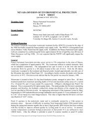
![Adobe PDF File 69 Pages [15MB]](https://img.yumpu.com/18024842/1/190x143/adobe-pdf-file-69-pages-15mb.jpg?quality=85)