ET 200B Distributed I/O Station - DCE FEL ČVUT v Praze
ET 200B Distributed I/O Station - DCE FEL ČVUT v Praze
ET 200B Distributed I/O Station - DCE FEL ČVUT v Praze

You also want an ePaper? Increase the reach of your titles
YUMPU automatically turns print PDFs into web optimized ePapers that Google loves.
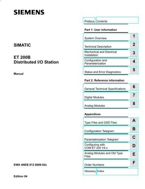
SIMATIC<br />
<strong>ET</strong> <strong>200B</strong><br />
<strong>Distributed</strong> I/O <strong>Station</strong><br />
Manual<br />
EWA 4NEB 812 6089-02c<br />
Edition 04<br />
Preface, Contents<br />
Part 1: User information<br />
System Overview<br />
Technical Description<br />
Mechanical and Electrical<br />
Installation<br />
Configuration and<br />
Parameterization<br />
Status and Error Diagnostics<br />
Part 2: Reference information<br />
General Technical Specifications<br />
Digital Modules<br />
Analog Modules<br />
Appendices<br />
Type Files and GSD Files<br />
Configuration Telegram<br />
Parameterization Telegram<br />
Configuring with<br />
COM <strong>ET</strong> 200 V4.x<br />
Analog Modules and Old Type<br />
Files<br />
Order Numbers<br />
Glossary, Index<br />
1<br />
2<br />
3<br />
4<br />
5<br />
6<br />
7<br />
8<br />
A<br />
B<br />
C<br />
D<br />
E<br />
F
Safety Guidelines<br />
!<br />
!<br />
!<br />
Qualified Personnel<br />
Correct Usage<br />
Trademarks<br />
!<br />
This manual contains notices which you should observe to ensure your own personal safety, as<br />
well as to protect the product and connected equipment. These notices are highlighted in the<br />
manual by a warning triangle and are marked as follows according to the level of danger:<br />
Danger<br />
indicates that death, severe personal injury or substantial property damage will result if proper<br />
precautions are not taken.<br />
Warning<br />
indicates that death, severe personal injury or substantial property damage can result if proper<br />
precautions are not taken.<br />
Caution<br />
indicates that minor personal injury or property damage can result if proper precautions are not taken.<br />
Note<br />
draws your attention to particularly important information on the product, handling the product, or<br />
to a particular part of the documentation.<br />
The device/system may only be set up and operated in conjunction with this manual.<br />
Only qualified personnel should be allowed to install and work on this equipment. Qualified<br />
persons are defined as persons who are authorized to commission, to ground, and to tag circuits,<br />
equipment, and systems in accordance with established safety practices and standards.<br />
Note the following:<br />
Copyright Siemens AG 1995 All rights reserved<br />
Warning<br />
This device and its components may only be used for the applications described in the catalog or the<br />
technical description, and only in connection with devices or components from other manufacturers<br />
which have been approved or recommended by Siemens.<br />
This product can only function correctly and safely if it is transported, stored, set up, and installed<br />
correctly, and operated and maintained as recommended.<br />
SIMATIC and SINEC are registered trademarks of SIEMENS AG.<br />
Some of the other designations used in these documents are also registered trademarks; the owner’s<br />
rights may be violated if they are used be third parties for their own purposes.<br />
The reproduction, transmission or use of this document or its<br />
contents is not permitted without express written authority.<br />
Offenders will be liable for damages. All rights, including rights<br />
created by patent grant or registration of a utility model or design, are<br />
reserved.<br />
Siemens AG<br />
Automation Group<br />
Industrial Automation Systems<br />
P.O. Box 4848, D-90327 Nuremberg<br />
Disclaimer of Liability<br />
We have checked the contents of this manual for agreement with the<br />
hardware and software described. Since deviations cannot be precluded<br />
entirely, we cannot guarantee full agreement. However, the<br />
data in this manual are reviewed regularly and any necessary corrections<br />
included in subsequent editions. Suggestions for improvement<br />
are welcomed.<br />
Technical data subject to change.<br />
Siemens AG 1995<br />
Siemens Aktiengesellschaft Order No. 6ES5 998-4<strong>ET</strong>21<br />
<strong>ET</strong> <strong>200B</strong> <strong>Distributed</strong> I/O <strong>Station</strong>
Preface<br />
Purpose of the<br />
Manual<br />
Contents of the<br />
Manual<br />
Scope of the<br />
Manual<br />
Electronic Manuals<br />
Other Requisite<br />
Manuals<br />
<strong>ET</strong> <strong>200B</strong> <strong>Distributed</strong> I/O <strong>Station</strong><br />
EWA 4NEB 812 6089-02c<br />
The information contained in this manual will allow you:<br />
To install, wire and start up the <strong>ET</strong> <strong>200B</strong> distributed I/O station.<br />
To find module characteristics and technical specifications quickly and<br />
easily.<br />
The following explains the structure of the contents of the manual:<br />
What is the <strong>ET</strong> <strong>200B</strong>? Chap. 1<br />
Which control and display<br />
elements does the <strong>ET</strong> <strong>200B</strong> have?<br />
How is the <strong>ET</strong> <strong>200B</strong> installed?<br />
How do I configure<br />
and parameterize the <strong>ET</strong> <strong>200B</strong>?<br />
Faults?<br />
Technical Specifications?<br />
How are configuration and<br />
parameterization telegrams structured?<br />
Chap. 2<br />
Chap. 3<br />
Chap. 4<br />
Chap. 5<br />
Chap. 6, 7, 8<br />
Which type files do I need? Appendix A<br />
Appendix B, C<br />
This manual describes all the <strong>ET</strong> <strong>200B</strong> modules which can be accessed with<br />
the PROFIBUS-DP bus protocol. These <strong>ET</strong> <strong>200B</strong> modules all have order<br />
numbers starting with 6ES7 (see Section F.1).<br />
This manual is valid for operation of the <strong>ET</strong> <strong>200B</strong> with:<br />
IM 308-B master interface module and COM <strong>ET</strong> 200 V4.x<br />
IM 308-C master interface module and COM <strong>ET</strong> 200 WINDOWS<br />
S7/M7-DP master with PROFIBUS-DP interface and STEP 7<br />
other PROFIBUS-DP masters from Siemens and other vendors.<br />
You can also order the documentation for the <strong>ET</strong> <strong>200B</strong> distributed I/O station<br />
as an electronic manual on CD-ROM.<br />
In addition to this manual, you will also need the manual for the DP master<br />
used (see Appendix F.2).<br />
iii
Preface<br />
Organizational<br />
Conventions<br />
Standards<br />
Courses<br />
Queries<br />
iv<br />
The following organizational conventions are used in this manual to make it<br />
easier for you to find specific information:<br />
At the front of the manual is a complete table of contents, together with a<br />
list of all the figures and tables contained in the manual.<br />
The left-hand column of each page in the individual chapters has headings<br />
to help you find information more quickly.<br />
The Appendix is followed by a glossary containing definitions of the most<br />
important technical terms used in the manual.<br />
At the end of the manual is a detailed index which you can use to refer to<br />
specific sections.<br />
The <strong>ET</strong><strong>200B</strong> distributed I/O station is based on the PROFIBUS standard<br />
(EN 50170, Part 1) and the PROFIBUS-DP standard (EN 50170, Part 3).<br />
Our ”KO-<strong>ET</strong> 200” workshop is the ideal way to get to know the <strong>ET</strong> 200 distributed<br />
I/O system.<br />
If you would like more information, please contact your regional Training<br />
Center or the following address:<br />
Product Marketing for SIMATIC, SINEC and COROS<br />
AUT 951<br />
Frau Lades<br />
Postfach 4848<br />
D-90327 Nürnberg<br />
Tel.: +49 (911) 895-3154<br />
Fax: +49 (911) 895-5021<br />
Please direct all technical queries to your Siemens contact partner in the office<br />
responsible for your area. You can look up the addresses in the manuals<br />
for the CPUs, for example in the ”Siemens Worldwide” appendix of the<br />
manual S7-300 Programmable Controller Hardware and Installation, in catalogs<br />
and in CompuServe (go autforum).<br />
You may prefer to use our hotline support; the number to dial is<br />
+49 (911) 895-7000 (fax 7001).<br />
If you need type files or GSD files, the modem number to dial is<br />
+49 (911) 737972.<br />
If you have any questions or comments on this manual, please complete the<br />
suggestions form and return it to us. You will find this form at the back of the<br />
manual.<br />
<strong>ET</strong> <strong>200B</strong> <strong>Distributed</strong> I/O <strong>Station</strong><br />
EWA 4NEB 812 6089-02c
Contents<br />
1 System Overview<br />
1.1 What is the <strong>ET</strong> 200 <strong>Distributed</strong> I/O System? . . . . . . . . . . . . . . . . . . . . . . . . . 1-2<br />
1.2 What is the <strong>ET</strong> <strong>200B</strong>? . . . . . . . . . . . . . . . . . . . . . . . . . . . . . . . . . . . . . . . . . . . . 1-3<br />
1.2.1 Terminal Block . . . . . . . . . . . . . . . . . . . . . . . . . . . . . . . . . . . . . . . . . . . . . . . . . . . 1-5<br />
1.2.2 Electronics Block . . . . . . . . . . . . . . . . . . . . . . . . . . . . . . . . . . . . . . . . . . . . . . . . . 1-6<br />
2 Technical Description<br />
2.1 Design of the Terminal Block . . . . . . . . . . . . . . . . . . . . . . . . . . . . . . . . . . . . . . 2-2<br />
2.2 Design of the Electronics Block . . . . . . . . . . . . . . . . . . . . . . . . . . . . . . . . . . . . 2-4<br />
3 Mechanical and Electrical Installation<br />
3.1 Installing and Setting the Terminal Block . . . . . . . . . . . . . . . . . . . . . . . . . . . . 3-2<br />
3.2 Installing the Electronics Block . . . . . . . . . . . . . . . . . . . . . . . . . . . . . . . . . . . . . 3-12<br />
3.3 Dismantling the Terminal Block and the Electronics Block . . . . . . . . . . . . . 3-14<br />
3.4 Electrical Installation . . . . . . . . . . . . . . . . . . . . . . . . . . . . . . . . . . . . . . . . . . . . . . 3-16<br />
3.4.1 Grounded Configuration . . . . . . . . . . . . . . . . . . . . . . . . . . . . . . . . . . . . . . . . . . 3-17<br />
3.4.2 Ungrounded Configuration . . . . . . . . . . . . . . . . . . . . . . . . . . . . . . . . . . . . . . . . 3-20<br />
3.5 Wiring the Terminal Block . . . . . . . . . . . . . . . . . . . . . . . . . . . . . . . . . . . . . . . . . 3-22<br />
3.6 Wiring the Bus Interface . . . . . . . . . . . . . . . . . . . . . . . . . . . . . . . . . . . . . . . . . . 3-26<br />
4 Configuration and Parameterization<br />
4.1 Configuration Options . . . . . . . . . . . . . . . . . . . . . . . . . . . . . . . . . . . . . . . . . . . . 4-2<br />
4.2 Requirements for Configuration . . . . . . . . . . . . . . . . . . . . . . . . . . . . . . . . . . . . 4-3<br />
4.3 Where to Find the Requisite Information? . . . . . . . . . . . . . . . . . . . . . . . . . . . 4-5<br />
5 Status and Error Diagnostics<br />
5.1 Possible Response on Startup . . . . . . . . . . . . . . . . . . . . . . . . . . . . . . . . . . . . . 5-2<br />
5.2 Status and Error Indication by LEDs . . . . . . . . . . . . . . . . . . . . . . . . . . . . . . . . 5-3<br />
5.3 Slave Diagnostics . . . . . . . . . . . . . . . . . . . . . . . . . . . . . . . . . . . . . . . . . . . . . . . . 5-5<br />
5.3.1 General Information on Slave Diagnostics, Operation with IM 308-C . . . . 5-6<br />
5.3.2 General Information on Slave Diagnostics, Operation with S7/M7<br />
DP Masters (STEP 7) or Other PROFIBUS-DP Masters . . . . . . . . . . . . . . . 5-8<br />
5.3.3 Structure of Slave Diagnostics . . . . . . . . . . . . . . . . . . . . . . . . . . . . . . . . . . . . . 5-9<br />
5.3.4 Structure of <strong>Station</strong> Status 1 to 3 . . . . . . . . . . . . . . . . . . . . . . . . . . . . . . . . . . . 5-11<br />
5.3.5 Structure of the Master <strong>Station</strong> Number and the Manufacturer ID . . . . . . . 5-13<br />
5.3.6 Structure of Device-Related Diagnostics (Digital <strong>ET</strong> <strong>200B</strong>) . . . . . . . . . . . . . 5-14<br />
5.3.7 Structure of ID-related Diagnostics (Analog <strong>ET</strong> <strong>200B</strong>) . . . . . . . . . . . . . . . . . 5-16<br />
5.3.8 Structure of Device-Related Diagnostics (Analog <strong>ET</strong> <strong>200B</strong>) . . . . . . . . . . . .<br />
5-18<br />
<strong>ET</strong> <strong>200B</strong> <strong>Distributed</strong> I/O <strong>Station</strong><br />
EWA 4NEB 812 6089-02c<br />
v
Contents<br />
6 General Technical Specifications<br />
7 Digital Modules<br />
7.1 Digital Modules . . . . . . . . . . . . . . . . . . . . . . . . . . . . . . . . . . . . . . . . . . . . . . . . . . 7-2<br />
7.2 Terminal Blocks . . . . . . . . . . . . . . . . . . . . . . . . . . . . . . . . . . . . . . . . . . . . . . . . . . 7-4<br />
7.2.1 Terminal Block TB1/DC (6ES7 193-0CA10-0XA0) . . . . . . . . . . . . . . . . . . . . 7-5<br />
7.2.2 Terminal Block TB1-4/DC (6ES7 193-0CA20-0XA0) . . . . . . . . . . . . . . . . . . 7-6<br />
7.2.3 Terminal Block TB3/DC (6ES7 193-0CA30-0XA0) . . . . . . . . . . . . . . . . . . . . 7-7<br />
7.2.4 Terminal Block TB2/DC (6ES7 193-0CB10-0XA0) . . . . . . . . . . . . . . . . . . . . 7-8<br />
7.2.5 Terminal Block TB2-4/DC (6ES7 193-0CB20-0XA0) . . . . . . . . . . . . . . . . . . 7-9<br />
7.2.6 Terminal Block TB4/DC (6ES7 193-0CB30-0XA0) . . . . . . . . . . . . . . . . . . . . 7-10<br />
7.2.7 Terminal Block TB4M/DC (6ES7 193-0CE30-0XA0) . . . . . . . . . . . . . . . . . . 7-11<br />
7.2.8 Terminal Block TB6/AC (6ES7 193-0CC10-0XA0) . . . . . . . . . . . . . . . . . . . . 7-12<br />
7.2.9 Terminal Block and Bus Connector . . . . . . . . . . . . . . . . . . . . . . . . . . . . . . . . . 7-13<br />
7.3 Electronics Blocks . . . . . . . . . . . . . . . . . . . . . . . . . . . . . . . . . . . . . . . . . . . . . . . . 7-14<br />
7.3.1 Electronics Block <strong>ET</strong> <strong>200B</strong>-16DI (6ES7 131-0BH00-0XB0) . . . . . . . . . . . . 7-15<br />
7.3.2 Electronics Blocks <strong>ET</strong> <strong>200B</strong>-32DI (6ES7 131-0BL00-0XB0) and<br />
<strong>ET</strong> <strong>200B</strong>-32DI 0.2ms (6ES7 131-0BL10-0XB0) . . . . . . . . . . . . . . . . . . . . . . 7-20<br />
7.3.3 Electronics Block <strong>ET</strong> <strong>200B</strong>-16DO (6ES7 132-0BH01-0XB0) . . . . . . . . . . . 7-26<br />
7.3.4 Electronics Block <strong>ET</strong> <strong>200B</strong>-16DO/2A (6ES7 132-0BH11-0XB0) . . . . . . . . 7-32<br />
7.3.5 Electronics Block <strong>ET</strong> <strong>200B</strong>-32DO (6ES7 132-0BL01-0XB0) . . . . . . . . . . . . 7-38<br />
7.3.6 Electronics block <strong>ET</strong> <strong>200B</strong>-8RO (6ES7 132-0GF00-0XB0) . . . . . . . . . . . . . 7-44<br />
7.3.7 Electronics Block <strong>ET</strong> <strong>200B</strong>-8DI/8DO (6ES7 133-0BH01-0XB0) . . . . . . . . . 7-49<br />
7.3.8 Electronics Block <strong>ET</strong> <strong>200B</strong>-8DI/8DO HWA (6ES7 133-0BH10-0XB0) . . . . 7-55<br />
7.3.9 Electronics Block <strong>ET</strong> <strong>200B</strong>-16DI/16DO (6ES7 133 0BL00-0XB0) . . . . . . . 7-62<br />
7.3.10 Electronics Blocks <strong>ET</strong> <strong>200B</strong>-24DI/8DO (6ES7 133-0BN01-0XB0) and<br />
<strong>ET</strong> <strong>200B</strong>-24DI/8DO 0.2ms (6ES7 133-0BN11-0XB0) . . . . . . . . . . . . . . . . . . 7-68<br />
7.3.11 Electronics Block <strong>ET</strong> <strong>200B</strong>-16DI-AC (6ES7 131-0HF00-0XB0) . . . . . . . . . 7-74<br />
7.3.12 Electronics Block <strong>ET</strong> <strong>200B</strong>-16DO-AC (6ES7 132-0HF00-0XB0) . . . . . . . . 7-79<br />
7.3.13 Electronics Block <strong>ET</strong> <strong>200B</strong>-16RO-AC (6ES7 132-0HH00-0XB0) . . . . . . . . 7-84<br />
7.3.14 Electronics Block <strong>ET</strong> <strong>200B</strong>-8DI/8RO-AC (6ES7 133-0HH00-0XB0) . . . . . 7-89<br />
8 Analog Modules<br />
8.1 Analog Modules . . . . . . . . . . . . . . . . . . . . . . . . . . . . . . . . . . . . . . . . . . . . . . . . . 8-2<br />
8.2 Terminal Block TB8 (6ES7 193-0CD40-0XA0) . . . . . . . . . . . . . . . . . . . . . . . 8-3<br />
8.3 Terminal Block TB8 and Bus Connector . . . . . . . . . . . . . . . . . . . . . . . . . . . . . 8-4<br />
8.4 Electronics Block <strong>ET</strong> <strong>200B</strong>-4/8AI (6ES7 134-0KH01-0XB0) . . . . . . . . . . . . 8-5<br />
8.4.1 Connecting Transducers . . . . . . . . . . . . . . . . . . . . . . . . . . . . . . . . . . . . . . . . . . 8-7<br />
8.4.2 Configuration Options . . . . . . . . . . . . . . . . . . . . . . . . . . . . . . . . . . . . . . . . . . . . 8-20<br />
8.4.3 Setting the Operating Mode . . . . . . . . . . . . . . . . . . . . . . . . . . . . . . . . . . . . . . . 8-23<br />
8.4.4 Analog Value Representation, Operation with SIMATIC S5 . . . . . . . . . . . . 8-26<br />
8.4.5 Analog Value Representation, Operation with SIMATIC S7 . . . . . . . . . . . . 8-39<br />
8.4.6 Block Diagram, Terminal Assignment and Technical Data . . . . . . . . . . . . . 8-47<br />
8.5 Electronics Block <strong>ET</strong> <strong>200B</strong>-4AI (6ES7 134-0HF01-0XB0) . . . . . . . . . . . . . . 8-51<br />
8.5.1 Connecting Transducers . . . . . . . . . . . . . . . . . . . . . . . . . . . . . . . . . . . . . . . . . . 8-53<br />
8.5.2 Configuration Options . . . . . . . . . . . . . . . . . . . . . . . . . . . . . . . . . . . . . . . . . . . . 8-61<br />
8.5.3 Setting the Operating Mode . . . . . . . . . . . . . . . . . . . . . . . . . . . . . . . . . . . . . . . 8-62<br />
8.5.4 Analog Value Representation, Operation with SIMATIC S5 . . . . . . . . . . . . 8-65<br />
8.5.5 Analog Value Representation, Operation with SIMATIC S7 . . . . . . . . . . . . 8-70<br />
8.5.6 Block Diagram, Terminal Assignment and Technical Data . . . . . . . . . . . . . 8-72<br />
vi<br />
<strong>ET</strong> <strong>200B</strong> <strong>Distributed</strong> I/O <strong>Station</strong><br />
EWA 4NEB 812 6089-02c
8.6 Electronics Block <strong>ET</strong> <strong>200B</strong>-4AO (6ES7 135-0HF01-0XB0) . . . . . . . . . . . . . 8-76<br />
8.6.1 Connecting Loads . . . . . . . . . . . . . . . . . . . . . . . . . . . . . . . . . . . . . . . . . . . . . . . . 8-78<br />
8.6.2 Configuration Options . . . . . . . . . . . . . . . . . . . . . . . . . . . . . . . . . . . . . . . . . . . . 8-82<br />
8.6.3 Setting the Operating Mode . . . . . . . . . . . . . . . . . . . . . . . . . . . . . . . . . . . . . . . 8-83<br />
8.6.4 Analog Value Representation, Operation with SIMATIC S5 . . . . . . . . . . . . 8-85<br />
8.6.5 Analog Value Representation, Operation with SIMATIC S7 . . . . . . . . . . . . 8-87<br />
8.6.6 Block Diagram, Terminal Assignment and Technical Data . . . . . . . . . . . . . 8-89<br />
A Type Files and GSD Files<br />
A.1 Type Files of the <strong>ET</strong> <strong>200B</strong> Modules . . . . . . . . . . . . . . . . . . . . . . . . . . . . . . . . . A-2<br />
A.2 GSD Files of the <strong>ET</strong> <strong>200B</strong> Modules . . . . . . . . . . . . . . . . . . . . . . . . . . . . . . . . . A-4<br />
B Configuration Telegram<br />
C Parameterization Telegram<br />
C.1 Structure of the Parameterization Telegram . . . . . . . . . . . . . . . . . . . . . . . . . . C-2<br />
C.2 Standard Part of the Parameterization Telegram . . . . . . . . . . . . . . . . . . . . . C-3<br />
C.3 Parameters for Status . . . . . . . . . . . . . . . . . . . . . . . . . . . . . . . . . . . . . . . . . . . . C-4<br />
C.4 Parameters for Analog Input Modules . . . . . . . . . . . . . . . . . . . . . . . . . . . . . . . C-5<br />
C.5 Parameters for Analog Output Module . . . . . . . . . . . . . . . . . . . . . . . . . . . . . . C-10<br />
D Configuring with COM <strong>ET</strong> 200 V4.x<br />
D.1 Status and Error Indication by LEDs . . . . . . . . . . . . . . . . . . . . . . . . . . . . . . . . D-2<br />
D.2 Slave Diagnostics . . . . . . . . . . . . . . . . . . . . . . . . . . . . . . . . . . . . . . . . . . . . . . . . D-3<br />
D.2.1 General Information on Slave Diagnostics, Operation with IM 308-B . . . . D-4<br />
D.2.2 Structure of Slave Diagnostics . . . . . . . . . . . . . . . . . . . . . . . . . . . . . . . . . . . . . D-6<br />
D.2.3 Structure of Device-Related Diagnostics (Analog <strong>ET</strong> <strong>200B</strong>) . . . . . . . . . . . . D-8<br />
D.3 Configuration Options . . . . . . . . . . . . . . . . . . . . . . . . . . . . . . . . . . . . . . . . . . . . D-11<br />
D.4 Setting the Operating Mode with COM <strong>ET</strong> 200 V4.x . . . . . . . . . . . . . . . . . . D-12<br />
E Analog Modules and Old Type Files<br />
E.1 Status and Error Indication by LEDs . . . . . . . . . . . . . . . . . . . . . . . . . . . . . . . . E-2<br />
E.2 Structure of Device-Related Diagnostics (Analog <strong>ET</strong> <strong>200B</strong>) . . . . . . . . . . . . E-3<br />
E.3 Configuration Options . . . . . . . . . . . . . . . . . . . . . . . . . . . . . . . . . . . . . . . . . . . . E-7<br />
E.4 Parameters for Analog Modules . . . . . . . . . . . . . . . . . . . . . . . . . . . . . . . . . . . . E-8<br />
F Order Numbers<br />
F.1 Order Numbers for <strong>ET</strong> <strong>200B</strong> Components . . . . . . . . . . . . . . . . . . . . . . . . . . . F-2<br />
F.2 Order Numbers for PROFIBUS-DP Accessories . . . . . . . . . . . . . . . . . . . . . . F-4<br />
<strong>ET</strong> <strong>200B</strong> <strong>Distributed</strong> I/O <strong>Station</strong><br />
EWA 4NEB 812 6089-02c<br />
Contents<br />
vii
Contents<br />
Figures<br />
1-1 Typical PROFIBUS-DP Configuration with SIMATIC S5/S7/M7 . . . . . . . . . 1-2<br />
1-2 Components of <strong>ET</strong> <strong>200B</strong> . . . . . . . . . . . . . . . . . . . . . . . . . . . . . . . . . . . . . . . . . . 1-3<br />
2-1 The TB1/DC . . . . . . . . . . . . . . . . . . . . . . . . . . . . . . . . . . . . . . . . . . . . . . . . . . . . . 2-2<br />
2-2 The TB8 . . . . . . . . . . . . . . . . . . . . . . . . . . . . . . . . . . . . . . . . . . . . . . . . . . . . . . . . 2-3<br />
2-3 <strong>ET</strong> <strong>200B</strong>-16DI Electronics Block . . . . . . . . . . . . . . . . . . . . . . . . . . . . . . . . . . . 2-4<br />
3-1 Clearances Required for Installation of the 16DI, 16DO, 8DI/8DO,<br />
8DI/8DO HWA, 8RO and 4/8AI, 4AI, 4AO Electronics Blocks<br />
(without Shield Connecting Element) . . . . . . . . . . . . . . . . . . . . . . . . . . . . . . . 3-2<br />
3-2 Clearances Required for Installation of the 16DI-AC, 16DO-AC,<br />
32DI, 16DO/2A, 32DO, 16DI/16DO, 24DI/8DO, 16RO-AC and<br />
8DI/8RO-AC Electronics Blocks . . . . . . . . . . . . . . . . . . . . . . . . . . . . . . . . . . . . 3-3<br />
3-3 Clearances Required for Installation of the 4/8AI, 4AI and 4AO<br />
Electronics Blocks (with Shield Connecting Element) . . . . . . . . . . . . . . . . . 3-4<br />
3-4 Hanging the Terminal Block on the Standard Sectional Rail and<br />
Setting the Coding Slide Switch . . . . . . . . . . . . . . . . . . . . . . . . . . . . . . . . . . . . 3-6<br />
3-5 Mounting the Shield Connecting Element on the<br />
Standard Sectional Rail . . . . . . . . . . . . . . . . . . . . . . . . . . . . . . . . . . . . . . . . . . . 3-7<br />
3-6 Mounting the Terminal Block on the Shield Connecting Element . . . . . . . . 3-8<br />
3-7 Changing the Setting of the Coding Plug . . . . . . . . . . . . . . . . . . . . . . . . . . . . 3-10<br />
3-8 Engaging the Electronics Block on the Terminal Block . . . . . . . . . . . . . . . . 3-12<br />
3-9 Dismantling the <strong>ET</strong> <strong>200B</strong> . . . . . . . . . . . . . . . . . . . . . . . . . . . . . . . . . . . . . . . . . . 3-15<br />
3-10 Both Screws Tightened in a Grounded Configuration . . . . . . . . . . . . . . . . . 3-18<br />
3-11 Grounded Configuration for 24 V DC Digital Modules of the <strong>ET</strong> <strong>200B</strong> . . . 3-18<br />
3-12 Grounded Configuration for 120/230 V AC Digital Modules<br />
of the <strong>ET</strong> <strong>200B</strong> . . . . . . . . . . . . . . . . . . . . . . . . . . . . . . . . . . . . . . . . . . . . . . . . . . 3-19<br />
3-13 Upper Screw Removed in an Ungrounded Configuration . . . . . . . . . . . . . . 3-21<br />
3-14 Ungrounded Configuration for 24 V DC Digital Modules of the<br />
<strong>ET</strong> <strong>200B</strong> . . . . . . . . . . . . . . . . . . . . . . . . . . . . . . . . . . . . . . . . . . . . . . . . . . . . . . . . 3-21<br />
3-15 Connecting Cables to Spring-Latch Terminals . . . . . . . . . . . . . . . . . . . . . . . . 3-23<br />
3-16 Shield Connecting Element on Terminal Block TB8 . . . . . . . . . . . . . . . . . . . 3-25<br />
5-1 Structure of Slave Diagnostics for Digital <strong>ET</strong> <strong>200B</strong> . . . . . . . . . . . . . . . . . . . . 5-9<br />
5-2 Structure of Slave Diagnostics for Analog <strong>ET</strong> <strong>200B</strong> . . . . . . . . . . . . . . . . . . . 5-10<br />
5-3 Structure of the Header (Device-Related Diagnostics) for Digital<br />
<strong>ET</strong><strong>200B</strong> (Byte 6) . . . . . . . . . . . . . . . . . . . . . . . . . . . . . . . . . . . . . . . . . . . . . . . . . 5-14<br />
5-4 Structure of Device-Related Diagnostics for Digital<br />
<strong>ET</strong> <strong>200B</strong> (Byte 7) . . . . . . . . . . . . . . . . . . . . . . . . . . . . . . . . . . . . . . . . . . . . . . . . 5-14<br />
5-5 Structure of the Header (ID-related Diagnostics) for Analog<br />
<strong>ET</strong><strong>200B</strong> (Byte 6) . . . . . . . . . . . . . . . . . . . . . . . . . . . . . . . . . . . . . . . . . . . . . . . . . 5-16<br />
5-6 Structure of ID-related Diagnostics for Analog <strong>ET</strong> <strong>200B</strong> (Bytes 7, 8) . . . . 5-16<br />
5-7 Structure of ID-related Diagnostics for Analog <strong>ET</strong> <strong>200B</strong> (Bytes 7, 8)<br />
in the Event of an Error in the Configuration Telegram . . . . . . . . . . . . . . . . 5-17<br />
5-8 Structure of the Header (Device-Related Diagnostics) for Analog<br />
<strong>ET</strong><strong>200B</strong> (Byte 9) . . . . . . . . . . . . . . . . . . . . . . . . . . . . . . . . . . . . . . . . . . . . . . . . . 5-18<br />
5-9 Structure of Device-Related Diagnostics for Analog <strong>ET</strong> <strong>200B</strong><br />
(Bytes 10 to 28) . . . . . . . . . . . . . . . . . . . . . . . . . . . . . . . . . . . . . . . . . . . . . . . . . . 5-19<br />
7-1 Dimensional Drawing: Terminal Block TB1/DC<br />
(Screw-Type Terminal, 3-Tier) . . . . . . . . . . . . . . . . . . . . . . . . . . . . . . . . . . . . . 7-5<br />
7-2 Terminal Numbering: Terminal Block TB1/DC<br />
(Screw-Type Terminal, 3-Tier) . . . . . . . . . . . . . . . . . . . . . . . . . . . . . . . . . . . . . 7-5<br />
7-3 Dimensional Drawing: Terminal Block TB1-4/DC<br />
(Screw-Type Terminal, 4-Tier) . . . . . . . . . . . . . . . . . . . . . . . . . . . . . . . . . . . . . 7-6<br />
viii<br />
<strong>ET</strong> <strong>200B</strong> <strong>Distributed</strong> I/O <strong>Station</strong><br />
EWA 4NEB 812 6089-02c
7-4 Terminal Numbering: Terminal Block TB1-4/DC<br />
(Screw-Type Terminal,4-Tier) . . . . . . . . . . . . . . . . . . . . . . . . . . . . . . . . . . . . . . 7-6<br />
7-5 Dimensional Drawing: Terminal Block TB3/DC<br />
(Spring-Latch Terminal) . . . . . . . . . . . . . . . . . . . . . . . . . . . . . . . . . . . . . . . . . . . 7-7<br />
7-6 Terminal Numbering: Terminal Block TB3/DC<br />
(Spring-Latch Terminal) . . . . . . . . . . . . . . . . . . . . . . . . . . . . . . . . . . . . . . . . . . . 7-7<br />
7-7 Dimensional Drawing: Terminal Block TB2/DC<br />
(Screw-Type Terminal, 3-Tier) . . . . . . . . . . . . . . . . . . . . . . . . . . . . . . . . . . . . . 7-8<br />
7-8 Terminal Numbering: Terminal Block TB2/DC<br />
(Screw-Type Terminal, 3-Tier) . . . . . . . . . . . . . . . . . . . . . . . . . . . . . . . . . . . . . 7-8<br />
7-9 Dimensional Drawing: Terminal Block TB2-4/DC<br />
(Screw-Type Terminal, 4-Tier) . . . . . . . . . . . . . . . . . . . . . . . . . . . . . . . . . . . . . 7-9<br />
7-10 Terminal Numbering: Terminal Block TB2-4/DC<br />
(Screw-Type Terminal, 4-Tier) . . . . . . . . . . . . . . . . . . . . . . . . . . . . . . . . . . . . . 7-9<br />
7-11 Dimensional Drawing: Terminal Block TB4/DC<br />
(Spring-Latch Terminal) . . . . . . . . . . . . . . . . . . . . . . . . . . . . . . . . . . . . . . . . . . . 7-10<br />
7-12 Terminal Numbering: Terminal Block TB4/DC<br />
(Spring-Latch Terminal) . . . . . . . . . . . . . . . . . . . . . . . . . . . . . . . . . . . . . . . . . . . 7-10<br />
7-13 Dimensional Drawing: Terminal Block TB4M/DC<br />
(Spring-Latch Terminal) . . . . . . . . . . . . . . . . . . . . . . . . . . . . . . . . . . . . . . . . . . . 7-11<br />
7-14 Terminal Numbering: Terminal Block TB4M/DC<br />
(Spring-Latch Terminal) . . . . . . . . . . . . . . . . . . . . . . . . . . . . . . . . . . . . . . . . . . . 7-11<br />
7-15 Dimensional Drawing: Terminal Block TB6/AC<br />
(Screw-Type Terminal, 3-Tier) . . . . . . . . . . . . . . . . . . . . . . . . . . . . . . . . . . . . . 7-12<br />
7-16 Terminal Numbering: Terminal Block TB6/AC<br />
(Screw-Type Terminal, 3-Tier) . . . . . . . . . . . . . . . . . . . . . . . . . . . . . . . . . . . . . 7-12<br />
7-17 Dimensional Drawing: Side Elevation with Bus Connector<br />
(6ES7 972-0BA10-0XA0 and 6ES7 972-0BB10-0XA0) . . . . . . . . . . . . . . . . 7-13<br />
7-18 Dimensional Drawing: <strong>ET</strong> <strong>200B</strong>-16DI . . . . . . . . . . . . . . . . . . . . . . . . . . . . . . . 7-15<br />
7-19 Connection Diagram: <strong>ET</strong> <strong>200B</strong>-16DI . . . . . . . . . . . . . . . . . . . . . . . . . . . . . . . . 7-15<br />
7-20 Block Diagram: <strong>ET</strong> <strong>200B</strong>-16DI and TB1/DC or TB3/DC . . . . . . . . . . . . . . . 7-16<br />
7-21 Block Diagram: <strong>ET</strong> <strong>200B</strong>-16DI and TB1-4/DC . . . . . . . . . . . . . . . . . . . . . . . . 7-17<br />
7-22 Dimensional Drawing: <strong>ET</strong> <strong>200B</strong>-32DI and <strong>ET</strong> <strong>200B</strong>-32DI 0.2ms . . . . . . . . 7-20<br />
7-23 Connection Diagram: <strong>ET</strong> <strong>200B</strong>-32DI and <strong>ET</strong> <strong>200B</strong>-32DI 0.2ms . . . . . . . . . 7-20<br />
7-24 Block Diagram: <strong>ET</strong> <strong>200B</strong>-32DI or <strong>ET</strong> <strong>200B</strong>-32DI 0.2ms and<br />
TB2/DC or TB4/DC . . . . . . . . . . . . . . . . . . . . . . . . . . . . . . . . . . . . . . . . . . . . . . . 7-21<br />
7-25 Block Diagram: <strong>ET</strong> <strong>200B</strong>-32DI or <strong>ET</strong> <strong>200B</strong>-32DI 0.2ms and<br />
TB2-4/DC . . . . . . . . . . . . . . . . . . . . . . . . . . . . . . . . . . . . . . . . . . . . . . . . . . . . . . . 7-22<br />
7-26 Front Elevation: <strong>ET</strong> <strong>200B</strong>-16DO . . . . . . . . . . . . . . . . . . . . . . . . . . . . . . . . . . . . 7-26<br />
7-27 Block Diagram: <strong>ET</strong> <strong>200B</strong>-16DO and TB1/DC or TB3/DC . . . . . . . . . . . . . . 7-27<br />
7-28 Block Diagram: <strong>ET</strong> <strong>200B</strong>-16DO and TB1-4/DC . . . . . . . . . . . . . . . . . . . . . . . 7-28<br />
7-29 Front Elevation: <strong>ET</strong> <strong>200B</strong>-16DO/2A . . . . . . . . . . . . . . . . . . . . . . . . . . . . . . . . . 7-32<br />
7-30 Block Diagram: <strong>ET</strong> <strong>200B</strong>-16DO/2A and TB2/DC or TB4/DC . . . . . . . . . . . 7-33<br />
7-31 Block Diagram: <strong>ET</strong> <strong>200B</strong>-16DO/2A and TB2-4/DC . . . . . . . . . . . . . . . . . . . . 7-34<br />
7-32 Front Elevation: <strong>ET</strong> <strong>200B</strong>-32DO . . . . . . . . . . . . . . . . . . . . . . . . . . . . . . . . . . . . 7-38<br />
7-33 Block Diagram: <strong>ET</strong> <strong>200B</strong>-32DO and TB2/DC or TB4/DC . . . . . . . . . . . . . . 7-39<br />
7-34 Block Diagram: <strong>ET</strong> <strong>200B</strong>-32DO and TB2-4/DC . . . . . . . . . . . . . . . . . . . . . . . 7-40<br />
7-35 Front Elevation: <strong>ET</strong> <strong>200B</strong>-8RO . . . . . . . . . . . . . . . . . . . . . . . . . . . . . . . . . . . . . 7-44<br />
7-36 Block Diagram: <strong>ET</strong> <strong>200B</strong>-8RO and TB1/DC or TB3/DC . . . . . . . . . . . . . . . . 7-45<br />
7-37 Block Diagram: <strong>ET</strong> <strong>200B</strong>-8RO and TB1-4/DC . . . . . . . . . . . . . . . . . . . . . . . . 7-46<br />
7-38 Front Elevation: <strong>ET</strong> <strong>200B</strong>-8DI/8DO . . . . . . . . . . . . . . . . . . . . . . . . . . . . . . . . . 7-49<br />
7-39 Block Diagram: <strong>ET</strong> <strong>200B</strong>-8DI/8DO and TB1/DC or TB3/DC . . . . . . . . . . . . 7-50<br />
<strong>ET</strong> <strong>200B</strong> <strong>Distributed</strong> I/O <strong>Station</strong><br />
EWA 4NEB 812 6089-02c<br />
Contents<br />
ix
Contents<br />
x<br />
7-40 Block Diagram: <strong>ET</strong> <strong>200B</strong>-8DI/8DO and TB1-4/DC . . . . . . . . . . . . . . . . . . . . 7-51<br />
7-41 Front Elevation: <strong>ET</strong> <strong>200B</strong>-8DI/8DO HWA . . . . . . . . . . . . . . . . . . . . . . . . . . . . 7-55<br />
7-42 Block Diagram: <strong>ET</strong> <strong>200B</strong>-8DI/8DO HWA and TB1/DC or TB3/DC . . . . . . . 7-56<br />
7-43 Block Diagram: <strong>ET</strong> <strong>200B</strong>-8DI/8DO HWA and TB1-4/DC . . . . . . . . . . . . . . . 7-57<br />
7-44 Front Elevation: <strong>ET</strong> <strong>200B</strong>-16DI/16DO . . . . . . . . . . . . . . . . . . . . . . . . . . . . . . . 7-62<br />
7-45 Block Diagram: <strong>ET</strong> <strong>200B</strong>-16DI/16DO and TB2/DC or TB4/DC . . . . . . . . . . 7-63<br />
7-46 Block Diagram: <strong>ET</strong> <strong>200B</strong>-16DI/16DO and TB2-4/DC . . . . . . . . . . . . . . . . . . 7-64<br />
7-47 Front Elevation: <strong>ET</strong> <strong>200B</strong>-24DI/8DO and <strong>ET</strong> <strong>200B</strong>-24DI/8DO 0.2ms . . . . 7-68<br />
7-48 Block Diagram: <strong>ET</strong> <strong>200B</strong>-24DI/8DO or <strong>ET</strong> <strong>200B</strong>-24DI/8DO 0.2ms<br />
and TB2/DC or TB4/DC . . . . . . . . . . . . . . . . . . . . . . . . . . . . . . . . . . . . . . . . . . . 7-69<br />
7-49 Block Diagram: <strong>ET</strong> <strong>200B</strong>-24DI/8DO or <strong>ET</strong> <strong>200B</strong>-24DI/8DO 0.2ms<br />
and TB2-4/DC . . . . . . . . . . . . . . . . . . . . . . . . . . . . . . . . . . . . . . . . . . . . . . . . . . . 7-70<br />
7-50 Front Elevation: <strong>ET</strong> <strong>200B</strong>-16DI-AC . . . . . . . . . . . . . . . . . . . . . . . . . . . . . . . . . 7-74<br />
7-51 Block Diagram: <strong>ET</strong> <strong>200B</strong>-16DI-AC and TB6/AC . . . . . . . . . . . . . . . . . . . . . . 7-75<br />
7-52 Front Elevation: <strong>ET</strong> <strong>200B</strong>-16DO-AC . . . . . . . . . . . . . . . . . . . . . . . . . . . . . . . . 7-79<br />
7-53 Block Diagram: <strong>ET</strong> <strong>200B</strong>-16DO-AC and TB6/AC . . . . . . . . . . . . . . . . . . . . . 7-80<br />
7-54 Front Elevation: <strong>ET</strong> <strong>200B</strong>-16RO-AC . . . . . . . . . . . . . . . . . . . . . . . . . . . . . . . . 7-84<br />
7-55 Block Diagram: <strong>ET</strong> <strong>200B</strong>-16RO-AC and TB6/AC . . . . . . . . . . . . . . . . . . . . . 7-85<br />
7-56 Front Elevation: <strong>ET</strong> <strong>200B</strong>-8DI/8RO-AC . . . . . . . . . . . . . . . . . . . . . . . . . . . . . . 7-89<br />
7-57 Block Diagram: <strong>ET</strong> <strong>200B</strong>-8DI/8RO-AC and TB6/AC . . . . . . . . . . . . . . . . . . . 7-90<br />
8-1 Dimensional Drawing: Terminal Block TB8 (Spring-Latch Terminals) . . . . 8-3<br />
8-2 Terminal Numbering: Terminal Block TB8 (Spring-Latch Terminals) . . . . . 8-3<br />
8-3 Dimensional Drawing: Side Elevation with Bus Connectors<br />
(6ES7 972-0BA10-0XA0 and 6ES7 972-0BB10-0XA0) . . . . . . . . . . . . . . . . 8-4<br />
8-4 Dimensional Drawing: <strong>ET</strong> <strong>200B</strong>-4/8AI . . . . . . . . . . . . . . . . . . . . . . . . . . . . . . . 8-5<br />
8-5 Connection Diagram: <strong>ET</strong> <strong>200B</strong>-4/8AI . . . . . . . . . . . . . . . . . . . . . . . . . . . . . . . 8-6<br />
8-6 Connection of Thermocouples with one Compensating Box<br />
(Floating- Ground Measurement) . . . . . . . . . . . . . . . . . . . . . . . . . . . . . . . . . . . 8-11<br />
8-7 Connection of Thermocouples with one Compensating Box per<br />
Channel (Floating-Ground Measurement) . . . . . . . . . . . . . . . . . . . . . . . . . . . 8-12<br />
8-8 Connection of Thermocouples with one Compensating Box (Ground-Referenced<br />
Measurement) . . . . . . . . . . . . . . . . . . . . . . . . . . . . . . . . . . . . . . . . . . . . . 8-13<br />
8-9 Connection of Resistance Thermometers (Pt 100) with 2-Wire<br />
Connections (Floating-Ground Measurement) . . . . . . . . . . . . . . . . . . . . . . . 8-14<br />
8-10 Connection of Resistance Thermometers (Pt 100) with 2-Wire<br />
Connections (Ground-Referenced Measurement) . . . . . . . . . . . . . . . . . . . . 8-15<br />
8-11 Connection of Resistance Thermometers (Pt 100) with 4-Wire<br />
Connections (Floating-Ground Measurement) . . . . . . . . . . . . . . . . . . . . . . . 8-16<br />
8-12 Connection of Resistance Thermometers (Pt 100) with 4-Wire<br />
Connections (Ground-Referenced Measurement) . . . . . . . . . . . . . . . . . . . . 8-17<br />
8-13 2-Wire Connection of Voltage Sensors to <strong>ET</strong> <strong>200B</strong>-4/8AI<br />
(Floating-Ground Measurement) . . . . . . . . . . . . . . . . . . . . . . . . . . . . . . . . . . . 8-18<br />
8-14 2-Wire Connection of Voltage Sensors to <strong>ET</strong> <strong>200B</strong>-4/8AI<br />
(Ground-Referenced Measurement) . . . . . . . . . . . . . . . . . . . . . . . . . . . . . . . . 8-19<br />
8-15 Block Diagram: <strong>ET</strong> <strong>200B</strong>-4/8AI and TB8 . . . . . . . . . . . . . . . . . . . . . . . . . . . . 8-47<br />
8-16 Front Elevation: <strong>ET</strong> <strong>200B</strong>-4AI . . . . . . . . . . . . . . . . . . . . . . . . . . . . . . . . . . . . . . 8-51<br />
8-17 Two-Wire Connection of Voltage Sensors to<strong>ET</strong> <strong>200B</strong>-4AI<br />
(Floating-Ground Measurement) . . . . . . . . . . . . . . . . . . . . . . . . . . . . . . . . . . . 8-55<br />
8-18 Two-Wire Connection of Voltage Sensors to <strong>ET</strong> <strong>200B</strong>-4AI<br />
(Ground-Referenced Measurement) . . . . . . . . . . . . . . . . . . . . . . . . . . . . . . . . 8-56<br />
8-19 Two-Wire Connection of Current Sensors<br />
(Floating-Ground Measurement) . . . . . . . . . . . . . . . . . . . . . . . . . . . . . . . . . . . 8-57<br />
<strong>ET</strong> <strong>200B</strong> <strong>Distributed</strong> I/O <strong>Station</strong><br />
EWA 4NEB 812 6089-02c
8-20 Two-Wire Connection of Current Sensors<br />
(Ground-Referenced Measurement) . . . . . . . . . . . . . . . . . . . . . . . . . . . . . . . . 8-58<br />
8-21 Connection of 2-Wire Measuring Transducer as Current Sensor . . . . . . . . 8-59<br />
8-22 Connection of 4-Wire Measuring Transducer as Current Sensor<br />
or Voltage Sensor . . . . . . . . . . . . . . . . . . . . . . . . . . . . . . . . . . . . . . . . . . . . . . . . 8-60<br />
8-23 Block Diagram: <strong>ET</strong> <strong>200B</strong>-4AI and TB8 . . . . . . . . . . . . . . . . . . . . . . . . . . . . . . 8-72<br />
8-24 Front Elevation: <strong>ET</strong> <strong>200B</strong>-4AO . . . . . . . . . . . . . . . . . . . . . . . . . . . . . . . . . . . . . 8-76<br />
8-25 4-Wire Connection of Loads for Voltage Output . . . . . . . . . . . . . . . . . . . . . . 8-79<br />
8-26 2-Wire Connection of Loads for Voltage Output . . . . . . . . . . . . . . . . . . . . . . 8-80<br />
8-27 2-Wire Connection of Loads for Current Output . . . . . . . . . . . . . . . . . . . . . . 8-81<br />
8-28 Block Diagram: <strong>ET</strong> <strong>200B</strong>-4AO and TB8 . . . . . . . . . . . . . . . . . . . . . . . . . . . . . 8-89<br />
C-1 Structure of the Parameterization Telegram for<br />
Digital <strong>ET</strong> <strong>200B</strong> modules . . . . . . . . . . . . . . . . . . . . . . . . . . . . . . . . . . . . . . . . . . C-2<br />
C-2 Structure of the Parameterization Telegram for<br />
Analog <strong>ET</strong> <strong>200B</strong> Modules . . . . . . . . . . . . . . . . . . . . . . . . . . . . . . . . . . . . . . . . . C-2<br />
C-3 Standard Part of the Parameterization Telegram . . . . . . . . . . . . . . . . . . . . . C-3<br />
C-4 Parameters for Status . . . . . . . . . . . . . . . . . . . . . . . . . . . . . . . . . . . . . . . . . . . . C-4<br />
C-5 Parameters for Analog Input Modules 4/8AI, 4AI . . . . . . . . . . . . . . . . . . . . . C-5<br />
C-6 Bytes 15 and 16 for Analog Input Modules 4/8AI, 4AI . . . . . . . . . . . . . . . . . C-6<br />
C-7 Bytes 22 and 35 for Analog Input Modules 4/8AI, 4AI . . . . . . . . . . . . . . . . . C-7<br />
C-8 Parameters for Analog Output Module 4AO . . . . . . . . . . . . . . . . . . . . . . . . . C-10<br />
C-9 Bytes 15 and 16 for Analog Output Module 4AO . . . . . . . . . . . . . . . . . . . . . C-11<br />
C-10 Bytes 22 to 35 for Analog Output Module 4AO . . . . . . . . . . . . . . . . . . . . . . . C-12<br />
D-1 Structure of the Header (Device-Related Diagnostics)<br />
for Analog <strong>ET</strong><strong>200B</strong> . . . . . . . . . . . . . . . . . . . . . . . . . . . . . . . . . . . . . . . . . . . . . . D-8<br />
D-2 Structure of Device-Related Diagnostics for Analog <strong>ET</strong> <strong>200B</strong><br />
(Bytes 7 to 15) . . . . . . . . . . . . . . . . . . . . . . . . . . . . . . . . . . . . . . . . . . . . . . . . . . . D-9<br />
E-1 Structure of the Header (Device-Related Diagnostics)<br />
for Analog <strong>ET</strong><strong>200B</strong> . . . . . . . . . . . . . . . . . . . . . . . . . . . . . . . . . . . . . . . . . . . . . . E-3<br />
E-2 Structure of Device-Related Diagnostics for Analog <strong>ET</strong> <strong>200B</strong><br />
(Bytes 7 to 24) . . . . . . . . . . . . . . . . . . . . . . . . . . . . . . . . . . . . . . . . . . . . . . . . . . . E-4<br />
<strong>ET</strong> <strong>200B</strong> <strong>Distributed</strong> I/O <strong>Station</strong><br />
EWA 4NEB 812 6089-02c<br />
Contents<br />
xi
Contents<br />
Tables<br />
1-1 <strong>ET</strong> <strong>200B</strong>: Range of Applications . . . . . . . . . . . . . . . . . . . . . . . . . . . . . . . . . . . 1-4<br />
3-1 Assignment of the Electronics Blocks to the Coding Slide Switch . . . . . . . 3-9<br />
3-2 Approved Fuses for Terminal Blocks . . . . . . . . . . . . . . . . . . . . . . . . . . . . . . . . 3-11<br />
3-3 Approved Conductor Cross-sections . . . . . . . . . . . . . . . . . . . . . . . . . . . . . . . 3-23<br />
3-4 Pin Assignments of the Terminal Blocks . . . . . . . . . . . . . . . . . . . . . . . . . . . . . 3-24<br />
3-5 Bus Connectors . . . . . . . . . . . . . . . . . . . . . . . . . . . . . . . . . . . . . . . . . . . . . . . . . . 3-26<br />
3-6 Pin Assignment of the PROFIBUS-DP Interface . . . . . . . . . . . . . . . . . . . . . . 3-26<br />
4-1 Type File Versions and Applications . . . . . . . . . . . . . . . . . . . . . . . . . . . . . . . . 4-4<br />
5-1 LEDs on Digital <strong>ET</strong> <strong>200B</strong> Modules and their Meanings . . . . . . . . . . . . . . . . 5-3<br />
5-2 LEDs on Analog <strong>ET</strong> <strong>200B</strong> Modules and their Meanings . . . . . . . . . . . . . . . 5-4<br />
5-3 Function Blocks for Slave Diagnostics . . . . . . . . . . . . . . . . . . . . . . . . . . . . . . 5-10<br />
5-4 Structure of <strong>Station</strong> Status 1 (Byte 0) . . . . . . . . . . . . . . . . . . . . . . . . . . . . . . . 5-11<br />
5-5 Structure of <strong>Station</strong> Status 2 (Byte 1) . . . . . . . . . . . . . . . . . . . . . . . . . . . . . . . 5-11<br />
5-6 Structure of the Master <strong>Station</strong> Number (Byte 3) . . . . . . . . . . . . . . . . . . . . . 5-13<br />
5-7 Structure of the Manufacturer ID (Bytes 4, 5) . . . . . . . . . . . . . . . . . . . . . . . . 5-13<br />
5-8 Bytes 13 to 16 for Diagnostics and Process Alarms . . . . . . . . . . . . . . . . . . 5-19<br />
5-9 Possible Values for Byte 13 in Diagnostics Alarm . . . . . . . . . . . . . . . . . . . . . 5-20<br />
5-10 Bytes 17 to 28 for Diagnostics Alarm . . . . . . . . . . . . . . . . . . . . . . . . . . . . . . . 5-21<br />
5-11 Diagnostics Byte for an Analog Input/Analog Output Channel . . . . . . . . . . 5-21<br />
7-1 <strong>ET</strong> <strong>200B</strong> Digital Electronics Blocks . . . . . . . . . . . . . . . . . . . . . . . . . . . . . . . . . 7-2<br />
7-2 <strong>ET</strong> <strong>200B</strong> Digital Terminal Blocks . . . . . . . . . . . . . . . . . . . . . . . . . . . . . . . . . . . 7-3<br />
7-3 Pin Assignment of Terminal Blocks TB1/DC; TB1-4/DC and TB3/DC<br />
for <strong>ET</strong> <strong>200B</strong>-16DI . . . . . . . . . . . . . . . . . . . . . . . . . . . . . . . . . . . . . . . . . . . . . . . . 7-18<br />
7-4 Pin AssignmentofTerminal<br />
BlocksTB2/DC,TB2-4/DC,TB4/DCandTB4M/DCfor<strong>ET</strong> <strong>200B</strong>-32DI<br />
and <strong>ET</strong> <strong>200B</strong>-32DI 0.2ms . . . . . . . . . . . . . . . . . . . . . . . . . . . . . . . . . . . . . . . . . 7-23<br />
7-5 Pin Assignment of Terminal Blocks TB1/DC, TB1-4/DC and TB3/DC<br />
for <strong>ET</strong> <strong>200B</strong>-16DO . . . . . . . . . . . . . . . . . . . . . . . . . . . . . . . . . . . . . . . . . . . . . . . 7-29<br />
7-6 Pin Assignment of Terminal Blocks TB2/DC; TB2-4/DC, TB4/DC<br />
and TB4M/DC for <strong>ET</strong> <strong>200B</strong>-16DO/2A . . . . . . . . . . . . . . . . . . . . . . . . . . . . . . . 7-35<br />
7-7 Pin Assignment of Terminal Blocks TB2/DC, TB2-4/DC, TB4/DC<br />
and TB4M/DC for <strong>ET</strong> <strong>200B</strong>-32DO . . . . . . . . . . . . . . . . . . . . . . . . . . . . . . . . . . 7-41<br />
7-8 Pin Assignment of Terminal Blocks TB1/DC; TB1-4/DC and TB3/DC<br />
for <strong>ET</strong> <strong>200B</strong>-8RO . . . . . . . . . . . . . . . . . . . . . . . . . . . . . . . . . . . . . . . . . . . . . . . . 7-47<br />
7-9 Pin Assignment of Terminal Blocks TB1/DC; TB1-4/DC and TB3/DC<br />
for <strong>ET</strong> <strong>200B</strong>-8DI/8DO . . . . . . . . . . . . . . . . . . . . . . . . . . . . . . . . . . . . . . . . . . . . . 7-52<br />
7-10 Pin Assignment of Terminal Blocks TB1/DC; TB1-4/DC and TB3/DC<br />
for <strong>ET</strong> <strong>200B</strong>-8DI/8DO HWA . . . . . . . . . . . . . . . . . . . . . . . . . . . . . . . . . . . . . . . . 7-58<br />
7-11 Truth for Hardware Cutoff of <strong>ET</strong> <strong>200B</strong>-8DI/8DO HWA . . . . . . . . . . . . . . . . . 7-59<br />
7-12 Pin Assignment of Terminal Blocks TB2/DC, TB2-4/DC, TB4/DC<br />
and TB4M/DC for <strong>ET</strong> <strong>200B</strong>-16DI/16DO . . . . . . . . . . . . . . . . . . . . . . . . . . . . . 7-65<br />
7-13 Pin Assignment of Terminal Blocks TB2/DC; TB2-4/DC and TB4/DC<br />
for <strong>ET</strong> <strong>200B</strong>-24DI/8DO and <strong>ET</strong> <strong>200B</strong>-24DI/8DO 0.2ms . . . . . . . . . . . . . . . . 7-71<br />
7-14 Pin Assignment of Terminal Block TB6/AC for <strong>ET</strong> <strong>200B</strong>-16DI-AC . . . . . . 7-76<br />
7-15 Pin Assignment of Terminal Block TB6/AC for <strong>ET</strong> <strong>200B</strong>-16DO-AC . . . . . 7-81<br />
7-16 Pin Assignment of Terminal Block TB6/AC for <strong>ET</strong> <strong>200B</strong>-16RO-AC . . . . . 7-86<br />
7-17 Pin Assignment of Terminal Block TB6/AC for <strong>ET</strong> <strong>200B</strong>-8DI/8RO-AC . . . 7-91<br />
8-1 Analog Electronics Blocks of <strong>ET</strong> <strong>200B</strong> . . . . . . . . . . . . . . . . . . . . . . . . . . . . . . 8-2<br />
8-2 Analog Terminal Block of <strong>ET</strong> <strong>200B</strong> . . . . . . . . . . . . . . . . . . . . . . . . . . . . . . . . . 8-2<br />
8-3 Compensating Box Type U with Current Stabilizer. . . . . . . . . . . . . . . . . . . . 8-9<br />
8-4 Reference Junction with Built-in Power Supply Unit . . . . . . . . . . . . . . . . . . . 8-9<br />
xii<br />
<strong>ET</strong> <strong>200B</strong> <strong>Distributed</strong> I/O <strong>Station</strong><br />
EWA 4NEB 812 6089-02c
8-5 Possible Configurations for the Input Areas of <strong>ET</strong> <strong>200B</strong>-4/8AI,<br />
with only Voltage Sensors and Thermocouples Connected . . . . . . . . . . . . 8-20<br />
8-6 Possible IDs for Configuring the Input Areas of <strong>ET</strong> <strong>200B</strong>-4/8AI,<br />
with only Thermal resistors and Resistors Connected . . . . . . . . . . . . . . . . . 8-21<br />
8-7 Example for Configuring the Input Areas of <strong>ET</strong> <strong>200B</strong>-4/8AI . . . . . . . . . . . . 8-22<br />
8-8 Assignment of Terminals to Channel Groups . . . . . . . . . . . . . . . . . . . . . . . . . 8-23<br />
8-9 Parameters for <strong>ET</strong> <strong>200B</strong>-4/8AI (6ES7 134-0KH01-0XB0) . . . . . . . . . . . . . 8-24<br />
8-10 Representation of an Analog Input Value as a Bit Pattern<br />
(6ES7 134-0KH01-0XB0) . . . . . . . . . . . . . . . . . . . . . . . . . . . . . . . . . . . . . . . . . 8-26<br />
8-11 Description of the Bits (6ES7 134-0KH01-0XB0) . . . . . . . . . . . . . . . . . . . . . 8-26<br />
8-12 Representation of Digitized Measured Values of the <strong>ET</strong> <strong>200B</strong>-4/8AI<br />
(Measuring Ranges: 80 mV, 250 mV, 500 mV<br />
and 1000 mV; Complement of Twos) . . . . . . . . . . . . . . . . . . . . . . . . . . . . . 8-27<br />
8-13 Representation of Digitized Measured Values of the <strong>ET</strong> <strong>200B</strong>-4/8AI<br />
(Measuring Ranges: 80 mV, 250 mV, 500 mV and<br />
1000 mV; Amount and Sign) . . . . . . . . . . . . . . . . . . . . . . . . . . . . . . . . . . . . 8-28<br />
8-14 Representation of Digitized Measured Values of the <strong>ET</strong> <strong>200B</strong>-4/8AI<br />
for Resistance Measurement (Complement of Twos) . . . . . . . . . . . . . . . . . 8-29<br />
8-15 Representation of Digitized Measured Values of the <strong>ET</strong> <strong>200B</strong>-4/8AI<br />
for Resistance Thermometers (Complement of Twos) . . . . . . . . . . . . . . . . . 8-30<br />
8-16 Representation of Digitized Measured Values of the <strong>ET</strong> <strong>200B</strong>-4/8AI<br />
for Ni 100 Resistance Sensors (Complement of Twos) . . . . . . . . . . . . . . . . 8-31<br />
8-17 Representation of Digitized Measured Values of the <strong>ET</strong> <strong>200B</strong>-4/8AI<br />
with Linearization; Type E Thermocouples (Nickel-Chrome/<br />
Copper-Nickel, to IEC 548, Part 1; Complement of Twos) . . . . . . . . . . . . . 8-32<br />
8-18 Representation of Digitized Measured Values of the <strong>ET</strong> <strong>200B</strong>-4/8AI<br />
with Linearization: Type J Thermocouple (Iron/Copper-Nickel<br />
(Constantan), to IEC 584) (Complement of Twos) . . . . . . . . . . . . . . . . . . . . 8-33<br />
8-19 Representation of Digitized Measured Values of the <strong>ET</strong> <strong>200B</strong>-4/8AI<br />
with Linearization: Type K Thermocouples (Nickel-Chrome/<br />
Nickel-Aluminum, to IEC 584) (Complement of Twos) . . . . . . . . . . . . . . . . . 8-34<br />
8-20 Representation of Digitized Measured Values of the <strong>ET</strong> <strong>200B</strong>-4/8AI<br />
with Linearization: Type L Thermocouples (Iron/Copper-Nickel<br />
(Constantan), to DIN 43710) (Complement of Twos) . . . . . . . . . . . . . . . . . . 8-35<br />
8-21 Representation of Digitized Measured Values of the <strong>ET</strong> <strong>200B</strong>-4/8AI<br />
with Linearization; Type N Thermocouples (Nickel-Chrome-Silicium/<br />
Nickel-Silicium, to IEC 548-1; Complement of Twos) . . . . . . . . . . . . . . . . . . 8-36<br />
8-22 Representation of Digitized Measured Values of the <strong>ET</strong> <strong>200B</strong>-4/8AI<br />
with Linearization; Type T Thermocouples<br />
(Copper/Copper-Nickel, to IEC 548, Part 1; Complement of Twos) . . . . . . 8-37<br />
8-23 Representation of Digitized Measured Values of the <strong>ET</strong> <strong>200B</strong>-4/8AI<br />
with Linearization; Type U Thermocouples (Copper/Copper-Nickel,<br />
to DIN 43710; Complement of Twos) . . . . . . . . . . . . . . . . . . . . . . . . . . . . . . . 8-38<br />
8-24 Representation of an Analog Input Value as a Bit Pattern for<br />
SIMATIC S7 and <strong>ET</strong> <strong>200B</strong>-4/8AI . . . . . . . . . . . . . . . . . . . . . . . . . . . . . . . . . . . 8-39<br />
8-25 Possible Resolutions of Analog Values: <strong>ET</strong> <strong>200B</strong>-4/8AI . . . . . . . . . . . . . . . 8-39<br />
8-26 Representation of Digitized Measured Values of the <strong>ET</strong> <strong>200B</strong>-4/8AI<br />
(Measuring Ranges: 80 mV, 250 mV, 500 mV<br />
and 1000 mV) . . . . . . . . . . . . . . . . . . . . . . . . . . . . . . . . . . . . . . . . . . . . . . . . . 8-40<br />
8-27 Representation of Digitized Measured Values of the <strong>ET</strong> <strong>200B</strong>-4/8AI<br />
for Resistance Measurement . . . . . . . . . . . . . . . . . . . . . . . . . . . . . . . . . . . . . . 8-41<br />
8-28 Representation of Digitized Measured Values of the <strong>ET</strong> <strong>200B</strong>-4/8AI<br />
<strong>ET</strong> <strong>200B</strong> <strong>Distributed</strong> I/O <strong>Station</strong><br />
EWA 4NEB 812 6089-02c<br />
Contents<br />
xiii
Contents<br />
xiv<br />
for Pt 100 Resistance Sensors . . . . . . . . . . . . . . . . . . . . . . . . . . . . . . . . . . . . . 8-42<br />
8-29 Representation of Digitized Measured Values of the <strong>ET</strong> <strong>200B</strong>-4/8AI<br />
for Ni 100 Resistance Sensors . . . . . . . . . . . . . . . . . . . . . . . . . . . . . . . . . . . . . 8-42<br />
8-30 Representation of Digitized Measured Values of the <strong>ET</strong> <strong>200B</strong>-4/8AI<br />
with Linearization; Type E Thermocouples . . . . . . . . . . . . . . . . . . . . . . . . . . . 8-43<br />
8-31 Representation of Digitized Measured Values of the <strong>ET</strong> <strong>200B</strong>-4/8AI<br />
with Linearization; Type J Thermocouples . . . . . . . . . . . . . . . . . . . . . . . . . . . 8-43<br />
8-32 Representation of Digitized Measured Values of the <strong>ET</strong> <strong>200B</strong>-4/8AI<br />
with Linearization; Type K Thermocouples . . . . . . . . . . . . . . . . . . . . . . . . . . . 8-44<br />
8-33 Representation of Digitized Measured Values of the <strong>ET</strong> <strong>200B</strong>-4/8AI<br />
with Linearization; Type L Thermocouples . . . . . . . . . . . . . . . . . . . . . . . . . . . 8-44<br />
8-34 Representation of Digitized Measured Values of the <strong>ET</strong> <strong>200B</strong>-4/8AI<br />
with Linearization; Type N Thermocouples . . . . . . . . . . . . . . . . . . . . . . . . . . 8-45<br />
8-35 Representation of Digitized Measured Values of the <strong>ET</strong> <strong>200B</strong>-4/8AI<br />
with Linearization; Type T Thermocouples . . . . . . . . . . . . . . . . . . . . . . . . . . . 8-45<br />
8-36 Representation of Digitized Measured Values of the <strong>ET</strong> <strong>200B</strong>-4/8AI<br />
with Linearization; Type U Thermocouples . . . . . . . . . . . . . . . . . . . . . . . . . . 8-46<br />
8-37 Terminal Assignment of the TB8 for <strong>ET</strong> <strong>200B</strong>-4/8AI . . . . . . . . . . . . . . . . . . . 8-48<br />
8-38 Possible Configurations for the Input Areas of <strong>ET</strong> <strong>200B</strong>-4AI . . . . . . . . . . . . 8-61<br />
8-39 Assignment of Terminals to Channels . . . . . . . . . . . . . . . . . . . . . . . . . . . . . . . 8-62<br />
8-40 Parameters for <strong>ET</strong> <strong>200B</strong>-4AI) . . . . . . . . . . . . . . . . . . . . . . . . . . . . . . . . . . . . . 8-63<br />
8-41 Representation of an Analog Input Value as a Bit Pattern<br />
(6ES7 134-0HF01-0XB0) . . . . . . . . . . . . . . . . . . . . . . . . . . . . . . . . . . . . . . . . . 8-65<br />
8-42 Description of the Bits (6ES7 134-0HF01-0XB0) . . . . . . . . . . . . . . . . . . . . . 8-65<br />
8-43 Representation of Digitized Measured Values of the <strong>ET</strong> <strong>200B</strong>-4AI<br />
(Measuring Ranges: 1.25 V, 2.5 V, 5 V, 10 V;<br />
Complement of Twos) . . . . . . . . . . . . . . . . . . . . . . . . . . . . . . . . . . . . . . . . . . . . 8-66<br />
8-44 Representation of Digitized Measured Values of the <strong>ET</strong> <strong>200B</strong>-4AI<br />
(Measuring Ranges: 1.25 V, 2.5 V, 5 V, 10 V;<br />
Amount and Sign) . . . . . . . . . . . . . . . . . . . . . . . . . . . . . . . . . . . . . . . . . . . . . . . . 8-66<br />
8-45 Representation of Digitized Measured Values of the <strong>ET</strong> <strong>200B</strong>-4AI<br />
(Measuring Ranges: 1.25 V, 2.5 V, 5 V, 10 V; Binary) . . . . . . . 8-67<br />
8-46 Representation of Digitized Measured Values of the <strong>ET</strong> <strong>200B</strong>-4AI<br />
(Measuring Range: 20 mA; Complement of Twos) . . . . . . . . . . . . . . . . . 8-67<br />
8-47 Representation of Digitized Measured Values of the <strong>ET</strong> <strong>200B</strong>-4AI<br />
(Measuring Range: 20 mA; Amount and Sign) . . . . . . . . . . . . . . . . . . . . . 8-68<br />
8-49 Representation of Digitized Measured Values of the <strong>ET</strong> <strong>200B</strong>-4AI<br />
(Measuring Range: 0 ... 20 mA) . . . . . . . . . . . . . . . . . . . . . . . . . . . . . . . . . . . . 8-69<br />
8-50 Representation of Digitized Measured Values of the <strong>ET</strong> <strong>200B</strong>-4AI<br />
(Measuring Range: 4 ... 20 mA) . . . . . . . . . . . . . . . . . . . . . . . . . . . . . . . . . . . . 8-69<br />
8-51 Representation of an Analog Input Value as a Bit Pattern for<br />
SIMATIC S7 and <strong>ET</strong> <strong>200B</strong>-4AI . . . . . . . . . . . . . . . . . . . . . . . . . . . . . . . . . . . . . 8-70<br />
8-52 Representation of Digitized Measured Values of the <strong>ET</strong> <strong>200B</strong>-4AI<br />
(Measuring Ranges: 1.25 V, 2.5 V, 5 V and 10 V) . . . . . . . . . . 8-70<br />
8-53 Representation of Digitized Measured Values of the <strong>ET</strong> <strong>200B</strong>-4AI<br />
(Measuring Range: 20 mA) . . . . . . . . . . . . . . . . . . . . . . . . . . . . . . . . . . . . . 8-71<br />
8-54 Representation of Digitized Measured Values of the <strong>ET</strong> <strong>200B</strong>-4AI<br />
(Measuring Ranges: 0 to 20 mA and 4 to 20 mA) . . . . . . . . . . . . . . . . . . . . . 8-71<br />
8-55 Terminal Assignment of the TB8 for <strong>ET</strong> <strong>200B</strong>-4AI . . . . . . . . . . . . . . . . . . . . . 8-73<br />
8-56 Possible Configurations for the Output Areas of <strong>ET</strong> <strong>200B</strong>-4AO . . . . . . . . . 8-82<br />
8-57 Assignment of Terminals to Channels . . . . . . . . . . . . . . . . . . . . . . . . . . . . . . . 8-83<br />
8-58 Parameters for <strong>ET</strong> <strong>200B</strong>-4AO . . . . . . . . . . . . . . . . . . . . . . . . . . . . . . . . . . . . . . 8-84<br />
<strong>ET</strong> <strong>200B</strong> <strong>Distributed</strong> I/O <strong>Station</strong><br />
EWA 4NEB 812 6089-02c
8-59 Representation of an Analog Output Value as a Bit Pattern<br />
(6ES7 135-0HF01-0XB0) . . . . . . . . . . . . . . . . . . . . . . . . . . . . . . . . . . . . . . . . . 8-85<br />
8-60 Description of the Bits (6ES7 135-0HF01-0XB0) . . . . . . . . . . . . . . . . . . . . . 8-85<br />
8-61 Analog Output Signals of the <strong>ET</strong> <strong>200B</strong>-4AO (Value Ranges:<br />
10 V, 0 ... 10 V, 20 mA, 0 ... 20 mA, 4 ... 20 mA;<br />
Complement of Twos) . . . . . . . . . . . . . . . . . . . . . . . . . . . . . . . . . . . . . . . . . . . . 8-86<br />
8-62 Representation of an Analog Output Value as a Bit Pattern for<br />
SIMATIC S7 and <strong>ET</strong> <strong>200B</strong>-4AO . . . . . . . . . . . . . . . . . . . . . . . . . . . . . . . . . . . . 8-87<br />
8-63 Representation of Digitized Measured Values of the <strong>ET</strong> <strong>200B</strong>-4AO<br />
(Output Ranges: 0 to 10 V and 10 V) . . . . . . . . . . . . . . . . . . . . . . . . . . . . . 8-87<br />
8-64 Representation of Digitized Measured Values of the <strong>ET</strong> <strong>200B</strong>-4AO<br />
(Output Ranges: 20 mA, 0 to 20 mA and 4 to 20 mA) . . . . . . . . . . . . . . . 8-88<br />
8-65 Terminal Assignment of the TB8 for <strong>ET</strong> <strong>200B</strong>-4AO . . . . . . . . . . . . . . . . . . . . 8-90<br />
A-1 Designations of Type Files for Digital Modules . . . . . . . . . . . . . . . . . . . . . . . A-2<br />
A-2 Designations of Type Files for Analog Modules . . . . . . . . . . . . . . . . . . . . . . A-3<br />
A-3 Characteristics according to EN 50170, Part 3 for<br />
<strong>ET</strong> <strong>200B</strong>-16DI, <strong>ET</strong> <strong>200B</strong>-32DI, <strong>ET</strong> <strong>200B</strong>-32DI 0.2ms,<br />
<strong>ET</strong> <strong>200B</strong>-16DO, <strong>ET</strong> <strong>200B</strong>-16DO/2A . . . . . . . . . . . . . . . . . . . . . . . . . . . . . . . . A-5<br />
A-4 Characteristics according to EN 50170, Part 3 for <strong>ET</strong> <strong>200B</strong>-32DO,<br />
<strong>ET</strong> <strong>200B</strong>-8RO, <strong>ET</strong> <strong>200B</strong>-8DI/8DO, <strong>ET</strong> <strong>200B</strong>-8DI/8DO HWA . . . . . . . . . . . A-6<br />
A-5 Characteristics according to EN 50170, Part 3 for <strong>ET</strong> <strong>200B</strong>-16DI/16DO,<br />
<strong>ET</strong> <strong>200B</strong>-24DI/8DO, <strong>ET</strong> <strong>200B</strong>-24DI/8DO 0.2ms . . . . . . . . . . . . . . . . . . . . . . A-7<br />
A-6 Characteristics according to EN 50170, Part 3 for <strong>ET</strong> <strong>200B</strong>-16DI-AC,<br />
<strong>ET</strong> <strong>200B</strong>-16DO-AC, <strong>ET</strong> <strong>200B</strong>-16RO-AC, <strong>ET</strong> <strong>200B</strong>-8DI/8RO-AC . . . . . . . . A-8<br />
A-7 Characteristics according to EN 50170, Part 3 for <strong>ET</strong> <strong>200B</strong>-4/8AI,<br />
<strong>ET</strong> <strong>200B</strong>-4AI, <strong>ET</strong> <strong>200B</strong>-4AO . . . . . . . . . . . . . . . . . . . . . . . . . . . . . . . . . . . . . . . A-9<br />
B-1 Structure of the Configuration Telegram for Digital <strong>ET</strong> <strong>200B</strong> Modules . . . B-2<br />
B-2 IDs for Digital <strong>ET</strong> <strong>200B</strong> Modules . . . . . . . . . . . . . . . . . . . . . . . . . . . . . . . . . . . B-2<br />
B-3 Structure of the Configuration Telegram for Analog <strong>ET</strong> <strong>200B</strong> Modules . . . B-3<br />
B-4 IDs for Analog <strong>ET</strong> <strong>200B</strong> Modules . . . . . . . . . . . . . . . . . . . . . . . . . . . . . . . . . . B-3<br />
C-1 Assignment of Terminals to Channel (Groups) . . . . . . . . . . . . . . . . . . . . . . . C-5<br />
C-2 Codings for the Integration Times of the 4/8AI . . . . . . . . . . . . . . . . . . . . . . . C-8<br />
C-3 Codings for the Measuring Ranges of the Analog Input Modules . . . . . . . C-8<br />
C-4 Assignment of Terminals to Channels . . . . . . . . . . . . . . . . . . . . . . . . . . . . . . . C-10<br />
C-5 Codings for Output Ranges of the Analog Output Module . . . . . . . . . . . . . C-13<br />
D-1 LEDs on Analog <strong>ET</strong> <strong>200B</strong> Modules and their Meanings . . . . . . . . . . . . . . . D-2<br />
D-2 Structure of Slave Diagnostics for Digital <strong>ET</strong> <strong>200B</strong>,<br />
Operation with IM 308-B . . . . . . . . . . . . . . . . . . . . . . . . . . . . . . . . . . . . . . . . . . D-6<br />
D-3 Structure of Slave Diagnostics for Analog <strong>ET</strong> <strong>200B</strong>,<br />
Operation with IM 308-B . . . . . . . . . . . . . . . . . . . . . . . . . . . . . . . . . . . . . . . . . . D-7<br />
D-4 Diagnostics Data, Bytes 9 to 12 . . . . . . . . . . . . . . . . . . . . . . . . . . . . . . . . . . . . D-9<br />
D-5 Possible Values for Byte 9 . . . . . . . . . . . . . . . . . . . . . . . . . . . . . . . . . . . . . . . . . D-10<br />
D-6 Diagnostics Data, Bytes 13 to 15 . . . . . . . . . . . . . . . . . . . . . . . . . . . . . . . . . . . D-10<br />
D-7 IDs for <strong>ET</strong> <strong>200B</strong> . . . . . . . . . . . . . . . . . . . . . . . . . . . . . . . . . . . . . . . . . . . . . . . . . . D-11<br />
D-8 Content and Meanings of the Bytes in the<br />
Parameterization Telegram . . . . . . . . . . . . . . . . . . . . . . . . . . . . . . . . . . . . . . . D-13<br />
E-1 LEDs on Analog <strong>ET</strong> <strong>200B</strong> Modules and their Meanings . . . . . . . . . . . . . . . E-2<br />
E-2 Diagnostics Data, Bytes 9 to 12 . . . . . . . . . . . . . . . . . . . . . . . . . . . . . . . . . . . . E-4<br />
E-3 Possible Values for Byte 9 . . . . . . . . . . . . . . . . . . . . . . . . . . . . . . . . . . . . . . . . . E-5<br />
E-4 Bytes 13 to 16 for Diagnostics Alarm . . . . . . . . . . . . . . . . . . . . . . . . . . . . . . . E-5<br />
E-5 Diagnostics Byte for an Analog Input/Analog Output Channel . . . . . . . . . . E-6<br />
E-6 Possible IDs for Configuring Input and Output and Areas . . . . . . . . . . . . . . E-7<br />
<strong>ET</strong> <strong>200B</strong> <strong>Distributed</strong> I/O <strong>Station</strong><br />
EWA 4NEB 812 6089-02c<br />
Contents<br />
xv
Contents<br />
xvi<br />
E-7 Parameters for <strong>ET</strong> <strong>200B</strong>-4/8AI (6ES7 134-0KH01-0XB0) . . . . . . . . . . . . . E-8<br />
E-8 Parameters for <strong>ET</strong> <strong>200B</strong>-4AI (6ES7 134-0HF01-0XB0) . . . . . . . . . . . . . . . E-9<br />
E-9 Parameters for <strong>ET</strong> <strong>200B</strong>-4AO (6ES7 135-0HF01-0XB0) . . . . . . . . . . . . . . . E-10<br />
F-1 Order Numbers, Electronics Blocks for <strong>ET</strong> <strong>200B</strong> . . . . . . . . . . . . . . . . . . . . . F-2<br />
F-2 Order Numbers, Terminal Blocks for <strong>ET</strong> <strong>200B</strong> . . . . . . . . . . . . . . . . . . . . . . . . F-3<br />
F-3 Order Numbers, Labeling Strips . . . . . . . . . . . . . . . . . . . . . . . . . . . . . . . . . . . . F-3<br />
F-4 Accessories for the <strong>ET</strong> 200 <strong>Distributed</strong> I/O System . . . . . . . . . . . . . . . . . . . F-4<br />
F-5 Manuals for <strong>ET</strong> 200 in SIMATIC S5 . . . . . . . . . . . . . . . . . . . . . . . . . . . . . . . . . F-5<br />
F-6 Manuals for STEP 7 and SIMATIC S7 . . . . . . . . . . . . . . . . . . . . . . . . . . . . . . F-5<br />
<strong>ET</strong> <strong>200B</strong> <strong>Distributed</strong> I/O <strong>Station</strong><br />
EWA 4NEB 812 6089-02c
System Overview<br />
In this Chapter<br />
<strong>ET</strong> <strong>200B</strong> <strong>Distributed</strong> I/O <strong>Station</strong><br />
EWA 4NEB 812 6089-02c<br />
The System Overview gives you information on the following:<br />
1<br />
In Section you will find on Page<br />
1.1 What is the <strong>ET</strong> 200 distributed I/O system? 1-2<br />
1.2 What is <strong>ET</strong> <strong>200B</strong>? 1-3<br />
1-1
1<br />
System Overview<br />
1.1 What is the <strong>ET</strong> 200 <strong>Distributed</strong> I/O System?<br />
Definition<br />
The Components<br />
of <strong>ET</strong> 200<br />
1-2<br />
DP master<br />
PROFIBUS-DP<br />
DP slaves<br />
S5-115/135/155U<br />
The <strong>ET</strong> 200 distributed I/O system is based on the PROFIBUS standard<br />
(EN 50170, Part 1) and the PROFIBUS-DP standard (EN 50170, Part 3).<br />
The field bus on which the <strong>ET</strong> 200 distributed I/O system is based is a version<br />
of PROFIBUS known as PROFIBUS-DP (DP = Dezentrale Peripherie, or<br />
distributed I/O). This version is designed for minimum reaction times in<br />
communication with the distributed inputs and outputs.<br />
The distributed input/output system consists of active stations (DP masters)<br />
and passive stations (DP slaves) interconnected by the PROFIBUS-DP field<br />
bus.<br />
S7-300/M7-300 S7-400/M7-400 S5-95U PG/PC<br />
<strong>ET</strong> <strong>200B</strong> <strong>ET</strong> 200C <strong>ET</strong> 200M S5-95U<br />
Figure 1-1 Typical PROFIBUS-DP Configuration with SIMATIC S5/S7/M7<br />
SINEC L2-DP =<br />
PROFIBUS-DP<br />
SINEC L2-DP is the PROFIBUS-DP from Siemens.<br />
STEP 7<br />
COM <strong>ET</strong> 200<br />
Field devices<br />
<strong>ET</strong> <strong>200B</strong> <strong>Distributed</strong> I/O <strong>Station</strong><br />
EWA 4NEB 812 6089-02c
1.2 What is the <strong>ET</strong> <strong>200B</strong>?<br />
Definition<br />
Range of Modules<br />
Application<br />
Components<br />
<strong>ET</strong> <strong>200B</strong> <strong>Distributed</strong> I/O <strong>Station</strong><br />
EWA 4NEB 812 6089-02c<br />
The <strong>ET</strong> <strong>200B</strong> (B stands for ”block I/O”) belongs to the <strong>ET</strong> 200 distributed<br />
I/O system with the PROFIBUS-DP field bus. <strong>ET</strong> <strong>200B</strong> is a DP slave having<br />
IP 20 protection.<br />
The <strong>ET</strong> <strong>200B</strong> distributed I/O station incorporates an integral port for connection<br />
to the PROFIBUS-DP bus and digital or analog inputs/outputs.<br />
The range of modules for the <strong>ET</strong> <strong>200B</strong> includes:<br />
24 V DC digital modules<br />
120/230 V AC digital modules<br />
Analog modules<br />
Thanks to its compact and flat design, the <strong>ET</strong> <strong>200B</strong> distributed I/O station is<br />
primarily suited to applications where space is a priority.<br />
The <strong>ET</strong> <strong>200B</strong> distributed I/O station can be mounted either on a standard sectional<br />
rail or directly onto the wall. Vertical and horizontal installation are<br />
both possible.<br />
The <strong>ET</strong> <strong>200B</strong> consists of 2 parts: the terminal block and the electronics<br />
block.<br />
The terminal block (TB) incorporates the permanent wiring and does not contain<br />
any function-related electrical components. The electronics block is attached<br />
to the terminal block. The electronics block (EB) contains the logic<br />
circuits.<br />
The terminal block and the electronics block have matching mechanical coding<br />
elements to prevent destruction of the electronics block.<br />
Electronics block<br />
Terminal block<br />
Figure 1-2 Components of <strong>ET</strong> <strong>200B</strong><br />
+<br />
=<br />
System Overview<br />
<strong>ET</strong> <strong>200B</strong><br />
1-3<br />
1
1<br />
System Overview<br />
Compatible with<br />
S7 Slave<br />
The Next Sections<br />
1-4<br />
All <strong>ET</strong> <strong>200B</strong> modules can be addressed with the PROFIBUS-DP bus protocol.<br />
<strong>ET</strong> <strong>200B</strong> can be operated with the following systems:<br />
Table 1-1 <strong>ET</strong> <strong>200B</strong>: Range of Applications<br />
In system Operating with Configurable with<br />
SIMATIC S5 IM 308-B master interface (release<br />
5 and higher)<br />
IM 308-C master interface (release<br />
1 and higher)<br />
SIMATIC S7/M7 S7/M7 DP master with integral<br />
PROFIBUS-DP interface<br />
COM <strong>ET</strong> 200 V4.x<br />
version 4.0 and higher:<br />
digital modules<br />
version 4.1 and higher:<br />
analog modules<br />
COM <strong>ET</strong> 200 Windows<br />
(version 1.0 and higher)<br />
STEP 7<br />
version 2.0 and higher:<br />
digital modules<br />
version 3.0 and higher:<br />
analog modules<br />
Theanalog modules of <strong>ET</strong><strong>200B</strong> can be operated as S7 slaves in conjunction<br />
with SIMATIC S7/ M7 and STEP 7 (V3.0 and higher). This means that all the<br />
functions of the central S7 I/O modules are also at your disposal for the<br />
<strong>ET</strong> <strong>200B</strong> analog modules.<br />
The next sections of this chapter contain an overview of the components of<br />
<strong>ET</strong> <strong>200B</strong>.<br />
In Section you will find on Page<br />
1.2.1 Terminal Block 1-5<br />
1.2.2 Electronics Block 1-6<br />
<strong>ET</strong> <strong>200B</strong> <strong>Distributed</strong> I/O <strong>Station</strong><br />
EWA 4NEB 812 6089-02c
1.2.1 Terminal Block<br />
Definition<br />
Characteristics<br />
<strong>ET</strong> <strong>200B</strong> <strong>Distributed</strong> I/O <strong>Station</strong><br />
EWA 4NEB 812 6089-02c<br />
The terminal block incorporates the permanent wiring.<br />
The terminal block has the following characteristics:<br />
System Overview<br />
The supply voltage for the electronics block (logic) can be switched on/<br />
off (except for the TB6/AC terminal block).<br />
The terminal block can be mounted both on standard sectional rails and<br />
on smooth surfaces, so direct wall mounting is possible.<br />
The PROFIBUS-DP bus is interfaced via a SINEC L2 bus connector.<br />
<strong>Station</strong> numbers between 00 and 99 can be set with the aid of a tool such<br />
as a screwdriver:<br />
– When operating with an IM 308-B master interface, station numbers<br />
3 to 99 are permissible.<br />
– When operating with an IM 308-C master interface or with an S7/M7<br />
DP master, station numbers 1 to 99 are permissible.<br />
1-5<br />
1
1<br />
System Overview<br />
1.2.2 Electronics Block<br />
Definition<br />
Characteristics<br />
1-6<br />
The electronics block contains the logic circuits and is plugged onto the terminal<br />
block.<br />
The electronics block has the following characteristics:<br />
There is galvanic isolation between the PROFIBUS-DP bus and the internal<br />
electronics.<br />
The block has LEDs for indicating the following:<br />
– Voltage supply to the logic circuits (RUN)<br />
– Bus fault (BF)<br />
– Group diagnostics: short-circuit, wire break or load voltage failure<br />
(DIA, only for electronics blocks which can be diagnosed)<br />
– Load voltage monitoring (L1+, L2+, L3+, L4+, only for digital electronics<br />
blocks (24 V DC) with output channels)<br />
– Status of the inputs or outputs (for digital electronics blocks only)<br />
Labeling strips are inserted in the electronics block. Fill in the labeling<br />
strips to ensure unambiguous assignment of name, channel and LED.<br />
<strong>ET</strong> <strong>200B</strong> <strong>Distributed</strong> I/O <strong>Station</strong><br />
EWA 4NEB 812 6089-02c
Technical Description<br />
In this Chapter<br />
<strong>ET</strong> <strong>200B</strong> <strong>Distributed</strong> I/O <strong>Station</strong><br />
EWA 4NEB 812 6089-02c<br />
This chapter contains information on:<br />
2<br />
In Section you will find on Page<br />
2.1 Design of the Terminal Block 2-2<br />
2.2 Design of the Electronics Block 2-4<br />
2-1
2<br />
Technical Description<br />
2.1 Design of the Terminal Block<br />
Design Principle of<br />
the Digital TBs<br />
2-2<br />
All digital terminal blocks are built on the same design principle explained<br />
below using the TB1/DC terminal block as a typical example:<br />
10<br />
9<br />
8<br />
Figure 2-1 The TB1/DC<br />
7<br />
1<br />
1 Coding slide switch<br />
2 Fuse<br />
3 STOP/RUN switch (not TB6/AC). The power supply for logic circuits<br />
in the electronics block can be switched on or off with the STOP/RUN<br />
switch. It can also be used to switch the <strong>ET</strong> <strong>200B</strong> distributed I/O station<br />
on and off.<br />
4 Terminals for power supplies<br />
5 Terminals for inputs/outputs<br />
6 Slide for removing the terminal block from the standard sectional rail<br />
7 M4 screw (connects chassis to PE)<br />
8 M5 screw for connecting PE<br />
9 PROFIBUS-DP interface<br />
10 Switch for setting the station number (the station number is valid only<br />
after operation of the STOP/RUN switch (STOP –> RUN)).<br />
6<br />
5<br />
4<br />
<strong>ET</strong> <strong>200B</strong> <strong>Distributed</strong> I/O <strong>Station</strong><br />
EWA 4NEB 812 6089-02c<br />
2<br />
3
Design Principle of<br />
the TB8 Analog<br />
Block<br />
<strong>ET</strong> <strong>200B</strong> <strong>Distributed</strong> I/O <strong>Station</strong><br />
EWA 4NEB 812 6089-02c<br />
On the front of the TB8 analog terminal block, there are an additional 5 coding<br />
switches:<br />
10<br />
9<br />
8<br />
Figure 2-2 The TB8<br />
7<br />
1 Coding slide switch<br />
2 Fuse<br />
3 STOP/RUN switch. The power supply for logic circuits in the electronics<br />
block can be switched on or off with the STOP/RUN switch. It can<br />
also be used to switch the <strong>ET</strong> <strong>200B</strong> distributed I/O station on and off.<br />
4 Terminals for power supplies<br />
5 Terminals for inputs/outputs<br />
6 Slide for removing the terminal block from the standard sectional rail<br />
7 Coding connectors. You use the coding connectors to set the wiring of<br />
the TB8 for analog value processing.<br />
8 M5 screw for connecting PE<br />
9 PROFIBUS-DP interface<br />
10 Switch for setting the station number (the station number is valid only<br />
after operation of the STOP/RUN switch (STOP –> RUN)).<br />
1<br />
6<br />
5<br />
Technical Description<br />
4<br />
2<br />
3<br />
2-3<br />
2
2<br />
Technical Description<br />
2.2 Design of the Electronics Block<br />
Design Principle<br />
Coding<br />
2-4<br />
All types of electronics block are built on the same design principle which is<br />
explained below using the <strong>ET</strong> <strong>200B</strong>-16DI electronics block as a typical example:<br />
6<br />
5<br />
4<br />
Figure 2-3 <strong>ET</strong> <strong>200B</strong>-16DI Electronics Block<br />
3<br />
1 Ventilation slots<br />
2 Screws for mounting the electronics block on the terminal block<br />
3 Printed schematic diagram<br />
4 Indication of the coding slide switch setting on the top of the terminal<br />
block<br />
5 Labeling strip; for indicating the status of the inputs or outputs in the<br />
case of digital electronics blocks with LEDs<br />
6 LEDs for<br />
Voltage supply to the logic circuits (RUN)<br />
Bus fault (BF)<br />
Group diagnostics; short-circuit, wire break or load voltage failure<br />
(DIA, only for electronics blocks which can be diagnosed)<br />
Load voltage monitor (L1+, L2+, L3+, L4+, depending on the electronics<br />
block: see Section 5.2)<br />
The electronics blocks are coded by the manufacturer.<br />
Some types of electronics blocks have a recess at the bottom. This recess<br />
ensures that the terminal block is assigned safely to the correct electronics<br />
block.<br />
2<br />
<strong>ET</strong> <strong>200B</strong> <strong>Distributed</strong> I/O <strong>Station</strong><br />
EWA 4NEB 812 6089-02c<br />
1
Mechanical and Electrical Installation<br />
In the Chapter<br />
Technical Data<br />
<strong>ET</strong> <strong>200B</strong> <strong>Distributed</strong> I/O <strong>Station</strong><br />
EWA 4NEB 812 6089-02c<br />
This chapter contains information on:<br />
In Section you will find on Page<br />
3.1 Installing and Setting the Terminal Block 3-2<br />
3.2 Installing the Electronics Block 3-12<br />
3.3 Dismantling the Terminal Block and Electronics Block 3-14<br />
3.4 Electrical Installation 3-16<br />
3.5 Wiring the Terminal Block 3-22<br />
3.6 Wiring the Bus Interface 3-26<br />
You will find a detailed description of the technical data of the <strong>ET</strong> <strong>200B</strong><br />
modules in Sections 6, 7 and 8.<br />
3<br />
3-1
3<br />
Mechanical and Electrical Installation<br />
3.1 Installing and Setting the Terminal Block<br />
Two Methods<br />
Small Electronics<br />
Block, Digital<br />
3-2<br />
You can install the terminal block either<br />
on a standard sectional rail (35 15 mm or 35 7.5 mm to<br />
DIN EN 50022)<br />
or<br />
on smooth surfaces, i.e. direct wall mounting (for dimensions of the<br />
mounting holes see Dimensional Drawings in Sections 7 and 8).<br />
Figure 3-1 shows the clearances required for installation of the 16DI, 16DO,<br />
8DI/8DO, 8DI/8DO HWA, 8RO and 4/8AI, 4AI, 4AO electronics blocks<br />
(without shield connecting element):<br />
Handling and heat dissipation<br />
For swiveling/disengaging the electronics block<br />
Figure 3-1 Clearances Required for Installation of the 16DI, 16DO, 8DI/8DO, 8DI/8DO HWA, 8RO and 4/8AI,<br />
4AI, 4AO Electronics Blocks (without Shield Connecting Element)<br />
<strong>ET</strong> <strong>200B</strong> <strong>Distributed</strong> I/O <strong>Station</strong><br />
EWA 4NEB 812 6089-02c
Large Electronics<br />
Block<br />
<strong>ET</strong> <strong>200B</strong> <strong>Distributed</strong> I/O <strong>Station</strong><br />
EWA 4NEB 812 6089-02c<br />
Figure 3-2 shows the clearances required for installation of the 16DI-AC,<br />
16DO-AC, 32DI, 16DO/2A, 32DO, 16DI/16DO, 24DI/8DO, 16RO-AC and<br />
8DI/8RO-AC electronics blocks:<br />
Handling and heat dissipation<br />
For swiveling/disengaging the electronics block<br />
Mechanical and Electrical Installation<br />
Figure 3-2 Clearances Required for Installation of the 16DI-AC, 16DO-AC, 32DI, 16DO/2A, 32DO, 16DI/16DO,<br />
24DI/8DO, 16RO-AC and 8DI/8RO-AC Electronics Blocks<br />
3-3<br />
3
3<br />
Mechanical and Electrical Installation<br />
Small Electronics<br />
Block, Analog<br />
3-4<br />
Figure 3-3 shows the clearances required for installation of the 4/8AI, 4AI,<br />
4AO electronics blocks (with shield connecting element):<br />
Handling and heat dissipation<br />
For swiveling/disengaging the electronics block<br />
Figure 3-3 Clearances Required for Installation of the 4/8AI, 4AI and 4AO Electronics Blocks (with Shield<br />
Connecting Element)<br />
<strong>ET</strong> <strong>200B</strong> <strong>Distributed</strong> I/O <strong>Station</strong><br />
EWA 4NEB 812 6089-02c
Shield Connecting<br />
Element for TB8<br />
<strong>ET</strong> <strong>200B</strong> <strong>Distributed</strong> I/O <strong>Station</strong><br />
EWA 4NEB 812 6089-02c<br />
Mechanical and Electrical Installation<br />
In the case of analog value processing, we recommend that the cable shielding<br />
of the signal lines be connected directly at terminal block TB8.<br />
For this application, you can hang the TB8 onto a shield connecting element<br />
after first mounting the shield connecting element on a standard sectional rail<br />
(35 15 or 35 7.5 mm to DIN EN 50022) or a smooth surface.<br />
To secure the shield braiding, install metal terminal elements on the shield<br />
connecting element.<br />
You can order the shield connecting element and the terminal elements under<br />
the following numbers:<br />
Shield connecting element → Order No. 6ES7 193-0CD40-7XA0<br />
Terminal elements (set of two):<br />
– Single version → Order No. 6ES7 390-5BA00-0AA0<br />
(one shield cable per terminal element with a diameter of 3 to 8 mm to<br />
be clamped)<br />
– Double version → Order No. 6ES7 390-5AB00-0AA0<br />
(two shield cables per terminal element with a diameter of 2 to 6 mm<br />
to be clamped)<br />
Note<br />
If you mount the TB8 with shield connecting element on a standard sectional<br />
rail, you must install the <strong>ET</strong> <strong>200B</strong> horizontally.<br />
3-5<br />
3
3<br />
Mechanical and Electrical Installation<br />
Mounting on a<br />
Standard Sectional<br />
Rail<br />
3-6<br />
To mount the terminal block on a standard sectional rail...<br />
1. Hang the terminal block on the standard sectional rail (1) and<br />
2. Swing it back until the slide on the module snaps into place (2).<br />
Note:<br />
The meanings of the coding switch settings are explained in Table 3-1.<br />
Figure 3-4 Hanging the Terminal Block on the Standard Sectional Rail and Setting the<br />
Coding Slide Switch<br />
<strong>ET</strong> <strong>200B</strong> <strong>Distributed</strong> I/O <strong>Station</strong><br />
EWA 4NEB 812 6089-02c
Mounting the<br />
Shield Connecting<br />
Element on a Standard<br />
Sectional Rail<br />
<strong>ET</strong> <strong>200B</strong> <strong>Distributed</strong> I/O <strong>Station</strong><br />
EWA 4NEB 812 6089-02c<br />
To mount the shield connecting element on a standard sectional rail...<br />
1. Hang the shield connecting element on the standard sectional rail from<br />
below (1) and swing it back (2).<br />
2. Secure the shield connecting element on the standard sectional rail by<br />
tightening the screws (3).<br />
1<br />
2<br />
Mechanical and Electrical Installation<br />
Figure 3-5 Mounting the Shield Connecting Element on the Standard Sectional Rail<br />
3<br />
3<br />
3-7<br />
3
3<br />
Mechanical and Electrical Installation<br />
Mounting the Terminal<br />
Block on the<br />
Shield Connecting<br />
Element<br />
3-8<br />
To mount the terminal block on the shield connecting element ...<br />
1. Engage the terminal block in the brackets of the terminal connecting element<br />
(1).<br />
2. Tighten the screws to secure the terminal block to the shield connecting<br />
element (2).<br />
1<br />
Figure 3-6 Mounting the Terminal Block on the Shield Connecting Element<br />
2<br />
2<br />
2<br />
<strong>ET</strong> <strong>200B</strong> <strong>Distributed</strong> I/O <strong>Station</strong><br />
EWA 4NEB 812 6089-02c
Setting the Coding<br />
Slide Switch<br />
Setting the <strong>Station</strong><br />
Number<br />
Setting the Coding<br />
Plug<br />
<strong>ET</strong> <strong>200B</strong> <strong>Distributed</strong> I/O <strong>Station</strong><br />
EWA 4NEB 812 6089-02c<br />
Mechanical and Electrical Installation<br />
In order to prevent the wrong electronics block being plugged in, the terminal<br />
block has a coding slide switch (see Section 2.1, Figure 2-1, 1).<br />
The coding switch can be engaged in 6 settings. Each setting is assigned to a<br />
module class of the <strong>ET</strong> <strong>200B</strong> distributed I/O station:<br />
Table 3-1 Assignment of the Electronics Blocks to the Coding Slide Switch<br />
Setting Module Class<br />
1 24 V digital modules<br />
2 24 V special modules<br />
3 Analog modules<br />
4 Reserved<br />
5 Reserved<br />
6 230 V digital modules<br />
Any station number from 00 to 99 can be set with the aid of a tool such as a<br />
screwdriver (see Section 2.1, Figure 2-1, 10):<br />
<strong>Station</strong> numbers 3 to 99 are permissible when operating with the<br />
IM308-B master interface.<br />
<strong>Station</strong> numbers 1 to 99 are permissible when operating with the<br />
IM 308-C master interface or with the S7/M7 DP master.<br />
The station number becomes valid only after a STOP/RUN transition of the<br />
<strong>ET</strong> <strong>200B</strong> slave station.<br />
The coding plus of the TB8 provide the means of setting the defaults for analog<br />
value measurement and analog value output for each channel in the case<br />
of analog modules (see Section 2-1, Figure 2-2, 7).<br />
The coding plugs enable you to set the input or output circuitry of the TB8 to<br />
suit the measured value sensor or load connected and the desired measuring<br />
or output method.<br />
The possible settings for the coding plugs are: ”A”, ”B”, ”C” and ”D”.<br />
The relationships between the various settings of the coding plugs and the<br />
measurement/output method and the measured value sensors and loads are<br />
detailed in the sections dealing with the individual electronics blocks (see<br />
Sections 8.4 through 8.6). The procedure for changing the settings of the coding<br />
plugs is described below.<br />
3-9<br />
3
3<br />
Mechanical and Electrical Installation<br />
Changing the Coding<br />
Plug Setting<br />
3-10<br />
The procedure for changing the setting of a coding plug is as follows:<br />
1. Pull the coding plug above the channel group from its socket in the TB8<br />
(1).<br />
Tip:<br />
It is easiest to reset the coding plugs before installing the electronics<br />
block.<br />
2. Turn the coding plug to the appropriate position (2) and reinsert the coding<br />
plug in its socket (3).<br />
Correct setting:<br />
The pointer ”Δ” beside the letter ”A”, ”B”, ”C” or ”D” must point toward<br />
the electronics block.<br />
1<br />
Figure 3-7 Changing the Setting of the Coding Plug<br />
2<br />
3<br />
<strong>ET</strong> <strong>200B</strong> <strong>Distributed</strong> I/O <strong>Station</strong><br />
EWA 4NEB 812 6089-02c
Terminal Block<br />
Fuses<br />
Changing the Fuse<br />
Approved Fuses<br />
<strong>ET</strong> <strong>200B</strong> <strong>Distributed</strong> I/O <strong>Station</strong><br />
EWA 4NEB 812 6089-02c<br />
The fuse (F1) in the terminal block protects against:<br />
short-circuit in the sensor supply<br />
reversed polarity of the voltage supply to the internal logic<br />
voltage spikes in the voltage supply to the internal logic<br />
If the fuse trips the module’s internal logic is deenergized.<br />
Proceed as follows when changing the fuse:<br />
1. Switch the STOP/RUN switch to the “STOP” position.<br />
2. Pull the electronics block off the terminal block.<br />
3. Pry the fuse out of its base using a screwdriver.<br />
4. Insert the new fuse.<br />
5. Reinstall the electronics block on the terminal block.<br />
6. Switch the RUN/STOP switch to “RUN”.<br />
Note<br />
The TB6/AC terminal block has no STOP/RUN switch. Make sure that the<br />
external power supply is switched off before removing the electronics block<br />
and changing the fuse.<br />
Install only the fuses listed in Table 3-2. The fuses can be ordered in packs of<br />
ten.<br />
Table 3-2 Approved Fuses for Terminal Blocks<br />
Terminal<br />
Block<br />
Fuse Order No.<br />
(pack of 10)<br />
TB6/AC Miniature fuse TR5-T 1.0; 250 V AC 6ES7 193-0DC00-0XA0<br />
TB1/DC Miniature fuse TR5-T 1.6; 250 V 6ES7 193-0DA00-0XA0<br />
TB1-4/DC Miniature fuse TR5-T 1.6; 250 V<br />
TB3/DC Miniature fuse TR5-T 1.6; 250 V<br />
TB8-analog Miniature fuse TR5-T 1.6; 250 V<br />
TB2/DC Miniature fuse TR5-T 2.5; 250 V 6ES7 193-0DB00-0XA0<br />
TB2-4/DC Miniature fuse TR5-T 2.5; 250 V<br />
TB4/DC Miniature fuse TR5-T 2.5; 250 V<br />
TB4M/DC Miniature fuse TR5-T 2.5; 250 V<br />
Mechanical and Electrical Installation<br />
3-11<br />
3
3<br />
Mechanical and Electrical Installation<br />
3.2 Installing the Electronics Block<br />
Engaging the Electronics<br />
Block on<br />
the Terminal Block<br />
3-12<br />
!<br />
After coding the terminal block via the coding slide switch, you can engage<br />
the electronics block on the terminal block:<br />
Warning<br />
Avoid electrical destruction of the electronics block.<br />
Always set the STOP/RUN switch of the terminal block to the “STOP” position<br />
before engaging the electronics block on the terminal block!<br />
The TB6/DC terminal block has no STOP/RUN switch. Always switch off<br />
the external power supply before attempting to engage an electronics block<br />
(120/230 V AC) onto the TB6/DC.<br />
1. Engage the electronics block on the terminal block (1).<br />
2. Press the electronics block onto the terminal block (2).<br />
3. Secure the electronics block by tightening the screws (3).<br />
Figure 3-8 Engaging the Electronics Block on the Terminal Block<br />
<strong>ET</strong> <strong>200B</strong> <strong>Distributed</strong> I/O <strong>Station</strong><br />
EWA 4NEB 812 6089-02c
Labeling the Electronics<br />
Block<br />
<strong>ET</strong> <strong>200B</strong> <strong>Distributed</strong> I/O <strong>Station</strong><br />
EWA 4NEB 812 6089-02c<br />
Mechanical and Electrical Installation<br />
A labeling strip is inserted in the electronics block.<br />
Individual DIN A4 sheets consisting of several labeling strips can be ordered<br />
separately. Please refer to Appendix F for order numbers.<br />
Versions<br />
For electronics blocks with 16DI, 16DO, 8DI/8DO, 8DI/8DO HWA, 8RO,<br />
4/8AI, 4AI, 4AO:<br />
10 labeling strips on one DIN A4 sheet<br />
For electronics blocks with 16DI-AC, 16DO-AC, 32DI, 16DO/2A, 32DO,<br />
16DI/16DO, 24DI/8DO, 16RO-AC, 8DI/8RO-AC:<br />
7 large labeling strips and 9 small labeling strips on one DIN A4 sheet.<br />
3-13<br />
3
3<br />
Mechanical and Electrical Installation<br />
3.3 DismantlingtheTerminalBlockandtheElectronicsBlock<br />
Dismantling<br />
(from the Standard<br />
Sectional Rail)<br />
3-14<br />
!<br />
Proceed according to the following steps:<br />
1. Remove the electronics block in the reverse sequence to that described in<br />
Figure 3-8.<br />
Warning<br />
Avoid electrical destruction of the electronics block.<br />
Always set the STOP/RUN switch of the terminal block to the “STOP” position<br />
before disengaging the electronics block from the terminal block or<br />
installing a replacement electronics block!<br />
The TB6/DC terminal block has no STOP/RUN switch. Always switch off<br />
the external power supply before attempting to disengage an electronics<br />
block (120/230 V AC) from the TB6/DC or installing a replacement electronics<br />
block.<br />
2. Press the slide (1) on the bottom of the terminal block down using a<br />
screwdriver and<br />
3. Swing the terminal block out of the standard sectional rail (2).<br />
2<br />
Figure 3-9 Dismantling the <strong>ET</strong> <strong>200B</strong><br />
1<br />
<strong>ET</strong> <strong>200B</strong> <strong>Distributed</strong> I/O <strong>Station</strong><br />
EWA 4NEB 812 6089-02c
Dismantling<br />
(from the Shield<br />
Connecting Element)<br />
!<br />
<strong>ET</strong> <strong>200B</strong> <strong>Distributed</strong> I/O <strong>Station</strong><br />
EWA 4NEB 812 6089-02c<br />
Mechanical and Electrical Installation<br />
Proceed according to the following steps:<br />
1. Remove the electronics block in the reverse sequence to that described in<br />
Figure 3-8.<br />
Warning<br />
Avoid electrical destruction of the electronics block.<br />
Always set the STOP/RUN switch of the terminal block to the “STOP” position<br />
before disengaging the electronics block from the terminal block or<br />
installing a replacement electronics block!<br />
The TB6/DC terminal block has no STOP/RUN switch. Always switch off<br />
the external power supply before attempting to disengage an electronics<br />
block (120/230 V AC) from the TB6/DC or installing a replacement electronics<br />
block.<br />
2. Remove the terminal block and the shield connecting element in the reverse<br />
sequence to that described in Figures 3-5 and 3-6.<br />
3-15<br />
3
3<br />
Mechanical and Electrical Installation<br />
3.4 Electrical Installation<br />
Introduction<br />
Next Sections<br />
3-16<br />
The <strong>ET</strong> <strong>200B</strong> distributed I/O station allows both grounded and ungrounded<br />
configurations.<br />
The following two sections explain the configuration rules and give circuit<br />
examples for<br />
In Section you will find on Page<br />
3.4.1 Grounded Configuration 3-17<br />
3.4.2 Ungrounded Configuration 3-20<br />
The numbers in the text cross-reference the components shown in the figures.<br />
<strong>ET</strong> <strong>200B</strong> <strong>Distributed</strong> I/O <strong>Station</strong><br />
EWA 4NEB 812 6089-02c
3.4.1 Grounded Configuration<br />
Definition<br />
Rules<br />
<strong>ET</strong> <strong>200B</strong> <strong>Distributed</strong> I/O <strong>Station</strong><br />
EWA 4NEB 812 6089-02c<br />
Mechanical and Electrical Installation<br />
In a grounded configuration, the reference potential of the <strong>ET</strong> <strong>200B</strong> logic<br />
circuits and the protective ground conductor (PE) are galvanically interconnected.<br />
You must note the following points for a grounded configuration:<br />
You must provide a main switch (1) in accordance with DIN VDE 0100<br />
for the <strong>ET</strong> <strong>200B</strong> modules, the signal sensors and the actuators.<br />
If the spur lines are a maximum of 3 m long and are ground-fault-resistant<br />
and short-circuit-proof, the supply connection for the <strong>ET</strong> <strong>200B</strong> and the<br />
load circuit requires no additional fuse (2).<br />
Use a Siemens load power supply unit (3) in the 6EV1 series<br />
(Catalog <strong>ET</strong> 1) for supplying the 24 V DC to the <strong>ET</strong> <strong>200B</strong>.<br />
If you connect another load power supply unit (24 V DC), please note that<br />
the voltage must be in the range 20 to 30 V (including ripple). The load<br />
power supply unit must generate a functional low voltage with safe electrical<br />
isolation in accordance with DIN VDE 0106. In the case of non-stabilized<br />
load power supply units, you require a back-up capacitor (rating<br />
200 F per 1 A load current).<br />
Provide a detachable connection to the protective ground conductor (4) in<br />
the secondary circuit of the load power supply unit (M terminal).<br />
A fuse (5) is required for fusing the supply voltage.<br />
For both grounded and ungrounded configurations, the PE terminal of<br />
the <strong>ET</strong> <strong>200B</strong> must have a low-impedance connection to the protective<br />
ground conductor or the cabinet ground (machine parts) (6).<br />
Use a minimum cross-section of 4 mm2 and a maximum of 10 mm2 for<br />
equipotential bonding and ground connections.<br />
All machine parts must be grounded.<br />
The PROFIBUS-DP interface of terminal blocks release 2 and later is<br />
ungrounded.<br />
3-17<br />
3
3<br />
Mechanical and Electrical Installation<br />
Connecting the<br />
Reference Potential<br />
of the Logic<br />
Circuits to PE<br />
Electrical Configuration<br />
3-18<br />
For a grounded configuration, you must also do the following at the digital<br />
terminal blocks:<br />
1. Connect the PE terminal to the lower screw.<br />
2. Tighten the upper screw. The upper screw connects the ground potential<br />
to PE.<br />
PE<br />
Figure 3-10 Both Screws Tightened in a Grounded Configuration<br />
The following figure shows the grounded configuration for 24 V DC digital<br />
modules of the <strong>ET</strong> <strong>200B</strong>:<br />
L1<br />
L2<br />
L3<br />
N<br />
PE<br />
(1)<br />
(4)<br />
(2)<br />
M L+<br />
M L+<br />
(3)<br />
(5)<br />
(6)<br />
Sensor/<br />
actuator<br />
<strong>ET</strong> <strong>200B</strong><br />
Figure 3-11 Grounded Configuration for 24 V DC Digital Modules of the <strong>ET</strong> <strong>200B</strong><br />
I/O<br />
L+<br />
M<br />
<strong>ET</strong> <strong>200B</strong> <strong>Distributed</strong> I/O <strong>Station</strong><br />
EWA 4NEB 812 6089-02c
Electrical Configuration<br />
<strong>ET</strong> <strong>200B</strong> <strong>Distributed</strong> I/O <strong>Station</strong><br />
EWA 4NEB 812 6089-02c<br />
The following figure shows the grounded configuration for 120/230 V AC<br />
digital modules of the <strong>ET</strong> <strong>200B</strong>:<br />
L1<br />
L2<br />
L3<br />
N<br />
PE<br />
(1)<br />
(8)<br />
230 V AC<br />
(2)<br />
(5)<br />
Mechanical and Electrical Installation<br />
(6)<br />
Sensor/<br />
actuator<br />
<strong>ET</strong> <strong>200B</strong><br />
Figure 3-12 Grounded Configuration for 120/230 V AC Digital Modules of<br />
the <strong>ET</strong> <strong>200B</strong><br />
I/O<br />
L1<br />
N<br />
3-19<br />
3
3<br />
Mechanical and Electrical Installation<br />
3.4.2 Ungrounded Configuration<br />
Definition<br />
Rules<br />
3-20<br />
!<br />
In an ungrounded configuration, there is no galvanic connection between the<br />
reference potential of the <strong>ET</strong> <strong>200B</strong> logic circuits and the protective ground<br />
conductor (PE).<br />
You must note the following points for an ungrounded configuration:<br />
You must provide a main switch (1) in accordance with DIN VDE 0100<br />
for the <strong>ET</strong> <strong>200B</strong> modules, the signal sensors and the actuators.<br />
If the spur lines are a maximum of 3 m long and are ground-fault-resistant<br />
and short-circuit-proof, the supply connection for the <strong>ET</strong> <strong>200B</strong> and the<br />
load circuit requires no additional fuse (2).<br />
Use a Siemens load power supply unit (3) in the 6EV1 series<br />
(Catalog <strong>ET</strong> 1) for supplying the 24 V DC to the <strong>ET</strong> <strong>200B</strong>.<br />
If you connect another load power supply unit (24 V DC), please note that<br />
the voltage must be in the range 20 to 30 V (including ripple). The load<br />
power supply unit must generate a functional low voltage with safe electrical<br />
isolation in accordance with DIN VDE 0106. In the case of non-stabilized<br />
load power supply units, you require a back-up capacitor (rating<br />
200 F per 1 A load current).<br />
A fuse (5) is required for fusing the supply voltage.<br />
For both grounded and ungrounded configurations, the PE terminal of<br />
the <strong>ET</strong> <strong>200B</strong> must have a low-impedance connection to the protective<br />
ground conductor or the cabinet ground (machine parts) (core cross-section<br />
of PE min. 4 mm 2 and max. 10 mm 2 ) (6).<br />
Provide an insulation monitoring circuit against ground with voltage limitation<br />
in accordance with the regulations applying to the system, for<br />
example DIN VDE 0160 (7).<br />
The PROFIBUS-DP interface of terminal blocks release 2 and later is<br />
ungrounded.<br />
Warning<br />
The ungrounded configuration can be canceled out by grounded machine<br />
parts and grounded electrical equipment.<br />
Example: A grounded sensor or a grounded actuator connects the PE to the<br />
reference potential (M terminal) of the controller.<br />
<strong>ET</strong> <strong>200B</strong> <strong>Distributed</strong> I/O <strong>Station</strong><br />
EWA 4NEB 812 6089-02c
Disconnecting the<br />
Reference Potential<br />
of the Logic<br />
Circuits from PE<br />
Electrical Configuration<br />
<strong>ET</strong> <strong>200B</strong> <strong>Distributed</strong> I/O <strong>Station</strong><br />
EWA 4NEB 812 6089-02c<br />
For an ungrounded configuration, you must also do the following at the digital<br />
terminal blocks:<br />
1. Connect the PE terminal to the lower screw.<br />
2. Remove the upper screw for an ungrounded configuration.<br />
Removed<br />
PE<br />
Figure 3-13 Upper Screw Removed in an Ungrounded Configuration<br />
Figure 3-14 shows the ungrounded configuration for 24 V DC digital modules<br />
of the <strong>ET</strong> <strong>200B</strong>:<br />
L1<br />
L2<br />
L3<br />
N<br />
PE<br />
(1)<br />
(7) > VCM (2)<br />
M L+<br />
M L+<br />
(3)<br />
(5)<br />
Mechanical and Electrical Installation<br />
(6)<br />
Sensor/<br />
actuator<br />
<strong>ET</strong> <strong>200B</strong><br />
Figure 3-14 Ungrounded Configuration for 24 V DC Digital Modules of the<br />
<strong>ET</strong> <strong>200B</strong><br />
I/O<br />
L+<br />
M<br />
3-21<br />
3
3<br />
Mechanical and Electrical Installation<br />
3.5 Wiring the Terminal Block<br />
Introduction<br />
Wiring<br />
Floating Electronics<br />
Block<br />
Non-Floating Electronics<br />
Blocks<br />
3-22<br />
Connect the following to the terminal block:<br />
Supply voltage for internal logic circuits<br />
Sensor supply for input channels<br />
Load voltage supply for output channels<br />
Sensors/loads<br />
The wiring of the terminal block is dependent on the electronics block used.<br />
A distinction is made between floating and non-floating electronics blocks.<br />
In a floating electronics block<br />
either the circuit for the internal electronics and the load circuit are galvanically<br />
isolated from each other:<br />
All 120/230 V AC electronics blocks and floating 24 V DC electronics<br />
blocks belong to this category.<br />
or the voltage supply of the internal logic and the analog circuits are galvanically<br />
isolated from each other:<br />
All analog electronics blocks belong to this category.<br />
Note<br />
You can use floating electronics blocks regardless of whether the reference<br />
potential of the supply voltage for the internal logic circuits is grounded or<br />
not.<br />
In non-floating electronics blocks, the internal logic circuits and the load current<br />
circuit share a common reference potential (M ground).<br />
Non-floating electronics blocks include: non-floating 24 V DC electronics<br />
blocks.<br />
<strong>ET</strong> <strong>200B</strong> <strong>Distributed</strong> I/O <strong>Station</strong><br />
EWA 4NEB 812 6089-02c
Conductor Crosssections<br />
Connections<br />
<strong>ET</strong> <strong>200B</strong> <strong>Distributed</strong> I/O <strong>Station</strong><br />
EWA 4NEB 812 6089-02c<br />
The approved conductor cross-sections for all voltage-supply and signal lines<br />
are as follows:<br />
Table 3-3 Approved Conductor Cross-sections<br />
Line Conductor Ferrules Conductor Cross-section<br />
Supply-voltage and sig- with ferrules max. 1.5 mm<br />
nal lines<br />
2<br />
nal lines<br />
w/o ferrules max. 2.5 mm2 (min. 0.08 mm2 for TB3, TB4,<br />
TB4M, TB8 and min. 0.14 mm2 for TB1, TB1-4, TB2, TB2-4)<br />
Protective earth (PE) to<br />
terminal block*<br />
* for TB1-4/DC or TB2-4/DC only<br />
with ferrule max. 2.5 mm 2<br />
Some terminal blocks are fitted with screw terminals while others have<br />
spring-latch terminals (see Figure 3-15) for securing the cable conductors.<br />
Figure 3-15 Connecting Cables to Spring-Latch Terminals<br />
Mechanical and Electrical Installation<br />
2<br />
1<br />
3-23<br />
3
3<br />
Mechanical and Electrical Installation<br />
Pin Assignments<br />
3-24<br />
In Chapter 7 “Range of Modules”, you will find the pin assignments of each<br />
electronics block. The following table will help you.<br />
Table 3-4 Pin Assignments of the Terminal Blocks<br />
Assignment of ... For Electronics Block ... See ...<br />
TB1/DC, TB1-4/DC and <strong>ET</strong> <strong>200B</strong>-16DI Table 7-3<br />
TB3/DC<br />
<strong>ET</strong> <strong>200B</strong>-16DO Table 7-5<br />
<strong>ET</strong> <strong>200B</strong>-8DI/8DO Table 7-9<br />
<strong>ET</strong> <strong>200B</strong>-8DI/8DO HWA Table 7-10<br />
<strong>ET</strong> <strong>200B</strong>-8RO Table 7-8<br />
TB2/DC, TB2-4/DC, <strong>ET</strong> <strong>200B</strong>-16DO/2A Table 7-6<br />
TB4/DC and TB4M/DC<br />
<strong>ET</strong> <strong>200B</strong>-32DI,<br />
<strong>ET</strong> <strong>200B</strong>-32DI 0.2ms<br />
Table 7-4<br />
<strong>ET</strong> <strong>200B</strong>-32DO Table 7-7<br />
<strong>ET</strong> <strong>200B</strong>-16DI/16DO Table 7-12<br />
<strong>ET</strong> <strong>200B</strong>-24DI/8DO,<br />
<strong>ET</strong> <strong>200B</strong>-24DI/8DO 0.2ms<br />
Table 7-13<br />
TB6/AC <strong>ET</strong> <strong>200B</strong>-16DI-AC Table 7-14<br />
<strong>ET</strong> <strong>200B</strong>-16DO-AC Table 7-15<br />
<strong>ET</strong> <strong>200B</strong>-16RO-AC Table 7-16<br />
<strong>ET</strong> <strong>200B</strong>-8DI/8RO-AC Table 7-17<br />
TB8-analog <strong>ET</strong> <strong>200B</strong>-4/8AI Table 8-37<br />
<strong>ET</strong> <strong>200B</strong>-4AI Table 8-55<br />
<strong>ET</strong> <strong>200B</strong>-4AO Table 8-65<br />
<strong>ET</strong> <strong>200B</strong> <strong>Distributed</strong> I/O <strong>Station</strong><br />
EWA 4NEB 812 6089-02c
Shielding for Analog<br />
Value Processing<br />
Procedure for Connecting<br />
the Shielding<br />
<strong>ET</strong> <strong>200B</strong> <strong>Distributed</strong> I/O <strong>Station</strong><br />
EWA 4NEB 812 6089-02c<br />
For analog value processing, connect the cable shields of the signal lines directly<br />
at the TB8 to the shield connecting element (Order No.:<br />
6ES7 193-0CD40-7XA0).<br />
Follow the steps listed below:<br />
1. Engage the TB8 terminal block on the shield connecting element after<br />
first mounting the shield connecting element on the standard sectional rail<br />
or a smooth surface (wall) (see Section 3.1).<br />
2. Mount the metallic terminal elements (see Section 3.1) on the bottom<br />
edge of the shield connecting element (1 and 2).<br />
3. Strip the ends of the signal lines.<br />
4. Secure the bare cable ends to the terminal elements (3 and 4).<br />
5. Connect the shield connecting element to the protective ground conductor<br />
(PE). The cross-section of PE must be a minimum of 4 mm2 and a maximum<br />
of 10 mm2 .<br />
6. Connect the shield of the bus cable in such a way that the maximum bend<br />
radius when bent once (10 x dO; dO = outer diameter of the cable) is not<br />
exceeded.<br />
1<br />
2<br />
2<br />
–0031<br />
<strong>ET</strong><br />
PE<br />
Figure 3-16 Shield Connecting Element on Terminal Block TB8<br />
Mechanical and Electrical Installation<br />
4<br />
4<br />
3<br />
3-25<br />
3
3<br />
Mechanical and Electrical Installation<br />
3.6 Wiring the Bus Interface<br />
Bus Interface<br />
Bus Connector<br />
PROFIBUS-DP Interface<br />
3-26<br />
The PROFIBUS-DP bus connects to the terminal block by means of a bus<br />
connector.<br />
There are a number of bus connectors for <strong>ET</strong> <strong>200B</strong>.<br />
Table 3-5 Bus Connectors<br />
Design Order Number<br />
max. 12 Mbaud without programmer<br />
socket<br />
6ES7 972-0BA10-0XA01 max. 1.5 Mbaud<br />
(without terminating resistor)<br />
with programmer socket 6ES7 972-0BB10-0XA0 1<br />
without programmer<br />
socket<br />
6ES7 972-0BA30-0XA0<br />
1 When inserted, the installation height for the <strong>ET</strong> <strong>200B</strong> module is not exceeded with this<br />
bus connector.<br />
The pin assignment of the 9-pin PROFIBUS-DP interface of the terminal<br />
block is described below.<br />
Table 3-6 Pin Assignment of the PROFIBUS-DP Interface<br />
View2 Pin No. Signal Name Designation<br />
1 – –<br />
9<br />
8<br />
7<br />
5<br />
4<br />
3<br />
2<br />
3<br />
4<br />
5<br />
–<br />
RxD/TxD-P<br />
RTS<br />
M5V2<br />
–<br />
Data line B<br />
Request To Send<br />
Data reference potential (from station)<br />
6 2 6 P5V2 Supply plus (from station)<br />
1<br />
7 – –<br />
8 RxD/TxD-N Data line A<br />
9 – –<br />
2 Terminal block as viewed from in front<br />
<strong>ET</strong> <strong>200B</strong> <strong>Distributed</strong> I/O <strong>Station</strong><br />
EWA 4NEB 812 6089-02c
Connecting the<br />
Bus Cable<br />
Dimensional Drawings<br />
with Bus Connectors<br />
<strong>ET</strong> <strong>200B</strong> <strong>Distributed</strong> I/O <strong>Station</strong><br />
EWA 4NEB 812 6089-02c<br />
Mechanical and Electrical Installation<br />
The procedure for connecting the bus cable to the bus connector is described<br />
in detail in the following manuals:<br />
Manual <strong>ET</strong> 200 <strong>Distributed</strong> I/O System<br />
Manual S7-300 Programmable Controller Hardware and Installation<br />
Manual M7-300 Programmable Controller Hardware and Installation<br />
Manual S7-400/M7-400 Programmable Controller Hardware and Installation<br />
Chapters 7 and 8 contain dimensional drawings of <strong>ET</strong> <strong>200B</strong> modules with<br />
bus connectors installed.<br />
3-27<br />
3
3<br />
Mechanical and Electrical Installation<br />
3-28<br />
<strong>ET</strong> <strong>200B</strong> <strong>Distributed</strong> I/O <strong>Station</strong><br />
EWA 4NEB 812 6089-02c
Configuration and Parameterization<br />
In this Chapter<br />
<strong>ET</strong> <strong>200B</strong> <strong>Distributed</strong> I/O <strong>Station</strong><br />
EWA 4NEB 812 6089-02c<br />
Before startup, you must configure and parameterize the modules of the<br />
<strong>ET</strong> <strong>200B</strong> distributed I/O station.<br />
This chapter contains information on:<br />
4<br />
In Section you will find on Page<br />
4.1 Configuration Options 4-2<br />
4.2 Requirements for Configuration 4-3<br />
4.3 Where to Find the Requisite Information? 4-5<br />
4-1
4<br />
Configuration and Parameterization<br />
4.1 Configuration Options<br />
Options<br />
S7 Slave<br />
4-2<br />
You can configure and parameterize the <strong>ET</strong> <strong>200B</strong> modules described in this<br />
manual as DP slaves:<br />
with COM <strong>ET</strong> 200 version 4.x or higher<br />
– version 4.0 or higher: digital modules<br />
– version 4.1 or higher: analog modules<br />
with COM <strong>ET</strong> 200 Windows version 1.0 or higher<br />
with STEP 7 version x.0 or higher<br />
– version 2.0 or higher: digital modules<br />
– version 3.0 or higher: analog modules<br />
directly by means of configuration and parameterization telegrams (for<br />
DP masters from Siemens that do not belong to the SIMATIC S5/S7/M7<br />
automation system and other-vendor DP masters).<br />
Theanalog modules of <strong>ET</strong><strong>200B</strong> can be operated as S7 slaves in conjunction<br />
with SIMATIC S7/ M7 and STEP 7 (V3.0 and higher). This means that all the<br />
functions of the central S7 I/O modules are also at your disposal for the<br />
<strong>ET</strong> <strong>200B</strong> analog modules.<br />
<strong>ET</strong> <strong>200B</strong> <strong>Distributed</strong> I/O <strong>Station</strong><br />
EWA 4NEB 812 6089-02c
4.2 Requirements for Configuration<br />
Type File<br />
GSD File<br />
<strong>ET</strong> <strong>200B</strong> <strong>Distributed</strong> I/O <strong>Station</strong><br />
EWA 4NEB 812 6089-02c<br />
Configuration and Parameterization<br />
COM <strong>ET</strong> 200 V4.x, COM <strong>ET</strong> 200 Windows and STEP 7 require a type file<br />
for each <strong>ET</strong> <strong>200B</strong> module (DP slave). The type file is a record of all the<br />
properties of the module concerned.<br />
You do not need a type file to operate <strong>ET</strong> <strong>200B</strong> analog modules as S7 slaves.<br />
Before you start working with the software, check that the type file of the<br />
<strong>ET</strong> <strong>200B</strong> module is installed in a type-file directory recognized by the software.<br />
The names of the type files are listed in Appendix A.1.<br />
If you do not have a type file for <strong>ET</strong> <strong>200B</strong>, you can fetch the type file you<br />
need via modem. The number to dial is +49 (911) 737972.<br />
You do not need a device master data file (GSD file) unless you are going to<br />
use <strong>ET</strong> <strong>200B</strong> with a DP master that cannot process the type file. The GSD<br />
file contains all the slave-specific properties.<br />
The format of the GSD file is defined in EN 50170, Part 3. The contents of<br />
the GSD files are described in Appendix A.2.<br />
You can order the GSD file on diskette (Order No. 6ES7 190-1AA00-0AA0)<br />
or fetch it via modem. The modem number to dial is +49 (911) 737972.<br />
4-3<br />
4
4<br />
Configuration and Parameterization<br />
Which Type File?<br />
Table 4-1 Type File Versions and Applications<br />
4-4<br />
Parameterization<br />
software<br />
There are a number of type file versions for the <strong>ET</strong> <strong>200B</strong> modules; the version<br />
you need depends on the parameterization software and the master.<br />
The type file version is indicated by the seventh character in the type file<br />
name (example: SIxxxxAD.200), ”xxxx” is the module’s manufacturer ID.<br />
The 8th character in the type file name indicates the language:<br />
D = German, E = English, F = French, I = Italian, S = Spanish,<br />
X = non-language-specific (example: SIxxxxAE.200 for an English type<br />
file).<br />
The type file versions and their applications are listed in the table below.<br />
COM <strong>ET</strong> 200<br />
V4.x<br />
COM <strong>ET</strong> 200 Windows<br />
(V1.0 and higher)<br />
STEP 7 1<br />
(as DP slave)<br />
Master IM 308-B IM 308-C S7/M7 DP master<br />
<strong>ET</strong> <strong>200B</strong> digital modules<br />
Type file 2 SIxxxxTE.200 SIxxxxAE.200 or<br />
SIxxxxAX.200<br />
Parameterization no settings possible<br />
Configuration DP ID DP ID DP ID<br />
Diagnostics 13 bytes 13 bytes 13 bytes<br />
<strong>ET</strong> <strong>200B</strong> analog modules<br />
SIxxxxAE.200 or<br />
SIxxxxAX.200<br />
Type file 2 SIxxxxTE.200 SIxxxxAE.200 SIxxxxBE.200 SIxxxxBE.200<br />
Parameterization 32 bytes<br />
(KH format)<br />
32 bytes<br />
(plain text with pick<br />
list)<br />
36 bytes 3<br />
(plain text with pick<br />
list)<br />
Configuration DP ID DP ID extended DP ID,<br />
single-channel addressing<br />
possible<br />
36 bytes 3<br />
(plain text with pick<br />
list)<br />
extended DP ID,<br />
single-channel addressing<br />
possible<br />
Diagnostics 16 bytes 21/25 bytes 25/29 bytes 25/29 bytes<br />
These applications are taken into account in Chapters 5 through 8; important information on the other applications<br />
is contained in the Appendix.<br />
1 STEP 7 version 2.0 and higher for digital modules, STEP 7 version 3.0 and higher for analog modules<br />
2 xxxx = manufacturer ID of the <strong>ET</strong> <strong>200B</strong> module (see Section A.1)<br />
3 Analog modules with additional functions: limit-value alarm, diagnostics alarm, 4AO supporting dummy-value output,<br />
other measuring ranges<br />
<strong>ET</strong> <strong>200B</strong> <strong>Distributed</strong> I/O <strong>Station</strong><br />
EWA 4NEB 812 6089-02c
4.3 Where to Find the Requisite Information?<br />
COM <strong>ET</strong> 200 Windows<br />
and STEP 7<br />
COM <strong>ET</strong> 200 Windows<br />
(Old Type<br />
File)<br />
COM <strong>ET</strong> 200 Version<br />
4.x<br />
Configuration and<br />
Parameterization<br />
Telegram<br />
<strong>ET</strong> <strong>200B</strong> <strong>Distributed</strong> I/O <strong>Station</strong><br />
EWA 4NEB 812 6089-02c<br />
Configuration and Parameterization<br />
Chapters 5 through 8 contain information on configuration, parameterization<br />
and diagnostics that you will need if you are working with the latest type files<br />
under COM <strong>ET</strong> 200 Windows or STEP 7 (see Table 4-1: gray fields).<br />
If you use COM <strong>ET</strong> 200 Windows or STEP 7 to configure and parameterize<br />
<strong>ET</strong> <strong>200B</strong> modules, the graphical user interfaces and the integral online help<br />
systems of these programs provide additional support.<br />
The manual <strong>ET</strong>200 <strong>Distributed</strong> I/O System (Order No. 6ES5 998-3ES12) contains<br />
general information on working with COM <strong>ET</strong> 200 Windows.<br />
Basic information on configuring and parameterizing distributed I/O with<br />
STEP 7 is contained in the user manual entitled Standard Software for S7 and<br />
M7, STEP 7.<br />
If you configure and parameterize <strong>ET</strong> <strong>200B</strong> analog modules with<br />
COM <strong>ET</strong> 200 Windows and the type file SIxxxxAE.200, you will find the<br />
requisite supplementary information in Appendix E of this manual.<br />
If you configure and parameterize <strong>ET</strong> <strong>200B</strong> modules with COM <strong>ET</strong> 200 version<br />
4.x, you will find the information you need in Appendix D of this<br />
manual.<br />
If you use configuration and parameterization telegrams to operate <strong>ET</strong> <strong>200B</strong>,<br />
e.g. CP 5431 as DP master, you need the details of the layout of the configuration<br />
and parameterization telegram, which is module-specific (see Appendix<br />
B and C).<br />
4-5<br />
4
4<br />
Configuration and Parameterization<br />
4-6<br />
<strong>ET</strong> <strong>200B</strong> <strong>Distributed</strong> I/O <strong>Station</strong><br />
EWA 4NEB 812 6089-02c
Status and Error Diagnostics<br />
In this Chapter<br />
Diagnostics with<br />
IM 308-B<br />
Diagnostics with<br />
IM 308-C (Old Type<br />
Files)<br />
<strong>ET</strong> <strong>200B</strong> <strong>Distributed</strong> I/O <strong>Station</strong><br />
EWA 4NEB 812 6089-02c<br />
5<br />
This chapter describes the diagnostics options for the <strong>ET</strong> <strong>200B</strong> distributed<br />
I/O station.<br />
The information is applicable if you are using the latest applicable type file<br />
under COM <strong>ET</strong> 200 Windows or STEP 7 (see Table 4-1: gray fields).<br />
In Section you will find on Page<br />
5.1 Possible response on startup 5-2<br />
5.2 Status and error indication by LEDs 5-3<br />
5.3 Slave diagnostics 5-5<br />
Diagnostics with the IM 308-B master interface and COM <strong>ET</strong> 200 V4.x is not<br />
discussed in this chapter. You will find all the information you need on diagnostics<br />
with the IM 308-B in Appendix D.<br />
If you configure the analog modules of <strong>ET</strong> <strong>200B</strong> with COM <strong>ET</strong> 200 Windows<br />
and the type file SIxxxxAE.200, you will find the information you need<br />
on diagnostics in Appendix E.<br />
5-1
5<br />
Status and Error Diagnostics<br />
5.1 Possible Response on Startup<br />
Response to<br />
Power Off/Power<br />
On<br />
Baud Rate Change<br />
5-2<br />
If power is switched on and off repeatedly, it is possible in exceptional cases<br />
that an <strong>ET</strong> <strong>200B</strong> digital module will not be accepted by the PROFIBUS-DP<br />
bus.<br />
Remedy:<br />
Set the STOP/RUN switch to STOP and then back to RUN.<br />
With the <strong>ET</strong> <strong>200B</strong> digital modules, it is not possible to correct a wrong configuration<br />
and simultaneously change the baud rate. If this is attempted, the<br />
station will not be accepted by the PROFIBUS-DP bus.<br />
Remedy:<br />
Set the STOP/RUN switch to STOP and then back to RUN.<br />
<strong>ET</strong> <strong>200B</strong> <strong>Distributed</strong> I/O <strong>Station</strong><br />
EWA 4NEB 812 6089-02c
5.2 Status and Error Indication by LEDs<br />
Introduction<br />
Error Indication,<br />
Digital <strong>ET</strong> <strong>200B</strong><br />
<strong>ET</strong> <strong>200B</strong> <strong>Distributed</strong> I/O <strong>Station</strong><br />
EWA 4NEB 812 6089-02c<br />
The indicators on the front panels of the <strong>ET</strong> <strong>200B</strong> provide initial indication<br />
of the type of error.<br />
The meanings of the signals provided by the LEDs on digital <strong>ET</strong> <strong>200B</strong> modules<br />
are listed in the table below.<br />
Table 5-1 LEDs on Digital <strong>ET</strong> <strong>200B</strong> Modules and their Meanings<br />
LED State Meaning<br />
RUN Lit (green) <strong>ET</strong> <strong>200B</strong> in operation (power supply switched on; STOP/RUN switch in<br />
”RUN” position1 BF Lit (red) Either<br />
<br />
or<br />
Response monitoring time has elapsed without the <strong>ET</strong> <strong>200B</strong> station<br />
being addressed (because connection to the IM 308-C or to the<br />
S7/M7 DP master has failed or the IM 308-C is set to STOP)<br />
The <strong>ET</strong> <strong>200B</strong> station was not parameterized on startup/restart.<br />
DIA Lit (red) For digital 24 V DC output modules:<br />
one output at least: short-circuit or load voltage failure (L1+, L2+,<br />
L3+, L4+)<br />
For analog modules:<br />
diagnostics for at least one input or output<br />
L1+ Lit (green) For <strong>ET</strong> <strong>200B</strong>-16DO, -8DI/8DO, -8DI/8DO HWA, -16DI/16DO,<br />
–24DI/8DO and -24DI/8DO 0.2ms:<br />
Voltage is applied for channel group Q0: .0 ... .7. 2<br />
L2+ Lit (green) For <strong>ET</strong> <strong>200B</strong>-16DO, -16DI/16DO:<br />
Voltage is applied for channel group Q1: .0 ... .7. 2<br />
Status and Error Diagnostics<br />
L1+/L2+ Lit (green) For <strong>ET</strong> <strong>200B</strong>-32DO:<br />
Voltage is applied for channel groups Q0: .0 ... .7 and Q1: .0 ... .7. 2<br />
For <strong>ET</strong> <strong>200B</strong>-16DO/2A:<br />
Voltage is applied for channel groups Q0: .0 ... .3 and Q0: .4 ... .7. 2<br />
L3+/L4+ Lit (green) For <strong>ET</strong> <strong>200B</strong>-32DO:<br />
Voltage is applied for channel groups Q2: .0 ... .7 and Q3: .0 ... .7. 2<br />
For <strong>ET</strong> <strong>200B</strong>-16DO/2A:<br />
Voltage is applied for channel group Q1: .0 ... .3 and Q1: .4 ... .7. 2<br />
1 Not applicable to AC 120/230 V AC digital modules. These modules do not have a STOP/RUN switch.<br />
2 LED goes out if fuse blows or voltage drops below a certain limit (typically 15.5 V).<br />
5-3<br />
5
5<br />
Status and Error Diagnostics<br />
Error Indication,<br />
Analog <strong>ET</strong> <strong>200B</strong><br />
5-4<br />
The meanings of the signals provided by the LEDs on analog <strong>ET</strong> <strong>200B</strong> modules<br />
are listed in the table below.<br />
Table 5-2 LEDs on Analog <strong>ET</strong> <strong>200B</strong> Modules and their Meanings<br />
LED RUN LED BF LED DIA Meaning Remedy<br />
Off Off Off Voltage not applied to module.<br />
Lit (green) Off Off Module is on the PROFI-<br />
BUS-DP and is exchanging<br />
data.<br />
Lit (green) Lit (red) or off Lit (red) An error has occurred on the<br />
module (e.g. parameterization<br />
incorrect, wire break,<br />
measuring range overshot)<br />
Lit (green) Flashing (red) Off Either<br />
<br />
or<br />
Module has not received<br />
a parameterization telegram,<br />
or telegram is incorrect.<br />
Incorrect bus protocol.<br />
Lit (green) Flashing (red) Lit (red) Error in configuration telegram<br />
Lit (green) Flashes once<br />
(red)<br />
Lit (green) Lit (red) No significance<br />
Off Module is powering up. -<br />
Baud rate matching in progress.<br />
Check the power supply.<br />
Check that the electronics<br />
block is correctly mounted<br />
on the terminal block.<br />
-<br />
Read the diagnostics buffer<br />
to identify the error, see<br />
Section 5.3 ”Slave Diagnostics”<br />
If there is no diagnostics information<br />
in the buffer,<br />
check parameterization to<br />
ascertain whether the diagnostics<br />
alarm and corresponding<br />
channel diagnostics<br />
have been enabled.<br />
Check the configuration in the<br />
DP master (station number, station<br />
type).<br />
This error cannot occur if the<br />
correct type files are used.<br />
Check the PROFIBUS-DP<br />
connection.<br />
Check the DP master.<br />
<strong>ET</strong> <strong>200B</strong> <strong>Distributed</strong> I/O <strong>Station</strong><br />
EWA 4NEB 812 6089-02c
5.3 Slave Diagnostics<br />
Definition<br />
In this Section<br />
Further Information<br />
<strong>ET</strong> <strong>200B</strong> <strong>Distributed</strong> I/O <strong>Station</strong><br />
EWA 4NEB 812 6089-02c<br />
Status and Error Diagnostics<br />
Diagnostics means the detection and pinpointing of errors. The layout of<br />
slave diagnostics is defined in standard EN 50170, Part 3. Slave diagnostics<br />
of the <strong>ET</strong> <strong>200B</strong> are in compliance with this standard.<br />
This section describes the structure of slave diagnostics for <strong>ET</strong> <strong>200B</strong>.<br />
In Section you will find on Page<br />
5.3.1 General information on slave diagnostics, operation with<br />
IM 308-C<br />
5.3.2 General information on slave diagnostics, operation with<br />
S7/M7 DP masters (STEP 7) or other PROFIBUS-DP masters<br />
5.3.3 Structure of slave diagnostics 5-9<br />
5.3.4 Structure of station status 1 to 3 5-11<br />
5.3.5 Structure of the master station number and the manufacturer<br />
ID<br />
5-6<br />
5-8<br />
5-13<br />
5.3.6 Structure of device-related diagnostics (digital <strong>ET</strong> <strong>200B</strong>) 5-14<br />
5.3.7 Structure of ID-related diagnostics (analog <strong>ET</strong><strong>200B</strong>) 5-16<br />
5.3.8 Structure of device-related diagnostics (analog <strong>ET</strong> <strong>200B</strong>) 5-18<br />
Section 5.3.3 describes the basic structure of slave diagnostics for digital and<br />
analog <strong>ET</strong> <strong>200B</strong> modules. Sections 5.3.4 to 5.3.8 describe the contents of the<br />
individual diagnostics bytes.<br />
5-5<br />
5
5<br />
Status and Error Diagnostics<br />
5.3.1 GeneralInformationonSlaveDiagnostics,OperationwithIM 308-C<br />
Requesting Slave<br />
Diagnostics<br />
FM IM308C<br />
Example:<br />
Request Diagnostics<br />
with<br />
FBIM308C<br />
5-6<br />
To request slave diagnostics for an <strong>ET</strong> <strong>200B</strong> station in operation with<br />
IM 308-C, you must call the FB IM308C function block (FB 192) with the<br />
function FCT = SD.<br />
The FB IM308C places the slave diagnostics in the S5 data area of the CPU<br />
(data block or bit memory address area) opened when the FBIM308C was<br />
called.<br />
FB IM308C handling conforms to general access to diagnostics data of the<br />
IM 308-C and is described in detail in the manual <strong>ET</strong>200 <strong>Distributed</strong> I/O System<br />
(Order No. 6ES5 998-3ES.2).<br />
The example below shows how to request slave diagnostics with the aid of<br />
the FB IM308C and place the information in a data block.<br />
This is followed by an example illustrating how to evaluate slave diagnostics.<br />
This second example assumes that the diagnostics information has been<br />
placed in a data block.<br />
Note<br />
The module parameters of the FB IM308C and the error codes in the ERR<br />
parameter of the FB IM308C are described in detail in the manual <strong>ET</strong> 200<br />
<strong>Distributed</strong> I/O System (Order No. 6ES5 998-3ES.2).<br />
In this example, the FB IM308C (FB 192) is employed to request slave diagnostics<br />
of a slave having the station number 3. The diagnostics data will be<br />
placed in data block DB 10 as of data word DW 0.<br />
Basic structure of the STEP 5 listing (e.g. in the OB 1):<br />
STL Explanation<br />
:<br />
:JU FB 192<br />
Name :IM308C<br />
DPAD : KH F800<br />
IMST : KY 0,3<br />
FCT : KC SD<br />
GCGR : KM 00000000 00000000<br />
TYP : KY 0,10<br />
STAD : KF +0<br />
LENG : KF -1<br />
ERR : FW 134<br />
:<br />
:***<br />
Invoke FB IM308C<br />
DP frame: F800<br />
Number of the IM 308-C: 0, station number<br />
of the slave: 3<br />
SD = Read slave diagnostics<br />
irrelevant<br />
Memory area: 0, block: DB 10<br />
Number of the first data word: DW 0<br />
Bytes to be transferred: -1 (joker<br />
length)<br />
Error word: MW 134<br />
<strong>ET</strong> <strong>200B</strong> <strong>Distributed</strong> I/O <strong>Station</strong><br />
EWA 4NEB 812 6089-02c
Example:<br />
Evaluating Diagnostics<br />
Diagnostics Alarm<br />
and Process Alarm<br />
Structure of Slave<br />
Diagnostics<br />
<strong>ET</strong> <strong>200B</strong> <strong>Distributed</strong> I/O <strong>Station</strong><br />
EWA 4NEB 812 6089-02c<br />
The slave diagnostics of a digital <strong>ET</strong> <strong>200B</strong> module have been requested from<br />
the CPU and placed in a data block DB 10 starting at data word DW 0. You<br />
want to evaluate station status 1 and 2.<br />
In the STEP 5 program, you program the following:<br />
STL Explanation<br />
A DB 10<br />
L DW 0<br />
L KH 000C<br />
!=F<br />
BEC<br />
JC FBx<br />
Invoke data block (here: DB 10) Load<br />
diagnostics word ”<strong>Station</strong> status 1 and<br />
station status 2” (response monitoring<br />
active)<br />
no error?<br />
Evaluate error in FBx.<br />
Status and Error Diagnostics<br />
The analog modules of <strong>ET</strong> <strong>200B</strong> support the following alarms:<br />
Diagnostics alarm<br />
Process alarm<br />
In order to evaluate diagnostics alarms and process alarms via the device-related<br />
diagnostics with the IM 308-C, it is important to bear the following in<br />
mind:<br />
Note<br />
In your STEP5 application program you must regularly query the corresponding<br />
bits in the device-related diagnostics in order to ensure that alarms<br />
are not overwritten by subsequent alarms.<br />
With regard to the bus runtime for the PROFIBUS-DP you must allow for<br />
the fact that the bits are queried at least once parallel to the bus runtime.<br />
The structure of slave diagnostics for operation with IM 308-C is described in<br />
Sections 5.3.3 to 5.3.8.<br />
5-7<br />
5
5<br />
Status and Error Diagnostics<br />
5.3.2 General Information on Slave Diagnostics, Operation with<br />
S7/M7 DP Masters (STEP 7) or Other PROFIBUS-DP Masters<br />
Diagnostics with<br />
S7/M7 DP Masters<br />
Diagnostics with<br />
Other PROFIBUS-<br />
DP Masters<br />
Diagnostic Alarm<br />
and Process Alarm<br />
Structure of Slave<br />
Diagnostics<br />
5-8<br />
If you operate the <strong>ET</strong> <strong>200B</strong> as a DP slave with a SIMATIC S7/M7 DP master,<br />
the <strong>ET</strong> <strong>200B</strong> modules function like central S7-300 I/O modules.<br />
You read out diagnostics (data records 0 and 1) with SFC 13 ”DPNRM_DG”.<br />
For information on requesting diagnostics data, see the manual STEP 7 Standard<br />
and System Functions.<br />
If you operate <strong>ET</strong> <strong>200B</strong> as DP slave with DP masters from Siemens that do<br />
not belong to the SIMATIC S5/S7/M7 automation system or with other-vendor<br />
DP masters, see the documentation on the DP master for information on<br />
how to request slave diagnostics.<br />
The analog modules of <strong>ET</strong> <strong>200B</strong> support the following alarms:<br />
Diagnostics alarm<br />
Process alarm<br />
You can evaluate these alarms with an S7/M7 DP master. In the event of an<br />
alarm, alarm OBs are automatically run in the CPU (see the programming<br />
manual System Software for S7-300/S7-400, Program Design).<br />
Note<br />
If you want to evaluate diagnostics alarms and process alarms via the devicerelated<br />
diagnostics with other than PROFIBUS-DP masters, you must bear<br />
the following in mind:<br />
The DP master should be able to store the diagnostics messages, i.e. the<br />
diagnostics messages should be placed in a ring buffer in the DP master.<br />
If the DP master cannot store diagnostics messages, only the most recently<br />
received diagnostics message will be available.<br />
In your application program you must regularly query the corresponding<br />
bits in the device-related diagnostics. With regard to the bus runtime for<br />
the PROFIBUS-DP you must allow for the fact that the bits are queried at<br />
least once parallel to the bus runtime.<br />
The structure of slave diagnostics for operation with S7/M7 DP masters<br />
(STEP 7) or other PROFIBUS-DP masters is described in Sections 5.3.3 to<br />
5.3.8.<br />
<strong>ET</strong> <strong>200B</strong> <strong>Distributed</strong> I/O <strong>Station</strong><br />
EWA 4NEB 812 6089-02c
5.3.3 Structure of Slave Diagnostics<br />
Introduction<br />
Digital <strong>ET</strong> <strong>200B</strong><br />
<strong>ET</strong> <strong>200B</strong> <strong>Distributed</strong> I/O <strong>Station</strong><br />
EWA 4NEB 812 6089-02c<br />
A certain number of bytes is reserved per slave for slave diagnostics: the precise<br />
number of bytes reserved depends on the station type.<br />
Diagnostics of the <strong>ET</strong> <strong>200B</strong> distributed I/O station is in compliance with<br />
EN 50170, Part 3. The basic structure of slave diagnostics is described below.<br />
The figure below shows the structure of slave diagnostics for digital <strong>ET</strong> <strong>200B</strong><br />
modules:<br />
Byte 0<br />
Byte 1<br />
Byte 2<br />
Byte 3<br />
<strong>Station</strong> status 1 to 3 -<br />
PROFIBUS-DP standard<br />
Master station number - PRO-<br />
FIBUS-DP standard<br />
Byte 4<br />
High byte Manufacturer ID - PRO-<br />
Byte 5 Low byte FIBUS-DP standard<br />
Byte 6<br />
Byte 7<br />
Bytes 8<br />
to 12<br />
.<br />
.<br />
.<br />
Header (device-related diagnostics)<br />
Device-related diagnostics<br />
Free<br />
Figure 5-1 Structure of Slave Diagnostics for Digital <strong>ET</strong> <strong>200B</strong><br />
Status and Error Diagnostics<br />
5-9<br />
5
5<br />
Status and Error Diagnostics<br />
Analog <strong>ET</strong> <strong>200B</strong><br />
Requesting Slave<br />
Diagnostics<br />
5-10<br />
The figure below shows the structure of slave diagnostics for for analog<br />
<strong>ET</strong> <strong>200B</strong> modules:<br />
Byte 0<br />
Byte 1<br />
Byte 2<br />
Byte 3<br />
Byte 4<br />
High byte<br />
Byte 5 Low byte<br />
Byte 6<br />
Byte 7<br />
Byte 8<br />
Byte 9<br />
Bytes 9<br />
to 28<br />
.<br />
.<br />
.<br />
<strong>Station</strong> status 1 to 3 -<br />
PROFIBUS-DP standard<br />
Master station number - PRO-<br />
FIBUS-DP standard<br />
Manufacturer ID -<br />
PROFIBUS-DP standard<br />
Header (ID-related diagnostics)<br />
ID-related diagnostics<br />
Header (device-related diagnostics)<br />
Device-related diagnostics<br />
Figure 5-2 Structure of Slave Diagnostics for Analog <strong>ET</strong> <strong>200B</strong><br />
You can request slave diagnostics with the following function blocks:<br />
Table 5-3 Function Blocks for Slave Diagnostics<br />
PLC Family Number Name<br />
SIMATIC S5 with IM 308-C FB 192 FB IM308C<br />
SIMATIC S7/M7 SFC 13 SFC “DPNRM_DG”<br />
<strong>ET</strong> <strong>200B</strong> <strong>Distributed</strong> I/O <strong>Station</strong><br />
EWA 4NEB 812 6089-02c
5.3.4 Structure of <strong>Station</strong> Status 1 to 3<br />
Introduction<br />
<strong>Station</strong> Status 1<br />
(Byte 0)<br />
<strong>Station</strong> Status 2<br />
(Byte 1)<br />
<strong>ET</strong> <strong>200B</strong> <strong>Distributed</strong> I/O <strong>Station</strong><br />
EWA 4NEB 812 6089-02c<br />
<strong>Station</strong> status 1 ... 3 provides an overview of the status of the <strong>ET</strong> <strong>200B</strong> (see<br />
Figures 5-1 and 5-2, bytes 0 to 2).<br />
The table below shows the structure of station status 1:<br />
Table 5-4 Structure of <strong>Station</strong> Status 1 (Byte 0)<br />
Bit Meaning<br />
0 1: DP slave cannot be addressed by DP master.<br />
1 1: DP slave not yet ready for data exchange.<br />
2 1: Configuration data sent by DP master to DP slave does not match<br />
the structure of the DP slave.<br />
3 1: Device-related diagnostics data is waiting.<br />
4 1: Requested function is not supported by DP slave.<br />
5 1: Implausible answer received from DP slave.<br />
6 1: parameterization telegram is errored.<br />
7 1: DP slave was parameterized by a DP master not the DP master<br />
which currently has access to the DP slave.<br />
The table below shows the structure of station status 2:<br />
Table 5-5 Structure of <strong>Station</strong> Status 2 (Byte 1)<br />
Bit Meaning<br />
0 1: DP slave must be reparameterized.<br />
1 1: A diagnostics message is waiting. The DP slave cannot resume<br />
operation until the error has been rectified (static diagnostics message).<br />
2 1: Bit is always ”1” if DP slave having this station number exists.<br />
3 1: Response monitoring is activated for this slave.<br />
4 1: DP slave has received a ”FREEZE” control command. 1<br />
5 1: DP slave has received a ”SYNC” control command. 1<br />
6 0: Bit is always ”0”.<br />
Status and Error Diagnostics<br />
5-11<br />
5
5<br />
Status and Error Diagnostics<br />
<strong>Station</strong> Status 3<br />
(Byte 2)<br />
5-12<br />
Table 5-5 Structure of <strong>Station</strong> Status 2 (Byte 1), continued<br />
Bit Meaning<br />
7 1: DP slave is deactivated, i.e. slave has been removed from current<br />
processing.<br />
1 Bit is not updated unless an extra diagnostics message changes.<br />
<strong>Station</strong> status 3 is reserved and is not relevant as regards diagnostics of the<br />
DP slave. Its value is always 00H.<br />
<strong>ET</strong> <strong>200B</strong> <strong>Distributed</strong> I/O <strong>Station</strong><br />
EWA 4NEB 812 6089-02c
5.3.5 Structure of the Master <strong>Station</strong> Number and the Manufacturer ID<br />
Introduction<br />
Master <strong>Station</strong><br />
Number (Byte 3)<br />
Manufacturer ID<br />
(Bytes 4, 5)<br />
<strong>ET</strong> <strong>200B</strong> <strong>Distributed</strong> I/O <strong>Station</strong><br />
EWA 4NEB 812 6089-02c<br />
The ”Master station number” diagnostics byte contains the station number of<br />
the DP master which parameterized the <strong>ET</strong> <strong>200B</strong>. The ”Manufacturer ID”<br />
diagnostics byte describes the type of the <strong>ET</strong> <strong>200B</strong>.<br />
The master station number consists of one byte (see Figures 5-1 and 5-2):<br />
Table 5-6 Structure of the Master <strong>Station</strong> Number (Byte 3)<br />
Bit Meaning<br />
0 to 7 <strong>Station</strong> number of the DP master which parameterized the DP<br />
slave and which has read and write access to the DP slave.<br />
The manufacturer ID consists of two bytes (see Figures 5-1 and 5-2):<br />
Table 5-7 Structure of the Manufacturer ID (Bytes 4, 5)<br />
Byte 4 Byte 5 Manufacturer ID for<br />
Status and Error Diagnostics<br />
00H 01H <strong>ET</strong> <strong>200B</strong>-16DI 6ES7 131-0BH00-0XB0<br />
00H 02H <strong>ET</strong> <strong>200B</strong>-16DO 6ES7 132-0BH01-0XB0<br />
00H 03H <strong>ET</strong> <strong>200B</strong>-8RO 6ES7 132-0GF00-0XB0<br />
00H 04H <strong>ET</strong> <strong>200B</strong>-32DI 6ES7 131-0BL00-0XB0<br />
00H 05H <strong>ET</strong> <strong>200B</strong>-16DO/2A 6ES7 131-0BH11-0XB0<br />
00H 0AH <strong>ET</strong> <strong>200B</strong>-16DI/16DO 6ES7 133-0BL00-0XB0<br />
00H 0BH <strong>ET</strong> <strong>200B</strong>-8DI/8DO 6ES7 133-0BH01-0XB0<br />
00H 0CH <strong>ET</strong> <strong>200B</strong>-32DI 0.2ms 6ES7 131-0BL10-0XB0<br />
00H 0DH <strong>ET</strong> <strong>200B</strong>-32DO 6ES7 132-0BL01-0XB0<br />
00H 0EH <strong>ET</strong> <strong>200B</strong>-24DI/8DO 0.2ms 6ES7 133-0BN11-0XB0<br />
00H 0FH <strong>ET</strong> <strong>200B</strong>-24DI/8DO 6ES7 133-0BN01-0XB0<br />
00H 10H <strong>ET</strong> <strong>200B</strong>-8DI/8DO HWA 6ES7 133-0BH10-0XB0<br />
00H 19H <strong>ET</strong> <strong>200B</strong>-16DI-AC 6ES7 131-0HF00-0XB0<br />
00H 1AH <strong>ET</strong> <strong>200B</strong>-16DO-AC 6ES7 132-0HF00-0XB0<br />
00H 1CH <strong>ET</strong> <strong>200B</strong>-16RO-AC 6ES7 132-0HH00-0XB0<br />
00H 1DH <strong>ET</strong> <strong>200B</strong>-8DI/8RO-AC 6ES7 133-0HH00-0XB0<br />
80H 18H <strong>ET</strong> <strong>200B</strong>-4AO 6ES7 135-0HF01-0XB0<br />
80H 19H <strong>ET</strong> <strong>200B</strong>-4AI 6ES7 134-0HF01-0XB0<br />
80H 1AH <strong>ET</strong> <strong>200B</strong>-4/8AI 6ES7 134-0KH01-0XB0<br />
5-13<br />
5
5<br />
Status and Error Diagnostics<br />
5.3.6 Structure of Device-Related Diagnostics (Digital <strong>ET</strong> <strong>200B</strong>)<br />
Introduction<br />
Header (Byte 6)<br />
Device-Related<br />
Diagnostics<br />
(Byte 7)<br />
5-14<br />
The device-related diagnostics for digital <strong>ET</strong> <strong>200B</strong> modules indicate whether<br />
inputs or outputs are defective. The header indicates the length of the devicerelated<br />
diagnostics. (see Figure 5-1, bytes 6 and 7)<br />
Note<br />
Device-related diagnostics requires an <strong>ET</strong> <strong>200B</strong> station with diagnostics capability.<br />
<strong>ET</strong> <strong>200B</strong> stations which do not have diagnostics capability have the value<br />
”07H” in the header and the remaining bytes are reserved.<br />
Digital <strong>ET</strong> <strong>200B</strong> modules have the value 07H in the ”Header (device-related<br />
diagnostics)” byte.<br />
Byte 6<br />
7 0 Bit No.<br />
0 0 0 0 0 1 1 1<br />
Length of device-related diagnostics<br />
incl. byte 6 (= 7 bytes)<br />
Code for device-related diagnostics<br />
Figure 5-3 Structure of the Header (Device-Related Diagnostics) for Digital <strong>ET</strong><strong>200B</strong><br />
(Byte 6)<br />
The device-related diagnostics of digital <strong>ET</strong> <strong>200B</strong> modules with diagnostics<br />
capability consists of one byte (see Figure 5-1):<br />
Byte 7<br />
7 6 5 4 3 2 1 0<br />
Bit No.<br />
CG = Channel group<br />
CG 0: Overload: output short-circuit to M<br />
CG 0: Fuse defective: no load voltage<br />
CG 1: Overload: output short-circuit to M<br />
CG 1: Fuse defective: no load voltage<br />
CG 2: Overload: output short-circuit to M<br />
CG 2: Fuse defective: no load voltage<br />
CG 3: Overload: output short-circuit to M<br />
CG 3: Fuse defective: no load voltage<br />
Figure 5-4 Structure of Device-Related Diagnostics for Digital <strong>ET</strong> <strong>200B</strong> (Byte 7)<br />
<strong>ET</strong> <strong>200B</strong> <strong>Distributed</strong> I/O <strong>Station</strong><br />
EWA 4NEB 812 6089-02c
Channel Group<br />
<strong>ET</strong> <strong>200B</strong> <strong>Distributed</strong> I/O <strong>Station</strong><br />
EWA 4NEB 812 6089-02c<br />
Status and Error Diagnostics<br />
Note the following as regards evaluation of device-related diagnostics:<br />
Note<br />
The channel group of an <strong>ET</strong> <strong>200B</strong> digital module always takes up one byte<br />
in the S5 address space of the CPU (corresponding to 8 inputs or 8 outputs),<br />
irrespective of the galvanic isolation of the module (grouping).<br />
Example: <strong>ET</strong> <strong>200B</strong>-16DO/2A (galvanic isolation in groups of 4)<br />
Channel group 0 corresponds to Q0: outputs .0 ... .7.<br />
Potential group 0 corresponds to Q0: outputs .0 ... .3.<br />
5-15<br />
5
5<br />
Status and Error Diagnostics<br />
5.3.7 Structure of ID-related Diagnostics (Analog <strong>ET</strong> <strong>200B</strong>)<br />
Introduction<br />
Header (Byte 6)<br />
ID-related Diagnostics<br />
(Bytes 7, 8)<br />
5-16<br />
ID-related diagnostics shows which module in which slot is defective. The<br />
header indicate the length of ID-related diagnostics. (see Figure 5-2, bytes 6<br />
to 8)<br />
Analog <strong>ET</strong> <strong>200B</strong> modules have the value 43H in the ”Header (ID-related<br />
diagnostics)” byte.<br />
Byte 6<br />
7 0 Bit No.<br />
0 1 0 0 0 0 1 1<br />
Length of ID-related diagnostics<br />
incl. byte 6 (= 3 bytes)<br />
Code for ID-related diagnostics<br />
Figure 5-5 Structure of the Header (ID-related Diagnostics) for Analog <strong>ET</strong><strong>200B</strong><br />
(Byte 6)<br />
The ID-related diagnostics of analog <strong>ET</strong> <strong>200B</strong> modules consists of two bytes<br />
(see Figure 5-2):<br />
Byte 7<br />
Byte 8<br />
7 3 0<br />
0 0 0 0 1 0 0 0<br />
Bit No.<br />
Module in slot 4 defective (08 H)<br />
7 0 Bit No.<br />
0 0 0 0 0 0 0 0<br />
Figure 5-6 Structure of ID-related Diagnostics for Analog <strong>ET</strong> <strong>200B</strong> (Bytes 7, 8)<br />
Note<br />
Irrespective of the configuration of the analog <strong>ET</strong> <strong>200B</strong> module (slots 4<br />
to 11), slot 4 is always flagged as defective in a diagnostics message!<br />
<strong>ET</strong> <strong>200B</strong> <strong>Distributed</strong> I/O <strong>Station</strong><br />
EWA 4NEB 812 6089-02c
Configuration Error<br />
<strong>ET</strong> <strong>200B</strong> <strong>Distributed</strong> I/O <strong>Station</strong><br />
EWA 4NEB 812 6089-02c<br />
If a configuration telegram contains an error, only the 3-byte ID-related diagnostics<br />
(bytes 6, 7, 8) is returned and no device-related diagnostics.<br />
If the configuration telegram contains an error, the structure of ID-related<br />
diagnostics is as follows:<br />
Byte 7<br />
Byte 8<br />
7 6 5 4 3 0<br />
0 0 0<br />
Message:<br />
Bit No.<br />
Slot 4 defective 8AI, 4AI, 4AO, 1AI, 1AO<br />
Slot 5 defective 1AI, 1AO<br />
Slot 6 defective 1AI, 1AO<br />
Slot 7 defective 1AI, 1AO<br />
Slot 8 defective 1AI<br />
7 2 1 0 Bit No.<br />
0 0 0 0 0<br />
Message:<br />
Status and Error Diagnostics<br />
Possible IDs:<br />
Slot 9 defective 1AI<br />
Slot 10 defective 1AI<br />
Slot 11 defective 1AI<br />
Possible IDs:<br />
Figure 5-7 Structure of ID-related Diagnostics for Analog <strong>ET</strong> <strong>200B</strong> (Bytes 7, 8) in the<br />
Event of an Error in the Configuration Telegram<br />
Note<br />
If there is an error in the configuration telegram, the configured slots of the<br />
analog <strong>ET</strong> <strong>200B</strong> module the configurations of which are errored are shown.<br />
If the error in the configuration telegram is general (e.g. wrong length), the<br />
value FFH is returned for bytes 7 and 8.<br />
5-17<br />
5
5<br />
Status and Error Diagnostics<br />
5.3.8 Structure of Device-Related Diagnostics (Analog <strong>ET</strong> <strong>200B</strong>)<br />
Introduction<br />
Header (Byte 9)<br />
5-18<br />
The device-related diagnostics for an analog <strong>ET</strong> <strong>200B</strong> shows you the error<br />
reported by the <strong>ET</strong> <strong>200B</strong>. The header indicates the length of device-related<br />
diagnostics. (see Figure 5-2, bytes 9 to 28)<br />
Note<br />
Chapter 8 contains a discussion of ”Supplementary Bits” in the section dealing<br />
with analog value representation: these bits contain additional diagnostics<br />
information.<br />
The structure of the device-related diagnostics for configuration of analog<br />
modules with the latest type file version SIxxxxBE.200 is described below. If<br />
you configure with the type file SIxxxxAE.200, please turn to Appendix E.2.<br />
The analog <strong>ET</strong> <strong>200B</strong> modules contain the following information in the<br />
”Header (device-related diagnostics)” byte:<br />
Byte 9<br />
7 0 Bit No.<br />
0 0<br />
Length of device-related diagnostics incl. byte 9<br />
(depending on number of channels used):<br />
0D H ... 14 H: 4/8AI (13 to 20 bytes)<br />
0D H ... 10 H: 4AI, 4AO (13 to 16 bytes)<br />
08 H: process alarm for 4/8AI, 4AI<br />
Code for device-related diagnostics<br />
Figure 5-8 Structure of the Header (Device-Related Diagnostics) for Analog <strong>ET</strong><strong>200B</strong><br />
(Byte 9)<br />
<strong>ET</strong> <strong>200B</strong> <strong>Distributed</strong> I/O <strong>Station</strong><br />
EWA 4NEB 812 6089-02c
Device-Related<br />
Diagnostics<br />
Bytes 13 to 16<br />
<strong>ET</strong> <strong>200B</strong> <strong>Distributed</strong> I/O <strong>Station</strong><br />
EWA 4NEB 812 6089-02c<br />
Device-related diagnostics of the analog <strong>ET</strong> <strong>200B</strong> modules comprises a maximum<br />
of 19 bytes:<br />
Byte 10 01 H: Code for diagnostics alarm<br />
02 H: Code for process alarm<br />
Byte 11<br />
Byte 12<br />
Bytes 13 to ...<br />
.<br />
.<br />
.<br />
Process alarm<br />
Slot of module with process<br />
alarm (4)<br />
00 H: reserved<br />
... Byte 16<br />
Process alarm data<br />
(see Table 5-8)<br />
Diagnostics alarm<br />
Slot of module<br />
with diagnostics (4)<br />
00 H: reserved<br />
... Byte 28<br />
Diagnostics alarm data<br />
(see Tables 5-8 to 5-10)<br />
Figure 5-9 Structure of Device-Related Diagnostics for Analog <strong>ET</strong> <strong>200B</strong> (Bytes 10 to<br />
28)<br />
Table 5-8 shows the structure and contents of bytes 13 to 16.<br />
Table 5-8 Bytes 13 to 16 for Diagnostics and Process Alarms<br />
Byte Bit Byte 10 = 01H (Diagnostics Alarm) Byte 10 = 02H (Process Alarm)<br />
0 Module defect Channel 0 Upper limit value over- FFH: End-ofshoot<br />
(4/8AI, 4AI) cycle alarm<br />
1 Internal error Channel 1 Upper limit value overshoot<br />
(4/8AI<br />
(4/8AI)<br />
1 )<br />
(4/8AI)<br />
13<br />
( (<br />
Tab.<br />
5-9)<br />
2 External error Channel 2 Upper limit value overshoot<br />
(4/8AI 1 ,4AI)<br />
3 Channel error Channel 3 Reserved<br />
4 Reserved Channel 4 Reserved<br />
5 Reserved Channel 5 Reserved<br />
6 Parameterization missing Channel 6 Reserved<br />
7 Incorrect parameters in module Channel 7 Reserved<br />
Status and Error Diagnostics<br />
1 For the <strong>ET</strong> <strong>200B</strong>-4/8AI, only the combination of single channel addressing and parameterization of channel group 0<br />
for resistance measurement (Pt 100, Ni 100, R) entails display of ”Upper/lower limit value overshoot” for channel 1.<br />
In all other cases (i.e. module addressing and single channel addressing and parameterization of channel group 0 for<br />
other than resistance measurement (Pt 100, Ni 100, R), ”Upper/lower limit value overshoot” is displayed for channel<br />
2.<br />
5-19<br />
5
5<br />
Status and Error Diagnostics<br />
Table 5-8 Bytes 13 to 16 for Diagnostics and Process Alarms, continued<br />
Byte Bit Byte 10 = 01H (Diagnostics Alarm)<br />
Byte 10 = 02H (Process Alarm)<br />
14<br />
15<br />
16<br />
5-20<br />
0<br />
to<br />
3<br />
Module class 0101 Analog module Channel 0 Lower limit value overshoot<br />
(4/8AI, 4AI)<br />
Channel 1 Lower limit value overshoot<br />
(4/8AI 1 )<br />
Channel 2 Lower limit value overshoot<br />
(4/8AI 1 ,4AI)<br />
Channel 3 Reserved<br />
4 Channel information available Channel 4 Reserved<br />
5 Reserved Channel 5 Reserved<br />
6 Reserved Channel 6 Reserved<br />
7 Reserved Channel 7 Reserved<br />
00H: Reserved<br />
0 Wrong <strong>ET</strong> <strong>200B</strong> station type 00H: Reserved 00H: Reserved<br />
1 Reserved<br />
2 Reserved<br />
3 Reserved<br />
4 Reserved<br />
5 Reserved<br />
6 Reserved<br />
7 Reserved<br />
0 Reserved 00H: Reserved 00H: Reserved<br />
1 Reserved<br />
2 EPROM error (4AI)<br />
3 Reserved<br />
4 ADC/DAC error (4AO)<br />
5 Reserved<br />
6 Process alarm lost (4/8AI, 4AI)<br />
7 Reserved<br />
Possible Values,<br />
Byte 13<br />
In a diagnostics alarm the possible values of byte 13 are as follows:<br />
Table 5-9 Possible Values for Byte 13 in Diagnostics Alarm<br />
Value Bit 3 Bit 2 Bit 1 Bit 0 Meaning<br />
00H 0 0 0 0 No error<br />
03H (83H) 0 0 1 1 Internal error, no channel error;(incorrect parameters in the module)<br />
0BH (8BH) 1 0 1 1 Internal error,channel error;(incorrect parameters in the module)<br />
0DH 1 1 0 1 External error, channel error<br />
0FH (8FH) 1 1 1 1 Summation error of all above errors;(incorrect parameters in the module)<br />
<strong>ET</strong> <strong>200B</strong> <strong>Distributed</strong> I/O <strong>Station</strong><br />
EWA 4NEB 812 6089-02c
Bytes 17 to 28<br />
(Diagnostics<br />
Alarm)<br />
Table 5-10 Bytes 17 to 28 for Diagnostics Alarm<br />
<strong>ET</strong> <strong>200B</strong> <strong>Distributed</strong> I/O <strong>Station</strong><br />
EWA 4NEB 812 6089-02c<br />
Table 5-10 shows the structure and contents of bytes 17 to 28 (for diagnostics<br />
alarm only).<br />
Byte Bit Meaning Remark<br />
17<br />
0 to<br />
7<br />
Channel type yp<br />
71H<br />
73 73H<br />
4/8AI, 4AI<br />
4AO<br />
18<br />
19<br />
0 to<br />
7<br />
0 to<br />
7<br />
Number of diagnostics bits output per<br />
channel by a module.<br />
08H<br />
Number of channels of a module. 01H to 04H<br />
01H to 08H<br />
Channel error vector:<br />
0 Channel error, channel 0 4/8AI, 4AI, 4AO<br />
1 Channel error, channel 1 4/8AI, 4AI, 4AO<br />
2 Channel error, channel 2 4/8AI, 4AI, 4AO<br />
20 3 Channel error, channel 3 4/8AI, 4AI, 4AO<br />
4 Channel error, channel 4 4/8AI<br />
5 Channel error, channel 5 4/8AI<br />
6 Channel error, channel 6 4/8AI<br />
7 Channel error, channel 7 4/8AI<br />
21 to 28 1 - Channel-specific errors See Table 5-11<br />
1 The number of bytes depends on the number of channels in the module.<br />
Analog Channel<br />
4/8AI, 4AI, 4AO<br />
4AI, 4AO<br />
4/8AI<br />
Table 5-11 shows the assignment of the diagnostics byte for an analog input<br />
or analog output channel.<br />
Table 5-11 Diagnostics Byte for an Analog Input/Analog Output Channel<br />
Byte<br />
21<br />
Bit Analog Input Channel (4/8AI,<br />
4AI)<br />
Analog Output Channel (4AO)<br />
0 Configuration/parameterization error<br />
1 Common-mode error (4/8AI only) ”0” (reserved)<br />
2 ”0” (reserved)<br />
Status and Error Diagnostics<br />
3 ”0” (reserved) Ground short-circuit<br />
4 Wire-break/feed-current monitoring: meas. transducer/Pt 100/Ni 100/R 1<br />
5 ”0” (reserved) ”0” (reserved)<br />
6 Measuring range overshoot ”0” (reserved)<br />
7 Measuring range overshoot ”0” (reserved)<br />
1 In the case of the <strong>ET</strong> <strong>200B</strong>-4/8AI, a ”wire break” error is superimposed on commonmode<br />
and measuring-range errors occurring at the same time (common-mode and measuring-range<br />
errors are not signaled).<br />
5-21<br />
5
5<br />
Status and Error Diagnostics<br />
5-22<br />
<strong>ET</strong> <strong>200B</strong> <strong>Distributed</strong> I/O <strong>Station</strong><br />
EWA 4NEB 812 6089-02c
General Technical Specifications<br />
What are General<br />
Technical Specifications?<br />
General Technical<br />
Specifications<br />
Climatic environ. conditions acc. to IEC 1131-2<br />
Operating temperature<br />
Preferred installation<br />
(= horizontal installation<br />
on a vertical wall:<br />
see Figure 3-8)<br />
0 to 60 ° C (32 to 140 ° F)<br />
Other installation positions<br />
0 to 40 ° C (32 to 104 ° F)<br />
(Air intake temperature,<br />
measured at the bottom of<br />
the module)<br />
Storage/transport<br />
temperature<br />
Relative humidity to<br />
DIN 40040<br />
<strong>ET</strong> <strong>200B</strong> <strong>Distributed</strong> I/O <strong>Station</strong><br />
EWA 4NEB 812 6089-02c<br />
The general technical specifications comprise the standards that all <strong>ET</strong> <strong>200B</strong><br />
modules satisfy, the test values they comply with and the criteria used to test<br />
all modules.<br />
The table below contains the general technical specifications of the <strong>ET</strong> <strong>200B</strong><br />
modules.<br />
40 to 70 ° C<br />
(–40 to 158 ° F)<br />
15 to 95 % (indoor), no<br />
condensation<br />
Atmospheric pressure<br />
Operating 795 to 1080 hPa<br />
Storage/transport 660 to 1080 hPa<br />
Pollutants<br />
SO2 0.5 ppm (rel. humidity<br />
60 %, no condensation)<br />
H2S 0.1 ppm (rel. humidity<br />
60 %, no condensation)<br />
Mechanical environmental conditions<br />
6<br />
Vibration1 tested to<br />
IEC 68-2-6<br />
10 Hz f < 57 Hz Const. amplitude<br />
0.075 mm<br />
57 Hz f < 150 Hz Const. acceleration 1g<br />
Mode of vibration Frequency sweeps<br />
with a rate of change of<br />
1 octave/min.<br />
Period of oscillation 10 frequency sweeps per<br />
axis in each of the 3 perpendicular<br />
axes<br />
Operating conditions In accordance with<br />
IEC 1131-2<br />
Shock1 tested to<br />
IEC 68-2-27<br />
Type of shock Semi-sinusoidal<br />
Strength of shock 15 g peak value,<br />
11 ms duration<br />
Direction of shock 2 shocks in each of the 3<br />
perpendicular axes<br />
Drop and topple to<br />
IEC 68-2-31<br />
Tested with Height of fall 100 mm<br />
(3.90 in.)<br />
1 Vibrations and shocks permanently reaching the specified<br />
values as well as bumps must be prevented by adequate<br />
measures.<br />
6-1
6<br />
General Technical Specifications<br />
Electromagnetic compatibility (EMC)/noise immunity<br />
Static electricity to<br />
IEC 801-2<br />
6-2<br />
Discharge to all parts that<br />
are accessible to the operator<br />
during normal operation<br />
Test voltage 8 kV air discharge<br />
4 kV contact discharge<br />
(relative humidity 30 to<br />
95%)<br />
Electromagnetic fields to<br />
IEC 801-3<br />
Fast transient burst to<br />
IEC 801-4, Class III<br />
Digital input/output<br />
module<br />
for V = 24 V<br />
for V > 24 V<br />
Analog input/output<br />
Field strength 10 V/m<br />
2 kV<br />
2 kV<br />
module 2 kV<br />
Communications interface<br />
2 kV<br />
IEC/VDE safety information<br />
Degree of protection to<br />
IEC 529<br />
Type IP 20<br />
Class I to IEC 536<br />
Insulation rating<br />
Between electrically<br />
independent circuits<br />
and circuits connected<br />
to a central grounding<br />
point<br />
Between all circuits<br />
and central grounding<br />
point (standard sectional<br />
rail)<br />
Test voltage for a nominal<br />
voltage Vinput of the circuits<br />
(AC/DC)<br />
Vinput = 0 to 50 V<br />
Vinput = 50 to 125 V<br />
Vinput = 125 to 250 V<br />
Radio interference suppression<br />
Limit class A<br />
to DIN VDE 0160<br />
(05.1988) and<br />
IEC 1131-2<br />
to DIN VDE 0160<br />
(05.1988) and<br />
IEC 1131-2<br />
to DIN VDE 0160 and<br />
IEC 1131-2<br />
500 V DC<br />
1250 V AC<br />
1500 V AC<br />
to VDE 0871<br />
<strong>ET</strong> <strong>200B</strong> <strong>Distributed</strong> I/O <strong>Station</strong><br />
EWA 4NEB 812 6089-02c
UL/CSA Certification<br />
FM Certification<br />
!<br />
!<br />
CE certification<br />
<strong>ET</strong> <strong>200B</strong> <strong>Distributed</strong> I/O <strong>Station</strong><br />
EWA 4NEB 812 6089-02c<br />
<strong>ET</strong> <strong>200B</strong> is certified as follows:<br />
UL Recognition Mark<br />
Underwriters Laboratories (UL) to<br />
Standard UL 508, Report 116536<br />
CSA Certification Mark<br />
Canadian Standard Association (CSA) to<br />
Standard C 22.2 No. 142, Report LR 48323<br />
General Technical Specifications<br />
The AC 120/230 V digital modules of <strong>ET</strong> <strong>200B</strong> are FM-certified as follows:<br />
FM Certification to Factory Mutual Approval Standard Class Number 3611,<br />
Class I, Division 2, Group A, B, C, D.<br />
Warning<br />
Risk of injury and damage to property.<br />
In hazardous locations injury and damage to property can occur if you disconnect<br />
connections while an <strong>ET</strong> 200 is in operation.<br />
In hazardous locations, always deenergize the <strong>ET</strong> 200 before disconnecting<br />
connections.<br />
Warning<br />
WARNING - DO NOT DISCONNECT WHILE CIRCUIT IS LIVE<br />
UNLESS LOCATION IS KNOWN TO BE NONHAZARDOUS<br />
Our products satisfy the requirements of EU Directive 89/336/EC ”Electromagnetic<br />
Compatibility” and the harmonized European standards (EN standards)<br />
cited therein.<br />
In accordance with Article 10 of the above-mentioned EU Directive, the EU<br />
declarations of conformity are available for scrutiny by the authorities responsible<br />
by:<br />
Siemens Aktiengesellschaft<br />
Bereich Automatisierungstechnik<br />
AUT E 148<br />
Postfach 1963<br />
D-92209 Amberg<br />
6-3<br />
6
6<br />
General Technical Specifications<br />
Area of Application<br />
Compliance with<br />
Installation Guidelines<br />
Recycling and Disposal<br />
6-4<br />
SIMATIC products are designed for use in an industrial environment.<br />
With a special permit, SIMATIC products can also be used in a residential<br />
environment (residential, office and trade environments, small businesses).<br />
You must obtain the special permit from the appropriate authority or testing<br />
agency. In Germany, these special permits are issued by the Bundesamt für<br />
Post und Telekommunikation and its regional offices.<br />
Area of Application Requirement for<br />
Interference<br />
Emission<br />
Interference<br />
Immunity<br />
Industry EN 50081-2 : 1993 EN 50082-2 : 1995<br />
Residential Special permit EN 50082-1 : 1992<br />
SIMATIC products satisfy the requirements if you comply with the guidelines<br />
for installation and operation as laid down in the manuals.<br />
The <strong>ET</strong> <strong>200B</strong> distributed I/O station is an environmentally compatible product.<br />
The following are some of the characteristics of <strong>ET</strong> <strong>200B</strong>:<br />
The plastic used for the housing has high fire resistance deriving from<br />
halogen-free flame resistance<br />
Laser labeling (i.e. no externally applied labels)<br />
Plastics bear identification markings to DIN 54840<br />
Compact design so materials outlay is low, number of components is<br />
minimized by integration in ASICs<br />
On account of the low pollutant make-up, <strong>ET</strong> <strong>200B</strong> is suitable for recycling.<br />
For environmentally compatible recycling and disposal of your old SIMATIC<br />
equipment, please contact:<br />
Siemens Aktiengesellschaft<br />
Technische Dienstleistungen<br />
ANL A 44 Kreislaufwirtschaft<br />
Postfach 32 40<br />
D-D-91052 Erlangen<br />
Phone: + 49 91 31/7-3 33 19<br />
Fax: + 49 91 31/7-2 66 43<br />
This Siemens office offers comprehensive and flexible disposal backed by<br />
individual consulting at fixed prices. Once the equipment has been disposed<br />
of you receive disassembly records stating the material fractions and the corresponding<br />
identification records for the materials.<br />
<strong>ET</strong> <strong>200B</strong> <strong>Distributed</strong> I/O <strong>Station</strong><br />
EWA 4NEB 812 6089-02c
Digital Modules<br />
Introduction<br />
In this Chapter<br />
<strong>ET</strong> <strong>200B</strong> <strong>Distributed</strong> I/O <strong>Station</strong><br />
EWA 4NEB 812 6089-02c<br />
There are a number of digital modules for connecting sensors/transducers or<br />
actuators/loads.<br />
This chapter contains the technical data, the dimensional drawings and the<br />
block diagrams for the <strong>ET</strong> <strong>200B</strong> digital modules.<br />
7<br />
In Section you will find on Page<br />
7.1 Digital Modules 7-2<br />
7.2 Terminal Blocks 7-4<br />
7.3 Electronics Blocks 7-14<br />
7-1
7<br />
Digital Modules<br />
7.1 Digital Modules<br />
Introduction<br />
List of Electronics<br />
Blocks<br />
7-2<br />
The tables below provide an overview of the digital modules of <strong>ET</strong> <strong>200B</strong>.<br />
The following types of digital electronics block are available:<br />
Table 7-1 <strong>ET</strong> <strong>200B</strong> Digital Electronics Blocks<br />
Electronics block Description<br />
<strong>ET</strong> <strong>200B</strong>-16DI Inputs: 16 DC 24 V (3 ms)<br />
<strong>ET</strong> <strong>200B</strong>-32DI Inputs: 32 DC 24 V (3 ms)<br />
<strong>ET</strong> <strong>200B</strong>-32DI 0.2ms Inputs: 32 DC 24 V (0.2 ms)<br />
<strong>ET</strong> <strong>200B</strong>-16DO Outputs: 16 DC 24 V (0.5 A/2 A)<br />
<strong>ET</strong> <strong>200B</strong>-16DO/2A Outputs: 16 DC 24 V (2 A)<br />
<strong>ET</strong> <strong>200B</strong>-32DO Outputs: 32 DC 24 V (0.5 A)<br />
<strong>ET</strong> <strong>200B</strong>-8DI/8DO Inputs: 8 DC 24 V (3 ms)<br />
Outputs: 8 DC 24 V (0.5 A)<br />
<strong>ET</strong> <strong>200B</strong>-8DI/8DO HWA Inputs: 8 DC 24 V (3 ms)<br />
Outputs: 8 DC 24 V (0.5 A)/HW shutdown<br />
<strong>ET</strong> <strong>200B</strong>-16DI/16DO Inputs: 16 DC 24 V (3 ms)<br />
Outputs: 16 DC 24 V (0.5 A)<br />
<strong>ET</strong><strong>200B</strong>-24DI/8DO Inputs: 24 DC 24 V (3 ms)<br />
Outputs: 8 DC 24 V (0.5 A)<br />
<strong>ET</strong><strong>200B</strong>-24DI/8DO 0.2ms Inputs: 24 DC 24 V (0.2 ms)<br />
Outputs: 8 DC 24 V (0.5 A)<br />
<strong>ET</strong> <strong>200B</strong>-8RO Outputs: 8 REL. DC 24 ... 60 V<br />
<strong>ET</strong> <strong>200B</strong>-16DI-AC Inputs: 16 AC 120/230 V<br />
<strong>ET</strong> <strong>200B</strong>-16DO-AC Outputs: 16 AC 120/230 V (0.5 A)<br />
<strong>ET</strong> <strong>200B</strong>-16RO-AC Outputs: 16 REL.AC 120 V/DC 24 ... 150 V<br />
<strong>ET</strong> <strong>200B</strong>-8DI/8RO-AC Inputs: 8 AC 120/230 V<br />
Outputs: 8 REL.AC 120 V/DC 24 ... 150 V<br />
<strong>ET</strong> <strong>200B</strong> <strong>Distributed</strong> I/O <strong>Station</strong><br />
EWA 4NEB 812 6089-02c
List of Terminal<br />
Blocks<br />
<strong>ET</strong> <strong>200B</strong> <strong>Distributed</strong> I/O <strong>Station</strong><br />
EWA 4NEB 812 6089-02c<br />
The following types of digital terminal blocks are available:<br />
Table 7-2 <strong>ET</strong> <strong>200B</strong> Digital Terminal Blocks<br />
Terminal block Description<br />
TB1/DC 16-channel, screw-type terminal, 3-tier<br />
TB1-4/DC 16-channel, screw-type terminal, 4-tier<br />
TB2/DC 32-channel, screw-type terminal, 3-tier<br />
TB2-4/DC 32-channel, screw-type terminal, 4-tier<br />
TB3/DC 16-channel, spring-latch terminal<br />
TB4/DC 32-channel, spring-latch terminal<br />
TB4M/DC 32-channel, spring-latch terminal with extra row of terminals<br />
for additional grounds<br />
TB6/AC 16-channel, screw-type terminal, 3-tier<br />
Digital Modules<br />
7-3<br />
7
7<br />
Digital Modules<br />
7.2 Terminal Blocks<br />
Introduction<br />
Pin Assignment<br />
In this Section<br />
7-4<br />
This section contains the dimensional drawings and the terminal numbering<br />
of the <strong>ET</strong> <strong>200B</strong> terminal blocks<br />
The last subsection shows the dimensions of an <strong>ET</strong> <strong>200B</strong> station with bus<br />
connector inserted.<br />
The pin assignment of the terminal blocks depends on which electronics<br />
block is installed and is therefore described in the section dealing with electronics<br />
blocks, Section 7.3.<br />
In Section you will find on Page<br />
7.2.1 Terminal block TB1/DC (6ES7 193-0CA10-0XA0) 7-5<br />
7.2.2 Terminal block TB1-4/DC (6ES7 193-0CA20-0XA0) 7-6<br />
7.2.3 Terminal block TB3/DC (6ES7 193-0CA30-0XA0) 7-7<br />
7.2.4 Terminal block TB2/DC (6ES7 193-0CB10-0XA0) 7-8<br />
7.2.5 Terminal block TB2-4/DC (6ES7 193-0CB20-0XA0) 7-9<br />
7.2.6 Terminal block TB4/DC (6ES7 193-0CB30-0XA0) 7-10<br />
7.2.7 Terminal block TB4M/DC (6ES7 193-0CE30-0XA0) 7-11<br />
7.2.8 Terminal block TB6/AC (6ES7 193-0CC10-0XA0) 7-12<br />
7.2.9 Terminal block and bus connector 7-13<br />
<strong>ET</strong> <strong>200B</strong> <strong>Distributed</strong> I/O <strong>Station</strong><br />
EWA 4NEB 812 6089-02c
7.2.1 Terminal Block TB1/DC (6ES7 193-0CA10-0XA0)<br />
Dimensional Drawing<br />
<strong>ET</strong> <strong>200B</strong> <strong>Distributed</strong> I/O <strong>Station</strong><br />
EWA 4NEB 812 6089-02c<br />
Figure 7-1 is a dimensional drawing of the TB1/DC (screw-type terminal,<br />
3-tier).<br />
Figure 7-1 Dimensional Drawing: Terminal Block TB1/DC (Screw-Type Terminal, 3-Tier)<br />
Terminal Numbering<br />
Figure 7-2 is an enlargement of the terminal numbering printed on the<br />
TB1/DC (screw-type terminal, 3-tier).<br />
Digital Modules<br />
Figure 7-2 Terminal Numbering: Terminal Block TB1/DC (Screw-Type Terminal,<br />
3-Tier)<br />
7-5<br />
7
7<br />
Digital Modules<br />
7.2.2 Terminal Block TB1-4/DC (6ES7 193-0CA20-0XA0)<br />
Dimensional Drawing<br />
7-6<br />
Figure 7-3 is a dimensional drawing of the TB1-4/DC (screw-type terminal,<br />
4-tier).<br />
Figure 7-3 Dimensional Drawing: Terminal Block TB1-4/DC (Screw-Type Terminal, 4-Tier)<br />
Terminal Numbering<br />
Figure 7-4 is an enlargement of the terminal numbering printed on the<br />
TB1-4/DC (screw-type terminal, 4-tier).<br />
Figure 7-4 Terminal Numbering: Terminal Block TB1-4/DC (Screw-Type<br />
Terminal, 4-Tier)<br />
<strong>ET</strong> <strong>200B</strong> <strong>Distributed</strong> I/O <strong>Station</strong><br />
EWA 4NEB 812 6089-02c
7.2.3 Terminal Block TB3/DC (6ES7 193-0CA30-0XA0)<br />
Dimensional Drawing<br />
<strong>ET</strong> <strong>200B</strong> <strong>Distributed</strong> I/O <strong>Station</strong><br />
EWA 4NEB 812 6089-02c<br />
Figure 7-5 is a dimensional drawing of the TB3/DC (spring-latch terminal).<br />
Holes for Attachment<br />
Figure 7-5 Dimensional Drawing: Terminal Block TB3/DC (Spring-Latch Terminal)<br />
Terminal Numbering<br />
Figure 7-6 is an enlargement of the terminal numbering printed on the<br />
TB3/DC (spring-latch terminal).<br />
Digital Modules<br />
Figure 7-6 Terminal Numbering: Terminal Block TB3/DC (Spring-Latch Terminal)<br />
7-7<br />
7
7<br />
Digital Modules<br />
7.2.4 Terminal Block TB2/DC (6ES7 193-0CB10-0XA0)<br />
Dimensional Drawing<br />
7-8<br />
Figure 7-7 is a dimensional drawing of the TB2/DC (screw-type terminal,<br />
3-tier).<br />
Figure 7-7 Dimensional Drawing: Terminal Block TB2/DC (Screw-Type Terminal, 3-Tier)<br />
Terminal Numbering<br />
Figure 7-8 is an enlargement of the terminal numbering printed on the<br />
TB2/DC (screw-type terminal, 3-tier).<br />
Figure 7-8 Terminal Numbering: Terminal Block TB2/DC (Screw-Type Terminal, 3-Tier)<br />
<strong>ET</strong> <strong>200B</strong> <strong>Distributed</strong> I/O <strong>Station</strong><br />
EWA 4NEB 812 6089-02c
7.2.5 Terminal Block TB2-4/DC (6ES7 193-0CB20-0XA0)<br />
Dimensional Drawing<br />
<strong>ET</strong> <strong>200B</strong> <strong>Distributed</strong> I/O <strong>Station</strong><br />
EWA 4NEB 812 6089-02c<br />
Figure 7-9 is a dimensional drawing of the TB2-4/DC (screw-type terminal,<br />
4-tier).<br />
Figure 7-9 Dimensional Drawing: Terminal Block TB2-4/DC (Screw-Type Terminal, 4-Tier)<br />
Terminal Numbering<br />
Figure 7-10 is an enlargement of the terminal numbering printed on the<br />
TB2-4/DC (screw-type terminal, 4-tier).<br />
Figure 7-10 Terminal Numbering: Terminal Block TB2-4/DC (Screw-Type Terminal, 4-Tier)<br />
Digital Modules<br />
7-9<br />
7
7<br />
Digital Modules<br />
7.2.6 Terminal Block TB4/DC (6ES7 193-0CB30-0XA0)<br />
Dimensional Drawing<br />
7-10<br />
Figure 7-11 is a dimensional drawing of the TB4/DC (spring-latch terminal).<br />
Figure 7-11 Dimensional Drawing: Terminal Block TB4/DC (Spring-Latch Terminal)<br />
Terminal Numbering<br />
Figure 7-12 is an enlargement of the terminal numbering printed on the<br />
TB4/DC (spring-latch terminal).<br />
Figure 7-12 Terminal Numbering: Terminal Block TB4/DC (Spring-Latch Terminal)<br />
<strong>ET</strong> <strong>200B</strong> <strong>Distributed</strong> I/O <strong>Station</strong><br />
EWA 4NEB 812 6089-02c
7.2.7 Terminal Block TB4M/DC (6ES7 193-0CE30-0XA0)<br />
Dimensional Drawing<br />
<strong>ET</strong> <strong>200B</strong> <strong>Distributed</strong> I/O <strong>Station</strong><br />
EWA 4NEB 812 6089-02c<br />
Figure 7-13 is a dimensional drawing of the TB4M/DC (spring-latch terminal).<br />
Figure 7-13 Dimensional Drawing: Terminal Block TB4M/DC (Spring-Latch Terminal)<br />
Terminal Numbering<br />
Figure 7-14 is an enlargement of the terminal numbering printed on the<br />
TB4M/DC (spring-latch terminal).<br />
Figure 7-14 Terminal Numbering: Terminal Block TB4M/DC (Spring-Latch Terminal)<br />
Digital Modules<br />
7-11<br />
7
7<br />
Digital Modules<br />
7.2.8 Terminal Block TB6/AC (6ES7 193-0CC10-0XA0)<br />
Dimensional Drawing<br />
7-12<br />
Figure 7-15 is a dimensional drawing of the TB6/AC (screw-type terminal,<br />
3-tier)<br />
Figure 7-15 Dimensional Drawing: Terminal Block TB6/AC (Screw-Type Terminal, 3-Tier)<br />
Terminal Numbering<br />
Figure 7-16 is an enlargement of the terminal numbering printed on the<br />
TB6/AC (screw-type terminal, 3-tier).<br />
Figure 7-16 Terminal Numbering: Terminal Block TB6/AC (Screw-Type Terminal, 3-Tier)<br />
<strong>ET</strong> <strong>200B</strong> <strong>Distributed</strong> I/O <strong>Station</strong><br />
EWA 4NEB 812 6089-02c
7.2.9 Terminal Block and Bus Connector<br />
Dimensional Drawing<br />
<strong>ET</strong> <strong>200B</strong> <strong>Distributed</strong> I/O <strong>Station</strong><br />
EWA 4NEB 812 6089-02c<br />
Figure 7-17 shows the dimensional drawings (side elevation) of any terminal<br />
block with electronics block inserted and a variety of bus connectors.<br />
6ES7 972-0BA10-0XB0 6ES7 972-0BB10-0XB0<br />
Figure 7-17 Dimensional Drawing: Side Elevation with Bus Connector (6ES7 972-0BA10-0XA0 and<br />
6ES7 972-0BB10-0XA0)<br />
Digital Modules<br />
7-13<br />
7
7<br />
Digital Modules<br />
7.3 Electronics Blocks<br />
Introduction<br />
In this Section<br />
7-14<br />
This section contains the technical data of the electronics blocks of <strong>ET</strong> <strong>200B</strong>.<br />
The technical data for each electronics block is accompanied by<br />
an outline of the characteristics,<br />
the block diagram and<br />
the pin assignments for the various permissible terminal blocks.<br />
In Section you will find on Page<br />
7.3.1 <strong>ET</strong> <strong>200B</strong>-16DI (6ES7 131-0BH00-0XB0) 7-15<br />
7.3.2 <strong>ET</strong> <strong>200B</strong>-32DI (6ES7 131-0BL00-0XB0) and<br />
<strong>ET</strong> <strong>200B</strong>-32DI 0.2ms (6ES7 131-0BL10-0XB0)<br />
7-20<br />
7.3.3 <strong>ET</strong> <strong>200B</strong>-16DO (6ES7 132-0BH01-0XB0) 7-26<br />
7.3.4 <strong>ET</strong> <strong>200B</strong>-16DO/2A (6ES7 132-0BH11-0XB0) 7-32<br />
7.3.5 <strong>ET</strong> <strong>200B</strong>-32DO (6ES7 132-0BL01-0XB0) 7-38<br />
7.3.6 <strong>ET</strong> <strong>200B</strong>-8RO (6ES7 132-0GF00-0XB0) 7-44<br />
7.3.7 <strong>ET</strong> <strong>200B</strong>-8DI/8DO (6ES7 133-0BH01-0XB0) 7-49<br />
7.3.8 <strong>ET</strong> <strong>200B</strong>-8DI/8DO HWA (6ES7 133-0BH10-0XB0) 7-55<br />
7.3.9 <strong>ET</strong> <strong>200B</strong>-16DI/16DO (6ES7 133-0BL00-0XB0) 7-62<br />
7.3.10 <strong>ET</strong> <strong>200B</strong>-24DI/8DO (6ES7 133-0BN01-0XB0) and<br />
<strong>ET</strong> <strong>200B</strong>-24DI/8DO 0.2ms (6ES7 133-0BN11-0XB0)<br />
7-68<br />
7.3.11 <strong>ET</strong> <strong>200B</strong>-16DI-AC (6ES7 131-0HF00-0XB0) 7-74<br />
7.3.12 <strong>ET</strong> <strong>200B</strong>-16DO-AC (6ES7 132-0HF00-0XB0) 7-79<br />
7.3.13 <strong>ET</strong> <strong>200B</strong>-16RO-AC (6ES7 132-0HH00-0XB0) 7-84<br />
7.3.14 <strong>ET</strong> <strong>200B</strong>-8DI/8RO-AC (6ES7 133-0HH00-0XB0) 7-89<br />
<strong>ET</strong> <strong>200B</strong> <strong>Distributed</strong> I/O <strong>Station</strong><br />
EWA 4NEB 812 6089-02c
7.3.1 Electronics Block <strong>ET</strong> <strong>200B</strong>-16DI (6ES7 131-0BH00-0XB0)<br />
Characteristics<br />
Dimensional Drawing<br />
<strong>ET</strong> <strong>200B</strong> <strong>Distributed</strong> I/O <strong>Station</strong><br />
EWA 4NEB 812 6089-02c<br />
The <strong>ET</strong> <strong>200B</strong> 16DI electronics block has the following characteristics<br />
16 inputs, non-floating<br />
Input voltage: 24 V DC<br />
Suitable for switches and 2/3-wire proximity switches (BEROs).<br />
Possible terminal blocks: TB1/DC, TB1-4/DC, TB3/DC<br />
Dimensional drawing for <strong>ET</strong> <strong>200B</strong>-16DI:<br />
Figure 7-18 Dimensional Drawing: <strong>ET</strong> <strong>200B</strong>-16DI (6ES7 131-0BH00-0XB0)<br />
Terminal Numbering<br />
Figure 7-19 is an enlargement of the terminal numbering printed on the<br />
<strong>ET</strong> <strong>200B</strong>-16DI.<br />
Figure 7-19 Connection Diagram: <strong>ET</strong> <strong>200B</strong>-16DI (6ES7 131 0BH00-0XB0)<br />
Digital Modules<br />
7-15<br />
7
7<br />
Digital Modules<br />
Block Diagram<br />
<strong>ET</strong> <strong>200B</strong>-16DI<br />
TB1/DC or<br />
TB3/DC<br />
7-16<br />
Simplified diagram of potential for the <strong>ET</strong> <strong>200B</strong>-16DI and TB1/DC or<br />
TB3/DC:<br />
PROFIBUS-DP<br />
I0: 0...7, I1:0...7<br />
L3+<br />
X1 Interface between electronics block and terminal block<br />
<strong>Station</strong><br />
number<br />
selection<br />
Connection<br />
PROFIBUS-DP<br />
M<br />
Input<br />
Voltage sensor<br />
Ground<br />
PE Screw for<br />
grounding<br />
(see Sec. 3.4)<br />
Logic<br />
Digital<br />
inputs<br />
Figure 7-20 Block Diagram: <strong>ET</strong> <strong>200B</strong>-16DI (6ES7 131-0BH00-0XB0) and TB1/DC or TB3/DC<br />
+–<br />
16x<br />
24 V<br />
5 V<br />
24 V<br />
5 V<br />
Suppr. logic<br />
STOP/RUN<br />
switch<br />
L1+ L2+<br />
24 V<br />
supply<br />
L3+ M<br />
L3+ M<br />
<strong>ET</strong> <strong>200B</strong> <strong>Distributed</strong> I/O <strong>Station</strong><br />
EWA 4NEB 812 6089-02c
Block Diagram<br />
<strong>ET</strong> <strong>200B</strong>-16DI<br />
TB1-4/DC<br />
<strong>ET</strong> <strong>200B</strong> <strong>Distributed</strong> I/O <strong>Station</strong><br />
EWA 4NEB 812 6089-02c<br />
Simplified diagram of the potential for the <strong>ET</strong> <strong>200B</strong>-16DI and TB1-4/DC:<br />
PROFIBUS-DP<br />
24 V<br />
5 V<br />
24 V<br />
I0: 0...7, I1:0...7<br />
L3+<br />
X1 Interface between electronics block and terminal block<br />
<strong>Station</strong><br />
number<br />
selection<br />
Connection<br />
PROFIBUS-DP<br />
M<br />
PE<br />
Input<br />
Voltage sensor<br />
Ground<br />
PE<br />
Screw for<br />
grounding<br />
(see Sec. 3.4)<br />
Logic<br />
+–<br />
16x<br />
Digital<br />
inputs<br />
Figure 7-21 Block Diagram: <strong>ET</strong> <strong>200B</strong>-16DI (6ES7 131-0BH00-0XB0) and TB1-4/DC<br />
Digital Modules<br />
5 V<br />
L3+ M<br />
Suppr. logic<br />
STOP/RUN<br />
switch<br />
L1+ L2+<br />
24 V<br />
supply<br />
L3+ M<br />
7-17<br />
7
7<br />
Digital Modules<br />
Pin Assignment<br />
7-18<br />
The table below shows the pin assignment of the terminal blocks for<br />
<strong>ET</strong> <strong>200B</strong>-16DI. For the sake of clarity, the table also shows the terminal<br />
numbering of the terminal blocks, taking the TB1-4/DC by way of example.<br />
Table 7-3 Pin Assignment of Terminal Blocks TB1/DC; TB1-4/DC and TB3/DC for <strong>ET</strong> <strong>200B</strong>-16DI<br />
(6ES7 131-0BH00-0XB0)<br />
Terminal numbering<br />
TB1-4/DC<br />
Terminal tier 1 Terminal tier 2 Terminal tier 3 Terminal tier 4 1<br />
1 I0: Input .0 17 24 V (sensor voltage,<br />
2 I0: Input .1 18<br />
internally jumpered jumpered,<br />
connected to L3+) )<br />
3 I0: Input .2 19<br />
4 I0: Input .3 20 36<br />
5 I0: Input .4 21 37<br />
6 I0: Input .5 22 38<br />
7 I0: Input .6 23 39<br />
8 I0: Input .7 24 40<br />
9 I1: Input .0 25 41<br />
10 I1: Input .1 26 42<br />
11 I1: Input .2 27 43<br />
12 I1: Input .3 28 44<br />
13 I1: Input .4 29 45<br />
14 I1: Input .5 30 46<br />
15 I1: Input .6 31 47<br />
16 I1: Input .7 32 48<br />
33 Ground (sensor volt-<br />
34<br />
age age, internally jumpered,<br />
, connected to M1, ,<br />
35 M2, M3)<br />
PE (internally jumpered<br />
ered, but not connected<br />
to PE screw) )<br />
– L1+ not used M1 not used PE (internally jump-<br />
– L2+ not used M2 not used<br />
ered ered, but not connected<br />
to PE screw) )<br />
– L3+ Voltage supply, M3 Ground connection,<br />
internal logic and sen- internal logic and sensor<br />
voltage 24 V<br />
sor voltage<br />
– L3+ Voltage supply,<br />
internal logic and sensor<br />
voltage 24 V<br />
1 TB1-4/DC only<br />
M3 Ground connection,<br />
internal logic and sensor<br />
voltage<br />
<strong>ET</strong> <strong>200B</strong> <strong>Distributed</strong> I/O <strong>Station</strong><br />
EWA 4NEB 812 6089-02c
Important Note on<br />
Wiring<br />
Fuse<br />
Technical Data<br />
Technical specifications<br />
Baud rates* 9.6/19.2/93.75/187.5/500/<br />
1500/3000/6000/<br />
12000 kbaud<br />
Bus protocol PROFIBUS-DP<br />
FREEZE capability Yes<br />
Galvanic isolation to SI-<br />
NEC L2-DP<br />
Yes<br />
Power losses Typ. 2.5 W<br />
Weight (EB and TB)<br />
Dimensions (EB and TB:<br />
Approx. 600 g (21 oz.)<br />
W H D)<br />
Diagnostics functions<br />
160 130 60 mm<br />
(6.24 x 5.07 x 2.34 in.)<br />
Voltage monitoring Green “RUN” LED<br />
Bus monitoring SI-<br />
NEC L2-DP<br />
Red “BF” LED<br />
Status of inputs Green LEDs<br />
Supply voltage for inputs, sensor supply and internal<br />
logic<br />
Supply voltage (L3+)<br />
Rated value 24 V DC<br />
Permissible range 18.5 to 30.2 V<br />
Value for t < 0.5 s 35 V<br />
Current consumption from<br />
L3+<br />
Logic Typ. 70 mA<br />
Sensors Max. 500 mA<br />
I2t (for inrush current) 0.05 A2s <strong>ET</strong> <strong>200B</strong> <strong>Distributed</strong> I/O <strong>Station</strong><br />
EWA 4NEB 812 6089-02c<br />
Digital Modules<br />
The following notes are important as regards the wiring of the<br />
<strong>ET</strong> <strong>200B</strong>-16DI:<br />
The terminals for PE on the 4-tier terminal block are not connected to the<br />
PE connection of terminal block TB1-4/DC.<br />
L3+ and terminals 17 ... 32 are interconnected, as are M1, M2, M3 and<br />
terminals 33 ... 48.<br />
The two L3+ terminals are also interconnected.<br />
The 24 V sensor supply is protected by fuse F1 (1.6 A) in the terminal blocks.<br />
Nevertheless, make sure that the current does not exceed the specifications in<br />
the technical data for the electronics block.<br />
The technical data of electronics block <strong>ET</strong> <strong>200B</strong>-16DI is listed in the tables<br />
below.<br />
Inputs<br />
Number of inputs 16<br />
Galvanic isolation to internal<br />
electronic circuits<br />
Input voltage<br />
No<br />
Rated value 24 V DC<br />
For “0” signal – 30 V to 5 V<br />
For “1” signal 13 V to 30 V<br />
Input current for “1” sig- Typ. 4 mA at 24 V<br />
nal<br />
Min. 2 mA<br />
Delay of inputs 2.0 to 3.5 ms<br />
Connection of 2-wire<br />
BERO<br />
Possible<br />
Quiescent current 1.5 mA<br />
Connection of mechanical<br />
switches<br />
Wire lengths of the sensors<br />
Possible<br />
Unshielded Max. 100 m (328 ft.)<br />
* In operation with the IM 308-B, the maximum baud rate<br />
is 1500 kbaud.<br />
7-19<br />
7
7<br />
Digital Modules<br />
7.3.2 Electronics Blocks <strong>ET</strong> <strong>200B</strong>-32DI (6ES7 131-0BL00-0XB0) and<br />
<strong>ET</strong> <strong>200B</strong>-32DI 0.2ms (6ES7 131-0BL10-0XB0)<br />
Characteristics<br />
Dimensional Drawing<br />
7-20<br />
The <strong>ET</strong> <strong>200B</strong>-32DI and <strong>ET</strong> <strong>200B</strong>-32DI 0.2ms electronics blocks have the<br />
following characteristics:<br />
32 inputs, non-floating<br />
Input voltage: 24 V DC<br />
Input delay:<br />
6ES7 131-0BL00-0XB0 3 ms<br />
6ES7 131-0BL10-0XB0 0.2 ms<br />
Suitable for switches and 2/3-wire proximity switches (BEROs).<br />
Possible terminal blocks: TB2/DC, TB2-4/DC, TB4/DC, TB4M/DC<br />
Dimensional drawing for <strong>ET</strong> <strong>200B</strong>-32DI (6ES7 131-0BL00-0XB0) and<br />
<strong>ET</strong> <strong>200B</strong>-32DI 0.2ms (6ES7 131-0BL10-0XB0):<br />
Figure 7-22 Dimensional Drawing: <strong>ET</strong> <strong>200B</strong>-32DI (6ES7 131-0BL00-0XB0) and <strong>ET</strong> <strong>200B</strong>-32DI 0.2ms<br />
(6ES7 131-0BL10-0XB0)<br />
Terminal Numbering<br />
Figure 7-23 is an enlargement of the terminal numbering printed on the<br />
<strong>ET</strong> <strong>200B</strong>-32DI.<br />
Figure 7-23 Connection Diagram: <strong>ET</strong> <strong>200B</strong>-32DI (6ES7 131-0BL00-0XB0) and <strong>ET</strong> <strong>200B</strong>-32DI 0.2ms<br />
(6ES7 131-0BL10-0XB0)<br />
.<br />
<strong>ET</strong> <strong>200B</strong> <strong>Distributed</strong> I/O <strong>Station</strong><br />
EWA 4NEB 812 6089-02c
Block Diagram<br />
<strong>ET</strong> <strong>200B</strong>-32DI<br />
<strong>ET</strong> <strong>200B</strong>-32DI 0.2ms<br />
TB2/DC or<br />
TB4/DC<br />
M5<br />
PE<br />
X1<br />
<strong>ET</strong> <strong>200B</strong> <strong>Distributed</strong> I/O <strong>Station</strong><br />
EWA 4NEB 812 6089-02c<br />
Simplified diagram of potential for the <strong>ET</strong> <strong>200B</strong>-32DI or<br />
<strong>ET</strong> <strong>200B</strong>-32DI 0.2 ms and TB2/DC or TB4/DC:<br />
PROFIBUS-DP<br />
Out.<br />
Ground<br />
Screw for grounding<br />
(see Sec. 3.4)<br />
Logic<br />
+–<br />
24 V<br />
5 V<br />
24 V<br />
5 V<br />
32x<br />
I0: 0...7<br />
I1: 0...7<br />
I2: 0...7<br />
I3: 0...7<br />
Interface between electronics block and terminal block<br />
<strong>Station</strong><br />
number<br />
selection<br />
Connection<br />
PROFIBUS-DP<br />
Voltage sensor<br />
Digital<br />
inputs<br />
Figure 7-24 Block Diagram: <strong>ET</strong> <strong>200B</strong>-32DI (6ES7 131-0BL00-0XB0) or <strong>ET</strong> <strong>200B</strong>-32DI 0.2ms<br />
(6ES7 131-0BL10-0XB0) and TB2/DC or TB4/DC<br />
Digital Modules<br />
L5+ M5<br />
Suppr. logic<br />
STOP/RUN<br />
switch<br />
L5+ M5<br />
24 V<br />
supply<br />
7-21<br />
7
7<br />
Digital Modules<br />
Block Diagram<br />
<strong>ET</strong> <strong>200B</strong>-32DI<br />
<strong>ET</strong> <strong>200B</strong>-32DI 0.2ms<br />
TB2-4/DC<br />
7-22<br />
X1<br />
Simplified diagram of the potential for the <strong>ET</strong> <strong>200B</strong>-32DI or <strong>ET</strong> <strong>200B</strong>-32DI<br />
0.2 ms and TB2-4/DC:<br />
PROFIBUS-DP<br />
Logic<br />
+–<br />
24 V<br />
5 V<br />
24 V<br />
5 V<br />
32x<br />
I0: 0...7<br />
I1: 0...7<br />
I2: 0...7<br />
I3: 0...7<br />
Interface between electronics block and terminal block<br />
<strong>Station</strong><br />
number<br />
selection<br />
Connection<br />
PROFIBUS-DP<br />
Out.<br />
M5<br />
Voltage<br />
sensor<br />
Ground<br />
PE<br />
PE<br />
Screw for grounding<br />
(see Sec. 3.4)<br />
Digital<br />
inputs<br />
Figure 7-25 Block Diagram: <strong>ET</strong> <strong>200B</strong>-32DI (6ES7 131-0BL00-0XB0) or <strong>ET</strong> <strong>200B</strong>-32DI 0.2ms<br />
(6ES7 131-0BL10-0XB0) and TB2-4/DC<br />
L5+ M5<br />
Suppr. logic<br />
STOP/RUN<br />
switch<br />
L5+ M5<br />
24 V<br />
supply<br />
<strong>ET</strong> <strong>200B</strong> <strong>Distributed</strong> I/O <strong>Station</strong><br />
EWA 4NEB 812 6089-02c
Pin Assignment<br />
<strong>ET</strong> <strong>200B</strong> <strong>Distributed</strong> I/O <strong>Station</strong><br />
EWA 4NEB 812 6089-02c<br />
The table below shows the pin assignment of the terminal blocks for<br />
<strong>ET</strong> <strong>200B</strong>-32DI and <strong>ET</strong> <strong>200B</strong>-32DI 0.2 ms. For the sake of clarity, the table<br />
also shows the terminal numbering of the terminal blocks, taking the<br />
TB2-4/DC by way of example.<br />
Table 7-4 Pin AssignmentofTerminal BlocksTB2/DC,TB2-4/DC, TB4/DCandTB4M/DCfor<strong>ET</strong> <strong>200B</strong>-32DI<br />
(6ES7 131-0BL00-0XB0) and <strong>ET</strong> <strong>200B</strong>-32DI 0.2ms (6ES7 131-0BL10-0XB0)<br />
Terminal numbering TB2-4/DC<br />
Terminal tier 1 Terminal tier 2 Terminal tier 3 Terminal tier 4 1<br />
1 I0: Input .0 33 24 V (sensor voltage,<br />
2 I0: Input .1 34<br />
internally jumpered jumpered,<br />
connected to L5+)<br />
3 I0: Input .2 35<br />
4 I0: Input .3 36 68<br />
5 I0: Input .4 37 69<br />
6 I0: Input .5 38 70<br />
7 I0: Input .6 39 71<br />
8 I0: Input .7 40 72<br />
9 I1: Input .0 41 73<br />
10 I1: Input .1 42 74<br />
11 I1: Input .2 43 75<br />
12 I1: Input .3 44 76<br />
13 I1: Input .4 45 77<br />
14 I1: Input .5 46 78<br />
15 I1: Input .6 47 79<br />
16 I1: Input .7 48 80<br />
17 I2: Input .0 49 81<br />
18 I2: Input .1 50 82<br />
19 I2: Input .2 51 83<br />
20 I2: Input .3 52 84<br />
21 I2: Input .4 53 85<br />
22 I2: Input .5 54 86<br />
23 I2: Input .6 55 87<br />
65 Ground (sensor volt-<br />
66<br />
age age, internally jump-<br />
ered, connected to<br />
67 M5)<br />
Digital Modules<br />
PE (internally jumpered<br />
ered, but not con-<br />
nected to PE screw)<br />
7-23<br />
7
7<br />
Digital Modules<br />
Table 7-4 Pin AssignmentofTerminal BlocksTB2/DC,TB2-4/DC, TB4/DCandTB4M/DCfor<strong>ET</strong> <strong>200B</strong>-32DI<br />
(6ES7 131-0BL00-0XB0) and <strong>ET</strong> <strong>200B</strong>-32DI 0.2ms (6ES7 131-0BL10-0XB0), continued<br />
7-24<br />
Terminal tier 1 Terminal tier 41 Terminal tier 2<br />
Terminal tier 3<br />
24 I2: Input .7 56 24 V (sensor voltage,<br />
25 I3: Input .0 57<br />
internally jumpered, jumpered<br />
connected to L5+) )<br />
26 I3: Input .1 58<br />
27 I3: Input .2 59 91<br />
28 I3: Input .3 60 92<br />
29 I3: Input .4 61 93<br />
30 I3: Input .5 62 94<br />
31 I3: Input .6 63 95<br />
32 I3: Input .7 64 96<br />
– L5+ Voltage supply,<br />
internal logic and<br />
sensor voltage 24 V<br />
– L5+ Voltage supply,<br />
internal logic and<br />
sensor voltage 24 V<br />
88 Ground (sensor volt-<br />
89<br />
age age, internally jump-<br />
ered, connected to<br />
90 M5)<br />
M5 Ground connection,<br />
internal logic and<br />
sensor voltage<br />
M5 Ground connection,<br />
internal logic and<br />
sensor voltage<br />
PE (internally jumpered<br />
ered, but not con-<br />
nected to PE screw)<br />
PE (internally jumpered,<br />
but not connected<br />
to PE screw)<br />
1 TB2-4/DC only; in the TB4M/DC tier 4 is available for additional ground connections (see Section 7.2.7)<br />
Important Note on<br />
Wiring<br />
Fuse<br />
The following notes are important as regards the wiring of the <strong>ET</strong> <strong>200B</strong>-32DI<br />
and <strong>ET</strong> <strong>200B</strong>-32DI 0.2 ms:<br />
The terminals for PE on the 4-tier terminal block are not connected to the<br />
PE connection of terminal block TB2-4/DC.<br />
L5+ and terminals 33 ... 64 are interconnected, as are M5 and terminals<br />
65 ... 96.<br />
The two L5+ terminals are also internally interconnected.<br />
The 24 V sensor supply is protected by fuse F1 (2.5 A) in the terminal blocks.<br />
Nevertheless, make sure that the current does not exceed the specifications in<br />
the technical data for the electronics block.<br />
<strong>ET</strong> <strong>200B</strong> <strong>Distributed</strong> I/O <strong>Station</strong><br />
EWA 4NEB 812 6089-02c
Technical Data<br />
Technical specifications<br />
Baud rates*<br />
for<br />
6ES7 131-0BL10-0XB0<br />
and<br />
6ES7 131-0BL00-0BL0<br />
Bus protocol<br />
for<br />
6ES7 131-0BL10-0XB0<br />
and<br />
6ES7 131-0BL00-0XB0<br />
FREEZE<br />
capability<br />
for<br />
6ES7 131-0BL10-0XB0<br />
and<br />
6ES7 131-0BL00-0XB0<br />
<strong>ET</strong> <strong>200B</strong> <strong>Distributed</strong> I/O <strong>Station</strong><br />
EWA 4NEB 812 6089-02c<br />
The technical data of electronics blocks <strong>ET</strong> <strong>200B</strong>-32DI and <strong>ET</strong> <strong>200B</strong>-32DI<br />
0.2 ms is listed in the tables below.<br />
9.6/19.2/93.75/187.5/500/<br />
1500/3000/6000/<br />
12000 kbaud<br />
PROFIBUS-DP<br />
Yes<br />
Galvanic isolation to SI-<br />
NEC L2-DP<br />
Yes<br />
Power losses Typ. 4.8 W<br />
Weight (EB and TB)<br />
Dimensions (EB and TB:<br />
Approx. 800 g (28 oz.)<br />
W x H x D)<br />
Diagnostics functions<br />
235 x 130 x 60 mm<br />
(9.17 x 5.07 x 2.34 in.)<br />
Voltage monitoring Green “RUN” LED<br />
Bus monitoring SI-<br />
NEC L2-DP<br />
Red “BF” LED<br />
Status of inputs Green LEDs<br />
Supply voltage for inputs, sensor supply and internal<br />
logic<br />
Supply logic (L5+)<br />
Rated value 24 V DC<br />
Permissible range 18.5 to 30.2 V<br />
Value for t < 0.5 s 35 V<br />
Current consumption from<br />
L5+<br />
Logic Typ. 70 mA<br />
Sensors Max. 1 A<br />
I2t < 0.05 A<br />
(for inrush current)<br />
2s Digital Modules<br />
Inputs<br />
Number of inputs 32<br />
Galvanic isolation to internal<br />
electronic circuits<br />
Input voltage<br />
No<br />
Rated value 24 V DC<br />
For “0” signal – 30 V to 5 V<br />
For “1” signal 13 V to 30 V<br />
Input current for<br />
Typ. 4 mA for 24 V<br />
“1” signal<br />
Min. 2 mA<br />
Delay of inputs for<br />
6ES7 131-0BL00-0XB0<br />
3 ms<br />
Delay of inputs for<br />
6ES7 131-0BL10-0XB0<br />
0.2 ms<br />
Connection of 2-wire<br />
BERO<br />
Possible<br />
Quiescent current 1.5 mA<br />
Connection of mechanical<br />
switches<br />
Cable length of sensors<br />
Possible<br />
Unshielded Max. 100 m (328 ft.)<br />
* In operation with the IM 308-B, the maximum baud rate<br />
is 1500 kbaud.<br />
7-25<br />
7
7<br />
Digital Modules<br />
7.3.3 Electronics Block <strong>ET</strong> <strong>200B</strong>-16DO (6ES7 132-0BH01-0XB0)<br />
Characteristics<br />
Dimensional Drawing<br />
7-26<br />
The <strong>ET</strong> <strong>200B</strong>-16DO electronics block has the following characteristics:<br />
16 outputs, non-floating<br />
Load voltage: 24 V DC<br />
Output current: 12 0.5 A, 4 2 A<br />
Suitable for solenoid valves and DC contactors.<br />
Possible terminal blocks: TB1/DC, TB1-4/DC, TB3/DC<br />
See Figure 7-18 for the precise dimensions.<br />
Figure 7-26 Front Elevation: <strong>ET</strong> <strong>200B</strong>-16DO (6ES7 132-0BH01-0XB0)<br />
<strong>ET</strong> <strong>200B</strong> <strong>Distributed</strong> I/O <strong>Station</strong><br />
EWA 4NEB 812 6089-02c
Block Diagram<br />
<strong>ET</strong> <strong>200B</strong>-16DO<br />
TB1/DC or<br />
TB3/DC<br />
<strong>ET</strong> <strong>200B</strong> <strong>Distributed</strong> I/O <strong>Station</strong><br />
EWA 4NEB 812 6089-02c<br />
Simplified diagram of potential for the <strong>ET</strong> <strong>200B</strong>-16DO and TB1/DC or<br />
TB3/DC:<br />
PROFIBUS-DP<br />
Out.<br />
Ground<br />
Logic<br />
8x<br />
Digital<br />
outputs<br />
24 V<br />
5 V<br />
24 V<br />
Supply<br />
Q0: 0...7<br />
Q1: 0...7 L1+ L2+ L3+ M<br />
X1 Interface between electronics block and terminal block<br />
<strong>Station</strong><br />
number<br />
selection<br />
Connection<br />
PROFIBUS-DP<br />
M<br />
PE Screw for<br />
grounding<br />
(see Sec. 3.4)<br />
Figure 7-27 Block Diagram: <strong>ET</strong> <strong>200B</strong>-16DO (6ES7 132-0BH01-0XB0) and TB1/DC or TB3/DC<br />
8x<br />
Digital Modules<br />
5 V<br />
Suppr. logic<br />
STOP/RUN<br />
switch<br />
L1+ L2+<br />
24 V<br />
supply<br />
L3+ M<br />
7-27<br />
7
7<br />
Digital Modules<br />
Block Diagram<br />
<strong>ET</strong> <strong>200B</strong>-16DO<br />
TB1-4/DC<br />
7-28<br />
Simplified diagram of the potential for the <strong>ET</strong> <strong>200B</strong>-16DO and TB1-4/DC:<br />
PROFIBUS-DP<br />
Logic<br />
8x<br />
24 V<br />
5 V<br />
24 V<br />
Supply<br />
Q0: 0...7<br />
Q1: 0...7 L1+ L2+ L3+ M<br />
X1 Interface between electronics block and terminal block<br />
<strong>Station</strong><br />
number<br />
selection<br />
Connection<br />
PROFIBUS-DP<br />
M<br />
Out.<br />
Ground<br />
PE<br />
PE Screw for<br />
grounding<br />
(see Sec. 3.4)<br />
Digital<br />
outputs<br />
Figure 7-28 Block Diagram: <strong>ET</strong> <strong>200B</strong>-16DO (6ES7 132-0BH01-0XB0) and TB1-4/DC<br />
8x<br />
5 V<br />
Suppr. logic<br />
STOP/RUN<br />
switch<br />
L1+ L2+ L3+ M<br />
24 V<br />
supply<br />
<strong>ET</strong> <strong>200B</strong> <strong>Distributed</strong> I/O <strong>Station</strong><br />
EWA 4NEB 812 6089-02c
Pin Assignment<br />
<strong>ET</strong> <strong>200B</strong> <strong>Distributed</strong> I/O <strong>Station</strong><br />
EWA 4NEB 812 6089-02c<br />
The table below shows the pin assignment of the terminal blocks for<br />
<strong>ET</strong> <strong>200B</strong>-16DO. For the sake of clarity, the table also shows the terminal<br />
numbering of the terminal blocks, taking the TB1-4/DC by way of example.<br />
Table 7-5 Pin Assignment of Terminal Blocks TB1/DC, TB1-4/DC and TB3/DC for <strong>ET</strong> <strong>200B</strong>-16DO<br />
(6ES7 132-0BH01-0XB0)<br />
Terminal numbering<br />
TB1-4/DC<br />
Terminal tier 1 Terminal tier 2 Terminal tier 3 Terminal tier 4 1<br />
1 Q0: Output .0* 17 not used (internally 33 Ground (internally PE (internally jump-<br />
2 Q0: Output .1* 18<br />
jumpered)<br />
34<br />
jumpered jumpered, connected<br />
to M1, , M2, , M3) )<br />
ered ered, but not connected<br />
to PE screw) )<br />
3 Q0: Output .2 19 35<br />
4 Q0: Output .3 20 36<br />
5 Q0: Output .4 21 37<br />
6 Q0: Output .5 22 38<br />
7 Q0: Output .6 23 39<br />
8 Q0: Output .7 24 40<br />
9 Q1: Output .0* 25 41<br />
10 Q1: Output .1* 26 42<br />
11 Q1: Output .2 27 43<br />
12 Q1: Output .3 28 44<br />
13 Q1: Output .4 29 45<br />
14 Q1: Output .5 30 46<br />
15 Q1: Output .6 31 47<br />
16 Q1: Output .7 32 48<br />
– L1+ Voltage supply L1+<br />
for channel group Q0:<br />
.0 to .7<br />
– L2+ Voltage supply L2+<br />
for channel group Q1:<br />
.0 to .7<br />
M1 Ground supply M1 for<br />
channel group Q0:<br />
.0 to .7<br />
M2 Ground supply M2 for<br />
channel group Q1:<br />
.0 to .7<br />
* The maximum load for these outputs is 2A, the maximum load for all other outputs is 0.5 A.<br />
Digital Modules<br />
PE (internally jumpered,<br />
but not connected<br />
to PE screw)<br />
7-29<br />
7
7<br />
Digital Modules<br />
Table 7-5 Pin Assignment of Terminal Blocks TB1/DC, TB1-4/DC and TB3/DC for <strong>ET</strong> <strong>200B</strong>-16DO<br />
(6ES7 132-0BH01-0XB0), continued<br />
7-30<br />
Terminal tier 1 Terminal tier 41 Terminal tier 2<br />
Terminal tier 3<br />
– L3+ Voltage supply, internal<br />
logic<br />
– L3+ Voltage supply, internal<br />
logic<br />
1 TB1-4/DC only<br />
Important Note on<br />
Wiring<br />
M3 Ground connection,<br />
internal logic<br />
M3 Ground connection,<br />
internal logic<br />
PE (internally jumpered<br />
but not connected<br />
tto PE screw) )<br />
The following notes are important as regards the wiring of the<br />
<strong>ET</strong> <strong>200B</strong>-16DO:<br />
The terminals for PE on the 4-tier terminal block are not connected to the<br />
PE connection of terminal block TB1-4/DC.<br />
L1+, L2+ and L3+ are not interconnected.<br />
M1, M2, M3 and terminals 33 ... 48 are internally interconnected.<br />
The two L3+ terminals are internally interconnected.<br />
<strong>ET</strong> <strong>200B</strong> <strong>Distributed</strong> I/O <strong>Station</strong><br />
EWA 4NEB 812 6089-02c
Technical Data<br />
Technical specifications<br />
Baud rates* 9.6/19.2/93.75/187.5/500/<br />
1500/3000/6000/<br />
12000 kbaud<br />
Bus protocol PROFIBUS-DP<br />
SYNC capability Yes<br />
Galvanic isolation to SI-<br />
NEC L2-DP bus<br />
Yes<br />
Power losses Max. 5 W<br />
Weight (EB and TB) Approx. 600 g (21 oz.)<br />
Dimensions (EB and TB: 160 x 130 x 60 mm<br />
W x H x D)<br />
Diagnostics functions<br />
(6.24 x 5.07 x 2.34 in.)<br />
Voltage monitoring Green “RUN” LED<br />
Bus monitoring SI-<br />
NEC L2-DP<br />
Red “BF” LED<br />
Group diagnostics for<br />
short-circuit, load voltage<br />
failure<br />
Red “DIA ”LED<br />
Load voltage monitoring,<br />
by group<br />
Green “L1+”, “L2+” LEDs<br />
Status of outputs Green LEDs<br />
Supply voltage for outputs, load voltage supply and<br />
internal logic<br />
Supply voltages<br />
(L1+,L2+,L3+)<br />
Rated value 24 V DC<br />
Permissible range 18.5 to 30.2 V<br />
Value for t < 0.5 s 35 V<br />
Current consumption from<br />
L3+<br />
Logic 80 mA<br />
I2t (for inrush current) < 0.05 A2s Short-circuit protection in<br />
case of polarity reversal<br />
(L1+ and L2+) of load<br />
voltage<br />
No<br />
<strong>ET</strong> <strong>200B</strong> <strong>Distributed</strong> I/O <strong>Station</strong><br />
EWA 4NEB 812 6089-02c<br />
Digital Modules<br />
The technical data of electronics block <strong>ET</strong> <strong>200B</strong>-16DO is listed in the tables<br />
below.<br />
Outputs<br />
Number of outputs 16<br />
Galvanic isolation No<br />
In groups of 8<br />
Output voltage<br />
For “0” signal Max. 2 V (idle)<br />
For “1” signal Min. (supply voltage<br />
– 3 V)<br />
Output voltage<br />
For “0” signal Max. 1 mA<br />
For “1” signal Max. 2 A (2 outputs per<br />
group; .0 and .1)<br />
Max. 0.5 A (6 outputs per<br />
group; .2 to .7)<br />
Delay of outputs Max. 1 ms<br />
At max. lamp load Max. 80 ms<br />
Switching frequency<br />
Resistive load Max. 100 Hz<br />
Inductive load Max. 0.5 Hz<br />
Lamp load Max. 8 Hz<br />
Load current per group<br />
Total current Max. 4 A<br />
In case of short-circuit Max. 6.5 A<br />
Lamp load<br />
At I = 0.5 A Max. 5 W<br />
At I = 2 A Max. 10 W<br />
Setting a digital input Possible<br />
Limitation of voltage induced<br />
on current interruption<br />
Typ. (L1+, L2+) –55 V<br />
Cable length Max. 100 m (328 ft.)<br />
* In operation with the IM 308-B, the maximum baud rate<br />
is 1500 kbaud.<br />
7-31<br />
7
7<br />
Digital Modules<br />
7.3.4 Electronics Block <strong>ET</strong> <strong>200B</strong>-16DO/2A (6ES7 132-0BH11-0XB0)<br />
Characteristics<br />
Dimensional Drawing<br />
7-32<br />
The <strong>ET</strong> <strong>200B</strong>-16DO/2A electronics block has the following characteristics:<br />
16 outputs, floating in groups of 4<br />
Load voltage: 24 V DC<br />
Output current: 2 A<br />
Possible terminal blocks: TB2/DC, TB2-4/DC, TB4/DC, TB4M/DC<br />
See Figure 7-22 for the precise dimensions.<br />
Figure 7-29 Front Elevation: <strong>ET</strong> <strong>200B</strong>-16DO/2A (6ES7 132-0BH11-0XB0)<br />
<strong>ET</strong> <strong>200B</strong> <strong>Distributed</strong> I/O <strong>Station</strong><br />
EWA 4NEB 812 6089-02c
Block Diagram<br />
<strong>ET</strong> <strong>200B</strong>-16DO/2A<br />
TB2/DC or<br />
TB4/DC<br />
X1<br />
<strong>ET</strong> <strong>200B</strong> <strong>Distributed</strong> I/O <strong>Station</strong><br />
EWA 4NEB 812 6089-02c<br />
Simplified diagram of potential for the <strong>ET</strong> <strong>200B</strong>-16DO/2A and TB2/DC or<br />
TB4/DC:<br />
PROFIBUS-DP<br />
<strong>Station</strong><br />
number<br />
selection<br />
Connection<br />
PROFIBUS-DP<br />
M5<br />
PE<br />
Out.<br />
Supply<br />
Ground<br />
Logic<br />
4x 4x 4x 4x<br />
Digital<br />
outputs<br />
24 V<br />
5 V<br />
24 V<br />
5 V<br />
Q0: Q0: Q1: Q1:<br />
L1+ M1 0...3 L2+ M2 4...7 L3+ M3 0...3 L4+ M4 4...7<br />
Interface between electronics block and terminal block<br />
Suppr.<br />
logic<br />
L1+M1<br />
Screw for grounding<br />
(see Sec. 3.4)<br />
Suppr.<br />
logic<br />
Suppr.<br />
logic<br />
Suppr.<br />
logic<br />
L2+M2 L3+M3 L4+M4<br />
Figure 7-30 Block Diagram: <strong>ET</strong> <strong>200B</strong>-16DO/2A (6ES7 132-0BH11-0XB0) and TB2/DC or TB4/DC<br />
Digital Modules<br />
L5+ M5<br />
Suppr. logic<br />
STOP/RUN<br />
switch<br />
L5+ M5<br />
24 V<br />
supply<br />
7-33<br />
7
7<br />
Digital Modules<br />
Block Diagram<br />
<strong>ET</strong> <strong>200B</strong>-16DO/2A<br />
TB2-4/DC<br />
7-34<br />
X1<br />
Simplified diagram of the potential for the <strong>ET</strong> <strong>200B</strong>-16DO/2A and TB2/DC<br />
or TB4/DC:<br />
PROFIBUS-DP<br />
<strong>Station</strong><br />
number<br />
selection<br />
Connection<br />
PROFIBUS-DP<br />
M5<br />
PE<br />
Logic<br />
5 V<br />
24 V<br />
4x 4x 4x 4x<br />
24 V<br />
5 V<br />
Q0: Q0: Q1: Q1:<br />
L1+ M1 0...3 L2+ M2 4...7 L3+ M3 0...3 L4+ M4 4...7<br />
Interface between electronics block and terminal block<br />
Out.<br />
Supply<br />
Ground<br />
PE<br />
Suppr.<br />
logic<br />
L1+M1<br />
Screw for grounding<br />
(see Sec. 3.4)<br />
Suppr.<br />
logic<br />
Suppr.<br />
logic<br />
Suppr.<br />
logic<br />
L2+M2 L3+M3 L4+M4<br />
Digital<br />
outputs<br />
Figure 7-31 Block Diagram: <strong>ET</strong> <strong>200B</strong>-16DO/2A (6ES7 132-0BH11-0XB0) and TB2-4/DC<br />
L5+ M5<br />
Suppr. logic<br />
STOP/RUN<br />
switch<br />
L5+ M5<br />
24 V<br />
supply<br />
<strong>ET</strong> <strong>200B</strong> <strong>Distributed</strong> I/O <strong>Station</strong><br />
EWA 4NEB 812 6089-02c
Pin Assignment<br />
<strong>ET</strong> <strong>200B</strong> <strong>Distributed</strong> I/O <strong>Station</strong><br />
EWA 4NEB 812 6089-02c<br />
The table below shows the pin assignment of the terminal blocks for<br />
<strong>ET</strong> <strong>200B</strong>-16DO/2A. For the sake of clarity, the table also shows the terminal<br />
numbering of the terminal blocks, taking the TB2-4/DC by way of example.<br />
Table 7-6 Pin Assignment of Terminal Blocks TB2/DC; TB2-4/DC, TB4/DC and TB4M/DC for<br />
<strong>ET</strong> <strong>200B</strong>-16DO/2A (6ES7 132-0BH11-0XB0)<br />
Terminal numbering TB2-4/DC<br />
Terminal tier 1 Terminal tier 2 Terminal tier 3 Terminal tier 4 1<br />
1 Q0: Output .0 33 Voltage supply L1+ 65 Ground M1 for chan- PE (internally jump-<br />
2 not used 34<br />
for channel group<br />
Q0: .0 to .3<br />
66<br />
nel group Q0: .0 0 to .33<br />
(internally jumpered)<br />
ered ered, but not con-<br />
nected to PE screw)<br />
3 Q0: Output .1 35 (internally jumpered) 67<br />
4 not used 36 68<br />
5 Q0: Output .2 37 69<br />
6 not used 38 70<br />
7 Q0: Output .3 39 71<br />
8 not used 40 72<br />
9 Q0: Output .4 41 Voltage supply L2+ 73 Ground M2 for chan-<br />
10 not used 42<br />
for channel group<br />
Q0: .4 to .7<br />
74<br />
nel group Q0: .4 4 to .77<br />
(internally jumpered)<br />
11 Q0: Output .5 43 (internally jumpered) 75<br />
12 not used 44 76<br />
13 Q0: Output .6 45 77<br />
14 not used 46 78<br />
15 Q0: Output .7 47 79<br />
16 not used 48 80<br />
17 Q1: Output .0 49 Voltage supply L3+ 81 Ground M3 for chan-<br />
18 not used 50<br />
for channel group<br />
Q1: .0 to .3<br />
82<br />
nel group Q1: .0 0 to .33<br />
(internally jumpered)<br />
19 Q1: Output .1 51 (internally jumpered) 83<br />
20 not used 52 84<br />
21 Q1: Output .2 53 85<br />
22 not used 54 86<br />
23 Q1: Output .3 55 87<br />
24 not used 56 88<br />
Digital Modules<br />
7-35<br />
7
7<br />
Digital Modules<br />
Table 7-6 Pin Assignment of Terminal Blocks TB2/DC; TB2-4/DC, TB4/DC and TB4M/DC for<br />
<strong>ET</strong> <strong>200B</strong>-16DO/2A (6ES7 132-0BH11-0XB0), continued<br />
Terminal tier 1 Terminal tier 41 Terminal tier 2<br />
Terminal tier 3<br />
25 Q1: Output .4 57 Voltage supply L4+ 89 Ground M4 for chan- PE (internally jump-<br />
26 not used 58<br />
for for channel group<br />
Q1: .4 to .7<br />
90<br />
nel group group Q1: .4 4 to .77<br />
(internally jumpered)<br />
ered ered, but not connected<br />
nected to PE screw)<br />
27 Q1: Output .5 59 (internally jumpered) 91<br />
28 not used 60 92<br />
29 Q1: Output .6 61 93<br />
30 not used 62 94<br />
31 Q1: Output .7 63 95<br />
32 not used 64 96<br />
– L5+ Voltage supply, inter- M5 Ground connection, PE (internally jumpnal<br />
logic<br />
internal logic<br />
ered, but not con-<br />
– L5+ Voltage supply, inter- M5 Ground connection,<br />
nected d to PE PE screw) )<br />
nal logic<br />
internal logic<br />
1 TB2-4/DC only; in the TB4M/DC tier 4 is available for additional ground connections (see Section 7.2.7)<br />
Important Note on<br />
Wiring<br />
7-36<br />
The following notes are important as regards the wiring of the<br />
<strong>ET</strong> <strong>200B</strong>-16DO/2A:<br />
The terminals for PE on the 4-tier terminal block are not connected to the<br />
PE connection of terminal block TB2-4/DC.<br />
L1+ ... L5+ and M1 ... M5 are not internally interconnected.<br />
The two L5+ terminals are internally interconnected.<br />
<strong>ET</strong> <strong>200B</strong> <strong>Distributed</strong> I/O <strong>Station</strong><br />
EWA 4NEB 812 6089-02c
Technical Data<br />
Technical specifications<br />
Baud rates* 9.6/19.2/93.75/187.5/500/<br />
1500/3000/6000/<br />
12000 kbaud<br />
Bus protocol PROFIBUS-DP<br />
SYNC capability Yes<br />
Galvanic isolation to SI-<br />
NEC L2-DP bus<br />
Yes<br />
Power losses Max. 7 W<br />
Weight (EB and TB) Approx. 900 g (31.5 oz.)<br />
Dimensions (EB and TB: 235 x 130 x 60 mm<br />
W x H x D)<br />
Diagnostics functions<br />
(9.17 x 5.07 x 2.34 in.)<br />
Voltage monitoring Green “RUN” LED<br />
Bus monitoring SINEC<br />
L2-DP<br />
Red “BF” LED<br />
Group diagnostics for<br />
short-circuit, load voltage<br />
failure<br />
Red “DIA” LED<br />
Load voltage monitoring, Green LEDs<br />
by channel group “L1+”/“L2+” (QO: .0 to 7)<br />
(QO, Q1)<br />
“L3+”/“L4+” (Q1: .0 to 7)<br />
Status of outputs Green LEDs<br />
Supply voltage for outputs, load voltage supply and<br />
internal logic<br />
Supply voltage<br />
(L1+,L2+,L3+,L4+,L5+)<br />
Rated value 24 V DC<br />
Permissible range 18.5 to 30.2 V<br />
Value at t < 0.5 s 35 V<br />
Current consumption from<br />
L5+<br />
Logic 100 mA<br />
I2t < 0.05 A<br />
(for inrush current)<br />
2s Short-circuit protection in<br />
case of polarity reversal<br />
(L1+,L2+,L3+,L4+) of<br />
load voltage<br />
No<br />
<strong>ET</strong> <strong>200B</strong> <strong>Distributed</strong> I/O <strong>Station</strong><br />
EWA 4NEB 812 6089-02c<br />
Digital Modules<br />
The technical data of electronics block <strong>ET</strong> <strong>200B</strong>-16DO/2A is listed in the<br />
tables below.<br />
Outputs<br />
Number of outputs 16<br />
Galvanic isolation Yes<br />
In groups of 4<br />
Output voltage<br />
For “0” signal Max. 2 V (idle)<br />
For “1” signal Min. (supply voltage<br />
– 3 V)<br />
Output<br />
For “0” signal Max. 1 mA<br />
For “1” signal Max. 2 A<br />
Delay of outputs Max. 1 ms<br />
At max. lamp load Max. 80 ms<br />
Switching frequency<br />
Resistive load Max. 100 Hz<br />
Inductive load Max. 0.5 Hz<br />
Lamp load Max. 8 Hz<br />
Load current per group<br />
Total current Max. 4 A<br />
In case of short-circuit Max. 6.5 A<br />
Lamp load Max. 10 W<br />
Setting a digital input Possible<br />
Limit of inductive cutoff<br />
voltage<br />
Typ. (L1+ ... L4+) – 50 V<br />
Cable length Max. 100 m (328 ft.)<br />
* In operation with the IM 308-B, the maximum baud rate<br />
is 1500 kbaud.<br />
7-37<br />
7
7<br />
Digital Modules<br />
7.3.5 Electronics Block <strong>ET</strong> <strong>200B</strong>-32DO (6ES7 132-0BL01-0XB0)<br />
Characteristics<br />
Dimensional Drawing<br />
7-38<br />
The <strong>ET</strong> <strong>200B</strong>-32DO electronics block has the following characteristics:<br />
32 outputs, floating in groups of 8<br />
Load voltage: 24 V DC<br />
Output voltage: 0.5 A<br />
Suitable for solenoid valves and DC contactors<br />
Possible terminal blocks: TB2/DC, TB2-4/DC, TB4/DC, TB4M/DC<br />
See Figure 7-22 for the precise dimensions.<br />
Figure 7-32 Front Elevation: <strong>ET</strong> <strong>200B</strong>-32DO (6ES7 132-0BL01-0XB0)<br />
<strong>ET</strong> <strong>200B</strong> <strong>Distributed</strong> I/O <strong>Station</strong><br />
EWA 4NEB 812 6089-02c
Block Diagram<br />
<strong>ET</strong> <strong>200B</strong>-32DO<br />
TB2/DC or<br />
TB4/DC<br />
<strong>ET</strong> <strong>200B</strong> <strong>Distributed</strong> I/O <strong>Station</strong><br />
EWA 4NEB 812 6089-02c<br />
Simplified diagram of potential for the <strong>ET</strong> <strong>200B</strong>-32DO and TB2/DC or<br />
TB4/DC:<br />
PROFIBUS-DP<br />
Out.<br />
Supply<br />
Ground<br />
Logic<br />
L1+M1 L2+M2 L3+M3 L4+M4<br />
Digital<br />
outputs<br />
24 V<br />
5 V<br />
24 V<br />
Q0: Q1: Q2: Q3:<br />
L1+ M1 0...7 L2+ M2 0...7 L3+ M3 0...7 L4+ M4 0...7<br />
X1 Interface between electronics block and terminal block<br />
<strong>Station</strong><br />
number<br />
selection<br />
Connection<br />
PROFIBUS-DP<br />
M5<br />
PE<br />
Driver<br />
8x<br />
Suppr.<br />
logic<br />
Screw for grounding<br />
(see Sec. 3.4)<br />
5 V<br />
Driver Driver Driver<br />
8x 8x 8x<br />
Suppr.<br />
logic<br />
Suppr.<br />
logic<br />
Suppr.<br />
logic<br />
Figure 7-33 Block Diagram: <strong>ET</strong> <strong>200B</strong>-32DO (6ES7 132-0BL01-0XB0) and TB2/DC or TB4/DC<br />
Digital Modules<br />
L5+ M5<br />
Suppr. logic<br />
STOP/RUN<br />
switch<br />
L5+ M5<br />
24 V<br />
supply<br />
7-39<br />
7
7<br />
Digital Modules<br />
Block Diagram<br />
<strong>ET</strong> <strong>200B</strong>-32DO<br />
TB2-4/DC<br />
7-40<br />
Simplified diagram of the potential for the <strong>ET</strong> <strong>200B</strong>-32DO and TB2-4/DC:<br />
PROFIBUS-DP<br />
Logic<br />
24 V<br />
5 V<br />
24 V<br />
Q0: Q1: Q2: Q3:<br />
L1+ M1 0...7 L2+ M2 0...7 L3+ M3 0...7 L4+ M4 0...7<br />
X1 Interface between electronics block and terminal block<br />
<strong>Station</strong><br />
number<br />
selection<br />
Connection<br />
PROFIBUS-DP<br />
M5<br />
PE<br />
Driver<br />
Out.<br />
Supply<br />
Ground<br />
PE<br />
8x<br />
Suppr.<br />
logic<br />
Screw for grounding<br />
(see Sec. 3.4)<br />
5 V<br />
Driver Driver Driver<br />
8x 8x 8x<br />
Suppr.<br />
logic<br />
Suppr.<br />
logic<br />
Suppr.<br />
logic<br />
L1+M1 L2+M2 L3+M3 L4+M4<br />
Digital<br />
outputs<br />
Figure 7-34 Block Diagram: <strong>ET</strong> <strong>200B</strong>-32DO (6ES7 132-0BL01-0XB0) and TB2-4/DC<br />
L5+ M5<br />
Suppr. logic<br />
STOP/RUN<br />
switch<br />
L5+ M5<br />
24 V<br />
supply<br />
<strong>ET</strong> <strong>200B</strong> <strong>Distributed</strong> I/O <strong>Station</strong><br />
EWA 4NEB 812 6089-02c
Pin Assignment<br />
<strong>ET</strong> <strong>200B</strong> <strong>Distributed</strong> I/O <strong>Station</strong><br />
EWA 4NEB 812 6089-02c<br />
The table below shows the pin assignment of the terminal blocks for<br />
<strong>ET</strong> <strong>200B</strong>-32DO. For the sake of clarity, the table also shows the terminal<br />
numbering of the terminal blocks, taking the TB2-4/DC by way of example.<br />
Table 7-7 Pin Assignment of Terminal Blocks TB2/DC, TB2-4/DC, TB4/DC and TB4M/DC for<br />
<strong>ET</strong> <strong>200B</strong>-32DO (6ES7 132-0BL01-0XB0)<br />
Terminal numbering TB2-4/DC<br />
Terminal tier 1 Terminal tier 2 Terminal tier 3 Terminal tier 4 1<br />
1 Q0: Output .0 33 Voltage supply L1+ 65 Ground M1 for chan- PE (internally jump-<br />
2 Q0: Output .1 34<br />
for channel group<br />
Q0: .0 to .7<br />
66<br />
nel group Q0: .0 0 to .77<br />
(internally jumpered)<br />
ered ered, but not con-<br />
nected to PE screw)<br />
3 Q0: Output .2 35 (internally jumpered) 67<br />
4 Q0: Output .3 36 68<br />
5 Q0: Output .4 37 69<br />
6 Q0: Output .5 38 70<br />
7 Q0: Output .6 39 71<br />
8 Q0: Output .7 40 72<br />
9 Q1: Output .0 41 Voltage supply L2+ 73 Ground M2 for chan-<br />
10 Q1: Output .1 42<br />
for channel group<br />
Q1: .4 to .7<br />
74<br />
nel group Q01: .0 0 to<br />
.7<br />
11 Q1: Output .2 43 (internally jumpered) 75 (internally jumpered)<br />
12 Q1: Output .3 44 76<br />
13 Q1: Output .4 45 77<br />
14 Q1: Output .5 46 78<br />
15 Q1: Output .6 47 79<br />
16 Q1: Output .7 48 80<br />
17 Q2: Output .0 49 Voltage supply L3+ 81 Ground M3 for chan-<br />
18 Q2: Output .1 50<br />
for channel group<br />
Q2: .0 to .7<br />
82<br />
nel group Q2: .0 0 to .77<br />
(internally jumpered)<br />
19 Q2: Output .2 51 (internally jumpered) 83<br />
20 Q2: Output .3 52 84<br />
21 Q2: Output .4 53 85<br />
22 Q2: Output .5 54 86<br />
23 Q2: Output .6 55 87<br />
24 Q2: Output .7 56 88<br />
Digital Modules<br />
7-41<br />
7
7<br />
Digital Modules<br />
Table 7-7 Pin Assignment of Terminal Blocks TB2/DC, TB2-4/DC, TB4/DC and TB4M/DC for<br />
<strong>ET</strong> <strong>200B</strong>-32DO (6ES7 132-0BL01-0XB0), continued<br />
Terminal tier 1 Terminal tier 41 Terminal tier 2<br />
Terminal tier 3<br />
25 Q3: Output .0 57 Voltage supply L4+ 89 Ground M4 for chan- PE (internally jump-<br />
26 Q3: Output .1 58<br />
for for channel group<br />
Q3: .0 to .7<br />
90<br />
nel group group Q3: .0 0 to .77<br />
(internally jumpered)<br />
ered ered, but not connected<br />
nected to PE screw)<br />
27 Q3: Output .2 59 (internally jumpered) 91<br />
28 Q3: Output .3 60 92<br />
29 Q3: Output .4 61 93<br />
30 Q3: Output .5 62 94<br />
31 Q3: Output .6 63 95<br />
32 Q3: Output .7 64 96<br />
– L5+ Voltage supply, inter- M5 Ground connection, PE (internally jumpnal<br />
logic<br />
internal logic<br />
ered, but not con-<br />
– L5+ Voltage supply, inter- M5 Ground connection,<br />
nected d to PE PE screw) )<br />
nal logic<br />
internal logic<br />
1 TB2-4/DC only; in the TB4M/DC tier 4 is available for additional ground connections (see Section 7.2.7)<br />
Important Note on<br />
Wiring<br />
7-42<br />
The following notes are important as regards the wiring of the<br />
<strong>ET</strong> <strong>200B</strong>-32DO:<br />
The terminals for PE on the 4-tier terminal block are not connected to the<br />
PE connection of terminal block TB2-4/DC.<br />
If all actuators are connected by two-wire cables to the TB2/DC, TB4/DC<br />
or TB2-4/DC, connect the ground of an actuator and the supply for the<br />
reference potential per group by means of a DIN 46231 cable cleat.<br />
L1+ ... L5+ and M1 ... M5 are not internally interconnected.<br />
The two L5+ terminals are internally interconnected.<br />
<strong>ET</strong> <strong>200B</strong> <strong>Distributed</strong> I/O <strong>Station</strong><br />
EWA 4NEB 812 6089-02c
Technical Data<br />
Technical specifications<br />
Baud rates* 9.6/19.2/93.75/187.5/500/<br />
1500/3000/6000/<br />
12000 kbaud<br />
Bus protocol PROFIBUS-DP<br />
SYNC capability Yes<br />
Galvanic isolation to SI-<br />
NEC L2-DP bus<br />
Yes<br />
Power losses Max. 7.9 W<br />
Weight (EB and TB)<br />
Dimensions (EB and TB:<br />
Approx. 800 g (28 oz.)<br />
W x H x D)<br />
Diagnostics functions<br />
235 x 130 x 60 mm<br />
(9.17 x 5.07 x 2.34 in.)<br />
Voltage monitoring Green “RUN ”LED<br />
Bus monitoring SINEC<br />
L2-DP<br />
Red “BF” LED<br />
Group diagnostics for<br />
short-circuit, load voltage<br />
failure<br />
Red “DIA” LED<br />
Load voltage monitoring Green “L1+/L2+”,<br />
“L3+/L4+” LEDs<br />
Status of outputs Green LEDs<br />
Supply voltage for outputs, load voltage supply and<br />
internal logic<br />
Supply voltage<br />
(L1+,L2+,L3+,L4+,L5+)<br />
Rated value 24 V DC<br />
Permissible range 18.5 to 30.2 V<br />
Value for t < 0.5 s 35 V<br />
I2t < 0.05 A<br />
(for inrush current)<br />
2s Current consumption from<br />
L5+<br />
Logic Typ. 75 mA<br />
<strong>ET</strong> <strong>200B</strong> <strong>Distributed</strong> I/O <strong>Station</strong><br />
EWA 4NEB 812 6089-02c<br />
The technical data of electronics block <strong>ET</strong> <strong>200B</strong>-32DO is listed in the tables<br />
below.<br />
Outputs<br />
Number of outputs 32<br />
Galvanic isolation Yes<br />
In groups of 8<br />
Output voltage<br />
For “0” signal Max. 2 V (idle)<br />
For “1” signal Min. (supply voltage<br />
– 3 V)<br />
Output current<br />
For “0” signal Max. 1 mA<br />
For “1” signal Max. 0.5 A<br />
Delay of outputs<br />
From “0” to “1” Approx. 20s<br />
From “1” to “0” Max. 0.5 ms<br />
Switching frequency<br />
Resistive load Max. 1000 Hz<br />
Inductive load Max. 0.5 Hz<br />
Lamp load Max. 8 Hz<br />
Short-circuit protection Yes<br />
Load current per group<br />
Total current Max. 2 A<br />
Lamp load Max. 5 W<br />
Digital Modules<br />
Setting a digital input Possible<br />
Limitation of voltage in- Typ. (L1+ ... L4+) – 55 V<br />
duced on current interruption<br />
Cable length Max. 100 m (328 ft.)<br />
* In operation with the IM 308-B, the maximum baud rate<br />
is 1500 kbaud.<br />
7-43<br />
7
7<br />
Digital Modules<br />
7.3.6 Electronics block <strong>ET</strong> <strong>200B</strong>-8RO (6ES7 132-0GF00-0XB0)<br />
Characteristics<br />
Dimensional Drawing<br />
7-44<br />
The <strong>ET</strong> <strong>200B</strong>-8RO electronics block has the following characteristics:<br />
8 relay outputs, floating in groups of 1<br />
Switching voltage: 24 to 60 V DC<br />
Possible terminal blocks: TB1/DC, TB1-4/DC or TB3/DC<br />
See Figure 7-18 for the precise dimensions.<br />
Figure 7-35 Front Elevation: <strong>ET</strong> <strong>200B</strong>-8RO (6ES7 132-0GF00-0XB0)<br />
<strong>ET</strong> <strong>200B</strong> <strong>Distributed</strong> I/O <strong>Station</strong><br />
EWA 4NEB 812 6089-02c
Block Diagram<br />
<strong>ET</strong> <strong>200B</strong>-8RO<br />
TB1/DC or<br />
TB3/DC<br />
X1<br />
<strong>ET</strong> <strong>200B</strong> <strong>Distributed</strong> I/O <strong>Station</strong><br />
EWA 4NEB 812 6089-02c<br />
Simplified diagram of the potential for the <strong>ET</strong> <strong>200B</strong>-8RO and TB1/DC or<br />
TB3/DC:<br />
PROFIBUS-DP<br />
X/0 X/1<br />
Interface between electronics block and terminal block<br />
<strong>Station</strong><br />
number<br />
selection<br />
Connection<br />
PROFIBUS-DP<br />
M<br />
Contact<br />
Ground<br />
PE Screw for<br />
grounding<br />
(see Sec. 3.4)<br />
Logic<br />
Relay<br />
outputs<br />
Figure 7-36 Block Diagram: <strong>ET</strong> <strong>200B</strong>-8RO (6ES7 132-0GF00-0XB0) and TB1/DC or TB3/DC<br />
8x<br />
Digital Modules<br />
24 V<br />
5 V<br />
24 V<br />
5 V<br />
Suppr. logic<br />
STOP/RUN<br />
switch<br />
L1+ L2+<br />
24 V<br />
supply<br />
L3+ M<br />
L3+ M<br />
7-45<br />
7
7<br />
Digital Modules<br />
Block Diagram<br />
<strong>ET</strong> <strong>200B</strong>-8RO<br />
TB1-4/DC<br />
7-46<br />
X1<br />
Simplified diagram of the potential for the <strong>ET</strong> <strong>200B</strong>-8RO and TB1-4/DC:<br />
PROFIBUS-DP<br />
Logic<br />
8x<br />
5 V<br />
24 V<br />
X/0 X/1<br />
Interface between electronics block and terminal block<br />
<strong>Station</strong><br />
number<br />
selection<br />
Connection<br />
PROFIBUS-DP<br />
M<br />
PE<br />
Screw for<br />
grounding<br />
(see Sec. 3.4)<br />
Relay<br />
outputs<br />
24 V<br />
5 V<br />
L3+ M<br />
Suppr. logic<br />
STOP/RUN<br />
switch<br />
Contact L1+ L2+ L3+ M<br />
Ground<br />
PE<br />
Figure 7-37 Block Diagram: <strong>ET</strong> <strong>200B</strong>-8RO (6ES7 132-0GF00-0XB0) and TB1-4/DC<br />
24 V<br />
supply<br />
<strong>ET</strong> <strong>200B</strong> <strong>Distributed</strong> I/O <strong>Station</strong><br />
EWA 4NEB 812 6089-02c
Pin Assignment<br />
<strong>ET</strong> <strong>200B</strong> <strong>Distributed</strong> I/O <strong>Station</strong><br />
EWA 4NEB 812 6089-02c<br />
The table below shows the pin assignment of the terminal blocks for<br />
<strong>ET</strong> <strong>200B</strong>-8RO. For the sake of clarity, the table also shows the terminal numbering<br />
of the terminal blocks, taking the TB1-4/DC by way of example.<br />
Table 7-8 Pin Assignment of Terminal Blocks TB1/DC; TB1-4/DC and TB3/DC for <strong>ET</strong> <strong>200B</strong>-8RO<br />
(6ES7 132-0GF00-0XB0)<br />
Terminal numbering<br />
TB1-4/DC<br />
Terminal tier 1 Terminal tier 2 Terminal tier 3 Terminal tier 4 1<br />
1 Q0: Connection 0/0 17 not used (internally 33 Ground (internally PE (internally jump-<br />
2 Q0: Connection 0/1 18<br />
jumpered)<br />
34<br />
jumpered jumpered, connected<br />
to M1, , M2, , M3) )<br />
ered ered, but not connected<br />
to PE screw) )<br />
3 Q0: Connection 1/0 19 35<br />
4 Q0: Connection 1/1 20 36<br />
5 Q0: Connection 2/0 21 37<br />
6 Q0: Connection 2/1 22 38<br />
7 Q0: Connection 3/0 23 39<br />
8 Q0: Connection 3/1 24 40<br />
9 Q0: Connection 4/0 25 41<br />
10 Q0: Connection 4/1 26 42<br />
11 Q0: Connection 5/0 27 43<br />
12 Q0: Connection 5/1 28 44<br />
13 Q0: Connection 6/0 29 45<br />
14 Q0: Connection 6/1 30 46<br />
15 Q0: Connection 7/0 31 47<br />
16 Q0: Connection 7/1 32 48<br />
– L1+ not used M1 not used PE (internally jump-<br />
– L2+ not used M2 not used<br />
ered ered, but not connected<br />
to PE screw) )<br />
– L3+ Voltage supply, M3 Ground connection,<br />
internal logic<br />
internal logic<br />
– L3+ Voltage supply,<br />
internal logic<br />
1 TB1-4/DC only<br />
M3 Ground connection,<br />
internal logic<br />
Digital Modules<br />
7-47<br />
7
7<br />
Digital Modules<br />
Important Note on<br />
Wiring<br />
Technical Data<br />
Technical specifications<br />
Baud rates* 9.6/19.2/93.75/187.5/500/<br />
1500/3000/6000/<br />
12000 kbaud<br />
Bus protocol PROFIBUS-DP<br />
SYNC capability Yes<br />
Galvanic isolation to the<br />
SINEC L2-DP bus<br />
Yes<br />
Power losses Typ. 2 W<br />
Weight (EB and TB) Approx. 650 g (22.75 oz.)<br />
Dimensions (EB and TB: 160 x 130 x 60 mm<br />
W x H x D)<br />
Diagnostics functions<br />
(6.24 x 5.07 x 2.34 in.)<br />
Voltage monitoring Green “RUN” LED<br />
Bus monitoring SINEC<br />
L2-DP<br />
Red “BF” LED<br />
Status of outputs Green LEDs<br />
Supply voltage for relay outputs and internal logic<br />
Supply voltage (L3+)<br />
Rated value 24 V DC<br />
Permissible range 18.5 to 30.2 V<br />
Value for t < 0.5 s 35 V<br />
Current consumption from<br />
L3+<br />
Logic Typ. 130 mA<br />
I2t (for inrush current) < 0.05 A2s 7-48<br />
The following notes are important as regards the wiring of the<br />
<strong>ET</strong> <strong>200B</strong>-8RO:<br />
The terminals for PE on the 4-tier terminal block are not connected to the<br />
PE connection of terminal block TB1-4/DC.<br />
M1, M2, M3 and terminals 33 ... 48 are interconnected.<br />
The two L3+ terminals are internally interconnected.<br />
The technical data of electronics block <strong>ET</strong> <strong>200B</strong>-8RO is listed in the tables<br />
below.<br />
Relay outputs<br />
Number of outputs 8<br />
Galvanic isolation Yes<br />
In groups of 1<br />
Short-circuit protection No<br />
Continuous current Ith Max. 5 A<br />
Relay type<br />
Cycling capacity of contacts<br />
Dold OW 5699<br />
Resistive load Max. 2 A at 24 V DC<br />
Max. 1.5 A at 48 V DC<br />
Max. 1 A at 60 V DC<br />
Inductive load Max. 0.5 A at 30 V DC<br />
Mechanical service life > 108 switching operations<br />
Switching rate<br />
Cable length<br />
Max. 20/s<br />
Unshielded Max. 100 m (328 ft.)<br />
Setting of a digital input Possible<br />
* In operation with the IM 308-B, the maximum baud rate<br />
is 1500 kbaud.<br />
<strong>ET</strong> <strong>200B</strong> <strong>Distributed</strong> I/O <strong>Station</strong><br />
EWA 4NEB 812 6089-02c
7.3.7 Electronics Block <strong>ET</strong> <strong>200B</strong>-8DI/8DO (6ES7 133-0BH01-0XB0)<br />
Characteristics<br />
Dimensional Drawing<br />
<strong>ET</strong> <strong>200B</strong> <strong>Distributed</strong> I/O <strong>Station</strong><br />
EWA 4NEB 812 6089-02c<br />
The <strong>ET</strong> <strong>200B</strong>-8DI/8DO electronics block has the following characteristics:<br />
8 inputs, non-floating<br />
8 outputs, non-floating<br />
Input voltage: 24 V DC<br />
Input delay: 3 ms<br />
Load voltage: 24 V DC<br />
Possible terminal blocks: TB1/DC, TB1-4/DC or TB3/DC<br />
See Figure 7-18 for the precise dimensions.<br />
Figure 7-38 Front Elevation: <strong>ET</strong> <strong>200B</strong>-8DI/8DO (6ES7 133-0BH01-0XB0)<br />
Digital Modules<br />
7-49<br />
7
7<br />
Digital Modules<br />
Block Diagram<br />
<strong>ET</strong> <strong>200B</strong>-8DI/8DO<br />
TB1/DC or<br />
TB3/DC<br />
7-50<br />
Simplified diagram of potential for the <strong>ET</strong> <strong>200B</strong>-8DI/8DO and TB1/DC or<br />
TB3/DC:<br />
PROFIBUS-DP<br />
Q0: 0...7<br />
I0: 0...7 L1+<br />
X1 Interface between electronics block and terminal block<br />
<strong>Station</strong><br />
number<br />
selection<br />
Connection<br />
PROFIBUS-DP<br />
M<br />
I/O<br />
Voltage<br />
sensor<br />
Ground<br />
PE Screw for<br />
grounding<br />
(see Sec. 3.4)<br />
Driver<br />
Logic<br />
8x<br />
Outputs Inputs<br />
+–<br />
8x<br />
24 V<br />
5 V<br />
24 V<br />
Figure 7-39 Block Diagram: <strong>ET</strong> <strong>200B</strong>-8DI/8DO (6ES7 133-0BH01-0XB0) and TB1/DC or TB3/DC<br />
5 V<br />
Suppr. logic<br />
STOP/RUN<br />
switch<br />
L1+<br />
24 V<br />
supply<br />
L3+ M<br />
L3+ M<br />
<strong>ET</strong> <strong>200B</strong> <strong>Distributed</strong> I/O <strong>Station</strong><br />
EWA 4NEB 812 6089-02c
Block Diagram<br />
<strong>ET</strong> <strong>200B</strong>-8DI/8DO<br />
TB1-4/DC<br />
<strong>ET</strong> <strong>200B</strong> <strong>Distributed</strong> I/O <strong>Station</strong><br />
EWA 4NEB 812 6089-02c<br />
Simplified diagram of the potential for the <strong>ET</strong> <strong>200B</strong>-8DI/8DO and<br />
TB1-4/DC:<br />
PROFIBUS-DP<br />
Driver<br />
Logic<br />
24 V<br />
5 V<br />
24 V<br />
Q0: 0...7<br />
I0: 0...7 L1+<br />
X1 Interface between electronics block and terminal block<br />
<strong>Station</strong><br />
number<br />
selection<br />
Connection<br />
PROFIBUS-DP<br />
I/O<br />
M<br />
Voltage<br />
sensor<br />
Ground<br />
PE<br />
Screw for<br />
PE<br />
grounding<br />
(see Sec. 3.4)<br />
8x<br />
Outputs Inputs<br />
Figure 7-40 Block Diagram: <strong>ET</strong> <strong>200B</strong>-8DI/8DO (6ES7 133-0BH01-0XB0) and TB1-4/DC<br />
+–<br />
8x<br />
Digital Modules<br />
5 V<br />
L3+ M<br />
Suppr. logic<br />
STOP/RUN<br />
switch<br />
L1+ L3+ M<br />
24 V<br />
supply<br />
7-51<br />
7
7<br />
Digital Modules<br />
Pin Assignment<br />
7-52<br />
The table below shows the pin assignment of the terminal blocks for<br />
<strong>ET</strong> <strong>200B</strong>-8DI/8DO. For the sake of clarity, the table also shows the terminal<br />
numbering of the terminal blocks, taking the TB1-4/DC by way of example.<br />
Table 7-9 Pin Assignment of Terminal Blocks TB1/DC; TB1-4/DC and TB3/DC for <strong>ET</strong> <strong>200B</strong>-8DI/8DO<br />
(6ES7 133-0BH01-0XB0)<br />
Terminal numbering<br />
TB1-4/DC<br />
Terminal tier 1 Terminal tier 2 Terminal tier 3 Terminal tier 41 1 Q0: Output .0 17 24 V (sensor voltage, 33 Ground (outputs) (in- PE (internally jump-<br />
2<br />
3<br />
Q0: Output .1<br />
Q0: Output .2<br />
18<br />
19<br />
it internally lljjumpered, d<br />
connected to L3+)<br />
34<br />
35<br />
tternally ll jjumpered, d<br />
connected to M1, M1 M2, M2<br />
M3)<br />
ered, d but b t not t con-<br />
nected to PE screw)<br />
4 Q0: Output .3 20 36<br />
5 Q0: Output .4 21 37<br />
6 Q0: Output .5 22 38<br />
7 Q0: Output .6 23 39<br />
8 Q0: Output .7 24 40<br />
9 I0: Input .0 25 41 Ground (sensor volt-<br />
10<br />
11<br />
I0: Input .1<br />
I0: Input .2<br />
26<br />
27<br />
42<br />
43<br />
age) ) (internally (i t ll jump- j<br />
ered ered, connected to<br />
M1, M2, M3)<br />
12 I0: Input .3 28 44<br />
13 I0: Input .4 29 45<br />
14 I0: Input .5 30 46<br />
15 I0: Input .6 31 47<br />
16 I0: Input .7 32 48<br />
- L1+ Voltage supply L1+ M1 Ground supply M1 PE (internally jump-<br />
for channel group Q0: for channel group Q0: ered, but not con-<br />
.0 to .7<br />
.0 to .7<br />
nected to PE screw) )<br />
- L2+ not used M2 not used<br />
- L3+ Voltage supply, M3 Ground connection,<br />
internal logic and sen- internal logic and sensor<br />
voltage 24 V<br />
sor voltage<br />
- L3+ Voltage supply, M3 Ground connection,<br />
internal logic and sen- internal logic and sensor<br />
voltage 24 V<br />
sor voltage<br />
1 TB1-4/DC only<br />
<strong>ET</strong> <strong>200B</strong> <strong>Distributed</strong> I/O <strong>Station</strong><br />
EWA 4NEB 812 6089-02c
Important Note on<br />
Wiring<br />
Fuse<br />
<strong>ET</strong> <strong>200B</strong> <strong>Distributed</strong> I/O <strong>Station</strong><br />
EWA 4NEB 812 6089-02c<br />
Digital Modules<br />
The following notes are important as regards the wiring of the<br />
<strong>ET</strong> <strong>200B</strong>-8DI/8DO:<br />
The terminals for PE on the 4-tier terminal block are not connected to the<br />
PE connection of terminal block TB1-4/DC.<br />
L1+ and L3+ are not internally interconnected.<br />
L3+ and terminals 25 ... 32 are interconnected, as are M1, M2, M3 and<br />
terminals 33 ... 48.<br />
The two L3+ terminals are also interconnected.<br />
The 24 V sensor supply is protected by fuse F1 (1.6 A) in the terminal blocks.<br />
Nevertheless, make sure that the current does not exceed the specifications in<br />
the technical data for the electronics block.<br />
7-53<br />
7
7<br />
Digital Modules<br />
Technical Data<br />
Technical specifications<br />
Baud rates* 9.6/19.2/93.75/187.5/500/<br />
1500/3000/6000/<br />
12000 kbaud<br />
Bus protocol PROFIBUS-DP<br />
FREEZE and SYNC capability<br />
Yes<br />
Galvanic isolation to SI-<br />
NEC L2-DP bus<br />
Yes<br />
Power losses Max. 3.8 W<br />
Weight (EB and TB) Approx. 650 g (22.75 oz.)<br />
Dimensions (EB and TB: 160 x 130 x 60 mm<br />
W x H x D)<br />
Diagnostics functions<br />
(6.24 x 5.07 x 2.34 in.)<br />
Voltage monitoring Green “RUN” LED<br />
Bus monitoring SINEC<br />
L2-DP<br />
Red “BF” LED<br />
Group diagnostics for<br />
short-circuit, load voltage<br />
failure<br />
Red “DIA” LED<br />
Load voltage monitoring Green “L1+” LED<br />
Status of inputs and outputs<br />
Green LEDs<br />
Supply voltage for sensor supply, load voltage supply<br />
and internal logic<br />
Supply voltage (L1+,L3+)<br />
Rated value 24 V DC<br />
Permissible range 18.5 to 30.2 V<br />
Value for t < 0.5 s 35 V<br />
Current consumption from<br />
L3+<br />
Logic Typ. 70 mA<br />
Sensors Max. 500 mA<br />
I2t (for inrush current) < 0.05 A2 Inputs<br />
s<br />
Number of inputs 8<br />
Galvanic isolation to internal<br />
electronic circuits<br />
Input voltage<br />
No<br />
Rated value 24 V DC<br />
For “0” signal – 30 V to 5 V<br />
For “1” signal 13 V to 30 V<br />
7-54<br />
The technical data of electronics block <strong>ET</strong> <strong>200B</strong>-8DI/8DO is listed in the<br />
tables below.<br />
Inputs, continued<br />
Input current for “1” signal Typ. 4 mA at 24 V<br />
Min. 2 mA<br />
Delay of inputs 3 ms<br />
Connection of 2-wire<br />
BERO<br />
Possible<br />
Quiescent current 1.5 mA<br />
Connection of mechanical<br />
switches<br />
Cable length of sensors<br />
Possible<br />
Unshielded Max. 100 m (328 ft.)<br />
Outputs<br />
Number of outputs 8<br />
Galvanic isolation No<br />
In groups of 8<br />
Output voltage<br />
For “0” signal Max. 2 V (idle)<br />
For “1” signal Min. (supply voltage<br />
– 3 V)<br />
Output current<br />
For “0” signal Max. 1 mA<br />
For “1” signal Max. 0.5 A<br />
Delay of outputs<br />
From “0” to “1” Approx. 20s<br />
From “1” to “0” Max. 0.5 ms<br />
Switching frequency<br />
Resistive load Max. 100 Hz<br />
Inductive load Max. 0.5 Hz<br />
Lamp load Max. 8 Hz<br />
Short-circuit protection Yes<br />
Load current<br />
Total current Max. 2 A<br />
Lamp load Max. 5 W<br />
Setting a digital input Possible<br />
Limit of inductive cutoff<br />
voltage<br />
Typ. (L1+) – 55 V<br />
Cable length Max. 100 m (328 ft.)<br />
* In operation with the IM 308-B, the maximum baud rate<br />
is 1500 kbaud.<br />
<strong>ET</strong> <strong>200B</strong> <strong>Distributed</strong> I/O <strong>Station</strong><br />
EWA 4NEB 812 6089-02c
7.3.8 Electronics Block <strong>ET</strong> <strong>200B</strong>-8DI/8DO HWA (6ES7 133-0BH10-0XB0)<br />
characteristics<br />
Dimensional Drawing<br />
<strong>ET</strong> <strong>200B</strong> <strong>Distributed</strong> I/O <strong>Station</strong><br />
EWA 4NEB 812 6089-02c<br />
The <strong>ET</strong> <strong>200B</strong>-8DI/8DO HWA electronics block has the following characteristics:<br />
8 inputs, non-floating<br />
8 outputs, non-floating<br />
The outputs can be deactivated by a programmed deactivation level applied<br />
to the input.<br />
Input voltage: 24 V DC<br />
Input delay: 3 ms<br />
Load voltage: 24 V DC<br />
Possible terminal blocks: TB1/DC, TB1-4/DC or TB3/DC<br />
See Figure 7-18 for the precise dimensions.<br />
Figure 7-41 Front Elevation: <strong>ET</strong> <strong>200B</strong>-8DI/8DO HWA (6ES7 133-0BH10-0XB0)<br />
Digital Modules<br />
7-55<br />
7
7<br />
Digital Modules<br />
Block Diagram<br />
<strong>ET</strong> <strong>200B</strong>-8DI/8DO<br />
HWA<br />
TB1/DC or<br />
TB3/DC<br />
7-56<br />
Simplifieddiagram ofpotential for the<strong>ET</strong> <strong>200B</strong>-8DI/8DO HWA and TB1/DC<br />
or TB3/DC:<br />
PROFIBUS-DP<br />
Q0: 0...7<br />
I0: 0...7 L1+<br />
X1 Interface between electronics block and terminal block<br />
<strong>Station</strong><br />
number<br />
selection<br />
Connection<br />
PROFIBUS-DP<br />
M<br />
I/O<br />
Voltage<br />
sensor<br />
Ground<br />
PE Screw for<br />
grounding<br />
(see Sec. 3.4)<br />
Driver<br />
Logic<br />
8x<br />
Outputs Inputs<br />
+–<br />
8x<br />
24 V<br />
5 V<br />
24 V<br />
5 V<br />
Suppr. logic<br />
STOP/RUN<br />
switch<br />
L1+<br />
24 V<br />
supply<br />
Figure 7-42 Block Diagram: <strong>ET</strong> <strong>200B</strong>-8DI/8DO HWA (6ES7 133-0BH10-0XB0) and TB1/DC or TB3/DC<br />
L3+ M<br />
L3+ M<br />
<strong>ET</strong> <strong>200B</strong> <strong>Distributed</strong> I/O <strong>Station</strong><br />
EWA 4NEB 812 6089-02c
Block Diagram<br />
<strong>ET</strong> <strong>200B</strong>-8DI/8DO<br />
TB1-4/DC<br />
<strong>ET</strong> <strong>200B</strong> <strong>Distributed</strong> I/O <strong>Station</strong><br />
EWA 4NEB 812 6089-02c<br />
Simplifieddiagram ofpotential for the<strong>ET</strong> <strong>200B</strong>-8DI/8DO HWA and<br />
TB1-4/DC:<br />
PROFIBUS-DP<br />
Driver<br />
Logic<br />
24 V<br />
5 V<br />
24 V<br />
Q0: 0...7<br />
I0: 0...7 L1+<br />
X1 Interface between electronics block and terminal block<br />
<strong>Station</strong><br />
number<br />
selection<br />
Connection<br />
PROFIBUS-DP<br />
M<br />
I/O<br />
Voltage<br />
sensor<br />
Ground<br />
PE<br />
Screw for<br />
grounding<br />
(see Sec. 3.4)<br />
PE<br />
8x<br />
Outputs Inputs<br />
Figure 7-43 Block Diagram: <strong>ET</strong> <strong>200B</strong>-8DI/8DO HWA (6ES7 133-0BH10-0XB0) and TB1-4/DC<br />
+–<br />
8x<br />
Digital Modules<br />
5 V<br />
L3+ M<br />
Suppr. logic<br />
STOP/RUN<br />
switch<br />
L1+ L3+ M<br />
24 V<br />
supply<br />
7-57<br />
7
7<br />
Digital Modules<br />
Pin Assignment<br />
7-58<br />
The table below shows the pin assignment of the terminal blocks for<br />
<strong>ET</strong> <strong>200B</strong>-8DI/8DO HWA. For the sake of clarity, the table also shows the<br />
terminal numbering of the terminal blocks, taking the TB1-4/DC by way of<br />
example.<br />
Table 7-10 Pin Assignment of Terminal Blocks TB1/DC; TB1-4/DC and TB3/DC for<br />
<strong>ET</strong> <strong>200B</strong>-8DI/8DO HWA (6ES7 133-0BH10-0XB0)<br />
Terminal numbering<br />
TB1-4/DC<br />
Terminal tier 1 Terminal tier 2 Terminal tier 3 Terminal tier 41 1 Q0: Output .0 17 24 V (sensor voltage, 33 Ground (outputs) (in- PE (internally jump-<br />
2<br />
3<br />
Q0: Output .1<br />
Q0: Output .2<br />
18<br />
19<br />
it internally lljjumpered, d<br />
connected to L3+)<br />
34<br />
35<br />
tternally ll jjumpered, d<br />
connected to M1, M1 M2, M2<br />
M3)<br />
ered, d but b t not t con-<br />
nected to PE screw)<br />
4 Q0: Output .3 20 36<br />
5 Q0: Output .4 21 37<br />
6 Q0: Output .5 22 38<br />
7 Q0: Output .6 23 39<br />
8 Q0: Output .7 24 40<br />
9 I0: Input .0 25 41 Ground (sensor volt-<br />
10<br />
11<br />
I0: Input .1<br />
I0: Input .2<br />
26<br />
27<br />
42<br />
43<br />
age) ) (internally (i t ll jump- j<br />
ered ered, connected to<br />
M1, M2, M3)<br />
12 I0: Input .3 28 44<br />
13 I0: Input .4 29 45<br />
14 I0: Input .5 30 46<br />
15 I0: Input .6 31 47<br />
16 I0: Input .7 32 48<br />
– L1+ Voltage supply L1+ M1 Ground supply M1 PE (internally jump-<br />
for channel group Q0: for channel group Q0: ered, but not con-<br />
.0 to .7<br />
.0 to .7<br />
nected to PE screw) )<br />
– L2+ not used M2 not used<br />
– L3+ Voltage supply, M3 Ground connection,<br />
internal logic and sen- internal logic and sensor<br />
voltage 24 V<br />
sor voltage<br />
– L3+ Voltage supply, M3 Ground connection,<br />
internal logic and sen- internal logic and sensor<br />
voltage 24 V<br />
sor voltage<br />
1 TB1-4/DC only<br />
<strong>ET</strong> <strong>200B</strong> <strong>Distributed</strong> I/O <strong>Station</strong><br />
EWA 4NEB 812 6089-02c
HW Cutoff<br />
Bit Assignment in<br />
the ”Cutoff Level”<br />
Byte<br />
<strong>ET</strong> <strong>200B</strong> <strong>Distributed</strong> I/O <strong>Station</strong><br />
EWA 4NEB 812 6089-02c<br />
Outputs .0 to .7 are deactivated as soon as the programmed cutoff level is<br />
applied to the corresponding input .0 to .7. The relationship between inputs<br />
and outputs is permanent (I .0 O .0, I .1 O .1, ...).<br />
Address assignment:<br />
EB x Inputs .0 to .7<br />
AB y Outputs .0 to .7<br />
AB y + 1 Cutoff level .0 to .7 (negated)<br />
2 consecutive bytes in the<br />
address space of the CPU<br />
The ”cutoff level” byte defaults to ”0”, i.e. output y.n is deactivated (set to<br />
”0”), if signal ”1” is present at input x.n.<br />
0: Output is deactivated by signal ”1” at corresponding input.<br />
1: Output is deactivated by signal ”1” at corresponding input<br />
Table 7-11 Truth Table for Hardware Cutoff of <strong>ET</strong> <strong>200B</strong>-8DI/8DO<br />
HWA<br />
Output byte y<br />
I x.0<br />
Output byte y+1<br />
with cutoff level entered<br />
(per output)<br />
Ix.0<br />
.<br />
.<br />
Input byte<br />
Oy.0<br />
.<br />
.<br />
Oy.7<br />
”1”<br />
Ix.7<br />
Enable<br />
Oy+1.0<br />
.<br />
.<br />
Oy+1.7<br />
”0”<br />
Oy+1.0 = ”0”<br />
IB x.n OB y+1.n OB y.n Output signal .n<br />
0 0 0 0<br />
0 0 1 1<br />
Oy.0<br />
1 0 any 0 deactivated<br />
1 1 0 0<br />
1 1 1 1<br />
Digital Modules<br />
0 1 any 0 deactivated<br />
7-59<br />
7
7<br />
Digital Modules<br />
Note<br />
Fuse<br />
7-60<br />
!<br />
The following notes are important as regards the wiring and hardware cutoff<br />
of <strong>ET</strong> <strong>200B</strong>-8DI/8DO HWA:<br />
The terminals for PE on the 4-tier terminal block are not connected to the<br />
PE connection of terminal block TB1-4/DC.<br />
L1+ and L3+ are not internally interconnected.<br />
L3+ and terminals 17 ... 32 are interconnected, as are M1, M2, M3 and<br />
terminals 33 ... 48.<br />
The two L3+ terminals are also interconnected.<br />
Outputs can switch through temporarily:<br />
Warning<br />
The configuration described below is such that POWER OFF, STOP or transient<br />
voltage collapse at the terminal block cause the outputs of the<br />
<strong>ET</strong> <strong>200B</strong>-8DI/8DO HWA to switch through briefly.<br />
Case 3 in Table 7-11 ”Truth Table” (gray background):<br />
”cutoff level” byte OB y+1” programmed to ”0”, outputs set to ”1” by S5/S7<br />
application program. signal ”1” at input I x.n activates the hardware cutoff.<br />
Cause: POWER OFF, STOP or transient voltage collapse shuts off the sensor<br />
voltage, but the logic continues to function for at least another 20 ms<br />
(bridging power failure). The lack of the sensor voltage means that signal<br />
”0” is detected at the inputs and the outputs are enabled if the configuration<br />
is as described above.<br />
The 24 V sensor supply is protected by fuse F1 (1.6 A) in the terminal blocks.<br />
Nevertheless, make sure that the current does not exceed the specifications in<br />
the technical data for the electronics block.<br />
<strong>ET</strong> <strong>200B</strong> <strong>Distributed</strong> I/O <strong>Station</strong><br />
EWA 4NEB 812 6089-02c
Technical Data<br />
Technical Data<br />
Baud rates* 9.6/19.2/93.75/187.5/500/<br />
1500/3000/6000/<br />
12000 kbaud<br />
Bus protocol PROFIBUS-DP<br />
FREEZE and SYNC capability<br />
Yes<br />
Galvanic isolation to SI-<br />
NEC L2-DP bus<br />
Yes<br />
Power losses Max. 3.8 W<br />
Weight (EB and TB)<br />
Dimensions (EB and TB:<br />
Approx. 650 g<br />
W x H x D)<br />
Diagnostics functions<br />
160 x 130 x 60<br />
Voltage monitoring Green “RUN” LED<br />
Bus monitoring SINEC<br />
L2-DP<br />
Red “BF” LED<br />
Group diagnostics for<br />
short-circuit, load voltage<br />
failure<br />
Red “DIA” LED<br />
Load voltage monitoring Green “L1+” LED<br />
Status of inputs and outputs<br />
Green LEDs<br />
Supply voltage for sensor supply, load voltage supply<br />
and internal logic<br />
Supply voltage (L1+,L3+)<br />
Rated value 24 V DC<br />
Permissible range 18.5 ... 30.2 V<br />
Value for t < 0.5 s 35 V<br />
Current consumption from<br />
L3+<br />
Logic Typ. 70 mA<br />
Sensors Max. 500 mA<br />
I2t (for the inrush current) 0.05 A2s Inputs<br />
Number of inputs 8<br />
Galvanic isolation to internal<br />
electronic circuits<br />
Input voltage<br />
No<br />
Rated value 24 V DC<br />
For “0” signal – 30 V ... 5 V<br />
For “1” signal 13 V ... 30 V<br />
<strong>ET</strong> <strong>200B</strong> <strong>Distributed</strong> I/O <strong>Station</strong><br />
EWA 4NEB 812 6089-02c<br />
The technical data of electronics block <strong>ET</strong> <strong>200B</strong>-8DI/8DO HWA is listed in<br />
the tables below.<br />
Inputs (continued)<br />
Input current for<br />
Typ. 4 mA at 24 V<br />
“1” signal<br />
Min. 2 mA<br />
Delay of inputs 3 ms<br />
Connection of 2-wire<br />
BERO<br />
Possible<br />
Quiescent current 1.5 mA<br />
Connection of mechanical<br />
switches<br />
Cable length of sensors<br />
Possible<br />
Unshielded Max. 100 m (328 ft.)<br />
Outputs<br />
Number of outputs 8<br />
Galvanic isolation No<br />
In groups of 8<br />
Output voltage<br />
For “0” signal Max. 2 V (idle)<br />
For “1” signal Min. (supply voltage<br />
– 3 V)<br />
Output current<br />
For “0” signal Max. 1 mA<br />
For “1” signal Max. 0.5 A<br />
Delay of outputs<br />
From “0” to “1” Typ. 50 s<br />
From “1” to “0” Typ. 100 s<br />
By hardware cutoff 3 ms<br />
Switching frequency<br />
Resistive load Max. 100 Hz<br />
Inductive load Max. 0.5 Hz<br />
Lamp load Max. 8 Hz<br />
Short-circuit protection Yes<br />
Load current<br />
Total current Max. 2 A<br />
Lamp load Max. 5 W<br />
Digital Modules<br />
Setting a digital input Possible<br />
Limit of inductive cutoff<br />
voltage<br />
Typ. (L1+) – 55 V<br />
Cable length Max. 100 m (328 ft.)<br />
* In operation with the IM 308-B, the maximum baud rate<br />
is1500 kbaud.<br />
7-61<br />
7
7<br />
Digital Modules<br />
7.3.9 Electronics Block <strong>ET</strong> <strong>200B</strong>-16DI/16DO (6ES7 133 0BL00-0XB0)<br />
Characteristics<br />
Dimensional Drawing<br />
7-62<br />
The <strong>ET</strong> <strong>200B</strong>-16DI/16DO has the following characteristics:<br />
16 inputs, non-floating<br />
16 outputs, floating in groups of 8<br />
Input voltage: 24 V DC<br />
Input delay: 3 ms<br />
Load voltage: 24 V DC<br />
Possible terminal blocks: TB2/DC, TB2-4/DC, TB4/DC, TB4M/DC<br />
See Figure 7-22 for the precise dimensions.<br />
Figure 7-44 Front Elevation: <strong>ET</strong> <strong>200B</strong>-16DI/16DO (6ES7 133-0BL00-0XB0)<br />
<strong>ET</strong> <strong>200B</strong> <strong>Distributed</strong> I/O <strong>Station</strong><br />
EWA 4NEB 812 6089-02c
Block Diagram<br />
<strong>ET</strong><strong>200B</strong>-16DI/16DO<br />
TB2/DC or<br />
TB4/DC<br />
X1<br />
M5<br />
PE<br />
<strong>ET</strong> <strong>200B</strong> <strong>Distributed</strong> I/O <strong>Station</strong><br />
EWA 4NEB 812 6089-02c<br />
Simplified diagram of the potential for the <strong>ET</strong> <strong>200B</strong>-16DI/16DO and<br />
TB2/DC or TB4/DC:<br />
PROFIBUS-DP<br />
Driver<br />
Logic<br />
Driver<br />
24 V<br />
5 V<br />
24 V<br />
5 V<br />
8x<br />
Q0:<br />
8x<br />
Q1:<br />
16x<br />
I0: 0...7<br />
I1: 0...7<br />
0...7 0...7<br />
L1+ M1 L2+ M2<br />
Interface between electronics block and terminal block<br />
<strong>Station</strong><br />
number<br />
selection<br />
Connection<br />
PROFIBUS-DP<br />
I/O<br />
Supply/Voltage<br />
sensor<br />
Ground<br />
Screw for<br />
grounding<br />
(see Sec. 3.4)<br />
Suppr.<br />
logic<br />
L1+M1<br />
Suppr.<br />
logic<br />
L2+M2<br />
Digital<br />
outputs<br />
+–<br />
Digital<br />
inputs<br />
Figure 7-45 Block Diagram: <strong>ET</strong> <strong>200B</strong>-16DI/16DO (6ES7 133-0BL00-0XB0) and TB2/DC or TB4/DC<br />
Digital Modules<br />
L5+ M5<br />
Suppr. logic<br />
STOP/RUN<br />
switch<br />
L5+ M5<br />
24 V<br />
supply<br />
7-63<br />
7
7<br />
Digital Modules<br />
Block Diagram<br />
<strong>ET</strong><strong>200B</strong>-16DI/16DO<br />
TB2-4/DC<br />
7-64<br />
X1<br />
M5<br />
PE<br />
Simplified diagram of the potential for the <strong>ET</strong> <strong>200B</strong>-16DI/16DO and<br />
TB2-4/DC:<br />
PROFIBUS-DP<br />
Driver<br />
Logic<br />
Driver<br />
24 V<br />
5 V<br />
24 V<br />
5 V<br />
8x<br />
Q0:<br />
8x<br />
Q1:<br />
16x<br />
I0: 0...7<br />
I1: 0...7<br />
0...7 0...7<br />
L1+ M1 L2+ M2<br />
Interface between electronics block and terminal block<br />
<strong>Station</strong><br />
number<br />
selection<br />
Connection<br />
PROFIBUS-DP<br />
I/O<br />
Supply/Voltage<br />
sensor<br />
Ground<br />
PE<br />
Screw for<br />
grounding<br />
(see Sec. 3.4)<br />
Suppr.<br />
logic<br />
L1+M1<br />
Suppr.<br />
logic<br />
L2+M2<br />
Digital<br />
outputs<br />
Digital<br />
inputs<br />
Figure 7-46 Block Diagram: <strong>ET</strong> <strong>200B</strong>-16DI/16DO (6ES7 133-0BL00-0XB0) and TB2-4/DC<br />
+–<br />
L5+ M5<br />
Suppr. logic<br />
STOP/RUN<br />
switch<br />
L5+ M5<br />
24 V<br />
supply<br />
<strong>ET</strong> <strong>200B</strong> <strong>Distributed</strong> I/O <strong>Station</strong><br />
EWA 4NEB 812 6089-02c
Pin Assignment<br />
<strong>ET</strong> <strong>200B</strong> <strong>Distributed</strong> I/O <strong>Station</strong><br />
EWA 4NEB 812 6089-02c<br />
The table below shows the pin assignment of the terminal blocks for<br />
<strong>ET</strong> <strong>200B</strong>-16DI/16DO. For the sake of clarity, the table also shows the terminal<br />
numbering of the terminal blocks, taking the TB2-4/DC by way of example.<br />
Table 7-12 Pin Assignment of Terminal Blocks TB2/DC, TB2-4/DC, TB4/DC and TB4M/DC for<br />
<strong>ET</strong> <strong>200B</strong>-16DI/16DO (6ES7 133-0BL00-0XB0)<br />
Terminal numbering TB2-4/DC<br />
Terminal tier 1 Terminal tier 1 Terminal tier 3 Terminal tier 4 1<br />
1 Q0: Output .0 33 Voltage supply L1+<br />
2<br />
3<br />
Q0: Output .1<br />
Q0: Output .2<br />
34<br />
35<br />
ffor channel h l group<br />
Q0: .0 0 to .77<br />
4 Q0: Output .3 36 68<br />
5 Q0: Output .4 37 69<br />
6 Q0: Output .5 38 70<br />
7 Q0: Output .6 39 71<br />
8 Q0: Output .7 40 72<br />
9 Q1: Output .0 41 Voltage supply L2+<br />
10<br />
11<br />
Q1: Output .1<br />
Q1: Output .2<br />
42<br />
43<br />
for channel group<br />
Q1: .0 to .7<br />
12 Q1: Output .3 44 76<br />
13 Q1: Output .4 45 77<br />
14 Q1: Output .5 46 78<br />
15 Q1: Output .6 47 79<br />
16 Q1: Output .7 48 80<br />
65 Ground supply M1 PE (internally jump-<br />
66<br />
67<br />
ffor channel h l group<br />
Q0: .0 0 to .77 ered, d but b t not t con-<br />
nected to PE screw)<br />
73 Ground supply M2<br />
74<br />
75<br />
for channel group<br />
Q0: .0 to .7<br />
17 I0: Input .0 49 24 V (sensor voltage) 81 Ground (sensor volt-<br />
18<br />
19<br />
I0: Input .1<br />
I0: Input .2<br />
50<br />
51<br />
(internally jumpered jumpered,<br />
connected to L5+)<br />
82<br />
83<br />
age) (internally (internally jump-<br />
ered, connected to<br />
M5) )<br />
20 I0: Input .3 52 84<br />
21 I0: Input .4 53 85<br />
22 I0: Input .5 54 86<br />
23 I0: Input .6 55 87<br />
24 I0: Input .7 56 88<br />
25 I1: Input .0 57 89<br />
26 I1: Input .1 58 90<br />
27 I1: Input .2 59 91<br />
28 I1: Input .3 60 92<br />
Digital Modules<br />
7-65<br />
7
7<br />
Digital Modules<br />
Table 7-12 Pin Assignment of Terminal Blocks TB2/DC, TB2-4/DC, TB4/DC and TB4M/DC for<br />
<strong>ET</strong> <strong>200B</strong>-16DI/16DO (6ES7 133-0BL00-0XB0), continued<br />
Terminal tier 1 Terminal tier 41 Terminal tier 1<br />
Terminal tier 3<br />
29 I1: Input .4 61 24 V (sensor voltage) 93 Ground (sensor volt- PE (internally jump-<br />
30<br />
31<br />
I1: Input .5<br />
I1: Input .6<br />
62<br />
63<br />
(internall (internally jjumpered, mpered<br />
connected to L5+)<br />
94<br />
95<br />
age) (internally (internall jump- j mp<br />
ered ered, connected to<br />
M5)<br />
ered ered, bbut t not con-<br />
nected to PE screw)<br />
32 I1: Input .7 64 96<br />
- L5+ Voltage supply, M5 Ground connection, PE (internally jump-<br />
internal logic and internal logic and ered, but not con-<br />
sensor voltage 24 V sensor voltage<br />
nected to PE screw)<br />
- L5+ Voltage supply, M5 Ground connection,<br />
internal logic and internal logic and<br />
sensor voltage 24 V sensor voltage<br />
1 TB2-4/DC only; in the TB4M/DC tier 4 is available for additional ground connections (see Section 7.2.7)<br />
Important Note on<br />
Wiring<br />
Fuse<br />
7-66<br />
The following notes are important as regards the wiring of the<br />
<strong>ET</strong> <strong>200B</strong>-16DI/16DO:<br />
The terminals for PE on the 4-tier terminal block are not connected to the<br />
PE connection of terminal block TB2-4/DC.<br />
If all actuators are connected by two-wire cables to the TB2/DC, TB4/DC<br />
or TB2-4/DC, connect the ground of an actuator and the supply for the<br />
reference potential per group by means of a DIN 46231 cable cleat.<br />
L1+, L2+ and L5+ or M1, M2 and M5 are not interconnected.<br />
L5+ and terminals 49 ... 64 are interconnected, as are M5 and terminals<br />
81 ... 96.<br />
The two L5+ terminals are also internally interconnected.<br />
The 24 V sensor supply is protected by fuse F1 (2.5 A) in the terminal blocks.<br />
Nevertheless, make sure that the current does not exceed the specifications in<br />
the technical data for the electronics block.<br />
<strong>ET</strong> <strong>200B</strong> <strong>Distributed</strong> I/O <strong>Station</strong><br />
EWA 4NEB 812 6089-02c
Technical Data<br />
Technical Data<br />
Baud rates* 9.6/19.2/93.75/187.5/500/<br />
1500/3000/6000/<br />
12000 kbaud<br />
Bus protocol PROFIBUS-DP<br />
FREEZE and SYNC capability<br />
Yes<br />
Galvanic isolation to SI-<br />
NEC L2-DP bus<br />
Yes<br />
Power losses Max. 5.5 W<br />
Weight (EB and TB)<br />
Dimensions (EB and TB:<br />
Approx. 800 g (28 oz.)<br />
W x H x D)<br />
Diagnostics functions<br />
235 x 130 x 60<br />
Voltage monitoring Green “RUN ”LED<br />
Bus monitoring SINEC<br />
L2-DP<br />
Red “BF ”LED<br />
Group diagnostics for<br />
short-circuit, load voltage<br />
failure<br />
Red “DIA” LED<br />
Load voltage monitoring Green “L1+/L2+” LEDs<br />
Status of inputs and outputs<br />
Green LEDs<br />
Supply voltage for outputs, load voltage supply and<br />
internal logic<br />
Supply voltages (L1+,<br />
L2+, L5+)<br />
Rated value 24 V DC<br />
Permissible range 18.5 ... 30.2 V<br />
Value for t < 0.5 s 35 V<br />
Current consumption from<br />
L5+<br />
Logic Typ. 85 mA<br />
Sensors Max. 1 A<br />
I2t (for inrush current) 0.05 A2s Inputs<br />
Number of inputs 16<br />
Galvanic isolation to internal<br />
electronic circuits<br />
Input voltage<br />
No<br />
Rated value 24 V DC<br />
For “0” signal – 30 V ... 5 V<br />
For “1” signal 13 V ... 30 V<br />
<strong>ET</strong> <strong>200B</strong> <strong>Distributed</strong> I/O <strong>Station</strong><br />
EWA 4NEB 812 6089-02c<br />
The technical data of electronics block <strong>ET</strong> <strong>200B</strong>-16DI/16DO is listed in the<br />
tables below.<br />
Inputs (continued)<br />
Input current<br />
Typ. 4 mA at 24 V<br />
For “1” signal<br />
Min. 2 mA<br />
Delay of inputs 3 ms<br />
Connection of 2-wire<br />
BERO<br />
Possible<br />
Quiescent current 1.5 mA<br />
Connection of mechanical<br />
switches<br />
Cable length of sensors<br />
Possible<br />
Unshielded Max. 100 m (328 ft.)<br />
Outputs<br />
Number of outputs 16<br />
Galvanic isolation Yes<br />
In groups of 8<br />
Output voltage<br />
For “0” signal Max. 2 V (idle)<br />
For “1” signal Min. (supply voltage<br />
– 3 V)<br />
Output current<br />
For “0” signal Max. 1 mA<br />
For “1” signal Max. 0.5 A<br />
Delay of outputs<br />
From “0” to “1” Approx. 20s<br />
From “1” to “0” Max. 0.5 ms<br />
Switching frequency<br />
Resistive load Max. 1000 Hz<br />
Inductive load Max. 0.5 Hz<br />
Lamp load Max. 8 Hz<br />
Short-circuit protection Yes<br />
Load current per group<br />
Total current Max. 2 A<br />
Lamp load Max. 5 W<br />
Digital Modules<br />
Setting a digital input Possible<br />
Limit of inductive cutoff<br />
voltage<br />
Typ. (L1+/L2+) – 55 V<br />
Cable length Max. 100 m (328 ft.)<br />
* In operation with the IM 308-B, the maximum baud rate<br />
is 1500 kbaud.<br />
7-67<br />
7
7<br />
Digital Modules<br />
7.3.10 Electronics Blocks <strong>ET</strong> <strong>200B</strong>-24DI/8DO (6ES7 133-0BN01-0XB0)<br />
and <strong>ET</strong> <strong>200B</strong>-24DI/8DO 0.2ms (6ES7 133-0BN11-0XB0)<br />
Characteristics<br />
Dimensional Drawing<br />
7-68<br />
The <strong>ET</strong> <strong>200B</strong>-24DI/8DO and <strong>ET</strong> <strong>200B</strong>-24DI/8DO 0.2ms electronics blocks<br />
have the following characteristics:<br />
24 inputs, non-floating<br />
8 outputs, floating in groups of 8<br />
Input voltage: 24 V DC<br />
Input delay:<br />
6ES7 133-0BN01-0XB0 3 ms<br />
6ES7 133-0BN11-0XB0 0.2 ms<br />
Load voltage: 24 V DC<br />
Possible terminal blocks: TB2/DC, TB2-4/DC, TB4/DC, TB4M/DC<br />
See Figure 7-22 for the precise dimensions.<br />
Figure 7-47 Front Elevation: <strong>ET</strong> <strong>200B</strong>-24DI/8DO (6ES7 133-0BN01-0XB0) and <strong>ET</strong> <strong>200B</strong>-24DI/8DO 0.2ms<br />
(6ES7 133-0BN11-0XB0)<br />
<strong>ET</strong> <strong>200B</strong> <strong>Distributed</strong> I/O <strong>Station</strong><br />
EWA 4NEB 812 6089-02c
Block Diagram<br />
<strong>ET</strong><strong>200B</strong>-24DI/8DO<br />
<strong>ET</strong><strong>200B</strong>-24DI/8DO-<br />
0.2ms<br />
TB2/DC or<br />
TB4/DC<br />
X1<br />
<strong>ET</strong> <strong>200B</strong> <strong>Distributed</strong> I/O <strong>Station</strong><br />
EWA 4NEB 812 6089-02c<br />
Simplified diagram of the potential for the <strong>ET</strong> <strong>200B</strong>-24DI/8DO or<br />
<strong>ET</strong> <strong>200B</strong>-24DI/8DO 0.2 ms and TB2/DC or TB4/DC:<br />
PROFIBUS-DP<br />
Driver<br />
Logic<br />
8x<br />
Q0:<br />
L1+ M1 0...7<br />
Interface between electronics block and terminal block<br />
<strong>Station</strong><br />
number<br />
selection<br />
Suppr.<br />
Connection logic<br />
PROFIBUS-DP<br />
L1+ M1<br />
M5<br />
I/O<br />
Supply/<br />
Voltage sensor<br />
Ground<br />
PE Screw for<br />
grounding<br />
(see Sec. 3.4)<br />
Digital<br />
outputs<br />
Digital<br />
inputs<br />
+–<br />
24x<br />
24 V<br />
5 V<br />
24 V<br />
5 V<br />
Digital Modules<br />
I0: 0...7<br />
I1: 0...7<br />
I2: 0...7<br />
Figure 7-48 Block Diagram: <strong>ET</strong> <strong>200B</strong>-24DI/8DO (6ES7 133-0BN01-0XB0) or <strong>ET</strong> <strong>200B</strong>-24DI/8DO 0.2ms<br />
(6ES7 133-0BN11-0XB0) and TB2/DC or TB4/DC<br />
L5+ M5<br />
Suppr. logic<br />
STOP/RUN<br />
switch<br />
L5+ M5<br />
24 V<br />
supply<br />
7-69<br />
7
7<br />
Digital Modules<br />
Block Diagram<br />
<strong>ET</strong><strong>200B</strong>-24DI/8DO<br />
<strong>ET</strong><strong>200B</strong>-24DI/8DO-<br />
0.2ms<br />
TB2-4/DC<br />
7-70<br />
M5<br />
X1<br />
PE<br />
Simplified diagram of the potential for the <strong>ET</strong> <strong>200B</strong>-24DI/8DO or<br />
<strong>ET</strong> <strong>200B</strong>-24DI/8DO 0.2 ms and TB2-4/DC:<br />
PROFIBUS-DP<br />
Driver<br />
Logic<br />
8x<br />
5 V<br />
24 V<br />
Q0:<br />
L1+ M1 0...7<br />
Interface between electronics block and terminal block<br />
<strong>Station</strong><br />
number<br />
selection<br />
Connection<br />
PROFIBUS-DP<br />
I/O<br />
Supply/<br />
Voltage sensor<br />
Ground<br />
PE<br />
Screw for<br />
grounding<br />
(see Sec. 3.4)<br />
Suppr.<br />
logic<br />
L1+ M1<br />
Digital<br />
outputs<br />
Digital<br />
inputs<br />
+–<br />
24x<br />
24 V<br />
5 V<br />
I0: 0...7<br />
I1: 0...7<br />
I2: 0...7<br />
L5+ M5<br />
Suppr. logic<br />
STOP/RUN<br />
switch<br />
L5+ M5<br />
24 V<br />
supply<br />
Figure 7-49 Block Diagram: <strong>ET</strong> <strong>200B</strong>-24DI/8DO (6ES7 133-0BN01-0XB0) or <strong>ET</strong> <strong>200B</strong>-24DI/8DO 0.2ms<br />
(6ES7 133-0BN11-0XB0) and TB2-4/DC<br />
<strong>ET</strong> <strong>200B</strong> <strong>Distributed</strong> I/O <strong>Station</strong><br />
EWA 4NEB 812 6089-02c
Pin Assignment<br />
<strong>ET</strong> <strong>200B</strong> <strong>Distributed</strong> I/O <strong>Station</strong><br />
EWA 4NEB 812 6089-02c<br />
The table below shows the pin assignment of the terminal blocks for<br />
<strong>ET</strong> <strong>200B</strong>-24DI/8DO and <strong>ET</strong> <strong>200B</strong>-24DI/8DO 0.2 ms. For the sake of clarity,<br />
the table also shows the terminal numbering of the terminal blocks, taking<br />
the TB2-4/DC by way of example.<br />
Table 7-13 Pin Assignment of Terminal Blocks TB2/DC; TB2-4/DC and TB4/DC for <strong>ET</strong> <strong>200B</strong>-24DI/8DO (6ES7<br />
133-0BN01-0XB0) and <strong>ET</strong> <strong>200B</strong>-24DI/8DO 0.2ms (6ES7 133-0BN11-0XB0)<br />
Terminal numbering TB2-4/DC<br />
Digital Modules<br />
Terminal tier 1 Terminal tier 2 Terminal tier 3 Terminal tier 4 1<br />
1 Q0: Output .0 33 Voltage supply L1+ 65 Ground M1 for chan- PE (internally jump-<br />
2 Q0: Output .1 34<br />
for channel group<br />
Q0: .0 to .7<br />
66<br />
nel group Q0: .0 0 to .77 ered ered, but not con-<br />
nected to to PE screw) screw)<br />
3 Q0: Output .2 35<br />
67<br />
4 Q0: Output .3 36 68<br />
5 Q0: Output .4 37 69<br />
6 Q0: Output .5 38 70<br />
7 Q0: Output .6 39 71<br />
8 Q0: Output .7 40 72<br />
9 I0: Input .0 41 24 V (sensor voltage, 73 Ground (sensor volt-<br />
10 I0: Input .1 42<br />
connected to L5+)<br />
74<br />
age age, connected to<br />
M5)<br />
11 I0: Input .2 43 75<br />
12 I0: Input .3 44 76<br />
13 I0: Input .4 45 77<br />
14 I0: Input .5 46 78<br />
15 I0: Input .6 47 79<br />
16 I0: Input .7 48 80<br />
17 I1: Input .0 49 81<br />
18 I1: Input .1 50 82<br />
19 I1: Input .2 51 83<br />
20 I1: Input .3 52 84<br />
21 I1: Input .4 53 85<br />
22 I1: Input .5 54 86<br />
23 I1: Input .6 55 87<br />
24 I1: Input .7 56 88<br />
25 I2: Input .0 57 89<br />
26 I2: Input .1 58 90<br />
7-71<br />
7
7<br />
Digital Modules<br />
Table 7-13 Pin Assignment of Terminal Blocks TB2/DC; TB2-4/DC and TB4/DC for <strong>ET</strong> <strong>200B</strong>-24DI/8DO (6ES7<br />
133-0BN01-0XB0) and <strong>ET</strong> <strong>200B</strong>-24DI/8DO 0.2ms (6ES7 133-0BN11-0XB0), continued<br />
7-72<br />
Terminal tier 1 Terminal tier 41 Terminal tier 2<br />
Terminal tier 3<br />
27 I2: Input .2 59 24 V (sensor voltage, 91 Ground (sensor volt- PE (internally jump-<br />
28 I2: Input .3 60<br />
connected to L5+)<br />
92<br />
age age, connected to<br />
M5)<br />
ered ered, but not connected<br />
nected to PE screw)<br />
29 I2: Input .4 61 93<br />
30 I2: Input .5 62 94<br />
31 I2: Input .6 63 95<br />
32 I2: Input .7 64 96<br />
– L5+ Voltage supply, M5 Ground connection, PE (internally jump-<br />
internal logic and internal logic and ered, but not con-<br />
sensor voltage 24 V sensor voltage<br />
nected to PE screw)<br />
– L5+ Voltage supply, M5 Ground connection,<br />
internal logic and internal logic and<br />
sensor voltage 24 V sensor voltage<br />
1 TB2-4/DC only; in the TB4M/DC tier 4 is available for additional ground connections (see Section 7.2.7)<br />
Important Note on<br />
Wiring<br />
Fuse<br />
The following notes are important as regards the wiring of the<br />
<strong>ET</strong> <strong>200B</strong>-24DI/8DO and <strong>ET</strong> <strong>200B</strong>-24DI/8DO 0.2 ms:<br />
The terminals for PE on the 4-tier terminal block are not connected to the<br />
PE connection of terminal block TB2-4/DC.<br />
If all actuators are connected by two-wire cables to the TB2/DC, TB4/DC<br />
or TB2-4/DC, connect the ground of an actuator and the supply for the<br />
reference potential per group by means of a DIN 46231 cable cleat.<br />
L1+ and L5+ and M1 and M5 are not interconnected.<br />
L5+ and terminals 41 ... 64 are interconnected, as are M5 and terminals<br />
73 ... 96.<br />
The two L5+ terminals are also interconnected.<br />
The 24 V sensor supply is protected by fuse F1 (2.5 A) in the terminal blocks.<br />
Nevertheless, make sure that the current does not exceed the specifications in<br />
the technical data for the electronics block.<br />
<strong>ET</strong> <strong>200B</strong> <strong>Distributed</strong> I/O <strong>Station</strong><br />
EWA 4NEB 812 6089-02c
Technical Data<br />
Technical specifications<br />
Baud rates* 9.6/19.2/93.75/187.5/500/<br />
1500/3000/6000/<br />
12000 kbaud<br />
Bus protocol PROFIBUS-DP<br />
FREEZE and SYNC capability<br />
Yes*<br />
Galvanic isolation to<br />
SINEC L2-DP bus<br />
Yes<br />
Power losses Max. 5.5 W<br />
Weight (EB and TB)<br />
Dimensions (EB and TB:<br />
Approx. 800 g (28 oz.)<br />
W x H x D)<br />
Diagnostics functions<br />
235 x 130 x 60 mm<br />
(9.17 x 5.07 x 2.34 in.)<br />
Voltage monitoring Green “RUN” LED<br />
Bus monitoring SINEC<br />
L2-DP<br />
Red “BF” LED<br />
Group diagnostics for<br />
short-circuit, load voltage<br />
failure<br />
Red “DIA” LED<br />
Load voltage monitoring Green “L1+” LED<br />
Status of inputs and outputs<br />
Green LEDs<br />
Supply voltage for sensor supply, load voltage supply<br />
and internal logic<br />
Supply voltage (L1+,L5+)<br />
Rated value 24 V DC<br />
Permissible range 18.5 to 30.2 V<br />
Value for t < 0.5 s 35 V<br />
Current consumption from<br />
L5+<br />
Logic Typ. 85 mA<br />
Sensors Max. 1 A<br />
I2t (for the inrush current) < 0.05 A2 Inputs<br />
s<br />
Number of inputs 24<br />
Galvanic isolation to internal<br />
electronic circuits<br />
Input voltage<br />
No<br />
Rated value 24 V DC<br />
For “0” signal – 30 V to 5 V<br />
For “1” signal 13 V to 30 V<br />
Input current for<br />
Typ. 4 mA at 24 V<br />
“1” signal<br />
Min. 2 mA<br />
<strong>ET</strong> <strong>200B</strong> <strong>Distributed</strong> I/O <strong>Station</strong><br />
EWA 4NEB 812 6089-02c<br />
The technical data of electronics blocks <strong>ET</strong> <strong>200B</strong>-24DI/8DO and<br />
<strong>ET</strong> <strong>200B</strong>-24DI/8DO 0.2 ms is listed in the tables below.<br />
Inputs, continued<br />
Delay of inputs for<br />
6ES7 133-0BN00-0XB0<br />
3 ms<br />
Delay of inputs for<br />
6ES7 133-0BN10-0XB0<br />
0.2 ms<br />
Connection of 2-wire<br />
BERO<br />
Possible<br />
Quiescent current 1.5 mA<br />
Connection of mechanical<br />
switches<br />
Cable length of sensors<br />
Possible<br />
Unshielded Max. 100 m (328 ft.)<br />
Outputs<br />
Number of outputs 8<br />
Galvanic isolation Yes<br />
In groups of 8<br />
Output voltage<br />
For “0” signal Max. 2 V (idle)<br />
For “1” signal Min. (supply voltage<br />
– 3 V)<br />
Output current<br />
For “0” signal Max. 1 mA<br />
For “1” signal Max. 0.5 A<br />
Delay of outputs<br />
From “0” to “1” Approx. 20 s<br />
From “1” to “0” Max. 0.5 ms<br />
Switching frequency<br />
Resistive load Max. 1000 Hz<br />
Inductive load Max. 0.5 Hz<br />
Lamp load Max. 8 Hz<br />
Short-circuit protection Yes<br />
Load current<br />
Total current Max. 2 A<br />
Lamp load Max. 5 W<br />
Digital Modules<br />
Setting a digital input Possible<br />
Limitation of voltage in- Typ. (L5+) – 55 V<br />
duced on current interruption<br />
Cable length Max. 100 m (328 ft.)<br />
* In operation with the IM 308-B, the maximum baud rate<br />
is1500 kbaud.<br />
7-73<br />
7
7<br />
Digital Modules<br />
7.3.11 Electronics Block <strong>ET</strong> <strong>200B</strong>-16DI-AC (6ES7 131-0HF00-0XB0)<br />
Characteristics<br />
Dimensional Drawing<br />
7-74<br />
The <strong>ET</strong> <strong>200B</strong>-16DI-AC electronics block has the following characteristics:<br />
16 inputs, floating in groups of 4<br />
Input voltage: 120/230 V AC<br />
Suitable for switches and 2-wire proximity switches acc. to IEC 1131,<br />
type 1<br />
Possible terminal block: TB6/AC<br />
See Figure 7-22 for the precise dimensions.<br />
Figure 7-50 Front Elevation: <strong>ET</strong> <strong>200B</strong>-16DI-AC (6ES7 131-0HF00-0XB0)<br />
<br />
<strong>ET</strong> <strong>200B</strong> <strong>Distributed</strong> I/O <strong>Station</strong><br />
EWA 4NEB 812 6089-02c
Block Diagram<br />
<strong>ET</strong> <strong>200B</strong>-16DI-AC<br />
TB6/AC<br />
<strong>ET</strong> <strong>200B</strong> <strong>Distributed</strong> I/O <strong>Station</strong><br />
EWA 4NEB 812 6089-02c<br />
Simplified diagram of the potential for the <strong>ET</strong> <strong>200B</strong>-16DI-AC and TB6/AC:<br />
Conn.<br />
PROFI-<br />
BUS-DP<br />
PROFIBUS-DP<br />
Input<br />
Voltage<br />
sensor<br />
N conductor<br />
+ –<br />
Galvanic<br />
isolation<br />
Logic<br />
24V<br />
I0: I0: I1: I1:<br />
M24 AB 0...3 1N4...7<br />
2N 0...3 3N4...7 4N<br />
X1<br />
Interface between electronics block and terminal block<br />
5 V M<br />
<strong>Station</strong><br />
number<br />
selection<br />
PE<br />
1L1<br />
1N<br />
Screw for<br />
grounding<br />
(see Sec. 3.4)<br />
2L1<br />
2N<br />
Digital<br />
inputs<br />
3L1<br />
3N<br />
Figure 7-51 Block Diagram: <strong>ET</strong> <strong>200B</strong>-16DI-AC (6ES7 131-0HF00-0XB0) and TB6/AC<br />
4x<br />
+ –<br />
4x<br />
+ –<br />
4x<br />
4L1<br />
4N<br />
Digital Modules<br />
120/<br />
230<br />
24 V V<br />
120/<br />
230<br />
5 V V<br />
+ –<br />
4x<br />
L1 N<br />
Suppr.<br />
logic/fuse<br />
L1<br />
120/230V<br />
AC supply<br />
N<br />
7-75<br />
7
7<br />
Digital Modules<br />
Pin Assignment<br />
7-76<br />
The table below shows the pin assignment of the terminal blocks for<br />
<strong>ET</strong> <strong>200B</strong>-16DI-AC. For the sake of clarity, the table also shows the terminal<br />
numbering of the terminal block, taking the TB6/AC by way of example.<br />
Table 7-14 Pin Assignment of Terminal Block TB6/AC for <strong>ET</strong> <strong>200B</strong>-16DI-AC<br />
(6ES7 131-0HF00-0XB0)<br />
Terminal numbering TB6/AC<br />
Terminal tier 1 Terminal tier 2 Terminal tier 3<br />
1 I0: Input .0 33 Sensor voltage 1L1 for channel 65 Sensor voltage 1N for channel<br />
2 I0: Input .1 34<br />
I0 I0: .0 0 tto .33<br />
66<br />
I0 I0: .0 0 tto .33<br />
3 I0: Input .2 35 67<br />
4 I0: Input .3 36 68<br />
5 not used 37 69<br />
6 not used 38 70<br />
7 not used 39 71<br />
8 not used 40 not used 72 not used<br />
9 not used 41 not used 73 not used<br />
10 not used 42 Sensor voltage 2L1 for channel<br />
11 not used 43<br />
I0 I0: .4 4 tto .77<br />
12 not used 44 76<br />
13 I0: Input .4 45 77<br />
14 I0: Input .5 46 78<br />
15 I0: Input .6 47 79<br />
16 I0: Input .7 48 80<br />
17 I1: Input .0 49 Sensor voltage 3L1 for channel<br />
18 I1: Input .1 50<br />
I1 I1: .0 0 tto .33<br />
19 I1: Input .2 51 83<br />
20 I1: Input .3 52 84<br />
21 not used 53 85<br />
22 not used 54 86<br />
23 not used 55 87<br />
24 not used 56 not used 88 not used<br />
25 not used 57 not used 89 not used<br />
26 not used 58 Sensor voltage 4L1 for channel<br />
I1: .4 to .7<br />
74 Sensor voltage 2N for channel<br />
75<br />
I0 I0: .4 4 tto .77<br />
81 Sensor voltage 3N for channel<br />
82<br />
I1 I1: .0 0 tto .33<br />
90 Sensor voltage 4N for channel<br />
I1: .4 to .7<br />
<strong>ET</strong> <strong>200B</strong> <strong>Distributed</strong> I/O <strong>Station</strong><br />
EWA 4NEB 812 6089-02c
Table 7-14 Pin Assignment of Terminal Block TB6/AC for <strong>ET</strong> <strong>200B</strong>-16DI-AC<br />
(6ES7 131-0HF00-0XB0), continued<br />
Terminal tier 1 Terminal tier 2<br />
Terminal tier 3<br />
27 not used 59 Sensor voltage 4L1 for channel<br />
28 not used 60<br />
I1 I1: .4 4 tto .77<br />
29 I1: Input .4 61 93<br />
30 I1: Input .5 62 94<br />
31 I1: Input .6 63 95<br />
32 I1: Input .7 64 96<br />
<strong>ET</strong> <strong>200B</strong> <strong>Distributed</strong> I/O <strong>Station</strong><br />
EWA 4NEB 812 6089-02c<br />
91 Sensor voltage 4N for channel<br />
92<br />
I1 I1: .4 4 tto .77<br />
- L1 Voltage supply, internal logic N Voltage supply, internal logic<br />
- L1 Voltage supply, internal logic N Voltage supply, internal logic<br />
Important Note on<br />
Wiring<br />
Digital Modules<br />
The following notes are important as regards the wiring of the<br />
<strong>ET</strong> <strong>200B</strong>-16DI-AC:<br />
If installed in an 230 V AC system, the following must always be connected<br />
to the same outer conductor (same phase):<br />
– 1L1/1N and 2L1/2N (same phase)<br />
– 3L1/3N and 4L1/4N (same phase)<br />
If installed in an 230 V AC system with ambient temperatures in excess<br />
of 40 C only 12 inputs can be used and rated input current must not exceed<br />
240 V AC.<br />
7-77<br />
7
7<br />
Digital Modules<br />
Technical Data<br />
Technical specifications<br />
Baud rates* 9.6/19.2/93.75/187.5/500/<br />
1500/3000/6000/<br />
12000 kbaud<br />
Bus protocol PROFIBUS-DP<br />
Galvanic isolation to Yes, 500 V DC to logic,<br />
SINEC L2-DP<br />
Power losses<br />
1500 V AC to connection<br />
terminals<br />
at 230 V Typ. 6 W<br />
at 120 V Typ. 4.5 W<br />
Weight (EB and TB) 811 g (29 oz.)<br />
Dimensions (EB and TB: 235 x 130 x 60 mm<br />
W x H x D)<br />
Diagnostics functions<br />
(9.17 x 5.07 x 2.34 in.)<br />
Voltage monitoring Green ‘‘RUN” LED<br />
Bus monitoringSINEC<br />
L2-DP<br />
Red ‘‘BF” LED<br />
Status of inputs Green LEDs<br />
Supply voltage for internal logic<br />
Supply voltage L1<br />
Rated value 120/230 V AC<br />
Permissible range 85 to 264 V AC<br />
Frequency 47 to 63 Hz<br />
Current consumption<br />
from L1<br />
Typ. 60 mA<br />
7-78<br />
The technical data of electronics block <strong>ET</strong> <strong>200B</strong>-16DI-AC is listed in the<br />
tables below.<br />
Inputs<br />
Number of inputs 16<br />
Galvanic isolation Yes (optocouplers)<br />
In groups of 4<br />
Input voltage<br />
Rated value 120/230 V AC<br />
For ‘‘0” signal 0 to 40 V AC<br />
For ‘‘1” signal 79 to 264 V AC<br />
Input current for ‘‘1” signal<br />
3 to 16 mA<br />
At 120 V, 60 Hz Typ. 6.5 mA<br />
At 230 V, 50 Hz Typ. 10.5 mA<br />
Type of input acc. to<br />
IEC 1131<br />
Type 1<br />
Delay of inputs 0 to 25 ms<br />
Connection of 2-wire<br />
BERO<br />
No<br />
Permissible quiescent<br />
current<br />
2 mA<br />
Connection of mechanical<br />
switches<br />
Yes<br />
Cable length Max. 600 m (1968 ft)<br />
* In operation with the IM 308-B, the maximum baud rate<br />
is 1500 kbaud.<br />
<strong>ET</strong> <strong>200B</strong> <strong>Distributed</strong> I/O <strong>Station</strong><br />
EWA 4NEB 812 6089-02c
7.3.12 Electronics Block <strong>ET</strong> <strong>200B</strong>-16DO-AC (6ES7 132-0HF00-0XB0)<br />
Characteristics<br />
Dimensional Drawing<br />
<strong>ET</strong> <strong>200B</strong> <strong>Distributed</strong> I/O <strong>Station</strong><br />
EWA 4NEB 812 6089-02c<br />
The <strong>ET</strong> <strong>200B</strong>-16DO-AC electronics block has the following characteristics:<br />
16 outputs, floating in groups of 4<br />
Output current: 0.5 A<br />
Load voltage: 120/230 V AC<br />
Possible terminal block: TB6/AC<br />
See Figure 7-22 for the precise dimensions.<br />
Figure 7-52 Front Elevation: <strong>ET</strong> <strong>200B</strong>-16DO-AC (6ES7 132-0HF00-0XB0)<br />
Digital Modules<br />
<br />
7-79<br />
7
7<br />
Digital Modules<br />
Block Diagram<br />
<strong>ET</strong> <strong>200B</strong>-16DO-AC<br />
TB6/AC<br />
7-80<br />
24V<br />
M24<br />
X1<br />
5 V M<br />
Simplified diagram of the potential for the <strong>ET</strong> <strong>200B</strong>-16DO-AC and TB6/AC:<br />
PROFIBUS-DP<br />
<strong>Station</strong><br />
number<br />
selection<br />
Logic<br />
4x 4x 4x<br />
Q0: Q0: Q1: Q1:<br />
AB<br />
0...3 1L1 4...7 2L1 0...3 3L1 4...7 4L1<br />
Interface between electronics block and terminal block<br />
Conn.<br />
PROFI-<br />
BUS-DP<br />
PE<br />
Out.<br />
Supply<br />
N conductor<br />
Screw for<br />
grounding<br />
(see Sec. 3.4)<br />
1L1<br />
1N<br />
Galvanic<br />
isolation<br />
2L1<br />
2N<br />
Digital<br />
outputs<br />
3L1<br />
3N<br />
Figure 7-53 Block Diagram: <strong>ET</strong> <strong>200B</strong>-16DO-AC (6ES7 132-0HF00-0XB0) and TB6/AC<br />
120/<br />
230<br />
24 V V<br />
120/<br />
230<br />
5 V V<br />
4L1<br />
4N<br />
4x<br />
L1 N<br />
Suppr.<br />
logic/fuse<br />
L1<br />
120/230V<br />
AC supply<br />
N<br />
<strong>ET</strong> <strong>200B</strong> <strong>Distributed</strong> I/O <strong>Station</strong><br />
EWA 4NEB 812 6089-02c
Pin Assignment<br />
<strong>ET</strong> <strong>200B</strong> <strong>Distributed</strong> I/O <strong>Station</strong><br />
EWA 4NEB 812 6089-02c<br />
The table below shows the pin assignment of the terminal blocks for<br />
<strong>ET</strong> <strong>200B</strong>-16DO-AC. For the sake of clarity, the table also shows the terminal<br />
numbering of the terminal blocks, taking the TB6/AC by way of example.<br />
Table 7-15 Pin Assignment of Terminal Block TB6/AC for <strong>ET</strong> <strong>200B</strong>-16DO-AC<br />
(6ES7 132-0HF00-0XB0)<br />
Terminal numbering TB6/AC<br />
Terminal tier 1 Terminal tier 2 Terminal tier 3<br />
1 Q0: Output .0 33 Voltage supply 1L1 for channel 65 Voltage supply 1N for channel<br />
2 Q0: Output .1 34<br />
Q0 Q0: .0 0 tto .33<br />
66<br />
Q0 Q0: .0 0 tto .33<br />
3 Q0: Output .2 35 67<br />
4 Q0: Output .3 36 68<br />
5 not used 37 69<br />
6 not used 38 70<br />
7 not used 39 71<br />
8 not used 40 not used 72 not used<br />
9 not used 41 not used 73 not used<br />
10 not used 42 Voltage supply 2L1 for channel<br />
11 not used 43<br />
Q0 Q0: .4 4 tto .77<br />
12 not used 44 76<br />
13 Q0: Output .4 45 77<br />
14 Q0: Output .5 46 78<br />
15 Q0: Output .6 47 79<br />
16 Q0: Output .7 48 80<br />
17 Q1: Output .0 49 Voltage supply 3L1 for channel<br />
18 Q1: Output .1 50<br />
Q1 Q1: .0 0 tto .33<br />
19 Q1: Output .2 51 83<br />
20 Q1: Output .3 52 84<br />
21 not used 53 85<br />
22 not used 54 86<br />
23 not used 55 87<br />
24 not used 56 not used 88 not used<br />
25 not used 57 not used 89 not used<br />
26 not used 58 Voltage supply 4L1 for channel<br />
Q1: .4 to .7<br />
Digital Modules<br />
74 Voltage supply 2N for channel<br />
75<br />
Q0 Q0: .4 4 tto .77<br />
81 Voltage supply 3N for channel<br />
82<br />
Q1 Q1: .0 0 tto .33<br />
90 Voltage supply 4N for channel<br />
Q1: .4 to .7<br />
7-81<br />
7
7<br />
Digital Modules<br />
Table 7-15 Pin Assignment of Terminal Block TB6/AC for <strong>ET</strong> <strong>200B</strong>-16DO-AC<br />
(6ES7 132-0HF00-0XB0), continued<br />
7-82<br />
Terminal tier 1 Terminal tier 2<br />
Terminal tier 3<br />
27 not used 59 Voltage supply 4L1 for channel<br />
28 not used 60<br />
Q1 Q1: .4 4 tto .77<br />
29 Q1: Output .4 61 93<br />
30 Q1: Output .5 62 94<br />
31 Q1: Output .6 63 95<br />
32 Q1: Output .7 64 96<br />
91 Voltage supply 4N for channel<br />
92<br />
Q1 Q1: .4 4 tto .77<br />
- L1 Voltage supply, internal logic N Voltage supply, internal logic<br />
- L1 Voltage supply, internal logic N Voltage supply, internal logic<br />
Important Note on<br />
Wiring<br />
The following notes are important as regards the wiring of the<br />
<strong>ET</strong> <strong>200B</strong>-16DO-AC:<br />
If installed in an AC 230 V system, the following must always be connected<br />
to the same outer conductor (same phase):<br />
– 1L1/1N and 2L1/2N (same phase)<br />
– 3L1/3N and 4L1/4N (same phase)<br />
<strong>ET</strong> <strong>200B</strong> <strong>Distributed</strong> I/O <strong>Station</strong><br />
EWA 4NEB 812 6089-02c
Technical Data<br />
Technical specifications<br />
Baud rates* 9.6/19.2/93.75/187.5/500/<br />
1500/3000/6000/<br />
12000 kbaud<br />
Bus protocol PROFIBUS-DP<br />
Galvanic isolation to SI- Yes, 500 V DC to logic,<br />
NEC L2-DP bus<br />
1500 V AC to connection<br />
terminals<br />
Power losses Max. 11 W<br />
Weight (EB and TB)<br />
Dimensions (EB and TB:<br />
Approx. 805 g (29 oz)<br />
W x H x D)<br />
Diagnostics functions<br />
235 x 130 x 60 mm<br />
(9.17 x 5.07 x 2.34 in.)<br />
Voltage monitoring Green ‘‘RUN‘‘ LED<br />
Bus monitoring<br />
SINEC L2-DP<br />
Red ‘‘BF” LED<br />
Group diagnostics for<br />
short-circuit, load voltage<br />
failure<br />
No<br />
Load voltage monitoring No<br />
Status of outputs Green LEDs<br />
Supply voltage for internal logic<br />
Supply voltage L1<br />
Rated value 120/230 V AC<br />
Permissible range 85 to 264 V AC<br />
Frequency 47 to 63 Hz<br />
Current consumption<br />
from L1<br />
Typ. 150 mA<br />
* In operation with the IM 308-B, the maximum baud rate<br />
is 1500 kbaud.<br />
<strong>ET</strong> <strong>200B</strong> <strong>Distributed</strong> I/O <strong>Station</strong><br />
EWA 4NEB 812 6089-02c<br />
The technical data of electronics block <strong>ET</strong> <strong>200B</strong>-16DO-AC is listed in the<br />
tables below.<br />
Outputs<br />
Number of outputs 16<br />
Galvanic isolation Yes (optocouplers)<br />
In groups of<br />
4<br />
Signal voltage 79 to 264 V AC<br />
Output voltage<br />
For ‘‘1” signal<br />
(50 mA)<br />
Max. L1 – 1.5 V<br />
For ‘‘1” signal<br />
(50 mA)<br />
Max. L1 – 8.5 V<br />
Output current<br />
For ‘‘0” signal Max. 1.3 mA<br />
Delay of outputs Max. 20 ms<br />
Short-circuit protection No<br />
Switching frequency<br />
Resistive load 10 Hz<br />
Inductive load 0.5 Hz<br />
Lamp load 1 Hz<br />
Load current per output in<br />
preferred mounting<br />
position<br />
0 C to 40 C<br />
(32 F to 104 F)<br />
40 C to 60 C<br />
(32 F to 140 F)<br />
Load current per output in<br />
other mounting positions<br />
0 C to 40 C<br />
(32 F to 104 F)<br />
0.5 A<br />
0.35 A<br />
0.35 A<br />
Lamp load Max. 25 W<br />
Size of motor starter Max. size 3 acc. to NEMA<br />
Parallel connection of 2<br />
outputs<br />
Digital Modules<br />
Possible<br />
(though not in order to<br />
increase power)<br />
Setting a digital input Possible<br />
Cable length Max. 600 m (1968 ft)<br />
7-83<br />
7
7<br />
Digital Modules<br />
7.3.13 Electronics Block <strong>ET</strong> <strong>200B</strong>-16RO-AC (6ES7 132-0HH00-0XB0)<br />
Characteristics<br />
Dimensional Drawing<br />
7-84<br />
The <strong>ET</strong> <strong>200B</strong>-16RO-AC electronics block has the following characteristics:<br />
16 relay outputs, floating in groups of 1<br />
Load voltage: 120 V AC<br />
24 ... 150 V DC<br />
Output current: 4A for outputs 0.0, 0.7, 1.0 and 1.7<br />
12 A for outputs 0.1 to 0.6 and 1.1 to 1.6<br />
Suitable for AC/DC solenoid valves, switches, motor starters, smallpower<br />
motors, motors and lamps.<br />
Possible terminal block: TB6/AC<br />
See Figure 7-22 for the precise dimensions.<br />
Figure 7-54 Front Elevation: <strong>ET</strong> <strong>200B</strong>-16RO-AC (6ES7 132-0HH00-0XB0)<br />
<br />
<strong>ET</strong> <strong>200B</strong> <strong>Distributed</strong> I/O <strong>Station</strong><br />
EWA 4NEB 812 6089-02c
Block Diagram<br />
<strong>ET</strong> <strong>200B</strong>-16RO-AC<br />
TB6/AC<br />
24V<br />
M24<br />
X1<br />
5 V M<br />
<strong>ET</strong> <strong>200B</strong> <strong>Distributed</strong> I/O <strong>Station</strong><br />
EWA 4NEB 812 6089-02c<br />
Simplified diagram of the potential for the <strong>ET</strong> <strong>200B</strong>-16RO-AC and TB6/DC:<br />
AB<br />
Conn.<br />
PROFI-<br />
BUS-DP<br />
PE<br />
PROFIBUS-DP<br />
<strong>Station</strong><br />
number<br />
selection<br />
Galvanic<br />
isolation<br />
Logic<br />
Interface between electronics block and terminal block<br />
Contact<br />
N conductor<br />
Screw for grounding<br />
(see Sec. 3.4)<br />
Relay<br />
outputs<br />
Figure 7-55 Block Diagram: <strong>ET</strong> <strong>200B</strong>-16RO-AC (6ES7 132-0HH00-0XB0) and TB6/AC<br />
16x<br />
Digital Modules<br />
120/<br />
230<br />
5 V V<br />
120/<br />
230<br />
24 V V<br />
L1 N<br />
Suppr.<br />
logic/fuse<br />
L1<br />
120/230V<br />
AC supply<br />
N<br />
7-85<br />
7
7<br />
Digital Modules<br />
Pin Assignment<br />
7-86<br />
The table below shows the pin assignment of the terminal blocks for<br />
<strong>ET</strong> <strong>200B</strong>-16RO-AC. For the sake of clarity, the table also shows the terminal<br />
numbering of the terminal blocks, taking the TB6/AC by way of example.<br />
Table 7-16 Pin Assignment of Terminal Block TB6/AC for <strong>ET</strong> <strong>200B</strong>-16RO-AC<br />
(6ES7 132-0HH00-0XB0)<br />
Terminal numbering TB6/AC<br />
Terminal tier 1 Terminal tier 2 Terminal tier 3<br />
1 Q0: Connection 0/1 33 Q0: Connection 0/0 65 not used<br />
2 Q0: Connection 1/0 34 66 not used<br />
3 Q0: Connection 1/1 35 67 not used<br />
4 Q0: Connection 2/0 36 68 not used<br />
5 Q0: Connection 2/1 37 69 not used<br />
6 Q0: Connection 3/0 38 70 not used<br />
7 Q0: Connection 3/1 39 71 not used<br />
8 not used 40 not used 71 not used<br />
9 not used 41 not used 73 not used<br />
10 Q0: Connection 4/1 42 Q0: Connection 7/0 74 not used<br />
11 Q0: Connection 4/0 43 75 not used<br />
12 Q0: Connection 5/1 44 76 not used<br />
13 Q0: Connection 5/0 45 77 not used<br />
14 Q0: Connection 6/1 46 78 not used<br />
15 Q0: Connection 6/0 47 79 not used<br />
16 Q0: Connection 7/1 48 80 not used<br />
17 Q1: Connection 0/0 49 Q1: Connection 0/0 81 not used<br />
18 Q1: Connection 1/0 50 82 not used<br />
19 Q1: Connection 1/1 51 83 not used<br />
20 Q1: Connection 2/0 52 84 not used<br />
21 Q1: Connection 2/1 53 85 not used<br />
22 Q1: Connection 3/0 54 86 not used<br />
23 Q1: Connection 3/1 55 87 not used<br />
24 not used 56 not used 88 not used<br />
25 not used 57 not used 89 not used<br />
26 Q1: Connection 4/1 58 Q1: Connection 7/0 90 not used<br />
<strong>ET</strong> <strong>200B</strong> <strong>Distributed</strong> I/O <strong>Station</strong><br />
EWA 4NEB 812 6089-02c
Table 7-16 Pin Assignment of Terminal Block TB6/AC for <strong>ET</strong> <strong>200B</strong>-16RO-AC<br />
(6ES7 132-0HH00-0XB0), continued<br />
Terminal tier 1 Terminal tier 2<br />
Terminal tier 3<br />
27 Q1: Connection 4/0 59 Q1: Connection 7/0 91 not used<br />
28 Q1: Connection 5/1 60 92 not used<br />
29 Q1: Connection 5/0 61 93 not used<br />
30 Q1: Connection 6/1 62 94 not used<br />
31 Q1: Connection 6/0 63 95 not used<br />
32 Q1: Connection 7/1 64 96 not used<br />
- L1 Voltage supply, internal logic N Voltage supply, internal logic<br />
- L1 Voltage supply, internal logic N Voltage supply, internal logic<br />
Important Note on<br />
Wiring<br />
<strong>ET</strong> <strong>200B</strong> <strong>Distributed</strong> I/O <strong>Station</strong><br />
EWA 4NEB 812 6089-02c<br />
Digital Modules<br />
The following notes are important as regards the wiring of the<br />
<strong>ET</strong> <strong>200B</strong>-16RO-AC:<br />
Protect the module against inductive voltage surges at the relay contacts.<br />
Suitable surge protectors are RC elements or varistors connected across<br />
the relay contact or across the load. The size and ratings of the protective<br />
elements must be dimensioned to suit the size and type of load.<br />
Voltage surge protectors of this kind extend the service life of the relay<br />
contacts.<br />
7-87<br />
7
7<br />
Digital Modules<br />
Technical Data<br />
Technical specifications<br />
Baud rates* 9.6/19.2/93.75/187.5/500/<br />
1500/3000/6000/<br />
12000 kbaud<br />
Bus protocol PROFIBUS-DP<br />
Galvanic isolation to SI-<br />
NEC L2-DP bus<br />
7-88<br />
The technical data of electronics block <strong>ET</strong> <strong>200B</strong>-16RO-AC is listed in the<br />
tables below.<br />
Yes, 500 V DC to logic,<br />
1500 V AC to connection<br />
terminals<br />
Power losses 20 W<br />
Weight (EB and TB)<br />
Dimensions<br />
814 g (29 oz)<br />
(EB and TB: W x H x D)<br />
Diagnostics functions<br />
235 x 130 x 60 mm<br />
(9.17 x 5.09 x 2.34 in.)<br />
Voltage monitoring Green ‘‘RUN” LED<br />
Bus monitoring SINEC<br />
L2-DP<br />
Red ‘‘BF” LED<br />
Group diagnostics for<br />
short-circuit, load voltage<br />
failure<br />
No<br />
Load voltage monitoring No<br />
Status of outputs Green LEDs<br />
Supply voltage for internal logic<br />
Supply voltage L1<br />
Rated value 120/230 V AC<br />
Permissible range 85 to 264 V AC<br />
Frequency 47 to 63 Hz<br />
Current consumption<br />
from L1<br />
Typ. 210 mA<br />
* In operation with the IM 308-B, the maximum baud rate<br />
is 1500 kbaud.<br />
Relay outputs<br />
Number of outputs<br />
High current 4 (0.0, 0.7, 1.0 and 1.7)<br />
Low current 12 (0.1 to 0.6, 1.1 to 1.6)<br />
Galvanic isolation Yes (relays)<br />
In groups of 1<br />
Short-circuit protection No<br />
Relay type Takamisawa NY 24 W-K<br />
Output voltage<br />
Rated value 24 to 150 V DC<br />
120 V AC<br />
Permissible range 0,1 to 150 V DC<br />
79 to 150 V AC<br />
Continuous current Ith<br />
Switching capacity of contacts<br />
Max. 4 A<br />
(for high current points)<br />
Max. 2 A<br />
(for low current points)<br />
High current points<br />
Resistive load 0 to 40 C 60 C<br />
(32 to 104 F) (140 F)<br />
24 V DC/120 V AC 4 A 2 A<br />
120 V DC<br />
Inductive load<br />
0.2 A 0.2 A<br />
24 V DC/120 V AC 2 A 2 A<br />
120 V DC 0.2 A 0.2 A<br />
Low current points<br />
Resistive and<br />
inductive loads 0 to 40 C 60 C<br />
(32 to 104 F) (140 F)<br />
24 V DC/120 V AC 2 A 1 A<br />
120 V DC 0.2 A 0.2 A<br />
Switching cycles of contacts<br />
acc. to VDE 0660,<br />
Part 200<br />
DC-11 100 x 10 6<br />
AC-15 300 x 10 5<br />
Switching frequency<br />
Resistive load Max. 10 Hz<br />
Inductive load Max. 2 Hz<br />
Cable length Max. 600 m (1968 ft.)<br />
Setting a digital input Possible<br />
<strong>ET</strong> <strong>200B</strong> <strong>Distributed</strong> I/O <strong>Station</strong><br />
EWA 4NEB 812 6089-02c
7.3.14 Electronics Block <strong>ET</strong> <strong>200B</strong>-8DI/8RO-AC (6ES7 133-0HH00-0XB0)<br />
Characteristics<br />
Dimensional Drawing<br />
<strong>ET</strong> <strong>200B</strong> <strong>Distributed</strong> I/O <strong>Station</strong><br />
EWA 4NEB 812 6089-02c<br />
The <strong>ET</strong> <strong>200B</strong>-8DI/8RO-AC electronics block has the following characteristics:<br />
8 inputs, floating in groups of 4<br />
8 relay outputs, floating in groups of 1<br />
Input voltage: 120/230 V AC<br />
Inputs suitable for switches and 2-wire proximity switches acc. to IEC<br />
1131, type 1<br />
8 relay outputs, floating in groups of 1<br />
Output load voltage: 120 V AC<br />
24 ... 150 V DC<br />
Output current: 4 A for outputs 0.0 and 0.7<br />
2 A for outputs 0.1 to 0.6<br />
Outputs suitable for AC/DC solenoid valves, switches, motor starters,<br />
small-power motors, motors and lamps.<br />
Possible terminal block: TB6/AC<br />
See Figure 7-22 for the precise dimensions.<br />
Figure 7-56 Front Elevation: <strong>ET</strong> <strong>200B</strong>-8DI/8RO-AC (6ES7 133-0HH00-0XB0)<br />
Digital Modules<br />
<br />
7-89<br />
7
7<br />
Digital Modules<br />
Block Diagram<br />
<strong>ET</strong> <strong>200B</strong>-8DI/<br />
8RO-AC<br />
TB6/AC<br />
7-90<br />
24V<br />
M24<br />
X1<br />
5 V M<br />
Simplified diagram of the potential for the <strong>ET</strong> <strong>200B</strong>-8DI/8RO-AC and<br />
TB6/DC:<br />
AB<br />
PE<br />
PROFIBUS DP<br />
9<br />
+ –<br />
4x<br />
Galvanic<br />
isolation<br />
TxD RxD<br />
Logic<br />
I0: I0:<br />
0...3 1N 4...7 2N<br />
Interface between electronics block and terminal block<br />
<strong>Station</strong><br />
number<br />
selection<br />
Conn.<br />
PROFI- Volt. sens.<br />
BUS-DP<br />
N cond.<br />
Screw for grounded<br />
configuration<br />
(see Section 3.4)<br />
1N 1L1 2N<br />
+ –<br />
4x<br />
Digital<br />
inputs<br />
2L1<br />
8x<br />
Relay<br />
outputs<br />
Figure 7-57 Block Diagram: <strong>ET</strong> <strong>200B</strong>-8DI/8RO-AC (6ES7 133-0HH00-0XB0) and TB6/AC<br />
120/<br />
230<br />
24 V V<br />
120/<br />
230<br />
5 V V<br />
L1 N<br />
Suppr.<br />
logic/fuse<br />
L1 N<br />
120/230 V<br />
AC supply<br />
<strong>ET</strong> <strong>200B</strong> <strong>Distributed</strong> I/O <strong>Station</strong><br />
EWA 4NEB 812 6089-02c
Pin Assignment<br />
<strong>ET</strong> <strong>200B</strong> <strong>Distributed</strong> I/O <strong>Station</strong><br />
EWA 4NEB 812 6089-02c<br />
The table below shows the pin assignment of the terminal blocks for<br />
<strong>ET</strong> <strong>200B</strong>-8DI/8RO-AC. For the sake of clarity, the table also shows the terminal<br />
numbering of the terminal blocks, taking the TB6/AC by way of example.<br />
Table 7-17 Pin Assignment of Terminal Block TB6/AC for <strong>ET</strong> <strong>200B</strong>-8DI/8RO-AC<br />
(6ES7 133-0HH00-0XB0)<br />
Terminal numbering TB6/AC<br />
Terminal tier 1 Terminal tier 2 Terminal tier 3<br />
1 I0: Input .0 33 Sensor voltage 1L1 for channel 65 Sensor voltage 1N for channel<br />
2 I0: Input .1 34<br />
I0 I0: .0 0 tto .33<br />
66<br />
I0 I0: .0 0 tto .33<br />
3 I0: Input .2 35 67<br />
4 I0: Input .3 36 68<br />
5 not used 37 69<br />
6 not used 38 70<br />
7 not used 39 71<br />
8 not used 40 not used 72 not used<br />
9 not used 41 not used 73 not used<br />
10 not used 42 Sensor voltage 2L1 for channel<br />
11 not used 43<br />
I0 I0: .4 4 tto .77<br />
12 not used 44 76<br />
13 I0: Input .4 45 77<br />
14 I0: Input .5 46 78<br />
15 I0: Input .6 47 79<br />
16 I0: Input .7 48 80<br />
17 Q0: Output 0/1 49 Q0: Output 0/0 81 not used<br />
18 Q0: Output 1/0 50 82 not used<br />
19 Q0: Output 1/1 51 83 not used<br />
20 Q0: Output 2/0 52 84 not used<br />
21 Q0: Output 2/1 53 85 not used<br />
22 Q0: Output 3/0 54 86 not used<br />
23 Q0: Output 3/1 55 87 not used<br />
24 not used 56 not used 88 not used<br />
25 not used 57 not used 89 not used<br />
Digital Modules<br />
74 Sensor voltage 2N for channel<br />
75<br />
I0 I0: .4 4 tto .77<br />
7-91<br />
7
7<br />
Digital Modules<br />
Table 7-17 Pin Assignment of Terminal Block TB6/AC for <strong>ET</strong> <strong>200B</strong>-8DI/8RO-AC<br />
(6ES7 133-0HH00-0XB0), continued<br />
7-92<br />
Terminal tier 1 Terminal tier 2<br />
Terminal tier 3<br />
26 Q0: Output 4/1 58 Q0: Output 7/0 90 not used<br />
27 Q0: Output 4/0 59 91 not used<br />
28 Q0: Output 5/1 60 92 not used<br />
29 Q0: Output 5/0 61 93 not used<br />
30 Q0: Output 6/1 62 94 not used<br />
31 Q0: Output 6/0 63 95 not used<br />
32 Q0: Output 7/1 64 96 not used<br />
- L1 Voltage supply, internal logic N Voltage supply, internal logic<br />
- L1 Voltage supply, internal logic N Voltage supply, internal logic<br />
Important Note on<br />
Wiring<br />
The following notes are important as regards the wiring of the<br />
<strong>ET</strong> <strong>200B</strong>-8DI/8RO-AC:<br />
If installed in an 230 V AC system with ambient temperatures in excess<br />
of 40 C only 6 inputs can be used and rated input current must not exceed<br />
AC 240 V.<br />
If installed in an 230 V AC system, the following must always be connected<br />
to the same outer conductor (same phase):<br />
– 1L1/1N and 2L1/2N (same phase)<br />
– 3L1/3N and 4L1/4N (same phase)<br />
Protect the module against inductive voltage surges at the relay contacts.<br />
Suitable surge protectors are RC elements or varistors connected across<br />
the relay contact or across the load. The size and ratings of the protective<br />
elements must be dimensioned to suit the size and type of load.<br />
Voltage surge protectors of this kind extend the service life of the relay<br />
contacts.<br />
<strong>ET</strong> <strong>200B</strong> <strong>Distributed</strong> I/O <strong>Station</strong><br />
EWA 4NEB 812 6089-02c
Technical Data<br />
Technical specifications<br />
Baud rates* 9.6/19.2/93.75/187.5/500/<br />
1500/3000/6000/<br />
12000 kbaud<br />
Bus protocol PROFIBUS-DP<br />
Galvanic isolation to SI- Yes, 500 V DC to logic,<br />
NEC L2-DP bus<br />
1500 V AC to connection<br />
terminals<br />
Power losses 13 W<br />
Weight (EB and TB) 811 g (29 oz)<br />
Dimensions (EB and TB: 235 x 130 x 60 mm<br />
W x H x D)<br />
Diagnostics functions<br />
(9.17 x 5.07 x 2.34 in.)<br />
Voltage monitoring Green LED ‘‘RUN”<br />
Bus monitoring SINEC<br />
L2-DP<br />
Red LED ‘‘BF”<br />
Group diagnostics for<br />
short-circuit, load voltage<br />
failure<br />
No<br />
Load voltage monitoring No<br />
Status of outputs Green LEDs<br />
Supply voltage for internal logic<br />
Supply voltage L1<br />
Rated value 120/230 V AC,<br />
Permissible range 85 to 264 V AC<br />
Frequency 47 to 63 Hz<br />
Current consumption<br />
from L1<br />
Typ. 165 mA<br />
* In operation with the IM 308-B, the maximum baud rate<br />
is 1500 kbaud.<br />
<strong>ET</strong> <strong>200B</strong> <strong>Distributed</strong> I/O <strong>Station</strong><br />
EWA 4NEB 812 6089-02c<br />
The technical data of electronics block <strong>ET</strong> <strong>200B</strong>-8DI/8RO-AC is listed in the<br />
tables below.<br />
Inputs<br />
Digital Modules<br />
Number of inputs 8<br />
Galvanic isolation Yes (optocouplers)<br />
In groups of 4<br />
Input voltage<br />
Rated value 120/230 V AC<br />
For ‘‘0” signal 0 to 40 V AC<br />
For ‘‘1” signal 79 to 264 V AC<br />
Input current for ‘‘1” signal<br />
3 to 16 mA<br />
at 120, 60 Hz Typ. 6.5 mA<br />
at 230 V, 50 Hz Typ. 10.5 mA<br />
Type of input acc. to<br />
IEC 1131<br />
Type 1<br />
Delay of inputs 0 to 25 ms<br />
Connection of 2-wire<br />
BERO<br />
No<br />
Permissible quiescent<br />
current<br />
2 mA<br />
Connection of mechanical<br />
switches<br />
Cable length of sensors<br />
Yes<br />
Cable length<br />
Relay outputs<br />
Number of outputs<br />
Max. 600 m (1968 ft.)<br />
High current 2 (0.0, 0.7)<br />
Low current 6 (0.1 to 0.6)<br />
Galvanic isolation Yes (relays)<br />
In groups of 1<br />
Short-circuit protection No<br />
Relay type<br />
Output voltage<br />
Takamisawa NY 24W-K<br />
Rated value 24 to 150 V DC<br />
120 V AC<br />
Permissible range 0.1 to 150 V DC<br />
79 to 150 V AC<br />
Continuous current Ith Max. 4 A<br />
(for high current points)<br />
Max. 2 A<br />
(for low current points)<br />
7-93<br />
7
7<br />
Digital Modules<br />
Relay outputs, continued<br />
Switching capacity of contacts<br />
High current points<br />
Resistive load 0 to 40 C 60 C<br />
24 V DC/<br />
(32 to 104 F) (140 F)<br />
120/230 V AC 4 A 2 A<br />
120 V DC<br />
Inductive load<br />
24 V DC/<br />
0.2 A 0.2 A<br />
120/230 V AC 2A 2A<br />
120 V DC 0.2 A 0.2 A<br />
Low current points<br />
Resistive and inductive<br />
loads 0 to 40 C 60 C<br />
24 V DC/<br />
(32 to 104 F) (140 F)<br />
120/230 V AC 2A 1 A<br />
120 V DC<br />
Switching cycles of contacts<br />
acc. to VDE 0660,<br />
Part 200<br />
0.2 A 0.2 A<br />
DC-11 > 100 x 106 AC-15 > 300 x 105 Switching frequency<br />
Resistive load Max. 10 Hz<br />
Inductive load Max. 2 Hz<br />
Cable length Max. 600 m (1968 ft.)<br />
Setting a digital input Possible<br />
7-94<br />
<strong>ET</strong> <strong>200B</strong> <strong>Distributed</strong> I/O <strong>Station</strong><br />
EWA 4NEB 812 6089-02c
Analog Modules<br />
Introduction<br />
In this Chapter<br />
<strong>ET</strong> <strong>200B</strong> <strong>Distributed</strong> I/O <strong>Station</strong><br />
EWA 4NEB 812 6089-02c<br />
There are a number of analog modules for connecting measured-value sensors<br />
and loads/actuators.<br />
This chapter contains the technical data for the analog modules.<br />
The technical data for each analog module is accompanied by<br />
details of the measured-value sensors and loads that can be connected,<br />
information on analog-value display for operation with SIMATIC S5 and<br />
S7,<br />
a list of permissible address IDs, and<br />
the parameters of the analog modules.<br />
In Section you will find on Page<br />
8.1 Analog modules 8-2<br />
8.2 Terminal block TB8 (6ES7 193-0CD40-0XA0) 8-3<br />
8.3 Terminal block TB8 and bus connector 8-4<br />
8.4 Electronics block <strong>ET</strong> <strong>200B</strong>-4/8AI<br />
(6ES7 134-0KH01-0XB0)<br />
8<br />
8.5 Electronics block <strong>ET</strong> <strong>200B</strong>-4AI (6ES7 134-0HF01-0XB0) 8-51<br />
8.6 Electronics block <strong>ET</strong> <strong>200B</strong>-4AO (6ES7 135-0HF01-0XB0) 8-76<br />
8-5<br />
8-1
8<br />
Analog Modules<br />
8.1 Analog Modules<br />
Introduction<br />
List of Electronics<br />
Blocks<br />
List of Terminal<br />
Blocks<br />
8-2<br />
The tables below give an overview of the <strong>ET</strong> <strong>200B</strong> analog modules.<br />
The following types of electronics block are available:<br />
Table 8-1 Analog Electronics Blocks of <strong>ET</strong> <strong>200B</strong><br />
Electronics block Description<br />
<strong>ET</strong> <strong>200B</strong>-4/8AI 8 analog differential inputs or<br />
8 thermocouples, 4 resistance measurement, 4 resistance<br />
thermometer (PT 100, Ni 100) (measuring principle: integrating)<br />
<strong>ET</strong> <strong>200B</strong>-4AI 4 analog differential inputs<br />
(measuring principle: successive approximation)<br />
<strong>ET</strong> <strong>200B</strong>-4AO 4 analog outputs<br />
A single terminal block is available for all analog electronics blocks:<br />
Table 8-2 Analog Terminal Block of <strong>ET</strong> <strong>200B</strong><br />
Terminal block Description<br />
TB8 4/8-channel, spring-latch terminals<br />
<strong>ET</strong> <strong>200B</strong> <strong>Distributed</strong> I/O <strong>Station</strong><br />
EWA 4NEB 812 6089-02c
8.2 Terminal Block TB8 (6ES7 193-0CD40-0XA0)<br />
Dimensional Drawing,<br />
TB8<br />
<strong>ET</strong> <strong>200B</strong> <strong>Distributed</strong> I/O <strong>Station</strong><br />
EWA 4NEB 812 6089-02c<br />
Dimensional drawing: terminal block TB8 (spring-latch terminals)<br />
Mounting holes<br />
Figure 8-1 Dimensional Drawing: Terminal Block TB8 (Spring-Latch Terminals)<br />
Terminal Numbering<br />
Analog Modules<br />
Figure 8-2 is an enlargement of the terminal numbering printed on the TB8<br />
(spring-latch terminals).<br />
Coding plug<br />
Figure 8-2 Terminal Numbering: Terminal Block TB8 (Spring-Latch Terminals)<br />
8-3<br />
8
8<br />
Analog Modules<br />
8.3 Terminal Block TB8 and Bus Connector<br />
Dimensional Drawing<br />
8-4<br />
Figure 8-3 contains the dimensional drawings (side elevation) of the terminal<br />
block TB8 with electronics block installed and two different bus connectors.<br />
6ES7 972-0BA10-0XB0 6ES7 972-0BB10-0XB0<br />
Figure 8-3 Dimensional Drawing: Side Elevation with Bus Connectors (6ES7 972-0BA10-0XA0 and<br />
6ES7 972-0BB10-0XA0)<br />
<strong>ET</strong> <strong>200B</strong> <strong>Distributed</strong> I/O <strong>Station</strong><br />
EWA 4NEB 812 6089-02c
8.4 Electronics Block <strong>ET</strong> <strong>200B</strong>-4/8AI (6ES7 134-0KH01-0XB0)<br />
Characteristics<br />
Dimensional Drawing<br />
<strong>ET</strong> <strong>200B</strong> <strong>Distributed</strong> I/O <strong>Station</strong><br />
EWA 4NEB 812 6089-02c<br />
The <strong>ET</strong> <strong>200B</strong>-4/8AI electronics block has the following characteristics:<br />
8 inputs in 4 channel groups,<br />
galvanically isolated from voltage supply to the internal logic<br />
Transducers supported:<br />
– Thermocouples: types E, J, K, L, N, T, U<br />
– Resistance thermometers: Pt 100, Ni 100<br />
– Resistors: 48 <br />
– Voltage sensors: 80 mV, 250 mV, 500 mV, 1000 mV (2-wire<br />
connection)<br />
Measuring principle: integrating<br />
Integration times: 2.5 ms, 16.7 ms, 20 ms, 100 ms<br />
Supply voltage: 24 V DC<br />
Measured-value range selection via COM <strong>ET</strong> 200 or STEP 7 or directly<br />
via parameterization telegram (see Chapter 4)<br />
Dimensional drawing of the <strong>ET</strong> <strong>200B</strong>-4/8AI:<br />
Figure 8-4 Dimensional Drawing: <strong>ET</strong> <strong>200B</strong>-4/8AI (6ES7 134-0KH01-0XB0)<br />
Analog Modules<br />
8-5<br />
8
8<br />
Analog Modules<br />
Terminal Numbering<br />
List of Subsections<br />
8-6<br />
Figure 8-5 is an enlargement of the terminal numbering printed on the<br />
<strong>ET</strong> <strong>200B</strong>-4/8AI.<br />
Figure 8-5 Connection Diagram: <strong>ET</strong> <strong>200B</strong>-4/8AI (6ES7 134-0KH01-0XB0)<br />
The following aspects of the <strong>ET</strong> <strong>200B</strong>-4/8AI are described below:<br />
In Section you will find on Page<br />
8.4.1 Connecting transducers 8-7<br />
8.4.2 Configuration options 8-20<br />
8.4.3 Setting the operating mode 8-23<br />
8.4.4 Analog-value representation, operation with SIMATIC S5 8-26<br />
8.4.5 Analog-value representation, operation with SIMATIC S7 8-39<br />
8.4.6 Schematic circuit diagram, terminal assignment and technical<br />
data<br />
8-47<br />
<strong>ET</strong> <strong>200B</strong> <strong>Distributed</strong> I/O <strong>Station</strong><br />
EWA 4NEB 812 6089-02c
8.4.1 Connecting Transducers<br />
Possible Connections<br />
Channel Group<br />
Input Circuit<br />
Floating-Ground<br />
Measurement<br />
<strong>ET</strong> <strong>200B</strong> <strong>Distributed</strong> I/O <strong>Station</strong><br />
EWA 4NEB 812 6089-02c<br />
You can connect the following to the <strong>ET</strong> <strong>200B</strong>-4/8AI electronics block:<br />
Up to 8 thermocouples with compensating box<br />
Up to 4 resistance thermometers in 2-wire or 4-wire connection<br />
Up to 4 resistors in 2-wire or 4-wire connection<br />
Up to 8 voltage sensors (2-wire connection)<br />
Mixed configurations with different types of sensor are possible.<br />
Analog Modules<br />
A channel group consists of two channels set with the parameterization software<br />
COM <strong>ET</strong> 200 or STEP 7 (diagnostics enable, measurement type, measuring<br />
range, etc.) and with the coding plug on the TB8 (input circuit).<br />
The settings of a channel group apply to all the channels in the group in question.<br />
There are two ways of measuring analog signals from thermocouples, resistance<br />
thermometers, resistors and voltage transducers:<br />
Floating-ground measurement<br />
Ground-referenced measurement<br />
You set the input circuit for floating-ground or ground-referenced measurement<br />
by means of the coding plugs on the TB8 (one coding plug per channel<br />
group)<br />
In the case of floating-ground measurement (differential measurement), each<br />
signal line has its own signal reference conductor.<br />
Differential measurement is required in the following cases:<br />
If the sensors are connected to different potentials and<br />
If the different signal sources are physically apart.<br />
Note<br />
The maximum permissible common mode voltage (VCM) of the differential<br />
inputs to analog ground (MA) is 1V.<br />
The maximum permissible voltage difference between MA and PE must not<br />
exceed 75 V DC/60 V AC.<br />
Avoid ground loops!<br />
8-7<br />
8
8<br />
Analog Modules<br />
Ground-<br />
Referenced Measurement<br />
Connecting Thermocouples<br />
with<br />
Compensating<br />
Boxes<br />
Valid Compensating<br />
Boxes<br />
8-8<br />
In the case of ground-referenced measurement, all signal reference conductors<br />
in the TB8 are connected to a common reference point (analog ground<br />
MA).<br />
To avoid ground loops, galvanically isolated and ungrounded signal sources<br />
(thermocouples, Pt 100, voltage sources) are required.<br />
Note<br />
Connect MA to PE ( ) to enhance noise immunity in the case of groundreferenced<br />
measurement.<br />
The <strong>ET</strong> <strong>200B</strong>-4/8AI does not have an internal compensating box. The influence<br />
of temperature on the reference junction can be countered with a compensating<br />
box.<br />
Please note the following rules when connecting a compensating box:<br />
In a configuration with external compensation you need only one compensating<br />
box for all the thermocouples of a single type (E, J, K, L, N, T,<br />
U) in a module.<br />
Connect the compensating box to terminals K+ and K- (see for example<br />
Figure 8-6).<br />
In a configuration with external compensation you can connect a maximum<br />
of 4 different thermocouples (a different type of thermocouple for<br />
each channel group) if you use a separate compensating box for each connection.<br />
In this case the unused K+ and K- terminals must be connected to MA.<br />
(see Figure 8-7)<br />
In a configuration with external compensation and one compensating box<br />
per channel the same thermocouple type must be used per channel group.<br />
The compensating box requires a floating power supply. The power supply<br />
unit of the compensating box must have a grounded braided shield.<br />
Figures 8-6 to 8-8 illustrate the connection options for thermocouples. A<br />
maximum of 8thermocouples can be connected.<br />
We recommend the following compensating boxes for connection to the<br />
<strong>ET</strong> <strong>200B</strong>-4/8AI:<br />
Compensating box type U with current stabilizer.<br />
Reference junction with built-in power supply unit.<br />
<strong>ET</strong> <strong>200B</strong> <strong>Distributed</strong> I/O <strong>Station</strong><br />
EWA 4NEB 812 6089-02c
Order Numbers<br />
<strong>ET</strong> <strong>200B</strong> <strong>Distributed</strong> I/O <strong>Station</strong><br />
EWA 4NEB 812 6089-02c<br />
The order numbers of the compensating boxes and the associated components<br />
can be found in the tables below.<br />
Table 8-3 Compensating Box Type U with Current Stabilizer.<br />
Accessories Weight Order Number<br />
Type U compensating box<br />
Reference temp. 20 °C (68 °F) 0 mV<br />
0 °C (32 °F) 0 mV<br />
Insert for type U compensating box<br />
(as spare part and for installation in distribution<br />
boxes or similar)<br />
Reference temp. 20 °C (68 °F) 0 mV<br />
0 °C (32 °F) 0 mV<br />
Current stabilizer for feeding a compensating<br />
box for thermocouple Fe/Cu<br />
Ni, Ni Cr/Ni<br />
Reference temp. 20 °C (68 °F) 0 mV<br />
0 °C (32 °F) 0 mV<br />
0.22 kg (7.7 oz.)<br />
0.22 kg (7.7 oz.)<br />
0.09 kg (3.15 oz.)<br />
0.09 kg (3.15 oz.)<br />
0.25 kg (8.75 oz.)<br />
0.25 kg (8.75 oz.)<br />
Table 8-4 Reference Junction with Built-in Power Supply Unit<br />
C70153-A502-A1<br />
C70153-A502-A5<br />
C70153-A502-B7<br />
C70153-A502-B9<br />
M55232-A1<br />
M55232-A2<br />
Accessories Order Number<br />
Reference junction with built-in power supply<br />
unit for busbar installation<br />
M72166-<br />
Auxiliary energy 220 V AC<br />
110 V AC<br />
24 V AC<br />
24 V DC<br />
Connection to thermocouple Fe-CuNi Type L<br />
Fe/Cu Ni Type J<br />
Ni Cr/Ni Type K<br />
Cu-CuNi Type U<br />
Cu/Cu Ni Type T<br />
Reference temperature 0 °C<br />
20 °C<br />
Analog Modules<br />
B1<br />
B2<br />
B3<br />
B4<br />
1<br />
2<br />
3<br />
6<br />
7<br />
00<br />
20<br />
8-9<br />
8
8<br />
Analog Modules<br />
On the Following<br />
Pages<br />
Rules<br />
8-10<br />
The following pages contain a connection example for every connection possibility<br />
and measuring principle. Please note the following rules.<br />
Please note the following rules when connecting measured-value sensors to<br />
the <strong>ET</strong> <strong>200B</strong>-4/8AI:<br />
The permissible potential difference at the differential input (x.1 x.2 or<br />
x.3 x.4, x = 0 to 3) must not exceed +1 V.<br />
The maximum permissible common mode voltage (VCM) between the<br />
differential inputs (x.1 x.2, x.3 x.4, x = 0 to 3) and analog ground<br />
MA is + 1 V.<br />
The maximum permissible isolation voltage between analog ground (MA)<br />
and PE ( ) or between the reference potential of the supply voltage (M)<br />
is 75 V DC/60 V AC.<br />
You must short-circuit the connection terminals of unused voltage inputs<br />
and connect them to MA.<br />
If the coding plug is in the C position, the connection to MA is not required<br />
(already jumpered internally).<br />
If you connect only one voltage sensor (2-wire connection) to one channel,<br />
you must also short-circuit the remaining free differential input of the<br />
channel group and connect it to MA.<br />
If the coding plug is in the C position, the connection to MA is not required<br />
(already jumpered internally).<br />
If you connect a compensating box, you must short-circuit terminals “K+”<br />
and “K-”. For this purpose, set the coding plug to the “C” position.<br />
Note<br />
Please note the explanation of shielding of analog lines in<br />
Sections 3.1 and 3.5.<br />
<strong>ET</strong> <strong>200B</strong> <strong>Distributed</strong> I/O <strong>Station</strong><br />
EWA 4NEB 812 6089-02c
Floating-Ground<br />
Measurement<br />
Â<br />
A<br />
Â<br />
. .<br />
Â<br />
A<br />
Â<br />
. .<br />
.<br />
K+<br />
K–<br />
..<br />
x.3 x.1 x.2 x.4<br />
V V<br />
MA<br />
MA .<br />
<strong>ET</strong> <strong>200B</strong> <strong>Distributed</strong> I/O <strong>Station</strong><br />
EWA 4NEB 812 6089-02c<br />
The figure below illustrates the connection of thermocouples of the same<br />
type with one compensating box for the entire module (floating-ground<br />
measurement):<br />
PE<br />
ÄA Ä A A<br />
K+<br />
K–<br />
Comp.<br />
box<br />
Ä<br />
0.3 0.4<br />
0.1 0.2<br />
Ä<br />
1.3 1.4<br />
1.1 1.2<br />
.. ..<br />
.<br />
Max. 75 V DC/60 V AC<br />
Shield<br />
Thermal link<br />
U CM 1V<br />
MA L+ L+<br />
MA M<br />
MA<br />
Analog Modules<br />
TB8<br />
M<br />
+ 24V<br />
Max.<br />
75 V DC/<br />
60 V AC<br />
M external<br />
Figure 8-6 Connection of Thermocouples with one Compensating Box (Floating-<br />
Ground Measurement)<br />
Note<br />
The maximum permissible common mode voltage (VCM + 1V) must not<br />
be exceeded at any of the differential inputs with reference to MA.<br />
8-11<br />
8
8<br />
Analog Modules<br />
Floating-Ground<br />
Measurement<br />
. .<br />
8-12<br />
Â<br />
ÂA<br />
K+<br />
K–<br />
..<br />
x.3 x.1 x.2 x.4<br />
V V<br />
ÂÂ<br />
. .<br />
.<br />
ÂÂ<br />
C<br />
MA<br />
MA .<br />
The figure below illustrates the connection of thermocouples of different<br />
types with one compensating box per channel (floating-ground measurement):<br />
PE<br />
ÄC ÄA A<br />
K+<br />
K–<br />
0.3 0.4<br />
0.1 0.2<br />
Comp.<br />
box<br />
Ä<br />
1.3 1.4<br />
1.1 1.2<br />
Comp.<br />
box<br />
.<br />
Max. 75 V DC/60 V AC<br />
Shield<br />
Thermal link<br />
U CM 1V<br />
MA L+ L+<br />
MA M<br />
MA<br />
TB8<br />
M<br />
+ 24V<br />
Max.<br />
75 V DC/<br />
60 V AC<br />
M external<br />
Figure 8-7 Connection of Thermocouples with one Compensating Box per Channel<br />
(Floating-Ground Measurement)<br />
Note<br />
The maximum permissible common mode voltage (VCM + 1V) must not<br />
be exceeded at any of the differential inputs with reference to MA<br />
<strong>ET</strong> <strong>200B</strong> <strong>Distributed</strong> I/O <strong>Station</strong><br />
EWA 4NEB 812 6089-02c
Ground-<br />
Referenced Measurement<br />
. .<br />
K+<br />
K–<br />
..<br />
x.3 x.1 x.2 x.4<br />
V V<br />
D<br />
. .<br />
<br />
.<br />
MA<br />
C<br />
MA .<br />
<strong>ET</strong> <strong>200B</strong> <strong>Distributed</strong> I/O <strong>Station</strong><br />
EWA 4NEB 812 6089-02c<br />
The figure below illustrates the connection of thermocouples of the same<br />
type with one compensating box for the entire module (ground-referenced<br />
measurement):<br />
PE<br />
ÄD Ä C C<br />
K+<br />
K–<br />
Comp.<br />
box<br />
Ä<br />
0.3 0.4<br />
0.1 0.2<br />
Ä<br />
1.3 1.4<br />
1.1 1.2<br />
.. ..<br />
.<br />
Max. 75 V DC/60 V AC<br />
Shield<br />
Thermal link<br />
MA L+ L+<br />
MA M<br />
MA<br />
TB8<br />
M<br />
+ 24V<br />
Max.<br />
75 V DC/<br />
60 V AC<br />
Figure 8-8 Connection of Thermocouples with one Compensating Box<br />
(Ground-Referenced Measurement)<br />
Analog Modules<br />
M external<br />
8-13<br />
8
8<br />
Analog Modules<br />
Connection of<br />
Resistance Thermometers/<br />
Resistors (2-Wire<br />
Connection)<br />
Floating-Ground<br />
Measurement<br />
8-14<br />
. .<br />
B<br />
. .<br />
x.3 x.1 x.2 x.4<br />
<br />
If resistance thermometers or resistors are connected, resistance can be measured<br />
by means of a 2-wire connection.<br />
The resistance thermometer/resistor receives a constant current supply via<br />
terminals x.1 and x.2. Voltage drops on the measuring lines may falsify the<br />
results. This type of measurement is useful if the measuring lines are short<br />
and thick or when the requirements for measuring accuracy are low.<br />
Figures 8-9 and 8-10 show the two methods of connecting resistance thermometers<br />
and resistors in a 2-wire connection, taking a Pt 100 by way of<br />
example. A maximum of 4 resistance thermometers (Pt 100, Ni 100) or resistors<br />
can be connected.<br />
The connection of resistance thermometers (Pt 100) with 2-wire connections<br />
(floating-ground measurement) is shown below:<br />
PE<br />
Ä Ä<br />
Ä<br />
C B B<br />
K+<br />
K–<br />
0.3 0.4<br />
0.1 0.2<br />
1.3 1.4<br />
1.1 1.2<br />
Pt 100 Pt 100<br />
.<br />
Max. 75 V DC/60 V AC<br />
Shield<br />
V CM 1V<br />
MA L+ L+<br />
MA M<br />
MA<br />
TB8<br />
M<br />
+ 24V<br />
Max.<br />
75 V DC/<br />
60 V AC<br />
M external<br />
Figure 8-9 Connection of Resistance Thermometers (Pt 100) with 2-Wire Connections<br />
(Floating-Ground Measurement)<br />
Note<br />
The maximum permissible common mode voltage (VCM 1V) must not<br />
be exceeded at any of the differential inputs with reference to MA.<br />
<strong>ET</strong> <strong>200B</strong> <strong>Distributed</strong> I/O <strong>Station</strong><br />
EWA 4NEB 812 6089-02c
Ground-<br />
Referenced Measurement<br />
. .<br />
B<br />
. .<br />
x.3 x.1 x.2 x.4<br />
<br />
<strong>ET</strong> <strong>200B</strong> <strong>Distributed</strong> I/O <strong>Station</strong><br />
EWA 4NEB 812 6089-02c<br />
In the case of ground-referenced measurement, you must connect terminal<br />
x.4 externally with analog ground (MA).<br />
The connection of resistance thermometers (Pt 100) with 2-wire connections<br />
(ground-referenced measurement) is shown below:<br />
PE<br />
K+<br />
K–<br />
C B B<br />
Ä Ä Ä<br />
0.3 0.4<br />
0.1 0.2<br />
1.3 1.4<br />
1.1 1.2<br />
Pt 100 Pt 100<br />
Max. 75 V DC/60 V AC<br />
Ext. connection . .<br />
Shield<br />
MA L+ L+<br />
MA M<br />
MA<br />
Analog Modules<br />
TB8<br />
M<br />
+ 24V<br />
Max.<br />
75 V DC/<br />
60 V AC<br />
M external<br />
Figure 8-10 Connection of Resistance Thermometers (Pt 100) with 2-Wire Connections<br />
(Ground-Referenced Measurement)<br />
8-15<br />
8
8<br />
Analog Modules<br />
Connection of ResistanceThermometers<br />
(4-Wire Connection)<br />
Floating-Ground<br />
Measurement<br />
. .<br />
8-16<br />
A<br />
. .<br />
x.3 x.1 x.2 x.4<br />
.MA<br />
<br />
. .<br />
If resistance thermometers or resistors are connected, resistance can be measured<br />
by means of a 4-wire connection.<br />
A constant current Ic is fed to the resistance thermometer via terminals x.1<br />
and x.2. The voltage generated at the resistance thermometer is measured via<br />
x.3/x.4. This means that voltage drops on the “constant current lines” do not<br />
corrupt the result of the measurement. The measurement inputs have a high<br />
resistance so that only a negligible voltage drop occurs on the measuring<br />
lines.<br />
Figures 8-11 and 8-12 show the two methods of connecting resistance thermometers<br />
and resistors in a 4-wire connection, taking a Pt 100 by way of<br />
example.<br />
The connection of resistance thermometers (Pt 100) with 4-wire connections<br />
(floating-ground measurement) is shown below:<br />
PE<br />
Ä Ä Ä<br />
K+<br />
K–<br />
C<br />
0.3 0.4<br />
0.1 0.2<br />
I C<br />
. .<br />
A A<br />
1.3 1.4<br />
1.1 1.2<br />
.<br />
I C<br />
Pt 100 Pt 100<br />
.<br />
.<br />
Max. 75 V DC/60 V AC<br />
Shield<br />
U CM 1V<br />
MA L+ L+<br />
MA M<br />
MA<br />
TB8<br />
M<br />
+ 24V<br />
Max.<br />
75 V DC/<br />
60 V AC<br />
M external<br />
Figure 8-11 Connection of Resistance Thermometers (Pt 100) with 4-Wire Connections<br />
(Floating-Ground Measurement)<br />
Note<br />
The maximum permissible common mode voltage (VCM 1V) must not<br />
be exceeded at any of the differential inputs with reference to MA.<br />
<strong>ET</strong> <strong>200B</strong> <strong>Distributed</strong> I/O <strong>Station</strong><br />
EWA 4NEB 812 6089-02c
Ground-<br />
Referenced Measurement<br />
. .<br />
. .<br />
x.3 x.1 x.2 x.4<br />
.MA<br />
<br />
. .<br />
D<br />
<strong>ET</strong> <strong>200B</strong> <strong>Distributed</strong> I/O <strong>Station</strong><br />
EWA 4NEB 812 6089-02c<br />
The connection of resistance thermometers (Pt 100) with 4-wire connections<br />
(ground-referenced measurement) is shown below:<br />
PE<br />
K+<br />
K–<br />
C<br />
Ä Ä Ä<br />
0.3 0.4<br />
0.1 0.2<br />
I C<br />
. .<br />
D D<br />
1.3 1.4<br />
1.1 1.2<br />
.<br />
I C<br />
Pt 100 Pt 100<br />
.<br />
.<br />
Max. DC 75V/AC 60V<br />
Shield<br />
MA L+ L+<br />
MA M<br />
MA<br />
Analog Modules<br />
TB8<br />
M<br />
Max.<br />
DC 75V/<br />
AC 60V<br />
+ 24V<br />
M external<br />
Figure 8-12 Connection of Resistance Thermometers (Pt 100) with 4-Wire Connections<br />
(Ground-Referenced Measurement)<br />
8-17<br />
8
8<br />
Analog Modules<br />
Connection of<br />
Voltage Sensors<br />
Floating-Ground<br />
Measurement<br />
. .<br />
8-18<br />
A<br />
..<br />
x.3 x.1 x.2 x.4<br />
V V<br />
MA .<br />
The channels can also be used to connect voltage sensors ( 80 mV,<br />
250 mV, 500 mV, 1000 mV).<br />
Two voltage sensors per channel group can be connected.<br />
Figures 8-13 and 8-14 show the two methods of connecting voltage sensors.<br />
Two-wire connection of voltage sensors (floating-ground measurement) is<br />
shown below:<br />
PE<br />
Ä<br />
Ä<br />
K+<br />
K–<br />
C<br />
Ä<br />
Ä<br />
0.3 0.4<br />
0.1 0.2<br />
U<br />
+ –<br />
U<br />
+ –<br />
A A<br />
Ä<br />
Ä<br />
1.3 1.4<br />
1.1 1.2<br />
U<br />
+ –<br />
U<br />
+ –<br />
.<br />
Max. 75 V DC/60 V AC<br />
Shield<br />
V CM1V<br />
MA L+ L+<br />
MA M<br />
MA<br />
TB8<br />
M<br />
+ 24V<br />
Max.<br />
75 V DC/<br />
60 V AC<br />
Figure 8-13 2-Wire Connection of Voltage Sensors to <strong>ET</strong> <strong>200B</strong>-4/8AI<br />
(Floating-Ground Measurement)<br />
M external<br />
Note<br />
The maximum permissible common mode voltage (VCM 1V) must not<br />
be exceeded at any of the differential inputs with reference to MA.<br />
<strong>ET</strong> <strong>200B</strong> <strong>Distributed</strong> I/O <strong>Station</strong><br />
EWA 4NEB 812 6089-02c
Ground-<br />
Referenced Measurement<br />
. .<br />
..<br />
x.3 x.1 x.2 x.4<br />
V V<br />
C<br />
MA .<br />
<strong>ET</strong> <strong>200B</strong> <strong>Distributed</strong> I/O <strong>Station</strong><br />
EWA 4NEB 812 6089-02c<br />
Two-wire connection of voltage sensors (ground-referenced measurement) is<br />
shown below:<br />
PE<br />
Ä Ä Ä<br />
K+<br />
K–<br />
C<br />
0.3 0.4<br />
0.1 0.2<br />
U<br />
+ –<br />
U<br />
+ –<br />
C C<br />
1.3 1.4<br />
1.1 1.2<br />
U<br />
+ –<br />
U<br />
+ –<br />
.<br />
Max. 75 V DC/60 V AC<br />
Shield<br />
MA L+ L+<br />
MA M<br />
MA<br />
TB8<br />
M<br />
+ 24V<br />
Max.<br />
75 V DC/<br />
60 V AC<br />
Figure 8-14 2-Wire Connection of Voltage Sensors to <strong>ET</strong> <strong>200B</strong>-4/8AI<br />
(Ground-Referenced Measurement)<br />
Analog Modules<br />
M external<br />
8-19<br />
8
8<br />
Analog Modules<br />
8.4.2 Configuration Options<br />
Type File<br />
Configuration for<br />
Voltage Sensors,<br />
Thermocouples<br />
8-20<br />
The information in this section applies to the type file SI801ABE.200.<br />
The type file contains the possible configurations. The configuration you<br />
choose depends on the wiring of the module.<br />
Table 8-5 shows the possible configurations of the <strong>ET</strong> <strong>200B</strong>-4/8AI with<br />
COM <strong>ET</strong> 200 Windows or STEP 7 for connecting voltage sensors and thermocouples.<br />
Table 8-5 lists only the slots for configuring the input areas (slots 4 to 11).<br />
Slots 1 to 3 have the default value ”004”.<br />
Table 8-5 Possible Configurations for the Input Areas of <strong>ET</strong> <strong>200B</strong>-4/8AI, with only Voltage Sensors and Thermocouples<br />
Connected<br />
Configura-<br />
tion<br />
Terminals used Length1 Channel group 0 Channel group 1 Channel group 2 Channel group 3<br />
(in<br />
words)<br />
ChanChanChanChanChanChanChanChannel 0 nel 1 nel 2 nel 3 nel 4 nel 5 nel 6 nel 7<br />
0.1/0.2 0.3/0.4 1.1/1.2 1.3/1.4 2.1/2.2 2.3/2.4 3.0/3.1 3.3/3.4<br />
Meaning<br />
8AI 8 A start address<br />
is assigned for<br />
the entire module,<br />
addresses<br />
for8words<br />
arereserved.<br />
(= module addressing)<br />
8 x 1AI 8 A separate start<br />
7 x 1AI 7<br />
address can be<br />
assigned for<br />
6 x 1AI 6 each channel.<br />
5 x 1AI 5<br />
( (= single-<br />
channel ad- ad<br />
4 x 1AI 4 dressing)<br />
3 x 1AI 3<br />
2 x 1AI 2<br />
1 x 1AI 1<br />
1 Length of user data; = Connection of measuring lines<br />
Note<br />
If you connect voltage sensors/thermocouples and resistors/thermal resistors<br />
to the same module, you have a mixed configuration as shown in Tables 8-5<br />
and 8-6 (see example below).<br />
<strong>ET</strong> <strong>200B</strong> <strong>Distributed</strong> I/O <strong>Station</strong><br />
EWA 4NEB 812 6089-02c
Configuration for<br />
Resistors/Thermal<br />
Resistors<br />
<strong>ET</strong> <strong>200B</strong> <strong>Distributed</strong> I/O <strong>Station</strong><br />
EWA 4NEB 812 6089-02c<br />
Table 8-6 shows the possible configurations of the <strong>ET</strong> <strong>200B</strong>-4/8AI with<br />
COM <strong>ET</strong> 200 Windows or STEP 7 for connecting thermal resistors and for<br />
resistance measurement.<br />
Table 8-6 lists only the slots for configuring the input areas (slots 4 to 7).<br />
Slots 1 to 3 have the default value ”004”.<br />
Table 8-6 Possible IDs for Configuring the Input Areas of <strong>ET</strong> <strong>200B</strong>-4/8AI, with only Thermal resistors and Resistors<br />
Connected<br />
Config-<br />
Terminals used Length<br />
uration<br />
1<br />
uration<br />
Channel group 0 Channel group 1 Channel group 2 Channel group 3<br />
(in<br />
words)<br />
ChanChanChanChanChanChanChanChannel 0 nel 1 nel 2 nel 3 nel 4 nel 5 nel 6 nel 7<br />
0.1/0.2 0.3/0.4 1.1/1.2 1.3/1.4 2.1/2.2 2.3/2.4 3.0/3.1 3.3/3.4<br />
Meaning<br />
8AI o o o o 8 A start address<br />
is assigned<br />
for the<br />
entire module,<br />
addresses for<br />
8 words are<br />
reserved. Input<br />
data only<br />
in the words<br />
for channels<br />
0, 2, 4 and 6.<br />
(= module addressing)<br />
5 to 8<br />
x 1AI<br />
Channel group 0 Channel group 1 Channel group 2 Channel group 3<br />
Channel<br />
0<br />
Channel<br />
1<br />
Channel<br />
2<br />
Channel<br />
3<br />
0.1/0.2 0.3/0.4 1.1/1.2 1.3/1.4 2.1/2.2 2.3/2.4 3.0/3.1 3.3/3.4<br />
This configuration<br />
is rejected<br />
as errored.<br />
4 x 1AI o o o o 4 A separate<br />
start address<br />
can be as-<br />
3 x 1AI o o o 3 signed for<br />
each channel.<br />
Addresses are<br />
2 x 1AI o o 2<br />
reserved df for a<br />
maximum of<br />
4 words.<br />
1 x 1AI o 1<br />
1 Length of user data<br />
= Connection of measuring lines<br />
o = Connection of constant-current lines<br />
Analog Modules<br />
(= single-<br />
channeladdressing) 8-21<br />
8
8<br />
Analog Modules<br />
Example<br />
8-22<br />
In this example voltage sensors and thermal resistors (Pt 100) are connected.<br />
Table 8-7 Example for Configuring the Input Areas of <strong>ET</strong> <strong>200B</strong>-4/8AI<br />
Config-<br />
Terminals used Length<br />
uration<br />
1<br />
uration<br />
Chan. group 0 Chan. group 1 Chan. group 2 Chan. group 3<br />
(in<br />
words)<br />
ChanChan- Channel ChanChanChanChannel 0 nel 1 2 nel 3 nel 4 nel 5 nel 6<br />
0.1/<br />
0.2<br />
U<br />
measurement<br />
0.3/<br />
0.4<br />
U<br />
measurement<br />
1.1/<br />
1.2<br />
1.3/<br />
1.4<br />
2.1/<br />
2.2<br />
Pt 100 U<br />
measurement<br />
2.3/<br />
2.4<br />
U<br />
measurement<br />
3.0/<br />
3.1<br />
U<br />
measurement<br />
3.3/<br />
3.4<br />
U<br />
measurement<br />
7 1AI o 7<br />
Chan. group 0 Chan. group 1 Chan. group 2 Chan. group 3<br />
Channel 0 Ch. 1 Ch. 2 Channel 3 Ch. 4 Ch. 5<br />
0.1/<br />
0.2<br />
0.3/<br />
0.4<br />
1.1/<br />
1.2<br />
Pt 100 U<br />
measurement<br />
1.3/<br />
1.4<br />
U<br />
measurement<br />
2.1/<br />
2.2<br />
2.3/<br />
2.4<br />
3.0/<br />
3.1<br />
3.3/<br />
3.4<br />
Meaning<br />
6 voltage sensors and<br />
one Pt 100 thermal<br />
resistor<br />
Pt 100 2 voltage sensors and<br />
two Pt 100 thermal<br />
resistors<br />
4 1AI o o 4<br />
1 Length of user data<br />
= Connection of measuring lines<br />
o = Connection of constant-current lines<br />
Notes on Configuring<br />
Bear the following in mind when configuring the modules:<br />
If you connect resistance thermometers/resistors, the assignment defined<br />
in the configuration and the parameterization must match.<br />
If you connect 4 resistance thermometers/resistors, the only possible configuration<br />
options are 8AI or 4 1AI.<br />
If you use single-channel addressing and configure more channels than is<br />
possible for parameterization with resistance thermometers/resistors, an<br />
error message is displayed for the module.<br />
If you connect resistance thermometers/resistors and configure with the<br />
8AI ID, the channels not used by the resistance inputs you configure<br />
(channels 1, 3, 5 and 7) are also transmitted to the DP master. In the input<br />
area addresses that cannot be used for these channels are assigned.<br />
If you connect resistance thermometers/resistors and use single-channel<br />
addressing, addresses are assigned only for the resistance inputs.<br />
Diagnostics messages and diagnostics data (slave diagnostics) are returned<br />
only for the configured channels.<br />
<strong>ET</strong> <strong>200B</strong> <strong>Distributed</strong> I/O <strong>Station</strong><br />
EWA 4NEB 812 6089-02c
8.4.3 Setting the Operating Mode<br />
Setting the Operating<br />
Mode<br />
Coding Plugs<br />
Channel Group<br />
<strong>ET</strong> <strong>200B</strong> <strong>Distributed</strong> I/O <strong>Station</strong><br />
EWA 4NEB 812 6089-02c<br />
You set the operating mode of the <strong>ET</strong> <strong>200B</strong>-4/8AI electronics block<br />
by means of the coding plugs on the TB8 terminal block<br />
and<br />
by means of the COM <strong>ET</strong> 200 or STEP7 parameterization software.<br />
The coding plugs of the TB8 enable you to set the input circuit of the TB8<br />
for analog value measurement of each individual channel group of the<br />
<strong>ET</strong> <strong>200B</strong>-4/8AI in accordance with the measured-value sensor connected and<br />
the desired mode of measurement.<br />
The possible settings of the coding plugs are: ”A”, ”B”, ”C” and ”D”.<br />
For details of the relationships between the settings of the coding plugs and<br />
the mode of measurement and the measured-value sensors, see Section 8.4.1.<br />
Section 3.1 describes how to change the settings of the coding plugs.<br />
Some parameters of the <strong>ET</strong> <strong>200B</strong>-4/8AI listed on the following pages apply<br />
only to individual channel groups. Table 8-8 lists the assignment of TB8 terminals<br />
to channel groups.<br />
Table 8-8 Assignment of Terminals to Channel Groups<br />
Channel Group Terminals<br />
Channel group 0 Terminals 0.1/0.2<br />
Terminals 0.3/0.4<br />
Channel group 1 Terminals 1.1/1.2<br />
Terminals 1.3/1.4<br />
Channel group 2 Terminals 2.1/2.2<br />
Terminals 2.3/2.4<br />
Channel group 3 Terminals 3.1/3.2<br />
Terminals 3.3/3.4<br />
Analog Modules<br />
8-23<br />
8
8<br />
Analog Modules<br />
Parameters<br />
8-24<br />
Table 8-9 shows all the parameters for parameterizing the <strong>ET</strong> <strong>200B</strong>-4/8AI<br />
with COM <strong>ET</strong> 200 Windows or STEP 7.<br />
You can set these parameters for the <strong>ET</strong> <strong>200B</strong>-4/8AI if you use the type file<br />
SI801ABE.200.<br />
Table 8-9 Parameters for <strong>ET</strong> <strong>200B</strong>-4/8AI (6ES7 134-0KH01-0XB0)<br />
Parameter Explanation Value Range<br />
Diagnostics alarm Diagnostics-alarm enable for module Disable<br />
Enable<br />
End-of-cycle alarm End-of-cycle alarm enable for module Disable<br />
Enable<br />
Limit-value alarm Limit-value alarm enable for module Disable<br />
Enable<br />
Diagnostics enable for channel group 0 Diagnostics messages enabled sepa-<br />
Disable<br />
Diagnostics enable for channel group 1<br />
rately for each channel group<br />
Enable<br />
Diagnostics enable for channel group 2<br />
Diagnostics enable for channel group 3<br />
Wire break monitoring enable for<br />
channel group 0<br />
Wire break monitoring enable for<br />
channel group 1<br />
Wire break monitoring enable for<br />
channel group 2<br />
Wire break monitoring enable for<br />
channel group 3<br />
Wire break monitoring enabled<br />
separately for each channel group:<br />
onl only ffor resistance i t thermometers<br />
th t<br />
(Pt 100, Ni 100), thermocouples, resis-<br />
tors and voltage sensors 80 mV<br />
Disable<br />
Enable<br />
Integration time for channel group 0 Enter an optimum integration time for<br />
2.5 ms<br />
Integration time for channel group 1<br />
the A/D converter to help suppress<br />
noise voltage.<br />
16 16.7 7 ms<br />
20 ms<br />
Integration time for channel group 2<br />
100 ms<br />
Integration time for channel group 3<br />
<strong>ET</strong> <strong>200B</strong> <strong>Distributed</strong> I/O <strong>Station</strong><br />
EWA 4NEB 812 6089-02c
Table 8-9 Parameters for <strong>ET</strong> <strong>200B</strong>-4/8AI (6ES7 134-0KH01-0XB0), continued<br />
Parameter Explanation<br />
Value Range<br />
Measurement type and range for channel<br />
group 0<br />
Measurement type and range for channel<br />
group 1<br />
<strong>ET</strong> <strong>200B</strong> <strong>Distributed</strong> I/O <strong>Station</strong><br />
EWA 4NEB 812 6089-02c<br />
You can set the measurement type and Channel not activated<br />
range separately for each channel group<br />
For voltage measurement: 1 V<br />
0.5 V<br />
0.25 V<br />
80 mV V<br />
For resistance thermometer with linearization:<br />
Pt 100 standard range<br />
Ni 100 standard range<br />
Measurement type and range for channel<br />
group 2<br />
For thermocouple with external refer- reference<br />
junction:<br />
Type N with linearization<br />
Type E with linearization<br />
Type J with linearization<br />
Type L with linearization<br />
Type T with linearization<br />
Type K with linearization<br />
Measurement type and range for channel<br />
group 3 For resistance measurement:<br />
Type U with linearization<br />
48 ohms<br />
150 ohms<br />
300 ohms<br />
600 ohms<br />
Representation of measured values Sets representation of the measured values<br />
for module<br />
Measured value representation: S5 Sets data format for analog value representation,<br />
SIMATIC S5<br />
Upper limit value for channel 0 Upper and lower limit values for each<br />
channel<br />
SIMATIC S5<br />
SIMATIC S7<br />
Complement of twos<br />
Amount with sign<br />
0<br />
32768 ... 32767<br />
Lower limit value for channel 0 0<br />
32768 ... 32767<br />
Upper limit value for channel 2<br />
(channel 1*)<br />
Lower limit value for channel 2<br />
(channel 1*)<br />
: Default<br />
Analog Modules<br />
0<br />
32768 ... 32767<br />
0<br />
32768 ... 32767<br />
* For the <strong>ET</strong> <strong>200B</strong>-4/8AI, only the combination of single channel addressing and parameterization of channel group<br />
0 for resistance measurement (Pt 100, Ni 100, R) requires parameterization of the ”Upper/lower limit values” for<br />
channel 1. In all other cases (i.e. module addressing and single channel addressingand parameterization of channel<br />
group 0 for other than resistance measurement (Pt 100, Ni 100, R), you parameterize ”Upper/lower limit values” for<br />
channel 2.<br />
8-25<br />
8
8<br />
Analog Modules<br />
8.4.4 Analog Value Representation, Operation with SIMATIC S5<br />
Analog Value Representation,<br />
SI-<br />
MATIC S7<br />
Analog Value Representation,<br />
SI-<br />
MATIC S5<br />
8-26<br />
If you operate the <strong>ET</strong> <strong>200B</strong>-4/8AI with SIMATIC S5, you can utilize the analog<br />
value representation of SIMATIC S7 (higher measured-value resolution:<br />
max. 14 bits + sign). See Section 8.4.5 for the measured-value tables for analog<br />
value representation in SIMATIC S7.<br />
Analog values can be represented in two data formats with the<br />
<strong>ET</strong> <strong>200B</strong>-4/8AI for SIMATIC S5:<br />
12-bit complement of twos representation (range: –2048 to +2047 units)<br />
11-bit amount and 1-bit sign (range: –2048 to +2047 units)<br />
The Table below shows the analog value representation of the <strong>ET</strong> <strong>200B</strong>-4AI:<br />
Table 8-10 Representation of an Analog Input Value as a Bit Pattern (6ES7 134-0KH01-0XB0)<br />
High Byte Low Byte<br />
Bit number 15 14 13 12 11 10 9 8 7 6 5 4 3 2 1 0<br />
Analog value<br />
representation<br />
SI 211 210 29 28 27 26 25 24 23 22 21 20 X F s<br />
Supplementary<br />
Bits<br />
Bits 0 to 2 and bit 15 have no significance for the amount of the measured<br />
value. See Table 8-11 for a detailed description of these bits.<br />
Bits 0 to 2 and bit 15 have the following meaning in the bit pattern of the<br />
analog input value:<br />
Table 8-11 Description of the Bits (6ES7 134-0KH01-0XB0)<br />
Bit Meaning Signal Status<br />
OV Overflow bit 1 Overrange 1<br />
Meaning of the Signal Status<br />
F Fault bit 1 Wire break; the measured<br />
value read in is not valid 2<br />
SI Sign 0 “+” sign<br />
1 “–” sign<br />
X Irrelevant – –<br />
1 In the event of an overflow at one measuring point, the overflow bits of the other channels<br />
remain unaffected; this means that the values of the other channels are correct and<br />
can be evaluated.<br />
2 When the <strong>ET</strong> <strong>200B</strong>-4/8AI signals a wire break (fault bit F = 1), the overflow bit OV is<br />
also set.<br />
<strong>ET</strong> <strong>200B</strong> <strong>Distributed</strong> I/O <strong>Station</strong><br />
EWA 4NEB 812 6089-02c
Voltage Measuring<br />
Ranges<br />
<strong>ET</strong> <strong>200B</strong> <strong>Distributed</strong> I/O <strong>Station</strong><br />
EWA 4NEB 812 6089-02c<br />
The two tables below show the assignments of analog to digitized measured<br />
values for the measuring ranges: 80 mV, 250 mV, 500 mV and<br />
1000 mV.<br />
Table 8-12 Representation of Digitized Measured Values of the <strong>ET</strong> <strong>200B</strong>-4/8AI (6ES7 134-0KH01-0XB0; Measuring<br />
Ranges: 80 mV, 250 mV, 500 mV and 1000 mV; Complement of Twos)<br />
Units Measured Value in mV Digitized Measured Value X F O<br />
V<br />
80<br />
mV<br />
250<br />
mV<br />
500<br />
mV<br />
1000<br />
mV 15 14 13 12 11 10 9 8 7 6 5 4 3 2 1 0<br />
Range<br />
> 2409 94.10 294.07 588.13 1176.26 0 1 0 0 1 0 1 1 0 1 0 0 1 0 0 1 Overflow<br />
2408 94.06 293.95 587.89 1175.78 0 1 0 0 1 0 1 1 0 1 0 0 0 0 0 0 Overrange<br />
: : : : : :<br />
2049 80.04 250.12 500.24 1000.48 0 1 0 0 0 0 0 0 0 0 0 0 1 0 0 0<br />
2048 80.00 250.0 500.0 1000.0 0 1 0 0 0 0 0 0 0 0 0 0 0 0 0 0<br />
1024 40.00 125.00 250.00 500.00 0 0 1 0 0 0 0 0 0 0 0 0 0 0 0 0<br />
1 0.039 0.12 0.24 0.48 0 0 0 0 0 0 0 0 0 0 0 0 1 0 0 0 Nominal<br />
0 0.00 0.00 0.00 0.00 0 0 0 0 0 0 0 0 0 0 0 0 0 0 0 0<br />
range<br />
–1 –0.039 –0.12 –0.24 –0.48 1 1 1 1 1 1 1 1 1 1 1 1 1 0 0 0<br />
–1024 –40.00 –125.00 –250.00 –500.00 1 1 1 0 0 0 0 0 0 0 0 0 0 0 0 0<br />
–2048 –80.00 –250.0 –500.0 –1000.0 1 1 0 0 0 0 0 0 0 0 0 0 0 0 0 0<br />
–2049 –80.04 –250.12 –500.24 –1000.48 1 0 1 1 1 1 1 1 1 1 1 1 1 0 0 0 Overrange<br />
: : : : : :<br />
–2408 –94.06 –293.95 587.89 –1175.78 1 0 1 1 0 1 0 0 1 1 0 0 0 0 0 0<br />
Analog Modules<br />
< –2409 –94.10 –294.07 –588.13 –1176.26 1 0 1 1 0 1 0 0 1 0 1 1 1 0 0 1 Overflow<br />
8-27<br />
8
8<br />
Analog Modules<br />
Table 8-13 Representation of Digitized Measured Values of the <strong>ET</strong> <strong>200B</strong>-4/8AI (6ES7 134-0KH01-0XB0; Measuring<br />
Ranges: 80 mV, 250 mV, 500 mV and 1000 mV; Amount and Sign)<br />
Units Measured Value in mV SI Digitized Measured Value X F OV Range<br />
8-28<br />
80<br />
mV<br />
250<br />
mV<br />
500<br />
mV<br />
1000<br />
mV 15 14 13 12 11 10 9 8 7 6 5 4 3 2 1 0<br />
Range<br />
> 2409 94.10 294.07 588.13 1176.26 0 1 0 0 1 0 1 1 0 1 0 0 1 0 0 1 Overflow<br />
2408 94.06 293.95 587.89 1175.78 0 1 0 0 1 0 1 1 0 1 0 0 0 0 0 0 Over-<br />
: : : : : :<br />
range<br />
2049 80.04 250.12 500.24 1000.48 0 1 0 0 0 0 0 0 0 0 0 0 1 0 0 0<br />
2048 80.00 250.0 500.0 1000.0 0 1 0 0 0 0 0 0 0 0 0 0 0 0 0 0<br />
1024 40.00 125.00 250.00 500.00 0 0 1 0 0 0 0 0 0 0 0 0 0 0 0 0<br />
1 0.039 0.12 0.24 0.48 0 0 0 0 0 0 0 0 0 0 0 0 1 0 0 0 No-<br />
minal<br />
0 0.00 0.00 0.00 0.00 0 0 0 0 0 0 0 0 0 0 0 0 0 0 0 0 range<br />
–1 –0.039 –0.12 –0.24 –0.48 1 0 0 0 0 0 0 0 0 0 0 0 1 0 0 0<br />
–1024 –40.00 –125.00 –250.00 –500.00 1 0 1 0 0 0 0 0 0 0 0 0 0 0 0 0<br />
–2048 –80.00 –250.0 –500.0 –1000.0 1 1 0 0 0 0 0 0 0 0 0 0 0 0 0 0<br />
–2049 –80.04 –250.12 –500.24 –1000.48 1 1 0 0 0 0 0 0 0 0 0 0 1 0 0 0 Over-<br />
: : : : : :<br />
range<br />
–2408 –94.06 –293.95 587.89 –1175.78 1 1 0 0 1 0 1 1 0 1 0 0 0 0 0 0<br />
< –2409 –94.10 –294.07 –588.13 –1176.26 1 1 0 0 1 0 1 1 0 1 0 0 1 0 0 1 Overflow<br />
Note<br />
Bit 15 of the digitized measured value indicates the sign.<br />
The following applies: SI = 0 positive value; SI = 1 negative value.<br />
<strong>ET</strong> <strong>200B</strong> <strong>Distributed</strong> I/O <strong>Station</strong><br />
EWA 4NEB 812 6089-02c
2Measuring The table below shows the assignments of analog to digitized measured val-<br />
Ranges: Resisues for the resistance measuring ranges: 48 150 and <br />
tanceMeasurement Table 8-14 Representation of Digitized Measured Values of the <strong>ET</strong> <strong>200B</strong>-4/8AI for Resistance Measurement<br />
(Complement of Twos)<br />
Units Resistance in Digitized Measured Value X F OV Range<br />
48 150 300 600 15 14 13 12 11 10 9 8 7 6 5 4 3 2 1 0<br />
2409 56.46 176.44 352.88 705.76 0 1 0 0 1 0 1 1 0 1 0 0 1 0 0 1 Overflow<br />
2408 56.44 176.37 352.73 705.47 0 1 0 0 1 0 1 1 0 1 0 0 0 0 0 0<br />
: : : : : :<br />
2049 48.02 150.07 300.14 600.29 0 1 0 0 0 0 0 0 0 0 0 0 1 0 0 0<br />
2048 48 150 300 600 0 1 0 0 0 0 0 0 0 0 0 0 0 0 0 0<br />
1536 36 112.5 225 450 0 0 1 1 0 0 0 0 0 0 0 0 0 0 0 0<br />
1024 24 75 150 300 0 0 1 0 0 0 0 0 0 0 0 0 0 0 0 0<br />
<strong>ET</strong> <strong>200B</strong> <strong>Distributed</strong> I/O <strong>Station</strong><br />
EWA 4NEB 812 6089-02c<br />
Over-<br />
range<br />
512 12 37.5 75 150 0 0 0 1 0 0 0 0 0 0 0 0 0 0 0 0 Nominal<br />
range<br />
1 0.023 0.072 0.144 0.288 0 0 0 0 0 0 0 0 0 0 0 0 1 0 0 0<br />
0 0 0 0 0 0 0 0 0 0 0 0 0 0 0 0 0 0 0 0 0<br />
Analog Modules<br />
0 (Negative values physically im- 0 0 0 0 0 0 0 0 0 0 0 0 0 0 0 1<br />
: possible) : Overflow<br />
X X X X X X X X X X X X X X 0 1 0 Wire<br />
break<br />
8-29<br />
8
8<br />
Analog Modules<br />
Measuring Range,<br />
Pt 100 Resistance<br />
Thermometers<br />
8-30<br />
The table below shows the assignments of analog to digitized measured values<br />
for resistance thermometers (Pt 100):<br />
Table 8-15 Representation of Digitized Measured Values of the <strong>ET</strong> <strong>200B</strong>-4/8AI for Resistance Thermometers<br />
(Complement of Twos)<br />
Units Resistance Tempera-<br />
Digitized Measured Value X F OV Range<br />
in <br />
ture in °C<br />
15 14 13 12 11 10 9 8 7 6 5 4 3 2 1 0<br />
> 1766 > 400 > 883 0 0 1 1 0 1 1 1 0 0 1 1 0 0 0 1 Overflow<br />
1766 883 0 0 1 1 0 1 1 1 0 0 1 1 0 0 0 1<br />
: : :<br />
1702 851 0 0 1 1 0 1 0 1 0 0 1 1 0 0 0 1<br />
1700 390.26 850 0 0 1 1 0 1 0 1 0 0 1 0 0 0 0 0<br />
1400 345.13 700 0 0 1 0 1 0 1 1 1 1 0 0 0 0 0 0<br />
1000 280.90 500 0 0 0 1 1 1 1 1 0 1 0 0 0 0 0 0<br />
600 212.02 300 0 0 0 1 0 0 1 0 1 1 0 0 0 0 0 0<br />
300 157.31 150 0 0 0 0 1 0 0 1 0 1 1 0 0 0 0 0<br />
Overrange1 Overrange1 200 138.50 100 0 0 0 0 0 1 1 0 0 1 0 0 0 0 0 0 Nominal<br />
range<br />
2 100.39 1 0 0 0 0 0 0 0 0 0 0 0 1 0 0 0 0<br />
–0 100.00 0 0 0 0 0 0 0 0 0 0 0 0 0 0 0 0 0<br />
–40 92.16 –20 1 1 1 1 1 1 1 0 1 1 0 0 0 0 0 0<br />
–80 84.27 –40 1 1 1 1 1 1 0 1 1 0 0 0 0 0 0 0<br />
–200 60.25 –100 1 1 1 1 1 0 0 1 1 1 0 0 0 0 0 0<br />
–202 –101 1 1 1 1 1 0 0 1 1 0 1 1 0 0 0 1<br />
: : :<br />
–494 –247 1 1 1 1 0 0 0 0 1 0 0 1 0 0 0 1<br />
Overrange1 Overrange1 < –494 < –247 1 1 1 1 0 0 0 0 1 0 0 1 0 0 0 1 Overflow<br />
1 In the overrange, any rise in the characteristic curve is retained when the linearized nominal range is exited.<br />
<strong>ET</strong> <strong>200B</strong> <strong>Distributed</strong> I/O <strong>Station</strong><br />
EWA 4NEB 812 6089-02c
Measuring Range,<br />
Ni 100 Resistance<br />
Sensors<br />
<strong>ET</strong> <strong>200B</strong> <strong>Distributed</strong> I/O <strong>Station</strong><br />
EWA 4NEB 812 6089-02c<br />
The table below shows the assignments of analog to digitized measured values<br />
for resistance sensors (Ni 100):<br />
Table 8-16 Representation of Digitized Measured Values of the <strong>ET</strong> <strong>200B</strong>-4/8AI for Ni 100 Resistance Sensors<br />
(Complement of Twos)<br />
Units Resistance Tempera-<br />
Digitized Measured Value X F OV Range<br />
in <br />
ture in °C<br />
15 14 13 12 11 10 9 8 7 6 5 4 3 2 1 0<br />
> 590 > 295 0 0 0 1 0 0 1 0 0 1 1 1 0 0 0 1 Overflow<br />
590 295 0 0 0 1 0 0 1 0 0 1 1 1 0 0 0 1<br />
: : :<br />
502 251 0 0 0 0 1 1 1 1 1 0 1 1 0 0 0 1<br />
500 289.2 250 0 0 0 0 1 1 1 1 1 0 1 0 0 0 0 0<br />
498 288.1 249 0 0 0 0 1 1 1 1 1 0 0 1 0 0 0 0<br />
400 240.7 200 0 0 0 0 1 1 0 0 1 0 0 0 0 0 0 0<br />
200 161.8 100 0 0 0 0 0 1 1 0 0 1 0 0 0 0 0 0<br />
Overrange1 Overrange1 2 100.5 1 0 0 0 0 0 0 0 0 0 0 0 1 0 0 0 0 Nominal<br />
0 100 0 0 0 0 0 0 0 0 0 0 0 0 0 0 0 0 0<br />
range<br />
–2 99.5 –1 1 1 1 1 1 1 1 1 1 1 1 1 0 0 0 0<br />
–20 94.6 –10 1 1 1 1 1 1 1 1 0 1 1 0 0 0 0 0<br />
–80 79.1 –40 1 1 1 1 1 1 0 1 1 0 0 0 0 0 0 0<br />
–118 70 –59 1 1 1 1 1 1 0 0 0 1 0 1 0 0 0 0<br />
–120 69.5 –60 1 1 1 1 1 1 0 0 0 1 0 0 0 0 0 0<br />
–122 –61 1 1 1 1 1 1 0 0 0 0 1 1 0 0 0 1<br />
: : :<br />
–210 –105 1 1 1 1 1 0 0 1 0 1 1 1 0 0 0 1<br />
Analog Modules<br />
Overrange1 Overrange1 < –210 < –105 1 1 1 1 1 0 0 1 0 1 1 1 0 0 0 1 Overflow<br />
X X X X X X X X X X X X X X X 0 1 0 Wire break<br />
1 In the overrange, any rise in the characteristic curve is retained when the linearized nominal range is exited.<br />
8-31<br />
8
8<br />
Analog Modules<br />
Measuring Range,<br />
Type E Thermocouples<br />
8-32<br />
The table below shows the assignments of analog to digitized measured values<br />
for Type E thermocouples.<br />
Table 8-17 Representation of Digitized Measured Values of the <strong>ET</strong> <strong>200B</strong>-4/8AI with Linearization; Type E Thermocouples<br />
(Nickel-Chrome/Copper-Nickel, to IEC 548, Part 1; Complement of Twos)<br />
Units Thermal e. Tempera-<br />
Digitized Measured Value X F OV Range<br />
m. f. in ture in °C<br />
mV1 ture in C<br />
15 14 13 12 11 10 9<br />
3<br />
8 7 6 5 4 2 1 0<br />
> 1200 0 0 1 0 0 1 0 1 1 0 0 0 0 0 0 1 Overflow<br />
Overrange2 1001 1001 0 0 0 1 1 1 1 1 0 1 0 0 1 0 0 1<br />
Overrange2 1000 76.358 1000 0 0 0 1 1 1 1 1 0 1 0 0 0 0 0 0<br />
800 61.022 800 0 0 0 1 1 0 0 1 0 0 0 0 0 0 0 0<br />
400 28.943 400 0 0 0 0 1 1 0 0 1 0 0 0 0 0 0 0<br />
100 6.317 100 0 0 0 0 0 0 1 1 0 0 1 0 0 0 0 0 Nominal range<br />
1 0.059 1 0 0 0 0 0 0 0 0 0 0 0 0 1 0 0 0<br />
0 0 0 0 0 0 0 0 0 0 0 0 0 0 0 0 0 0 0<br />
–1 –0.059 –1 1 1 1 1 1 1 1 1 1 1 1 1 1 0 0 0<br />
–100 –5.237 –100 1 1 1 1 1 1 0 0 1 1 1 0 0 0 0 0<br />
–200 –8.824 –200 1 1 1 1 1 0 0 1 1 1 0 0 0 0 0 0<br />
–269 –9.833 –269 1 1 1 1 0 1 1 1 1 0 0 1 1 0 0 0<br />
–270 –9.835 –270 1 1 1 1 0 1 1 1 1 0 0 1 0 0 0 0<br />
–271 –271 1 1 1 1 0 1 1 1 1 0 0 0 1 0 0 1<br />
Overrange2 Overrange2 –273 1 1 1 1 0 1 1 1 0 1 1 1 1 0 0 1 Overflow<br />
X X X X X X X X X X X X X X X 0 1 0 Wire break<br />
1 for a reference temperature 0 °C<br />
2 In the overrange, any rise in the characteristic curve is retained when the linearized nominal range is exited.<br />
<strong>ET</strong> <strong>200B</strong> <strong>Distributed</strong> I/O <strong>Station</strong><br />
EWA 4NEB 812 6089-02c
Measuring Range,<br />
Type J Thermocouples<br />
<strong>ET</strong> <strong>200B</strong> <strong>Distributed</strong> I/O <strong>Station</strong><br />
EWA 4NEB 812 6089-02c<br />
The table below shows the assignments of analog to digitized measured values<br />
for Type J thermocouples.<br />
Table 8-18 Representation of Digitized Measured Values of the <strong>ET</strong> <strong>200B</strong>-4/8AI with Linearization: Type J Thermocouple<br />
(Iron/Copper-Nickel (Constantan), to IEC 584) (Complement of Twos)<br />
Units Thermal<br />
e. m. f.<br />
in mV1 Tempera-<br />
ture in °CC<br />
Digitized Measured Value X F OV Range<br />
15 14 13 12 11 10 9 8 7 6 5 4 3 2 1 0<br />
1485 0 0 1 0 1 1 1 0 0 1 1 0 1 0 0 1 Overflow<br />
1201 1201 0 0 1 0 0 1 0 1 1 0 0 0 1 0 0 1<br />
1200 69.536 1200 0 0 1 0 0 1 0 1 1 0 0 0 0 0 0 0<br />
1000 57.942 1000 0 0 0 1 1 1 1 1 0 1 0 0 0 0 0 0<br />
500 27.388 500 0 0 0 0 1 1 1 1 1 0 1 0 0 0 0 0<br />
Overrange 2<br />
100 5.268 100 0 0 0 0 0 0 1 1 0 0 1 0 0 0 0 0<br />
1 0.05 1 0 0 0 0 0 0 0 0 0 0 0 0 1 0 0 0 Nominal range<br />
0 0 0 0 0 0 0 0 0 0 0 0 0 0 0 0 0 0 0<br />
–1 –0.05 –1 1 1 1 1 1 1 1 1 1 1 1 1 1 0 0 0<br />
–100 –4.632 –100 1 1 1 1 1 1 0 0 1 1 1 0 0 0 0 0<br />
–150 –6.499 –150 1 1 1 1 1 0 1 1 0 1 0 1 0 0 0 0<br />
–199 –7.868 –199 1 1 1 1 1 0 0 1 1 1 0 0 1 0 0 0<br />
–200 –7.890 –200 1 1 1 1 1 0 0 1 1 1 0 0 0 0 0 0<br />
Analog Modules<br />
–201 –201 1 1 1 1 1 0 0 1 1 0 1 1 1 0 0 1 Overrange 2<br />
–273 1 1 1 1 0 1 1 1 0 1 1 1 1 0 0 1 Overflow<br />
X X X X X X X X X X X X X X X 0 1 0 Wire break<br />
1 For a reference temperature of 0 °C (32 °F)<br />
2 In the overrange, any rise in the characteristic curve is retained when the linearized nominal range is exited.<br />
8-33<br />
8
8<br />
Analog Modules<br />
Measuring Range,<br />
Type K Thermocouples<br />
8-34<br />
The table below shows the assignments of analog to digitized measured values<br />
for Type K thermocouples.<br />
Table 8-19 Representation of Digitized Measured Values of the <strong>ET</strong> <strong>200B</strong>-4/8AI with Linearization: Type K Thermocouples<br />
(Nickel-Chrome/Nickel-Aluminum, to IEC 584) (Complement of Twos)<br />
Units Thermal<br />
e. m. f.<br />
in mV1 Tempera-<br />
ture in °CC<br />
Digitized Measured Value X F OV Range<br />
15 14 13 12 11 10 9 8 7 6 5 4 3 2 1 0<br />
> 2359 0 1 0 0 1 0 0 1 1 0 1 1 1 0 0 1 Overflow<br />
1370 1370 0 0 1 0 1 0 1 0 1 1 0 1 0 0 0 1<br />
1369 54.773 1369 0 0 1 0 1 0 1 0 1 1 0 0 1 0 0 0<br />
1000 41.269 1000 0 0 0 1 1 1 1 1 0 1 0 0 0 0 0 0<br />
500 20.640 500 0 0 0 0 1 1 1 1 1 0 1 0 0 0 0 0<br />
Overrange 2<br />
150 6.137 150 0 0 0 0 0 1 0 0 1 0 1 1 0 0 0 0 Nominal range<br />
100 4.095 100 0 0 0 0 0 0 1 1 0 0 1 0 0 0 0 0<br />
1 0.039 1 0 0 0 0 0 0 0 0 0 0 0 0 1 0 0 0<br />
0 0 0 0 0 0 0 0 0 0 0 0 0 0 0 0 0 0 0<br />
–1 –0.039 –1 1 1 1 1 1 1 1 1 1 1 1 1 1 0 0 0<br />
–100 –3.553 –100 1 1 1 1 1 1 0 0 1 1 1 0 0 0 0 0<br />
–101 –3.584 –101 1 1 1 1 1 1 0 0 1 1 0 1 1 0 0 0 Accuracy<br />
–150 –4.912 –150 1 1 1 1 1 0 1 1 0 1 0 1 0 0 0 0 2 K<br />
–200 –5.891 –200 1 1 1 1 1 0 0 1 1 1 0 0 0 0 0 0<br />
–201 –201 1 1 1 1 1 0 0 1 1 0 1 1 1 0 0 1 Overrange 2<br />
–273 1 1 1 1 0 1 1 1 0 1 1 1 1 0 0 1 Overflow<br />
X X X X X X X X X X X X X X X 0 1 0 Wire break<br />
1 For a reference temperature of 0 °C (32 °F)<br />
2 In the overrange, any rise in the characteristic curve is retained when the linearized nominal range is exited.<br />
<strong>ET</strong> <strong>200B</strong> <strong>Distributed</strong> I/O <strong>Station</strong><br />
EWA 4NEB 812 6089-02c
Measuring Range,<br />
Type L Thermocouples<br />
<strong>ET</strong> <strong>200B</strong> <strong>Distributed</strong> I/O <strong>Station</strong><br />
EWA 4NEB 812 6089-02c<br />
The table below shows the assignments of analog to digitized measured values<br />
for Type L thermocouples.<br />
Table 8-20 Representation of Digitized Measured Values of the <strong>ET</strong> <strong>200B</strong>-4/8AI with Linearization: Type L Thermocouples<br />
(Iron/Copper-Nickel (Constantan), to DIN 43710) (Complement of Twos)<br />
Units Thermal<br />
e. m. f.<br />
in mV1 Tempera-<br />
ture in °CC<br />
Digitized Measured Value X F OV Range<br />
15 14 13 12 11 10 9 8 7 6 5 4 3 2 1 0<br />
1361 0 0 1 0 1 0 1 0 1 0 0 0 1 0 0 1 Overflow<br />
901 901 0 0 0 1 1 1 0 0 0 0 1 0 1 0 0 1<br />
900 53.14 900 0 0 0 1 1 1 0 0 0 0 1 0 0 0 0 0<br />
500 27.85 500 0 0 0 0 1 1 1 1 1 0 1 0 0 0 0 0<br />
250 13.75 250 0 0 0 0 0 1 1 1 1 1 0 1 0 0 0 0<br />
100 +5.37 100 0 0 0 0 0 0 1 1 0 0 1 0 0 0 0 0<br />
Overrange 2<br />
1 0.05 1 0 0 0 0 0 0 0 0 0 0 0 0 1 0 0 0 Nominal<br />
range<br />
0 0 0 0 0 0 0 0 0 0 0 0 0 0 0 0 0 0 0<br />
–1 –0.05 –1 1 1 1 1 1 1 1 1 1 1 1 1 1 0 0 0<br />
–100 –4.75 –100 1 1 1 1 1 1 0 0 1 1 1 0 0 0 0 0<br />
–150 –6.60 –150 1 1 1 1 1 0 1 1 0 1 0 1 0 0 0 0<br />
–190 –7.86 –190 1 1 1 1 1 0 1 0 0 0 0 1 0 0 0 0<br />
–199 –8.12 –199 1 1 1 1 1 0 0 1 1 1 0 0 1 0 0 0<br />
Analog Modules<br />
–200 –200 1 1 1 1 1 0 0 1 1 1 0 0 0 0 0 1 Overrange 2<br />
–273 1 1 1 1 0 1 1 1 0 1 1 1 1 0 0 1 Overflow<br />
X X X X X X X X X X X X X X X 0 1 0 Wire break<br />
1 For a reference temperature of 0 °C (32 °F)<br />
2 In the overrange, any rise in the characteristic curve is retained when the linearized nominal range is exited.<br />
8-35<br />
8
8<br />
Analog Modules<br />
Measuring Range,<br />
Type N Thermocouples<br />
8-36<br />
The table below shows the assignments of analog to digitized measured values<br />
for Type N thermocouples.<br />
Table 8-21 Representation of Digitized Measured Values of the <strong>ET</strong> <strong>200B</strong>-4/8AI with Linearization; Type N Thermocouples<br />
(Nickel-Chrome-Silicium/Nickel-Silicium, to IEC 548-1; Complement of Twos)<br />
Units Thermal e. Tempera-<br />
Digitized Measured Value X F OV Range<br />
m. f. in ture in °C<br />
mV1 ture in C<br />
15 14 13 12 11 10 9<br />
3<br />
8 7 6 5 4 2 1 0<br />
> 1550 0 0 1 1 0 0 0 0 0 1 1 1 0 0 0 1 Overflow<br />
Overrange2 1301 1301 0 0 1 0 1 0 0 0 1 0 1 0 1 0 0 1<br />
Overrange2 1300 47.502 1300 0 0 1 0 1 0 0 0 1 0 1 0 0 0 0 0<br />
1000 36.248 1000 0 0 0 1 1 1 1 1 0 1 0 0 0 0 0 0<br />
500 16.744 500 0 0 0 0 1 1 1 1 1 0 1 0 0 0 0 0<br />
100 2.774 100 0 0 0 0 0 0 1 1 0 0 1 0 0 0 0 0 Nominal range<br />
1 0.026 1 0 0 0 0 0 0 0 0 0 0 0 0 1 0 0 0<br />
0 0 0 0 0 0 0 0 0 0 0 0 0 0 0 0 0 0 0<br />
–1 –0.026 –1 1 1 1 1 1 1 1 1 1 1 1 1 1 0 0 0<br />
–100 –2.407 –100 1 1 1 1 1 1 0 0 1 1 1 0 0 0 0 0<br />
–250 –4.313 –250 1 1 1 1 1 0 0 0 0 0 1 1 0 0 0 0<br />
–269 –4.345 –269 1 1 1 1 0 1 1 1 1 0 0 1 1 0 0 0<br />
–270 –4.345 –270 1 1 1 1 0 1 1 1 1 0 0 1 0 0 0 0<br />
–271 –271 1 1 1 1 0 1 1 1 1 0 0 0 1 0 0 1<br />
Overrange2 Overrange2 –273 1 1 1 1 0 1 1 1 0 1 1 1 1 0 0 1 Overflow<br />
X X X X X X X X X X X X X X X 0 1 0 Wire break<br />
1 for a reference temperature 0 °C<br />
2 In the overrange, any rise in the characteristic curve is retained when the linearized nominal range is exited.<br />
<strong>ET</strong> <strong>200B</strong> <strong>Distributed</strong> I/O <strong>Station</strong><br />
EWA 4NEB 812 6089-02c
Measuring Range,<br />
Type T Thermocouples<br />
<strong>ET</strong> <strong>200B</strong> <strong>Distributed</strong> I/O <strong>Station</strong><br />
EWA 4NEB 812 6089-02c<br />
The table below shows the assignments of analog to digitized measured values<br />
for Type T thermocouples.<br />
Table 8-22 Representation of Digitized Measured Values of the <strong>ET</strong> <strong>200B</strong>-4/8AI with Linearization; Type T Thermocouples<br />
(Copper/Copper-Nickel, to IEC 548, Part 1; Complement of Twos)<br />
Units Thermal e.<br />
m. f. in<br />
mV1 Tempera-<br />
ture in °CC<br />
Digitized Measured Value X F OV Range<br />
15 14 13 12 11 10 9 8 7 6 5 4 3 2 1 0<br />
Analog Modules<br />
> 540 0 0 0 1 0 0 0 0 1 1 1 0 0 0 0 1 Overflow<br />
Overrange2 401 401 0 0 0 0 1 1 0 0 1 0 0 0 1 0 0 1<br />
Overrange2 400 20.869 400 0 0 0 0 1 1 0 0 1 0 0 0 0 0 0 0<br />
399 20.807 399 0 0 0 0 1 1 0 0 0 1 1 1 1 0 0 0<br />
200 9.286 200 0 0 0 0 0 1 1 0 0 1 0 0 0 0 0 0<br />
100 4.277 100 0 0 0 0 0 0 1 1 0 0 1 0 0 0 0 0 Nominal range<br />
1 0.039 1 0 0 0 0 0 0 0 0 0 0 0 0 1 0 0 0<br />
0 0 0 0 0 0 0 0 0 0 0 0 0 0 0 0 0 0 0<br />
–1 –0.039 –1 1 1 1 1 1 1 1 1 1 1 1 1 1 0 0 0<br />
–100 –3.378 –100 1 1 1 1 1 1 0 0 1 1 1 0 0 0 0 0<br />
–200 –5.603 –200 1 1 1 1 1 0 0 1 1 1 0 0 0 0 0 0<br />
–269 –6.256 –269 1 1 1 1 0 1 1 1 1 0 0 1 1 0 0 0<br />
–270 –6.258 –270 1 1 1 1 0 1 1 1 1 0 0 1 0 0 0 0<br />
–271 –271 1 1 1 1 0 1 1 1 1 0 0 0 1 0 0 1<br />
Overrange2 Overrange2 –273 1 1 1 1 0 1 1 1 0 1 1 1 1 0 0 1 Overflow<br />
X X X X X X X X X X X X X X X 0 1 0 Wire break<br />
1 for a reference temperature 0 °C<br />
2 In the overrange, any rise in the characteristic curve is retained when the linearized nominal range is exited.<br />
8-37<br />
8
8<br />
Analog Modules<br />
Measuring Range,<br />
Type U Thermocouples<br />
8-38<br />
The table below shows the assignments of analog to digitized measured values<br />
for Type U thermocouples.<br />
Table 8-23 Representation of Digitized Measured Values of the <strong>ET</strong> <strong>200B</strong>-4/8AI with Linearization; Type U Thermocouples<br />
(Copper/Copper-Nickel, to DIN 43710; Complement of Twos)<br />
Units Thermal e. Tempera-<br />
Digitized Measured Value X F OV Range<br />
m. f. in ture in °C<br />
mV1 ture in C<br />
15 14 13 12 11 10 9<br />
3<br />
8 7 6 5 4 2 1 0<br />
> 850 0 0 0 1 1 0 1 0 1 0 0 1 0 0 0 1 Overflow<br />
Overrange2 601 601 0 0 0 1 0 0 1 0 1 1 0 0 1 0 0 1<br />
Overrange2 600 34.31 600 0 0 0 1 0 0 1 0 1 1 0 0 0 0 0 0<br />
599 34.24 599 0 0 0 1 0 0 1 0 1 0 1 1 1 0 0 0<br />
300 14.90 300 0 0 0 0 1 0 0 1 0 1 1 0 0 0 0 0<br />
100 4.25 100 0 0 0 0 0 0 1 1 0 0 1 0 0 0 0 0 Nominal range<br />
1 0.04 1 0 0 0 0 0 0 0 0 0 0 0 0 1 0 0 0<br />
0 0 0 0 0 0 0 0 0 0 0 0 0 0 0 0 0 0 0<br />
–1 –0.04 –1 1 1 1 1 1 1 1 1 1 1 1 1 1 0 0 0<br />
–100 –3.4 –100 1 1 1 1 1 1 0 0 1 1 1 0 0 0 0 0<br />
–150 –4.69 –150 1 1 1 1 1 0 1 1 0 1 0 1 0 0 0 0<br />
–199 –5.68 –199 1 1 1 1 1 0 0 1 1 1 0 0 1 0 0 0<br />
–200 –5.70 –200 1 1 1 1 1 0 0 1 1 1 0 0 0 0 0 0<br />
–201 –201 1 1 1 1 1 0 0 1 1 0 1 1 1 0 0 1<br />
Overrange2 Overrange2 –273 1 1 1 1 0 1 1 1 0 1 1 1 1 0 0 1 Overflow<br />
X X X X X X X X X X X X X X X 0 1 0 Wire break<br />
1 for a reference temperature 0 °C<br />
2 In the overrange, any rise in the characteristic curve is retained when the linearized nominal range is exited.<br />
<strong>ET</strong> <strong>200B</strong> <strong>Distributed</strong> I/O <strong>Station</strong><br />
EWA 4NEB 812 6089-02c
8.4.5 Analog Value Representation, Operation with SIMATIC S7<br />
Analog Value Representation,<br />
SI-<br />
MATIC S7<br />
<strong>ET</strong> <strong>200B</strong> <strong>Distributed</strong> I/O <strong>Station</strong><br />
EWA 4NEB 812 6089-02c<br />
If you operate the <strong>ET</strong> <strong>200B</strong>-4/8AI with SIMATIC S7 the analog values are<br />
represented in complements of twos.<br />
The table below shows the analog value representation of the<br />
<strong>ET</strong> <strong>200B</strong>-4/8AI:<br />
Table 8-24 Representation of an Analog Input Value as a Bit Pattern for SIMATIC S7 and <strong>ET</strong> <strong>200B</strong>-4/8AI<br />
High Byte Low Byte<br />
Bit Number 15 14 13 12 11 10 9 8 7 6 5 4 3 2 1 0<br />
Analog Value<br />
Representation<br />
Resolution<br />
SI 2 14 2 13 2 12 2 11 2 10 2 9 2 8 2 7 2 6 2 5 2 4 2 3 2 2 2 1 2 0<br />
Bit 15 has no significance for the amount of the measured value. It merely<br />
represents the sign.<br />
The resolution for the measured value depends directly on the integration<br />
time selected for the <strong>ET</strong> <strong>200B</strong>-4/8A. In other words, the longer the integration<br />
time for an analog input channel, the higher is the resolution of the measured<br />
value.<br />
If the resolution of an analog module is less than 15 bits, the analog value<br />
entry is left-aligned. The unused lower-value places are padded with ”0”.<br />
Table 8-25 lists the possible resolutions of the <strong>ET</strong> <strong>200B</strong>-4/8AI as a function<br />
of integration time. The ”x” characters indicate the bits that are of no significance<br />
for the measured value.<br />
Table 8-25 Possible Resolutions of Analog Values: <strong>ET</strong> <strong>200B</strong>-4/8AI<br />
Analog Modules<br />
Integration Time<br />
Resolution in Bits<br />
High Byte<br />
Analog Value<br />
Low Byte<br />
2.5 ms 9 (+SI) SI 0 0 0 0 0 0 0 0 1 x x x x x x<br />
16.7 ms, 20 ms 12 (+SI) SI 0 0 0 0 0 0 0 0 0 0 0 1 x x x<br />
100 ms 14 (+SI) SI 0 0 0 0 0 0 0 0 0 0 0 0 0 1 x<br />
8-39<br />
8
8<br />
Analog Modules<br />
Voltage Measuring<br />
Ranges<br />
8-40<br />
The table below shows the representation of the digitized measuring values<br />
of the <strong>ET</strong> <strong>200B</strong>-4/8AI for the measuring ranges: 80 mV, 250 mV,<br />
500 mV and 1000 mV.<br />
Table 8-26 Representation of Digitized Measured Values of the <strong>ET</strong> <strong>200B</strong>-4/8AI (Measuring Ranges: 80 mV,<br />
250 mV, 500 mV and 1000 mV)<br />
Measuring<br />
Range<br />
80 mV<br />
Measuring<br />
Range<br />
250 mV<br />
Measuring<br />
Range<br />
500 mV<br />
Measuring<br />
Range 1V 1 V<br />
Units<br />
Decimal Hexadecimal<br />
Range<br />
94.074 293.98 587.96 1.17592 32767 7FFFH Overflow<br />
94.071 293.97 587.94 1.17588 32511 7EFFH<br />
: : : : : : Overrange<br />
80.003 250.01 500.02 1.00004 27649 6C01H<br />
80.000 250.00 500.00 1.000 27648 6C00H<br />
60.000 187.50 375.00 0.750 20736 5100H<br />
: : : : : : Nominal range<br />
– 60.000 – 187.50 – 375.00 – 0.750 –20736 AF00H<br />
– 80.000 – 250.00 – 500.00 –1.000 –27648 9400H<br />
– 80.003 – 250.01 – 500.02 – 1.00004 –27649 93FFH<br />
: : : : : : Underrange<br />
– 94.074 – 293.98 – 587.96 – 1.17592 –32512 8100H<br />
– 94.077 – 293.99 – 587.98 – 1.17596 –32768 8000H Underrun<br />
<strong>ET</strong> <strong>200B</strong> <strong>Distributed</strong> I/O <strong>Station</strong><br />
EWA 4NEB 812 6089-02c
Measuring Range,<br />
Resistance Measurement<br />
<strong>ET</strong> <strong>200B</strong> <strong>Distributed</strong> I/O <strong>Station</strong><br />
EWA 4NEB 812 6089-02c<br />
The table below shows the assignments of analog to digitized measured values<br />
for the resistance measuring ranges: 48 150 and <br />
Table 8-27 Representation of Digitized Measured Values of the <strong>ET</strong> <strong>200B</strong>-4/8AI for Resistance Measurement<br />
Measuring Measuring<br />
Range 48 Ω Range<br />
150 Ω<br />
Measuring<br />
Range<br />
300 Ω<br />
Measuring<br />
Range<br />
600 Ω<br />
Units<br />
Decimal Hexadecimal<br />
Range<br />
56.4427 176.3835 352.767 705.5339 32767 7FFFH Overflow<br />
56.4427 176.3835 352.767 705.5339 32511 7EFFH<br />
: : : : : : Overrange<br />
48.0174 150.0054 300.0109 600.0217 27649 6C01H<br />
48.000 150.000 300.000 600.000 27648 6C00H<br />
36.000 112.500 225.000 450.000 20736 5100H<br />
: : : : : :<br />
0.000 0.000 0.000 0.000 0 0H<br />
Nominal range<br />
(Negative values physically impossible) –32768 8000H Underrun<br />
Analog Modules<br />
8-41<br />
8
8<br />
Analog Modules<br />
Measuring Range,<br />
Pt 100 Resistance<br />
Sensors<br />
Measuring Range,<br />
Ni 100 Resistance<br />
Sensors<br />
8-42<br />
The table below shows the assignments of analog to digitized measured values<br />
for resistance sensors (Pt 100).<br />
Table 8-28 Representation of Digitized Measured Values of the <strong>ET</strong> <strong>200B</strong>-4/8AI for<br />
Pt 100 Resistance Sensors<br />
Temperature<br />
Range Standard<br />
Pt 100<br />
850 C<br />
Decimal Hexadecimal Range<br />
1000.1 32767 7FFFH Overflow<br />
1000.0<br />
10000 2710H<br />
:<br />
:<br />
:<br />
Overrange<br />
850.1<br />
8501 2135H<br />
850.0<br />
8500 2134H<br />
:<br />
:<br />
:<br />
Nominal range<br />
–200.0<br />
–2000 F830H<br />
–200.1<br />
–2001 F82FH<br />
:<br />
:<br />
:<br />
Underrange<br />
–243.0<br />
–2430 F682H<br />
– 243.1 –32768 8000H Underrun<br />
The table below shows the assignments of analog to digitized measured values<br />
for resistance sensors (Ni 100).<br />
Table 8-29 Representation of Digitized Measured Values of the <strong>ET</strong> <strong>200B</strong>-4/8AI for<br />
Ni 100 Resistance Sensors<br />
Temperature<br />
Range Standard<br />
Ni 100<br />
250 C<br />
Decimal Hexadecimal Range<br />
295.1 32767 7FFFH Overflow<br />
295.0<br />
2950 0B86H<br />
Overrange<br />
:<br />
:<br />
:<br />
250.1<br />
2501 09C5H<br />
250.0<br />
2500 09C4H<br />
Nominal range<br />
:<br />
:<br />
:<br />
–60.0<br />
–600 FDA8H<br />
–60.1<br />
–601 FDA7H<br />
Underrange<br />
:<br />
:<br />
:<br />
–105.0<br />
–1050 FBE6H<br />
– 105.1 –32768 8000H Underrun<br />
<strong>ET</strong> <strong>200B</strong> <strong>Distributed</strong> I/O <strong>Station</strong><br />
EWA 4NEB 812 6089-02c
Measuring Range,<br />
Type E Thermocouples<br />
Measuring Range,<br />
Type J Thermocouples<br />
<strong>ET</strong> <strong>200B</strong> <strong>Distributed</strong> I/O <strong>Station</strong><br />
EWA 4NEB 812 6089-02c<br />
The table below shows the assignments of analog to digitized measured values<br />
for Type E thermocouples.<br />
Table 8-30 Representation of Digitized Measured Values of the <strong>ET</strong> <strong>200B</strong>-4/8AI<br />
with Linearization; Type E Thermocouples<br />
Temperature<br />
Range in C<br />
Type E<br />
Decimal Hexadecimal Range<br />
1200.1 32767 7FFFH Overflow<br />
1200.0<br />
12000 2EE0H<br />
:<br />
:<br />
:<br />
Overrange<br />
1000.1<br />
10001 2711H<br />
1000.0<br />
10000 2710H<br />
:<br />
:<br />
:<br />
Nominal range<br />
–270.0<br />
–2700 F574H<br />
–270.1 –2701 F573H Underrange<br />
If wiring is incorrect or a sensor error in the negative range occurs, the analog-input<br />
module signals underrun when F0C4H is undershot and outputs 8000H.<br />
The table below shows the assignments of analog to digitized measured values<br />
for Type J thermocouples.<br />
Table 8-31 Representation of Digitized Measured Values of the <strong>ET</strong> <strong>200B</strong>-4/8AI<br />
with Linearization; Type J Thermocouples<br />
Temperature<br />
Range in C<br />
Type J<br />
Decimal Hexadecimal Range<br />
1450.1 32767 7FFFH Overflow<br />
Analog Modules<br />
1450.0<br />
14500 38A4H<br />
:<br />
:<br />
:<br />
Overrange<br />
1200.1<br />
12001 2EE1H<br />
1200.0<br />
12000 2EE0H<br />
:<br />
:<br />
:<br />
Nominal range<br />
–210.0<br />
–2100 F7CCH<br />
–210.1 –2101 F7CBH Underrange<br />
If wiring is incorrect or a sensor error in the negative range occurs, the analog-input<br />
module signals underrun when F3C1H is undershot and outputs 8000H.<br />
8-43<br />
8
8<br />
Analog Modules<br />
Measuring Range,<br />
Type K Thermocouples<br />
Measuring Range,<br />
Type L Thermocouples<br />
8-44<br />
The table below shows the assignments of analog to digitized measured values<br />
for Type K thermocouples.<br />
Table 8-32 Representation of Digitized Measured Values of the <strong>ET</strong> <strong>200B</strong>-4/8AI<br />
with Linearization; Type K Thermocouples<br />
Temperature<br />
Range in C<br />
Type K<br />
Decimal Hexadecimal Range<br />
1622.1 32767 7FFFH Overflow<br />
1622.0<br />
16220 3F5CH<br />
:<br />
:<br />
:<br />
Overrange<br />
1372.1<br />
13721 3599H<br />
1372.0<br />
13720 3598H<br />
:<br />
:<br />
:<br />
Nominal range<br />
–270.0<br />
–2700 F574H<br />
–270.1 –2701 F573H Underrange<br />
If wiring is incorrect or a sensor error in the negative range occurs, the analog-input<br />
module signals underrun when F0C4H is undershot and outputs 8000H.<br />
The table below shows the assignments of analog to digitized measured values<br />
for Type L thermocouples.<br />
Table 8-33 Representation of Digitized Measured Values of the <strong>ET</strong> <strong>200B</strong>-4/8AI<br />
with Linearization; Type L Thermocouples<br />
Temperature<br />
Range in C<br />
Type L<br />
Decimal Hexadecimal Range<br />
1150.1 32767 7FFFH Overflow<br />
1150.0<br />
11500 2CECH<br />
:<br />
:<br />
:<br />
Overrange<br />
900.1<br />
9001 2329H<br />
900.0<br />
9000 2328H<br />
:<br />
:<br />
:<br />
Nominal range<br />
–200.0<br />
–2000 F830H<br />
–200.1 –2001 F82FH Underrange<br />
If wiring is incorrect or a sensor error in the negative range occurs, the analog-input<br />
module signals underrun when F380H is undershot and outputs 8000H.<br />
<strong>ET</strong> <strong>200B</strong> <strong>Distributed</strong> I/O <strong>Station</strong><br />
EWA 4NEB 812 6089-02c
Measuring Range,<br />
Type N Thermocouples<br />
Measuring Range,<br />
Type T Thermocouples<br />
<strong>ET</strong> <strong>200B</strong> <strong>Distributed</strong> I/O <strong>Station</strong><br />
EWA 4NEB 812 6089-02c<br />
The table below shows the assignments of analog to digitized measured values<br />
for Type N thermocouples.<br />
Table 8-34 Representation of Digitized Measured Values of the <strong>ET</strong> <strong>200B</strong>-4/8AI<br />
with Linearization; Type N Thermocouples<br />
Temperature<br />
Range in C<br />
Type N<br />
Decimal Hexadecimal Range<br />
1550.1 32767 7FFFH Overflow<br />
1550.0<br />
15500 3C8CH<br />
:<br />
:<br />
:<br />
Overrange<br />
1300.1<br />
13001 32C9H<br />
1300.0<br />
13000 32C8H<br />
:<br />
:<br />
:<br />
Nominal range<br />
–270.0<br />
–2700 F574H<br />
–270.1 –2701 F573H Underrange<br />
If wiring is incorrect or a sensor error in the negative range occurs, the analog-input<br />
module signals underrun when F0C4H is undershot and outputs 8000H.<br />
The table below shows the assignments of analog to digitized measured values<br />
for Type T thermocouples.<br />
Table 8-35 Representation of Digitized Measured Values of the <strong>ET</strong> <strong>200B</strong>-4/8AI<br />
with Linearization; Type T Thermocouples<br />
Temperature<br />
Range in C<br />
Type T<br />
Decimal Hexadecimal Range<br />
540.1 32767 7FFFH Overflow<br />
Analog Modules<br />
540.0<br />
5400 1518H<br />
:<br />
:<br />
:<br />
Overrange<br />
400.1<br />
4001 0FA1H<br />
400.0<br />
4000 0FA0H<br />
:<br />
:<br />
:<br />
Nominal range<br />
270.0<br />
–2700 F574H<br />
–270.1 –2701 F573H Underrange<br />
If wiring is incorrect or a sensor error in the negative range occurs, the analog-input<br />
module signals underrun when F0C4H is undershot and outputs 8000H.<br />
8-45<br />
8
8<br />
Analog Modules<br />
Measuring Range,<br />
Type U Thermocouples<br />
8-46<br />
The table below shows the assignments of analog to digitized measured values<br />
for Type U thermocouples.<br />
Table 8-36 Representation of Digitized Measured Values of the <strong>ET</strong> <strong>200B</strong>-4/8AI<br />
with Linearization; Type U Thermocouples<br />
Temperature<br />
Range in C<br />
Type U<br />
Decimal Hexadecimal Range<br />
850.1 32767 7FFFH Overflow<br />
850.0<br />
8500 2134H<br />
:<br />
:<br />
:<br />
Overrange<br />
600.1<br />
6001 1771H<br />
600.0<br />
6000 1770H<br />
:<br />
:<br />
:<br />
Nominal range<br />
200.0<br />
–2000 F830H<br />
–200.1 –2001 F82FH Underrange<br />
If wiring is incorrect or a sensor error in the negative range occurs, the analog-input<br />
module signals underrun when F380H is undershot and outputs 8000H.<br />
<strong>ET</strong> <strong>200B</strong> <strong>Distributed</strong> I/O <strong>Station</strong><br />
EWA 4NEB 812 6089-02c
8.4.6 Block Diagram, Terminal Assignment and Technical Data<br />
Block Diagram<br />
<strong>ET</strong> <strong>200B</strong>-4/8AI<br />
Analog TB8<br />
X1<br />
PE<br />
<strong>ET</strong> <strong>200B</strong> <strong>Distributed</strong> I/O <strong>Station</strong><br />
EWA 4NEB 812 6089-02c<br />
Simplified representation of potential for the <strong>ET</strong> <strong>200B</strong>-4/8AI and TB8:<br />
PROFIBUS-DP<br />
9x<br />
K+; x.1/x.3 K–; x.2/x.4 MA Interface between electronics block and terminal block<br />
<strong>Station</strong> number<br />
selection<br />
Connection<br />
PROFIBUS<br />
-DP<br />
Compensating<br />
box<br />
K+<br />
K-<br />
0.3 0.4<br />
0.1 0.2<br />
Chnl. gp. 0:<br />
0.1/0.2<br />
0.3/0.4<br />
Logic<br />
Coding panels<br />
1.3 1.4<br />
1.1 1.2<br />
Chnl. gp. 1:<br />
1.1/1.2<br />
1.3/1.4<br />
P N<br />
2.3 2.4<br />
2.1 2.2<br />
Chnl. gp. 2:<br />
2.1/2.2<br />
2.3/2.4<br />
Figure 8-15 Block Diagram: <strong>ET</strong> <strong>200B</strong>-4/8AI (6ES7 134-0KH01-0XB0) and TB8<br />
3.3 3.4<br />
3.1 3.2<br />
Chnl. gp. 3:<br />
3.1/3.2<br />
3.3/3.4<br />
Analog Modules<br />
24 V<br />
5 V<br />
5 V<br />
–5V<br />
M<br />
M<br />
L+<br />
Suppr. logic<br />
STOP/RUN<br />
switch<br />
MA L+ L+<br />
MA M<br />
M<br />
Analog 24V<br />
ground supply<br />
8-47<br />
8
8<br />
Analog Modules<br />
Terminal Assignment<br />
8-48<br />
The table below contains the terminal assignments of the TB8 for<br />
<strong>ET</strong> <strong>200B</strong>-4/8AI, depending on the sensor connected.<br />
Table 8-37 Terminal Assignment of the TB8 for <strong>ET</strong> <strong>200B</strong>-4/8AI<br />
(6ES7 134-0KH01-0XB0)<br />
Terminal numbering<br />
TB8<br />
Ter-<br />
minal<br />
Assignment When the Following are Connected<br />
Thermocouple Resistance Thermometer<br />
Voltage Sensor<br />
K+ Compensating box Unassigned Unassigned<br />
K– Compensating box Unassigned Unassigned<br />
x.1 Measuring line (+) Constant current line IC+ Measuring line (+)<br />
x.2 Measuring line (–) Constant current line IC– Measuring line (–)<br />
x.3 Measuring line (+) Measuring line (+) Measuring line (+)<br />
x.4 Measuring line (–) Measuring line (–) Measuring line (–)<br />
MA<br />
Analog ground (MA)<br />
MA<br />
Analog ground (MA)<br />
L+ Voltage supply, internal logic<br />
L+ Voltage supply, internal logic<br />
M Voltage supply, internal logic<br />
M Voltage supply, internal logic<br />
x = 0, 1, 2, 3<br />
Note<br />
Certain additional settings must be made for the input circuit by means of<br />
the coding plugs of the TB8. The settings of the coding plugs are illustrated<br />
in Figures 8-6 to 8-14.<br />
<strong>ET</strong> <strong>200B</strong> <strong>Distributed</strong> I/O <strong>Station</strong><br />
EWA 4NEB 812 6089-02c
Technical Data<br />
Technical specifications<br />
Baud rates* 9.6/19.2/93.75/187.5/50<br />
0/1500/3000/6000/<br />
12000 kbaud<br />
Bus protocol PROFIBUS-DP<br />
Galvanic isolation to the SI-<br />
NEC L2-DP bus<br />
Yes<br />
Power losses Typically 2 W<br />
Weight (EB and TB)<br />
Dimensions (EB and TB:<br />
Approx. 550 g (19.25<br />
oz.)<br />
W x H x D)<br />
Diagnostics functions, alarms<br />
160 x 130 x 60<br />
Voltage monitoring Green ”RUN” LED<br />
Bus monitoring, SINEC<br />
L2-DP<br />
Red ”BF” LED<br />
Group diagnostics<br />
Alarms<br />
Red ”DIA” LED, parameterizable<br />
Limit-value alarm Yes, parameterizable<br />
channels 0 and 2<br />
Diagnostics alarm Yes, parameterizable<br />
End-of-cycle alarm Yes, parameterizable<br />
Supply voltage for inputs and internal logic<br />
Supply voltage(L+)<br />
Rated value 24 V DC<br />
Permissible range 18.5 ... 30.2 V<br />
Value for t < 0.5 s 35 V<br />
Current consumption from<br />
L+<br />
Logic 80 mA<br />
* In operation with the IM 308-B, the maximum possible<br />
baud rate is 1500 kbaud.<br />
<strong>ET</strong> <strong>200B</strong> <strong>Distributed</strong> I/O <strong>Station</strong><br />
EWA 4NEB 812 6089-02c<br />
The technical data of the <strong>ET</strong><strong>200B</strong>-4/8AI electronics block are listed in the<br />
table below.<br />
Inputs<br />
Number of inputs 8 voltage inputs or 4 inputs<br />
for resistance thermometers<br />
and resistors<br />
or 8 inputs for thermocouples<br />
Galvanic isolation to internal<br />
electronics<br />
No<br />
Galvanic isolation to voltage<br />
supply of internal logic<br />
Measured value ranges<br />
Yes<br />
Thermocouples Types E, J, K, L, N, T, U<br />
Resistors 48 <br />
150 <br />
<br />
<br />
Resistance thermometers Pt 100, Ni 100<br />
Voltage 80 mV<br />
250 mV<br />
500 mV<br />
1000 mV<br />
Permissible input voltage for<br />
voltage input (destruction<br />
limit)<br />
Characteristic-curve linearization<br />
32 V<br />
for thermocouples Types E, J, K, L, N, T, U<br />
for thermal resistors Pt 100 (standard range)<br />
Ni 100 (standard range)<br />
Linearization accuracy in<br />
nominal range for thermocouples<br />
1°C<br />
Connection of signal sensors<br />
For voltage measurement Possible<br />
For resistance measure-<br />
ment:<br />
2-wire connection<br />
4-wire connection<br />
Possible<br />
Possible<br />
Input resistance <br />
Analog Modules<br />
Measured value representation<br />
SIMATIC S5 12-bit complement of<br />
twos or 11-bit amount<br />
with sign (selectable)<br />
SIMATIC S7 Max. 14-bit complement<br />
of twos (depends on integration<br />
time)<br />
Overrange Approx. 17.5 %<br />
8-49<br />
8
8<br />
Analog Modules<br />
Inputs (continued)<br />
Measuring principle Integrating<br />
Integration/conversion time/<br />
resolution (per channel)<br />
Parameterizable Yes<br />
Integration time in ms 2.5 16.7 20 100<br />
Basic conversion time<br />
incl. integration time and<br />
offset measuring time<br />
in ms or<br />
8 35 42 200<br />
8-50<br />
Additional conversion<br />
time for wire-break monitoring<br />
in ms<br />
Resolution in bits (incl.<br />
overrange)<br />
Noise suppression for interference<br />
frequency f1 in<br />
Hz<br />
10 10 10 10<br />
9+ 12+ 12+ 14+<br />
SI SI SI SI<br />
400 60 50 10<br />
Permissible potential difference<br />
Across inputs Max. 1 V<br />
Inputs to MA (UCM) Max. 1 V<br />
MA to PE or M Max. 75 V DC/60 V AC<br />
Error message in the event of<br />
Range overshoot (over-<br />
range)<br />
Wire break of signal-sensor<br />
lines<br />
Noise suppression for<br />
f = n (f11 %),<br />
(f1 = interference frequency)<br />
Common-mode interference<br />
(USS 3 V)<br />
Series-mode interference<br />
(peak value of interference<br />
< rated value of input<br />
range)<br />
Yes<br />
Yes, for Pt 100, Ni 100,<br />
R, 80 mV, Type E, J,<br />
K, L, N, T, U thermocouples(parameterizable)<br />
> 70 dB<br />
> 40 dB<br />
Inputs (continued)<br />
Crosstalk between inputs<br />
At 50 Hz 50 dB<br />
At 60 Hz 50 dB<br />
Working error limit (over entire<br />
temperature range, in<br />
relation to input range)<br />
80 mV 1 %<br />
From 250 to 1000 mV 0.6 %<br />
Thermocouples 10 K<br />
Thermal resistors 5 K<br />
Resistors 1 %<br />
Basic error limit (working error<br />
limit at 25 C, in relation<br />
to input range)<br />
80 mV 0.6 %<br />
From 250 to 1000 mV 0.4 %<br />
Thermocouples 7 K<br />
Thermal resistors 3 K<br />
Resistors 0.6 %<br />
Temperature error (in relation<br />
to input range)<br />
Linearity error (in relation to<br />
input range)<br />
Repeatability (in steady-state<br />
condition at 25 C, in relation<br />
to input range)<br />
0.005 %/K<br />
0.05 %<br />
0.05 %<br />
Cable length<br />
Shielded Max. 100 m<br />
<strong>ET</strong> <strong>200B</strong> <strong>Distributed</strong> I/O <strong>Station</strong><br />
EWA 4NEB 812 6089-02c
8.5 Electronics Block <strong>ET</strong> <strong>200B</strong>-4AI (6ES7 134-0HF01-0XB0)<br />
Characteristics<br />
Dimensional Drawing<br />
<strong>ET</strong> <strong>200B</strong> <strong>Distributed</strong> I/O <strong>Station</strong><br />
EWA 4NEB 812 6089-02c<br />
The <strong>ET</strong> <strong>200B</strong>-4AI electronics block has the following characteristics:<br />
4 inputs, floating to the supply voltage of the internal logic<br />
Measuring ranges:<br />
– Voltage: 1.25 V, 2.5 V, 5 V, 10 V,<br />
– Current: 0 to 20 mA, 4 to 20 mA, 20 mA<br />
Measuring principle: successive approximation<br />
Supply voltage: 24 V DC<br />
Connectable sensors<br />
– Voltage sensors (2-wire connection)<br />
– Current sensors (2-wire connection)<br />
Measured-value range selection via COM <strong>ET</strong> 200 or STEP 7 or directly<br />
via parameterization telegram (see Chapter 4)<br />
See Figure 8-4 for the precise dimensions.<br />
Figure 8-16 Front Elevation: <strong>ET</strong> <strong>200B</strong>-4AI (6ES7 134-0HF01-0XB0)<br />
Analog Modules<br />
8-51<br />
8
8<br />
Analog Modules<br />
List of Subsections<br />
8-52<br />
The following aspects of the <strong>ET</strong> <strong>200B</strong>-4AI are described below:<br />
In Section you will find on Page<br />
8.5.1 Connecting transducers 8-53<br />
8.5.2 Configuration options 8-61<br />
8.5.3 Setting the operating mode 8-62<br />
8.5.4 Analog-value representation, operation with SIMATIC S5 8-65<br />
8.5.5 Analog-value representation, operation with SIMATIC S7 8-70<br />
8.5.6 Schematic circuit diagram, terminal assignment and technical<br />
data<br />
8-72<br />
<strong>ET</strong> <strong>200B</strong> <strong>Distributed</strong> I/O <strong>Station</strong><br />
EWA 4NEB 812 6089-02c
8.5.1 Connecting Transducers<br />
Possible Connections<br />
Input Circuit<br />
Floating-Ground<br />
Measurement<br />
<strong>ET</strong> <strong>200B</strong> <strong>Distributed</strong> I/O <strong>Station</strong><br />
EWA 4NEB 812 6089-02c<br />
You can connect the following to the <strong>ET</strong> <strong>200B</strong>-4AI:<br />
Up to 4 voltage sensors (2-wire connection)<br />
Analog Modules<br />
Up to 4 current sensors (2-wire connection)<br />
Mixed configurations with different types of sensor are possible.<br />
2-wire measuring transducers and 4-wire measuring transducers require a<br />
separate voltage supply (see Figures 8-21 and 8-22).<br />
There are two ways of measuring analog signals from current/voltage sensors:<br />
Floating-ground measurement<br />
Ground-referenced measurement<br />
You set the input circuit for floating-ground or ground-referenced measurement<br />
by means of the coding plugs on the TB8 (one coding plug per channel).<br />
In the case of floating-ground measurement (differential measurement), each<br />
signal line has its own signal reference conductor.<br />
Differential measurement is required in the following cases:<br />
If the sensors are connected to different potentials and<br />
If the different signal sources are physically apart.<br />
Note<br />
The maximum permissible common mode voltage (VCM) of the differential<br />
inputs to analog ground (MA) is + 1 V.<br />
The maximum permissible voltage difference between MA and PE must not<br />
exceed 75 V DC/60 V AC.<br />
Avoid ground loops!<br />
8-53<br />
8
8<br />
Analog Modules<br />
Ground-<br />
Referenced Measurement<br />
On the Following<br />
Pages<br />
Rules<br />
8-54<br />
In the case of ground-referenced measurement, all signal reference conductors<br />
in the TB8 are connected to a common reference point (analog ground<br />
MA).<br />
To avoid ground loops, galvanically isolated and ungrounded signal sources<br />
(thermocouples, voltage sources) are required.<br />
Note<br />
Connect MA to PE( ) to enhance noise immunity in the case of ground-referenced<br />
measurement.<br />
The following pages contain a connection example for every connection possibility<br />
and measuring principle. Please note the following rules.<br />
Please note the following rules when connecting measured-value sensors to<br />
the <strong>ET</strong> <strong>200B</strong>-4AI:<br />
The permissible potential difference at the differential input<br />
(x.1x.2, x = 0 to 3) must not exceed +10 V.<br />
The maximum permissible common mode voltage (VCM) between the<br />
differential inputs (x.1x.2, x=0 to 3) and analog ground MA is +1 V.<br />
The maximum permissible isolation voltage between analog ground (MA)<br />
and PE ( ) or between the reference potential of the supply voltage (M)<br />
is 75 V DC/60 V AC.<br />
You must short-circuit the connection terminals of unused voltage inputs<br />
and connect them to MA (coding plug at position “D” for voltage sensors;<br />
position “C” implements the connection to MA for current sensors).<br />
You must short-circuit terminals “K+” and “K–”. For this purpose, set the<br />
coding plug to the “C” position.<br />
Note<br />
Please note the explanation of shielding of analog lines in Sections 3.1<br />
and 3.5.<br />
<strong>ET</strong> <strong>200B</strong> <strong>Distributed</strong> I/O <strong>Station</strong><br />
EWA 4NEB 812 6089-02c
Connecting Voltage<br />
Sensors<br />
Floating-Ground<br />
Measurement<br />
A<br />
Â<br />
x.3 . x.1 .<br />
V<br />
. .<br />
x.2 x.4<br />
.MA<br />
<strong>ET</strong> <strong>200B</strong> <strong>Distributed</strong> I/O <strong>Station</strong><br />
EWA 4NEB 812 6089-02c<br />
Voltage sensors for the following measured value ranges can be connected:<br />
1.25 V, 2.5 V, 5 V, 10 V<br />
Figures 8-17 and 8-18 show the two methods of connecting voltage sensors.<br />
Figure 8-17 shows the 2-wire connection of voltage sensors (floating-ground<br />
measurement):<br />
PE<br />
Ä Ä<br />
Ä<br />
C<br />
K+<br />
K–<br />
0.3 0.4<br />
0.1 0.2<br />
U<br />
+ –<br />
A A<br />
1.3 1.4<br />
1.1 1.2<br />
U<br />
+ –<br />
.<br />
Max. 75 V DC/60 V AC<br />
Shield<br />
V CM 1V<br />
MA L+ L+<br />
MA M<br />
MA<br />
TB8<br />
M<br />
+ 24V<br />
Max.<br />
75 V DC/<br />
60 V AC<br />
Figure 8-17 Two-Wire Connection of Voltage Sensors to <strong>ET</strong> <strong>200B</strong>-4AI<br />
(Floating-Ground Measurement)<br />
Analog Modules<br />
M external<br />
Note<br />
The maximum permissible common mode voltage (VCM 1 V) must not<br />
be exceeded at any of the differential inputs with reference to MA.<br />
8-55<br />
8
8<br />
Analog Modules<br />
Ground-<br />
Referenced Measurement<br />
x.3 . x.1 .<br />
8-56<br />
V<br />
D<br />
x.2 x.4 MA .<br />
. .<br />
The 2-wire connection of voltage sensors (ground-referenced measurement)<br />
is shown below:<br />
PE<br />
K+<br />
K–<br />
C<br />
Ä Ä Ä<br />
0.3 0.4<br />
0.1 0.2<br />
U<br />
+ –<br />
D D<br />
1.3 1.4<br />
1.1 1.2<br />
U<br />
+ –<br />
.<br />
Max. 75 V DC/60 V AC<br />
Shield<br />
MA L+ L+<br />
MA M<br />
MA<br />
TB8<br />
M<br />
+ 24V<br />
Max.<br />
75 V DC/<br />
60 V AC<br />
Figure 8-18 Two-Wire Connection of Voltage Sensors to <strong>ET</strong> <strong>200B</strong>-4AI<br />
(Ground-Referenced Measurement)<br />
M external<br />
<strong>ET</strong> <strong>200B</strong> <strong>Distributed</strong> I/O <strong>Station</strong><br />
EWA 4NEB 812 6089-02c
Connecting Current<br />
Sensors<br />
Floating-Ground<br />
Measurement<br />
B<br />
Â<br />
x.3 x.1 . .<br />
mA<br />
. .<br />
x.2 x.4<br />
.MA<br />
<strong>ET</strong> <strong>200B</strong> <strong>Distributed</strong> I/O <strong>Station</strong><br />
EWA 4NEB 812 6089-02c<br />
Current sensors for the following measured value ranges can be connected:<br />
0 to 20 mA, 4 to 20 mA, 20 mA<br />
Figures 8-19 and 8-20 show the two methods of connecting current sensors.<br />
The 2-wire connection of current sensors (floating-ground measurement) is<br />
shown below:<br />
PE<br />
Ä Ä<br />
Ä<br />
C<br />
K+<br />
K–<br />
0.3 0.4<br />
0.1 0.2<br />
B B<br />
1.3 1.4<br />
1.1 1.2<br />
mA mA<br />
+ – + –<br />
.<br />
Max. 75 V DC/60 V AC<br />
Shield<br />
V CM 1V<br />
MA L+ L+<br />
MA M<br />
MA<br />
Analog Modules<br />
TB8<br />
M<br />
+ 24V<br />
Max.<br />
75 V DC/<br />
60 V AC<br />
M external<br />
Figure 8-19 Two-Wire Connection of Current Sensors (Floating-Ground Measurement)<br />
Note<br />
The maximum permissible common mode voltage (VCM 1 V) must not<br />
be exceeded at any of the differential inputs with reference to MA.<br />
8-57<br />
8
8<br />
Analog Modules<br />
Ground-<br />
Referenced Measurement<br />
x.3 . x.1 .<br />
8-58<br />
C<br />
mA<br />
. .<br />
x.2 x.4<br />
.MA<br />
The 2-wire connection of current sensors (ground-referenced measurement) is<br />
shown below:<br />
PE<br />
Ä Ä Ä<br />
K+<br />
K–<br />
C<br />
0.3 0.4<br />
0.1 0.2<br />
C C<br />
1.3 1.4<br />
1.1 1.2<br />
mA mA<br />
+ – + –<br />
.<br />
Max. 75 V DC/60 V AC<br />
Shield<br />
MA L+ L+<br />
MA M<br />
MA<br />
TB8<br />
M<br />
+ 24V<br />
Max.<br />
75 V DC/<br />
60 V AC<br />
M external<br />
Figure 8-20 Two-Wire Connection of Current Sensors (Ground-Referenced<br />
Measurement)<br />
<strong>ET</strong> <strong>200B</strong> <strong>Distributed</strong> I/O <strong>Station</strong><br />
EWA 4NEB 812 6089-02c
Connecting 2-Wire<br />
and 4-Wire MeasuringTransducers<br />
2-Wire Measuring<br />
Transducers<br />
B<br />
Â<br />
x.3 x.1 . .<br />
mA<br />
. .<br />
x.2 x.4<br />
.MA<br />
<strong>ET</strong> <strong>200B</strong> <strong>Distributed</strong> I/O <strong>Station</strong><br />
EWA 4NEB 812 6089-02c<br />
The 2-wire and 4 -wire measuring transducers receive a separate supply voltage.<br />
2-wire measuring transducer converts the incoming measured variable into a<br />
current. 4-wire measuring transducers can be used to measure current and<br />
voltage.<br />
The figure below shows how to connect the 2-wire measuring transducer as a<br />
current sensor:<br />
PE<br />
Ä Ä Ä<br />
K+<br />
K–<br />
C<br />
0.3 0.4<br />
0.1 0.2<br />
M . .<br />
L+<br />
Meas.<br />
transd.<br />
B B<br />
1.3 1.4<br />
1.1 1.2<br />
+ – + –<br />
Meas.<br />
transd.<br />
.<br />
Max. 75 V DC/60 V AC<br />
Shield<br />
U CM 1V<br />
MA L+ L+<br />
MA M<br />
MA<br />
TB8<br />
M<br />
+ 24V<br />
Max.<br />
75 V DC/<br />
60 V AC<br />
M external<br />
Figure 8-21 Connection of 2-Wire Measuring Transducer as Current Sensor<br />
Analog Modules<br />
Note<br />
The maximum permissible common mode voltage of the differential inputs<br />
to analog ground MA is (UCM 1V).<br />
Avoid ground loops!<br />
8-59<br />
8
8<br />
Analog Modules<br />
4-Wire Measuring<br />
Transducer<br />
8-60<br />
B<br />
Â<br />
x.3 x.1 . . . .<br />
Â<br />
x.2 x.4<br />
mA<br />
.MA<br />
The figure below shows how to connect the 4-wire measuring transducer as a<br />
current sensor or voltage sensor:<br />
PE<br />
M<br />
L+<br />
Ä Ä Ä<br />
K+<br />
K–<br />
C<br />
0.3 0.4<br />
0.1 0.2<br />
B B<br />
+ +<br />
. Meas. .<br />
1.3 1.4<br />
1.1 1.2<br />
– –<br />
Meas.<br />
transd. transd.<br />
.<br />
Max. 75 V DC/60 V AC<br />
Shield<br />
U CM 1V<br />
MA L+ L+<br />
MA M<br />
MA<br />
TB8<br />
M<br />
+ 24V<br />
Max.<br />
75 V DC/<br />
60 V AC<br />
M external<br />
Figure 8-22 Connection of 4-Wire Measuring Transducer as Current Sensor or Voltage<br />
Sensor<br />
Note<br />
The maximum permissible common mode voltage of the differential inputs<br />
to analog ground MA is (UCM 1V).<br />
<strong>ET</strong> <strong>200B</strong> <strong>Distributed</strong> I/O <strong>Station</strong><br />
EWA 4NEB 812 6089-02c
8.5.2 Configuration Options<br />
Type File<br />
Configuration<br />
<strong>ET</strong> <strong>200B</strong> <strong>Distributed</strong> I/O <strong>Station</strong><br />
EWA 4NEB 812 6089-02c<br />
The information in this section applies to the type file SI8019BE.200.<br />
The type file contains the possible configurations. The configuration you<br />
choose depends on the wiring of the module.<br />
Table 8-38 shows the possible configurations of the <strong>ET</strong> <strong>200B</strong>-4AI with COM<br />
<strong>ET</strong> 200 Windows or STEP 7.<br />
Table 8-38 lists only the slots for configuring the Input areas (slots 4 to 7).<br />
Slots 1 to 4 have the default value ”004”.<br />
Table 8-38 Possible Configurations for the Input Areas of <strong>ET</strong> <strong>200B</strong>-4AI<br />
Config-<br />
Terminals used Length<br />
uration<br />
1<br />
uration<br />
Channel 0 Channel 1 Channel 2 Channel 3<br />
(in<br />
words)<br />
0.1/0.2 1.1/1.2 2.1/2.2 3.0/3.1<br />
Meaning<br />
4AI 4 A start address is assigned for the entire<br />
module, addresses for 4 words<br />
are reserved.<br />
(= module addressing)<br />
4 x 1AI 4 A separate start address can be as-<br />
3 x 1AI 3<br />
signed for each channel channel.<br />
(= single-channel single channel addressing)<br />
2 x 1AI 2<br />
1 x 1AI 1<br />
1 Length of user data<br />
= Connection of measuring lines<br />
Diagnostics<br />
Analog Modules<br />
Diagnostics messages and diagnostics data (slave diagnostics) are returned<br />
only for the configured channels.<br />
8-61<br />
8
8<br />
Analog Modules<br />
8.5.3 Setting the Operating Mode<br />
Setting the Operating<br />
Mode<br />
Coding Plugs<br />
Channel<br />
8-62<br />
You set the operating mode of the <strong>ET</strong> <strong>200B</strong>-4AI electronics block<br />
by means of the coding plugs on the TB8 terminal block<br />
and<br />
by means of the COM <strong>ET</strong> 200 or STEP7 parameterization software.<br />
The coding plugs of the TB8 enable you to set the input circuit of the TB8<br />
for analog value measurement of each individual channel of the<br />
<strong>ET</strong> <strong>200B</strong>-4AI in accordance with the measured-value sensor connected and<br />
the desired mode of measurement.<br />
The possible settings of the coding plugs are: ”A”, ”B”, ”C” and ”D”.<br />
For details of the relationships between the settings of the coding plugs and<br />
the mode of measurement and the measured-value sensors, see Section 8.5.1.<br />
Section 3.1 describes how to change the settings of the coding plugs.<br />
Some parameters of the <strong>ET</strong> <strong>200B</strong>-4AI listed on the following pages apply<br />
only to individual channels. Table 8-39 lists the assignment of TB8 terminals<br />
to channels.<br />
Table 8-39 Assignment of Terminals to Channels<br />
Channel Terminals<br />
Channel 0 Terminals 0.1/0.2<br />
Channel 1 Terminals 1.1/1.2<br />
Channel 2 Terminals 2.1/2.2<br />
Channel 3 Terminals 3.1/3.2<br />
<strong>ET</strong> <strong>200B</strong> <strong>Distributed</strong> I/O <strong>Station</strong><br />
EWA 4NEB 812 6089-02c
Parameters<br />
<strong>ET</strong> <strong>200B</strong> <strong>Distributed</strong> I/O <strong>Station</strong><br />
EWA 4NEB 812 6089-02c<br />
Table 8-40 shows all the parameters for parameterizing the <strong>ET</strong> <strong>200B</strong>-4AI<br />
with COM <strong>ET</strong> 200 Windows or STEP 7.<br />
You can set these parameters for the <strong>ET</strong> <strong>200B</strong>-4AI if you use the type file<br />
SI8019BE.200.<br />
Table 8-40 Parameters for <strong>ET</strong> <strong>200B</strong>-4AI (6ES7 134-0HF01-0XB0)<br />
Parameter Explanation Value Range<br />
Diagnostics alarm Diagnostics alarm enable for module Disable<br />
Enable<br />
Limit-value alarm Limit-value alarm enable for module Disable<br />
Enable<br />
Diagnostics enable for channel 0 Diagnostics messages enabled sepa-<br />
Disable<br />
Diagnostics enable for channel 1<br />
rately for each channel<br />
Enable<br />
Diagnostics enable for channel 2<br />
Diagnostics enable for channel 3<br />
Wire break monitoring enable for<br />
channel 0<br />
Wire break monitoring enable for<br />
channel 1<br />
Wire break monitoring enable for<br />
channel 2<br />
Wire break monitoring enable for<br />
channel 3<br />
Wire break monitoring enabled separately<br />
for each channel group for mea-<br />
suring i range 4 ... 20 mAA<br />
Disable<br />
Enable<br />
Measurement type and range for chan- You can set the measurement type and Channel not activated<br />
nel 0<br />
range separately for each channel<br />
For voltage g measurement: 10 V<br />
Measuring type and range for channel 1<br />
5 V<br />
2.5 V<br />
Measuring type and range for channel 2<br />
1.25 125V V<br />
For current measurement:<br />
20 mA<br />
Measuring type and range for channel 3<br />
0 ... 20 mA<br />
4 ... 20 mA<br />
Representation of measured values Sets representation of the analog measured<br />
values for module<br />
Measured value representation: S5 Sets data format for analog value representation,<br />
SIMATIC S5<br />
Analog Modules<br />
SIMATIC S5<br />
SIMATIC S7<br />
Complement of twos<br />
Amount with sign<br />
Binary<br />
8-63<br />
8
8<br />
Analog Modules<br />
Table 8-40 Parameters for <strong>ET</strong> <strong>200B</strong>-4AI (6ES7 134-0HF01-0XB0), continued<br />
8-64<br />
Parameter Explanation<br />
Value Range<br />
Upper limit value for channel 0 Upper and lower limit values for each<br />
channel<br />
0<br />
32768 ... 32767<br />
Lower limit value for channel 0 0<br />
32768 ... 32767<br />
Upper limit value for channel 2 0<br />
32768 ... 32767<br />
Lower limit value for channel 2 0<br />
32768 ... 32767<br />
: Default<br />
<strong>ET</strong> <strong>200B</strong> <strong>Distributed</strong> I/O <strong>Station</strong><br />
EWA 4NEB 812 6089-02c
8.5.4 Analog Value Representation, Operation with SIMATIC S5<br />
Analog Value Representation,<br />
SI-<br />
MATIC S7<br />
Analog Value Representation,<br />
SI-<br />
MATIC S5<br />
<strong>ET</strong> <strong>200B</strong> <strong>Distributed</strong> I/O <strong>Station</strong><br />
EWA 4NEB 812 6089-02c<br />
If you operate the <strong>ET</strong> <strong>200B</strong>-4AI with SIMATIC S5, you can utilize the analog<br />
value representation of SIMATIC S7 (higher measured-value resolution:<br />
max. 14 bits + sign). See Section 8.5.5 for the measured-value tables for analog<br />
value representation in SIMATIC S7.<br />
Analog values can be represented in three data formats with the<br />
<strong>ET</strong> <strong>200B</strong>-4AI:<br />
12-bit complement of twos representation (range: –2048 to +2047 units)<br />
11-bit amount and 1-bit sign (range: –2048 to +2047 units)<br />
12-bit binary number (range: 0 to 4095 units)<br />
The table below shows the analog value representation of the <strong>ET</strong> <strong>200B</strong>-4AI:<br />
Table 8-41 Representation of an Analog Input Value as a Bit Pattern (6ES7 134-0HF01-0XB0)<br />
High Byte Low Byte<br />
Bit number 15 14 13 12 11 10 9 8 7 6 5 4 3 2 1 0<br />
Analog value<br />
representation<br />
SI 211 210 29 28 27 26 25 24 23 22 21 20 X X OV<br />
Supplementary<br />
Bits<br />
Bits 0 to 2 and bit 15 have no significance for the amount of the measured<br />
value. See Table 8-42 for a detailed description of these bits.<br />
Bits 0 to 2 and bit 15 have the following meaning in the bit pattern of the<br />
analog input value:<br />
Table 8-42 Description of the Bits (6ES7 134-0HF01-0XB0)<br />
Analog Modules<br />
Bit Meaning Signal Status Meaning of the Signal Status<br />
OV Overflow bit 1 Overrange1 SI Sign 0 “+” sign<br />
1 “–” sign<br />
X Irrelevant – –<br />
1 In the event of overflow at one measuring point, the overflow bits of the other channels<br />
remain unaffected; this means the values of the other channels are correct and can be<br />
evaluated.<br />
8-65<br />
8
8<br />
Analog Modules<br />
Voltage Measuring<br />
Ranges<br />
8-66<br />
The tables below show the assignments of analog to digitized measured values<br />
for the measuring ranges: 1.25 V, 2.5 V, 5 V, 10 V.<br />
The <strong>ET</strong> <strong>200B</strong>-4AI module (6ES7 134-0HF01-0XB0) does not have an overrange.<br />
Table 8-43 Representation of Digitized Measured Values of the <strong>ET</strong> <strong>200B</strong>-4AI (6ES7 134-0HF01-0XB0; Measuring<br />
Ranges: 1.25 V, 2.5 V, 5 V, 10 V; Complement of Twos)<br />
Units Measured Value in V Digitized Measured Value X X OV Range<br />
1.25V 2.5V 5V 10V 15 14 13 12 11 10 9 8 7 6 5 4 3 2 1 0<br />
2047 1.2494 2.4988 4.9976 9.9951 0 0 1 1 1 1 1 1 1 1 1 1 1 0 0 1<br />
2046 1.2488 2.4975 4.9951 9.9902 0 0 1 1 1 1 1 1 1 1 1 1 0 0 0 0<br />
: : : : : :<br />
1 0.0006 0.0012 0.0024 0.0049 0 0 0 0 0 0 0 0 0 0 0 0 1 0 0 0 Nomina<br />
0 0.0000 0.0000 0.0000 0.0000 0 0 0 0 0 0 0 0 0 0 0 0 0 0 0 0<br />
l range<br />
–1 –0.0006 –0.0012 –0.0024 –0.0049 1 1 1 1 1 1 1 1 1 1 1 1 1 0 0 0<br />
: : : : : : :<br />
–2047 –1.2494 –2.4988 –4.9976 –9.9951 1 1 0 0 0 0 0 0 0 0 0 0 1 0 0 0<br />
–2048 –1.2500 –2.5000 –5.0000 –10.000 1 1 0 0 0 0 0 0 0 0 0 0 0 0 0 1<br />
Table 8-44 Representation of Digitized Measured Values of the <strong>ET</strong> <strong>200B</strong>-4AI (6ES7 134-0HF01-0XB0; Measuring<br />
Ranges: 1.25 V, 2.5 V, 5 V, 10 V; Amount and Sign)<br />
Units Measured Value in V SI Digitized Measured Value X X OV Range<br />
1.25V 2.5V 5V 10V 15 14 13 12 11 10 9 8 7 6 5 4 3 2 1 0<br />
2047 1.2494 2.4988 4.9976 9.9951 0 0 1 1 1 1 1 1 1 1 1 1 1 0 0 1<br />
2046 1.2488 2.4975 4.9951 9.9902 0 0 1 1 1 1 1 1 1 1 1 1 0 0 0 0<br />
: : : : : :<br />
1 0.0006 0.0012 0.0024 0.0049 0 0 0 0 0 0 0 0 0 0 0 0 1 0 0 0 No-<br />
minal<br />
0 0.0000 0.0000 0.0000 0.0000 0 0 0 0 0 0 0 0 0 0 0 0 0 0 0 0 range<br />
–1 –0.0006 –0.0012 –0.0024 –0.0049 1 0 0 0 0 0 0 0 0 0 0 0 1 0 0 0<br />
: : : : : :<br />
–2047 –1.2494 –2.4988 –4.9976 –9.9951 1 0 1 1 1 1 1 1 1 1 1 1 1 0 0 0<br />
–2048 –1.2500 –2.5000 –5.0000 –10.000 1 1 0 0 0 0 0 0 0 0 0 0 0 0 0 1<br />
<strong>ET</strong> <strong>200B</strong> <strong>Distributed</strong> I/O <strong>Station</strong><br />
EWA 4NEB 812 6089-02c
Table 8-45 Representation of Digitized Measured Values of the <strong>ET</strong> <strong>200B</strong>-4AI (6ES7 134-0HF01-0XB0; Measuring<br />
Ranges: 1.25 V, 2.5 V, 5 V, 10 V; Binary)<br />
Units Measured Value in V Digitized Measured Value X X OV Range<br />
1.25V 2.5V 5V 10V 15 14 13 12 11 10 9 8 7 6 5 4 3 2 1 0<br />
4095 1.2494 2.4988 4.9976 9.9951 0 1 1 1 1 1 1 1 1 1 1 1 1 0 0 1<br />
4094 1.2488 2.4975 4.9951 9.9902 0 1 1 1 1 1 1 1 1 1 1 1 0 0 0 0<br />
: : : : : :<br />
2049 0.0006 0.0012 0.0024 0.0049 0 1 0 0 0 0 0 0 0 0 0 0 1 0 0 0 Nomin<br />
al<br />
2048 0.0000 0.0000 0.0000 0.0000 0 1 0 0 0 0 0 0 0 0 0 0 0 0 0 0 range<br />
2047 –0.0006 –0.0012 –0.0024 –0.0049 0 0 1 1 1 1 1 1 1 1 1 1 1 0 0 0<br />
: : : : : : :<br />
1 –1.2494 –2.4988 –4.9976 –9.9951 0 0 0 0 0 0 0 0 0 0 0 0 1 0 0 0<br />
0 –1.2500 –2.5000 –5.0000 –10.000 0 0 0 0 0 0 0 0 0 0 0 0 0 0 0 1<br />
Current Measuring<br />
Ranges<br />
<strong>ET</strong> <strong>200B</strong> <strong>Distributed</strong> I/O <strong>Station</strong><br />
EWA 4NEB 812 6089-02c<br />
The tables below show the assignments of analog to digitized measured values<br />
for the measuring ranges: 0 ... 20 mA, 4 ... 20 mA, 20 mA.<br />
The <strong>ET</strong> <strong>200B</strong>-4AI module (6ES7 134-0HF01-0XB0) does not have an overrange.<br />
Table 8-46 Representation of Digitized Measured Values of the <strong>ET</strong> <strong>200B</strong>-4AI<br />
(6ES7 134-0HF01-0XB0; Measuring Range: 20 mA; Complement<br />
of Twos)<br />
Units Measured<br />
Value in<br />
mA<br />
Digitized Measured Value X X OV Range<br />
20 mA 15 14 13 12 11 10 9 8 7 6 5 4 3 2 1 0<br />
2047 19.9902 0 0 1 1 1 1 1 1 1 1 1 1 1 0 0 1<br />
2046 19.9804 0 0 1 1 1 1 1 1 1 1 1 1 0 0 0 0<br />
: : :<br />
1 0.00976 0 0 0 0 0 0 0 0 0 0 0 0 1 0 0 0 Nomina<br />
0 0.0000 0 0 0 0 0 0 0 0 0 0 0 0 0 0 0 0<br />
l range<br />
–1 –0.00976 1 1 1 1 1 1 1 1 1 1 1 1 1 0 0 0<br />
: : :<br />
–2047 –19.9902 1 1 0 0 0 0 0 0 0 0 0 0 1 0 0 0<br />
–2048 –20.0000 1 1 0 0 0 0 0 0 0 0 0 0 0 0 0 1<br />
Analog Modules<br />
8-67<br />
8
8<br />
Analog Modules<br />
8-68<br />
Table 8-47 Representation of Digitized Measured Values of the <strong>ET</strong> <strong>200B</strong>-4AI<br />
(6ES7 134-0HF01-0XB0; Measuring Range: 20 mA;<br />
Amount and Sign)<br />
Units Measured<br />
Value in<br />
mA<br />
SI Digitized Measured Value X X OV Range<br />
20 mA 15 14 13 12 11 10 9 8 7 6 5 4 3 2 1 0<br />
2047 19.9902 0 0 1 1 1 1 1 1 1 1 1 1 1 0 0 1<br />
2046 19.9804 0 0 1 1 1 1 1 1 1 1 1 1 0 0 0 0<br />
: : :<br />
1 0.00976 0 0 0 0 0 0 0 0 0 0 0 0 1 0 0 0 No-<br />
minal<br />
0 0.0000 0 0 0 0 0 0 0 0 0 0 0 0 0 0 0 0 range<br />
–1 –0.00976 1 0 0 0 0 0 0 0 0 0 0 0 1 0 0 0<br />
: : :<br />
–2047 –19.9902 1 0 1 1 1 1 1 1 1 1 1 1 1 0 0 0<br />
–2048 –20.0000 1 1 0 0 0 0 0 0 0 0 0 0 0 0 0 1<br />
Table 8-48 Representation of Digitized Measured Values of the <strong>ET</strong> <strong>200B</strong>-4AI<br />
(6ES7 134-0HF01-0XB0; Measuring Range: 20 mA; Binary)<br />
Units Measured<br />
Value in<br />
mA<br />
Digitized Measured Value X X OV Range<br />
20 mA 15 14 13 12 11 10 9 8 7 6 5 4 3 2 1 0<br />
4095 19.9902 0 1 1 1 1 1 1 1 1 1 1 1 1 0 0 1<br />
4094 19.9804 0 1 1 1 1 1 1 1 1 1 1 1 0 0 0 0<br />
: : :<br />
2049 0.00976 0 1 0 0 0 0 0 0 0 0 0 0 1 0 0 0 Nomina<br />
2048 0.0000 0 1 0 0 0 0 0 0 0 0 0 0 0 0 0 0<br />
l range<br />
2047 –0.00976 0 0 1 1 1 1 1 1 1 1 1 1 1 0 0 0<br />
: : :<br />
1 –19.9902 0 0 0 0 0 0 0 0 0 0 0 0 1 0 0 0<br />
0 –20.0000 0 0 0 0 0 0 0 0 0 0 0 0 0 0 0 1<br />
<strong>ET</strong> <strong>200B</strong> <strong>Distributed</strong> I/O <strong>Station</strong><br />
EWA 4NEB 812 6089-02c
Note<br />
<strong>ET</strong> <strong>200B</strong> <strong>Distributed</strong> I/O <strong>Station</strong><br />
EWA 4NEB 812 6089-02c<br />
Table 8-49 Representation of Digitized Measured Values of the <strong>ET</strong> <strong>200B</strong>-4AI<br />
(6ES7 134-0HF01-0XB0; Measuring Range: 0 ... 20 mA)<br />
Units Measured<br />
Value in<br />
mA<br />
Digitized Measured Value 1 X X OV Range<br />
0 to 20 mA 15 14 13 12 11 10 9 8 7 6 5 4 3 2 1 0<br />
4095 19.9951 0 1 1 1 1 1 1 1 1 1 1 1 1 0 0 1<br />
4094 19.9902 0 1 1 1 1 1 1 1 1 1 1 1 0 0 0 0 Nomina<br />
: : :<br />
l range<br />
1 0.00488 0 0 0 0 0 0 0 0 0 0 0 0 1 0 0 0<br />
0 0.00000 0 0 0 0 0 0 0 0 0 0 0 0 0 0 0 1<br />
1 Same representation for two’s complement, amount and sign, and binary<br />
Table 8-50 Representation of Digitized Measured Values of the <strong>ET</strong> <strong>200B</strong>-4AI<br />
(6ES7 134-0HF01-0XB0; Measuring Range: 4 ... 20 mA)<br />
Units Measured<br />
Value in<br />
mA<br />
Digitized Measured Value 1 X X OV Range<br />
4 to 20 mA 15 14 13 12 11 10 9 8 7 6 5 4 3 2 1 0<br />
2559 19.992 0 1 0 0 1 1 1 1 1 1 1 1 1 0 0 1<br />
2048 16.000 0 1 0 0 0 0 0 0 0 0 0 0 0 0 0 0<br />
512 4.000 0 0 0 1 0 0 0 0 0 0 0 0 0 0 0 0 No-<br />
minal<br />
511 3.992 0 0 0 0 1 1 1 1 1 1 1 1 1 0 0 0 range<br />
384 3.000 0 0 0 0 1 1 0 0 0 0 0 0 0 0 0 0<br />
383 2.992 0 0 0 0 1 0 1 1 1 1 1 1 1 0 0 0<br />
0 0.000 0 0 0 0 0 0 0 0 0 0 0 0 0 0 0 1<br />
1 Same representation for two’s complement, amount and sign, and binary<br />
Analog Modules<br />
The measuring range 4 to 20 mA is resolved to 2048 units in the interval 512<br />
to 2560. For a representation in the range 0 to 2048 units, 512 units must be<br />
subtracted per software.<br />
8-69<br />
8
8<br />
Analog Modules<br />
8.5.5 Analog Value Representation, Operation with SIMATIC S7<br />
Analog Value Representation,<br />
SI-<br />
MATIC S7<br />
8-70<br />
If you operate the <strong>ET</strong> <strong>200B</strong>-4AI with SIMATIC S7 the analog values are represented<br />
in complements of twos.<br />
The table below shows the analog value representation of the <strong>ET</strong> <strong>200B</strong>-4AI:<br />
Table 8-51 Representation of an Analog Input Value as a Bit Pattern for SIMATIC S7 and <strong>ET</strong> <strong>200B</strong>-4AI<br />
High Byte Low Byte<br />
Bit Number 15 14 13 12 11 10 9 8 7 6 5 4 3 2 1 0<br />
Analog Value<br />
Representation<br />
SI 214 213 212 211 210 29 28 27 26 25 24 23 22 21 20 Voltage Measuring<br />
Ranges<br />
Bit 15 has no significance for the amount of the measured value. It merely<br />
represents the sign.<br />
The table below shows the representation of the digitized measuring values<br />
of the <strong>ET</strong> <strong>200B</strong>-4AI for the measuring ranges: 1.25 V, 2.5 V, 5 V<br />
and 10 V.<br />
Table 8-52 Representation of Digitized Measured Values of the <strong>ET</strong> <strong>200B</strong>-4AI (Measuring Ranges: 1.25 V,<br />
2.5 V, 5 V and 10 V)<br />
Measuring<br />
Range<br />
1.25 V<br />
Measuring<br />
Range<br />
2.5V<br />
Measuring<br />
Range<br />
5 V<br />
Measuring<br />
Range<br />
10 V<br />
Decimal<br />
Units<br />
Hexadecimal<br />
1.4699 2.9398 5.8796 11.759 32767 7FFFH Overflow<br />
1.46986 2.9397 5.8794 11.7589 32511 7EFFH<br />
: : : : : : Overrange<br />
1.25005 2.5001 5.0002 10.0004 27649 6C01H<br />
1.25 2.50 5.00 10.00 27648 6C00H<br />
0.9375 1.875 3.75 7.50 20736 5100H<br />
: : : : : : Nominal range<br />
– 0.9375 – 1.875 – 3.75 – 7.50 –20736 AF00H<br />
– 1.25 – 2.50 – 5.00 – 10.00 –27648 9400H<br />
– 1.25005 – 2.5001 – 5.0002 – 10.0004 –27649 93FFH<br />
: : : : : : Underrange<br />
– 1.4699 – 2.9398 – 5.8796 – 11.759 –32512 8100H<br />
– 1.47 – 2.94 – 5.88 – 11.76 –32768 8000H Underrun<br />
Range<br />
<strong>ET</strong> <strong>200B</strong> <strong>Distributed</strong> I/O <strong>Station</strong><br />
EWA 4NEB 812 6089-02c
Current Measuring<br />
Ranges<br />
<strong>ET</strong> <strong>200B</strong> <strong>Distributed</strong> I/O <strong>Station</strong><br />
EWA 4NEB 812 6089-02c<br />
The two tables below show the representation of the digitized measuring values<br />
of the <strong>ET</strong> <strong>200B</strong>-4AI for the measuring ranges: 20 mA, 0 ... 20 mA and<br />
4 ... 20 mA.<br />
Table 8-53 Representation of Digitized Measured Values of the <strong>ET</strong> <strong>200B</strong>-4AI (Measuring<br />
Range: 20 mA)<br />
Measuring Range<br />
20 mA<br />
Units<br />
Decimal Hexadecimal<br />
23.5185 32767 7FFFH Overflow<br />
23.518 32511 7EFFH<br />
: : : Overrange<br />
20.0007 27649 6C01H<br />
20.000 27648 6C00H<br />
15.000 20736 5100H<br />
Range<br />
: : : Nominal range<br />
– 15.000 –20736 AF00H<br />
– 20.000 –27648 9400H<br />
– 20.0007 –27649 93FFH<br />
: : : Underrange<br />
– 23.5185 –32512 8100H<br />
– 23.519 –32768 8000H Underrun<br />
Table 8-54 Representation of Digitized Measured Values of the <strong>ET</strong> <strong>200B</strong>-4AI (Measuring<br />
Ranges: 0 to 20 mA and 4 to 20 mA)<br />
Measuring<br />
Range<br />
FFrom 0<br />
to 20 mA<br />
Measuring<br />
Range<br />
FFrom 4<br />
to 20 mA<br />
Units<br />
Decimal Hexadecimal<br />
23.5185 22.815 32767 7FFFH Overflow<br />
23.518 22.814 32511 7EFFH<br />
: : : : Overrange<br />
20.0007 20.0006 27649 6C01H<br />
20.000 20.000 27648 6C00H<br />
15.000 16.000 20736 5100H<br />
: : : :<br />
0.000 4.000 0 0H<br />
-0.0007 3.9995 –1 FFFFH<br />
Range<br />
Nominal range<br />
: : : : Underrange<br />
–3.5185 1.1852 –4864 ED00H<br />
–3.5192 1.1846 –32768 8000H Underrun<br />
Analog Modules<br />
8-71<br />
8
8<br />
Analog Modules<br />
8.5.6 Block Diagram, Terminal Assignment and Technical Data<br />
Schematic Circuit<br />
Diagram<br />
<strong>ET</strong> <strong>200B</strong>-4AI<br />
Analog TB8<br />
8-72<br />
X1<br />
Simplified representation of potential for the <strong>ET</strong> <strong>200B</strong>-4AI and TB8:<br />
PROFIBUS-DP<br />
Logic<br />
4x<br />
x.1 x.2 x.4<br />
MA Interface between electronics block and terminal block<br />
<strong>Station</strong><br />
number<br />
selection<br />
Connection<br />
PROFIBUS-<br />
DP<br />
PE<br />
K+<br />
K-<br />
0.3 0.4<br />
0.1 0.2<br />
Channel<br />
0<br />
Channel<br />
1<br />
Coding panels<br />
1.3 1.4<br />
1.1 1.2<br />
P N<br />
2.3 2.4<br />
2.1 2.2<br />
Channel<br />
2<br />
Figure 8-23 Block Diagram: <strong>ET</strong> <strong>200B</strong>-4AI (6ES7 134-0HF10-0XB0) and TB8<br />
3.3 3.4<br />
3.1 3.2<br />
Channel<br />
3<br />
24 V<br />
5 V<br />
5 V<br />
15V<br />
M<br />
M<br />
L+<br />
Suppr. logic<br />
STOP/RUN<br />
switch<br />
MA L+ L+<br />
MA M<br />
Analog<br />
ground<br />
M<br />
24 V<br />
supply<br />
<strong>ET</strong> <strong>200B</strong> <strong>Distributed</strong> I/O <strong>Station</strong><br />
EWA 4NEB 812 6089-02c
Terminal Assignment<br />
<strong>ET</strong> <strong>200B</strong> <strong>Distributed</strong> I/O <strong>Station</strong><br />
EWA 4NEB 812 6089-02c<br />
The table below contains the terminal assignments of the TB8 for<br />
<strong>ET</strong> <strong>200B</strong>-4AI:<br />
Table 8-55 Terminal Assignment of the TB8 for <strong>ET</strong> <strong>200B</strong>-4AI<br />
(6ES7 134-0HF01-0XB0)<br />
Terminal numbering<br />
TB8<br />
Terminal Assignment<br />
x = 0, 1, 2, 3<br />
K+ Unassigned<br />
K– Unassigned<br />
x.1 Measuring line (+)<br />
x.2 Measuring line (–)<br />
x.3 Unassigned<br />
x.4 Connection, resistance measurement<br />
MA<br />
Analog ground (MA)<br />
MA<br />
Analog ground (MA)<br />
L+ Voltage supply, internal logic<br />
L+ Voltage supply, internal logic<br />
M Voltage supply, internal logic<br />
M Voltage supply, internal logic<br />
Analog Modules<br />
Note<br />
Certain additional settings must be made for the input circuit by means of<br />
the coding plugs of the TB8. The settings of the coding plugs are illustrated<br />
in Figures 8-17 to 8-22.<br />
8-73<br />
8
8<br />
Analog Modules<br />
Technical Data<br />
Technical specifications<br />
Baud rates* 9.6/19.2/93.75/187.5/500/<br />
1500/3000/6000/<br />
12000 kbaud<br />
Bus protocol PROFIBUS-DP<br />
Galvanic isolation to the<br />
SINEC L2-DP bus<br />
Yes<br />
Power losses Typically 1.8 W<br />
Weight (EB and TB)<br />
Dimensions (EB and TB:<br />
Approx. 550 g (19.25 oz.)<br />
W x H x D) 160 x 130 x 60<br />
Diagnostics functions, alarms<br />
Voltage monitoring Green ”RUN” LED<br />
Bus monitoring, SINEC<br />
L2-DP<br />
Red ”BF” LED<br />
Group diagnostics<br />
Alarms<br />
Red ”DIA” LED, parameterizable<br />
Limit-value alarm Yes, parameterizable<br />
channels 0 and 2<br />
Diagnostics alarm Yes, parameterizable<br />
Supply voltage for inputs and internal logic<br />
Supply voltage (L+)<br />
Rated value 24 V DC<br />
Permissible range 18.5 ... 30.2 V<br />
Value for t < 0.5 s 35 V<br />
Current consumption from<br />
L+<br />
Logic 70 mA<br />
* In operation with the IM 308-B, the maximum possible<br />
baud rate is 1500 kbaud.<br />
8-74<br />
The technical data of the <strong>ET</strong><strong>200B</strong>-4AI electronics block are listed in the<br />
table below.<br />
Inputs<br />
Number of inputs 4<br />
Galvanic isolation to internal<br />
electronics<br />
No<br />
Galvanic isolation to voltage<br />
supply of internal logic<br />
Measured value ranges<br />
Yes<br />
Voltage sensors 1.25 V<br />
2.5 V<br />
5V<br />
10 V<br />
Current sensors 0 ... 20 mA<br />
4 ... 20 mA<br />
20 mA<br />
Connection of signal sensors<br />
For voltage measure- Possible<br />
ment<br />
(2-wire connection)<br />
For current measure- Possible<br />
ment<br />
(2-wire connection)<br />
For measuring trans- Possible, 2-wire- and<br />
ducer<br />
4-wire measuring transducers<br />
Input resistance<br />
Voltage measurement <br />
Current measurement 125 <br />
Measured value representation<br />
SIMATIC S5 12-bit complement of twos<br />
or 11-bit amount with sign<br />
or 12-bit binary (selectable)<br />
SIMATIC S7 Max. 14-bit complement<br />
of twos (depends on integration<br />
time)<br />
Measuring principle Successive approximation<br />
Conversion time Max. 100 s<br />
Cycle time of module Approx. 5 ms<br />
Permissible potential difference<br />
Across inputs of a<br />
channel<br />
Max. 10 V<br />
<br />
<br />
Inputs to MA (UCM)<br />
MA to PE or M<br />
Max. 1 V<br />
Max. 75 V DC/60 V AC<br />
Error message in the event of<br />
Range overshoot<br />
(nominal range)<br />
Yes<br />
Wire break of signal- Only for measuring range<br />
sensor lines<br />
4 ... 20 mA<br />
<strong>ET</strong> <strong>200B</strong> <strong>Distributed</strong> I/O <strong>Station</strong><br />
EWA 4NEB 812 6089-02c
Inputs (continued)<br />
Noise suppression for f = n<br />
x (50/60 Hz 1%) n =<br />
1, 2, ...<br />
Common-mode interference<br />
(USS 1 V)<br />
<strong>ET</strong> <strong>200B</strong> <strong>Distributed</strong> I/O <strong>Station</strong><br />
EWA 4NEB 812 6089-02c<br />
min. 70 dB<br />
Basic error limit<br />
Voltage ranges 0.15 %<br />
Current range 0.20 %<br />
Working error limit (0 ...<br />
60 °C)<br />
Voltage ranges 0.32 %<br />
Current range 0.41 %<br />
Permissible input voltage<br />
(destruction limit)<br />
Permissible input current<br />
(destruction limit)<br />
Max. 30 V (static) or<br />
75 V (pulse for max.<br />
1ms and 1:20 sampling)<br />
Max. 24 mA<br />
Cable length<br />
Shielded Max. 100 m<br />
Analog Modules<br />
8-75<br />
8
8<br />
Analog Modules<br />
8.6 Electronics Block <strong>ET</strong> <strong>200B</strong>-4AO (6ES7 135-0HF01-0XB0)<br />
Characteristics<br />
Dimensional Drawing<br />
8-76<br />
The <strong>ET</strong> <strong>200B</strong>-4AO electronics block has the following characteristics:<br />
4 inputs, floating to the supply voltage of the internal logic<br />
Output ranges:<br />
– Voltage output: 10 V, 0 ... 10 V<br />
– Current output: 20 mA, 0 ... 20 mA, 4 ... 20 mA<br />
Supply voltage: 24 V DC<br />
Loads connectable in<br />
– 4-wire connection<br />
– 2-wire connection<br />
Output range selection via COM <strong>ET</strong> 200 or STEP 7 or directly via parameterization<br />
telegram (see Chapter 4)<br />
See Figure 8-4 for the precise dimensions.<br />
Figure 8-24 Front Elevation: <strong>ET</strong> <strong>200B</strong>-4AO (6ES7 135-0HF01-0XB0)<br />
<strong>ET</strong> <strong>200B</strong> <strong>Distributed</strong> I/O <strong>Station</strong><br />
EWA 4NEB 812 6089-02c
List of Subsections<br />
<strong>ET</strong> <strong>200B</strong> <strong>Distributed</strong> I/O <strong>Station</strong><br />
EWA 4NEB 812 6089-02c<br />
The following aspects of the <strong>ET</strong> <strong>200B</strong>-4AO are described below:<br />
Analog Modules<br />
In Section you will find on Page<br />
8.6.1 Connecting loads 8-78<br />
8.6.2 Configuration options 8-82<br />
8.6.3 Setting the operating mode 8-83<br />
8.6.4 Analog-value representation, operation with SIMATIC S5 8-85<br />
8.6.5 Analog-value representation, operation with SIMATIC S7 8-87<br />
8.6.6 Block diagram, pin assignment and technical data 8-89<br />
8-77<br />
8
8<br />
Analog Modules<br />
8.6.1 Connecting Loads<br />
Possible Connections<br />
On the Following<br />
Pages<br />
Rules<br />
8-78<br />
!<br />
There are two methods of connecting loads to the <strong>ET</strong> <strong>200B</strong>-4AO:<br />
4-wire connection of loads<br />
2-wire connection of loads<br />
The following pages contain a connection example for every connection possibility.<br />
Please note the following rules.<br />
Please note the following rules when connecting loads to the <strong>ET</strong> <strong>200B</strong>-4AO:<br />
The output terminals x.2 (x = 0 to 3) have a fixed connection to analog<br />
ground (MA).<br />
If non-floating loads are connected to a common reference potential,<br />
please ensure minimum potential differences. Failure to do so can lead to<br />
undesired transient currents across the output module.<br />
You are recommended to connect floating-ground loads which are floating<br />
with reference to each other. In such cases, connect analog ground<br />
(MA) with PE ( ) to enhance noise immunity.<br />
The connection terminals of unused outputs are left open.<br />
You must short-circuit terminals “K+” and “K–”. For this purpose, set the<br />
coding plug to the “C” position.<br />
Caution<br />
If the supply voltage is below the lower tolerance limit, the output analog<br />
values can deviate from the specified values.<br />
Note<br />
Please note the explanation of shielding of analog lines in Sections 3.1<br />
and 3.5.<br />
<strong>ET</strong> <strong>200B</strong> <strong>Distributed</strong> I/O <strong>Station</strong><br />
EWA 4NEB 812 6089-02c
4-Wire Connection<br />
of Loads (Voltage<br />
Output)<br />
. .<br />
. .<br />
x.3 x.1 x.2 x.4<br />
.<br />
A<br />
<strong>ET</strong> <strong>200B</strong> <strong>Distributed</strong> I/O <strong>Station</strong><br />
EWA 4NEB 812 6089-02c<br />
.<br />
The voltage on the load is re-adjusted via two high-resistance sensor lines per<br />
channel (S+, S– at terminals x.3 and x.4). In this way, voltage drops of up to<br />
3 V per line can be re-adjusted.<br />
Please ensure that the sensor lines are connected directly to the load.<br />
4-wire connection of loads for voltage output is shown below:<br />
PE<br />
Ä Ä<br />
Ä<br />
C<br />
K+<br />
K–<br />
0.3 0.4<br />
0.1 0.2<br />
S+ S–<br />
. .<br />
R L<br />
A A<br />
1.3 1.4<br />
1.1 1.2<br />
Max. 75 V DC/60 V AC<br />
Shield<br />
Figure 8-25 4-Wire Connection of Loads for Voltage Output<br />
.<br />
R L<br />
.<br />
.<br />
MA L+ L+<br />
MA M<br />
MA<br />
Analog Modules<br />
TB8<br />
M<br />
+ 24V<br />
Max.<br />
75 V DC/<br />
60 V AC<br />
M external<br />
8-79<br />
8
8<br />
Analog Modules<br />
2-Wire Connection<br />
of Loads<br />
(Voltage Output)<br />
8-80<br />
. .<br />
B<br />
. .<br />
x.3 x.1 x.2 x.4<br />
The sensor lines are not required for 2-wire connection. Two-wire connection<br />
is possible for voltage output if the line resistance of the signal lines is negligible<br />
compared to the load resistance.<br />
2-wire connection of loads for voltage output is shown below:<br />
PE<br />
K+<br />
K–<br />
C<br />
Ä Ä Ä<br />
0.3 0.4<br />
0.1 0.2<br />
R L<br />
B B<br />
1.3 1.4<br />
1.1 1.2<br />
Max. 75 V DC/60 V AC<br />
Shield<br />
Figure 8-26 2-Wire Connection of Loads for Voltage Output<br />
R L<br />
.<br />
MA L+ L+<br />
MA M<br />
MA<br />
TB8<br />
M<br />
+ 24V<br />
Max.<br />
75 V DC/<br />
60 V AC<br />
M external<br />
<strong>ET</strong> <strong>200B</strong> <strong>Distributed</strong> I/O <strong>Station</strong><br />
EWA 4NEB 812 6089-02c
Two-Wire Connection<br />
of Loads<br />
(Current Output)<br />
. .<br />
A<br />
. .<br />
x.3 x.1 x.2 x.4<br />
<strong>ET</strong> <strong>200B</strong> <strong>Distributed</strong> I/O <strong>Station</strong><br />
EWA 4NEB 812 6089-02c<br />
Two-wire connection of loads for current output is shown below:<br />
PE<br />
Ä Ä<br />
Ä<br />
C<br />
K+<br />
K–<br />
0.3 0.4<br />
0.1 0.2<br />
R L<br />
A A<br />
1.3 1.4<br />
1.1 1.2<br />
Max. 75 V DC/60 V AC<br />
Shield<br />
Figure 8-27 2-Wire Connection of Loads for Current Output<br />
R L<br />
.<br />
MA L+ L+<br />
MA M<br />
MA<br />
Analog Modules<br />
TB8<br />
M<br />
+ 24V<br />
Max.<br />
75 V DC/<br />
60 V AC<br />
M external<br />
8-81<br />
8
8<br />
Analog Modules<br />
8.6.2 Configuration Options<br />
Type File<br />
Configuration<br />
8-82<br />
The information in this section applies to the type file SI8018BE.200.<br />
The type file contains the possible configurations. The configuration you<br />
choose depends on the wiring of the module.<br />
Table 8-56 shows the possible configurations of the <strong>ET</strong> <strong>200B</strong>-4AO with<br />
COM <strong>ET</strong> 200 Windows or STEP 7.<br />
Table 8-56 lists only the slots for configuring the output areas (slots 4 to 7).<br />
Slots 1 to 3 have the default value ”004”.<br />
Table 8-56 Possible Configurations for the Output Areas of <strong>ET</strong> <strong>200B</strong>-4AO<br />
Config-<br />
uration<br />
Terminals used Length1 Channel 0 Channel 1 Channel 2 Channel 3<br />
(in<br />
words)<br />
0.1/ 0.3/ 1.1/ 1.3/ 2.1/ 2.3/ 3.0/ 3.3/<br />
0.2 0.4 1.2 1.4 2.2 2.4 3.1 3.4<br />
Meaning<br />
4AO o o o o 4 A start address is assigned<br />
for the entire<br />
module, addresses<br />
for 4 are reserved.<br />
(= module addressing)<br />
4 x 1AO o o o o 4 A separate start ad-<br />
3 x 1AO o o o 3<br />
dress can be assigned<br />
for each channel.<br />
2 x 1AO o o 2 (= single-channel ad-<br />
1 x 1AO o 1<br />
dressing)<br />
1 Length of user data<br />
= Connection of load<br />
o = Connection of sensor lines for voltage measurement<br />
Diagnostics<br />
Diagnostics messages and diagnostics data (slave diagnostics) are returned<br />
only for the configured channels.<br />
<strong>ET</strong> <strong>200B</strong> <strong>Distributed</strong> I/O <strong>Station</strong><br />
EWA 4NEB 812 6089-02c
8.6.3 Setting the Operating Mode<br />
Setting the Operating<br />
Mode<br />
Coding Plugs<br />
Channel<br />
<strong>ET</strong> <strong>200B</strong> <strong>Distributed</strong> I/O <strong>Station</strong><br />
EWA 4NEB 812 6089-02c<br />
You set the operating mode of the <strong>ET</strong> <strong>200B</strong>-4AO electronics block<br />
by means of the coding plugs on the TB8 terminal block<br />
and<br />
by means of the COM <strong>ET</strong> 200 or STEP7 parameterization software.<br />
The coding plugs of the TB8 enable you to set the output circuit for analog<br />
value output of each individual channel of the <strong>ET</strong> <strong>200B</strong>-4AO.<br />
The possible settings of the coding plugs are: ”A”, ”B”, ”C” and ”D”.<br />
For details of the relationships between the settings of the coding plugs and<br />
the output mode or load, see Section 8.6.1. Section 3.1 describes how to<br />
change the settings of the coding plugs.<br />
Some parameters of the <strong>ET</strong> <strong>200B</strong>-4AO listed on the following pages apply<br />
only to individual channels. Table 8-57 lists the assignment of TB8 terminals<br />
to channels.<br />
Table 8-57 Assignment of Terminals to Channels<br />
Channel Terminals<br />
Channel 0 Terminals 0.1/0.2<br />
Channel 1 Terminals 1.1/1.2<br />
Channel 3 Terminals 2.1/2.2<br />
Channel 4 Terminals 3.1/3.2<br />
Analog Modules<br />
8-83<br />
8
8<br />
Analog Modules<br />
Parameters<br />
8-84<br />
Table 8-58 shows all the parameters for parameterizing the <strong>ET</strong> <strong>200B</strong>-4AO<br />
with COM <strong>ET</strong> 200 Windows or STEP 7.<br />
You can set these parameters for the <strong>ET</strong> <strong>200B</strong>-4AO if you use the type file<br />
SI8018BE.200.<br />
Table 8-58 Parameters for <strong>ET</strong> <strong>200B</strong>-4AO (6ES7 135-0HF01-0XB0)<br />
Parameter Explanation Explanation<br />
Diagnostics alarm Diagnostics alarm enable for module Disable<br />
Enable<br />
Diagnostics enable for channel 0 Diagnostics messages enabled sepa-<br />
Disable<br />
Diagnostics enable for channel 1<br />
rately for each channel<br />
Enable<br />
Diagnostics enable for channel 2<br />
Diagnostics enable for channel 3<br />
Output value and range for channel 0 Type and range of output defined separately<br />
for each channel<br />
Output value and range for channel 1 For voltage output: 10 V<br />
0 ... 10 V<br />
Output value and range for channel 2<br />
For current output: 20 mA<br />
Output value and range for channel 3<br />
0 ... 20 mA<br />
4 ... 20 mA<br />
Representation of output values Sets representation of the analog values<br />
for module<br />
Type of dummy value for channel 0 Defines the dummy value output for<br />
Type of dummy value for channel 1<br />
Type of dummy value for channel 2<br />
each channel in the event of commu-<br />
nication interruption<br />
Type of dummy value for channel 3<br />
SIMATIC S5<br />
SIMATIC S7<br />
Parameterizable<br />
Last value<br />
Dummy value for channel 0 Sets dummy value for each channel 0<br />
Dummy value for channel 1<br />
32786 ... 32767<br />
Dummy value for channel 2<br />
Dummy value for channel 3<br />
: Default<br />
<strong>ET</strong> <strong>200B</strong> <strong>Distributed</strong> I/O <strong>Station</strong><br />
EWA 4NEB 812 6089-02c
8.6.4 Analog Value Representation, Operation with SIMATIC S5<br />
Analog Value Representation,<br />
SI-<br />
MATIC S7<br />
Analog Value Representation,<br />
SI-<br />
MATIC S5<br />
<strong>ET</strong> <strong>200B</strong> <strong>Distributed</strong> I/O <strong>Station</strong><br />
EWA 4NEB 812 6089-02c<br />
If you operate the <strong>ET</strong> <strong>200B</strong>-4AO with SIMATIC S5, you can utilize the analog<br />
value representation of SIMATIC S7. See Section 8.6.5 for the measuredvalue<br />
tables for analog value representation in SIMATIC S7.<br />
Analog values are represented in complements of twos with the<br />
<strong>ET</strong> <strong>200B</strong>-4AO.<br />
The table below shows the analog value representation of the <strong>ET</strong> <strong>200B</strong>-4AO:<br />
Table 8-59 Representation of an Analog Output Value as a Bit Pattern (6ES7 135-0HF01-0XB0)<br />
High Byte Low Byte<br />
Bit number 15 14 13 12 11 10 9 8 7 6 5 4 3 2 1 0<br />
Analog value<br />
representation<br />
SI 210 29 28 27 26 25 24 23 22 21 20 X X X X<br />
Supplementary<br />
Bits<br />
Bits 0 ... 3 and 15 have no significance for the amount of the measured value.<br />
See Table 8-60 for a detailed description of these bits.<br />
Bits 0 ... 3 and 15 have the following meaning in the bit pattern of the analog<br />
output value:<br />
Table 8-60 Description of the Bits (6ES7 135-0HF01-0XB0)<br />
Analog Modules<br />
Bit Meaning Signal Status Meaning of the Signal Status<br />
SI Sign 0 “+” sign<br />
1 “–” sign<br />
X Irrelevant – –<br />
8-85<br />
8
8<br />
Analog Modules<br />
Voltage and Current<br />
Output<br />
Ranges<br />
8-86<br />
The table below shows the assignments of analog to digitized output signals<br />
for the value ranges: 10 V, 0 ... 10 V, 20 mA, 0 ... 20 mA, 4 ... 20 mA.<br />
Table 8-61 Analog Output Signals of the <strong>ET</strong> <strong>200B</strong>-4AO (Value Ranges: 10 V, 0 ... 10 V, 20 mA,<br />
0 ... 20 mA, 4 ... 20 mA; Complement of Twos)<br />
Units Output Value in mV Digitized Output Value Range<br />
0 ... 20<br />
mA<br />
4 ... 20<br />
mA<br />
20<br />
mA<br />
0 ... 10<br />
V<br />
10V<br />
15 14 13 12 11 10 9 8 7 6 5 4<br />
1249 23.52 0 1 0 0 1 1 1 0 0 0 0 1 Over-<br />
1204 23.52 : 23.52 11.758 11.758 0 1 0 0 1 0 1 1 0 1 0 0<br />
range<br />
: : : : : : :<br />
1025 20.0195 20.016 20.2 10.0098 10.0098 0 1 0 0 0 0 0 0 0 0 0 1<br />
1024 20.0 20.0 20.0 10.00 10.00 0 1 0 0 0 0 0 0 0 0 0 0<br />
1023 19.98 19.98 19.98 9.99 9.990 0 0 1 1 1 1 1 1 1 1 1 1<br />
512 10.0 12.0 10.0 5.00 5.000 0 0 1 0 0 0 0 0 0 0 0 0<br />
256 5.0 8.00 5.0 2.50 2.500 0 0 0 1 0 0 0 0 0 0 0 0<br />
1 0.0195 4.015 0.02 0.0098 0.0098 0 0 0 0 0 0 0 0 0 0 0 0 Nominal<br />
0 0.0 4.0 0.0 0.0 0.000 0 0 0 0 0 0 0 0 0 0 0 0<br />
range range<br />
–1 0.0 3.984 –0.02 0.0 –0.0098 1 1 1 1 1 1 1 1 1 1 1 1<br />
–256 0.0 0.0 –05.0 0.0 –2.500 1 1 1 1 0 0 0 0 0 0 0 0<br />
–512 0.0 0.0 –10.0 0.0 –5.000 1 1 1 0 0 0 0 0 0 0 0 0<br />
–1024 0.0 0.0 –20.00 0.0 –10.000 1 1 0 0 0 0 0 0 0 0 0 0<br />
–1025 0.0 0.0 –20.02 0.0 –10.009 1 0 1 1 1 1 1 1 1 1 1 1 Over-<br />
: : : : : : :<br />
range<br />
–1204 0.0 0.0 –23.52 0.0 –11.758 1 0 1 1 0 1 0 0 1 1 0 0<br />
<strong>ET</strong> <strong>200B</strong> <strong>Distributed</strong> I/O <strong>Station</strong><br />
EWA 4NEB 812 6089-02c
8.6.5 Analog Value Representation, Operation with SIMATIC S7<br />
Analog Value Representation,<br />
SI-<br />
MATIC S7<br />
<strong>ET</strong> <strong>200B</strong> <strong>Distributed</strong> I/O <strong>Station</strong><br />
EWA 4NEB 812 6089-02c<br />
Analog values are represented in complements of twos with the<br />
<strong>ET</strong> <strong>200B</strong>-4AO for SIMATIC S7.<br />
The table below shows the analog value representation <strong>ET</strong> <strong>200B</strong>-4AO:<br />
Table 8-62 Representation of an Analog Output Value as a Bit Pattern for SIMATIC S7 and <strong>ET</strong> <strong>200B</strong>-4AO<br />
High Byte Low Byte<br />
Bit number 15 14 13 12 11 10 9 8 7 6 5 4 3 2 1 0<br />
Analog value<br />
representation<br />
SI 214 213 212 211 210 29 28 27 26 25 24 23 22 21 20 Voltage Output<br />
Ranges<br />
Bit 15 has no significance for the amount of the output value. It merely represents<br />
the sign.<br />
The table below shows the assignments of analog to digitized output signals<br />
for the value ranges: 10 V, 0 ... 10 V.<br />
Table 8-63 Representation of Digitized Measured Values of the <strong>ET</strong> <strong>200B</strong>-4AO (Output Ranges: 0 to 10 V and<br />
10 V)<br />
Output Range Output Range<br />
0to10V 0 to 10 V 10 V<br />
Units<br />
Decimal Hexadecimal<br />
0 0 32512 7F00H Overflow<br />
11.7589 11.7589 32511 7EFFH<br />
: : : : Overrange<br />
10.0004 10.0004 27649 6C01H<br />
10.0000 10.0000 27648 6C00H<br />
: : : :<br />
0 0 0 0H<br />
0 : :<br />
: – 6912 E500H<br />
– 6913 E4FFH<br />
: :<br />
– 10.0000 – 27648 9400H<br />
10.0004 – 27649 93FFH<br />
Nominal range<br />
: : : Underrange<br />
– 11.7593 – 32512 8100H<br />
0 – 32513 80FFH Underrun<br />
Range<br />
Analog Modules<br />
8-87<br />
8
8<br />
Analog Modules<br />
Current Output<br />
Ranges<br />
8-88<br />
The table below shows the assignments of analog to digitized output signals<br />
for the value ranges: 20 mA, 0 ... 20 mA, 4 ... 20 mA.<br />
Table 8-64 Representation of Digitized Measured Values of the <strong>ET</strong> <strong>200B</strong>-4AO (Output Ranges: 20 mA, 0 to<br />
20 mA and 4 to 20 mA)<br />
Output<br />
Range 20<br />
mA<br />
Output<br />
Range<br />
0 to 20 mA<br />
Output<br />
Range<br />
4 to 20 mA<br />
Units Range<br />
Decimal Hexadecimal<br />
0 0 0 32512 7F00H Overflow<br />
23.518 23.518 22.81 32511 7EFFH<br />
: : : : : Overrange<br />
20.0007 20.0007 20.006 27649 6C01H<br />
20.000 20.000 20.000 27648 6C00H<br />
: : : :<br />
0 0 4.000 0 0H<br />
0 : : :<br />
: 0 – 6912 E500H<br />
0 – 6913 E4FFH<br />
: :<br />
– 20.000 – 27648 9400H<br />
– 27649 93FFH<br />
Nominal range<br />
: : : Underrange<br />
– 23.519 – 32512 8100H<br />
0 – 32513 80FFH Underrun<br />
<strong>ET</strong> <strong>200B</strong> <strong>Distributed</strong> I/O <strong>Station</strong><br />
EWA 4NEB 812 6089-02c
8.6.6 Block Diagram, Terminal Assignment and Technical Data<br />
Block Diagram<br />
<strong>ET</strong> <strong>200B</strong>-4AO<br />
Analog TB8<br />
X1<br />
<strong>ET</strong> <strong>200B</strong> <strong>Distributed</strong> I/O <strong>Station</strong><br />
EWA 4NEB 812 6089-02c<br />
Simplified representation of potential for the <strong>ET</strong> <strong>200B</strong>-4AO and TB8:<br />
PROFIBUS-DP<br />
Logic<br />
24 V<br />
5 V<br />
5 V<br />
18V<br />
M<br />
x.1 x.2 x.3 x.4<br />
MA Interface between electronics block and terminal block<br />
<strong>Station</strong><br />
number<br />
selection<br />
Connection<br />
PROFIBUS-DP<br />
PE<br />
K+<br />
K-<br />
0.3 0.4<br />
0.1 0.2<br />
Channel<br />
0<br />
Channel<br />
1<br />
Coding panels<br />
1.3 1.4<br />
1.1 1.2<br />
P N<br />
2.3 2.4<br />
2.1 2.2<br />
Channel<br />
2<br />
Figure 8-28 Block Diagram: <strong>ET</strong> <strong>200B</strong>-4AO (6ES7 135-0HF01-0XB0) and TB8<br />
4x<br />
3.3 3.4<br />
3.1 3.2<br />
Channel<br />
3<br />
Analog Modules<br />
M<br />
Suppr. logic<br />
STOP/RUN<br />
switch<br />
MA L+ L+<br />
MA M<br />
Analog<br />
ground<br />
M<br />
L+<br />
24 V<br />
supply<br />
8-89<br />
8
8<br />
Analog Modules<br />
Terminal Assignment<br />
8-90<br />
The table below contains the terminal assignments of the TB8 for<br />
<strong>ET</strong> <strong>200B</strong>-4AO, depending on the circuit type used.<br />
Table 8-65 Terminal Assignment of the TB8 for <strong>ET</strong> <strong>200B</strong>-4AO<br />
(6ES7 135-0HF01-0XB0)<br />
Terminal numbering<br />
TB8<br />
Terminal 4-Wire Connection 2-Wire Connection<br />
K+ Unassigned<br />
K– Unassigned<br />
x.1 Analog output “voltage” (+) Analog output “current or<br />
voltage” (+)<br />
x.2 Analog output “voltage”” (–) Analog output “current or<br />
voltage” (–)<br />
x.3 Sensor line (S+) connected to x.1<br />
x.4 Sensor line (S–) connected to x.2<br />
MA<br />
Analog ground (MA)<br />
MA<br />
Analog ground (MA)<br />
L+ Voltage supply for internal logic<br />
L+ Voltage supply for internal logic<br />
x = 0, 1, 2, 3<br />
M Voltage supply for internal logic<br />
M Voltage supply for internal logic<br />
Note<br />
You must make additional settings for the input circuits of the TB8 via coding<br />
plugs. See Figures 8-25 and 8-27 for the necessary settings of the coding<br />
plugs.<br />
<strong>ET</strong> <strong>200B</strong> <strong>Distributed</strong> I/O <strong>Station</strong><br />
EWA 4NEB 812 6089-02c
Technical Data<br />
Technical specifications<br />
Baud rates* 9.6/19.2/93.75/187.5/500/<br />
1500/3000/6000/<br />
12000 kbaud<br />
Bus protocol PROFIBUS-DP<br />
Galvanic isolation to SI-<br />
NEC L2-DP bus<br />
Yes<br />
Power losses Typically 2.4 W<br />
Weight (EB and TB)<br />
Dimensions (EB and TB:<br />
Approx. 550 g (19.25 oz.)<br />
W x H x D) 160 x 130 x 60 mm<br />
(6.24 x 5.07 x 2.34 in.)<br />
Diagnostics functions, alarms<br />
Voltage monitoring Green “RUN” LED<br />
Bus monitoring SINEC<br />
L2-DP<br />
Red “BF” LED<br />
Group diagnostics Red “DIA” LED, parameterizable<br />
Diagnostics alarm Yes, parameterizable<br />
Supply voltage for outputs and internal logic<br />
Supply voltage (L+)<br />
Rated value 24 V DC<br />
Permissible range 18.5 to 30.2 V<br />
Value for t < 0.5s 35 V<br />
Current consumption from<br />
L+<br />
Logic Max. 200 mA<br />
Outputs<br />
Number of outputs 4<br />
Galvanic isolation to internal<br />
electronic circuits<br />
No<br />
Galvanic isolation to voltage<br />
supply of internal logic<br />
Output ranges<br />
Yes<br />
Voltage range 10 V, 0 to 10 V<br />
Current ranges 20 mA, 0 to 20 mA,<br />
4 to 20 mA<br />
Connection type<br />
Load resistance<br />
2- or 4-wire connection<br />
Voltage output Min. 3.3 k<br />
Load impedance for<br />
current output<br />
Max. 300 <br />
Capacitive load Max. 1 F<br />
Inductive load Max. 1 mH<br />
<strong>ET</strong> <strong>200B</strong> <strong>Distributed</strong> I/O <strong>Station</strong><br />
EWA 4NEB 812 6089-02c<br />
The technical data of the <strong>ET</strong><strong>200B</strong>-4AO electronics block are listed in the<br />
table below.<br />
Outputs, continued<br />
Data input format 11-bit complement of twos<br />
Overrange Approx. 17.5 %<br />
Conversion time Approx. 1 ms<br />
Settling time<br />
For resistive load 0.1 ms<br />
For capacitive load 3.3 ms<br />
For inductive load 0.5 ms<br />
Permissible potential difference<br />
MA to PE or M Max. 75 V DC/60 V AC<br />
Crosstalk between outputs<br />
Working error limit (over<br />
entire temperature range in<br />
relation to output range)<br />
40 dB<br />
Voltage 0.5 %<br />
Current 1 %<br />
Basic error limit (working<br />
error limit at 25°C (77 °F)<br />
in relation to output range)<br />
Voltage 0.2 %<br />
Current 0.3 %<br />
Temperature error (in relation<br />
to output range)<br />
Linearity error (in relation<br />
to output range)<br />
Repeatability (in steadystate<br />
condition at 25°C (77<br />
°F), in relation to output<br />
range)<br />
Output ripple (in relation<br />
to output range)<br />
Voltage output<br />
Short-circuit protection<br />
0.02 %/K<br />
0.05 %<br />
0.05 %<br />
0.05 %<br />
Yes, max. 1 output simultaneously<br />
Short-circuit current Max. 25 mA<br />
Analog Modules<br />
Current output<br />
Idle voltage Max. 18 V<br />
Cable length<br />
Shielded Max. 100 m (328 ft.)<br />
* In operation with the IM 308-B, the maximum possible<br />
baud rate is 1500 kbaud.<br />
8-91<br />
8
8<br />
Analog Modules<br />
8-92<br />
<strong>ET</strong> <strong>200B</strong> <strong>Distributed</strong> I/O <strong>Station</strong><br />
EWA 4NEB 812 6089-02c
Type Files and GSD Files<br />
In this Chapter<br />
<strong>ET</strong> <strong>200B</strong> <strong>Distributed</strong> I/O <strong>Station</strong><br />
EWA 4NEB 812 6089-02c<br />
In order to operate an <strong>ET</strong> <strong>200B</strong> module you require<br />
A<br />
a type file for operation with COM <strong>ET</strong> 200 V4.x, COM <strong>ET</strong> 200 Windows<br />
or STEP 7<br />
or<br />
a GSD file for operation with PROFIBUS-DP masters from Siemens or<br />
other vendors.<br />
Section Describes Page<br />
A.1 Type files of the <strong>ET</strong> <strong>200B</strong> modules A-2<br />
A.2 GSD files of the <strong>ET</strong> <strong>200B</strong> modules A-4<br />
A-1
A<br />
Type Files and GSD Files<br />
A.1 Type Files of the <strong>ET</strong> <strong>200B</strong> Modules<br />
Type File<br />
Provision of Type<br />
Files<br />
Digital Modules<br />
A-2<br />
COM <strong>ET</strong> 200 V4.x, COM <strong>ET</strong> 200 Windows and STEP 7 require a type file<br />
for each <strong>ET</strong> <strong>200B</strong> module (DP slave). The type file contains the definitions<br />
of all the module’s characteristics.<br />
Before you start working with the software, make sure that the type file of<br />
the <strong>ET</strong> <strong>200B</strong> module is installed in a type-file directory recognized by the<br />
software.<br />
All the type files needed to start <strong>ET</strong> <strong>200B</strong> with COM <strong>ET</strong> 200 V4.x, COM<br />
<strong>ET</strong> 200 Windows and STEP 7 are available in the Interface Center. The modem<br />
number to dial is: +49 (0911) 737972<br />
The designations of the type files for the digital <strong>ET</strong> <strong>200B</strong> modules are as follows:<br />
Table A-1 Designations of Type Files for Digital Modules<br />
<strong>Station</strong> Type Type File for<br />
COM <strong>ET</strong> 200 V4.x<br />
Type File for<br />
COM <strong>ET</strong> 200 Windows<br />
and STEP 7 1<br />
B-16DI DP SI0001TE.200 SI0001AX.200<br />
B-32DI DP SI0004TE.200 SI0004AX.200<br />
B-32DI.2 DP SI000CTE.200 SI000CAX.200<br />
B-16DO DP SI0002TE.200 SI0002AE.200<br />
B-16DO/2A DP SI0005TE.200 SI0005AE.200<br />
B-32DO DP SI000DTE.200 SI000DAE.200<br />
B-8DI/8DO DP SI000BTE.200 SI000BAE.200<br />
B-8DI/8DO HWA DP SI0010TE.200 SI0010AE.200<br />
B-16DI/16DO DP SI000ATE.200 SI000AAE.200<br />
B-24DI/8DO DP SI000FTE.200 SI000FAE.200<br />
B-24DI/8DO.2 DP SI000<strong>ET</strong>E.200 SI000EAE.200<br />
B-16DI-AC DP SI0019TE.200 SI0019TX.200<br />
B-16DO-AC DP SI001ATE.200 SI001ATX.200<br />
B-16RO-AC DP SI001CTE.200 SI001CTX.200<br />
B-8DI/8RO-AC DP SI001DTE.200 SI001DTX.200<br />
B-8RO DP SI0003TE.200 SI0003AX.200<br />
1 These type files are valid for the digital modules described in this manual (order numbers<br />
are listed in Appendix F), even if the type files contain some order numbers of<br />
fully compatible predecessor modules.<br />
<strong>ET</strong> <strong>200B</strong> <strong>Distributed</strong> I/O <strong>Station</strong><br />
EWA 4NEB 812 6089-02c
Analog Modules<br />
SIxxxxBE.200<br />
Installation<br />
<strong>ET</strong> <strong>200B</strong> <strong>Distributed</strong> I/O <strong>Station</strong><br />
EWA 4NEB 812 6089-02c<br />
The designations of the type files for the analog <strong>ET</strong> <strong>200B</strong> modules are as follows:<br />
Table A-2 Designations of Type Files for Analog Modules<br />
<strong>Station</strong> Type<br />
(in COM <strong>ET</strong> 200)<br />
Type File for<br />
COM <strong>ET</strong> 200 V4.x<br />
Type File for<br />
COM <strong>ET</strong> 200 Windows<br />
and STEP 7<br />
B-4/8AI DP SI801ATE.200 SI801AAE.200<br />
B-4AI DP SI8019TE.200 SI8019AE.200<br />
B-4AO DP SI8018TE.200 SI8018AE.200<br />
B-4/8AI-2 DP – SI801ABE.200<br />
B-4AI-2 DP – SI8019BE.200<br />
B-4AO-2 DP – SI8018BE.200<br />
There are two type-file version for configuring analog modules with<br />
COM <strong>ET</strong> 200 Windows (SIxxxxAE.200 and SIxxxxBE.200).<br />
You can use either version. The SIxxxxBE.200 version supports additional<br />
functions for analog modules (alarms, dummy-value output for 4AO) and<br />
additional measuring ranges.<br />
The SIxxxxBE.200 version now also supports single-channel addressing.<br />
The manuals on the software contain notes on installation.<br />
Type Files and GSD Files<br />
Note<br />
The type files listed in Tables A-1 and A-2 are valid for the modules described<br />
in this manual (order numbers are listed in Appendix F), even if the<br />
type files contain the order numbers of predecessor modules!<br />
A-3<br />
A
A<br />
Type Files and GSD Files<br />
A.2 GSD Files of the <strong>ET</strong> <strong>200B</strong> Modules<br />
GSD File<br />
Provision of GSD<br />
Files<br />
Major Characteristics<br />
A-4<br />
You need a device master data file, or GSD file to EN 50170, Part 3 to connect<br />
<strong>ET</strong> <strong>200B</strong> modules to DP masters which cannot process the type files<br />
(e.g. DP masters from other vendors. The GSD file contains the definitions of<br />
all slave-specific characteristics.<br />
All GSD files for <strong>ET</strong> <strong>200B</strong> are available on a diskette which you can order,<br />
quoting the following order number:<br />
Diskette with GSD files: 6ES7 190-1AA00-0AA0<br />
You can also fetch the GSD files by modem from the Interface Center: the<br />
modem number to dial is:<br />
Tel.: +49 (0911) 737972<br />
In case the GSD file is not available, the major characteristics of the<br />
<strong>ET</strong> <strong>200B</strong> modules are listed in the tables below. This information will suffice<br />
to start <strong>ET</strong> <strong>200B</strong> with a CP 5431, for example.<br />
<strong>ET</strong> <strong>200B</strong> <strong>Distributed</strong> I/O <strong>Station</strong><br />
EWA 4NEB 812 6089-02c
16DI, 32DI, 16DO<br />
and 16DO/2A<br />
<strong>ET</strong> <strong>200B</strong> <strong>Distributed</strong> I/O <strong>Station</strong><br />
EWA 4NEB 812 6089-02c<br />
The table below lists the master data of the <strong>ET</strong> <strong>200B</strong> modules: 16DI, 32DI,<br />
32DI 0.2 ms, 16DO and 16DO/2A.<br />
Table A-3 Characteristics according to EN 50170, Part 3 for <strong>ET</strong> <strong>200B</strong>-16DI, <strong>ET</strong> <strong>200B</strong>-32DI, <strong>ET</strong> <strong>200B</strong>-32DI<br />
0.2ms, <strong>ET</strong> <strong>200B</strong>-16DO, <strong>ET</strong> <strong>200B</strong>-16DO/2A<br />
Characteristic DP Keyword to<br />
EN 50170, Part 3<br />
16DI 32DI 32DI<br />
0.2ms<br />
16DO 16DO/2A<br />
Manufacturer ID Ident_Number 0001H 0004H 000CH 0002H 0005H<br />
Supports 9.6 kbaud 9.6_supp Yes<br />
Supports 19.2 kbaud 19.2_supp Yes<br />
Supports 93.75 kbaud 93.75_supp Yes<br />
Supports 187.5 kbaud 187.5_supp Yes<br />
Supports 500 kbaud 500_supp Yes<br />
Supports 1.5 Mbaud 1.5M_supp Yes<br />
Supports 3 Mbaud 3M_supp Yes<br />
Supports 6 Mbaud 6M_supp Yes<br />
Supports 12 Mbaud 12M_supp Yes<br />
Supports FREEZE control<br />
command<br />
Supports SYNC control<br />
command<br />
Freeze_Mode_supp Yes Yes Yes – –<br />
Sync_Mode_supp – – – Yes Yes<br />
Supports autobaud search Auto_Baud_supp Yes<br />
Software-settable station<br />
number<br />
Length of user-specific data<br />
(parameterization telegram)<br />
User-specific data<br />
(parameterization telegram)<br />
Set_Slave_Add_supp No<br />
User_Prm_Data_Len 5 Byte<br />
User_Prm_Data 00H, 00H, 00H, 00H ,00H<br />
Modular station Modular_<strong>Station</strong> No<br />
Type Files and GSD Files<br />
A-5<br />
A
A<br />
Type Files and GSD Files<br />
32DO, 8RO,<br />
8DI/8DO and<br />
8DI/8DO HWA<br />
A-6<br />
The table below lists the master data of the <strong>ET</strong> <strong>200B</strong> modules: 32DO, 8RO,<br />
8DI/8DO and 8DI/8DO HWA.<br />
Table A-4 Characteristics according to EN 50170, Part 3 for <strong>ET</strong> <strong>200B</strong>-32DO, <strong>ET</strong> <strong>200B</strong>-8RO,<br />
<strong>ET</strong> <strong>200B</strong>-8DI/8DO, <strong>ET</strong> <strong>200B</strong>-8DI/8DO HWA<br />
Characteristic DP Keyword to<br />
EN 50170, Part 3<br />
32DO 8RO 8DI/8DO 8DI/8DO<br />
HWA<br />
Manufacturer ID Ident_Number 000DH 0003H 000BH 0010H<br />
Supports 9.6 kbaud 9.6_supp Yes<br />
Supports 19.2 kbaud 19.2_supp Yes<br />
Supports 93.75 kbaud 93.75_supp Yes<br />
Supports 187.5 kbaud 187.5_supp Yes<br />
Supports 500 kbaud 500_supp Yes<br />
Supports 1.5 Mbaud 1.5M_supp Yes<br />
Supports 3 Mbaud 3M_supp Yes<br />
Supports 6 Mbaud 6M_supp Yes<br />
Supports 12 Mbaud 12M_supp Yes<br />
Supports FREEZE control<br />
command<br />
Supports SYNC control<br />
command<br />
Freeze_Mode_supp – – Yes Yes<br />
Sync_Mode_supp Yes Yes Yes Yes<br />
Supports autobaud search Auto_Baud_supp Yes<br />
Software-settable station<br />
number<br />
Length of user-specific data<br />
(parameterization telegram)<br />
User-specific data<br />
(parameterization telegram)<br />
Set_Slave_Add_supp No<br />
User_Prm_Data_Len 5 Byte<br />
User_Prm_Data 00H, 00H, 00H, 00H ,00H<br />
Modular station Modular_<strong>Station</strong> No<br />
<strong>ET</strong> <strong>200B</strong> <strong>Distributed</strong> I/O <strong>Station</strong><br />
EWA 4NEB 812 6089-02c
16DI/16DO,<br />
24DI/8DO and<br />
24DI/8DO 0.2ms<br />
<strong>ET</strong> <strong>200B</strong> <strong>Distributed</strong> I/O <strong>Station</strong><br />
EWA 4NEB 812 6089-02c<br />
The table below lists the master data of the <strong>ET</strong> <strong>200B</strong> modules: 16DI/16DO,<br />
24DI/8DO and 24DI/8DO 0.2 ms.<br />
Table A-5 Characteristics according to EN 50170, Part 3 for <strong>ET</strong> <strong>200B</strong>-16DI/16DO, <strong>ET</strong> <strong>200B</strong>-24DI/8DO,<br />
<strong>ET</strong> <strong>200B</strong>-24DI/8DO 0.2ms<br />
Characteristic DP Keyword to<br />
EN 50170, Part 3<br />
16DI/16DO 24DI/8DO 24DI/8DO<br />
0.2ms<br />
Manufacturer ID Ident_Number 000AH 000FH 000EH<br />
Supports 9.6 kbaud 9.6_supp Yes<br />
Supports 19.2 kbaud 19.2_supp Yes<br />
Supports 93.75 kbaud 93.75_supp Yes<br />
Supports 187.5 kbaud 187.5_supp Yes<br />
Supports 500 kbaud 500_supp Yes<br />
Supports 1.5 Mbaud 1.5M_supp Yes<br />
Supports 3 Mbaud 3M_supp Yes<br />
Supports 6 Mbaud 6M_supp Yes<br />
Supports 12 Mbaud 12M_supp Yes<br />
Supports FREEZE control<br />
command<br />
Supports SYNC control<br />
command<br />
Freeze_Mode_supp Yes Yes Yes<br />
Sync_Mode_supp Yes Yes Yes<br />
Supports autobaud search Auto_Baud_supp Yes<br />
Software-settable station<br />
number<br />
Length of user-specific data<br />
(parameterization telegram)<br />
User-specific data<br />
(parameterization telegram)<br />
Set_Slave_Add_supp No<br />
User_Prm_Data_Len 5 Byte<br />
User_Prm_Data 00H, 00H, 00H, 00H ,00H<br />
Modular station Modular_<strong>Station</strong> No<br />
Type Files and GSD Files<br />
A-7<br />
A
A<br />
Type Files and GSD Files<br />
16DI-AC, 16DO-AC,<br />
16RO-AC and<br />
8DI/8RO-AC<br />
A-8<br />
The table below lists the master data of the <strong>ET</strong> <strong>200B</strong> modules: 16DI-AC,<br />
16DO-AC, 16RO-AC and 8DI/8RO-AC.<br />
Table A-6 Characteristics according to EN 50170, Part 3 for <strong>ET</strong> <strong>200B</strong>-16DI-AC, <strong>ET</strong> <strong>200B</strong>-16DO-AC,<br />
<strong>ET</strong> <strong>200B</strong>-16RO-AC, <strong>ET</strong> <strong>200B</strong>-8DI/8RO-AC<br />
Characteristic DP Keyword to<br />
EN 50170, Part 3<br />
16DI-AC 16DO-AC 16RO-AC 8DI/8RO-<br />
AC<br />
Manufacturer ID Ident_Number 0019H 001AH 001CH 001DH<br />
Supports 9.6 kbaud 9.6_supp Yes<br />
Supports 19.2 kbaud 19.2_supp Yes<br />
Supports 93.75 kbaud 93.75_supp Yes<br />
Supports 187.5 kbaud 187.5_supp Yes<br />
Supports 500 kbaud 500_supp Yes<br />
Supports 1.5 Mbaud 1.5M_supp Yes<br />
Supports 3 Mbaud 3M_supp Yes<br />
Supports 6 Mbaud 6M_supp Yes<br />
Supports 12 Mbaud 12M_supp Yes<br />
Supports FREEZE control<br />
command<br />
Supports SYNC control<br />
command<br />
Freeze_Mode_supp Yes – – Yes<br />
Sync_Mode_supp – Yes Yes Yes<br />
Supports autobaud search Auto_Baud_supp Yes<br />
Software-settable station<br />
number<br />
Length of user-specific data<br />
(parameterization telegram)<br />
User-specific data<br />
(parameterization telegram)<br />
Set_Slave_Add_supp No<br />
User_Prm_Data_Len 5 Byte<br />
User_Prm_Data 00H, 00H, 00H, 00H ,00H<br />
Modular station Modular_<strong>Station</strong> No<br />
<strong>ET</strong> <strong>200B</strong> <strong>Distributed</strong> I/O <strong>Station</strong><br />
EWA 4NEB 812 6089-02c
4/8AI, 4AI and 4AO<br />
<strong>ET</strong> <strong>200B</strong> <strong>Distributed</strong> I/O <strong>Station</strong><br />
EWA 4NEB 812 6089-02c<br />
The table below lists the master data of the <strong>ET</strong> <strong>200B</strong> modules: 4/8AI, 4AI<br />
and 4AO.<br />
Table A-7 Characteristics according to EN 50170, Part 3 for <strong>ET</strong> <strong>200B</strong>-4/8AI, <strong>ET</strong> <strong>200B</strong>-4AI, <strong>ET</strong> <strong>200B</strong>-4AO<br />
Characteristic DP Keyword to<br />
EN 50170, Part 3<br />
4/8AI 4AI 4AO<br />
Manufacturer ID Ident_Number 801AH 8019H 8018H<br />
Supports 9.6 kbaud 9.6_supp Yes<br />
Supports 19.2 kbaud 19.2_supp Yes<br />
Supports 93.75 kbaud 93.75_supp Yes<br />
Supports 187.5 kbaud 187.5_supp Yes<br />
Supports 500 kbaud 500_supp Yes<br />
Supports 1.5 Mbaud 1.5M_supp Yes<br />
Supports 3 Mbaud 3M_supp Yes<br />
Supports 6 Mbaud 6M_supp Yes<br />
Supports 12 Mbaud 12M_supp Yes<br />
Supports FREEZE control<br />
command<br />
Supports SYNC control<br />
command<br />
Freeze_Mode_supp Yes Yes –<br />
Sync_Mode_supp – – Yes<br />
Supports autobaud search Auto_Baud_supp Yes<br />
Software-settable station<br />
number<br />
Length of user-specific data<br />
(parameterization telegram)<br />
User-specific data<br />
(parameterization telegram)<br />
Set_Slave_Add_supp No<br />
User_Prm_Data_Len see Appendix C<br />
User_Prm_Data see Appendix C<br />
Modular station Modular_<strong>Station</strong> No<br />
Type Files and GSD Files<br />
A-9<br />
A
A<br />
Type Files and GSD Files<br />
A-10<br />
<strong>ET</strong> <strong>200B</strong> <strong>Distributed</strong> I/O <strong>Station</strong><br />
EWA 4NEB 812 6089-02c
Configuration Telegram<br />
Applicability<br />
In this Chapter<br />
<strong>ET</strong> <strong>200B</strong> <strong>Distributed</strong> I/O <strong>Station</strong><br />
EWA 4NEB 812 6089-02c<br />
B<br />
If you use configuration software such as COM <strong>ET</strong> 200 or STEP 7, you can<br />
ignore this chapter.<br />
If you address <strong>ET</strong> <strong>200B</strong> modules via a configuration telegram for example<br />
with CP 5431 as DP master, you can consult this chapter for details of how to<br />
structure the configuration telegram for the various types of <strong>ET</strong> <strong>200B</strong> module.<br />
B-1
B<br />
Configuration Telegram<br />
Structure for Digital<br />
Modules<br />
B-2<br />
The configuration telegram for digital modules consists of 2 bytes.<br />
The structure of the configuration telegram for digital <strong>ET</strong> <strong>200B</strong> modules is as<br />
follows:<br />
Table B-1 Structure of the Configuration Telegram for Digital <strong>ET</strong> <strong>200B</strong> Modules<br />
Slot Byte n<br />
Slot 1 - Output area of the digital module (byte 0)<br />
Slot 2 - Input area of the digital module (byte 1)<br />
See Table B-2<br />
IDs for Digital<br />
<strong>ET</strong> <strong>200B</strong><br />
Table B-2 IDs for Digital <strong>ET</strong> <strong>200B</strong> Modules<br />
Table B-2 contains all IDs (hexadecimal) for the digital <strong>ET</strong> <strong>200B</strong> modules.<br />
Digital g Module Order Number ID Consis- Address<br />
tency SScope<br />
Byte 0<br />
Byte 1<br />
(Bytes)<br />
Slot 0 Slot 1 O I<br />
Address<br />
AArea<br />
<strong>ET</strong> <strong>200B</strong>-16DI 6ES7 131-0BH00-0XB0 00 11 Byte – 2 digital<br />
<strong>ET</strong> <strong>200B</strong>-32DI 6ES7 131-0BL00-0XB0 00 13 Byte – 4 digital<br />
<strong>ET</strong> <strong>200B</strong>-32DI 0.2ms 6ES7 131-0BL10-0XB0<br />
<strong>ET</strong> <strong>200B</strong>-16DO 6ES7 132-0BH00-0XB0 21 00 Byte 2 – digital<br />
<strong>ET</strong> <strong>200B</strong>-16DO/2A 6ES7 132-0BH10-0XB0 21 00 Byte 2 – digital<br />
<strong>ET</strong> <strong>200B</strong>-32DO 6ES7 132-0BL00-0XB0 23 00 Byte 4 – digital<br />
<strong>ET</strong> <strong>200B</strong>-8DI/8DO 6ES7 133-0BH00-0XB0 20 10 Byte 1 1 digital<br />
<strong>ET</strong> <strong>200B</strong>-8DI/8DO HWA 6ES7 133-0BH10-0XB0 21 10 Byte 2 1 digital<br />
<strong>ET</strong> <strong>200B</strong>-16DI/16DO 6ES7 133-0BL00-0XB0 21 11 Byte 2 2 digital<br />
<strong>ET</strong> <strong>200B</strong>-24DI/8DO 6ES7 133-0BN00-0XB0 20 12 Byte 1 3 digital<br />
<strong>ET</strong> <strong>200B</strong>-24DI/8DO 0.2ms 6ES7 133-0BN10-0XB0<br />
<strong>ET</strong> <strong>200B</strong>-8RO 6ES7 132-0GF00-0XB0 20 00 Byte 1 – digital<br />
<strong>ET</strong> <strong>200B</strong>-16DI-AC 6ES7 131-0HF00-0XB0 00 11 Byte – 2 digital<br />
<strong>ET</strong> <strong>200B</strong>-16DO-AC 6ES7 132-0HF00-0XB0 21 00 Byte 2 – digital<br />
<strong>ET</strong> <strong>200B</strong>-16RO-AC 6ES7 132-0HH00-0XB0 21 00 Byte 2 – digital<br />
<strong>ET</strong> <strong>200B</strong>-8DI/8RO-AC 6ES7 133-0HH00-0XB0 20 10 Byte 1 1 digital<br />
<strong>ET</strong> <strong>200B</strong> <strong>Distributed</strong> I/O <strong>Station</strong><br />
EWA 4NEB 812 6089-02c
Structure for Analog<br />
Modules<br />
<strong>ET</strong> <strong>200B</strong> <strong>Distributed</strong> I/O <strong>Station</strong><br />
EWA 4NEB 812 6089-02c<br />
The length of the configuration telegram for analog modules depends on the<br />
type of configuration.<br />
The structure of the configuration telegrams for analog <strong>ET</strong> <strong>200B</strong> modules is<br />
as follows:<br />
Table B-3 Structure of the Configuration Telegram for Analog <strong>ET</strong> <strong>200B</strong> Modules<br />
Slot Byte<br />
n n + 1 n + 2 n + 3 n + 4<br />
Slot 1 (virtual only) (n = 0) 04 00 00 AD C4<br />
Slot 2 (virtual only) (n = 5) 04 00 00 9B 40<br />
Slot 3 (virtual only) (n = 10) 04 00 00 8F C0<br />
Slots 4 to 11 – input and output areas of the analog module<br />
(n = 15, n = 20, ... n = 50)<br />
See Table B-4<br />
IDs for Analog<br />
<strong>ET</strong> <strong>200B</strong><br />
Table B-4 contains all IDs (hexadecimal) for the analog <strong>ET</strong> <strong>200B</strong> modules<br />
Table B-4 IDs for Analog <strong>ET</strong> <strong>200B</strong> Modules<br />
Analog Module (Or- Slot Byte<br />
der No : 6ES7 )<br />
1<br />
der No.: 6ES7 ...)<br />
n n + 1 n + 2 n + 3 n + 4<br />
<strong>ET</strong> <strong>200B</strong>-4/8AI Configuration for entire module (8AI):<br />
4 43 47 00 15 C5<br />
Configuration by channels (1 AI to 8 AI):<br />
4 43 40 00 15 C2<br />
5 to<br />
11<br />
43 40 00 95 C2<br />
<strong>ET</strong> <strong>200B</strong>-4AI Configuration for entire module (4AI):<br />
4 43 43 00 15 C4<br />
Configuration by channels (1 AI to 4 AI):<br />
4 43 40 00 15 C2<br />
5 to<br />
7<br />
43 40 00 95 C2<br />
<strong>ET</strong> <strong>200B</strong>-4AO Configuration for entire module (4AO):<br />
4 83 43 00 25 D0<br />
Configuration by channels (1 AO to 4 AO):<br />
4 83 40 00 25 D0<br />
5 to<br />
7<br />
1 n = 15: slot 4 ... n = 50: slot 11<br />
Configuration Telegram<br />
83 40 00 A5 D0<br />
B-3<br />
B
B<br />
Configuration Telegram<br />
Example of a ConfigurationTelegram<br />
B-4<br />
You want to configure an <strong>ET</strong> <strong>200B</strong>-4AO with two output channels (channels<br />
0 and 1).<br />
The configuration telegram consists of 25 bytes, as follows:<br />
04 00 00 AD C4 04 00 00 9B 40 04 00 00 8F C0 83 40 00 25 D0 83 40 00 A5 D0<br />
virtual<br />
slot 1<br />
virtual<br />
slot 2<br />
virtual<br />
slot 3<br />
4AO. channel 0<br />
slot 4<br />
4AO. channel 1<br />
slot 5<br />
<strong>ET</strong> <strong>200B</strong> <strong>Distributed</strong> I/O <strong>Station</strong><br />
EWA 4NEB 812 6089-02c
Parameterization Telegram<br />
Applicability<br />
In this Chapter<br />
<strong>ET</strong> <strong>200B</strong> <strong>Distributed</strong> I/O <strong>Station</strong><br />
EWA 4NEB 812 6089-02c<br />
C<br />
If you use configuration software such as COM <strong>ET</strong> 200 or STEP 7, you can<br />
ignore this chapter.<br />
If you parameterize <strong>ET</strong> <strong>200B</strong> modules via a parameterization telegram for<br />
example with CP 5431 as DP master, you can consult this chapter for details<br />
of how to structure the parameterization telegram for the various types of<br />
<strong>ET</strong> <strong>200B</strong> module.<br />
Section Describes Page<br />
C.1 Structure of the parameterization telegram C-2<br />
C.2 Standard part of the parameterization telegram C-3<br />
C.3 Parameters for status C-4<br />
C.4 Parameters for analog input modules C-5<br />
C.5 Parameters for analog output module C-10<br />
C-1
C<br />
Parameterization Telegram<br />
C.1 Structure of the Parameterization Telegram<br />
Definition: ParameterizationTelegram<br />
Structure for Digital<br />
Modules<br />
Structure for Analog<br />
Modules<br />
C-2<br />
All the parameterizable values of the <strong>ET</strong> <strong>200B</strong> are stored in the parameterization<br />
telegram.<br />
No settings can be made for digital <strong>ET</strong> <strong>200B</strong> modules via the parameterization<br />
telegram. 5 bytes must contain ”00H” by default.<br />
The structure of the parameterization telegrams for digital <strong>ET</strong> <strong>200B</strong> modules<br />
is as follows:<br />
Standard part (7 bytes) See Section C.2<br />
00 H 00 H 00 H 00 H 00 H<br />
5 bytes with 00 H as default<br />
Figure C-1 Structure of the Parameterization Telegram for Digital <strong>ET</strong> <strong>200B</strong> modules<br />
In the case of analog <strong>ET</strong> <strong>200B</strong> modules, you can use the parameterization<br />
telegram to define diagnostics response and set the defaults for analog value<br />
measurement or analog value output, as applicable.<br />
Structure of the parameterization telegram for analog <strong>ET</strong> <strong>200B</strong> modules is as<br />
follows:<br />
Standard part (7 bytes) See Section C.2<br />
Parameters for status (3 bytes) See Section C.3<br />
Parameters for analog modules (26 bytes)<br />
See Sections C.4 and C.5<br />
Figure C-2 Structure of the Parameterization Telegram for Analog <strong>ET</strong> <strong>200B</strong> Modules<br />
<strong>ET</strong> <strong>200B</strong> <strong>Distributed</strong> I/O <strong>Station</strong><br />
EWA 4NEB 812 6089-02c
C.2 Standard Part of the Parameterization Telegram<br />
Standard Part<br />
<strong>ET</strong> <strong>200B</strong> <strong>Distributed</strong> I/O <strong>Station</strong><br />
EWA 4NEB 812 6089-02c<br />
The first 7 bytes of the parameterization telegram are standardized to<br />
EN 50170, Part 3, and their contents could be as follows:<br />
Byte 0 08H <strong>Station</strong> status<br />
Byte 1 01H Watchdog factor 1<br />
Byte 2 06H Watchdog factor 2<br />
Byte 3 0BH Response delay TRDY Byte 4 80H Manufacturer ID, high byte;<br />
Byte 5 1DH Manufacturer ID, low byte<br />
Byte 6 00H Group ID<br />
Figure C-3 Standard Part of the Parameterization Telegram<br />
Parameterization Telegram<br />
C-3<br />
C
C<br />
Parameterization Telegram<br />
C.3 Parameters for Status<br />
Parameters for<br />
Status<br />
C-4<br />
The next 3 bytes contain the status bytes. The meanings of the parameters are<br />
described in Figure C-4.<br />
The defaults for these three bytes are:<br />
00H 60H 0DH: for 4/8AI and 4AI<br />
00H 20H 0DH: for 4AO<br />
Byte 7<br />
Byte 8 0<br />
Byte 9 0<br />
7 6 5 4 3 2 1 0 Bit No.<br />
0 0 0<br />
0: Other DP master<br />
1: DP master in SIMATIC S7/M7<br />
6<br />
5<br />
Process alarm enable<br />
Startbit monitoring ON<br />
Stopbit monitoring ON<br />
Watchdog base 0: 10 ms<br />
Fail-safe mode<br />
1: 1 ms<br />
0<br />
0<br />
0<br />
0<br />
0<br />
0<br />
Bit No.<br />
0<br />
Diagnostics alarm enable<br />
5 4 3<br />
1<br />
2<br />
Figure C-4 Parameters for Status<br />
0 Bit No.<br />
0: Operation with S7/M7-DP master<br />
1: Operation with IM 308-C<br />
0: Analog value representation in SIMATIC S5 format<br />
1: Analog value representation in SIMATIC S7/M7<br />
format<br />
1: Bit is always ”1”<br />
00: Complement of twos (4/8AI, 4AI)<br />
01: Amount with sign (4/8AI, 4AI)<br />
10: Binary (4AI)<br />
11: Invalid entry<br />
<strong>ET</strong> <strong>200B</strong> <strong>Distributed</strong> I/O <strong>Station</strong><br />
EWA 4NEB 812 6089-02c
C.4 Parameters for Analog Input Modules<br />
Parameters for<br />
4/8AI and 4AI<br />
Channel (Group)<br />
<strong>ET</strong> <strong>200B</strong> <strong>Distributed</strong> I/O <strong>Station</strong><br />
EWA 4NEB 812 6089-02c<br />
The next bytes (bytes 10 to 35) contain the following parameters for<br />
<strong>ET</strong> <strong>200B</strong>-4/8AI and <strong>ET</strong> <strong>200B</strong>-4AI:<br />
Byte 10<br />
Byte 11<br />
Byte 12<br />
Byte 13<br />
Byte 14<br />
07H 5FH 04H 00H 02H Block length<br />
S7 constant<br />
Slot<br />
Data record number<br />
Data record length<br />
Byte 15 Diagnostics enable<br />
Byte 16<br />
Wire break monitor<br />
enable<br />
Byte 17<br />
Byte 18<br />
Byte 19<br />
Byte 20<br />
Byte 21<br />
Bytes<br />
22 to 35<br />
.<br />
.<br />
.<br />
13H 5FH 04H 01H 0EH Block length<br />
S7 constant<br />
Slot<br />
Data record number<br />
Data record length<br />
Parameters for<br />
analog value<br />
measurement<br />
Figure C-5 Parameters for Analog Input Modules 4/8AI, 4AI<br />
For bytes<br />
15, 16<br />
See Figure C-6<br />
For bytes<br />
22 to 35<br />
See Figure C-7<br />
The parameters listed on the following pages refer to channel groups for<br />
<strong>ET</strong> <strong>200B</strong>-4/8AI and to channels for <strong>ET</strong> <strong>200B</strong>-4AI. Table C-1 shows the assignment<br />
of terminals to channels and channel groups.<br />
Table C-1 Assignment of Terminals to Channel (Groups)<br />
Channel (Group) n 4/8AI 4AI<br />
Channel (group) 0 Channel group 0<br />
(terminals 0.1/0.2, 0.3/0.4)<br />
Channel (group) 1 Channel group 1<br />
(terminals 1.1/1.2, 1.3/1.4)<br />
Channel (group) 2 Channel group 2<br />
(terminals 2.1/2.2, 2.3/2.4)<br />
Channel (group) 3 Channel group 3<br />
(terminals 3.1/3.2, 3.3/3.4)<br />
Parameterization Telegram<br />
Channel 0<br />
(terminals 0.1/0.2)<br />
Channel 1<br />
(terminals 1.1/1.2)<br />
Channel 2<br />
(terminals 2.1/2.2)<br />
Channel 3<br />
(terminals 3.1/3.2)<br />
C-5<br />
C
C<br />
Parameterization Telegram<br />
Bytes 15, 16<br />
C-6<br />
Figure C-6 shows the contents of bytes 15 and 16. You activate a parameter<br />
by setting the corresponding bit to”1”.<br />
Byte 15<br />
Byte 16<br />
7 3 2 1 0<br />
0 0 0 0<br />
7 3 2 1 0<br />
0 0 0 0<br />
Bit No.<br />
Diagnostics enable, channel (group) 0<br />
Diagnostics enable, channel (group) 1<br />
Diagnostics enable, channel (group) 2<br />
Diagnostics enable, channel (group) 3<br />
Diagnostics enable, wire<br />
break, channel (group) 0<br />
Diagnostics enable, wire<br />
break, channel (group) 1<br />
Diagnostics enable, wire<br />
break, channel (group) 2<br />
Diagnostics enable, wire<br />
break, channel (group) 3<br />
Figure C-6 Bytes 15 and 16 for Analog Input Modules 4/8AI, 4AI<br />
<strong>ET</strong> <strong>200B</strong> <strong>Distributed</strong> I/O <strong>Station</strong><br />
EWA 4NEB 812 6089-02c
Bytes 22 to 35<br />
<strong>ET</strong> <strong>200B</strong> <strong>Distributed</strong> I/O <strong>Station</strong><br />
EWA 4NEB 812 6089-02c<br />
Figure C-7 shows the structure of bytes 22 to 35. You activate a parameter by<br />
setting the corresponding bit to”1”.<br />
Note<br />
Representation of the limit values corresponds to analog value representation.<br />
Always bear the limit ranges in mind when setting the limit values.<br />
Byte 22<br />
Byte 23<br />
Byte 24<br />
Byte 25<br />
Byte 26<br />
Byte 27<br />
Byte 28<br />
Byte 29<br />
Byte 30<br />
Byte 31<br />
Byte 32<br />
Byte 33<br />
Byte 34<br />
Byte 35<br />
7 6 2 0<br />
0 0 0 0 0<br />
End-of-cycle alarm 4/8AI<br />
Diagnostics alarm enable<br />
Limit-value alarm enable<br />
7 6 5 4 3 2 1 0<br />
Integration time, 4/8AI only;<br />
4AI: byte 23 = 00 H<br />
Channel group 0<br />
Channel group 1<br />
Channel group 2<br />
Channel group 3<br />
See Table C-2<br />
7 4 3 0<br />
Measurement channel (group) 0<br />
Measurement channel (group) 1<br />
Measurement channel (group) 2<br />
Measurement channel (group) 3<br />
Measurement: range<br />
Measurement: type<br />
High byte<br />
Low byte<br />
High byte<br />
Low byte<br />
High byte<br />
Low byte<br />
High byte<br />
Low byte<br />
See Table C-3<br />
Upper limit value,<br />
channel 0<br />
Lower limit value,<br />
channel 0<br />
Upper limit value, channel<br />
2 (channel 1*)<br />
Lower limit value, channel<br />
2 (channel 1*)<br />
* For the <strong>ET</strong> <strong>200B</strong>-4/8AI, only the combination of single channel addressing and<br />
parameterization of channel group 0 for resistance measurement (Pt 100, Ni 100,<br />
R) entails display of ”Upper/lower limit value overshoot” for channel 1. In all other<br />
cases (i.e. module addressing and single channel addressing and parameterization<br />
of channel group 0 for other than resistance measurement (Pt 100, Ni 100, R), ”Upper/lower<br />
limit value overshoot” is displayed for channel 2.<br />
Figure C-7 Bytes 22 and 35 for Analog Input Modules 4/8AI, 4AI<br />
Parameterization Telegram<br />
C-7<br />
C
C<br />
Parameterization Telegram<br />
Integration Time<br />
Type of Measurement<br />
and Measuring<br />
Ranges<br />
C-8<br />
Table C-2 contains the codings for the various integration times that you can<br />
set per channel group in byte 23 for the 4/8AI (see Figure C-7).<br />
Table C-2 Codings for the Integration Times of the 4/8AI<br />
Integration Time Coding<br />
2.5 ms 2#00<br />
16.7 ms 2#01<br />
20 ms 2#10<br />
100 ms 2#11<br />
Table C-3 lists all measuring ranges of the analog input modules. The table<br />
shows the codings for the type of measurement plus the codings for the corresponding<br />
measuring ranges. You must enter the codings for the desired measuring<br />
range in bytes 24 to 27 (see Figure C-7).<br />
Table C-3 Codings for the Measuring Ranges of the Analog Input Modules<br />
Measurement:<br />
Type<br />
Coding<br />
(Bits 4 to 7)<br />
Measuring Range 1 Coding<br />
(Bits 0 to 3)<br />
Deactivated 2#0000 Deactivated 2#0000<br />
Voltage 2#0001 80 mV (4/8AI)<br />
250 mV (4/8AI)<br />
500 mV (4/8AI)<br />
1 V (4/8AI)<br />
2.5 V (4AI)<br />
5 V (4AI)<br />
1.25 V (4AI)<br />
10 V (4AI)<br />
Current 2#0010 0 ... 20 mA (4AI)<br />
4 ... 20 mA (4AI)<br />
20 mA (4AI)<br />
Resistance 2#0100 48 (4/8AI)<br />
150 (4/8AI)<br />
300 4/8AI)<br />
600 (4/8AI)<br />
Thermal resistance<br />
+ linearization<br />
2#1000 Pt 100 standard range (4/8AI)<br />
Ni 100 standard range (4/8AI)<br />
2#0001<br />
2#0010<br />
2#0011<br />
2#0100<br />
2#0101<br />
2#0110<br />
2#0100<br />
2#1001<br />
2#0010<br />
2#0011<br />
2#0100<br />
2#0001<br />
2#0010<br />
2#0100<br />
2#0110<br />
2#0010<br />
2#0011<br />
<strong>ET</strong> <strong>200B</strong> <strong>Distributed</strong> I/O <strong>Station</strong><br />
EWA 4NEB 812 6089-02c
<strong>ET</strong> <strong>200B</strong> <strong>Distributed</strong> I/O <strong>Station</strong><br />
EWA 4NEB 812 6089-02c<br />
Table C-3 Codings for the Measuring Ranges of the Analog Input Modules,<br />
continued<br />
Measurement:<br />
Type<br />
Thermal elements<br />
with linearization<br />
Coding<br />
(Bits 4 to 7)<br />
Measuring Range 1<br />
Coding<br />
(Bits 0 to 3)<br />
2#1110 Type N [NiCrSi – NiSi] (4/8AI) 2#0001<br />
Type E [NiCr – CuNi] (4/8AI) 2#0010<br />
Type J [Fe – CuNi IEC] (4/8AI) 2#0101<br />
Type L [Fe – CuNi DIN] (4/8AI) 2#0110<br />
Type ype T [Cu – CuN CuNi IEC] C] ( (4/8AI) /8 ) 2#0111 0<br />
Type K [NiCr – Ni] (4/8AI) 2#1000<br />
Type U [Cu – CuNi DIN](4/8AI) 2#1001<br />
1 The measuring ranges apply only to the modules in parentheses.<br />
Parameterization Telegram<br />
C-9<br />
C
C<br />
Parameterization Telegram<br />
C.5 Parameters for Analog Output Module<br />
Parameters for<br />
4AO<br />
Channel<br />
C-10<br />
The next bytes (bytes 10 to 35) contain the following parameters for<br />
<strong>ET</strong> <strong>200B</strong>-4AO:<br />
Byte 10<br />
Byte 11<br />
Byte 12<br />
Byte 13<br />
Byte 14<br />
07H 5FH 04H 00H 02H Block length<br />
S7 constant<br />
Slot<br />
Data record number<br />
Data record length<br />
Byte 15 Diagnostics enable<br />
Reserved<br />
Byte 16<br />
Byte 17<br />
Byte 18<br />
Byte 19<br />
Byte 20<br />
Byte 21<br />
Byte 22<br />
to 35<br />
.<br />
.<br />
.<br />
13H 5FH 04H 01H 0EH Block length<br />
S7 constant<br />
Slot<br />
Data record number<br />
Data record length<br />
Parameters for<br />
analog value<br />
output<br />
Figure C-8 Parameters for Analog Output Module 4AO<br />
For bytes<br />
15, 16<br />
See Figure C-9<br />
For bytes<br />
22 to 35<br />
See Figure C-10<br />
In the tables on the next pages, the parameters for <strong>ET</strong> <strong>200B</strong>-4AO apply to<br />
channels. Table C-4 shows the assignment of terminals to channels<br />
Table C-4 Assignment of Terminals to Channels<br />
Channel n Terminals on 4AO<br />
Channel 0 Terminals 0.1/0.2<br />
Channel 1 Terminals 1.1/1.2<br />
Channel 2 Terminals 2.1/2.2<br />
Channel 3 Terminals 3.1/3.2<br />
<strong>ET</strong> <strong>200B</strong> <strong>Distributed</strong> I/O <strong>Station</strong><br />
EWA 4NEB 812 6089-02c
Bytes 15, 16<br />
<strong>ET</strong> <strong>200B</strong> <strong>Distributed</strong> I/O <strong>Station</strong><br />
EWA 4NEB 812 6089-02c<br />
Figure C-9 shows the contents of bytes 15 and 16. You activate a parameter<br />
by setting the corresponding bit to”1”.<br />
Byte 15<br />
Byte 16<br />
7 0<br />
0 0 0 0<br />
Bit No.<br />
Diagnostics enable, channel 0<br />
Diagnostics enable, channel 1<br />
Diagnostics enable, channel 2<br />
Diagnostics enable, channel 3<br />
7 0<br />
0 0 0 0 0 0 0 0 Not relevant<br />
Figure C-9 Bytes 15 and 16 for Analog Output Module 4AO<br />
Parameterization Telegram<br />
C-11<br />
C
C<br />
Parameterization Telegram<br />
Bytes 22 to 35<br />
C-12<br />
Figure C-10 shows the structure of bytes 22 to 35. You activate a parameter<br />
by setting the corresponding bit to”1”.<br />
Byte 22<br />
Byte 23<br />
Byte 24<br />
Byte 25<br />
Byte 26<br />
Byte 27<br />
Byte 28<br />
Byte 29<br />
Byte 30<br />
Byte 31<br />
Byte 32<br />
Byte 33<br />
Byte 34<br />
Byte 35<br />
7 6 0<br />
0 0 0 0 0 0 0<br />
Diagnostics alarm enable<br />
7 3 2 1 0<br />
0 0 0 0<br />
Channel 0<br />
Channel 1<br />
Channel 2<br />
Channel 3<br />
7 4 3 0<br />
Output: range<br />
Output: type<br />
Dummy value; keep last value<br />
Output, channel 0<br />
Output, channel 1<br />
Output, channel 2<br />
Output, channel 3<br />
High byte<br />
Low byte<br />
High byte<br />
Low byte<br />
High byte<br />
Low byte<br />
High byte<br />
Low byte<br />
Figure C-10 Bytes 22 to 35 for Analog Output Module 4AO<br />
0 = Dummy value<br />
1 = Keep last value<br />
See Table C-5<br />
Dummy value channel 0<br />
Dummy value channel 1<br />
Dummy value channel 2<br />
Dummy value channel 3<br />
Note<br />
Representation of the dummy values corresponds to analog value representation.<br />
Bear the applicable range limits in mind when setting the dummy values.<br />
<strong>ET</strong> <strong>200B</strong> <strong>Distributed</strong> I/O <strong>Station</strong><br />
EWA 4NEB 812 6089-02c
Type of Output<br />
and Output<br />
Ranges<br />
<strong>ET</strong> <strong>200B</strong> <strong>Distributed</strong> I/O <strong>Station</strong><br />
EWA 4NEB 812 6089-02c<br />
Table C-5 lists all output ranges of the analog output module. The table<br />
shows the codings for the type of output plus the codings for the corresponding<br />
output ranges. You must enter the codings for the desired output range in<br />
bytes 24 to 27 (see Figure C-10).<br />
Table C-5 Codings for Output Ranges of the Analog Output Module<br />
Output: Type Coding<br />
(Bits 4 to 7)<br />
Output Range Coding<br />
(Bits 0 to 3)<br />
Deactivated 2#0000 Deactivated 2#0000<br />
Voltage 2#0001 0 to 10 V<br />
10 V<br />
Current 2#0010 0 to 20 mA<br />
4 to 20 mA<br />
20 mA<br />
Parameterization Telegram<br />
2#1000<br />
2#1001<br />
2#0010<br />
2#0011<br />
2#0100<br />
C-13<br />
C
C<br />
Parameterization Telegram<br />
C-14<br />
<strong>ET</strong> <strong>200B</strong> <strong>Distributed</strong> I/O <strong>Station</strong><br />
EWA 4NEB 812 6089-02c
Configuring with COM <strong>ET</strong> 200 V4.x<br />
Introduction<br />
Compatibility<br />
Type Files<br />
In this Chapter<br />
Additional Information<br />
<strong>ET</strong> <strong>200B</strong> <strong>Distributed</strong> I/O <strong>Station</strong><br />
EWA 4NEB 812 6089-02c<br />
You do not need the information in this chapter unless you want to replace<br />
old <strong>ET</strong> <strong>200B</strong> modules that you configured with COM <strong>ET</strong> 200 V4.x with the<br />
new <strong>ET</strong> <strong>200B</strong> modules (order numbers: see Appendix F) described in this<br />
manual.<br />
You can easily replace old <strong>ET</strong> <strong>200B</strong> modules with the new <strong>ET</strong> <strong>200B</strong> modules<br />
without having to reconfigure and parameterize the modules.<br />
You can also configure the new <strong>ET</strong> <strong>200B</strong> modules with the type files under<br />
COM <strong>ET</strong> 200 V4.x.<br />
When used in conjunction with the IM 308-B and COM <strong>ET</strong> 200 V 4.x, the<br />
new modules behave like the old <strong>ET</strong> <strong>200B</strong> modules they replace with regard<br />
to configuration and diagnostics.<br />
The names of the type files needed for COM <strong>ET</strong> 200 V4.x are listed in Appendix<br />
A.1. (see also Table 4-1)<br />
In case you do not have access to the previous edition of this manual, the<br />
most important information for configuring with COM <strong>ET</strong> 200 V 4.x is summarized<br />
below.<br />
In Section you will find on Page<br />
D.1 Status and error indication by LEDs D-2<br />
D.2 Slave diagnostics D-3<br />
D.3 Configuration options D-11<br />
D.4 Setting the operating mode with COM <strong>ET</strong> 200 V4.x D-12<br />
If information on these topics would be redundant, you will find a reference<br />
to the corresponding section of the manual on COM <strong>ET</strong> 200 Windows.<br />
The manual <strong>ET</strong> 200 <strong>Distributed</strong> I/O System (Order No.: 6ES5 998-3ES.1)<br />
contains detailed information on how to use COM <strong>ET</strong> 200 V4.x.<br />
D<br />
D-1
D<br />
Configuring with COM <strong>ET</strong> 200 V4.x<br />
D.1 Status and Error Indication by LEDs<br />
Error Indication,<br />
Digital <strong>ET</strong> <strong>200B</strong><br />
Error Indication,<br />
Analog <strong>ET</strong> <strong>200B</strong><br />
D-2<br />
See Table 5-1, Section 5.2.<br />
The table below explains the meanings of the signals provided by the LEDs<br />
on analog <strong>ET</strong> <strong>200B</strong> modules for configuration with COM <strong>ET</strong> 200 V4.x.<br />
Table D-1 LEDs on Analog <strong>ET</strong> <strong>200B</strong> Modules and their Meanings<br />
LED RUN LED BF LED DIA Meaning Remedy<br />
Off Off Off Voltage not applied to module.<br />
Lit (green) Off Off Module is on the PROFIBUS-<br />
DP and is exchanging data.<br />
Lit (green) Lit (red) or off Lit (red) An error has occurred on the<br />
module (e.g. parameterization<br />
incorrect, wire break, measuring<br />
range overshot)<br />
Lit (green) Flashing (red) Off Either<br />
Module has not received a<br />
parameterization telegram,<br />
or telegram is incorrect.<br />
or<br />
Incorrect bus protocol<br />
or<br />
Module has received incorrect<br />
configuration data.<br />
Lit (green) Flashing (red) Lit (red) Module has received incorrect<br />
parameterization or configuration<br />
telegram.<br />
Lit (green) Flashes once<br />
(red)<br />
Lit (green) Lit (red) No significance<br />
Off Module is powering up. -<br />
Baud rate matching in progress.<br />
Check the power supply.<br />
Check that the electronics<br />
block is correctly mounted<br />
on the terminal block.<br />
-<br />
Read the diagnostics buffer<br />
to identify the error, see<br />
Sections 5.3 and D.2<br />
If there is no diagnostics information<br />
in the buffer,<br />
check parameterization to<br />
ascertain whether the diagnostics<br />
alarm and corresponding<br />
channel diagnostics<br />
have been enabled.<br />
Check the configuration in<br />
the DP master (station<br />
number, station type).<br />
Check the configuration.<br />
Check parameterization and<br />
configuration.<br />
Check the PROFIBUS-DP<br />
connection.<br />
Check the DP master.<br />
<strong>ET</strong> <strong>200B</strong> <strong>Distributed</strong> I/O <strong>Station</strong><br />
EWA 4NEB 812 6089-02c
D.2 Slave Diagnostics<br />
In this Section<br />
<strong>ET</strong> <strong>200B</strong> <strong>Distributed</strong> I/O <strong>Station</strong><br />
EWA 4NEB 812 6089-02c<br />
Configuring with COM <strong>ET</strong> 200 V4.x<br />
This section contains information on slave diagnostics of <strong>ET</strong> <strong>200B</strong> in operation<br />
with IM 308-B.<br />
Section Describes Page<br />
D.2.1 General information on slave diagnostics, operation with<br />
IM 308-B<br />
D.2.2 Structure of slave diagnostics D-6<br />
D.2.3 Structure of device-related diagnostics (analog <strong>ET</strong> <strong>200B</strong>) D-8<br />
D-4<br />
D-3<br />
D
D<br />
Configuring with COM <strong>ET</strong> 200 V4.x<br />
D.2.1 General Information on Slave Diagnostics, Operation with<br />
IM 308-B<br />
Requesting Slave<br />
Diagnostics<br />
D-4<br />
Diagnostics are loaded word by word in the STEP5 application program and<br />
transferred to the diagnostics word. (The load and transfer operations always<br />
refer in the following to the default diagnostics address 252).<br />
In the case of page addressing, the diagnostics word is on the ”basic page”.<br />
Before requesting diagnostics in the case of page addressing, you must first<br />
”switch” to the basic page.<br />
Basic Structure of the STEP 5 Listing for Diagnostics:<br />
STL Explanation<br />
L KB (basic page number)<br />
T PY 255<br />
L KY (station number),(code)<br />
T PW 252<br />
L PW 252<br />
L KH (hex-code: no error)<br />
!=F<br />
BEC<br />
JC FBx<br />
More Information<br />
Page selection<br />
(basic page number: nx16, n=0,1,..)<br />
Load diagnostics (station number:<br />
3...99, code: Table D-2 and D-3) and<br />
transfer to the diagnostics word (diagnostics<br />
word: here PW 252).<br />
Evaluate diagnostics word (hex-code: <br />
Section D.2.2)<br />
Error?<br />
Evaluate error in FBx.<br />
Handling a request for slave diagnostics corresponds to general access to<br />
diagnostics data for the IM 308-B and is described in detail in the manual<br />
<strong>ET</strong> 200 <strong>Distributed</strong> I/O System (Order No. 6ES5 998-3ES.1).<br />
The following is an example of how to request slave diagnostics with the<br />
STEP5 application program and place the data in the diagnostics word.<br />
<strong>ET</strong> <strong>200B</strong> <strong>Distributed</strong> I/O <strong>Station</strong><br />
EWA 4NEB 812 6089-02c
Example: Requesting<br />
Diagnostics<br />
<strong>ET</strong> <strong>200B</strong> <strong>Distributed</strong> I/O <strong>Station</strong><br />
EWA 4NEB 812 6089-02c<br />
This example shows how to request station status 1 and 2.<br />
Program the following in STEP 5:<br />
STL Explanation<br />
L KY n,0<br />
T PW 252<br />
L PW 252<br />
L KH 000C<br />
!=F<br />
BEC<br />
JC FBx<br />
Configuring with COM <strong>ET</strong> 200 V4.x<br />
Store in the ”Diagnostics address” byte<br />
the number of the slave station (n =<br />
station number) from which the station<br />
status is to be requested; store the<br />
code for ”station status 1 and station<br />
status 2” (code = 0) in the ”Diagnostics<br />
address +1” byte.<br />
Load the diagnostics word<br />
Response monitoring activated<br />
No error?<br />
Evaluate error in FBx.<br />
D-5<br />
D
D<br />
Configuring with COM <strong>ET</strong> 200 V4.x<br />
D.2.2 Structure of Slave Diagnostics<br />
Introduction<br />
Digital <strong>ET</strong> <strong>200B</strong><br />
More Information,<br />
Digital <strong>ET</strong> <strong>200B</strong><br />
D-6<br />
16 bytes per slave are reserved for slave diagnostics. These 16 bytes are organized<br />
in 8 words.<br />
The 2 diagnostics bytes of the diagnostics word are referred to below as the<br />
”Diagnostics address” and ”Diagnostics address +1”.<br />
The table below shows the structure of slave diagnostics for digital <strong>ET</strong> <strong>200B</strong><br />
modules:<br />
Table D-2 Structure of Slave Diagnostics for Digital <strong>ET</strong> <strong>200B</strong>, Operation with<br />
IM 308-B<br />
Code Diagnostics address Diagnostics address +1<br />
0 <strong>Station</strong> status 1 (byte 0) <strong>Station</strong> status 2 (byte 1)<br />
1 <strong>Station</strong> status 3 (byte 2) Master station number (byte 3)<br />
2 Manufacturer ID (high) (byte 4 ) Manufacturer ID (low) (byte 5)<br />
3 Header (byte 6)<br />
Device-related diagnostics (byte 7)<br />
(device-related diagnostics) (group diagnostics)<br />
4 Free Free<br />
5 Free Free<br />
6 Free Free<br />
7 Free Free<br />
You will find the information you need on slave diagnostics for digital<br />
<strong>ET</strong> <strong>200B</strong> modules in the following sections.<br />
You will find on Section<br />
General information on slave diagnostics, operation with IM 308-B D.2.1<br />
Structure of station status 1 to 3 5.3.4<br />
Structure of the master station number and manufacturer ID 5.3.5<br />
Structure of device-related diagnostics (digital <strong>ET</strong> <strong>200B</strong>) 5.3.6<br />
<strong>ET</strong> <strong>200B</strong> <strong>Distributed</strong> I/O <strong>Station</strong><br />
EWA 4NEB 812 6089-02c
Analog <strong>ET</strong> <strong>200B</strong><br />
More Information,<br />
Analog <strong>ET</strong> <strong>200B</strong><br />
<strong>ET</strong> <strong>200B</strong> <strong>Distributed</strong> I/O <strong>Station</strong><br />
EWA 4NEB 812 6089-02c<br />
The table below shows the structure of slave diagnostics for analog <strong>ET</strong> <strong>200B</strong><br />
modules:<br />
Table D-3 Structure of Slave Diagnostics for Analog <strong>ET</strong> <strong>200B</strong>, Operation with<br />
IM 308-B<br />
Code Diagnostics address Diagnostics address +1<br />
0 <strong>Station</strong> status 1 (byte 0) <strong>Station</strong> status 2 (byte 1)<br />
1 <strong>Station</strong> status 3 (byte 2) Master station number (byte 3)<br />
2 Manufacturer ID (high) (byte 4 ) Manufacturer ID (low) (byte 5)<br />
3 Header (byte 6)<br />
Device-related diagnostics (byte 7)<br />
(device-related diagnostics) (reserved)<br />
4 Device-related diagnostics (byte 8)<br />
(reserved)<br />
5 Device-related diagnostics (byte 10)<br />
(always: 15H)<br />
6 Device-related diagnostics (byte 12)<br />
(EPROM or ADC/DAC error)<br />
7 Device-related diagnostics (byte 14)<br />
(always: 08H)<br />
Configuring with COM <strong>ET</strong> 200 V4.x<br />
Device-related diagnostics (byte 9)<br />
(type of error)<br />
Device-related diagnostics (byte 11)<br />
(wrong station type)<br />
Device-related diagnostics (byte 13)<br />
(channel type)<br />
Device-related diagnostics (byte 15)<br />
(number of channels)<br />
You will find the information you need on slave diagnostics for analog<br />
<strong>ET</strong> <strong>200B</strong> modules in the following sections.<br />
you will find in Section<br />
General information on slave diagnostics, operation with IM 308-B D.2.1<br />
Structure of station status 1 to 3 5.3.4<br />
Structure of the master station number and manufacturer ID 5.3.5<br />
Structure of device-related diagnostics (analog <strong>ET</strong> <strong>200B</strong>) D.2.3<br />
D-7<br />
D
D<br />
Configuring with COM <strong>ET</strong> 200 V4.x<br />
D.2.3 Structure of Device-Related Diagnostics (Analog <strong>ET</strong> <strong>200B</strong>)<br />
Introduction<br />
Diagnostics Alarm,<br />
Process Alarm<br />
Device-Related<br />
Diagnostics<br />
Header (Byte 6)<br />
D-8<br />
The structure of device-related diagnostics for configuring the analog modules<br />
with COM <strong>ET</strong> 200 V4.x is described below.<br />
In essence, this section is comparable with Section 5.3.8 of this manual.<br />
No ID-related diagnostics are displayed in operation with COM <strong>ET</strong> 200 V4.x.<br />
Analog modules configured with COM <strong>ET</strong> 200 V4.x do not support alarms<br />
(diagnostics alarm, process alarm).<br />
The device-related diagnostics for an analog <strong>ET</strong> <strong>200B</strong> shows you the error<br />
reported by the <strong>ET</strong> <strong>200B</strong>. The header indicates the length of device-related<br />
diagnostics.<br />
Note<br />
Chapter 8 contains a discussion of ”Supplementary Bits” in the section dealing<br />
with analog value representation: these bits contain additional diagnostics<br />
information.<br />
The analog <strong>ET</strong> <strong>200B</strong> modules contain the following information in the<br />
”Header (device-related diagnostics)” byte.<br />
Byte 6<br />
7 0 Bit No.<br />
0 0<br />
Length of device-related diagnostics incl. byte 6:<br />
0AH (= 10 bytes)<br />
Code for device-related diagnostics<br />
Figure D-1 Structure of the Header (Device-Related Diagnostics) for Analog <strong>ET</strong><strong>200B</strong><br />
<strong>ET</strong> <strong>200B</strong> <strong>Distributed</strong> I/O <strong>Station</strong><br />
EWA 4NEB 812 6089-02c
Device-Related<br />
Diagnostics<br />
Bytes 9 to 12<br />
<strong>ET</strong> <strong>200B</strong> <strong>Distributed</strong> I/O <strong>Station</strong><br />
EWA 4NEB 812 6089-02c<br />
Device-related diagnostics of the analog <strong>ET</strong> <strong>200B</strong> modules comprises 9 bytes:<br />
Byte 7<br />
Byte 8<br />
Byte 9 to<br />
Table D-4 Diagnostics Data, Bytes 9 to 12<br />
00H: Reserved<br />
00H: Reserved<br />
15 .<br />
.<br />
Diagnostics data (see<br />
.<br />
Tables D-4 to D-6)<br />
Figure D-2 Structure of Device-Related Diagnostics for Analog <strong>ET</strong> <strong>200B</strong> (Bytes 7 to<br />
15)<br />
Table D-4 shows the structure and contents of bytes 9 to 12.<br />
Byte Bit Meaning Byte Bit Meaning<br />
0 Diagnostics message waiting 0 Wrong <strong>ET</strong> <strong>200B</strong> station type<br />
1 Internal error 1 Reserved<br />
9<br />
( (<br />
Tab.<br />
D-5)<br />
2<br />
3<br />
4<br />
5<br />
External error, e.g. wire break<br />
Channel error<br />
Reserved<br />
Reserved<br />
11<br />
2<br />
3<br />
4<br />
5<br />
Reserved<br />
Reserved<br />
Reserved<br />
Reserved<br />
6 Reserved 6 Reserved<br />
7 Incorrect parameters in module 7 Reserved<br />
0 to Module<br />
3 class<br />
0101 Analog module 0 Reserved<br />
10<br />
12<br />
4 Channel information waiting<br />
1 Reserved<br />
2 EPROM error (4AI)<br />
3 Reserved<br />
4 ADC/DAC error (4AO)<br />
5 Reserved 5 Reserved<br />
6 Reserved 6 Reserved<br />
7 Reserved 7 Reserved<br />
Configuring with COM <strong>ET</strong> 200 V4.x<br />
D-9<br />
D
D<br />
Configuring with COM <strong>ET</strong> 200 V4.x<br />
Possible Values,<br />
Byte 9<br />
Table D-5 Possible Values for Byte 9<br />
D-10<br />
The possible values for byte 9 are as follows:<br />
Value Bit 3 Bit 2 Bit 1 Bit 0 Meaning<br />
00H 0 0 0 0 No error<br />
03H (83H) 0 0 1 1 Internal error, no channel error;(incorrect parameters in the module)<br />
0BH (8BH) 1 0 1 1 Internal error,channel error;(incorrect parameters in the module)<br />
0DH 1 1 0 1 External error, channel error<br />
0FH (8FH)<br />
1 1 1 1 Summation error of all the above errors;(incorrect parameters in the module)<br />
Bytes 13 to 15<br />
Table D-6 Diagnostics Data, Bytes 13 to 15<br />
Table D-6 shows the structure and contents of bytes 13 to 15.<br />
Byte Bit Meaning Remark<br />
13<br />
0 to<br />
7<br />
Channel type yp<br />
71H<br />
73H 3<br />
4/8AI, 4AI<br />
4AO<br />
14<br />
15<br />
0 to<br />
7<br />
0 to<br />
7<br />
Number of diagnostics bits output per<br />
channel by a module.<br />
08H<br />
Number of channels of a module. 04H<br />
08H<br />
4/8AI, 4AI, 4AO<br />
4AI, 4AO<br />
4/8AI<br />
<strong>ET</strong> <strong>200B</strong> <strong>Distributed</strong> I/O <strong>Station</strong><br />
EWA 4NEB 812 6089-02c
D.3 Configuration Options<br />
IDs<br />
Table D-7 IDs for <strong>ET</strong> <strong>200B</strong><br />
<strong>ET</strong> <strong>200B</strong> <strong>Distributed</strong> I/O <strong>Station</strong><br />
EWA 4NEB 812 6089-02c<br />
Table D-7 shows the possible IDs for configuring the <strong>ET</strong> <strong>200B</strong> modules with<br />
COM <strong>ET</strong> 200 V4.x. The following address IDs are possible for <strong>ET</strong> <strong>200B</strong>:<br />
Module Order Number Address ID Consistency<br />
Address<br />
Scope<br />
(Bytes)<br />
Slot 0 Slot 1 O I<br />
Address<br />
Area<br />
<strong>ET</strong> <strong>200B</strong>-16DI 6ES7 131-0BH00-0XB0 000 017 Byte – 2 digital<br />
<strong>ET</strong> <strong>200B</strong>-32DI 6ES7 131-0BL00-0XB0 000 019 Byte – 4 digital<br />
<strong>ET</strong> <strong>200B</strong>-32DI 0.2ms 6ES7 131-0BL10-0XB0<br />
<strong>ET</strong> <strong>200B</strong>-16DO 6ES7 132-0BH01-0XB0 033 000 Byte 2 – digital<br />
<strong>ET</strong> <strong>200B</strong>-16DO/2A 6ES7 132-0BH11-0XB0 033 000 Byte 2 – digital<br />
<strong>ET</strong> <strong>200B</strong>-32DO 6ES7 132-0BL01-0XB0 035 000 Byte 4 – digital<br />
<strong>ET</strong> <strong>200B</strong>-8DI/8DO 6ES7 133-0BH01-0XB0 8DA or 032 8DE or 016 Byte 1 1 digital<br />
<strong>ET</strong> <strong>200B</strong>-8DI/8DO HWA 6ES7 133-0BH10-0XB0 033 8DE or 016 Byte 1 1 digital<br />
<strong>ET</strong> <strong>200B</strong>-16DI/16DO 6ES7 132-0BL00-0XB0 033 017 Byte 2 – digital<br />
<strong>ET</strong> <strong>200B</strong>-24DI/8DO 6ES7 133-0BN01-0XB0 8DA or 032 018 Byte 1 3 digital<br />
<strong>ET</strong> <strong>200B</strong>-24DI/8DO<br />
0.2ms<br />
6ES7 133-0BN11-0XB0<br />
Configuring with COM <strong>ET</strong> 200 V4.x<br />
<strong>ET</strong> <strong>200B</strong>-8RO 6ES7 132-0GF00-0XB0 032 000 Byte 1 – digital<br />
<strong>ET</strong> <strong>200B</strong>-16DI-AC 6ES7 131-0HF00-0XB0 000 017 Byte – 2 digital<br />
<strong>ET</strong> <strong>200B</strong>-16DO-AC 6ES7 132-0HF00-0XB0 033 000 Byte 2 – digital<br />
<strong>ET</strong> <strong>200B</strong>-16RO-AC 6ES7 132-0HH00-0XB0 033 000 Byte 2 – digital<br />
<strong>ET</strong> <strong>200B</strong>-8DI/8RO-AC 6ES7 133-0HH00-0XB0 8DA or 032 8DE or 016 Byte 1 1 digital<br />
<strong>ET</strong> <strong>200B</strong>-4/8AI 6ES7 134-0KH01-0XB0 087 – Word – 16 analog<br />
<strong>ET</strong> <strong>200B</strong>-4AI 6ES7 134-0HF01-0XB0 4AE or 083 – Word – 8 analog<br />
<strong>ET</strong> <strong>200B</strong>-4AO 6ES7 135-0HF01-0XB0 099 – Word 8 – analog<br />
D-11<br />
D
D<br />
Configuring with COM <strong>ET</strong> 200 V4.x<br />
D.4 Setting the Operating Mode with COM <strong>ET</strong> 200 V4.x<br />
Introduction<br />
Structure for Digital<br />
Modules<br />
Structure for Analog<br />
Modules<br />
Defaults and<br />
Structure of the<br />
Parameterization<br />
Telegram<br />
D-12<br />
The structure of the parameterization telegram for configuring with<br />
COM <strong>ET</strong> 200 V4.x is described below.<br />
In the case of digital <strong>ET</strong> <strong>200B</strong> modules, no settings can be made by means of<br />
the parameterization telegram. When you open the ”DP Slave Parameterization<br />
Telegram” dialog box, 5 bytes are assigned ”00H” by default.<br />
Note<br />
In the case of digital <strong>ET</strong> <strong>200B</strong> modules, do not overwrite the 5 bytes which<br />
default to ”00H” in the parameterization telegram.<br />
In the case of analog <strong>ET</strong> <strong>200B</strong> modules, you can use the parameterization<br />
telegram to define diagnostics response and set the defaults for analog value<br />
measurement or analog value output, as applicable.<br />
When parameterizing with COM <strong>ET</strong> 200 V4.x you enter only the user-specific<br />
part of the parameterization telegram (without standard part) in the KH<br />
format (”DP Slave Parameterization Telegram” dialog box).<br />
When you open the ”DP Slave Parameterization Telegram” dialog box for the<br />
first time, the parameterization telegram is structured and contains certain<br />
defaults, as shown below.<br />
For <strong>ET</strong> <strong>200B</strong>-4/8AI:<br />
DP SLAVE PARAM<strong>ET</strong>ERIZATION TELEGRAM<br />
Byte⎪ (input in KH format)<br />
–––––––––––––––––––––––––––––––––––––––––––––––<br />
0 ⎪ 13 00 00 00 00 00 AA 14 14 14<br />
10 ⎪ 14 00 00 00 00 00 00 00 00 06<br />
20 ⎪ FF 00 00 00 00<br />
For <strong>ET</strong> <strong>200B</strong>-4AI:<br />
DP SLAVE PARAM<strong>ET</strong>ERIZATION TELEGRAM<br />
Byte⎪ (input in KH format)<br />
–––––––––––––––––––––––––––––––––––––––––––––––<br />
0 ⎪ 13 00 00 00 00 00 00 19 19 19<br />
10 ⎪ 19 00 00 00 00 00 00 00 00 06<br />
20 ⎪ FF 00 00 00 00<br />
<strong>ET</strong> <strong>200B</strong> <strong>Distributed</strong> I/O <strong>Station</strong><br />
EWA 4NEB 812 6089-02c
Parameters for<br />
Analog Modules<br />
<strong>ET</strong> <strong>200B</strong> <strong>Distributed</strong> I/O <strong>Station</strong><br />
EWA 4NEB 812 6089-02c<br />
For <strong>ET</strong> <strong>200B</strong>-4AO:<br />
DP SLAVE PARAM<strong>ET</strong>ERIZATION TELEGRAM<br />
Byte⎪ (input in KH format)<br />
–––––––––––––––––––––––––––––––––––––––––––––––<br />
0 ⎪ 13 00 00 00 00 00 00 19 19 19<br />
10 ⎪ 19 00 00 00 00 00 00 00 00 06<br />
20 ⎪ FF 00 00 00 00<br />
Note<br />
As regards parameterization of the functions of the analog modules, only the<br />
bytes with borders ”” in the Figures are of relevance.<br />
All other bytes contain ”00H” or COM <strong>ET</strong> 200 V4.x-specific codes that you<br />
must leave unchanged.<br />
The meanings of the bytes with borders ”” in the figures above are as follows:<br />
Table D-8 Content and Meanings of the Bytes in the Parameterization Telegram<br />
Byte Breakdown Code<br />
3 Diagnostics message enable per channel (group).<br />
Bit 0 = channel (group) 0 Bit is ”1”: Diagnostics message enabled<br />
Bit 1 = channel (group) 1<br />
Bit 2 = channel (group) 2<br />
Bit 3 = channel (group) 3<br />
Bit is ”0”: Diagnostics message disabled (default)<br />
4 Wire break monitor enable, only <strong>ET</strong> <strong>200B</strong>-4/8AI with selected value range Pt 100, thermocouple or voltage<br />
sensor 80 mV<br />
Bit 0 = channel group 0<br />
Bit 1 = channel group 1<br />
Bit 2 = channel group 2<br />
Bit 3 = channel group 3<br />
6 Setting for integration time, <strong>ET</strong> <strong>200B</strong>-4/8AI only<br />
Bit is ”1”: Diagnostics message enabled<br />
Bit is ”0”: Diagnostics message disabled (default)<br />
(If wire break occurs, the overflow bit is also set.)<br />
AAH<br />
55H<br />
Configuring with COM <strong>ET</strong> 200 V4.x<br />
Integration time 20 ms for 50 Hz supply (default)<br />
Integration time 16.7 ms for 60 Hz supply<br />
4/8AI<br />
4/8AI<br />
4/8AI<br />
D-13<br />
D
D<br />
Configuring with COM <strong>ET</strong> 200 V4.x<br />
Table D-8 Content and Meanings of the Bytes in the Parameterization Telegram, continued<br />
Byte Breakdown<br />
Code<br />
7, 8, 9,<br />
10<br />
D-14<br />
Setting for analog value range<br />
Byte 7 = channel (group) 0<br />
Byte 8 = channel (group) 1<br />
Byte 9 = channel (group) 2<br />
Byte10 = channel<br />
(group) 3<br />
19H<br />
18H<br />
16H<br />
15H<br />
14H<br />
14H<br />
13H<br />
12H<br />
11H<br />
24H<br />
22H<br />
23H<br />
82H<br />
E5H<br />
E8H<br />
E6H<br />
10 V (default)<br />
0 ... 10 V<br />
5 V<br />
2.5 V<br />
1.25 V, for <strong>ET</strong> <strong>200B</strong>-4AI<br />
1 V, for <strong>ET</strong> <strong>200B</strong>-4/8AI (default)<br />
0.5 V<br />
0.25 V<br />
80 mV<br />
20 mA<br />
0 ... 20 mA<br />
4 ... 20 mA<br />
Pt 100 Standard<br />
Thermocouple Type J with linearization<br />
Thermocouple Type K with linearization<br />
Thermocouple Type L with linearization<br />
23 Selection for measured-value representation (<strong>ET</strong> <strong>200B</strong>-4AI and <strong>ET</strong> <strong>200B</strong>-4/8AI only)<br />
00H<br />
01H<br />
02H<br />
Complement of twos<br />
Amount and sign<br />
Binary<br />
4AI, 4AO<br />
4AO<br />
4AI<br />
4AI<br />
4AI<br />
4/8AI<br />
4/8AI<br />
4/8AI<br />
4/8AI<br />
4AI, 4AO<br />
4AI, 4AO<br />
4AI, 4AO<br />
4/8AI<br />
4/8AI<br />
4/8AI<br />
4/8AI<br />
4AI, 4/8AI<br />
4AI, 4/8AI<br />
4AI<br />
<strong>ET</strong> <strong>200B</strong> <strong>Distributed</strong> I/O <strong>Station</strong><br />
EWA 4NEB 812 6089-02c
Analog Modules and Old Type Files<br />
Introduction<br />
Compatibility<br />
Type Files<br />
In this Chapter<br />
<strong>ET</strong> <strong>200B</strong> <strong>Distributed</strong> I/O <strong>Station</strong><br />
EWA 4NEB 812 6089-02c<br />
E<br />
You do not need the information in this chapter unless you want to replace<br />
old analog modules that you configured with the type file SIxxxxAE.200<br />
under COM <strong>ET</strong> 200 Windows with the new analog modules (order numbers:<br />
see Appendix F) described in this manual.<br />
If you use the type file SIxxxxBE.200 for configuring under COM <strong>ET</strong> 200<br />
Windows, you can ignore this chapter (see also Table 4-1).<br />
You can easily replace old analog modules with the new analog modules<br />
without having to reconfigure and parameterize the modules.<br />
You can also configure the new analog modules with the type file SIxxxxAE.200<br />
under COM <strong>ET</strong> 200 Windows.<br />
When configured with SIxxxxAE.200, the new modules behave like the old<br />
analog modules they replace with regard to configuration and diagnostics.<br />
The names of the type files needed for COM <strong>ET</strong> 200 Windows are listed in<br />
Appendix A.1.<br />
The two type-file versions SIxxxxAE.200 and SIxxxxBE.200 evince differences<br />
with regard to configuration, parameterization and diagnostics information.<br />
In case you do not have access to the previous edition of this manual, the<br />
points in which the newer version of the type file differs from the SIxxxxAE.200<br />
are described below.<br />
In Section you will find on Page<br />
E.1 Status and error indication by LEDs E-2<br />
E.2 Structure of device-related diagnostics (analog <strong>ET</strong> <strong>200B</strong>) E-3<br />
E.3 Configuration options E-7<br />
E.4 Parameters for the analog modules E-8<br />
E-1
E<br />
Analog Modules and Old Type Files<br />
E.1 Status and Error Indication by LEDs<br />
Introduction<br />
Error Indication,<br />
Analog <strong>ET</strong> <strong>200B</strong><br />
E-2<br />
The table below explains the error indications for analog <strong>ET</strong> <strong>200B</strong> modules<br />
for configuration with the type file SIxxxxAE.200.<br />
The table below explains the meanings of the signals provided by the LEDs<br />
on analog <strong>ET</strong> <strong>200B</strong> modules.<br />
Table E-1 LEDs on Analog <strong>ET</strong> <strong>200B</strong> Modules and their Meanings<br />
LED RUN LED BF LED DIA Meaning Remedy<br />
Off Off Off Voltage not applied to module.<br />
Lit (green) Off Off Module is on the PROFIBUS-<br />
DP and is exchanging data.<br />
Lit (green) Lit (red) or off Lit (red) An error has occurred on the<br />
module (e.g. wire break, measuring<br />
range overshot)<br />
Lit (green) Flashing (red) Off Either<br />
Module has not received a<br />
parameterization telegram,<br />
or telegram is incorrect.<br />
or<br />
Incorrect bus protocol<br />
or<br />
Module has received incorrect<br />
configuration data.<br />
Lit (green) Flashing (red) Lit (red) Module has received incorrect<br />
parameterization or configuration<br />
data.<br />
Lit (green) Flashes once<br />
(red)<br />
Lit (green) Lit (red) No significance<br />
Off Module is powering up. -<br />
Baud rate matching in progress.<br />
Check the power supply.<br />
Check that the electronics<br />
block is correctly mounted<br />
on the terminal block.<br />
-<br />
Read the diagnostics buffer<br />
to identify the error, see<br />
Sections 5.3 and E.2<br />
If there is no diagnostics information<br />
in the buffer,<br />
check parameterization to<br />
ascertain whether the diagnostics<br />
alarm and corresponding<br />
channel diagnostics<br />
have been enabled.<br />
Check the configuration in<br />
the DP master (station<br />
number, station type).<br />
Check the configuration.<br />
Check parameterization and<br />
configuration<br />
Check the PROFIBUS-DP<br />
connection.<br />
Check the DP master.<br />
<strong>ET</strong> <strong>200B</strong> <strong>Distributed</strong> I/O <strong>Station</strong><br />
EWA 4NEB 812 6089-02c
E.2 Structure of Device-Related Diagnostics (Analog <strong>ET</strong> <strong>200B</strong>)<br />
Introduction<br />
Diagnostics Alarm,<br />
Process Alarm<br />
Device-Related<br />
Diagnostics<br />
Header (Byte 6)<br />
<strong>ET</strong> <strong>200B</strong> <strong>Distributed</strong> I/O <strong>Station</strong><br />
EWA 4NEB 812 6089-02c<br />
The structure of device-related diagnostics for configuring the analog modules<br />
with the type file SIxxxxAE.200 is described below.<br />
In essence, this section is comparable with Section 5.3.8 of this manual. All<br />
other information on slave diagnostics with the IM 308-C applies as described<br />
in Section 5 above.<br />
No ID-related diagnostics are displayed for configuration with SIxxxxAE.200.<br />
Analog modules configured with SIxxxxAE.200 do not support alarms (diagnostics<br />
alarm, process alarm).<br />
The device-related diagnostics for an analog <strong>ET</strong> <strong>200B</strong> shows you the error<br />
reported by the <strong>ET</strong> <strong>200B</strong>. The header indicates the length of device-related<br />
diagnostics. (see Figure 5-2)<br />
Note<br />
Chapter 8 contains a discussion of ”Supplementary Bits” in the section dealing<br />
with analog value representation: these bits contain additional diagnostics<br />
information.<br />
The analog <strong>ET</strong> <strong>200B</strong> modules contain the following information in the<br />
”Header (device-related diagnostics)” byte.<br />
Byte 6<br />
7 0 Bit No.<br />
0 0<br />
Length of device-related diagnostics incl. byte 6:<br />
13H (19 Byte): 4/8AI<br />
0FH (15 bytes): 4AI, 4AO<br />
Code for device-related diagnostics<br />
Analog Modules and Old Type Files<br />
Figure E-1 Structure of the Header (Device-Related Diagnostics) for Analog <strong>ET</strong><strong>200B</strong><br />
E-3<br />
E
E<br />
Analog Modules and Old Type Files<br />
Device-Related<br />
Diagnostics<br />
Bytes 9 to 12<br />
E-4<br />
Device-related diagnostics of the analog <strong>ET</strong> <strong>200B</strong> modules comprises a maximum<br />
of 18 bytes:<br />
Byte 7<br />
Byte 8<br />
Bytes 9<br />
Table E-2 Diagnostics Data, Bytes 9 to 12<br />
00H: Reserved<br />
00H: Reserved<br />
to 24 .<br />
.<br />
Diagnostics data (see<br />
.<br />
Tables E-2 to E-5)<br />
Figure E-2 Structure of Device-Related Diagnostics for Analog <strong>ET</strong> <strong>200B</strong> (Bytes 7 to<br />
24)<br />
Table E-2 shows the structure and contents of bytes 9 to 12.<br />
Byte Bit Meaning Byte Bit Meaning<br />
0 Diagnostics message waiting 0 Wrong <strong>ET</strong> <strong>200B</strong> station type<br />
1 Internal error 1 Reserved<br />
9<br />
( (<br />
Tab.<br />
E-3)<br />
2<br />
3<br />
4<br />
5<br />
External error, e.g. wire break<br />
Channel error<br />
Reserved<br />
Reserved<br />
11<br />
2<br />
3<br />
4<br />
5<br />
Reserved<br />
Reserved<br />
Reserved<br />
Reserved<br />
6 Reserved 6 Reserved<br />
7 Incorrect parameters in module 7 Reserved<br />
0 to Module<br />
3 class<br />
0101 Analog module 0 Reserved<br />
10<br />
12<br />
4 Channel information waiting<br />
1 Reserved<br />
2 EPROM error (4AI)<br />
3 Reserved<br />
4 ADC/DAC error (4AO)<br />
5 Reserved 5 Reserved<br />
6 Reserved 6 Reserved<br />
7 Reserved 7 Reserved<br />
<strong>ET</strong> <strong>200B</strong> <strong>Distributed</strong> I/O <strong>Station</strong><br />
EWA 4NEB 812 6089-02c
Possible Values,<br />
Byte 9<br />
Table E-3 Possible Values for Byte 9<br />
<strong>ET</strong> <strong>200B</strong> <strong>Distributed</strong> I/O <strong>Station</strong><br />
EWA 4NEB 812 6089-02c<br />
The possible values for byte 9 are as follows:<br />
Value Bit 3 Bit 2 Bit 1 Bit 0 Meaning<br />
00H 0 0 0 0 No error<br />
03H (83H) 0 0 1 1 Internal error, no channel error;(incorrect parameters in the module)<br />
0BH (8BH) 1 0 1 1 Internal error, channel error;(incorrect parameters in the module)<br />
0DH 1 1 0 1 External error, channel error<br />
0FH (8FH)<br />
1 1 1 1 Summation error of all the above errors;(incorrect parameters in the module)<br />
Bytes 13 to 16<br />
Table E-4 Bytes 13 to 16 for Diagnostics Alarm<br />
Table E-4 shows the structure and contents of bytes 13 to 16.<br />
Byte Bit Meaning Remark<br />
13<br />
0 to<br />
7<br />
Channel type yp<br />
71H<br />
73H 3<br />
4/8AI, 4AI<br />
4AO<br />
14<br />
15<br />
0 to<br />
7<br />
0 to<br />
7<br />
Number of diagnostics bits output per<br />
channel by a module.<br />
08H<br />
Number of channels of a module. 04H<br />
08H<br />
Channel error vector:<br />
0 Channel error, channel 0 4/8AI, 4AI, 4AO<br />
1 Channel error, channel 1 4/8AI, 4AI, 4AO<br />
2 Channel error, channel 2 4/8AI, 4AI, 4AO<br />
16 3 Channel error, channel 3 4/8AI, 4AI, 4AO<br />
4 Channel error, channel 4 4/8AI<br />
5 Channel error, channel 5 4/8AI<br />
6 Channel error, channel 6 4/8AI<br />
7 Channel error, channel 7 4/8AI<br />
17 to 24 1 - Channel-specific errors see Table E-5<br />
1 The number of bytes depends on the number of channels in the module.<br />
Analog Modules and Old Type Files<br />
4/8AI, 4AI, 4AO<br />
4AI, 4AO<br />
4/8AI<br />
E-5<br />
E
E<br />
Analog Modules and Old Type Files<br />
Analog Channel<br />
E-6<br />
Table E-5 shows the assignment of the diagnostics byte for an analog input or<br />
analog output channel.<br />
Table E-5 Diagnostics Byte for an Analog Input/Analog Output Channel<br />
Byte<br />
Bit Analog Input Channel (4/8AI,<br />
4AI)<br />
0 Configuration/parameterization error<br />
Analog Output Channel (4AO)<br />
1 Common-mode error (4/8AI only) ”0” (Reserved)<br />
2 ”0” (Reserved)<br />
as of 3 ”0” (Reserved) Ground short-circuit<br />
17 4 Wire-break/feed-current monitoring: measuring transducer/Pt 100 1<br />
5 ”0” (Reserved) ”0” (Reserved)<br />
6 Measuring range undershoot ”0” (Reserved)<br />
7 Measuring range overshoot ”0” (Reserved)<br />
1 In the case of the <strong>ET</strong> <strong>200B</strong>-4/8AI, a ”wire break” error is superimposed on commonmode<br />
and measuring-range errors occurring at the same time (common-mode and measuring-range<br />
errors are not signaled).<br />
<strong>ET</strong> <strong>200B</strong> <strong>Distributed</strong> I/O <strong>Station</strong><br />
EWA 4NEB 812 6089-02c
E.3 Configuration Options<br />
Type File<br />
IDs<br />
<strong>ET</strong> <strong>200B</strong> <strong>Distributed</strong> I/O <strong>Station</strong><br />
EWA 4NEB 812 6089-02c<br />
The information in this section applies to the type file SIxxxxAE.200.<br />
Table E-6 shows the possible IDs for configuring analog modules with<br />
COM <strong>ET</strong> 200 Windows.<br />
Single channel addressing is not possible with the type file SIxxxxAE.200.<br />
Table E-6 Possible IDs for Configuring Input and Output and Areas<br />
Analog Modules and Old Type Files<br />
Module Order Number Slot 0 Length g Format<br />
Meaningg<br />
<strong>ET</strong> <strong>200B</strong>-4/8AI 6ES7 134-0KH01-0XB0 8AI 8 Word All channels are transferred. 1<br />
<strong>ET</strong> <strong>200B</strong>-4AI 6ES7 134-0HF01-0XB0 4AI 4 Word All channels are transferred. 1<br />
<strong>ET</strong> <strong>200B</strong>-4AO 6ES7 135-0HF01-0XB0 4AO 4 Word All channels are transferred. 1<br />
1 The address assigned is the start address for the entire module<br />
E-7<br />
E
E<br />
Analog Modules and Old Type Files<br />
E.4 Parameters for Analog Modules<br />
Parameters for<br />
<strong>ET</strong> <strong>200B</strong>-4/8AI<br />
E-8<br />
Table 8-9 shows all the parameters for parameterizing the <strong>ET</strong> <strong>200B</strong>-4/8AI<br />
with COM <strong>ET</strong> 200 Windows.<br />
You can set these parameters for the <strong>ET</strong> <strong>200B</strong>-4/8AI if you use the type file<br />
SI801AAE.200.<br />
Table E-7 Parameters for <strong>ET</strong> <strong>200B</strong>-4/8AI (6ES7 134-0KH01-0XB0)<br />
Parameter Explanation Value Range<br />
Diagnostics enable for channel group 0 Diagnostics messages enabled separately for Disable<br />
(channels 0, 1)<br />
Diagnostics enable for channel group 1<br />
(channels 2, 3)<br />
Diagnostics enable for channel group 2<br />
(channels 4, 5)<br />
each channel group:<br />
onl only ffor th thermocouples, l resistance i t thermome- th<br />
ters (Pt 100, Ni 100) and voltage sensors <br />
80 mV<br />
Enable<br />
Diagnostics enable for channel group 3<br />
(channels 6, 7)<br />
Wire break monitoring enable for<br />
channel group 0 (channels 0, 1)<br />
Wire break monitoring enable for<br />
channel group 1 (channels 2, 3)<br />
Wire break monitoring enable for<br />
channel group 2 (channels 4, 5)<br />
Wire break monitoring enable for<br />
channel group 3 (channels 6, 7)<br />
Wire break monitoring enabled separately for<br />
each channel group<br />
Integration time for module Enter an optimum integration time for the<br />
A/D converter to help suppress noise voltage.<br />
Measurement type and range for channel<br />
group 0 (channels 0, 1)<br />
Measurement type and range for channel<br />
group 1 (channels 2, 3)<br />
Measurement type and range for channel<br />
group 2 (channels 4, 5)<br />
Measurement type and range for channel<br />
group 3 (channels 6, 7)<br />
Disable<br />
Enable<br />
16.7 ms<br />
20 ms<br />
You can set the measurement type and range<br />
separately for each channel group<br />
For voltage measurement: 1 1V V<br />
0.5 V<br />
0.25 V<br />
80 mV<br />
For resistance thermometer with linearization: Pt 100 standard range<br />
For thermocouple with external reference<br />
jjunction: ti<br />
TType J with ith li linearization i ti<br />
Type L with linearization<br />
Type K with linearization<br />
Representation of measured values Sets representation of the measured values for<br />
module<br />
Measured value representation Sets data format for analog value representation,<br />
SIMATIC S5<br />
: Default<br />
SIMATIC S5<br />
SIMATIC S7<br />
Complement of twos<br />
Amount with sign<br />
<strong>ET</strong> <strong>200B</strong> <strong>Distributed</strong> I/O <strong>Station</strong><br />
EWA 4NEB 812 6089-02c
Parameters for<br />
<strong>ET</strong> <strong>200B</strong>-4AI<br />
<strong>ET</strong> <strong>200B</strong> <strong>Distributed</strong> I/O <strong>Station</strong><br />
EWA 4NEB 812 6089-02c<br />
Table 8-40 shows all the parameters for parameterizing the <strong>ET</strong> <strong>200B</strong>-4AI<br />
with COM <strong>ET</strong> 200 Windows.<br />
You can set these parameters for the <strong>ET</strong> <strong>200B</strong>-4AI if you use the type file<br />
SI8019AE.200.<br />
Table E-8 Parameters for <strong>ET</strong> <strong>200B</strong>-4AI (6ES7 134-0HF01-0XB0)<br />
Parameter Explanation Value Range<br />
Diagnostics enable for channel 0 Diagnostics messages enabled sepa-<br />
Disable<br />
Diagnostics enable for channel 1<br />
Diagnostics enable for channel 2<br />
Diagnostics enable for channel 3<br />
rately for each channel<br />
Enable<br />
Wire break monitoring enable for Wire break monitoring enabled sepa-<br />
Disable<br />
channel 0<br />
Wire break monitoring enable for<br />
channel 1<br />
rately for each channel for measuring<br />
range 4 ... 20 mA A<br />
Enable<br />
Wire break monitoring enable for<br />
channel 2<br />
Wire break monitoring enable for<br />
channel 3<br />
Measurement type and range for channel<br />
0<br />
Measurement type and range for channel<br />
1<br />
Measurement type and range for channel<br />
2<br />
Measurement type and range for channel<br />
3<br />
You can set the measurement type and Channel not activated<br />
range separately for each channel<br />
For voltage measurement: 10 V<br />
5 V<br />
2.5 V<br />
1.25 V<br />
For current measurement: 20 mA<br />
0 ... 20 mA<br />
4 ... 20 mA<br />
Representation of measured values Sets representation of the analog measured<br />
values for module<br />
Measured value representation Sets data format for analog value representation,<br />
SIMATIC S5<br />
: Default<br />
Analog Modules and Old Type Files<br />
SIMATIC S5<br />
SIMATIC S7<br />
Complement of twos<br />
Amount with sign<br />
Binary<br />
E-9<br />
E
E<br />
Analog Modules and Old Type Files<br />
Parameters for<br />
<strong>ET</strong> <strong>200B</strong>-4AO<br />
E-10<br />
Table 8-58 shows all the parameters for parameterizing the <strong>ET</strong> <strong>200B</strong>-4AO<br />
with COM <strong>ET</strong> 200 Windows.<br />
You can set these parameters for the <strong>ET</strong> <strong>200B</strong>-4AO if you use the type file<br />
SI8018AE.200.<br />
Table E-9 Parameters for <strong>ET</strong> <strong>200B</strong>-4AO (6ES7 135-0HF01-0XB0)<br />
Parameter Explanation Explanation<br />
Diagnostics enable for channel 0 Diagnostics messages enabled sepa-<br />
Disable<br />
Diagnostics enable for channel 1<br />
Diagnostics enable for channel 2<br />
Diagnostics enable for channel 3<br />
rately for each channel<br />
Enable<br />
Output type and range for channel 0 Type and range of output defined separately<br />
for each channel<br />
Output type and range for channel 1 For voltage output: 10 V<br />
0 ... 10 V<br />
Output type and range for channel 2<br />
For current output: 20 mA<br />
Output type and range for channel 3<br />
0 ... 20 mA<br />
4 ... 20 mA<br />
Representation of output values Sets representation of the analog values<br />
for module<br />
: Default<br />
SIMATIC S5<br />
SIMATIC S7<br />
<strong>ET</strong> <strong>200B</strong> <strong>Distributed</strong> I/O <strong>Station</strong><br />
EWA 4NEB 812 6089-02c
Order Numbers<br />
Introduction<br />
In this Chapter<br />
<strong>ET</strong> <strong>200B</strong> <strong>Distributed</strong> I/O <strong>Station</strong><br />
EWA 4NEB 812 6089-02c<br />
If you require additional components for your <strong>ET</strong> <strong>200B</strong> system or want to<br />
expand your PROFIBUS-DP, you will find the order numbers of the components<br />
you need in this chapter.<br />
The components are listed in two groups:<br />
<strong>ET</strong> <strong>200B</strong> components<br />
F<br />
Accessories for PROFIBUS-DP; the entries are accompanied by references<br />
to the various manuals for the PROFIBUS-DP master and configuration<br />
software.<br />
Section Describes Page<br />
F.1 Order numbers for <strong>ET</strong> <strong>200B</strong> components F-2<br />
F.2 Order numbers for PROFIBUS-DP accessories F-4<br />
F-1
F<br />
Order Numbers<br />
F.1 Order Numbers for <strong>ET</strong> <strong>200B</strong> Components<br />
Electronic Blocks<br />
F-2<br />
The following types of electronics block are available:<br />
Table F-1 Order Numbers, Electronics Blocks for <strong>ET</strong> <strong>200B</strong><br />
Electronics Block Order Number Description<br />
<strong>ET</strong> <strong>200B</strong>-16DI 6ES7 131-0BH00-0XB0 Inputs: 16 DC 24 V (3 ms)<br />
<strong>ET</strong> <strong>200B</strong>-32DI 6ES7 131-0BL00-0XB0 Inputs: 32 DC 24 V (3 ms)<br />
<strong>ET</strong> <strong>200B</strong>-32DI 0.2ms 6ES7 131-0BL10-0XB0 Inputs: 32 DC 24 V (0.2 ms)<br />
<strong>ET</strong> <strong>200B</strong>-16DO 6ES7 132-0BH01-0XB0 Outputs: 16 DC 24 V (0.5 A/2 A)<br />
<strong>ET</strong> <strong>200B</strong>-16DO/2A 6ES7 132-0BH11-0XB0 Outputs: 16 DC 24 V (2 A)<br />
<strong>ET</strong> <strong>200B</strong>-32DO 6ES7 132-0BL01-0XB0 Outputs: 32 DC 24 V (0.5 A)<br />
<strong>ET</strong> <strong>200B</strong>-8DI/8DO 6ES7 133-0BH01-0XB0 Inputs: 8 DC 24 V (3 ms)<br />
Outputs: 8 DC 24 V (0.5 A)<br />
<strong>ET</strong> <strong>200B</strong>-8DI/8DO HWA 6ES7 133-0BH10-0XB0 Inputs: 8 DC 24 V (3 ms)<br />
Outputs: 8 DC 24 V (0.5 A)/hardware shutdown<br />
<strong>ET</strong> <strong>200B</strong>-16DI/16DO 6ES7 133-0BL00-0XB0 Inputs: 16 DC 24 V (3 ms)<br />
Outputs: 16 DC 24 V (0.5 A)<br />
<strong>ET</strong><strong>200B</strong>-24DI/8DO 6ES7 133-0BN01-0XB0 Inputs: 24 DC 24 V (3 ms)<br />
Outputs: 8 DC 24 V (0.5 A)<br />
<strong>ET</strong><strong>200B</strong>-24DI/8DO 0.2ms 6ES7 133-0BN11-0XB0 Inputs: 24 DC 24 V (0.2 ms)<br />
Outputs: 8 DC 24 V (0.5 A)<br />
<strong>ET</strong> <strong>200B</strong>-8RO 6ES7 132-0GF00-0XB0 Outputs: 8 REL. DC 24 ... 60 V<br />
<strong>ET</strong> <strong>200B</strong>-16DI-AC 6ES7 131-0HF00-0XB0 Inputs: 16 AC 120/230 V<br />
<strong>ET</strong> <strong>200B</strong>-16DO-AC 6ES7 132-0HF00-0XB0 Outputs: 16 AC 120/230 V (0.5 A)<br />
<strong>ET</strong> <strong>200B</strong>-16RO-AC 6ES7 132-0HH00-0XB0 Outputs: 16 REL.AC 120 V/DC 24 ... 150 V<br />
<strong>ET</strong> <strong>200B</strong>-8DI/8RO-AC 6ES7 133-0HH00-0XB0 Inputs: 8 AC 120/230 V<br />
Outputs: 8 REL.AC 120 V/DC 24 ... 150 V<br />
<strong>ET</strong> <strong>200B</strong>-4/8AI 6ES7 134-0KH01-0XB0 8 analog differential inputs or 4 x Pt 100 (measuring<br />
principle: integrating)<br />
<strong>ET</strong> <strong>200B</strong>-4AI 6ES7 134-0HF01-0XB0 4 analog differential inputs<br />
(Measuring principle: successive approximation)<br />
<strong>ET</strong> <strong>200B</strong>-4AO 6ES7 135-0HF01-0XB0 4 analog outputs<br />
<strong>ET</strong> <strong>200B</strong> <strong>Distributed</strong> I/O <strong>Station</strong><br />
EWA 4NEB 812 6089-02c
Terminal Blocks<br />
<strong>ET</strong> <strong>200B</strong> <strong>Distributed</strong> I/O <strong>Station</strong><br />
EWA 4NEB 812 6089-02c<br />
The following types of terminal block are available:<br />
Table F-2 Order Numbers, Terminal Blocks for <strong>ET</strong> <strong>200B</strong><br />
Terminal Block Order Number Description<br />
TB1/DC 6ES7 193-0CA10-0XA0 16 channels, screw terminals, 3 tiers<br />
TB1-4/DC 6ES7 193-0CA20-0XA0 16 channels, screw terminals, 4 tiers<br />
TB2/DC 6ES7 193-OCB10-0XA0 32 channels, screw terminals, 3 tiers<br />
TB2-4/DC 6ES7 193-0CB20-0XA0 32 channels, screw terminals, 4 tiers<br />
TB3/DC 6ES7 193-0CA30-0XA0 16 channels, spring-latching terminals<br />
TB4/DC 6ES7 193-0CB30-0XA0 32 channels, spring-latching terminals<br />
TB4M/DC 6ES7 193-0CE30-0XA0 32 channels, spring-latching terminals with 4th terminal<br />
tier for extra ground connections<br />
TB6/AC 6ES7 193-0CC10-0XA0 16 channels, screw terminals, 3 tiers<br />
TB8-analog 6ES7 193-0CD40-0XA0 4-/8 channels, spring-latching terminals<br />
Labeling Strips<br />
You can order additional sets of labeling strips under the following order<br />
numbers:<br />
Table F-3 Order Numbers, Labeling Strips<br />
Order Numbers<br />
Labeling Strips for Set of Order Number<br />
16DI, 16DO, 8DI/8DO, 8DI/8DO HWA 10 6ES7 193-0BB00-0XA0<br />
32DI, 32DI 0.2ms 32DO, 16DI/16DO,<br />
24DI/8DO, 24DI/8DO 0.2ms<br />
7 6ES7 193-0BD00-0XA0<br />
8RO 10 6ES7 193-0BA00-0XA0<br />
16DO/2A 7 6ES7 193-0BC00-0XA0<br />
16DI-AC, 16DO-AC, 16RO-AC, 8DI/8RO 7 6ES7 193-0BF00-0XA0<br />
4/8AI, 4AI, 4AO 10 6ES7 193-0BE00-0XA0<br />
F-3<br />
F
F<br />
Order Numbers<br />
F.2 Order Numbers for PROFIBUS-DP Accessories<br />
Introduction<br />
Network Components<br />
for <strong>ET</strong> 200<br />
F-4<br />
This section contains a list of the order numbers for the PROFIBUS-DP accessories<br />
you need for <strong>ET</strong> <strong>200B</strong>.<br />
It also contains lists of the various manuals that you may need, depending on<br />
the PROFIBUS-DP master in use.<br />
Table F-4 shows all the network components for the <strong>ET</strong> 200 distributed I/O<br />
system that you may need in conjunction with <strong>ET</strong> <strong>200B</strong>.<br />
Table F-4 Accessories for the <strong>ET</strong> 200 <strong>Distributed</strong> I/O System<br />
Accessory Order Number<br />
RS 485 repeater, PROFIBUS-DP, IP 20<br />
Bus connectors<br />
6ES7 972-0AA00-0XA0<br />
without programmer adapter (max. 12 MB) 6ES7 972-0BA10-0XA0<br />
with programmer adapter (max. 12 MB)<br />
6ES7 972-0BB10-0XA0<br />
without programmer adapter, without terminating<br />
resistor (max. 1.5 MB)<br />
6ES7 972-0BA30-0XA0<br />
Bus cables<br />
Normal<br />
6XV1 830-0AH10<br />
Drum<br />
6XV1 830-3BH10<br />
Underground<br />
6XV1 830-3AH10<br />
Repeater adapters 6GK1 510-1AA00<br />
Optical link modules for fiber-optic waveguides 6GK1 502-3AB00<br />
6GK1 502-4AB00<br />
PROFIBUS-DP dropline 6ES7 901-4BD00-0XA0<br />
<strong>ET</strong> <strong>200B</strong> <strong>Distributed</strong> I/O <strong>Station</strong><br />
EWA 4NEB 812 6089-02c
Manuals for <strong>ET</strong> 200<br />
in SIMATIC S5<br />
Table F-5 Manuals for <strong>ET</strong> 200 in SIMATIC S5<br />
<strong>ET</strong> <strong>200B</strong> <strong>Distributed</strong> I/O <strong>Station</strong><br />
EWA 4NEB 812 6089-02c<br />
In order to program and start up an <strong>ET</strong> <strong>200B</strong> with COM <strong>ET</strong> 200, you will<br />
need one of the manuals listed in Table F-5.<br />
Manual Contents<br />
<strong>ET</strong> 200 <strong>Distributed</strong> I/O System<br />
(6ES5 988-3ES.1)<br />
<strong>ET</strong> 200 <strong>Distributed</strong> I/O System<br />
(6ES5 988-3ES.2)<br />
Manuals for<br />
STEP 7 and SI-<br />
MATIC S7<br />
Table F-6 Manuals for STEP 7 and SIMATIC S7<br />
Description of the IM 308-B master interface for S5-115U, S5-135U and<br />
S5-155U<br />
Use of COM <strong>ET</strong> 200 V4.x<br />
Description of the IM 308-C master interface for S5-115U, S5-135U and<br />
S5-155U<br />
Description of the S5-95U with PROFIBUS-DP master interface<br />
Use of COM <strong>ET</strong> 200 Windows<br />
Working with the FB IM308C<br />
In order to program and start up an <strong>ET</strong> <strong>200B</strong> with STEP 7, you require the<br />
manuals listed in Table F-6.<br />
To order manuals with 6ES7 order numbers: see Catalog ST 70<br />
Manual Contents<br />
S7-300 Programmable Controller<br />
Hardware and Installation<br />
M7-300 Programmable Controller<br />
Hardware and Installation<br />
S7-400, M7-400 Programmable<br />
Controllers<br />
Module Specification<br />
System Software for S7-300 and<br />
S7-400<br />
Program Design<br />
Programming Manual<br />
System Software for S7-300 and<br />
S7-400<br />
System and Standard Functions<br />
Reference Manual<br />
Topics including<br />
Description of the PROFIBUS-DP interface of the CPU 315-2 DP<br />
Structuring the PROFIBUS-DP network<br />
Bus connectors and RS 485 repeaters<br />
Topics including<br />
Description of the PROFIBUS-DP interfaces in M7-300<br />
Structuring the PROFIBUS-DP network<br />
Bus connectors and RS 485 repeaters<br />
Topics including<br />
Description of the PROFIBUS-DP interfaces in S7-400 and M7-400<br />
Structuring a PROFIBUS-DP network<br />
Bus connectors and RS 485 repeaters<br />
Topics including description of addressing and diagnostics in SIMATIC S7<br />
Description of the SFCs in STEP 7<br />
Order Numbers<br />
F-5<br />
F
F<br />
Order Numbers<br />
F-6<br />
<strong>ET</strong> <strong>200B</strong> <strong>Distributed</strong> I/O <strong>Station</strong><br />
EWA 4NEB 812 6089-02c
Glossary<br />
B<br />
Baud rate<br />
Bus<br />
Bus connector<br />
Bus segment<br />
Bus station<br />
C<br />
Chassis ground<br />
Coding plug<br />
Coding slide<br />
switch<br />
<strong>ET</strong> <strong>200B</strong> <strong>Distributed</strong> I/O <strong>Station</strong><br />
EWA 4NEB 812 6089-02c<br />
Data transmission rate; specifies the number of bits transferred per second<br />
(baud rate = bit rate).<br />
<strong>ET</strong> 200 supports baud rates from 9.6 kbaud to 12 Mbaud.<br />
Common transmission path connecting all stations; has two defined ends.<br />
In <strong>ET</strong> 200 the bus is a two-wire cable or a waveguide.<br />
Physical connection between bus station and bus cable.<br />
<strong>ET</strong> 200 has bus connectors with and without adapter for programming device/PC<br />
and having IP 20 and IP 65 protection ratings.<br />
Segment<br />
Device which can send or receive data via the bus or amplify this data, e.g.<br />
DP master, DP slave, RS 485 repeater, active star coupler.<br />
The entire range of interconnected inactive parts of a device that are not subject<br />
to any dangerous touch voltages even in the event of a fault.<br />
You set the input/output circuit of analog modules by means of the coding<br />
plugs.<br />
The setting of the coding slide switch on the terminal block determines<br />
which electronics block can be connected.<br />
Glossary-1
Glossary<br />
Configuring<br />
Control command<br />
CP 5410 S5-DOS/<br />
ST<br />
D<br />
Device-related<br />
diagnostics<br />
Diagnostics<br />
Diagnostics alarm<br />
Glossary-2<br />
Assigning addresses for the inputs/outputs of a slave station.<br />
A DP master can send commands simultaneously to a group of slaves to synchronize<br />
the slave stations.<br />
Event-driven synchronization of slave stations is possible using the control<br />
commands FREEZE and SYNC.<br />
Programming device interface for connection to SINEC L2 and to SI-<br />
NEC L2-DP. The CP 5410 S5-DOS/ST can be plugged into only the PG 730,<br />
740, 750 and 770 programming devices.<br />
The highest level of slave-specific diagnostics. Device-related diagnostics<br />
refers to the entire slave.<br />
The detection, pinpointing, classification and further evaluation of errors,<br />
faults, malfunctions and signals.<br />
Diagnostics provides monitoring functions which run automatically while the<br />
system is in operation. This enhances plant availability by reducing setup<br />
times and outages.<br />
<strong>ET</strong> 200 supports a number of diagnostics options ranging from an overview<br />
of the DO slaves which have reported diagnostics down to monitoring of individual<br />
channels.<br />
Modules having diagnostics capability report systems to the central CPU by<br />
means of diagnostics alarms.<br />
In SIMATIC S7/M7: When an error is detected or disappears (e.g. wire<br />
break), the module triggers a diagnostics alarm if alarms are enabled. The<br />
CPU interrupts processing of the application program or lower priority<br />
classes and processes the diagnostics alarm block (OB 82).<br />
In SIMATIC S5: The diagnostics alarm is mapped within device-related diagnostics.<br />
Errors such as wire break, etc. are detected by regularly querying the<br />
diagnostics bits of device-related diagnostics.<br />
<strong>ET</strong> <strong>200B</strong> <strong>Distributed</strong> I/O <strong>Station</strong><br />
EWA 4NEB 812 6089-02c
<strong>Distributed</strong> I/O station<br />
DP master<br />
DP slave<br />
E<br />
Electronics block<br />
<strong>ET</strong> 200<br />
F<br />
Floating<br />
<strong>ET</strong> <strong>200B</strong> <strong>Distributed</strong> I/O <strong>Station</strong><br />
EWA 4NEB 812 6089-02c<br />
Glossary<br />
An input/output device used not in the central device but installed at a considerable<br />
distance from the CPU. <strong>Distributed</strong> I/O stations include:<br />
<strong>ET</strong> 200M, <strong>ET</strong> <strong>200B</strong>, <strong>ET</strong> 200C, <strong>ET</strong> 200U<br />
DP/AS-I Link<br />
S5-95U with PROFIBUS-DP slave interface<br />
Other DP slaves from Siemens or other vendors<br />
The distributed I/O stations connect to the DP master via the PROFIBUS-DP<br />
bus.<br />
A master which behaves in accordance with standard EN 50170, Part 3 is<br />
known as a DP master.<br />
A slave which operates on the PROFIBUS with the PROFIBUS-DP protocol<br />
and which behaves in accordance with standard EN 50170, Part 3, is a DP<br />
slave.<br />
Upper section of the <strong>ET</strong> <strong>200B</strong> distributed I/O station. The electronics block<br />
contains the logic and plugs into the terminal block.<br />
The <strong>ET</strong> 200 distributed I/O system with the PROFIBUS-DP protocol is a bus<br />
for connecting distributed I/O to a CPU or an adequate DP master. <strong>ET</strong> 200 is<br />
characterized by fast reaction times since only small amounts of data (bytes)<br />
are transferred on the bus.<br />
<strong>ET</strong> 200 is based on the PROFIBUS standard EN 50170, Part 1, and the PRO-<br />
FIBUS-DP standard, EN 50170, Part 3.<br />
<strong>ET</strong> 200 operates on the master/slave principle. DP masters can be, for example,<br />
the IM 308-C master interface module or the CPU 315-2 DP.<br />
DP slaves can be the <strong>ET</strong> <strong>200B</strong>, <strong>ET</strong> 200C, <strong>ET</strong> 200M, <strong>ET</strong> 200U distributed I/O<br />
stations or Siemens DP slaves or other-vendor devices.<br />
The reference potentials of control and load circuits are galvanically isolated<br />
in the case of floating I/O modules; this is achieved, for example, by means<br />
of optocouplers, relay contacts or line transformers. Input and output circuits<br />
may be grouped.<br />
Glossary-3
Glossary<br />
Floating-ground<br />
measurement<br />
FREEZE<br />
G<br />
Ground-referenced<br />
measurement<br />
GSD file<br />
I<br />
IP 20<br />
M<br />
Master<br />
Glossary-4<br />
Each signal line has its own signal reference line.<br />
Floating-ground measurement is required,<br />
if the sensors are connected to different potentials and<br />
if different signal sources are physically apart.<br />
A control command issued by the DP master to a group of DP slaves.<br />
When it receives the FREEZE control command, the DP slave freezes the<br />
current status of the inputs and transmits this information cyclically to the<br />
DP master.<br />
Every time it receives a FREEZE control command, the DP slave re-freezes<br />
the status of its inputs.<br />
The input data is not again cyclically transmitted by the DP slave to the DP<br />
master until the DP master sends the UNFREEZE control command.<br />
All signal reference lines are run to a common reference potential.<br />
Device master data file; file in which the slave-specific characteristics such<br />
as number of inputs or outputs, number of diagnostics bits, SYNC-capability,<br />
etc. are defined. There is a GSD file for every Siemens DP standard slave.<br />
You need this file only if you want to connect a DP standard slave to a DP<br />
master that is not a Siemens product. If you are using a Siemens DP master<br />
you do not need a GSD file. The device master data for Siemens DP masters<br />
is defined in the type file (COM <strong>ET</strong> 200-specific format).<br />
Degree of protection to DIN 40050: protection against touch with the fingers<br />
and ingress of foreign bodies having a diameter larger than 12mm.<br />
When in possession of the token, the master can send data to other stations<br />
and request data from other stations (= active stations).<br />
DP masters include, for example the CPU 315-2 DP and the IM 308-C.<br />
<strong>ET</strong> <strong>200B</strong> <strong>Distributed</strong> I/O <strong>Station</strong><br />
EWA 4NEB 812 6089-02c
Master interface<br />
module<br />
Master/slave<br />
method<br />
N<br />
Non-floating<br />
P<br />
Parameterization<br />
master<br />
Process alarm<br />
PROFIBUS<br />
<strong>ET</strong> <strong>200B</strong> <strong>Distributed</strong> I/O <strong>Station</strong><br />
EWA 4NEB 812 6089-02c<br />
Module for distributed configuration. The distributed I/O ”connects” to the<br />
PLC via the IM 308-C master interface module.<br />
Bus access method in which only one station is the DP master and all<br />
other stations are DP slaves.<br />
The reference potentials of control and load circuits are electrically connected<br />
in the case of non-floating I/O modules.<br />
Glossary<br />
Each DP slave has one parameterization master. On startup, the parameterization<br />
master downloads the parameterization data to the DP slave. The<br />
parameterization master has read and write access to the DP slave and can<br />
change the configuration of a DP slave.<br />
A process alarm is triggered by S7 modules with interrupt capability in response<br />
to certain events in the process. The process alarm is reported to the<br />
central CPU. The appropriate organization block is then processed, in accordance<br />
with the priority of the interrupt.<br />
In SIMATIC S7/M7: An operating range is defined, for example by parameterizing<br />
an upper and lower limit value. If the process signal (e.g. temperature)<br />
of an analog input module exists this range, the module triggers a process<br />
alarm if alarms are enabled. The CPU interrupts processing of the<br />
application program or lower priority classes and processes the process alarm<br />
block (OB 40).<br />
In SIMATIC S5: The process alarm is mapped within device-related diagnostics.<br />
Errors such as upper limit-value overshoot, etc. are detected by regularly<br />
querying the diagnostics bits of device-related diagnostics.<br />
PROcess FIeld BUS, German process and field-bus standard, defined by the<br />
PROFIBUS standard (EN 50170). It specifies the functional, electrical and<br />
mechanical characteristics for a bit-serial field bus system.<br />
PROFIBUS is a bus system which networks PROFIBUS-compatible automation<br />
systems and field devices on the cell and field levels. PROFIBUS versions<br />
support the protocols DP (= Dezentrale Peripherie, distributed I/O),<br />
FMS (= Fieldbus Message Specification) or TF (= Technological Functions).<br />
Glossary-5
Glossary<br />
PROFIBUS-DP<br />
Protective ground<br />
conductor<br />
R<br />
Reference potential<br />
Response monitoring<br />
time<br />
S<br />
Segment<br />
Short-circuit<br />
<strong>Station</strong> number<br />
STEP 7<br />
SYNC<br />
Glossary-6<br />
PROFIBUS system supporting the DP protocol. DP stands for ”dezentrale<br />
Peripherie”, or distributed I/O. The <strong>ET</strong> 200 distributed I/O system is based on<br />
the PROFIBUS-DP standard (EN 50170, Part 3).<br />
Siemens also uses the designation ”SINEC L2-DP” for PROFIBUS-DP.<br />
A conductor required as a protective measure against electric shock currents.<br />
The symbol for the protective ground conductor is PE.<br />
Potential in relation to which the voltages of the circuits concerned are considered<br />
and/or measured.<br />
A slave parameter in COM <strong>ET</strong> 200. If a slave station is not addressed within<br />
the response monitoring time, it automatically goes to the safe state, i.e. all<br />
outputs are set to ”0”.<br />
The bus cable between two terminating resistors forms a segment. A segment<br />
contains 0 ... 32 bus stations. Segments can be linked by repeaters.<br />
A conductive connection, caused by a fault, between conductors that are live<br />
in normal operation if no load resistance is inserted in the faulty circuit.<br />
Each <strong>ET</strong> 200 bus station must be assigned a station number. The programming<br />
device is addressed at station number ”0”.<br />
Masters and slaves are assigned station numbers in the range 3 ... 125. Exception:<br />
<strong>ET</strong> <strong>200B</strong> is assigned a station number in the range 3 ... 99.<br />
Programming language for generating application programs for SIMATIC S7<br />
controllers.<br />
A control command issued by the master to a slave.<br />
Using this control command, the master can freeze the outputs at the instantaneous<br />
value. The output data for the subsequent frames is stored, but the<br />
statuses of the outputs remain unchanged. The outputs are not updated until<br />
the master sends the UNSYNC control command.<br />
<strong>ET</strong> <strong>200B</strong> <strong>Distributed</strong> I/O <strong>Station</strong><br />
EWA 4NEB 812 6089-02c
SYNC<br />
T<br />
Terminal block<br />
Terminating resistor<br />
Type file<br />
W<br />
Wire break<br />
<strong>ET</strong> <strong>200B</strong> <strong>Distributed</strong> I/O <strong>Station</strong><br />
EWA 4NEB 812 6089-02c<br />
A control command issued by the DP master to a group of DP slaves.<br />
Using this control command, the DP master instructs the DP slave to freeze<br />
the outputs at the instantaneous value. In subsequent frames the slave stores<br />
the output data, but the statues of the outputs remain unchanged.<br />
Every time it receives a SYNC control command, the DP slave sets the outputs<br />
it had stored as output data.<br />
The outputs are not again cyclically updated until the DP master sends the<br />
UNSYNC control command.<br />
The terminal block carries the hard wiring. The electronics block plugs<br />
into the terminal block.<br />
Resistor for matching the impedance of bus cables; terminating resistors are<br />
always required at the ends of cables or segments.<br />
In <strong>ET</strong> 200 the terminating resistors are activated/deactivated in bus connectors.<br />
File required by COM <strong>ET</strong> 200 for configuring a slave station. The type file<br />
contains the definitions of the slave-specific characteristics, for example<br />
number of inputs or outputs, number of diagnostics bytes, SYNC capability,<br />
etc.<br />
Each <strong>ET</strong> <strong>200B</strong> station type has its own type file, which is generated by Siemens,<br />
forms a component part of COM <strong>ET</strong> 200 (version 4.1 and later) or is<br />
supplied with the manual.<br />
A break in the lines to a sensor or a fault in the sensor itself.<br />
Glossary<br />
Glossary-7
Glossary<br />
Glossary-8<br />
<strong>ET</strong> <strong>200B</strong> <strong>Distributed</strong> I/O <strong>Station</strong><br />
EWA 4NEB 812 6089-02c
Index<br />
A<br />
accessories, order numbers, F-4<br />
ADC/DAC error, 5-20<br />
analog value representation SIMATIC S7<br />
<strong>ET</strong> <strong>200B</strong>-4/8AI, 8-26, 8-39<br />
<strong>ET</strong> <strong>200B</strong>-4AO, 8-87<br />
<strong>ET</strong> <strong>200B</strong>-4AI, 8-70<br />
analog value representation, SIMATIC S5<br />
<strong>ET</strong> <strong>200B</strong>-4/8AI, 8-26<br />
<strong>ET</strong> <strong>200B</strong>-4AO, 8-85<br />
<strong>ET</strong> <strong>200B</strong>-4AI, 8-65<br />
B<br />
bus cable, order number, F-4<br />
bus connector, 3-26, 7-13<br />
bus interface, wiring, 3-26<br />
C<br />
CE, certification, 6-3<br />
certification<br />
CE, 6-3<br />
FM, 6-3<br />
UL/CSA, 6-3<br />
channel error, 5-19, 5-21<br />
channel information, 5-20<br />
channel type, 5-21<br />
coding plugs, 3-9, 8-23, 8-62, 8-83<br />
coding slide switch, 3-9<br />
COM <strong>ET</strong> 200 V4.x, D-1<br />
common-mode error, analog output module,<br />
5-21<br />
conductor cross sections, 3-23<br />
configuration<br />
grounded, 3-17<br />
ungrounded, 3-20<br />
configuration error, analog output module, 5-21<br />
configuration telegram<br />
analog <strong>ET</strong> <strong>200B</strong>, B-3<br />
digital <strong>ET</strong> <strong>200B</strong>, B-2<br />
configuring, 4-1<br />
<strong>ET</strong> <strong>200B</strong> <strong>Distributed</strong> I/O <strong>Station</strong><br />
EWA 4NEB 812 6089-02c<br />
connecting loads, <strong>ET</strong> <strong>200B</strong>-4AO, 8-78<br />
connecting transducers<br />
<strong>ET</strong> <strong>200B</strong>-4/8AI, 8-7<br />
<strong>ET</strong> <strong>200B</strong>-4AI, 8-53<br />
D<br />
device-related diagnostics<br />
analog <strong>ET</strong> <strong>200B</strong>, 5-18<br />
digital <strong>ET</strong> <strong>200B</strong>, 5-14<br />
diagnostics<br />
operation with IM 308-C, 5-6<br />
operation with S7/M7 DP masters or other<br />
PROFIBUS-DP masters, 5-8<br />
device-related diagnostics, analog, 5-18<br />
device-related diagnostics, digital, 5-14<br />
ID-related diagnostics, analog, 5-16<br />
manufacturer ID, 5-13<br />
master station number, 5-13<br />
operation with IM 308-B, D-4<br />
slave diagnostics, 5-5<br />
station status 1 to 3, 5-11<br />
dismantling, 3-14<br />
E<br />
electronics block, 1-3<br />
characteristics, 1-6<br />
definition, 1-6<br />
design, 2-4<br />
installing, 3-12<br />
EPROM error, 5-20<br />
error<br />
ADC/DAC, 5-20<br />
EPROM, 5-20<br />
error diagnostics<br />
by LEDs, 5-3<br />
slave diagnostics, 5-5<br />
<strong>ET</strong> <strong>200B</strong>, 1-3<br />
Index-1
Index<br />
<strong>ET</strong> <strong>200B</strong>-16DI<br />
block diagram, 7-16<br />
characteristics, 7-15<br />
pin assignment, 7-18<br />
technical data, 7-19<br />
<strong>ET</strong> <strong>200B</strong>-16DI-AC<br />
block diagram, 7-75<br />
characteristics, 7-74<br />
pin assignment, 7-76<br />
technical data, 7-78<br />
<strong>ET</strong> <strong>200B</strong>-16DI/16DO<br />
block diagram, 7-63, 7-64<br />
characteristics, 7-62<br />
pin assignment, 7-65<br />
technical data, 7-67<br />
<strong>ET</strong> <strong>200B</strong>-16DO<br />
block diagram, 7-27, 7-28<br />
characteristics, 7-26<br />
pin assignment, 7-29<br />
technical data, 7-31<br />
<strong>ET</strong> <strong>200B</strong>-16DO-AC<br />
block diagram, 7-80<br />
characteristics, 7-79<br />
pin assignment, 7-81<br />
technical data, 7-83<br />
<strong>ET</strong> <strong>200B</strong>-16DO/2A<br />
block diagram, 7-33, 7-34<br />
characteristics, 7-32<br />
pin assignment, 7-35<br />
technical data, 7-37<br />
<strong>ET</strong> <strong>200B</strong>-16RO-AC<br />
block diagram, 7-85<br />
characteristics, 7-84<br />
pin assignment, 7-86<br />
technical data, 7-88<br />
<strong>ET</strong> <strong>200B</strong>-24DI/8DO, <strong>ET</strong> <strong>200B</strong>-24DI/8DO<br />
0.2ms<br />
block diagram, 7-69, 7-70<br />
characteristics, 7-68<br />
pin assignment, 7-71<br />
technical data, 7-73<br />
<strong>ET</strong> <strong>200B</strong>-32DI, <strong>ET</strong> <strong>200B</strong>-32DI 0.2ms<br />
block diagram, 7-21, 7-22<br />
characteristics, 7-20<br />
pin assignment, 7-23<br />
technical data, 7-25<br />
<strong>ET</strong> <strong>200B</strong>-32DO<br />
block diagram, 7-39, 7-40<br />
characteristics, 7-38<br />
pin assignment, 7-41<br />
technical data, 7-43<br />
Index-2<br />
<strong>ET</strong> <strong>200B</strong>-4/8AI<br />
analog value representation SIMATIC S5,<br />
8-26<br />
analog value representation SIMATIC S7,<br />
8-39<br />
characteristics, 8-5<br />
connecting transducers, 8-7<br />
parameters, 8-24<br />
possible IDs, 8-20<br />
schematic circuit diagram, 8-47<br />
technical data, 8-49<br />
terminal assignment, 8-48<br />
<strong>ET</strong> <strong>200B</strong>-4AI<br />
analog value representation SIMATIC S7,<br />
8-70<br />
analog value representation, SIMATIC S5,<br />
8-65<br />
block diagram, 8-72<br />
characteristics, 8-51<br />
connecting transducers, 8-53<br />
parameters, 8-63<br />
possible IDs, 8-61<br />
technical data, 8-74<br />
terminal assignment, 8-73<br />
<strong>ET</strong> <strong>200B</strong>-4AO<br />
analog value representation SIMATIC S7,<br />
8-87<br />
analog value representation, SIMATIC S5,<br />
8-85<br />
block diagram, 8-89<br />
characteristics, 8-76<br />
connecting loads, 8-78<br />
parameters, 8-84<br />
possible IDs, 8-82<br />
technical data, 8-91<br />
terminal assignment, 8-90<br />
<strong>ET</strong> <strong>200B</strong>-8DI/8DO<br />
block diagram, 7-50, 7-51<br />
characteristics, 7-49<br />
pin assignment, 7-52<br />
technical data, 7-54<br />
<strong>ET</strong> <strong>200B</strong>-8DI/8RO-AC<br />
block diagram, 7-90<br />
characteristics, 7-89<br />
pin assignment, 7-91<br />
technical data, 7-93<br />
<strong>ET</strong> <strong>200B</strong>-8RO<br />
block diagram, 7-45, 7-46<br />
characteristics, 7-44<br />
pin assignment, 7-47<br />
technical data, 7-48<br />
<strong>ET</strong> <strong>200B</strong> <strong>Distributed</strong> I/O <strong>Station</strong><br />
EWA 4NEB 812 6089-02c
<strong>ET</strong> <strong>200B</strong>-8DI/8DO HWA<br />
block diagram, 7-56, 7-57<br />
characteristics, 7-55<br />
HW cutoff, 7-59<br />
pin assignment, 7-58<br />
technical data, 7-61<br />
external error, 5-19<br />
F<br />
feed-current monitoring, analog output module,<br />
5-21<br />
FM, certification, 6-3<br />
fuse, 3-11<br />
approved, 3-11<br />
changing, 3-11<br />
order numbers, 3-11<br />
G<br />
grounded configuration, 3-17<br />
GSD file, A-4<br />
I<br />
ID<br />
<strong>ET</strong> <strong>200B</strong>-4/8AI, 8-20<br />
<strong>ET</strong> <strong>200B</strong>-4AI, 8-61<br />
<strong>ET</strong> <strong>200B</strong>-4AO, 8-82<br />
ID-related diagnostics, analog <strong>ET</strong> <strong>200B</strong>, 5-16<br />
IDs, configuration telegram, B-2, B-3<br />
IM 308-B, D-1<br />
installing<br />
electronics block, 3-12<br />
terminal block, 3-2<br />
internal error, 5-19<br />
L<br />
LEDs, 2-4, 5-3<br />
LEDs for diagnostics, 5-3<br />
M<br />
M-short-circuit, analog output module, 5-21<br />
manufacturer ID, 5-13<br />
master station number, 5-13<br />
module class, 5-20<br />
module defect, 5-19<br />
<strong>ET</strong> <strong>200B</strong> <strong>Distributed</strong> I/O <strong>Station</strong><br />
EWA 4NEB 812 6089-02c<br />
mounting<br />
on a standard section rail, 3-6<br />
with shield connecting element, 3-7, 3-8<br />
O<br />
order numbers, F-2<br />
Index<br />
P<br />
parameterization error, analog output module,<br />
5-21<br />
parameterization missing, 5-19<br />
parameterization telegram, C-2<br />
analog <strong>ET</strong> <strong>200B</strong>, C-2<br />
digital <strong>ET</strong> <strong>200B</strong>, C-2<br />
parameterizing, 4-1<br />
parameters<br />
<strong>ET</strong> <strong>200B</strong>-4AO, 8-84<br />
<strong>ET</strong> <strong>200B</strong>-4/8AI, 8-24<br />
<strong>ET</strong> <strong>200B</strong>-4AI, 8-63<br />
incorrect in module, 5-19<br />
parameterization telegram, C-2<br />
process alarm lost, 5-20<br />
PROFIBUS-DP interface, 3-26<br />
PROFIBUS-DP dropline, order number, F-4<br />
S<br />
S7-slave, 1-4<br />
shield connecting element, 3-2, 3-5, 3-25<br />
shielding, 3-25<br />
SINEC L2-DP, 1-2<br />
See also PROFIBUS–DP<br />
slave diagnostics, D-3<br />
operation with IM 308-B, D-4<br />
slave diagnostics<br />
operation with IM 308-C, 5-6<br />
operation with S7/M7 DP masters or other<br />
PROFIBUS-DP masters, 5-8<br />
definition, 5-5<br />
device-related diagnostics, analog, 5-18<br />
device-related diagnostics, digital, 5-14<br />
ID-related diagnostics, analog, 5-16<br />
manufacturer ID, 5-13<br />
master station number, 5-13<br />
requesting, 5-10<br />
station status 1 to 3, 5-11<br />
To Next, 5-5<br />
station number, 1-5, 3-9<br />
Index-3
Index<br />
station status, structure, 5-11<br />
T<br />
technical specifications<br />
<strong>ET</strong> <strong>200B</strong>-16DI, 7-19<br />
<strong>ET</strong> <strong>200B</strong>-24DI/8DO, <strong>ET</strong> <strong>200B</strong>-24DI/8DO<br />
0.2ms, 7-73<br />
<strong>ET</strong> <strong>200B</strong>-32DI, <strong>ET</strong> <strong>200B</strong>-32DI 0.2ms, 7-25<br />
<strong>ET</strong> <strong>200B</strong>-32DO, 7-43<br />
<strong>ET</strong> <strong>200B</strong>-4/8AI, 8-49<br />
<strong>ET</strong> <strong>200B</strong>-4AI, 8-74<br />
<strong>ET</strong> <strong>200B</strong>-4AO, 8-91<br />
<strong>ET</strong> <strong>200B</strong>-8DI/8DO, 7-54<br />
<strong>ET</strong> <strong>200B</strong>-16DI/16DO, 7-67<br />
<strong>ET</strong> <strong>200B</strong>-16DI-AC, 7-78<br />
<strong>ET</strong> <strong>200B</strong>-16DO, 7-31<br />
<strong>ET</strong> <strong>200B</strong>-16DO/2A, 7-37<br />
<strong>ET</strong> <strong>200B</strong>-16DO-AC, 7-83<br />
<strong>ET</strong> <strong>200B</strong>-16RO-AC, 7-88<br />
<strong>ET</strong> <strong>200B</strong>-8DI/8DO HWA, 7-61<br />
<strong>ET</strong> <strong>200B</strong>-8DI/8RO-AC, 7-93<br />
<strong>ET</strong> <strong>200B</strong>-8RO, 7-48<br />
general, 6-1<br />
terminal block, 1-3<br />
characteristics, 1-5<br />
definition, 1-5<br />
design, 2-2<br />
installing, 3-2<br />
TB1-4/DC, 7-6<br />
TB1/DC, 7-5<br />
TB2-4/DC, 7-9<br />
TB2/DC, 7-8<br />
TB3/DC, 7-7<br />
TB4/DC, 7-10<br />
TB4M/DC, 7-11<br />
TB6/AC, 7-12<br />
TB8-analog, 8-3<br />
wiring, 3-22<br />
Index-4<br />
type file, A-2<br />
applications, 4-4<br />
designation, 4-4, A-2<br />
old type files, E-1<br />
provision, A-2<br />
U<br />
UL/CSA, certification, 6-3<br />
ungrounded configuration, 3-20<br />
W<br />
wire break, analog output module, 5-21<br />
wiring<br />
bus interface, 3-26<br />
terminal block, 3-22<br />
<strong>ET</strong> <strong>200B</strong> <strong>Distributed</strong> I/O <strong>Station</strong><br />
EWA 4NEB 812 6089-02c
Siemens AG<br />
AUT E 148<br />
Postfach 1963<br />
D–92209 Amberg<br />
Federal Republic of Germany<br />
From:<br />
Your Name: _ _ _ _ _ _ _ _ _ _ _ _ _ _ _ _ _ _ _ _ _ _ _ _ _ _ _ _ _ _ _<br />
Your Title: _ _ _ _ _ _ _ _ _ _ _ _ _ _ _ _ _ _ _ _ _ _ _ _ _ _ _ _ _ _<br />
Company Name: _ _ _ _ _ _ _ _ _ _ _ _ _ _ _ _ _ _ _ _ _ _ _ _ _ _ _ _ _ _<br />
Street: _ _ _ _ _ _ _ _ _ _ _ _ _ _ _ _ _ _ _ _ _ _ _ _ _ _ _ _ _ _ _<br />
City, Zip Code:_ _ _ _ _ _ _ _ _ _ _ _ _ _ _ _ _ _ _ _ _ _ _ _ _ _ _ _ _<br />
Country: _ _ _ _ _ _ _ _ _ _ _ _ _ _ _ _ _ _ _ _ _ _ _ _ _ _ _ _ _ _<br />
Phone: _ _ _ _ _ _ _ _ _ _ _ _ _ _ _ _ _ _ _ _ _ _ _ _ _ _ _ _ _ _<br />
Please check any industry that applies to you:<br />
Automotive<br />
Chemical<br />
Electrical Machinery<br />
Food<br />
Instrument and Control<br />
Nonelectrical Machinery<br />
Petrochemical<br />
<strong>ET</strong> <strong>200B</strong> <strong>Distributed</strong> I/O <strong>Station</strong><br />
EWA 4NEB 812 6089-02c<br />
Pharmaceutical<br />
Plastic<br />
Pulp and Paper<br />
Textiles<br />
Transportation<br />
Other _ _ _ _ _ _ _ _ _ _ _ _ _<br />
1
Remarks Form<br />
Your comments and recommendations will help us to improve the quality and usefulness<br />
of our publications. Please take the first available opportunity to fill out this questionnaire<br />
and return it to Siemens.<br />
Please give each of the following questions your own personal mark within the range<br />
from 1 (very good) to 5 (poor).<br />
1. Do the contents meet your requirements?<br />
2. Is the information you need easy to find?<br />
3. Is the text easy to understand?<br />
4. Does the level of technical detail meet your requirements?<br />
5. Please rate the quality of the graphics/tables:<br />
Additional comments:<br />
_ _ _ _ _ _ _ _ _ _ _ _ _ _ _ _ _ _ _ _ _ _ _ _ _ _ _ _ _ _ _ _ _ _ _ _ _<br />
_ _ _ _ _ _ _ _ _ _ _ _ _ _ _ _ _ _ _ _ _ _ _ _ _ _ _ _ _ _ _ _ _ _ _ _ _<br />
_ _ _ _ _ _ _ _ _ _ _ _ _ _ _ _ _ _ _ _ _ _ _ _ _ _ _ _ _ _ _ _ _ _ _ _ _<br />
_ _ _ _ _ _ _ _ _ _ _ _ _ _ _ _ _ _ _ _ _ _ _ _ _ _ _ _ _ _ _ _ _ _ _ _ _<br />
_ _ _ _ _ _ _ _ _ _ _ _ _ _ _ _ _ _ _ _ _ _ _ _ _ _ _ _ _ _ _ _ _ _ _ _ _<br />
_ _ _ _ _ _ _ _ _ _ _ _ _ _ _ _ _ _ _ _ _ _ _ _ _ _ _ _ _ _ _ _ _ _ _ _ _<br />
_ _ _ _ _ _ _ _ _ _ _ _ _ _ _ _ _ _ _ _ _ _ _ _ _ _ _ _ _ _ _ _ _ _ _ _ _<br />
_ _ _ _ _ _ _ _ _ _ _ _ _ _ _ _ _ _ _ _ _ _ _ _ _ _ _ _ _ _ _ _ _ _ _ _ _<br />
_ _ _ _ _ _ _ _ _ _ _ _ _ _ _ _ _ _ _ _ _ _ _ _ _ _ _ _ _ _ _ _ _ _ _ _ _<br />
_ _ _ _ _ _ _ _ _ _ _ _ _ _ _ _ _ _ _ _ _ _ _ _ _ _ _ _ _ _ _ _ _ _ _ _ _<br />
_ _ _ _ _ _ _ _ _ _ _ _ _ _ _ _ _ _ _ _ _ _ _ _ _ _ _ _ _ _ _ _ _ _ _ _ _<br />
_ _ _ _ _ _ _ _ _ _ _ _ _ _ _ _ _ _ _ _ _ _ _ _ _ _ _ _ _ _ _ _ _ _ _ _ _<br />
2<br />
<strong>ET</strong> <strong>200B</strong> <strong>Distributed</strong> I/O <strong>Station</strong><br />
EWA 4NEB 812 6089-02c