PROFIBUS DP and PROFINET Objectives and outline Lecture ...
PROFIBUS DP and PROFINET Objectives and outline Lecture ...
PROFIBUS DP and PROFINET Objectives and outline Lecture ...

Create successful ePaper yourself
Turn your PDF publications into a flip-book with our unique Google optimized e-Paper software.
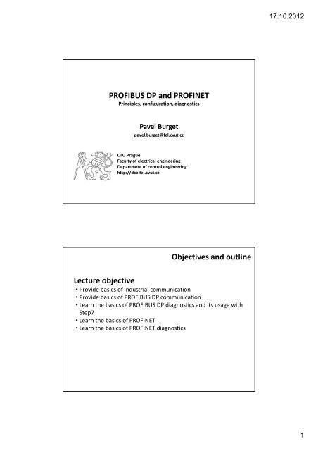
<strong>PROFIBUS</strong> <strong>DP</strong> <strong>and</strong> <strong>PROFINET</strong><br />
Principles, configuration, diagnostics<br />
Pavel Burget<br />
pavel.burget@fel.cvut.cz<br />
CTU Prague<br />
Faculty of electrical engineering<br />
Department of control engineering<br />
http://dce.fel.cvut.cz<br />
<strong>Objectives</strong> <strong>and</strong> <strong>outline</strong><br />
<strong>Lecture</strong> objective<br />
• Provide basics of industrial communication<br />
• Provide basics of <strong>PROFIBUS</strong> <strong>DP</strong> communication<br />
• Learn the basics of <strong>PROFIBUS</strong> <strong>DP</strong> diagnostics <strong>and</strong> its usage with<br />
Step7<br />
• Learn the basics of <strong>PROFINET</strong><br />
• Learn the basics of <strong>PROFINET</strong> diagnostics<br />
17.10.2012<br />
1
Supervisory level<br />
Process network<br />
Process level<br />
Field bus<br />
Field level<br />
Sensor<br />
network<br />
Operator 23<br />
4<br />
33<br />
2<br />
12<br />
2<br />
ProcessProgramovatelný network<br />
(Controller-Controller<br />
automat<br />
comm.)<br />
Direct I/Os<br />
IT net<br />
TCP IP<br />
Ethernet<br />
Control system hierarchy<br />
File<br />
Edit<br />
Fieldbus<br />
intelligent field devices<br />
<strong>PROFIBUS</strong>, <strong>PROFINET</strong>, CANopen, LON, …<br />
Senzor networks<br />
actuators, intelligent sensors.<br />
CAN, DeviceNet, SDS, ASI-bus, Interbus-S<br />
• Deterministic communication<br />
Network management<br />
Engineering tools<br />
Requirements<br />
– Limited response time (real‐time communication)<br />
– Cyclic data exchange (similar as PLC scan cycle)<br />
– Diagnostics <strong>and</strong> alarms processing<br />
– Network recovery (redundancy, station failure, …)<br />
– Adding <strong>and</strong> removing of stations –no reconfiguration<br />
needed<br />
• Ways to vertical integration<br />
– Connection to higher‐level <strong>and</strong> lower‐level networks <strong>and</strong><br />
systems<br />
17.10.2012<br />
2
• Main master –hierarchy<br />
– Master controls the traffic<br />
– Additional mechanism<br />
to add another master<br />
(redundancy, token passing, …)<br />
master<br />
Communication types<br />
(backup master<br />
or token passing)<br />
PLC PLC<br />
AP<br />
AP<br />
• Peer‐to‐peer – distributed<br />
input<br />
slaves<br />
output<br />
– PLC (master station)<br />
–<br />
can exchange data,<br />
share process<br />
variables, …<br />
Redundant masters<br />
PLC<br />
AP<br />
PLC<br />
AP<br />
More<br />
masters<br />
PLC<br />
AP<br />
– Distributed<br />
„inteligence“ – masters<br />
<strong>and</strong>/or slaves<br />
– The stations can have the same<br />
medium access rights (no master, no slaves) input<br />
slaves<br />
output<br />
A bit of history<br />
• Siemens – Sinec L2 – 80’s<br />
• st<strong>and</strong>ard DIN 19245<br />
• st<strong>and</strong>ard EN 50170 – 1996<br />
• st<strong>and</strong>ard IEC 61158 – 2003<br />
<strong>PROFIBUS</strong> <strong>DP</strong><br />
<strong>PROFIBUS</strong> International – PI<br />
• 2009 –20 years of <strong>PROFIBUS</strong>, the world most wide‐spread<br />
• Maintaining <strong>and</strong> developing specifications<br />
• Germany, USA, UK, Switzerl<strong>and</strong>, China, Japan, …<br />
• CZ – Profibus CZ, competency centre, training centre<br />
<strong>PROFIBUS</strong> & <strong>PROFINET</strong> International<br />
17.10.2012<br />
3
<strong>PROFIBUS</strong> parts<br />
Physical layer<br />
• Originally RS 485 or fibre optics, today others (RS 485‐IS, MBP)<br />
Link layer<br />
• Frame coding, medium access, error resolution (CRC, repetition)<br />
Protocol parts<br />
• <strong>PROFIBUS</strong> FMS –the oldesT, communication between PLCs<br />
• <strong>PROFIBUS</strong> <strong>DP</strong> –data exchange between PLC <strong>and</strong> remote IO,<br />
well known, functional enhancements (<strong>DP</strong>‐V1, <strong>DP</strong>‐V2)<br />
• <strong>PROFIBUS</strong> PA –process automation, explosive environment,<br />
device profiles<br />
User<br />
Layer<br />
Application<br />
(7)<br />
(3)-(6)<br />
Data Link<br />
(2)<br />
Physical<br />
(1)<br />
FMS<br />
FMS Device<br />
Profiles<br />
Fieldbus Message<br />
Specification (FMS)<br />
<strong>DP</strong><br />
not used<br />
Fieldbus Data Link (FDL)<br />
RS-485 / Fiber Optic<br />
<strong>DP</strong> Profiles<br />
<strong>DP</strong> V2<br />
<strong>DP</strong> V1<br />
<strong>DP</strong> V0<br />
<strong>PROFIBUS</strong> parts<br />
PA<br />
PA Profiles<br />
MBP Interface<br />
MBP<br />
17.10.2012<br />
4
Physical layer<br />
RS 485<br />
• Asynchronous character oriented transmission<br />
• Transmission speed 9,6 kbit/s – 12 Mbit/s<br />
• Maximum segment length 1200 m, resp. 100 m<br />
• 9 pin connectors (Canon), minimum of spurs, 32 devices at<br />
segment<br />
MBP –Manchester Bus Powered<br />
• Used by Profibus PA<br />
• Explosive environment, power from bus<br />
• Synchronous coding<br />
• Coupler power the whole<br />
segment<br />
• Device does not provide power<br />
when transmitting – passive<br />
load<br />
• Can be connected <strong>and</strong><br />
disconnected during operation<br />
Physical layer<br />
17.10.2012<br />
5
Optic fibres<br />
• High‐interference environment,<br />
big distances<br />
• Different topologies – line, ring,<br />
redundant ring<br />
Service types<br />
• SRD –Send <strong>and</strong> Request Data with reply<br />
• SDA –Send Data with Acknowledge<br />
• SDN –Send Data with No acknowledge<br />
• CSRD – Cyclic Send <strong>and</strong> Request Data with reply<br />
Physical layer<br />
Link layer<br />
17.10.2012<br />
6
token<br />
PLC<br />
PLC<br />
class token 1<br />
class token 1<br />
master<br />
master<br />
<strong>PROFIBUS</strong> communication<br />
Medium access<br />
• Active stations are in logical ring –token<br />
• Passive station answer requests –master/slave<br />
• List of active stations –LAS<br />
• TS, NS, PS, adding/removing stations<br />
• Address space exploration<br />
• Detection of new stations, presence of passive stations<br />
• Token rotation time<br />
•T TR, T RR, T TH<br />
• Logical ring initialization<br />
Engineering tool<br />
class 2 master<br />
Cyclic exchange<br />
Acyclic exchange<br />
Link layer<br />
17.10.2012<br />
7
Communication <strong>DP</strong> master (cl. 1) <strong>and</strong> slave<br />
Communication <strong>DP</strong> master (cl. 1) <strong>and</strong> slave<br />
17.10.2012<br />
8
Set_Slave_Add<br />
Slave_Diag<br />
Chk_Cfg, not ok<br />
Set_Prm, not ok<br />
Power_on<br />
WAIT_PRM<br />
WAIT_CFG<br />
DATA_EXCH<br />
<strong>DP</strong> slave state machine<br />
Slave_Diag<br />
Get_Cfg<br />
Slave_Diag<br />
Set_Prm<br />
Get_Cfg<br />
St<strong>and</strong>ard diagnostics<br />
• Parameterisation, configuration error<br />
• watchdog, sync, freeze<br />
• Ident number, master addres, extended diag available<br />
Diagnostics<br />
Extended diagnostics<br />
• device/module/channel related<br />
• May be manufacturer specific – described in GSD<br />
• Module (identifier) – st<strong>and</strong>ardadised<br />
• Channel – st<strong>and</strong>ardadised, often repeats for each module with<br />
channel error<br />
• Disconnected sensor, actuator power, etc.<br />
17.10.2012<br />
9
<strong>DP</strong> master class 1 structure<br />
<strong>DP</strong> master class 1behaviour<br />
Modes<br />
• offline<br />
• stop –FDL state machine works, master is in log. ring<br />
• clear –<strong>DP</strong> state machine works, master is in CLEAR<br />
(global_control), 0 is sent to outputs<br />
• operate – ordinary data exchange<br />
PLC modes<br />
• STOP<br />
• RUN<br />
• What is their relation to <strong>DP</strong> modes?<br />
17.10.2012<br />
10
<strong>PROFIBUS</strong> <strong>DP</strong> extended functions<br />
<strong>DP</strong>‐V0<br />
• Cyclic communication MS (<strong>DP</strong>M1), acyclic communication MS<br />
(<strong>DP</strong>M2)<br />
<strong>DP</strong>‐V1<br />
• The same as <strong>DP</strong>‐V0<br />
• Acyclic communication MS (<strong>DP</strong>M1) –alarms <strong>and</strong> acknowledge<br />
• Extended acyclic communication MS (<strong>DP</strong>M2) –device<br />
parameters<br />
<strong>DP</strong>‐V2<br />
• The same as <strong>DP</strong>‐V1<br />
• Constant cycle time (TTR), time stamps, synchronisation<br />
• Communication slave‐to‐slave – publisher/subscriber<br />
Integrated interface<br />
• HW configuration<br />
• Device (PB address)<br />
• Data modules (addresses in I <strong>and</strong> Q areas)<br />
• Communication between CPU <strong>and</strong> <strong>DP</strong> master<br />
<strong>PROFIBUS</strong> <strong>DP</strong> <strong>and</strong> Simatic S7<br />
17.10.2012<br />
11
Diagnostic information<br />
• diagnostic buffer<br />
Simatic S7 – diagnostic buffer<br />
Simatic S7 – HW configuration<br />
17.10.2012<br />
12
OB86 – rack failure<br />
• Loss of communication (station)<br />
• <strong>DP</strong> master diagnostic address<br />
• <strong>DP</strong> slave diagnostic address<br />
• <strong>DP</strong> slave Profibus address<br />
OB82 –diagnostic block<br />
• Station diagnostics<br />
• <strong>DP</strong> slave diagnostic address<br />
Simatic S7 – diagnostic address<br />
Simatic S7 – organisation blocks<br />
17.10.2012<br />
13
Diagnostic information<br />
• Set possible diagnostic events in the parameters<br />
Simatic S7 – diagnostics<br />
Simatic S7 –OB86<br />
17.10.2012<br />
14
Simatic S7 –OB86<br />
• LB11 – Profibus addres of the slave<br />
• LW8 – diagnostic addres of the slave<br />
• OB86_MDL_ADDR (LW6) – diagnostic address of the master<br />
Simatic S7 –OB82<br />
17.10.2012<br />
15
Simatic S7 –OB82<br />
• OB82_MDL_ADDR (LW6) – diagnostic addres of the slave<br />
• SFC49 –logical (diagnostic) address to physical (Profibus) address<br />
• input: LADDR, …<br />
• outputs: AREA, PB address of the slave, …<br />
• SFC71 –logical (diagnostic) address to physical (Profibus) address<br />
• input: LADDR<br />
• outputs: AREA, PB address of the slave, …<br />
Simatic S7 – reading of the <strong>DP</strong> slave diagnostics<br />
SFC 13 – diagnostic function<br />
• interface<br />
• Asynchronous execution<br />
evaluate BUSY flag<br />
More info:<br />
ET200B manual<br />
SFC 13 description<br />
GSD file<br />
17.10.2012<br />
16
Thank you for your attention.<br />
Pavel Burget<br />
pavel.burget@fel.cvut.cz<br />
CTU Prague<br />
Faculty of electrical engineering<br />
Department of control engineering<br />
http://dce.fel.cvut.cz<br />
17.10.2012<br />
17