DCC2 Specification Table of Contents
DCC2 Specification Table of Contents
DCC2 Specification Table of Contents

You also want an ePaper? Increase the reach of your titles
YUMPU automatically turns print PDFs into web optimized ePapers that Google loves.
<strong>DCC2</strong> <strong>Specification</strong><br />
This document describes the operation <strong>of</strong> the 2 nd generation CMS HCAL Data Concentrator Card<br />
(<strong>DCC2</strong>). This version is updated as <strong>of</strong> firmware version 0x3022.<br />
Last edited on October 9, 2012.<br />
<strong>Table</strong> <strong>of</strong> <strong>Contents</strong><br />
<strong>DCC2</strong> <strong>Specification</strong>...................................................................................................................................1<br />
Operational Summary................................................................................................................................2<br />
Detailed Functional Description................................................................................................................2<br />
TTCrx....................................................................................................................................................2<br />
Triggers, Event Count and Bunch Count..........................................................................................2<br />
TTC Broadcast Commands...............................................................................................................3<br />
Orbit Gap Triggers (New).....................................................................................................................4<br />
Trigger Rules.........................................................................................................................................4<br />
TTCrx Event Number FIFO..................................................................................................................5<br />
Link Receiver Blocks............................................................................................................................6<br />
Event Builder.........................................................................................................................................6<br />
Resynchronization Logic..................................................................................................................7<br />
VME Interface.......................................................................................................................................7<br />
Flash Memory........................................................................................................................................7<br />
Monitoring Counters.............................................................................................................................7<br />
Global Counters................................................................................................................................7<br />
Global Timers...................................................................................................................................8<br />
Per-Spigot Counters..........................................................................................................................9
Operational Summary<br />
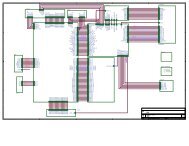
The DCC receives L1A from the TTCrx, and simultaneously receives event fragments from up to 15<br />
HTR boards. The DCC builds events by matching the event numbers from all sources, adds header and<br />
trailer information to conform to the CMS common data format (CDF). The output event stream may<br />
be error-checked and discarded, sent to an Slink transmitter and/or a VME spy buffer. Extensive errorchecking<br />
and monitoring data is collected and may be read over the VME bus or Ethernet.<br />
The DCC logic is divided into several major sections: Five link receiver blocks (3 channels each), an<br />
event builder and Slink and VME interfaces. The link receiver blocks are called LRBs (after the<br />
daughterboards on the DCC1) and the event builder FPGA is referred to as the “DSP chip” in Wu's<br />
documentation. The sections are described in more detail below.<br />
Detailed Functional Description<br />
TTCrx<br />
RJ-45<br />
HTR<br />
inputs<br />
(total 15)<br />
Xilinx<br />
XC3S200A<br />
FPGA<br />
32MByte<br />
DDR SDRAM<br />
Xilinx<br />
XC3SD1800A<br />
FPGA<br />
32MByte<br />
DDR SDRAM<br />
Illustration 1: <strong>DCC2</strong> Block Diagram<br />
Triggers, Event Count and Bunch Count<br />
Xilinx<br />
XC3S200A<br />
FPGA VME<br />
DAQ Data<br />
LVDS Tx<br />
TTCrx<br />
UMD<br />
board<br />
The primary function <strong>of</strong> the TTCRx interface[TTCRx] is to receive and process L1A triggers. In<br />
response to each L1A, the DCC captures the following three quantities and stores them in a FIFO for<br />
use by the event builder:<br />
● Event Number (EvN) is a 24-bit number which increments by 1 for each event. The EvN is set<br />
to '1' upon receipt <strong>of</strong> an Event Count Reset TTC command.<br />
Buffers<br />
Future backplane<br />
Connector board<br />
at rear <strong>of</strong> crate<br />
TP Out<br />
Readout bits in<br />
TTS<br />
TTC<br />
VME64x<br />
Buffers<br />
Out<br />
In<br />
S-Link<br />
LSC<br />
RJ-45<br />
to/from<br />
Readout<br />
Processor
● Bunch Count Number (BcN) is a 12-bit number which increments each bunch crossing clock<br />
and is reset to a programmable constant upon receipt <strong>of</strong> BC0 TTC command.<br />
● Orbit Number (OrN) is a 32-bit number which increments once each orbit when BcN=0. It is<br />
reset to a programmable constant upon receipt <strong>of</strong> a Reset Orbit Counter TTC command.<br />
Note that the TTCrx can provide the EvN and BcN, but these are ignored by the DCC.<br />
TTC Broadcast Commands<br />
The DCC must respond to the following broadcast commands received by the TTCrx.<br />
Command Brcst Meaning<br />
ResetOrbitCounter 001X1XXX Reset orbit count to zero<br />
Reset calibration laser position to 0<br />
ReSync 010X1XXX Reset the DAQ path – not enabled<br />
HardReset 011X1XXX Reset the DAQ path – not enabled<br />
Start 100X1XXX Start accepting L1As – not enabled<br />
Stop 101X1XXX Stop accepting L1As – not enabled<br />
Gap-Trigger 010X0XXX Expect calibration trigger in next gap<br />
Gap-Pedestal 011X0XXX Expect pedestal trigger in next gap<br />
Gap-Set-Laser 100X0XXX Advance laser position (see Page 4)<br />
EvtCntReset XXXXXX1X Reset EvN<br />
BC0 XXXXXXX1 Reset BcN<br />
ResetOrbitCounter: Reset orbit counter to a fixed value near zero. This should probably be a<br />
programmable constant with ~4 bits.<br />
ReSync, HardReset: Clear the DAQ path and reset all data-containing buffers in response to any <strong>of</strong><br />
these. L1A will be suspended well in advance <strong>of</strong> ReSync. VME (PCI) programmable registers should<br />
not be affected. TTS output should go to 'BUSY' when ReSync is received, and return to 'READY'<br />
when appropriate. Note: this feature is not implemented<br />
Start, Stop: Enable and Disable accepting L1A. Should be an 'or' with corresponding VME control<br />
bits for testing. Note: these features are not implemented<br />
StatReq: Indicates that the LRB status request header bit was set for this event. LRB monitoring data<br />
should be captured.<br />
Gap-Trigger: Indicates that in the gap at the end <strong>of</strong> this orbit a laser trigger will occur.<br />
Gap-Pedestal: Indicates that in the gap at the end <strong>of</strong> this orbit a pedestal trigger will occur.<br />
Gap-Set-Laser: Controls the current laser setting. Please see the section below on Page 4 below for
details <strong>of</strong> orbit gap calibration triggers.<br />
EvtCntReset (aka ECR): Reset the event number to 1. The TTCrx will reset it's internal event<br />
number to 0, so if the TTCrx event number is used, a constant 1 must be added for each event.<br />
BC0 (aka BCR): Reset BcN (BX_id) to zero after a (programmable) pipeline delay <strong>of</strong> a few clocks.<br />
When reset occurs, check that BcN = 3563. If not, generate error condition.<br />
Orbit Gap Triggers (New)<br />
HCAL calibration will be performed using two special trigger types which occur during the “gap”<br />
portion <strong>of</strong> the LHC orbit at about BX=3490. These triggers will be preceded by a Gap-Trigger TTC<br />
broadcast command for laser triggers or a Gap-Pedestal TTC command for pedestal triggers. They<br />
use the standard L1A event numbering sequence and data format, except for the addition <strong>of</strong> a new<br />
“calibration trigger type” field in the DCC header. Please see the new calibration window register<br />
described on Page Error: Reference source not found and additions to the table <strong>of</strong> TTC broadcast<br />
commands on Page 3.<br />
For L1A to be recognized as a calibration trigger, it must occur in the same orbit as a Gap-Pedestal or<br />
Gap-Trigger command, within the bunch crossing range programmed in the calibration window<br />
register.<br />
The calibration laser may be set to various configurations (details not important here). The DCC<br />
maintains a laser position register which may be read (but not written) as part <strong>of</strong> the calibration window<br />
register. It is managed as follows by TTC broadcast commands.<br />
• OCR resets the laser position to 0<br />
• A series <strong>of</strong> (n) Gap-Set-Laser commands sets the position to (n)<br />
• If a gap <strong>of</strong> > 8192 orbits (about 730ms) occurs between Gap-Set-Laser commands, the<br />
counting starts over<br />
Two event header fields are set as follows in calibration events.<br />
Event Type<br />
(TTC command)<br />
Pedestal<br />
(Gap-Pedestal)<br />
Laser<br />
(Gap-Trigger)<br />
Normal<br />
(None)<br />
Trigger Rules<br />
Evt_ty<br />
(bits 56-59 <strong>of</strong> 1 st 64b word)<br />
2 1<br />
Cal_ty<br />
(bits 56-59 <strong>of</strong> 2 nd 64b word)<br />
2 Current laser setting<br />
1 0<br />
The estimated L1A rate is 100 kHz. There are ``trigger rules'' which limit the L1A rate further. From<br />
the CMS Trigger TDR[TDR] (see section 16.4). These are provided only for reference... the DCC does<br />
not need to check for violations <strong>of</strong> these, but may assume that they are implemented as stated.<br />
i. No more than 1 L1A per 3 BX (75ns)
ii. No more than 2 L1A per 25 BX (625ns)<br />
iii.No more than 3 L1A per 100 BX (2.5μs)<br />
iv. No more than 4 L1A per 240 BX (6μs)<br />
The DCC implements a “fifth trigger rule” to protect the HTR logic against overflow as follows:<br />
No more than 30 L1A per 12000 BX (300μs)<br />
This rule is implemented using a 5 bit up-down counter which increments once pr L1A, and<br />
decrements once per 10μs. If the count reaches 30, TTS BSY is asserted until the count drops to 15.<br />
This feature may be disabled by setting a configuration register bit. A counter counts the number <strong>of</strong><br />
times this rule is invoked. NOTE: This feature is in violation <strong>of</strong> guidance from the CMS trigger group,<br />
and should not be enabled for normal running.<br />
The L1A with bunch count and event number are stored in a FIFO. An overflow <strong>of</strong> this FIFO is a fatal<br />
error and should be reported as a loss-<strong>of</strong>-sync.<br />
The TTCRx is programmed with an I2C Interface which should be controllable from the DCC logic<br />
board.<br />
TTCrx Event Number FIFO<br />
The DCC provides a circular buffer which contains information about the most recent 1k L1A received<br />
by the DCC. Each event results in a total <strong>of</strong> 16 bytes <strong>of</strong> information written, as detailed below.<br />
Offset Bits Description<br />
0 23-0 Event Number<br />
4 27-24 Current laser setting<br />
23-20 TTS state<br />
19-16 Cal_ty (calibration type) as in event header<br />
15 Gap-Trigger TTC command received<br />
14 Gap-Pedestal TTC command received<br />
13 Trigger within calibration BX window<br />
12 Valid orbit gap calibration trigger<br />
11-0 BcN<br />
8 31-0 OrN<br />
0xc Not used (all zero)<br />
The circular buffer is contained in the address range 0x4000-0x7ffc. The address <strong>of</strong> the most recent<br />
L1A received is at the address:
0x4010 + (TTCrx_fifo_read_pointer)<br />
where TTCrx_fifo_read_pointer is documented on Page Error: Reference source not found. Older L1A<br />
are found at increasing addresses (add 0x10 for each L1A). If address 0x8000 is reached, wrap address<br />
back to 0x4000. Note that since the FIFO is never explicitly cleared, one should not read more than the<br />
number <strong>of</strong> L1A indicated by the event builder block count register (documented on Page Error:<br />
Reference source not found).<br />
Link Receiver Blocks<br />
There are 3 identical input link receiver blocks (LRB), each consisting <strong>of</strong> three RJ-45 type connectors,<br />
a Spartan-3A FPGA, and a 32 Mbyte DDR SDRAM. Input data is received on each RJ-45 connector as<br />
serial LVDS data at a rate <strong>of</strong> 80MBytes/sec (40MHz * 16-bit words) on each link. The protocol is<br />
compatible with the National Semiconductor Channel Link (and in fact is transmitted by a National<br />
DS90CR285 transmitter on the HTR). One data block is expected from the HTR per L1A. Data are<br />
de-serialized by the Spartan-3AN FPGA . Headers and trailers for each event are forwarded<br />
immediately to the event builder FPGA . Event fragments are stored in their entirety in the Event FIFO<br />
(one FIFO per input spigot) implemented in the SDRAM. The HTR input data are protected with<br />
hamming codes on each word and a 16-bit CRC on each event fragment. The LRB checks these codes<br />
and keeps track <strong>of</strong> any errors seen.<br />
The low-level input protocol is given in the table below.<br />
HTR Input Function Notes<br />
0 H0 Hamming code bit 0<br />
1 H1 Hamming code bit 1<br />
2 D0 Data bit 0<br />
3 H2 Hamming code bit 2<br />
4 D1 Data bit 1<br />
5 x Not used due to PCB layout crosstalk issue (ignored<br />
by DCC). Set to '0' at HTR.<br />
6 D3 Data bit 3<br />
7 H3 Hamming code bit 3<br />
8 D4 Data bit 4<br />
9 D5 Data bit 5<br />
10 D6 Data bit 6<br />
11 D7 Data bit 7<br />
12 D8 Data bit 8<br />
13 S1 Framing bit, set to '1' for header and trailer words
HTR Input Function Notes<br />
only<br />
14 D10 Data bit 10<br />
15 H4 Hamming code bit 4<br />
16 D11 Data bit 11<br />
17 D12 Data bit 12<br />
18 D13 Data bit 13<br />
19 D14 Data bit 14<br />
20 D15 Data bit 15<br />
21 D2 Data bit 2<br />
22 D9 Data bit 9<br />
23 P Parity bit<br />
Event Builder<br />
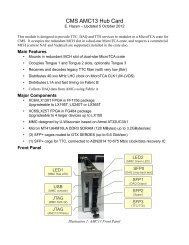
The Event Builder consists <strong>of</strong> a larger Spartan-3A FPGA with associated 32 Mbyte DDR SDRAM. A<br />
FIFO implemented internally in the FPGA stores header and trailer information for up to 256 events<br />
from each <strong>of</strong> the 15 HTR inputs. A separate L1A FIFO stores up to 1k L1A. In each FIFO the event<br />
number (EvN), bunch crossing number (BcN) and orbit number (OrN) are stored.<br />
The event builder retrieves the next entry from all enabled FIFOs, and if the EvN match the event is<br />
built according to the documented event format. If the EvN do not match, an optional procedure<br />
described below is entered in an attempt to recover synchronization.
HTR Inputs<br />
(15 total)<br />
Rx<br />
TTCrx<br />
Resynchronization Logic<br />
If the DCC and HTR event numbers either (a) match or (b) their 4 LSBs match and the 4 LSBs <strong>of</strong> the<br />
recent HTR event numbers are consecutive, the event is accepted. Otherwise, the DCC EvN is<br />
compared with that <strong>of</strong> the next HTR EvN in the FIFO. If the next HTR EvN is (a) equal or (b) smaller<br />
and the difference is less than 16 and the four LSBs <strong>of</strong> the next few HTR EvN are consecutive, the<br />
event builder will skip the current HTR event. If the next HTR EvN is larger and the difference is less<br />
than 16 and the four LSBs <strong>of</strong> the next few HTR EvN are consecutive, the DCC will insert (pad) the<br />
event with an empty block for the corresponding HTR input. In any case, as long as the errors to not<br />
persist, the DCC will eventually resynchronize the input streams. This logic may be completely<br />
disabled if desired.<br />
VME Interface<br />
The VME interface on the <strong>DCC2</strong> is implemented using a separate FPGA.<br />
Flash Memory<br />
Configuration information for the 7 FPGAs on the <strong>DCC2</strong> is held in a...<br />
Monitoring Counters<br />
The <strong>DCC2</strong> contains a large number <strong>of</strong> counters which keep track <strong>of</strong> the number <strong>of</strong> times a particular<br />
condition has occurred. These counters may be read at any time via the VME or Ethernet interfaces<br />
without affecting data taking.<br />
Global Counters<br />
Input<br />
Logic<br />
Event FIFO<br />
256 evt<br />
1K<br />
L1A FIFO<br />
256 evt<br />
Header FIFO<br />
OFW, BSY, SYN<br />
OFW, BSY, SYN<br />
Event<br />
Builder<br />
Illustration 2: <strong>DCC2</strong> Buffering<br />
The following counters record per-DCC quantities. All are 32 bits unless otherwise stated.<br />
Event builder block counter No. events processed through event builder<br />
128 evt VME<br />
FIFO SLink
S-LINK block counter events written to S-LINK transmitter card<br />
Monitored event counter events written to VME spy buffer<br />
L1A counter L1A received by TTCrx on <strong>DCC2</strong><br />
Calibration trigger counter L1A received as valid orbit gap trigger (see section xxx)<br />
CT EvN mismatch counter Obsolete?<br />
CT BcN mismatch counter Obsolete?<br />
L1 EvN mismatch counter L1A received where one or more HTR EvN do not match DCC<br />
EvN<br />
L1 BcN/OrN mismatch counter L1A received where one or more HTR BcN or OrN do not match<br />
DCC BcN or OrN<br />
Bcnt error counter BC0 received where current bunch count was not 3563<br />
Trigger rule 5 violation counter times trigger rule 5 (see Page 5) was violated<br />
S-LINK CRC error counter times an SLINK CRC was detected on output.<br />
This counter is for internal DCC debugging only.<br />
Event builder HTR CRC error<br />
counter<br />
HTR CRC errors detected in event builder chip.<br />
This is a double-check on the similar logic in the LRB<br />
Event builder word count (64 bit) 32-bit words processed by event builder<br />
S-Link word counter (64 bit) 32-bit words sent to S-Link transmitter<br />
TTCrx single errors (64 bit) Single bit errors detected by TTCrx<br />
TTCrx multi bit errors (64 bit) Multi-bit errors detected by TTCrx<br />
Global Timers<br />
The following counters measure the time the <strong>DCC2</strong> logic has been in particular states since last reset.<br />
These counters count at 64MHz based on an on-board crystal in the <strong>DCC2</strong> module (confirm this!)<br />
Run time counter Time <strong>DCC2</strong> has been in run mode<br />
READY time counter Time <strong>DCC2</strong> TTS output has been in READY state<br />
BUSY time counter Time <strong>DCC2</strong> TTS output has been in BUSY state<br />
(not able to accept L1A)<br />
Overflow warning time counter Time <strong>DCC2</strong> TTS output has been in overflow warning state
Sync lost time counter Time <strong>DCC2</strong> has been in “lost synchronization” state<br />
If this counter is non-zero data has been lost/corrupted<br />
Per-Spigot Counters<br />
LRB Counters<br />
These counters are located in the LRB logic. They typically provide accurate counts even if the event<br />
builder logic has stopped for some reason. They are 48 bits long unless otherwise noted.<br />
Word counter 32-bit Words received at LVDS input<br />
Corrected hamming code errors Words received with correctable errors (16 or 32 bit words?!)<br />
Uncorrected hamming code errors Words received with uncorrected errors (32 bit words)<br />
Truncated events Event fragments received longer than maximum (512 32-bit<br />
words) from HTR<br />
Bad ID counter Event fragments where 8 bits <strong>of</strong> EvN in header did not match<br />
trailer<br />
CRC error counter Event fragments with incorrect HTR CRC<br />
Event Builder Counters<br />
These counters are located in the Event Builder logic. They provide accurate counts for events which<br />
have cleared the Event Builder. Counters are 32 bits unless otherwise noted.<br />
EvN mismatch counter Event fragments where HTR EvN DCC EvN<br />
BcN mismatch counter Event fragments where HTR BcN DCC BcN<br />
OrN mismatch counter Event fragments where HTR OrN DCC OrN<br />
Skipped event counter Event fragments discarded by event builder to maintain<br />
synchronization (see Page 8)<br />
Padded event counter Event fragments inserted by event builder to maintain<br />
synchronization (see Page 8)<br />
Events with CERR counter Event fragments with one or more corrected HTR-DCC link<br />
errors<br />
Events with UERR counter Event fragments with one or more uncorrected HTR-DCC link<br />
errors<br />
Truncated event counter Event fragments truncated because > 512 (32-bit) words long
Short event counter Event fragments shorter than 32 bytes<br />
Events with structure error counter Event fragments where header/data/trailer sequence on HTR-DCC<br />
link is violated<br />
Odd 16bit word count Event fragments with odd 16-bit word count on HTR-DCC link<br />
HTR CRC error in event builder Event fragments with HTR CRC error detected in event builder<br />
HTR CRC error disagreement Event fragments where LRB logic and event builder disagree on<br />
CRC value (indicates internal DCC logic malfunction)<br />
Word count (64 bits) 32-bit words received by event builder input<br />
Event count (64 bits) Event fragments received by event builder input<br />
Note: The following counters monitor the HTR status bits in the 2 nd 32-bit HTR payload word.<br />
The meanings are current as <strong>of</strong> this writing, but please consult the HTR documentation for updates.<br />
Events with HTR OW flag Event fragments with HTR status bit 0 set (overflow warning)<br />
Events with HTR BZ flag Event fragments with HTR status bit 1 set (busy)<br />
Events with HTR EE flag Event fragments with HTR status bit 2 set (empty event sent)<br />
Events with HTR RL flag Event fragments with HTR status bit 3 set (rejected L1A)<br />
Events with HTR status bit4 set Event fragments with HTR status bit 4 set (bad data sent)<br />
Events with HTR LW flag Event fragments with HTR status bit 5 set (latency warning)<br />
Events with HTR OD flag Event fragments with HTR status bit 6 set (optical data error)<br />
Events with HTR CK flag Event fragments with HTR status bit 7 set (clock problem)<br />
Events with HTR BE flag Event fragments with HTR status bit 8 set (wrong orbit length)<br />
Events with HTR status bit9 set Event fragments with HTR status bit 9 set (unused)<br />
Events with HTR status bit10 set Event fragments with HTR status bit 10 set (unused)<br />
Events with HTR status bit11 set Event fragments with HTR status bit 11 set (unused)<br />
Events with HTR status bit12 set Event fragments with HTR status bit 12 set (test mode)<br />
Events with HTR CT flag Event fragments with HTR status bit 14 set (calibration trigger)<br />
Events with HTR status bit15 clr Event fragments where HTR status bit 15 is zero (error)<br />
Note: This bit is '1' as defined in the HTR data format.<br />
Events with HTR US bit set Event fragments marked as “unsuppressed” from HTR<br />
(Bit 15 in the 4 th 32bit payload word from the HTR set to '1')
Front Panel LEDs<br />
The <strong>DCC2</strong> has a number <strong>of</strong> front-panel LEDs. The meaning <strong>of</strong> each is indicated below. Note that each<br />
LED has a steady-state meeting (always on) and an error meaning (blinking). Any occurrence <strong>of</strong> the<br />
error condition will cause the LED to blink for several seconds, or if the error is recurring it will blink<br />
continuously<br />
Top Group<br />
LED<br />
Name<br />
Steady-state function Error Function<br />
VME Indicates VME activity -none-<br />
TTC Indicates TTCrx ready<br />
(TTC input signal present)<br />
L1A Blinks when L1A seen -none-<br />
Single or double bit TTC error or<br />
orbit length error<br />
DAQ SLINK enabled for output Link down active when SLINK enabled<br />
DCC DCC in run mode -none-<br />
TST Currently not used; proposed to blink to<br />
indicate power-up memory test error<br />
Middle Group (TTS)<br />
RDY TTS 'Ready' -none-<br />
BSY TTS 'Busy' output (not accepting L1A) -none-<br />
OFW TTS 'Overflow Warning' output (L1A buffer<br />
almost full)<br />
SYN TTS 'Sync Lost' output (L1A buffer<br />
overflowed or persistent EvN mis-match)<br />
HTR0 ...<br />
HTR14<br />
HTR input enabled, data present, and data<br />
valid (passes simple checks in DCC)<br />
-none-<br />
-none-<br />
HTR input enabled and:<br />
no HTR data or data fails format checks