ANNA UNIVERSITY COIMBATORE
ANNA UNIVERSITY COIMBATORE ANNA UNIVERSITY COIMBATORE
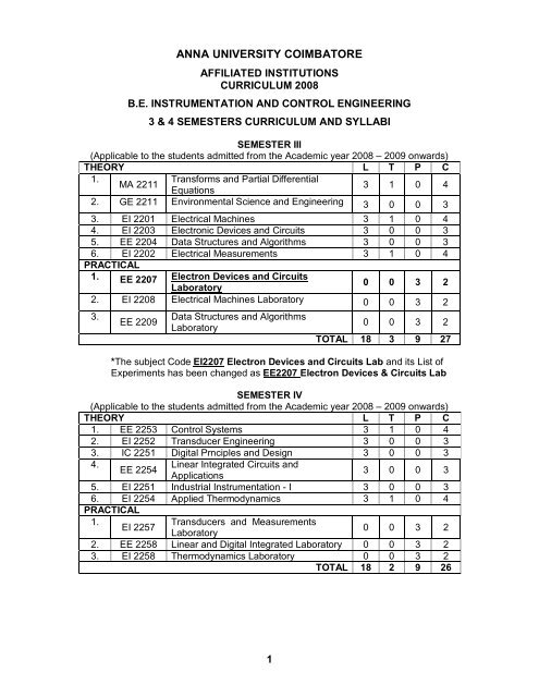
ANNA UNIVERSITY COIMBATORE AFFILIATED INSTITUTIONS CURRICULUM 2008 B.E. INSTRUMENTATION AND CONTROL ENGINEERING 3 & 4 SEMESTERS CURRICULUM AND SYLLABI SEMESTER III (Applicable to the students admitted from the Academic year 2008 – 2009 onwards) THEORY L T P C 1. MA 2211 Transforms and Partial Differential Equations 3 1 0 4 2. GE 2211 Environmental Science and Engineering 3 0 0 3 3. EI 2201 Electrical Machines 3 1 0 4 4. EI 2203 Electronic Devices and Circuits 3 0 0 3 5. EE 2204 Data Structures and Algorithms 3 0 0 3 6. EI 2202 Electrical Measurements 3 1 0 4 PRACTICAL 1. EE 2207 Electron Devices and Circuits Laboratory 0 0 3 2 2. EI 2208 Electrical Machines Laboratory 0 0 3 2 3. EE 2209 Data Structures and Algorithms Laboratory 1 0 0 3 2 TOTAL 18 3 9 27 *The subject Code EI2207 Electron Devices and Circuits Lab and its List of Experiments has been changed as EE2207 Electron Devices & Circuits Lab SEMESTER IV (Applicable to the students admitted from the Academic year 2008 – 2009 onwards) THEORY L T P C 1. EE 2253 Control Systems 3 1 0 4 2. EI 2252 Transducer Engineering 3 0 0 3 3. IC 2251 Digital Prnciples and Design 3 0 0 3 4. EE 2254 Linear Integrated Circuits and 3 0 0 3 Applications 5. EI 2251 Industrial Instrumentation - I 3 0 0 3 6. EI 2254 Applied Thermodynamics 3 1 0 4 PRACTICAL 1. EI 2257 Transducers and Measurements 0 0 3 2 Laboratory 2. EE 2258 Linear and Digital Integrated Laboratory 0 0 3 2 3. EI 2258 Thermodynamics Laboratory 0 0 3 2 TOTAL 18 2 9 26
- Page 2 and 3: MA2211 TRANSFORMS AND PARTIAL DIFFE
- Page 4 and 5: GE2211 ENVIRONMENTAL SCIENCE AND EN
- Page 6 and 7: EI2201 ELECTRICAL MACHINES 3 1 0 4
- Page 8 and 9: TEXT BOOKS 1. Millman and Halkias,
- Page 10 and 11: EI2202 ELECTRICAL MEASUREMENTS 3 1
- Page 12 and 13: EI2208 ELECTRICAL MACHINES LABORATO
- Page 14 and 15: 4. Study of the effect of Q on freq
- Page 16 and 17: 10. No load and blocked rotor test
- Page 18 and 19: EE2209 DATA STRUCTURES AND ALGORITH
- Page 20 and 21: EI2252 TRANSDUCER ENGINEERING 3 0 0
- Page 22 and 23: EE2254 LINEAR INTEGRATED CIRCUITS A
- Page 24 and 25: 5. THERMOCOUPLES AND RADIATION PYRO
- Page 26 and 27: 5. HEAT TRANSFER 9 One-dimensional
- Page 28 and 29: Detailed syllabus: 1. Loading effec
- Page 30 and 31: 3. (c) Photoelectric tachometer Aim
- Page 32 and 33: 5. Step response characteristics of
- Page 34 and 35: 7. (b) Anderson’s Bridge Aim To m
- Page 36 and 37: EE2258 LINEAR AND DIGITAL INTEGRATE
- Page 38 and 39: 5. Shift Registers: Design and impl
- Page 40 and 41: S.No. Description of Equipment Quan
- Page 42: LIST OF EQUIPMENTS S.No Apparatus Q
<strong>ANNA</strong> <strong>UNIVERSITY</strong> <strong>COIMBATORE</strong><br />
AFFILIATED INSTITUTIONS<br />
CURRICULUM 2008<br />
B.E. INSTRUMENTATION AND CONTROL ENGINEERING<br />
3 & 4 SEMESTERS CURRICULUM AND SYLLABI<br />
SEMESTER III<br />
(Applicable to the students admitted from the Academic year 2008 – 2009 onwards)<br />
THEORY L T P C<br />
1.<br />
MA 2211<br />
Transforms and Partial Differential<br />
Equations<br />
3 1 0 4<br />
2. GE 2211 Environmental Science and Engineering 3 0 0 3<br />
3. EI 2201 Electrical Machines 3 1 0 4<br />
4. EI 2203 Electronic Devices and Circuits 3 0 0 3<br />
5. EE 2204 Data Structures and Algorithms 3 0 0 3<br />
6. EI 2202 Electrical Measurements 3 1 0 4<br />
PRACTICAL<br />
1. EE 2207 Electron Devices and Circuits<br />
Laboratory<br />
0 0 3 2<br />
2. EI 2208 Electrical Machines Laboratory 0 0 3 2<br />
3.<br />
EE 2209<br />
Data Structures and Algorithms<br />
Laboratory<br />
1<br />
0 0 3 2<br />
TOTAL 18 3 9 27<br />
*The subject Code EI2207 Electron Devices and Circuits Lab and its List of<br />
Experiments has been changed as EE2207 Electron Devices & Circuits Lab<br />
SEMESTER IV<br />
(Applicable to the students admitted from the Academic year 2008 – 2009 onwards)<br />
THEORY L T P C<br />
1. EE 2253 Control Systems 3 1 0 4<br />
2. EI 2252 Transducer Engineering 3 0 0 3<br />
3. IC 2251 Digital Prnciples and Design 3 0 0 3<br />
4.<br />
EE 2254<br />
Linear Integrated Circuits and<br />
3 0 0 3<br />
Applications<br />
5. EI 2251 Industrial Instrumentation - I 3 0 0 3<br />
6. EI 2254 Applied Thermodynamics 3 1 0 4<br />
PRACTICAL<br />
1.<br />
EI 2257<br />
Transducers and Measurements<br />
0 0 3 2<br />
Laboratory<br />
2. EE 2258 Linear and Digital Integrated Laboratory 0 0 3 2<br />
3. EI 2258 Thermodynamics Laboratory 0 0 3 2<br />
TOTAL 18 2 9 26
MA2211 TRANSFORMS AND PARTIAL DIFFERENTIAL EQUATIONS 3 1 0 4<br />
(Common o all branches)<br />
OBJECTIVES<br />
The course objective is to develop the skills of the students in the areas of Transforms<br />
and Partial Differtial Equations. This will be necessary for their effective studies in a large<br />
number of engineering subjects like heat conduction, communication systems, electrooptics<br />
and electromagnetic theory. The course will also serve as a prerequisite for post<br />
graduate and specialized studies and research.<br />
1. FOURIER SERIES 9<br />
Dirichlet’s conditions – General Fourier series – Odd and even functions – Half range<br />
sine series – Half range cosine series – Complex form of Fourier Series – Parseval’s<br />
identify – Harmonic Analysis.<br />
2. FOURIER TRANSFORM 9<br />
Fourier integral theorem (without proof) – Fourier transform pair – Sine and<br />
Cosine transforms – Properties – Transforms of simple functions – Convolution theorem<br />
– Parseval’s identity.<br />
3. PARTIAL DIFFERENTIAL EQUATIONS 9<br />
Formation of partial differential equations - Lagrange’s linear equation - Solution of<br />
standard types of first order partial differential equations – Linear partial differential<br />
equations of second and higher order with constant coefficients.<br />
4. APPLICATIONS OF PARTIAL DIFFERENTIAL EQUATIONS 9<br />
Solutions of one dimensional wave equation – One dimensional equation of heat<br />
conduction – Steady state solution of two-dimensional equation of heat equation<br />
(Insulated edges excluded) – Fourier series solutions in cartesian coordinates.<br />
5. Z -TRANSFORM AND DIFFERENCE EQUATIONS 9<br />
Z-transform - Elementary properties – Inverse Z – transform – Convolution theorem -<br />
Formation of difference equations – Solution of difference equations using Z - transform.<br />
2<br />
TUTORIALS= 15<br />
Total = 60
TEXTBOOKS<br />
1. Grewal B.S, ‘Higher Engineering Mathematics’, 39 th Edition, Khanna Publishers,<br />
Delhi, 2007.<br />
REFERENCE BOOKS<br />
1. Bali.N.P. and Manish Goyal ‘A Textbook of Engineering Mathematics’, Seventh<br />
Edition, Laxmi Publications (P) Ltd.<br />
2. Ramana.B.V. ‘Higher Engineering Mathematics’ Tata Mc-GrawHill Publishing<br />
Company Limited, New Delhi.<br />
3. Glyn James ‘ ADVANCED MODERN ENGINEERING MATHEMATICS’, Third<br />
edition – Pearson education – 2007.<br />
4. ERWIN KREYSZIG ‘ ADVANCED ENGINEERING MATHEMATICS’ Eighth<br />
Edition – WILEY INDIA – 2007.<br />
3
GE2211 ENVIRONMENTAL SCIENCE AND ENGINEERING 3 0 0 3<br />
(Common to EEE, EIE, ICE, Biotech, Chemical, Fashion, Plastic, Polymer & Textile)<br />
AIM<br />
The aim of this course is to create awareness in every engineering graduate about<br />
the importance of environment, the effect of technology on the environment and<br />
ecological balance and make him/her sensitive to the environment problems in every<br />
professional endeavour that he/she participates.<br />
OBJECTIVES<br />
At the end of this course the student is expected to understand what constitutes<br />
the environment, what are precious resources in the environment, how to<br />
conserve these resources, what is the role of a human being in maintaining a<br />
clean environment and useful environment for the future generations and how to<br />
maintain ecological balance and preserve bio-diversity.<br />
<br />
INTRODUCTION TO ENVIRONMENTAL STUDIES AND NATURAL RESOURCES 9<br />
Definition, Scope and Importance – Need For Public Awareness – Forest Resources:-<br />
Use and Over - Exploitation, Deforestation, Case Studies, Timber Extraction, Mining,<br />
Dams and their Ground Water, Floods, Drought, Conflicts Over Water, Dams - Benefits<br />
and Problems – Mineral Resources:- Use Effects on Forests and Tribal People – Water<br />
Resources:- Use and Over-Utilization of Surface and Exploitation, Environmental Effects<br />
of Extracting and Using Mineral Resources, Case Studies – Food Resources: World<br />
Food Problems, Changes caused by Agriculture and Overgrazing, Effects of Modern<br />
Agriculture, Fertilizer- Pesticide Problems, Water Logging, salinity, Case Studies –<br />
Energy Resources:- Growing Energy Needs, Renewable and Non Renewable Energy<br />
Sources, Use of Alternate Energy Sources, Case Studies – Land Resources:- Land as a<br />
Resource, Land Degradation, Man Induced Landslides, Soil Erosion and Desertification<br />
– Role of an Individual in Conservation of Natural Resources – Equitable use of<br />
Resources for Sustainable Lifestyles. Field Study of Local Area to Document<br />
Environmental assets – River/Forest/Grassland/Hill/ Mountain.<br />
ECOSYSTEMS AND BIODIVERSITY 9<br />
Concepts of an Ecosystem – Structure and Function of an Ecosystem – Producers,<br />
Consumers and Decomposers – Energy Flow in the Ecosystem – Ecological Succession<br />
– Food Chains, Food Webs and Ecological Pyramids – Introduction, Types,<br />
Characteristic Features, Structure and Function of the (A) Forest Ecosystem (B)<br />
Grassland Ecosystem (C) Desert Ecosystem (D) Aquatic Ecosystems (Ponds, Streams,<br />
Lakes, Rivers, Oceans, Estuaries) – Introduction to Biodiversity – Definition: Genetic,<br />
Species and Ecosystem Diversity – Biogeographical Classification of India – Value of<br />
Biodiversity: Consumptive Use, Productive Use, Social, Ethical, Aesthetic and Option<br />
Values – Biodiversity at Global, National and Local Levels – India as a Mega-Diversity<br />
Nation – Hot-Spots of Biodiversity – Threats to Biodiversity: Habitat Loss, Poaching of<br />
Wildlife, Man-Wildlife Conflicts – endangered and Endemic Species of India –<br />
Conservation of Biodiversity: In-Situ and Ex-Situ conservation of Biodiversity.<br />
Field Study of Common Plants, Insects and Birds - Field Study of Simple Ecosystems –<br />
Pond, River, Hill Slopes, etc.<br />
4
ENVIRONMENTAL POLLUTION 9<br />
Definition – Causes, Effects and Control Measures of:- (A) Air Pollution (B) Water<br />
Pollution (C) Soil Pollution (D) Marine Pollution (E) Noise Pollution (F) Thermal Pollution<br />
(G) Nuclear Hazards – Soil Waste Management:- Causes, Effects and Control Measures<br />
of Urban and Industrial Wastes – Role of an Individual in Prevention of Pollution –<br />
Pollution Case Studies – disaster Management:- Floods, Earthquake, Cyclone and<br />
Landslides.<br />
Field Study of Local Polluted Site – Urban/Rural/Industrial/Agricultural<br />
SOCIAL ISSUES AND THE ENVIRONMENT 9<br />
From Unsustainable To Sustainable Development – Urban Problems Related To energy<br />
– Water conservation, Rain Water Harvesting, Watershed Management – Resettlement<br />
and Rehabilitation of People, Its Problems and Concerns, Case Studies – Environmental<br />
Ethics:- Issues and Possible Solutions – Climate Change, Global Warming, Acid Rain,<br />
Ozone Layer Depletion, Nuclear Accidents and Holocaust, Case Studies – Wasteland<br />
Reclamation – Consumerism and Waste Products – Environment Production Act – Air<br />
(Prevention and Control of Pollution) Act – Water (Prevention and Control of Pollution)<br />
Act – Wildlife Protection Act – Forest Conservation Act – Issues Involved in enforcement<br />
of Environmental Legislation – Public Awareness.<br />
HUMAN POPULATION AND THE ENVIRONMENT 9<br />
Population Growth, Variation Among Nations – Population Explosion – Family Welfare<br />
Programme – environment and Human Health – Human Rights – Value Education – HIV<br />
/AIDS – Women and Child Welfare – Role of Information Technology in Environment<br />
and Human Health – Case Studies.<br />
L = 45 TOTAL = 45<br />
TEXT BOOKS<br />
1. Masters, G.M., “Introduction to Environmental Engineering and Science”, Pearson<br />
Education Pvt., Ltd., 2 nd Edition, 2004.<br />
2. Miller, T.G. Jr., “Environmental Science”, Wadsworth Pub. Co.<br />
3. Townsend C., Harper, J. and Begon, M., “Essentials of Ecology”, Blackwell Science,<br />
2003.<br />
4. Trivedi, R.K., and Goel, P.K., “Introduction to Air Pollution”, Techno- Science<br />
Publications.<br />
REFERENCE BOOKS<br />
1. Erach, B., “The Biodiversity of India”, Mapin Publishing Pvt. Ltd., Ahmedabad, India.<br />
1. Trivedi, R.K., “Handbook of Environmental Law’s, Rules, Guidelines,Compliances<br />
and Standards”, Vol - I and II, Envio Media.<br />
2. Cunningham., Cooper, W.P. and Gorhani, T.H., “Environmental Encyclopedia”, Jaico<br />
Publishing House, Mumbai, 2001.<br />
4. Wages, K.D., “Environmental Management”, W.B. Saunders Co., Philadelphia, USA,<br />
1998.<br />
5
EI2201 ELECTRICAL MACHINES 3 1 0 4<br />
(Common to EIE & ICE)<br />
AIM<br />
To impart basic knowledge on Electrical machines, principles and its behavior.<br />
OBJECTIVES<br />
At the end of this course, student would have been exposed to:<br />
Theory of structures, operating principle, characteristics, and applications of D.C<br />
and A.C rotating machines and transformers in detail.<br />
Introductory knowledge on Special Machines.<br />
D.C. MACHINES 12<br />
Construction of D.C. Machines - Principle and theory of operation of D.C. generator -<br />
EMF equation - Characteristics of D.C. generators - Armature reaction – Commutation -<br />
Principle of operation of D.C. motor - Voltage equation - Torque equation - Types of D.C.<br />
motors and their characteristics –Starters - Speed control of D.C. motors - Applications.<br />
TRANSFORMERS 9<br />
Principle - Theory of ideal transformer - EMF equation - Construction details of shell and<br />
core type transformers - Tests on transformers - Equivalent circuit - Phasor diagram -<br />
Regulation and efficiency of a transformer - Introduction to three - phase transformer<br />
connections.<br />
SYNCHRONOUS MACHINES 8<br />
Principle of alternators:- Construction details, Equation of induced EMF and Vector<br />
diagram - Synchronous motor:- Starting methods, Torque, V curves, Speed control and<br />
Hunting.<br />
INDUCTION MACHINES 9<br />
Induction motor:- Construction and principle of operation, Classification of induction<br />
motor, Torque equation, Condition for maximum torque, Equivalent Circuit, Starting<br />
methods and Speed control of induction motors.<br />
SPECIAL MACHINES 7<br />
Types of single phase motor –Double revolving field theory – Cross field theory –<br />
Capacitor start capacitor run motors – Shaded pole motor – Repulsion type motor –<br />
Universal motor – Hysteresis motor - Permanent magnet synchronous motor – Switched<br />
reluctance motor – Brushless D.C motor.<br />
L = 45 TOTAL = 45<br />
TEXT BOOKS<br />
1. Nagrath, I.J., and Kothari, D.P., “ Electrical Machines”, Tata McGraw - Hill, 1997.<br />
2. Fitzgerald A.E, Kingsley C., Umans, S. and Umans S.D., “Electric Machinery”,<br />
McGraw- Hill, Singapore, 2000.<br />
REFERENCE BOOKS<br />
1. Theraja, B.L., “A Text book of Electrical Technology”, Vol.II, S.C Chand and Co.,<br />
New Delhi, 2007.<br />
2. Del Toro, V., “Electrical Engineering Fundamentals”, Prentice Hall of India, New<br />
Delhi, 1995.<br />
3. Cotton, H., “Advanced Electrical Technology”, Sir Isaac Pitman and Sons<br />
Ltd., London, 1999.<br />
6
EI2203 ELECTRONIC DEVICES AND CIRCUITS 3 0 0 3<br />
(Common to EIE & ICE)<br />
AIM<br />
OBJECTIVES<br />
To provide an exposure to various electronic devices and electronic circuits.<br />
At the end of the course, students’ will have the knowledge about functioning of<br />
various types of devices and design of various electronic circuits.<br />
SEMICONDUCTOR DIODE AND BJT 9<br />
PN Junction – Current components in a PN diode – Junction capacitance – Junction<br />
diode switching time – Zener diode – Varactor diode – Tunnel diode – Schottky diode –<br />
Transistor Structure – Basic Transistor operation – Transistor characteristics and<br />
parameters – The transistor as a switch, as an amplifier – Transistor bias circuits:-<br />
Voltage divider bias circuits, base bias circuits, emitter bias circuits, collector feedback<br />
bias circuits – DC load line – AC load line- bias stabilization, thermal runaway and<br />
thermal stability.<br />
FET, UJT and SCR 9<br />
JFET characteristics and parameters – JFET biasing, self bias, voltage divider bias – Q<br />
point, stability over temperature – MOSFET D-MOSFET, E-MOSFET – MOSFET<br />
characteristics and parameters – MOSFET biasing, zero bias, voltage divider bias<br />
method, drain feedback bias – Characteristics and applications of UJT, SCR, DIAC,<br />
TRIAC.<br />
AMPLIFIERS 9<br />
CE, CC and CB amplifiers - Small signal low frequency transistor amplifier circuits - h<br />
parameter representation of a transistor - Analysis of single stage transistor amplifier<br />
using parameters voltage gain, current gain, input impedance and output impedancefrequency<br />
response - RC coupled amplifier.<br />
Classification of Power amplifiers:- Class A, B, AB and C Power amplifiers-Push-Pull<br />
and Complementary Symmetry Push-Pull amplifiers - Design of power output, efficiency<br />
and cross-over distortion.<br />
FEEDBACK AMPLIFIERS AND OSCILLATORS 9<br />
Advantages of negative feedback - Voltage/current, series/shunt feedback-Positive<br />
feedback - Condition for oscillators - Phase shift - Wein Bridge – Hartley - Colpitts and<br />
crystal oscillators.<br />
PULSE CIRCUITS AND POWER SUPPLIES 9<br />
RC wave shaping circuits - Diode clampers and clippers – Multivibrators -Schmitt<br />
triggers - UJT - Saw tooth oscillators - Single and polyphase rectifiers and analysis of<br />
filter circuits - Design of zener and transistor series voltage regulators - Switched mode<br />
power supplies.<br />
7<br />
L = 45 TOTAL = 45
TEXT BOOKS<br />
1. Millman and Halkias, “Electronic Devices and Circuits”, Tata McGraw– Hill, 2007.<br />
2. Floyd, T.L, “Electronic Devices” 6 th Edition, Pearson Education, 2003.<br />
3. Millman and Halkias, “Integrated Electronics”, McGraw-Hill, 2004.<br />
REFERENCE BOOKS<br />
1. Mottershead, A., “Electronic Devices and Circuits an Introduction”,Prentice Hall<br />
of India, 2003.<br />
2. Boylsted and Nashelsky, “Electronic Devices and Circuit Theory”, Prentice Hall of<br />
India, 6 th Edition, 1999.<br />
3. Streetman, B. and Sanjay, B., “Solid State Electronic Devices”, Prentice- Hall<br />
of India, 5 th Edition, 2005.<br />
4. Bell, D.A., “Electronic Devices and Circuits”, Prentice Hall of India, 4 th Edition,<br />
1999.<br />
5. Millman, J., Prakash Rao., M.S. and Taub, H., “Pulse Digital and Switching<br />
Wave Forms”, McGraw-Hill, 2007.<br />
8
EE2204 DATA STRUCTURES AND ALGORITHMS 3 0 0 3<br />
(Common to EEE, EIE & ICE)<br />
AIM: To master the design and applications of linear, tree, and graph structures.<br />
To understand various algorithm design and analysis techniques.<br />
1. LINEAR STRUCTURES 9<br />
Abstract Data Types (ADT) – List ADT – array-based implementation – linked list<br />
implementation – cursor-based linked lists – doubly-linked lists – applications of lists –<br />
Stack ADT – Queue ADT – circular queue implementation – Applications of stacks and<br />
queues<br />
2. TREE STRUCTURES 9<br />
Need for non-linear structures – Tree ADT – tree traversals – left child right sibling data<br />
structures for general trees – Binary Tree ADT – expression trees – applications of trees<br />
– binary search tree ADT<br />
3. BALANCED SEARCH TREES AND INDEXING 9<br />
AVL trees – Binary Heaps – B-Tree – Hashing – Separate chaining – open addressing –<br />
Linear probing<br />
4. GRAPHS 9<br />
Definitions – Topological sort – breadth-first traversal - shortest-path algorithms –<br />
minimum spanning tree – Prim's and Kruskal's algorithms – Depth-first traversal –<br />
biconnectivity – euler circuits – applications of graphs<br />
5. ALGORITHM DESIGN AND ANALYSIS 9<br />
Greedy algorithms – Divide and conquer – Dynamic programming – backtracking –<br />
branch and bound – Randomized algorithms – algorithm analysis – asymptotic notations<br />
– recurrences – NP-complete problems<br />
L = 45 Total = 45<br />
TEXT BOOKS<br />
1. M. A. Weiss, “Data Structures and Algorithm Analysis in C”, Pearson Education Asia,<br />
2002.<br />
2. ISRD Group, “Data Structures using C”, Tata McGraw-Hill Publishing Company Ltd.,<br />
2006.<br />
REFERENCES<br />
1. A. V. Aho, J. E. Hopcroft, and J. D. Ullman, “Data Structures and Algorithms”,<br />
Pearson Education, 1983.<br />
2. R. F. Gilberg, B. A. Forouzan, “Data Structures: A Pseudocode approach with C”,<br />
Second Edition, Thomson India Edition, 2005.<br />
3. Sara Baase and A. Van Gelder, “Computer Algorithms”, Third Edition, Pearson<br />
Education, 2000.<br />
4. T. H. Cormen, C. E. Leiserson, R. L. Rivest, and C. Stein, "Introduction to<br />
algorithms", Second Edition, Prentice Hall of India Ltd, 2001.<br />
9
EI2202 ELECTRICAL MEASUREMENTS 3 1 0 4<br />
(Common to EIE & ICE)<br />
AIM<br />
To provide adequate knowledge in electrical measurements and instrumentation.<br />
OBJECTIVES<br />
To make the students to gain a clear knowledge of the basic laws governing the<br />
operation of electrical instruments and the measurement techniques.<br />
i. Emphasis is laid on the meters used to measure current & voltage.<br />
ii. To have an adequate knowledge in the measurement techniques for<br />
power and energy, power and energy meters are included.<br />
iii. Elaborate discussion about potentiometer & instrument transformers.<br />
iv. Detailed study of resistance measuring methods.<br />
v. Detailed study of inductance and capacitance measurement.<br />
1. MEASUREMENT OF VOLTAGE AND CURRENT 9<br />
Galvanometers – Ballistic, D’Arsonval galvanometer – Theory, calibration, application –<br />
Principle, construction, operation and comparison of moving coil, moving iron meters,<br />
dynamometer, induction type & thermal type meter, rectifier type – Extension of range<br />
and calibration of voltmeter and ammeter – Errors and compensation.<br />
2. MEASUREMENT OF POWER AND ENERGY 9<br />
Electrodynamometer type wattmeter – Theory & its errors – Methods of correction – LPF<br />
wattmeter – Phantom loading – Induction type kWh meter – Induction type energy meter<br />
– Calibration of wattmeter.<br />
3. POTENTIOMETERS & INSTRUMENT TRANSFORMERS 9<br />
DC potentiometer – Basic circuit, standardization – Laboratory type (Crompton’s) – AC<br />
potentiometer – Drysdale (polar type) type – Gall-Tinsley (coordinate) type – Limitations<br />
& applications – C.T and P.T construction, theory, operation and characteristics.<br />
4. RESISTANCE MEASUREMENT 9<br />
Measurement of low, medium & high resistance – Ammeter, voltmeter method –<br />
Wheatstone bridge – Kelvin double bridge – Series and shunt type ohmmeter – High<br />
resistance measurement – Megger – Direct deflection methods – Price’s guard-wire<br />
method – Earth resistance measurement.<br />
5. IMPEDANCE MEASUREMENT 9<br />
A.C bridges – Measurement of inductance, capacitance – Q of coil – Maxwell Bridge –<br />
Wein’s bridge – Schering bridge – Anderson bridge – Campbell bridge to measure<br />
mutual inductance – Errors in A.C. bridge methods and their compensation – Detectors<br />
– Excited field – A.C. galvanometer – Vibration galvanometer<br />
L = 45 T = 15 Total = 60<br />
TEXT BOOKS<br />
1. E.W. Golding & F.C.Widdis, ‘Electrical Measurements & Measuring Instruments’,<br />
A.H.Wheeler & Co, 2001<br />
2. A.K. Sawhney, ‘Electrical & Electronic Measurements and Instrumentation’,<br />
Dhanpath Rai & Co (P) Ltd, 2004.<br />
REFERENCE BOOKS<br />
1. J.B.Gupta, ‘A Course in Electronic and Electrical Measurements and<br />
Instrumentation’, S.K. Kataria & Sons, Delhi, 2003.<br />
2. S.K.Singh, ‘Industrial Instrumentation and control’, Tata McGraw Hill, 2 nd<br />
edn.,2002.<br />
3. H.S.Kalsi, ‘Electronic Instrumentation’, Tata McGraw Hill, 2004.<br />
4. Martin U. Reissland, ‘Electrical Measurement – Fundamental Concepts and<br />
Applications’, New Age International (P) Ltd., 2001.<br />
10
III SEMESTER<br />
EE2207 ELECTRON DEVICES AND CIRCUITS LABORATORY 0 0 3 2<br />
(REVISED)<br />
1. Characteristics of Semiconductor diode and Zener diode<br />
2. Characteristics of Transistor under common emitter, common collector and<br />
common base configurations<br />
3. Characteristic of FET<br />
4. Characteristic of UJT<br />
5. Characteristics of SCR, DIAC and TRIAC<br />
6. Photo diode, phototransistor characteristics and study of light activated relay<br />
circuit.<br />
7. Static characteristics of Thermistors<br />
8. Single phase half wave and full wave rectifiers with inductive and capacitive<br />
filters.<br />
9. Differential amplifiers using FET<br />
10. Study of CRO<br />
11. Series and Parallel resonance circuits<br />
12. Realization of Passive filters.<br />
P : 45 TOTAL : 45<br />
REQUIREMENT FOR A BATCH OF 30 STUDENTS<br />
S.No. Description of Equipment Quantity<br />
required<br />
1. Regulated Power Supply 15<br />
2. Dual Tree CRO (20 MHz) 15<br />
3. Function Generator 15<br />
4. 3 1/2 Digit digital multimeter 10<br />
5. Bread Boards 40<br />
6. Transistor 25 Nos.<br />
7. JFET 10 Nos.<br />
8. Diode 10 Nos.<br />
9. Zener Diode 5 Nos.<br />
10. UJT 5 Nos.<br />
11. Photo Diode 5 Nos.<br />
12. Photo Transistor 5 Nos.<br />
13. Thermistors 5 Nos.<br />
14. OP-amp 10 Nos.<br />
15. Milli Ammeter (0-100mA) 15 Nos.<br />
16. Micro Ammeter (0-50µA) 10 Nos.<br />
17. Low range voltmeter (0-30V) 10 Nos.<br />
18. Resistor of various ranges 50 Nos.<br />
19. Capacitors of various ranges 50 Nos.<br />
20. Connecting wires<br />
11<br />
Sufficient<br />
Nos<br />
Quantity<br />
available<br />
Deficiency<br />
%
EI2208 ELECTRICAL MACHINES LABORATORY 0 0 3 2<br />
(Common to EIE & ICE)<br />
OBJECTIVE<br />
To impart hands on experience in verification of circuit laws and theorems,<br />
measurement f circuit parameters, study of circuit characteristics and simulation<br />
of time response.<br />
To expose the students to the basic operation of electrical machines and help<br />
them to develop experimental skills.<br />
Verification of Kirchoff’s voltage and current laws, Thevenin’s and Norton’s<br />
Theorems.<br />
Measurement of time constant of series R-C electric circuits and frequency<br />
response of a series RLC circuit.<br />
Study of the effect of Q on frequency response and bandwidth of series and<br />
parallel resonant circuits<br />
Open circuit and load characteristics of self-excited D.C. generator.<br />
Load test on D.C. shunt motor.<br />
Load test on D.C. series motor.<br />
Swinburne’s test and speed control of D.C. shunt motor.<br />
Load test on single phase transformer and open circuit and short circuit test on<br />
single phase transformer<br />
Load test on single phase induction motor.<br />
No load and blocked rotor tests on three phase induction motor (Determination of<br />
equivalent circuit parameters)<br />
P = 45 Total = 45<br />
12
Detailed Syllabus<br />
1. Verification of Kirchoff’s voltage and current laws, Thevenin’s and Norton’s<br />
Theorems<br />
Aim<br />
To verify Kirchchoff’s voltage and current laws, Thevenin’s and Norton’s<br />
Theorems.<br />
Exercises<br />
a) Verify the Kirchoff’s voltage and current law in a series circuit and in a circuit<br />
with series and parallel combination.<br />
b) Determine the Thevenins equivalent voltage VTH and resistance RTH of a DC<br />
circuit with a single voltage source.<br />
(i) Verify experimentally the values of VTH and RTH in solving a series –<br />
parallel circuit.<br />
(ii) Determine the values of Norton’s constant – current source IN and Norton’s<br />
current - source resistance RN in a DC circuit containing one or two<br />
voltage sources.<br />
2. Measurement of time constant of series R-C electric circuits and frequency<br />
response of a series RLC circuit.<br />
(a) Measurement of time constant of series R-C electric circuits<br />
Aim<br />
To determine experimentally the time taken by a capacitor to charge and<br />
discharge through a resistance.<br />
Exercises<br />
a. Determine experimentally the time taken by a capacitor to charge through a<br />
resistor and obtain a plot between voltage across capacitor and time.<br />
b. Determine experimentally the time taken by a capacitor to discharge through<br />
a resistor and obtain a plot between voltage across capacitor and time.<br />
3. (b) Resonant frequency and frequency response of a series R L C circuit.<br />
Aim<br />
To determine experimentally the resonant frequency fR of a series RLC circuit.<br />
To verify the resonant frequency of a series RLC circuit is given by the formula<br />
fR = 1 / 2π√ LC.<br />
To develop experimentally the frequency – response curve of a series RLC<br />
circuit<br />
Exercises<br />
Draw the frequency response curve of a series RLC circuit (VL Vs f, VC Vs f)<br />
Experimentally show the following<br />
Resonant frequency fr = 1 / 2π √LC<br />
The impedance at resonance Z = R<br />
13
4. Study of the effect of Q on frequency response and bandwidth of series<br />
and parallel resonant circuits<br />
Aim<br />
To study the effect of Q on frequency response and on bandwidth at the half –<br />
power points of series and parallel resonant circuits.<br />
Exercises<br />
Experimentally study the effect of Q on frequency response and bandwidth<br />
of RLC resonant circuit and obtain the following for three values of<br />
Q.<br />
I Vs frequency<br />
Half power points<br />
Bandwidth<br />
Ve Vs f<br />
VL Vs f<br />
Experimentally determine the resonant frequency in a parallel resonant circuit.<br />
Draw current versus frequency in parallel resonant circuit.<br />
5. Open circuit and load characteristics of self excited DC Generator<br />
Aim<br />
To conduct no load and load test on self excited generator and obtain the<br />
characteristics.<br />
Exercise<br />
Obtain the open circuit characteristics of a self excited D.C generator and<br />
determine critical resistance.<br />
Draw the external and internal characteristics of a self excited D.C generator and<br />
compute full load regulation.<br />
Load Test on DC Shunt motor.<br />
Aim<br />
To conduct load test on DC shunt motor and draw the characteristic curves.<br />
Exercise<br />
1. Draw the following characteristic curves for DC shunt motor<br />
Output Vs η%<br />
Output Vs Torque<br />
Output Vs N<br />
Output Vs IL<br />
Torque Vs N<br />
14
6. Load Test on DC series motor<br />
Aim<br />
To conduct load test on DC series motor and to obtain the characteristics.<br />
Exercise<br />
1. Draw the following characteristics curve for DC series motor<br />
Output Vs η%<br />
Output Vs T<br />
Output Vs N<br />
Output Vs I<br />
Torque Vs N<br />
7. Swinburne’s Test and speed control of DC shunt motor<br />
Aim<br />
To conduct Swinburne’s test and predetermine the performance characteristics<br />
of DC machine and speed control of DC motor.<br />
Exercise<br />
Predetermine efficiency at various load current while operating as a motor and<br />
generator and plot a graph for O/P Vs η% output Vs η%<br />
Draw the following curves for<br />
If Vs N at Va = 0.8 Va and Va<br />
Va Vs N at 0.8 If and If<br />
8. Load Test On Single-Phase Transformer and Open Circuit And Short<br />
Circuit Tests On Single Phase Transformer<br />
Aim<br />
To conduct load test on the given single phase transformer and determine its<br />
performance<br />
2. To conduct O.C and S.C test on a single phase transformer and calculate its<br />
performance<br />
Exercise<br />
a. Draw the following graph for single phase transformer<br />
Output Vs η%<br />
b. Determine the equivalent circuit of the transformer.<br />
c. Predetermine the efficiency at different load at UPF and 0.8 Power factor<br />
lagging.<br />
d. Predetermine the full load regulation at different power factor.<br />
e. Draw the following curves<br />
(i). Output Vs η%<br />
(ii). Power factor Vs %Regulation<br />
9. Load test on single phase induction motor<br />
Aim<br />
To obtain the load characteristics of single phase motor by load test.<br />
Exercise<br />
a. Conduct the load test on given single-phase induction motor and draw the<br />
following curves.<br />
1. Output Vs % η<br />
2. Output Vs Speed<br />
3. Output Vs Line current IB<br />
4. Output Vs Slip<br />
5. Output Vs Power factor<br />
15
10. No load and blocked rotor test on three-phase induction motor<br />
Aim<br />
To conduct no load and blocked rotor test and to draw the equivalent circuit and<br />
predetermine its performance.<br />
Exercise<br />
a. Determine the equivalent circuit parameters.<br />
b. Draw the circle diagram and predetermine the efficiency, torque, power<br />
factor, slip and line current for three load condition.<br />
Predetermine the performance characteristics using the equivalent circuit for<br />
three load condition.<br />
REQUIREMENT FOR A BATCH OF 30 STUDENTS<br />
S.No. Description of Equipment<br />
1.<br />
D.C motor – Generator set<br />
D.C motor – Shunt Generator<br />
D.C motor – Compound Generator<br />
16<br />
Quantity<br />
required<br />
2 set<br />
2 set<br />
2. D.C. Shunt Motor 2 Nos.<br />
3. D.C. Series Motor 1 No.<br />
4. D.C. Compound Motor 1 No.<br />
5. Single phase transformers 7 Nos.<br />
6. Three phase transformers 2 Nos.<br />
7. D.C. Motor – Alternator set 4 sets<br />
8.<br />
Three phase Induction Motor (Squirrel<br />
cage)<br />
3 Nos.<br />
9. Three phase slip ring Induction Motor 1 No.<br />
10. Single phase Induction Motor 2 Nos.<br />
11.<br />
Resistive load<br />
3 phase – 2 , single phase - 3<br />
5 Nos.<br />
12. Inductive load 1 No.<br />
13. Single phase Auto transformer 5 Nos.<br />
14. Three phase Auto transformer 3 Nos.<br />
15.<br />
16.<br />
Moving Coil Ammeter of different<br />
ranges<br />
Moving Coil Voltmeter of different<br />
ranges<br />
20 Nos.<br />
20 Nos.<br />
Quantity<br />
available<br />
Deficiency<br />
%
S.No. Description of Equipment<br />
17.<br />
18.<br />
19.<br />
Moving Iron Ammeter of different<br />
ranges<br />
Moving Iron voltmeter of different<br />
ranges<br />
Wire wound Rheostats of different<br />
ratings<br />
17<br />
Quantity<br />
required<br />
20 Nos.<br />
20 Nos.<br />
30 Nos.<br />
20. Tachometers 10 Nos.<br />
21.<br />
22.<br />
Single element wattmeters of different<br />
ranges<br />
UPF / LPF<br />
Double element wattmeters of different<br />
ranges<br />
20 Nos.<br />
4 Nos.<br />
23. Power factor meter 2 Nos.<br />
24. Digital multimeter 5 Nos.<br />
25.<br />
26.<br />
Three point starter, four point<br />
starter,DOL starter, manual star / delta<br />
starter, semi automatic and fully<br />
automatic star / delta starter<br />
SCR based semi and fully controlled<br />
rectifier module<br />
1 No each<br />
for study<br />
experiment<br />
2 Nos.<br />
27. SCR based chopper module 2 Nos.<br />
28. SCR based inverter module 2 Nos.<br />
29.<br />
SCR based AC voltage regulation<br />
module<br />
30. SCR, MOSFET, IGBT Trainer module<br />
2 Nos.<br />
Each 2<br />
Nos.<br />
Quantity<br />
available<br />
Deficiency<br />
%
EE2209 DATA STRUCTURES AND ALGORITHMS LAB 0 0 3 2<br />
(Common to EEE, EIE & ICE)<br />
Aim: To develop skills in design and implementation of data structures and their<br />
applications.<br />
1. Implement singly and doubly linked lists.<br />
2. Represent a polynomial as a linked list and write functions for polynomial<br />
addition.<br />
3. Implement stack and use it to convert infix to postfix expression<br />
4. Implement array-based circular queue and use it to simulate a producerconsumer<br />
problem.<br />
5. Implement an expression tree. Produce its pre-order, in-order, and post-order<br />
traversals.<br />
6. Implement binary search tree.<br />
7. Implement insertion in AVL trees.<br />
8. Implement priority queue using heaps<br />
9. Implement hashing techniques<br />
10. Perform topological sort on a directed graph to decide if it is acyclic.<br />
11. Implement Dijkstra's algorithm using priority queues<br />
12. Implement Prim's and Kruskal's algorithms<br />
13. Implement a backtracking algorithm for Knapsack problem<br />
14. Implement a branch and bound algorithm for traveling salesperson problem<br />
15. Implement any randomized algorithm.<br />
REQUIREMENT FOR A BATCH OF 30 STUDENTS<br />
S.No. Description of Equipment Quantity<br />
required<br />
1. Computer(Pentium 4) 40 Nos with one<br />
server<br />
2. Dot matrix printer 3 Nos<br />
3. Laser Printer 2 Nos<br />
4. UPS (5 KVA) 2<br />
5. Turbo C 40 Nodes<br />
18<br />
P = 45 Total = 45<br />
Quantity<br />
available<br />
Deficiency<br />
%
EE2253 CONTROL SYSTEMS 3 1 0 4<br />
(Common to EEE, EIE & ICE)<br />
AIM<br />
To provide sound knowledge in the basic concepts of linear control theory and<br />
design of control system.<br />
OBJECTIVES<br />
i To understand the methods of representation of systems and to desire<br />
their transfer function models.<br />
ii To provide adequate knowledge in the time response of systems and<br />
steady state error analysis.<br />
iii To accord basic knowledge in obtaining the open loop and closed–loop<br />
frequency responses of systems.<br />
iv To understand the concept of stability of control system and methods of<br />
stability analysis.<br />
v To study the three ways of designing compensation for a control system.<br />
1. SYSTEMS AND THEIR REPRESENTATION 9<br />
Basic elements in control systems – Open and closed loop systems – Electrical analogy<br />
of mechanical and thermal systems – Transfer function – Synchros – AC and DC<br />
servomotors – Block diagram reduction techniques – Signal flow graphs.<br />
2. TIME RESPONSE 9<br />
Time response – Time domain specifications – Types of test input – I and II order system<br />
response – Error coefficients – Generalized error series – Steady state error – P, PI, PID<br />
modes of feed back control.<br />
3. FREQUENCY RESPONSE 9<br />
Frequency response – Bode plot – Polar plot – Determination of closed loop response<br />
from open loop response – Correlation between frequency domain and time domain<br />
specifications.<br />
4. STABILITY OF CONTROL SYSTEM 9<br />
Characteristics equation – Location of roots in S plane for stability – Routh Hurwitz<br />
criterion – Root locus construction – Effect of pole, zero addition – Gain margin and<br />
phase margin – Nyquist stability criterion.<br />
5. COMPENSATOR DESIGN 9<br />
Performance criteria – Lag, lead and lag-lead networks – Compensator design using<br />
bode plots.<br />
L = 45 T = 15 Total = 60<br />
TEXT BOOKS<br />
1. I.J. Nagrath and M. Gopal, ‘Control Systems Engineering’, New Age International<br />
Publishers, 2003.<br />
2. Benjamin C. Kuo, Automatic Control systems, Pearson Education, New Delhi, 2003.<br />
REFERENCE BOOKS<br />
1. K. Ogata, ‘Modern Control Engineering’, 4 th edition, PHI, New Delhi, 2002.<br />
2. Norman S. Nise, Control Systems Engineering, 4 th Edition, John Wiley, New Delhi,<br />
2007.<br />
3. Samarajit Ghosh, Control systems, Pearson Education, New Delhi, 2004<br />
4. M. Gopal, ‘Control Systems, Principles and Design’, Tata McGraw Hill, New Delhi,<br />
2002.<br />
19
EI2252 TRANSDUCER ENGINEERING 3 0 0 3<br />
(Common to EIE & ICE)<br />
AIM<br />
To provide adequate knowledge in sensors and transducers.<br />
OBJECTIVES<br />
i. To impart knowledge about the principles and analysis of sensors.<br />
ii. Discussion of errors and error analysis.<br />
iii. Emphasis on characteristics and response of transducers.<br />
iv. To have an adequate knowledge in resistance transducers.<br />
v. Basic knowledge in inductance and capacitance transducers and<br />
exposure to other transducers.<br />
1. SCIENCE OF MEASUREMENTS AND INSTRUMENTATION OF<br />
TRANSDUCERS 9<br />
Units and standards – Calibration methods – Static calibration – Classification of errors –<br />
Error analysis – Statistical methods – Odds and uncertainty – Classification of<br />
transducers – Selection of transducers.<br />
2. CHARACTERISTICS OF TRANSDUCERS 9<br />
Static characteristics – Accuracy, precision, resolution, sensitivity, linearity -Dynamic<br />
characteristics – Mathematical model of transducer – Zero, I and II order transducers.<br />
Response to impulse, step, ramp and sinusoidal inputs.<br />
3. VARIABLE RESISTANCE TRANSDUCERS 9<br />
Principle of operation, construction details, characteristics and application of<br />
potentiometer, strain gauge, resistance thermometer, Thermistor, hot-wire anemometer,<br />
piezoresistive sensor and humidity sensor.<br />
4. VARIABLE INDUCTANCE AND VARIABLE CAPACITANCE<br />
RANSDUCERS 9<br />
Induction potentiometer – Variable reluctance transducers – EI pick up – Principle of<br />
operation, construction details, characteristics and application of LVDT –Capacitive<br />
transducer and types – Capacitor microphone – Frequency response.<br />
5. OTHER TRANSDUCERS 9<br />
Piezoelectric transducer, Hall Effect transducer – Different types of Photo detectors-<br />
Digital transducers – Smart sensors - Fibre optic sensors, SQUID sensors, Film sensors,<br />
MEMS – Nano sensors.<br />
L = 45 Total = 45<br />
TEXT BOOKS<br />
1. E.A. Doebelin, ‘Measurement Systems – Applications and Design’, Tata McGraw<br />
Hill, New York, 2000.<br />
2. A.K. Sawhney, ‘A course in Electrical & Electronic Measurement and<br />
Instrumentation’, Dhanpat Rai and Co (P) Ltd., 2004.<br />
REFERENCE BOOKS<br />
1. D. Patranabis, ‘Sensors and Transducers’, Prentice Hall of India, 1999.<br />
2. John P. Bentley, ‘Principles of Measurement Systems’, III Edition, Pearson<br />
Education, 2000.<br />
20
IC2251 DIGITAL PRINCIPLES AND DESIGN 3 0 0 3<br />
AIM<br />
To introduce the fundamentals of Digital Circuits, combinational and sequential circuit, digital<br />
system design and VSI circuits.<br />
OBJECTIVES<br />
i. To review Boolean algebra and to simplify the mathematical expressions<br />
using Boolean functions – simple problems.<br />
ii. To study implementation of combinational circuits<br />
iii. To study the design of various synchronous and asynchronous circuits.<br />
iv. To expose the students to programmable logic devices and digital logic<br />
families.<br />
V To introduce the concepts of VLSI circuits<br />
1. DESIGN OF COMBINATIONAL CIRCUITS 9<br />
Review of Boolean algebra – codes, simplification using K-maps & Quine McCluskey<br />
method. Design of adder, subtractor, comparators, code converters, encoders,<br />
decoders, multiplexers and demultiplexers. Function realization using gates and<br />
multiplexers.<br />
2. SYNCHRONOUS AND ASYNCHRONOUS SEQUENTIAL CIRCUITS 9<br />
Flip flops - SR, D, JK and T. Analysis of synchronous sequential circuits; design of<br />
synchronous sequential circuits – Completely and incompletely specified sequential<br />
circuits - state diagram; state reduction; state assignment, Counters – synchronous, a<br />
synchronous, updown and Johnson counters; shift registers.<br />
Analysis of asynchronous sequential machines, state assignment, asynchronous<br />
Design problem.<br />
3. PROGRAMMABLE LOGIC DEVICES 9<br />
Programmable logic Arrays, Programmable array logic, Realizing logic function using<br />
Multiplexers, Decoders, ROM, PLA, PAL. Design of sequential Networks using PAL,<br />
PLA – Programmable Gate arrays – FPGA – CPLD.<br />
4. DIGITAL LOGIC FAMILIES 9<br />
TTL, CMOS, NMOS, Dynamic MOS , ECL, I 2 L, Operating conditions, Parameters,<br />
Interpreting data sheets. Power supply grounding considerations for digital ICs, TTL – to<br />
– CMOS Interface, CMOS – to – TTL interface.<br />
5. INTRODUCTION TO VLSI 9<br />
Fundamental consideration – NMOS, CMOS, Design of combinational logic gates in<br />
CMOS.<br />
L = 45 Total =45<br />
TEXT BOOKS<br />
1. M. Morris Mano, ‘Digital Logic and Computer Design’, Prentice Hall of India,<br />
2002.<br />
2. S.M.Sze, ‘VLSI Technology’, 2 nd Edition, Tata McGraw Hill Publising Co. New<br />
Delhi, 1996.<br />
3. Charles H.Roth, ‘Fundamentals Logic Design’, Jaico Publishing, IV edition, 2002.<br />
REFERENCES<br />
1. Theodore. F. Bogart,’ Introduction to Digital Circuits’, McGraw – Hill International<br />
edition.<br />
2. John M.Yarbrough, ‘Digital Logic, Application & Design’, Thomson, 2002.<br />
3. John F.Wakerly, ‘Digital Design Principles and Practice’, 3 rd edition, Pearson<br />
Education, 2002.<br />
21
EE2254 LINEAR INTEGRATED CIRCUITS AND APPLICATIONS 3 0 0 3<br />
(Common to EEE, EIE & ICE)<br />
AIM<br />
To introduce the concepts for realizing functional building blocks in ICs,<br />
fabrications & application of ICs.<br />
OBJECTIVES<br />
i. To study the IC fabrication procedure.<br />
ii. To study characteristics; realize circuits; design for signal analysis using<br />
Op-amp ICs.<br />
iii. To study the applications of Op-amp.<br />
iv. To study internal functional blocks and the applications of special ICs like<br />
Timers, PLL circuits, regulator Circuits, ADCs.<br />
1. IC FABRICATION 9<br />
IC classification, fundamental of monolithic IC technology, epitaxial growth, masking and<br />
etching, diffusion of impurities. Realisation of monolithic ICs and packaging. Fabrication<br />
of diodes, capacitance, resistance and FETs.<br />
2. CHARACTERISTICS OF OPAMP 9<br />
Ideal OP-AMP characteristics, DC characteristics, AC characteristics, offset voltage and<br />
current: voltage series feedback and shunt feedback amplifiers, differential amplifier;<br />
frequency response of OP-AMP; Basic applications of op-amp – summer, differentiator<br />
and integrator.<br />
3. APPLICATIONS OF OPAMP 9<br />
Instrumentation amplifier, first and second order active filters, V/I & I/V converters,<br />
comparators, multivibrators, waveform generators, clippers, clampers, peak detector,<br />
S/H circuit, D/A converter (R-2R ladder and weighted resistor types), A/D converter -<br />
Dual slope, successive approximation and flash types.<br />
4. SPECIAL ICs 9<br />
555 Timer circuit – Functional block, characteristics & applications; 566-voltage<br />
controlled oscillator circuit; 565-phase lock loop circuit functioning and applications,<br />
Analog multiplier ICs.<br />
5. APPLICATION ICs 9<br />
IC voltage regulators - LM317, 723 regulators, switching regulator, MA 7840, LM 380<br />
power amplifier, ICL 8038 function generator IC, isolation amplifiers, opto coupler, opto<br />
electronic ICs.<br />
L = 45 Total = 45<br />
TEXT BOOKS<br />
1. Ramakant A.Gayakward, ‘Op-amps and Linear Integrated Circuits’, IV edition,<br />
Pearson Education, 2003 / PHI. (2000)<br />
2. D.Roy Choudhary, Sheil B.Jani, ‘Linear Integrated Circuits’, II edition, New Age,<br />
2003.<br />
REFERENCE BOOKS<br />
1. Jacob Millman, Christos C.Halkias, ‘Integrated Electronics - Analog and Digital<br />
circuits system’, Tata McGraw Hill, 2003.<br />
2. Robert F.Coughlin, Fredrick F.Driscoll, ‘Op-amp and Linear ICs’, Pearson<br />
Education, 4 th edition, 2002 / PHI.<br />
3. David A.Bell, ‘Op-amp & Linear ICs’, Prentice Hall of India, 2 nd edition, 1997<br />
22
EI2251 INDUSTRIAL INSTRUMENTATION – I 3 0 0 3<br />
(Common to EIE & ICE)<br />
AIM<br />
To equip the students with relevant knowledge to suit the industrial requirements.<br />
OBJECTIVES<br />
To provide sound knowledge about various techniques used for the<br />
measurement<br />
of industrial parameters.<br />
i. Discussion of load cells, torque meter and various velocity pick-ups.<br />
ii. Exposure to various accelerometer pick-ups, vibrometers, density and<br />
viscosity pick-ups.<br />
iii. To have an adequate knowledge about pressure transducers.<br />
iv. To have an idea about the temperature standards, calibration and signal<br />
conditioning used in RTD’s.<br />
v. To have a sound knowledge about thermocouples and pyrometry<br />
techniques.<br />
1. MEASUREMENT OF FORCE, TORQUE AND VELOCITY 9<br />
Electric balance – Different types of load cells – Hydraulic, pneumatic strain gauge-<br />
Magneto elastic and Piezo electric load cell – Different methods of torque<br />
measurements: strain gauge-Relative angular twist-Speed measurement:-Capacitive<br />
tacho-Dragcup type tacho-D.C and A.C tachogenerators – Stroboscope.<br />
2. MEASUREMENT OF ACCELERATION, VIBRATION AND DENSITY 9<br />
Accelerometers:- LVDT, Piezo-electric, Strain gauge and Variable reluctance type<br />
accelerometer – Mechanical type vibration instruments – Seismic instruments as an<br />
accelerometer – Vibrometers : Calibration of vibration pickups – Units of density and<br />
specific gravity – Baume scale, and API scale- Pressure head type densitometers- Float<br />
type densitometers – Ultrasonic densitometer- Bridge type gas densitometer.<br />
3. PRESSURE MEASUREMENT 9<br />
Units of pressure-Manometers-Different types –Elastic type pressure gauges: Bourdon<br />
tube, bellows and diaphragms-Electrical methods: Elastic elements with LVDT and strain<br />
gauges –Capacitive type pressure gauge –Piezo-resistive pressure sensor-Resonator<br />
pressure sensor-Measurement of vacuum:-McLeod gauge-Thermal conductivity gauges-<br />
Ionization gauges:– Cold cathode type and hot cathode type-Testing and calibration of<br />
pressure gauges-Dead weight tester.<br />
4. TEMPERATURE MEASUREMENT 9<br />
Definitions and standards-Primary and secondary fixed points –Calibration of<br />
thermometers - Different types of filled in system thermometer-Sources of errors in filled<br />
in systems and their compensation-Bimetallic thermometers – Electrical methods of<br />
temperature measurement-Signal conditioning of industrial RTDs and their<br />
characteristics-3 lead and 4 lead RTDs - Thermistors.<br />
23
5. THERMOCOUPLES AND RADIATION PYROMETERS 9<br />
Thermocouples-Laws of thermocouple –Fabrication of industrial thermocouples –Signal<br />
conditioning of thermocouple output-Isothermal block reference junctions – Commercial<br />
circuits for cold junction compensation-Response of thermocouple –Special techniques<br />
for measuring high temperature using thermocouples – Radiation fundamentals-<br />
Radiation methods of temperature measurement –- Total radiation pyrometers-Optical<br />
pyrometers-Two colour radiation pyrometers – Fiber optic temperature measurement.<br />
L = 45 Total = 45<br />
TEXT BOOKS<br />
1. Doebelin, E.O., “Measurement systems Application and Design”, International Student<br />
Edition, 5 th Edition, McGraw Hill Book Company,2004.<br />
2. Jone’s Instrument Technology, Vol.2, Butterworth-Heinemann, International Edition,<br />
2003.<br />
3. A.K. Sawhney, ‘A course in Electrical & Electronic Measurements and<br />
Instrumentation’, Dhanpath Rai & Co (P) Ltd, 2004.<br />
REFERENCE BOOKS<br />
1. Liptak, B.G., “Instrumentation Engineers Handbook (Measurement)”, CRC Press,<br />
2005<br />
2. Patranabis,D., “Principles of Industrial Instrumentation”, 2 nd Edition, Tata McGraw Hill<br />
Publishing Company Ltd., New Delhi, 1999.<br />
3. Holman,P., “Experimental methods for Engineers”, 6 th Edition, McGraw Hill Book<br />
Company, 2000.<br />
4. Nakra, B.C., and Chaudry, K.K., “Instrumentation measurement and Analysis”,<br />
TataMcGraw Hill publishing Company Limited, 2004.<br />
24
EI2254 APPLIED THERMODYNAMICS 3 1 0 4<br />
(Common to EIE & ICE)<br />
OBJECTIVES<br />
i. To expose the fundamentals of thermodynamics and to be able to use it<br />
in accounting for the bulk behaviour of the sample physical systems.<br />
ii. To integrate the basic concepts into various thermal applications like IC<br />
engines, gas turbines, steam boiler, steam turbine, compressors,<br />
refrigeration and air conditioning.<br />
iii. To enlighten the various modes of heat transfer and their engineering<br />
applications.<br />
Use of standard steam tables, refrigeration tables and heat transfer data book<br />
are permitted)<br />
1. BASIC CONCEPTS AND LAWS OF THERMODYNAMICS 12<br />
Classical approach: Thermodynamic systems – Control volume - System and<br />
surroundings – Universe – Properties - State-process – Cycle – Equilibrium - Work and<br />
heat transfer – Point and path functions - First law of thermodynamics for open and<br />
closed systems - First law applied to a control volume - SFEE equations [steady flow<br />
energy equation] - Second law of thermodynamics - Heat engines - Refrigerators and<br />
heat pumps - Carnot cycle - Carnot theorem.<br />
2. IC ENGINES 8<br />
Air standard cycles: Otto, diesel and dual cycles and comparison of efficiency - Working<br />
Principle of four stroke and two stroke engines - Working principle of spark ignition and<br />
compression ignition engines - Application of IC engines.<br />
3. STEAM BOILERS AND TURBINES 8<br />
Formation of steam - Properties of steam – Use of steam tables and charts – Steam<br />
power cycle (Rankine) - Modern features of high-pressure boilers – Mountings and<br />
accessories – Testing of boilers.<br />
Steam turbines: Impulse and reaction principle – Velocity diagrams – Compounding and<br />
governing methods of steam turbines (qualitative treatment only) - Layout and working<br />
principle of a steam power plant.<br />
4. COMPRESSORS, REFRIGERATION AND AIR CONDITIONING 8<br />
Positive displacement compressors – Reciprocating compressors – Indicated power –<br />
Clearance volume – Various efficiencies – Clearance ratio - Volume rate - Conditions for<br />
perfect and imperfect intercooling - Multi stage with intercooling – Rotary positive<br />
displacement compressors – Construction and working principle of centrifugal and axial<br />
flow compressors.<br />
Refrigeration - Various methods of producing refrigerating effects (RE) – Vapour<br />
compression cycle: P-H and T-S diagram - Saturation cycles - Effect of subcooling and<br />
super heating - (qualitative treatment only) - Airconditioning systems – Basic<br />
psychrometry - Simple psychrometric processes - Types of airconditioning systems -<br />
Selection criteria for a particular application (qualitative treatment only).<br />
25
5. HEAT TRANSFER 9<br />
One-dimensional Heat Conduction: Plane wall – Cylinder – Sphere - Composite walls –<br />
Critical thickness of insulation –Heat transfer through extended surfaces (simple fins).<br />
Convection: Free convection and forced convection - Internal and external flow –Simple<br />
Empirical relations.<br />
Radiation: Black–Gray bodies - Radiation Shape Factor (RSF) - Cooling of electronic<br />
components - Thermoelectric cooling – Chip cooling.<br />
TEXT BOOKS<br />
26<br />
L = 45 T = 15 Total = 60<br />
1. R.S.Khurmi & J.K.Gupta, Thermal Engineering, S.Chand & Co. Ltd., 2006.<br />
2. S.Domkundwar, C.P.Kothandaraman & A.V.Domkundwar, Thermal Engineering,<br />
Dhanpat Rai & Co.2002.<br />
REFERENCE BOOKS<br />
1. Rogers and Mayhew, ‘Engineering Thermodynamics – Work and Heat Transfer’,<br />
Pearson Education Pvt. Ltd. New Delhi, 2006.<br />
2. Eastop and McConkey, ‘Applied Thermodynamics’, Pearson Education Pvt. Ltd.<br />
New Delhi, 2002.<br />
3. P.K.Nag, ‘Engineering Thermodynamics Tata McGraw Hill, New Delhi, 2003.<br />
4. Rajput, B.K. Sankaar, Thermal Engineering, S.Chand & Co. Ltd., 2003.
EI2257 TRANSDUCERS AND MEASUREMENTS LABORATORY 0 0 3 2<br />
(Common to EIE & ICE)<br />
1. Displacement versus output voltage characteristics of a potentiometric<br />
transducer.<br />
2. Characteristics of Strain gauge and Load cell.<br />
3. Characteristics of LVDT, Hall effect transducer and Photoelectric tachometer.<br />
4. Characteristic of LDR, thermistor and thermocouple.<br />
5. Step response characteristic of RTD and thermocouple and Study of smart<br />
transducers.<br />
6. Wheatstone and Kelvin’s bridge for measurement of resistance.<br />
7. Schering Bridge for capacitance measurement and Anderson Bridge for<br />
inductance measurement.<br />
8. Calibration of Single-phase Energy meter and wattmeter.<br />
9. Calibration of Ammeter and Voltmeter using Student type potentiometer.<br />
10. Design, Construction and calibration of series and shunt type ohmmeters.<br />
27<br />
P = 45, TOTAL = 45
Detailed syllabus:<br />
1. Loading effect on potentiometer<br />
Aim<br />
To study the loading effect of potentiometer circuit.<br />
Objectives<br />
i. To observe the input output calibration curve using FET voltmeter the output<br />
device.<br />
ii. To observe the I/O characteristic with an voltmeter whose input impedance is<br />
finite.<br />
iii. To observe the linearity which decreases with a decrease in the input<br />
impedance of the output meter.<br />
Exercise<br />
1. In the potentiometer circuit, displacement is given to the wiper arm and the<br />
corresponding output is observed with 2 meters (one is a FET voltmeter and<br />
the other is meter with a finite input impedance)<br />
2. For various input displacements, output voltage from the two different meters<br />
are recorded and tabulated.<br />
3. Plot the graph output Vs input displacement for both cases.<br />
Equipment<br />
1. Potentiometer – Linear displacement transducer kit – 1 No<br />
2. Regulated power supply – 1 No<br />
3. FET voltmeter, ordinary voltmeter – 1 No<br />
Characteristics of Strain gauge and Load cell<br />
Aim<br />
To study the characteristics of strain guage and load cell.<br />
Objectives<br />
1. To identify and study the characteristics of strain guage and load cell.<br />
2. To determine the sensitivity of strain guage and load cell.<br />
3. To determine the Young’s modulus and hence the guage factor of the given<br />
strain<br />
guage.<br />
Exercise<br />
1. Load and Unload the load cell and strain guage.<br />
2. Measure the corresponding voltages during both loading and unloading and<br />
plot<br />
the calibration curve.<br />
3. Find the Young’s Modulus and gauge factor from the graph.<br />
Equipment<br />
1. Strain guage and Load cell kit. – 1 No<br />
2. Variable power supply – 1 No<br />
3. Loads for measurement - a set<br />
28
3. Characteristics of LVDT, Hall Effect transducer and photoelectric<br />
tachometer.<br />
3. (a) Characteristics of LVDT<br />
Aim<br />
To study the characteristics of LVDT<br />
Objective<br />
1. To study the displacement of the core from its null position.<br />
2. To study the variation of output voltage with change in displacement.<br />
Exercise<br />
1. Adjust the potentiometer knob present in the LVDT kit to bring the core to Null<br />
position (set the output voltage to be ‘0’ volts)<br />
2. Rotate the knob in the positive direction such that the LVDT scale moves in<br />
steps of 1cm and measure the corresponding output voltage.<br />
3. Tabulate the readings.<br />
4. Repeat the above procedure for negative displacement.<br />
5. Plot the characteristic curve between displacement and output voltage.<br />
Equipments<br />
1. LVDT trainer kit – 1 No<br />
2. Power supply – 1 No<br />
3. (b) Hall effect Transducer<br />
Aim<br />
To study the characteristics of Hall Effect transducer.<br />
Objective<br />
1. To determine the positive hall voltage at the bottom of the transducer.<br />
2. To determine the negative hall voltage.<br />
3. To identify and study the characteristics of hall effect transducer.<br />
4. To measure the displacement of a structural element.<br />
Exercise<br />
1. Study the internal configuration of Hall effect IC.<br />
2. Patch the circuit diagram as per patching diagram.<br />
3. Place the north pole of the magnet above the scale and take the reading air<br />
gap between hall IC and magnet to output voltage.<br />
4. Place the south pole of the magnet above the scale and take the reading for<br />
different distances and plot the graph between air gap voltmeter readings.<br />
Equipments<br />
1. Hall effect characteristics trainer – 1 No<br />
2. Power supply – 1 No<br />
3. Voltmeter – 1 No<br />
29
3. (c) Photoelectric tachometer<br />
Aim<br />
To study the characteristics of photoelectric tachometer using the servo motor<br />
speed control trainer kit.<br />
Objective<br />
1. To calculate the number of pulses generated in the photoelectric pick up.<br />
2. To study the variation of speed with the variation of the input voltage.<br />
Exercise<br />
1. Connect the circuit as per instructions given in the manual.<br />
2. Adjust the power supply.<br />
3. Vary the speed of the motor by using rotary potentiometer and note down the<br />
readings.<br />
4. Calculate number of pulses generated in the photoelectric pick up.<br />
5. Draw the graph between voltage and speed.<br />
Equipments<br />
1. Speed control trainer kit – 1 No<br />
2. Power supply – 1 No<br />
3. Wires - Some<br />
4. Multimeter – 1 No<br />
4. Characteristic of LDR, thermistor and thermocouple.<br />
4. (a) Characteristics of LDR<br />
Aim<br />
To determine the characteristics of LDR<br />
Objectives<br />
1. To determine the change in resistance for corresponding change in light<br />
intensity.<br />
2. To determine the output voltage for corresponding change in voltage.<br />
Exercise<br />
1. The lamp for LDR is selected by using a select switch.<br />
2. Initially the lamp is kept away from LDR.<br />
3. Now the distance is decreased gradually and the corresponding values of<br />
voltages and resistances are taken.<br />
4. Repeat the above steps for various positions of lamp.<br />
Equipments<br />
1. Photo conductive trainer kit – 1 No<br />
2. Multimeter – 1 No<br />
3. Connecting wires – 1 No<br />
30
4. (b) Characteristics of thermistor<br />
Aim<br />
To determine the characteristics of thermistor<br />
Objectives<br />
To measure the resistance value for the corresponding changes in temperature.<br />
Exercise<br />
1. Measure the initial temperature of water.<br />
2. Take another vessel full of water and boil it to100 0 C.<br />
3. Note down the readings for every 5 0 C fall of temperature in thermistor,<br />
thermometer and output voltage readings.<br />
4. Plot the Thermistor characteristics.<br />
Equipments<br />
1. Thermistor Trainer kit – 1 No<br />
2. Heater – 1 No<br />
3. Thermistor – 1 No<br />
4. Thermometer – 1 No<br />
5. Voltmeter – 1 No<br />
4. (c) Characteristics of Thermocouple<br />
Aim<br />
To determine the characteristics of thermocouple.<br />
Objectives<br />
To determine the voltage for corresponding change in temperature.<br />
Exercise<br />
1. Measure the initial temperature and temperature of boiling water (100 0 C)<br />
2. Calibrate the thermocouple in the hot water and measure the 5 0 C<br />
temperature fall in thermocouple.<br />
3. The output voltage is noted for corresponding fall in temperature.<br />
Equipment<br />
1. Thermocouple trainer kit – 1 No<br />
2. Thermocouple – 1 No<br />
3. Voltmeter – 1 No<br />
4. Heater – 1 No<br />
31
5. Step response characteristics of RTD and thermocouple and Study of<br />
smart transducers.<br />
5. (a) Step response characteristics of RTD and Thermocouple<br />
Aim<br />
To study the step response characteristics of RTD and thermocouple.<br />
Objective<br />
a. To analyse the change in temperature due to change in emf in case of<br />
thermocouple.<br />
b. To analyse the change in temperature due to change in resistance in<br />
case of RTD.<br />
c. To observe the transients when step input [i.e sudden change in the<br />
input] is given.<br />
Exercise<br />
1. Calibrate the RTD and thermocouple at room temperature and 100 0 C<br />
alternatively.<br />
2. Bring down the sensor to room temperature and provide a sudden change of<br />
input temperature to boiling point (i.e) 100 0 C.<br />
3. Start the stop clock and tabulate the time taken for every 5 0 C rise of<br />
temperature.<br />
4. Plot the step response for both the sensors.<br />
Equipment<br />
1. Thermocouple and RTD trainer kit – 1 No<br />
2. Thermometer – 1 No<br />
3. Heater – 1 No<br />
4. Thermocouple and RTD sensors – 1 No<br />
5. Voltmeters – 1 No<br />
6. I/P trainer kit – 1 No<br />
7. Pressure source – 1 No<br />
8. Control valve etc - 1 No<br />
32
6. Wheatstone and Kelvin’s bridge for measurement of resistance.<br />
6. (a) Measurement of Medium Resistance using Wheatstone’s Bridge<br />
Aim<br />
To measure the value of unknown resistance using Wheatstone’s Bridge.<br />
Exercise<br />
Find the value of unknown resistance.<br />
Equipment<br />
1. Resistors – 1 No<br />
2. Galvanometer – 1 No<br />
3. Regulated Power supply – 1 No<br />
4. Bread board – 1 No<br />
5. Decade resistance box – 1 No<br />
6. Multimeter – 1 No<br />
6. (b) Kelvin’s Double Bridge<br />
Aim<br />
To find the unknown value of low resistance using Kelvin’s Double Bridge.<br />
Exercise<br />
Find the unknown value of low resistance.<br />
Equipment<br />
1. Power supply – 1 No<br />
2. Fixed resistance – 1 No<br />
3. Unknown resistors – 1 No<br />
4. Decade resistance box – 1 No<br />
5. Multimeter – 1 No<br />
6. Galvanometer – 1 No<br />
7. Bread board - 1 No<br />
7. Schering Bridge for capacitance measurement and Anderson Bridge For<br />
inductance Measurement.<br />
7.(a) Schering’s Bridge<br />
Aim<br />
To measure the unknown value of capacitance using Schering’s bridge<br />
Exercise<br />
Measure the unknown value of capacitance.<br />
Equipment<br />
1. Resistors – Some set.<br />
2. Capacitors – Some set.<br />
3. Decade Resistance box – 1 No.<br />
4. Decade Capacitance box – 1 No.<br />
5. CRO – 1 No.<br />
6. Function Generator – 1 No.<br />
33
7. (b) Anderson’s Bridge<br />
Aim<br />
To measure the unknown value of inductance using Anderson’s Bridge<br />
Exercise<br />
Measure the unknown value of inductance.<br />
Equipment<br />
1. Resistors – Some set<br />
2. Decade Inductance box – 1 No.<br />
3. Decade Condenser box – 1 No.<br />
4. Regulated power supply – 1 No.<br />
5. CRO – 1 No.<br />
6. Bread board - 1 No.<br />
8. Calibration of Single-phase Energy meter and wattmeter.<br />
8. (a) Calibration Of Single Phase Energy Meter<br />
Aim<br />
To calibrate the given energy meter using two substandard wattmeters and to<br />
obtain percentage error.<br />
Exercise<br />
Calibrate the given energy meter and draw % error Vs load graph.<br />
Equipment<br />
1. Wattmeter – 2 No<br />
2. Voltmeter – 1 No<br />
3. Ammeter – 1 No<br />
4. Resistive load – 1 No<br />
8. (b) Calibration Of Wattmeter<br />
Aim<br />
To calibrate the given wattmeter using direct loading.<br />
Exercise<br />
Calibrate the given wattmeter and draw the graph between % error and load<br />
current.<br />
Equipment<br />
1. Ammeter – 1 No<br />
2. Voltmeter – 1 No<br />
3. Wattmeter – 1 No<br />
4. Load – 1 No<br />
34
9. Calibration of Ammeter and Voltmeter using Student type potentiometer.<br />
9. (a) Calibration of Ammeter<br />
Aim<br />
To calibrate the given ammeter using standard ammeter<br />
Exercise<br />
Calibrate the given ammeter and draw the graph between % error and As.<br />
Equipment<br />
1. Standard ammeter – 1 No.<br />
2. Ammeter – 1 No.<br />
3. Variable resistive load – 1 No.<br />
4. RPS – 1 No.<br />
9. (b) Calibration of Voltmeter<br />
Aim<br />
To calibrate the given voltmeter using standard voltmeter.<br />
Exercise<br />
Calibrate the given voltmeter and draw the graph between % error and VS.<br />
Equipment<br />
1. Standard voltmeter – 1 No.<br />
2. Voltmeter – 1 No.<br />
3. Auto transformer – 1 No.<br />
4. RPS – 1 No.<br />
10. Design, Construction and calibration of series and shunt type ohmmeters.<br />
Aim<br />
To design and calibrate an ohmmeter.<br />
35
EE2258 LINEAR AND DIGITAL INTEGRATED CIRCUITS LABORATORY 0 0 3 2<br />
(Common to EEE, EIE & ICE)<br />
AIM<br />
To study various digital & linear integrated circuits used in simple system<br />
configuration.<br />
1. Study of Basic Digital IC’s. (Verification of truth table for AND, OR, EXOR, NOT,<br />
NOR, NAND, JK FF, RS FF, D FF)<br />
2. Implementation of Boolean Functions, Adder/ Subtractor circuits.<br />
3a) Code converters, Parity generator and parity checking, Excess-3, 2s<br />
Complement,<br />
Binary to Gray code using suitable IC’s .<br />
3(b) Encoders and Decoders: Decimal and Implementation of 4-bit shift registers in<br />
SISO, SIPO, PISO, PIPO modes using suitable IC’s.<br />
4. Counters: Design and implementation of 4-bit modulo counters as synchronous and<br />
Asynchronous types using FF IC’s and specific counter IC.<br />
5 Shift Registers:<br />
Design and implementation of 4-bit shift registers in SISO, SIPO, PISO, PIPO<br />
modes using suitable IC’s.<br />
6 Multiplex/ De-multiplex:<br />
Study of 4:1; 8:1 multiplexer and Study of 1:4; 1:8 demultiplexer<br />
7 Timer IC application:<br />
Study of NE/SE 555 timer in Astable, Monostable operation.<br />
8. Application of Op-Amp:<br />
Slew rate verifications, inverting and non-inverting amplifier,<br />
Adder, comparator, Integrater and Differentiator.<br />
9 Study of Analog to Digital Converter and Digital to Analog Converter: Verification<br />
of A/D conversion using dedicated IC’s.<br />
10 Study of VCO and PLL ICs:<br />
i. Voltage to frequency characteristics of NE/ SE 566 IC.<br />
ii. Frequency multiplication using NE/SE 565 PLL IC.<br />
36<br />
P = 45 Total = 45
Detailed Syllabus<br />
1. Study of Basic Digital IC’s.<br />
(Verification of truth table for AND, OR, EXOR, NOT, NOR, NAND, JK FF, RS FF,<br />
D FF)<br />
Aim<br />
To test of ICs by using verification of truth table of basic ICs.<br />
Exercise<br />
Breadboard connection of ICs with truth table verification using LED’s.<br />
2. Implementation of Boolean Functions, Adder/ Subtractor circuits.<br />
[Minimizations using K-map and implementing the same in POS, SOP from using basic<br />
gates]<br />
Aim<br />
Minimization of functions using K-map implementation and combination<br />
Circuit.<br />
Exercise<br />
1. Realization of functions using SOP, POS, form.<br />
2. Addition, Subtraction of atleast 3 bit binary number using basic gate IC’ s.<br />
3a) Code converters, Parity genertor and parity checking, Excess 3, 2s<br />
Complement,<br />
Binary to grey code using suitable ICs .<br />
Aim<br />
Realizing code conversion of numbers of different bar.<br />
Exercise<br />
1 Conversion Binary to Grey, Grey to Binary;<br />
1’s. 2’s complement of numbers addition, subtraction,<br />
2. Parity checking of numbers using Gates and with dedicated IC’s<br />
3b) Encoders and Decoders: Decimal and Implementation of 4-bit shift registers in<br />
SISO, SIPO,PISO,PIPO modes using suitable ICs.<br />
Exercise<br />
1. Decimal to binary Conversion using dedicated ICs.<br />
2. BCD – 7 Segment display decoder using dedicated decoder IC& display.<br />
4. Counters: Design and implementation of 4-bit modulo counters as synchronous<br />
and<br />
asynchronous types using FF IC’s and specific counter IC.<br />
Aim<br />
Design and implementation of 4 bit modulo counters.<br />
Exercise<br />
1. Using flipflop for up-down count synchronous count.<br />
2. Realization of counter function using dedicated ICs.<br />
37
5. Shift Registers:<br />
Design and implementation of 4-bit shift registers in SISO, SIPO, PISO, PIPO<br />
modes using suitable IC’s.<br />
Aim<br />
Design and implementation of shift register.<br />
Exercise<br />
1. Shift Register function realization of the above using dedicated IC’s<br />
For SISO, SIPO, PISO, PIPO, modes of atleast 3 bit binary word.<br />
2. Realization of the above using dedicated IC’s.<br />
6. Multiplex/ De-multiplex.<br />
Study of 4:1; 8:1 multiplexer and Study of 1:4; 1:8 demultiplexer<br />
Aim<br />
To demonstrate the addressing way of data channel selection for multiplex Demultiplex<br />
operation.<br />
Exercise<br />
1. Realization of mux-demux functions using direct IC’s.<br />
2. Realization of mux-demux using dedicated IC’s for 4:1, 8:1, and vice versa.<br />
7. Timer IC application. Study of NE/SE 555 timer in Astable, Monostable operation.<br />
Aim<br />
To design a multi vibrater circuit for square wave and pulse generation.<br />
Exercise<br />
1. Realization of Astable multivibrater & monostable multivibrater circuit using<br />
Timer IC.<br />
2. Variation of R, C, to vary the frequency, duty cycle for signal generator.<br />
8. Application of Op-Amp-I<br />
Slew rate verifications, inverting and non-inverting amplifier,<br />
Adder, comparator, Integrater and Differentiator.<br />
Aim<br />
Design and Realization of Op-Amp application.<br />
Exercise<br />
1. Verification of Op-Amp IC characteristics.<br />
2. Op-Amp IC application for simple arithmetic circuit.<br />
3. Op-Amp IC application for voltage comparator wave generator and wave<br />
shifting circuits.<br />
38
9. Study of Analog to Digital Converter and Digital to Analog Converter:<br />
Verification of A/D conversion using dedicated IC’s.<br />
Aim<br />
Realization of circuit for digital conversions.<br />
Exercise<br />
1. Design of circuit for analog to digital signal conversion using dedicated IC’s.<br />
2. Realization of circuit using dedicated IC for digital analog conversion.<br />
10. Study of VCO and PLL ICs<br />
i) Voltage to frequency characteristics of NE/ SE 566 IC.<br />
ii) Frequency multiplication using NE/SE 565 PLL IC.<br />
Aim<br />
Demonstration of circuit for communication application<br />
Exercise<br />
1. To realize V/F conversion using dedicated IC’s vary the frequency of the<br />
generated signal.<br />
2. To realize PLL IC based circuit for frequency multiplier, divider.<br />
Requirement for a batch of 30 students<br />
S.No. Description of Equipment Quantity<br />
required<br />
1.<br />
Interface such as, A/D, D/A converter,<br />
DMA, PIC Serial, Interface,<br />
Temperatures controller, Stepper motor,<br />
Key board<br />
4 each<br />
2. CRO 3<br />
3. Function generator 3<br />
4. IC trainer Kit 15<br />
5. Analog AC trainer kit 4<br />
6. Bread boards 10 each<br />
7. Chips IC – 7400 10<br />
8. Chips IC – 7402 10<br />
9. Chips IC – 7408 10<br />
10. Chips IC – 7432 10<br />
11. Chips IC – 7410 25<br />
12. Chips IC – 555 10<br />
13. Chips IC – 741 10<br />
39<br />
Quantity<br />
available<br />
Deficiency<br />
%
S.No. Description of Equipment Quantity<br />
required<br />
14. Chips IC – 74153 10<br />
15. Chips IC – 7474 10<br />
16. Chips IC – 7490 10<br />
17. Chips IC – 7447 10<br />
18. Chips IC – 7476 10<br />
19. Chips IC – 7420 10<br />
20. Chips IC – 7404 15<br />
21. Chips LM – 317 10<br />
22. Chips LM – 723 10<br />
23. Chips MA – 7840 10<br />
24. Chips LM – 380 10<br />
25. Chips ICL - 8038 10<br />
26. Traffic light control kit 2<br />
27. VDU 2<br />
28. 7 segment Display 5<br />
29. Interfacing card such as keyboard etc. 3 each<br />
30. Work tables 15<br />
40<br />
Quantity<br />
available<br />
Deficiency<br />
%
EI2258 THERMODYNAMICS LABORATORY 0 0 3 2<br />
(Common to EIE & ICE)<br />
THERMODYNAMICS LAB<br />
1. Valve timing and port timing diagrams for IC Engines.<br />
2. Performance test on a Petrol Engine.<br />
3. Performance test on a Diesel Engine.<br />
4. Heat Balance test on an IC Engine.<br />
5. Boiler – performance and Heat Balance Test.<br />
6. Performance test on a Refrigerator (Determination of COP)<br />
7. Determination of heat transfer Coefficient (Free and forced convection)<br />
8. Test to estimate frictional losses in pipe flow.<br />
9. Test on reaction turbine for obtaining the characteristics curves and to design<br />
values of specific speed, discharge, output and efficiency.<br />
10. Test on impulse turbine to obtain its characteristics curves and hydraulic<br />
design values.<br />
LIST OF EQUIPMENTS<br />
No Apparatus Quantity<br />
1. Engine – cut section models. 1 Set<br />
2. Single cylinder petrol engine with Mechanical<br />
dynamometer.<br />
41<br />
1 Set<br />
3. Multi cylinder petrol engine with hydraulic dynamometer. 1 Set<br />
4. Multi cylinder diesel engine with Electrical dynamometer. 1 Set<br />
5. Steam boilers with suitable mountings and accessories. 1 Set<br />
6. Refrigeration Test Rig. 1 No.<br />
7. Forced convection Heat transfer Test set up. 1 No.<br />
8. Free convection Heat transfer test set up. 1 No.<br />
9. Apparatus for measuring pipe friction 1 No.<br />
10. Francis turbine 1 No.<br />
11. Pelton wheel 1 No.<br />
12. Turgo impulse wheel 1 No.<br />
13. Stop watches 6 Nos.
LIST OF EQUIPMENTS<br />
S.No Apparatus Quantity<br />
1. Engine – cut section models. 1 Set<br />
2. Single cylinder petrol engine with Mechanical<br />
dynamometer.<br />
42<br />
1 Set<br />
3. Multi cylinder petrol engine with hydraulic dynamometer. 1 Set<br />
4. Multi cylinder diesel engine with Electrical dynamometer. 1 Set<br />
5. Steam boilers with suitable mountings and accessories. 1 Set<br />
6. Refrigeration Test Rig. 1 No.<br />
7. Forced convection Heat transfer Test set up. 1 No.<br />
8. Free convection Heat transfer test set up. 1 No.<br />
9. Apparatus for measuring pipe friction 1 No.<br />
10. Francis turbine 1 No.<br />
11. Pelton wheel 1 No.<br />
12. Turgo impulse wheel 1 No.<br />
13. Stop watches 6 Nos.


