FM Transmission - MavDISK
FM Transmission - MavDISK
FM Transmission - MavDISK

You also want an ePaper? Increase the reach of your titles
YUMPU automatically turns print PDFs into web optimized ePapers that Google loves.
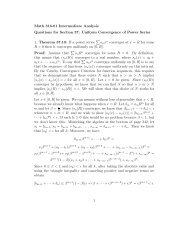
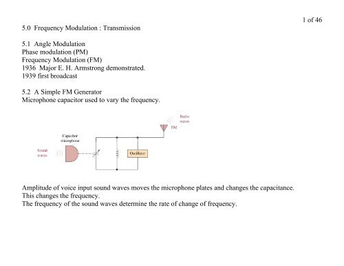
5.0 Frequency Modulation : <strong>Transmission</strong><br />
5.1 Angle Modulation<br />
Phase modulation (PM)<br />
Frequency Modulation (<strong>FM</strong>)<br />
1936 Major E. H. Armstrong demonstrated.<br />
1939 first broadcast<br />
5.2 A Simple <strong>FM</strong> Generator<br />
Microphone capacitor used to vary the frequency.<br />
Amplitude of voice input sound waves moves the microphone plates and changes the capacitance.<br />
This changes the frequency.<br />
The frequency of the sound waves determine the rate of change of frequency.<br />
1 of 46
fout<br />
= fc +k*ei<br />
2 of 46
Example 5.1<br />
25mV, 400Hz<br />
deviation constant 750Hz/10mV<br />
a) Frequency deviation generation by an input level of 25mV.<br />
750Hz*25mV/10mV = 1.875 kHz<br />
750Hz*-25mV/10mV = -1.875 kHz<br />
Total frequency deviation = +- 1.875 kHz<br />
Frequency deviation is 1.875 kHz<br />
b) Rate of deviation = +- 2.25kHz at a rate of 400Hz.<br />
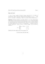
An <strong>FM</strong> system is transmitting the signal, v = 1000sin( 556x106t + 5sin(94x103t) )<br />
into a 50 ohm antenna. Determine,<br />
a) Carrier frequency 88.5 MHz<br />
b) Intelligence frequency 14.96 kHz<br />
c) Transmitted power 10002/2*50 = 10 kW<br />
e) Modulation index 5<br />
d) Frequency deviation 5*14.96 = 74.8 kHz<br />
In an <strong>FM</strong> transmitter, the output is changing between 89.003 and 88.997 MHz 1500 times a second. The<br />
intelligence signal is 3 volts peak. What is the deviation constant?<br />
Deviation constant = 3kHz/3V = 1kHz/V<br />
3 of 46
4 of 46<br />
An <strong>FM</strong> system is transmitting the signal, v = 1000sin( 556x106t + 5sin(94x103t) ) into a 50 ohm antenna.<br />
Determine the frequency deviation in kHz.<br />
5*14.96 = 74.8 kHz
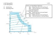
5.3 <strong>FM</strong> Analysis<br />
Phase Modulation<br />
e = Asin(ωct + mpsinωit)<br />
modulation index for PM = mp<br />
maximum phase shift caused by the intelligence signal<br />
Frequency Modulation<br />
e = Asin(ωct + mfsinωit)<br />
modulation index for <strong>FM</strong> = mf = δ/fi<br />
δ = maximum frequency shift caused by the intelligence signal<br />
5 of 46
6 of 46<br />
<strong>FM</strong> mathematical solution - infinite number of frequency components space at multiples of the intelligence<br />
frequency above & below fc. Bessel functions<br />
e(t) = A*fc(t) fc(t) are the frequency components<br />
fc(t) = J0(mf)*cosωct<br />
– J1(mf)[cos(wc – wi)t – cos(wc + wi)t]<br />
+ J2(mf)[cos(wc – 2wi)t – cos(wc + 2wi)t]<br />
– J3(mf)[cos(wc – 3wi)t – cos(wc + 3wi)t]<br />
+ J4(mf)[cos(wc – 4wi)t – cos(wc + 4wi)t]<br />
– J5(mf)[cos(wc – 5wi)t – cos(wc + 5wi)t]………………..
Bessel Functions<br />
EE3158 – Lecture 10 Fundamentals of Communications Slide 21<br />
7 of 46
8 of 46<br />
An <strong>FM</strong> system has a maximum deviation of 12 kHz. The maximum signal frequency is 3 kHz. Calculate<br />
the bandwidth required to transmit the <strong>FM</strong> signal by usng the Bessel function table below.<br />
21*2 = 42 kHz<br />
Carson’s rule<br />
BW is approx = 2(δmax + fimax)<br />
2% of the power is outside of the BW<br />
Using Carson’s rule?<br />
2(12 + 3) = 30 kHz
9 of 46<br />
An <strong>FM</strong> system has a maximum deviation of 60 kHz. The maximum signal frequency is 12 kHz. Calculate<br />
the bandwidth required to transmit the <strong>FM</strong> signal by using the Bessel function table.<br />
mod index = 5<br />
BW = 2*8*12 = 192kHz<br />
A 10kW <strong>FM</strong> transmitter has a modulation index of 5. Using the Bessel function table determine the power<br />
in the J3 sidebands.<br />
0.362*10kW = 1296W<br />
An <strong>FM</strong> signal has the following characteristics,<br />
modulation index 2.5<br />
signal frequency 1200Hz<br />
frequency deviation 3000Hz<br />
Determine,<br />
a) The bandwidth using the table.<br />
BW = 2 x 6 x 1.2kHz = 14.4kHz<br />
b) The bandwidth using Carson’s rule.<br />
BW = 2(3000 + 1200) = 8.4kHz
10 of 46
11 of 46<br />
A 10 kW <strong>FM</strong> transmitter has a modulation index of 2.5. Using the Bessel function table determine the<br />
power in,<br />
a) Carrier J0<br />
(-0.05)2(10kW) = 25 W<br />
b) Sidebands J5<br />
(0.02)2(10kW) = 4 W<br />
f the modulation index is 5 for a 10 KW transmitter determine the power in the,<br />
a) Carrier<br />
Pc = 0.18*0.18*10kW = 324W<br />
b) Highest significant sideband frequency<br />
P8 = 0.02*0.02*10kW = 4W
PSPICE Simulation<br />
V1 = 0<br />
V2 = 6.28<br />
TD = 0<br />
TR = 0.99m<br />
TF = .01m<br />
PW = 1m<br />
PER = 1m<br />
600mV<br />
400mV<br />
200mV<br />
V3<br />
0<br />
R1<br />
1k<br />
VOFF = 0<br />
VAMPL = 2.0<br />
FREQ = 100<br />
V4<br />
0V<br />
0Hz 0.2KHz<br />
V(SIN1:OUT)<br />
0.4KHz 0.6KHz 0.8KHz<br />
Frequency<br />
1.0KHz 1.2KHz 1.4KHz<br />
R2<br />
1k<br />
SIN<br />
R3<br />
1k<br />
V<br />
12 of 46
LabVIEW Simulation<br />
13 of 46
14 of 46
V1 = 0<br />
V2 = 6.28<br />
TD = 0<br />
TR = 0.99m<br />
TF = .01m<br />
PW = 1m<br />
PER = 1m<br />
600mV<br />
400mV<br />
200mV<br />
V3<br />
0<br />
R1<br />
1k<br />
VOFF = 0<br />
VAMPL = 2<br />
FREQ = 100<br />
0V<br />
0Hz 0.2KHz<br />
V(SIN1:OUT)<br />
0.4KHz 0.6KHz 0.8KHz<br />
Frequency<br />
1.0KHz 1.2KHz 1.4KHz<br />
V4<br />
R2<br />
1k<br />
SIN<br />
R3<br />
1k<br />
V<br />
15 of 46
Example 5.3<br />
Bandwidth required?? Using just the Table of significant components.<br />
<strong>FM</strong> signal fi = 10 kHz & δ = 20 kHz<br />
mf = δ/fi<br />
= 20 kHz/10 kHz<br />
= 2<br />
Looking at Table significant components are,<br />
Jo, J1, J2, J3, J4<br />
BW = 2( 4*fi)<br />
= 2(40 kHz<br />
= 80 kHz<br />
Compared with Carson’s rule (98% of the power) which is<br />
BW = 2(δ + fi)<br />
= 2(20 + 10)<br />
= 60 kHz<br />
16 of 46
An <strong>FM</strong> signal voltage applied to a 50-ohm load is, v(t) = 3000sin(2π*91.1(10 6 ) + 4sin(2000π))<br />
What is the,<br />
a) Signal frequency<br />
1000 Hz<br />
b) Frequency deviation<br />
4000 Hz<br />
c) Bandwidth using Carson’s rule.<br />
BW = 2(4000 + 1000) = 10,000 Hz<br />
Example 5.4<br />
Repeat with fi changed to 5 kHz<br />
mf = 20/5 = 4<br />
Significant J’s are throught 7<br />
BW = 2(7*5)<br />
= 2*35<br />
= 70 kHz<br />
vs. Carson’s rule<br />
BW = 2(20 + 5)<br />
= 50 kHz<br />
17 of 46
An <strong>FM</strong> signal has the following characteristics,<br />
modulation index 2.4<br />
signal frequency 1000Hz<br />
frequency deviation 4000Hz<br />
Determine,<br />
a) The bandwidth using the table below.<br />
BW = 2*5*1000 = 10,000Hz<br />
b) The bandwidth using Carson’s rule.<br />
BW = 2(4000 + 1000) = 10,000Hz<br />
18 of 46
Example 5.5<br />
<strong>FM</strong> sinal 2000sin(2π*10 8 t + 2sinπ*10 4 )t) applied to a 50ohm antenna<br />
a) Carrier frequency, fc<br />
fc = 10 8 Hz<br />
b) Transmitted power<br />
P = (2000*.707) 2<br />
50<br />
c) mf<br />
mf = 2<br />
d) Intelligence frequency<br />
fi = π*10 4/2 2π = 5kHz<br />
e) BW<br />
mf = δ/fi<br />
2 = δ/5kHz<br />
δ = 10kHz<br />
BW approx = 2(10kHz + 5kHz) = 30kHz<br />
f) Power in the largest and smallest sidebands from Table 5.2.<br />
19 of 46
The modulation index is 0.5 for a 10 KW transmitter.<br />
a) Determine the power in the carrier and all significant sideband frequencies<br />
Pc = 0.942(10,000) = 8.836W<br />
P1 = 2*0.242(10,000) = 1152W<br />
P2 = 2*0.032(10,000) = 18W<br />
b) What percentage of the 10KW is transmitted on frequencies where the power output level is not<br />
significant?<br />
20 of 46
Example 5.6<br />
a) Range of maximum modulation index for commercial <strong>FM</strong> where range of frequencies is<br />
30 Hz to 15 kHz<br />
mf = 75 kHz/100 Hz = 2500<br />
mf = 75 kHz/15 kHz = 5<br />
b) Repeat for a narrowband system where max deviation is 1 kHz.where range of requencies is<br />
100 Hz to 2 kHz<br />
mf = 1 kHz/100 Hz = 10<br />
mf = 1 kHz/2 kHz = 0.5<br />
c) Determine the DR for system in part b.<br />
DR = max deviation/max signal freq<br />
= 1 kHz/2 kHz = 0.5<br />
21 of 46
Example 5.7<br />
Determine the relative total power of the carrier and side frequencies when<br />
mf = 0.25 for a 10 kW <strong>FM</strong> transmitter<br />
for mf = 0.25<br />
J0 = 0.98<br />
J1 = 0.12<br />
and none other’s are significant<br />
power is proportional to voltage squared so<br />
0.98 2 * 10 kW = 9.604 kW<br />
0.12 2 * 10 kW = 144 W<br />
Total = 9.892 kW<br />
Total power must be constant<br />
Side frequency power is obtained from the carrier.<br />
No additional energy is added.<br />
22 of 46
Zero-Carrier Amplitude<br />
Broadcast <strong>FM</strong><br />
23 of 46
Deviation Ratio (DR)<br />
DR = maximum possible frequency deviation<br />
maximum input frequency<br />
DR (bradcast <strong>FM</strong> radio) = 75 kHz/15 kHz = 5<br />
DR (TV NTSC) = 25 kHz/15 kHz = 1.67<br />
24 of 46
5.4 Noise Suppression<br />
25 of 46
Phase shift due to noise, φ<br />
Frequency deviation<br />
δ = φ * fi intelligence signal frequency<br />
Looking at the INPUT signals and assume worst case, Right Angles to each other,<br />
sin φ = N / S where N = noise and S is desired signal<br />
φ = sin -1 N/S<br />
If the S/N is 2:1 and Fi maximum of 15 kHz, then<br />
φ = sin -1 ½ = 30 degrees = 0.52 radian<br />
δ = φ * fi = 0.52*15kHz = 7.5kHz<br />
26 of 46<br />
The output deviation at maximum signal frequency and max volume is 75kHz for broadcast <strong>FM</strong> (FCC reg).<br />
Thus the output deviation is 7.5kHz / 75kHz = 0.1 and the output Signal / Noise ratio is 10:1.<br />
This is compared to AM where a 2:1 ratio at the input is about that at the output.
<strong>FM</strong> Noise Analysis<br />
Capture Effect<br />
27 of 46
Preemphasis<br />
28 of 46
Emphasis Circuits<br />
29 of 46
Dolby Dynamic Preemphsis<br />
30 of 46
5.5 Direct <strong>FM</strong> Generation<br />
Varactor Diode<br />
31 of 46
32 of 46
33 of 46
LIC VCO <strong>FM</strong> Generation<br />
Philips Semiconductors NE/SE566 VCO<br />
Crosby Modulator (direct generation with AFC)<br />
Direct <strong>FM</strong> modulation<br />
Frequency multipliers<br />
Feedback to keep the carrier at center frequency<br />
Reactance modulator<br />
Restricted to less than +/- 1/1000 change in center frequency for linear operation<br />
5 MHz center frequency, +/- 4.167 kHz deviation<br />
Multiply by 18 to get,<br />
90 MHz center frequency, +/- 75 kHz deviation<br />
Discriminator feedback dc level to the reactance modulator (maintains 2 MHz difference between<br />
transmitted carrier and a crystal oscillator frequency)<br />
Crystal osc set at 88 MHz<br />
Difference from 2 MHz produces a dc voltage fed back to reactance modulator.<br />
34 of 46
35 of 46
5.6 Indirect <strong>FM</strong> Generation<br />
Armstrong type (limited frequency deviation)<br />
Modulation of a stable crystal oscillator<br />
JFET biased in ohmic region<br />
Voltage-controlled resistance<br />
Reactance modulator. Simple circuit below, but not enough deviation.<br />
36 of 46
Wideband deviation using Armstrong <strong>FM</strong> system<br />
37 of 46
38 of 46<br />
In an wideband Armstrong <strong>FM</strong> transmitter,<br />
a) A carrier at 400 kHz with a deviation of 14.47 Hz is input to a x81 frequency multiplier. What is the<br />
new carrier frequency and deviation at the output of the multiplier?<br />
32400 kHZ and 1172 Hz<br />
b) The output of the multiplier is fed to a mixer. The other input to the mixer comes from a 33.81 MHz<br />
oscillator. What is the new carrier frequency and deviation at the output of the mixer?<br />
1410 kHz and 1172 Hz
5.7 Phase-Locked-Loop <strong>FM</strong> Transmitter (Chapter 16.6 in Boylestad)<br />
A narrow band system (200 Hz),<br />
39 of 46
40 of 46
5.8 Stereo <strong>FM</strong><br />
Input to modulator<br />
Two separate 30 Hz to 15 kHz signals<br />
L + R 30 Hz-15 kHz<br />
L – R modulated with 38 kHz to 23-53 kHz<br />
pilot carrier at 19 kHz<br />
41 of 46
Stereo is more suseptable to noise than mono<br />
L-R is weaker<br />
L-R is at higher frequency<br />
S/N is 20 dB less than mono<br />
42 of 46<br />
Stereo received on mono receiver is only 1 dB worse S/N than mono received. This is due to the 19 kHz<br />
pilot.
5.9 <strong>FM</strong> <strong>Transmission</strong>s<br />
Table of frequencies<br />
Noncommercial broadcast 88 to 90 MHz<br />
Commercial broadcast 200 kHz 90 to 108 MHz<br />
Television audio 50 kHz 54 to 88 MHz, 174 to 216 MHz,<br />
470 to 806 MHz<br />
Narrowband public service 108 to 174 MHz, >806 MHz<br />
Narrowband amateur many<br />
Describe range of frequencies of operation (min/max) and bandwidth requirements for commercial<br />
broadcast of,<br />
a) AM 530-1700 kHz, 10 kHz<br />
b) <strong>FM</strong> 90-108 MHz, 200 kHz<br />
43 of 46
5.10 Troubleshooting<br />
44 of 46
45 of 46
46 of 46