4_DC Biasing BJTs - MavDISK
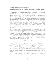
4_DC Biasing BJTs - MavDISK
4_DC Biasing BJTs - MavDISK

Create successful ePaper yourself
Turn your PDF publications into a flip-book with our unique Google optimized e-Paper software.
4_<strong>DC</strong> <strong>Biasing</strong> <strong>BJTs</strong><br />
4_<strong>DC</strong> <strong>Biasing</strong> <strong>BJTs</strong><br />
1 of 31<br />
4.1 Introduction<br />
Active or Linear Region Operation<br />
Base – Emitter junction is forward biased<br />
4.2 Operating Point<br />
Base – Collector junction is reverse biased<br />
Good operating point<br />
• Cutoff Region Operation<br />
Base – Emitter junction is reverse biased<br />
• Saturation Region Operation<br />
Base – Emitter junction is forward biased<br />
Base – Collector junction is forward biased
4_<strong>DC</strong> <strong>Biasing</strong> <strong>BJTs</strong> 2 of 31<br />
4.3 Fixed-Bias Circuit<br />
-VCE– ICRC + VCC = 0<br />
VCE = VCC – ICRC<br />
Base Loop (voltage drops)<br />
-VCC + IB RB + VBE = 0<br />
IB = (VCC – VBE)/RB
4_<strong>DC</strong> <strong>Biasing</strong> <strong>BJTs</strong> 3 of 31<br />
Fixed_base_current_load_line.obj simulation<br />
I1<br />
0.5mAdc<br />
400mA<br />
200mA<br />
Q1<br />
I<br />
Q2N2222<br />
0<br />
0Vdc<br />
V1<br />
R1<br />
40<br />
I<br />
10Vdc<br />
0A<br />
0V<br />
IC(Q1)<br />
1V<br />
-I(R1)<br />
2V 3V 4V 5V<br />
V_V1<br />
6V 7V 8V 9V 10V<br />
V2
4_<strong>DC</strong> <strong>Biasing</strong> <strong>BJTs</strong> 4 of 31<br />
Example 4.1<br />
Work through finding the base and collector currents.
4_<strong>DC</strong> <strong>Biasing</strong> <strong>BJTs</strong> 5 of 31<br />
Saturation Region<br />
Saturation – 0.2V is<br />
better approximation,<br />
but use 0V for now.<br />
ICsat = (VCC- 0)/RC<br />
and in active region,<br />
IC = β IB or IB = ICmax/β<br />
In saturation<br />
IB is greater than ICmax/β<br />
There is<br />
more base current than needed.
4_<strong>DC</strong> <strong>Biasing</strong> <strong>BJTs</strong> 6 of 31<br />
Bjt_resistor_bias.obj simulation<br />
5Vdc<br />
V1<br />
R1<br />
150k<br />
Q1<br />
Q2N2222<br />
0<br />
10Vdc<br />
V2<br />
5Vdc<br />
Run simulation and note voltages and currents.<br />
V3<br />
R2<br />
150k<br />
Q2<br />
Q2N2222<br />
0<br />
R3<br />
1k<br />
10Vdc<br />
V4
4_<strong>DC</strong> <strong>Biasing</strong> <strong>BJTs</strong> 7 of 31<br />
Saturation ....continued<br />
Modify Example 4.1<br />
Find ICmax<br />
Find RB minimum where transistor is on the edge of saturation.<br />
Reduce RB further and find base and collector currents.
4_<strong>DC</strong> <strong>Biasing</strong> <strong>BJTs</strong> 8 of 31<br />
Load-Line Analysis<br />
Maximum collector-emitter<br />
voltage occurs when IC equals<br />
zero.<br />
No drop across RC.<br />
Maximum current is<br />
ICsat = (VCC- 0)/RC<br />
Collector-emitter volage<br />
equlas zero.
4_<strong>DC</strong> <strong>Biasing</strong> <strong>BJTs</strong><br />
BJT_load_line.obj simulation<br />
9 of 31<br />
I1<br />
0Adc<br />
200mA<br />
100mA<br />
Q1<br />
I<br />
Q2N2222<br />
0<br />
0Vdc<br />
V1<br />
R1<br />
100<br />
I<br />
10Vdc<br />
V2<br />
0A<br />
0V<br />
IC(Q1)<br />
1V<br />
-I(R1)<br />
2V 3V 4V 5V<br />
V_V1<br />
6V 7V 8V 9V 10V
4_<strong>DC</strong> <strong>Biasing</strong> <strong>BJTs</strong> 10 of 31
4_<strong>DC</strong> <strong>Biasing</strong> <strong>BJTs</strong> 11 of 31
4_<strong>DC</strong> <strong>Biasing</strong> <strong>BJTs</strong> 12 of 31<br />
4.4 Emitter-Stabilized Bias Circuit<br />
Find the base current. Use Kirchhoff’s voltage around the base-emitter loop.
4_<strong>DC</strong> <strong>Biasing</strong> <strong>BJTs</strong> 13 of 31<br />
Show that,<br />
IC = β(VCC – VBE)<br />
RB + (β + 1)RE<br />
and when,<br />
RB
4_<strong>DC</strong> <strong>Biasing</strong> <strong>BJTs</strong> 14 of 31<br />
Use the base current equation to find the part of the input resistance due to the emitter resistor.<br />
Look at the loop equation written earlier<br />
VCC – IB RB – VBE - (β + 1)RE = 0<br />
Now draw the circuit that matches this equation,<br />
Note that the voltage drop across Re has not changed. The resistor Re is reflected back into the base input<br />
circuit and multiplied.
4_<strong>DC</strong> <strong>Biasing</strong> <strong>BJTs</strong> 15 of 31<br />
Collector-emitter loop<br />
Go around the loop and show the voltage relationships including<br />
VC, VE, and VB
4_<strong>DC</strong> <strong>Biasing</strong> <strong>BJTs</strong> 16 of 31<br />
R1<br />
20k<br />
R3<br />
R2<br />
10k<br />
100k<br />
Q1<br />
0<br />
Rc<br />
1k<br />
Q2N2222<br />
Re<br />
1k<br />
15Vdc<br />
Run simulation and note the voltages and currents.<br />
Vcc
4_<strong>DC</strong> <strong>Biasing</strong> <strong>BJTs</strong> 17 of 31<br />
Emitter-stabilized bias circuit for Example 4.4.<br />
Find the currents and voltages for this circuit.<br />
Review the load line for the circuit.<br />
Write the collect-emitter loop equation again and show the min and max current conditions.
4_<strong>DC</strong> <strong>Biasing</strong> <strong>BJTs</strong> 18 of 31<br />
4.5 Voltage-Divider Bias<br />
Show that by developing a Thevenin equivalent for the input the circuit becomes the same as the emitterstabilized<br />
circuit.
4_<strong>DC</strong> <strong>Biasing</strong> <strong>BJTs</strong> 19 of 31
4_<strong>DC</strong> <strong>Biasing</strong> <strong>BJTs</strong> 20 of 31<br />
4.6 Beta-stabilized circuit for Example 4.7.<br />
Work the circuit.
4_<strong>DC</strong> <strong>Biasing</strong> <strong>BJTs</strong> 21 of 31<br />
Common_base<br />
CB-1.obj simulation<br />
5Vdc<br />
V1<br />
R1<br />
1k<br />
CB-2.obj simulation<br />
3Vdc<br />
V1<br />
Q1<br />
Q2N2222<br />
3.5Vdc<br />
0<br />
Rc<br />
1.5k<br />
Rc1<br />
2.5k<br />
Vee<br />
Q1<br />
Q2N2222<br />
15Vdc<br />
0<br />
Vcc<br />
Rc<br />
1k<br />
12Vdc<br />
Vcc
4_<strong>DC</strong> <strong>Biasing</strong> <strong>BJTs</strong> 22 of 31<br />
Common Collector (Emitter Follower)<br />
CC-1.obj simulation<br />
5Vdc<br />
VB<br />
RB<br />
1k<br />
Q1<br />
CC-2.obj simulation<br />
5Vdc<br />
VB<br />
RB<br />
100k<br />
0<br />
0<br />
Q2N2222<br />
V<br />
Re<br />
1k<br />
Q1<br />
Q2N2222<br />
Re<br />
1k<br />
Re1<br />
1k<br />
12Vdc<br />
Vcc<br />
12Vdc<br />
Vcc
4_<strong>DC</strong> <strong>Biasing</strong> <strong>BJTs</strong> 23 of 31<br />
<strong>DC</strong> bias circuit with voltage feedback.
4_<strong>DC</strong> <strong>Biasing</strong> <strong>BJTs</strong> 24 of 31
4_<strong>DC</strong> <strong>Biasing</strong> <strong>BJTs</strong> 25 of 31<br />
Network for Example 4.11.
4_<strong>DC</strong> <strong>Biasing</strong> <strong>BJTs</strong> 26 of 31<br />
4.8 Design Operations<br />
Start with a set of transistor collector-emitter characteristics.<br />
Draw a load line.<br />
Determine the values of component values, voltages and currents.<br />
Perform for,<br />
Fixed bias circuit.<br />
Emitter-stabilized circuit.<br />
Voltage-divider circuit.
4_<strong>DC</strong> <strong>Biasing</strong> <strong>BJTs</strong> 27 of 31<br />
4.9 Transistor Switching Networks
4_<strong>DC</strong> <strong>Biasing</strong> <strong>BJTs</strong> 28 of 31
4_<strong>DC</strong> <strong>Biasing</strong> <strong>BJTs</strong> 29 of 31<br />
4.11 PNP Transistors<br />
Perform for,<br />
Fixed bias circuit.<br />
Emitter-stabilized circuit.
4_<strong>DC</strong> <strong>Biasing</strong> <strong>BJTs</strong> 30 of 31<br />
4.12 Bias Stabilization<br />
Shift in dc bias point (Q-point) due to change in<br />
temperature: 100 degrees C
4_<strong>DC</strong> <strong>Biasing</strong> <strong>BJTs</strong> 31 of 31<br />
4.13 Practical Applications<br />
Relay driver<br />
Transistor switch<br />
Constant current source - CB and CE configurations.