Power Introduction - MavDISK
Power Introduction - MavDISK
Power Introduction - MavDISK

Create successful ePaper yourself
Turn your PDF publications into a flip-book with our unique Google optimized e-Paper software.
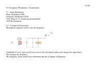
v(t) = Vmsin(ωt + θv)<br />
I(t) = Imsin(ωt + θi)<br />
POWER<br />
Rather than keep track of 2 angles we can use just 1,<br />
v(t) = Vmsin(ωt + θv- θi)<br />
I(t) = Imsin(ωt)<br />
Let θ = θv- θi<br />
And use rms values for V and I,<br />
Now we use trig identities and arrange this to be more usefull,<br />
p(t) = VIcosθ - VIcosθcos2ωt + VIsinθsin2ωt<br />
Point out,<br />
1) 2x freg of v(t)<br />
2) negative sometimes<br />
1 of 7
and<br />
P = VIcosθ watts<br />
Q = VIsinθ volt-amps reactive VARS<br />
<strong>Power</strong> for Resistor<br />
θv- θi = 0 o<br />
P = VIcos0 o<br />
= VI = I 2 R = V 2 /R<br />
<strong>Power</strong> for Inductor<br />
θv- θi = 90o because current lags voltage<br />
P = VIcos(90 o ) = 0 watts<br />
Q = VIsin(90 o ) = VI = I 2 ωL = V 2 /ωL vars<br />
The average reactive power is zero.<br />
<strong>Power</strong> for Capacitor<br />
θv- θi = 90o because current leads voltage<br />
P = VIcos(-90 o ) = 0 watts<br />
Q = VIsin(-90 o ) = -VI = -I 2 (1/ωC) = -V 2 ωC vars<br />
vars<br />
The average reactive power is zero.<br />
2 of 7
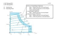
<strong>Power</strong> Factor<br />
pf = cos(θv- θi) = cosθ<br />
The pf is a number between 0 & 1.<br />
We say the circuit is either leading or lagging.<br />
Resistor and inductor<br />
Current lags voltage<br />
VARS are positive<br />
Phase angle (θv - θi) is positive<br />
Pf = …... lagging<br />
Resistor and capacitor<br />
Current leads voltage<br />
VARS are negative<br />
Phase angle is negative<br />
Pf = ….. leading<br />
3 of 7
Complex <strong>Power</strong><br />
S = P + jQ<br />
|S|=VI<br />
P = VIcosθ<br />
Q = VIsinθ<br />
Resistor and inductor and voltage source (DRAW),<br />
I = V∠0 o<br />
R + jωL<br />
VI = V( V )<br />
(R 2 + (ωL) 2 ) 1/2 ∠tan-1 ωL/R)<br />
VI = V( V ∠- tan-1 ωL/R)<br />
(R 2 + (ωL) 2 ) 1/2<br />
Remember that the phase angle of power is,<br />
Phase angle of voltage minus phase angle of current.<br />
S = V•I *<br />
S = V( V ∠(-1)(-1) tan-1 ωL/R)<br />
(R 2 + (ωL) 2 ) 1/2<br />
= V 2 ∠tan -1 (ωL/R)<br />
(R 2 + (ωL) 2 ) 1/2<br />
4 of 7
Notice that the angle is positive and is the same result as<br />
when currents are used in the calculation.<br />
S = Ieff 2 (R + jωL)<br />
= V 2 •(R 2 + (ωL) 2 ) 1/2 ∠ tan -1 (ωL/R)<br />
(R 2 + (ωL) 2 ) 1/2 •(R 2 + (ωL) 2 ) 1/2<br />
P = Ieff 2 R<br />
Q = I 2 (jωL)<br />
S = I 2 (R 2 + (ωL) 2 ) 1/2 ∠ tan -1 (ωL/R)<br />
Resistor and capacitor and voltage source,<br />
I = V∠0 o<br />
R + 1/jωC<br />
= V∠0 o<br />
R - j/ωC<br />
S = V•I *<br />
= V∠0 o x V∠0 o<br />
R + j/ωC<br />
= V 2 ∠-tan -1 (1/ωRC)<br />
(R 2 + (1/ωC) 2 ) 1/2<br />
Notice that the angle is negative and is the same result as<br />
when currents are used.<br />
5 of 7
S = I 2 (R + 1/jωC) = I 2 (R - j/ωC)<br />
= V 2 •(R 2 + (1ωC) 2 ) 1/2 ∠- tan -1 (1/ωRC)<br />
(R 2 + (1/ωC) 2 ) 1/2 •(R 2 + (1/ωC) 2 ) 1/2<br />
P = I 2 R<br />
Q = I 2 (-j/ωC)<br />
S = I 2 (R 2 + (1/ωC) 2 ) 1/2 ∠ -tan -1 (1/ωRC)<br />
Inductive circuit<br />
Lagging power factor<br />
Absorbing VARS<br />
Capacitive circuit<br />
Leading power factor<br />
Generating VARS<br />
More on the conjugate story,<br />
S = P + jQ<br />
S = V•I *<br />
= (V∠θv) • (I∠θi) *<br />
= (V• I∠(θv-θi)<br />
6 of 7
For example, a simple resistor-inductor circuit,<br />
2amp rms at 30deg<br />
V2<br />
1 2<br />
j30<br />
0<br />
The voltage, V, across the resistor and inductor is,<br />
V = (2∠30 o) ( 40 + j30) rms<br />
S = V•I *<br />
= (2∠30 o )( 40 + j30)( 2∠30 o ) *<br />
= (2∠30 o )( 40 + j30)( 2∠-30 o )<br />
= (4)( 40 + j30)<br />
40<br />
7 of 7<br />
Now the 30 degree angle which is common to both the voltage and<br />
current has been eliminated from the calculation.