Negative index of refraction
Negative index of refraction
Negative index of refraction

You also want an ePaper? Increase the reach of your titles
YUMPU automatically turns print PDFs into web optimized ePapers that Google loves.
University <strong>of</strong> Ljubljana<br />
Faculty <strong>of</strong> Mathematics and Physics<br />
Department <strong>of</strong> Physics<br />
<strong>Negative</strong> <strong>index</strong> <strong>of</strong> <strong>refraction</strong><br />
Seminar<br />
Author: Matej Bobnar<br />
Advisor: pr<strong>of</strong>. dr. Martin Čopič<br />
May 2006<br />
Abstract<br />
First, I present theory behind the negative <strong>refraction</strong>, which was introduced<br />
by Victor Veselago in 1968. I describe how negative permeability<br />
and permittivity lead to negative refractive <strong>index</strong> and some consequent<br />
phenomena: reversed Doppler and Cerenkov effect, different types <strong>of</strong> lens.<br />
Next I propose how materials with negative permittivity and permeability<br />
can be made. Finaly, I describe some experiments and present measurements<br />
with such materials. They verify theoretical predictions.<br />
1
Contents<br />
1 Introduction 3<br />
2 Refraction at the boundry <strong>of</strong> a substence with ɛ < 0 and<br />
µ < 0 3<br />
2.1 Doppler effect . . . . . . . . . . . . . . . . . . . . . . . . . . 5<br />
2.2 The Cerenkov effect . . . . . . . . . . . . . . . . . . . . . . 5<br />
2.3 Lens with the negative <strong>index</strong> <strong>of</strong> <strong>refraction</strong> . . . . . . . . . . 6<br />
3 The search for materials with negative <strong>index</strong> <strong>of</strong> <strong>refraction</strong> 7<br />
3.1 Materials with negative ɛ or µ . . . . . . . . . . . . . . . . . 7<br />
3.2 Metamaterials . . . . . . . . . . . . . . . . . . . . . . . . . . 9<br />
4 Experimental verification <strong>of</strong> a negative <strong>index</strong> <strong>of</strong> <strong>refraction</strong> 11<br />
5 Conclusion 14<br />
2
1 Introduction<br />
Victor Veselago, in a paper published in 1968 [1], pondered the consequences<br />
for electromagnetic waves interacting with a hypothetical material<br />
for which both the electric permittivity ɛ and the magnetic permeability<br />
µ were simultaneously negative. Because no naturally occurring material<br />
or compound has ever been demonstrated with negative ɛ and µ, Veselago<br />
wondered whether this apparent asymmetry in material properties was<br />
just happenstance or perhaps had a more fundamental origin. He concluded<br />
that not only should such materials be possible, but if ever found,<br />
they would exhibit remarkable properties unlike those <strong>of</strong> any known materials.<br />
He termed these materials ”left-handed” (LHM). Among many<br />
properties <strong>of</strong> LHMs are <strong>index</strong> <strong>of</strong> negative <strong>refraction</strong>, reversed Doppler and<br />
Cerenkov effect and other.<br />
In the last decade the fabrication and measurement <strong>of</strong> structured metamaterial<br />
having a range <strong>of</strong> frequencies over which the refractive <strong>index</strong> was<br />
predicted to be negative for one direction <strong>of</strong> propagation were reported<br />
[2], [3]. These structures use split ring resonators [4] to produce negative<br />
magnetic permeability over a particular frequncy region and wire elements<br />
to produce negative electric permittivity in an overlapping frequency region.<br />
One must choose the negative root <strong>of</strong> the <strong>index</strong> <strong>of</strong> <strong>refraction</strong> given<br />
by n = ± √ ɛµ. The experiments [2], [3] confirm that LHMs do indeed<br />
exhibit negative <strong>refraction</strong>.<br />
2 Refraction at the boundry <strong>of</strong> a substence<br />
with ɛ < 0 and µ < 0<br />
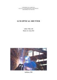
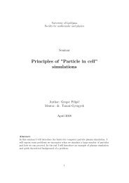
Figure 1: Passage <strong>of</strong> a ray through the boundry between two media <strong>of</strong> different<br />
handedness.<br />
At first it seems as if the refractive <strong>index</strong> should not change if both<br />
the electric permittivity and the magnetic permeability are both less than<br />
zero. But at closer look, we see that we have to take the minus sign from<br />
3
the square root <strong>of</strong> ɛ and µ. We conclude this, not from the wave equation,<br />
but rather directly from Maxwell equations and the constitutive relations:<br />
rotE = − 1 ∂B<br />
,<br />
c ∂t<br />
(1)<br />
rotB = 1 ∂D<br />
,<br />
c ∂t<br />
(2)<br />
B = µH, (3)<br />
D = ɛE. (4)<br />
For a plane monochromatic wave in which all quantities are proportional<br />
to e ı(kz−ωt) the upper expressions reduce to:<br />
k × E = ω<br />
µH, (5)<br />
c<br />
k × H = − ω<br />
ɛE. (6)<br />
c<br />
E, H and k form a right-handed triplet <strong>of</strong> vectors if ɛ > 0 and µ > 0 and<br />
if ɛ < 0 and µ < 0 they form a left-handed set.<br />
Independently <strong>of</strong> the handedness <strong>of</strong> the two media, the rays passing<br />
from one medium to another must satisfy the boundry conditions [5]:<br />
Et1 = Et2, Ht1 = Ht2,<br />
ɛ1En1 = ɛ2En2, µ1Hn1 = µ2Hn2.<br />
From the first two follows that the x and y components <strong>of</strong> the fields E<br />
and H in the refracted ray maintain their directions whatever the handedness<br />
<strong>of</strong> the two media. However the z components change sign, if the<br />
handednesses are diffrent. This happens because in this case the vectors<br />
E and H undergo a reflection relative to the interface <strong>of</strong> the two media.<br />
They also change in magnitude if ɛ and µ differ in their absolute value.<br />
The energy flux carried by the wave is determined by the Poynting<br />
vector S:<br />
S = c<br />
E × H. (8)<br />
4π<br />
The energy can not pile up on the boundry and is therefore flowing<br />
ahead into the medium. Therefore the Poynting vector is directed into<br />
the medium and because the fields E and H are reflected at the boundry<br />
it also lies on the same side <strong>of</strong> the z axis as before <strong>refraction</strong>.<br />
The paralel phase (the paralel component <strong>of</strong> the wave vector, k||) must<br />
also remain the same at the boundry. From that fact and the direction <strong>of</strong><br />
the Poynting vector we conclude that the wave vector is directed in the<br />
opposite direction as is the Poynting vector. Effectivly, this means that<br />
the wave vector is also reflected across the boundry <strong>of</strong> the two media.<br />
If all three vectors are reflected at the same time, then they form a<br />
left-handed set. The path <strong>of</strong> the refracted ray is shown in Fig. 1. So when<br />
the second medium is left-handed the refracted ray lies on the opposite<br />
side <strong>of</strong> the z axis as it would in the normal medium. The direction <strong>of</strong><br />
the reflected ray however is always the same. When the handedness <strong>of</strong><br />
medium 1 and 2 are diffrent, we have to correct the usual Snell’s law:<br />
sin α p2<br />
= n1,2 =<br />
sin β p1<br />
<br />
<br />
<br />
<br />
ɛ2µ2<br />
ɛ1µ1<br />
(7)<br />
<br />
<br />
<br />
, (9)<br />
where the quantity p = 1 for a right-handed medium and p = −1 for<br />
a left-handed medium. From above equation we can see that the <strong>index</strong><br />
4
<strong>of</strong> <strong>refraction</strong> can be negative if the handednesses <strong>of</strong> the two media are<br />
diffrent. The amplitudes <strong>of</strong> reflected and refracted light are found by<br />
applying Fresnel’s formulas [6]. A special case is that <strong>of</strong> a ray passing<br />
from the medium with ɛ1 > 0 and µ1 > 0 into the medium with ɛ2 = −ɛ1<br />
and µ2 = −µ1. We see that the ray is refracted at the boundry, but there<br />
is no reflection.<br />
From that we can see that for right-handed substances S and k are<br />
in the same direction and for left-handed substances they are in opposite<br />
directions. By their directions are also defined group and phase velocities,<br />
vector k is in the direction <strong>of</strong> the phase velocity and S in the direction<br />
<strong>of</strong> group velocity. This reversal <strong>of</strong> phase and group velocity in a medium<br />
implies a simply stated but pr<strong>of</strong>ound consequence: The sign <strong>of</strong> the refractive<br />
<strong>index</strong>, n , must be taken as negative. So the statement: ”left-handed<br />
material” is equivalent to: ”material with the negative <strong>index</strong> <strong>of</strong> <strong>refraction</strong>.”<br />
2.1 Doppler effect<br />
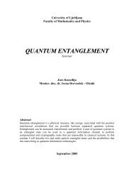
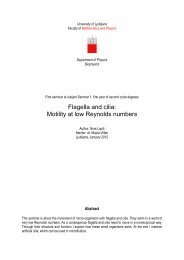
Figure 2: a) Doppler effect in a right-handed substance; b) Doppler effect in a<br />
left-handed substance. A - source <strong>of</strong> radiation; B - the receiver [1].<br />
First we look at the Doppler shift in the left-handed substance. It is<br />
reversed. Suppose that a detector <strong>of</strong> radiation situated in the left-handed<br />
material moves relative to a source (for example it is approaching to a<br />
source) which emits a frequncy ω0. Since the phase velocity is reversed<br />
the detector will see the phase <strong>of</strong> radiation as if it would be coming from<br />
the other side, as is shown in Fig. 2. The frequency received by the<br />
detector will thus be smaller then ω0, not larger like it would be in a<br />
normal medium. Upgraded formula for the Doppler shift is now:<br />
ω = ω0(1 − p v<br />
), (10)<br />
c<br />
where the velocity <strong>of</strong> the detector v is positive when it is receding from<br />
the source.<br />
2.2 The Cerenkov effect<br />
Just like the Doppler effect, the Cerenkov effect will also be reversed. A<br />
particle moving in a medium with velocity v in a straight line will emit<br />
according to the law e ı(kzz+krr−ωt) . The wave vector <strong>of</strong> the radiation will<br />
be given by k = kz/cosθ and is in the general direction <strong>of</strong> the velocity v.<br />
However kr will be different in different media:<br />
<br />
kr = p| k2 2 − kz|. (11)<br />
5
Figure 3: a) The Cerenkov effect in a right-handed substance; b) The same<br />
effect in a left-handed substance [1].<br />
In a left-handed medium the vector kr will be directed toward the trajectory<br />
<strong>of</strong> the particle because the energy moves away from the particle to<br />
infinity. The cone <strong>of</strong> radiation will be directed backward relative to the<br />
motion <strong>of</strong> the particle. The angle between v and S will be:<br />
<br />
<br />
<br />
c2 cos θ = p <br />
v2n2 <br />
<br />
<br />
. (12)<br />
<br />
2.3 Lens with the negative <strong>index</strong> <strong>of</strong> <strong>refraction</strong><br />
Figure 4: Paths <strong>of</strong> rays through a) convex and b) concave lenses made <strong>of</strong> lefthanded<br />
substances, situated in vacuum [1].<br />
For the lenses made <strong>of</strong> negative <strong>index</strong> material the paths <strong>of</strong> rays<br />
through them are shown in Fig. 4. It is seen that the concave and convex<br />
lenses have changed places, since the convex lens has a diverging effect<br />
and the concave lens a converging effect. Also for thin lenses, geometrical<br />
optics - valid for either positive or negative <strong>index</strong> - gives the result<br />
that the focal length f is related to the lens’s radius <strong>of</strong> curvature, R, by<br />
f = R/(n−1). The denominator in the focal-length formula implies an inherent<br />
distinction between positive- and negative-<strong>index</strong> lenses: A material<br />
with n = +1 does not refract electromagnetic fields, whereas a material<br />
with n = −1 does. The result is that negative-<strong>index</strong> lenses can be more<br />
compact.<br />
With negative refractive <strong>index</strong> material we can also achieve a focusing<br />
effect by a simple slab <strong>of</strong> it [1]. <strong>Negative</strong> <strong>refraction</strong> by a slab <strong>of</strong> material<br />
(n = −1) bends a ray <strong>of</strong> light back toward the axis and thus has a focusing<br />
effect at the point where the refracted rays meet the axis which turns out<br />
6
Figure 5: Passage <strong>of</strong> rays <strong>of</strong> light through through a plate <strong>of</strong> thickness d made<br />
<strong>of</strong> a left-handed substance. A - source <strong>of</strong> radiation, B - detector <strong>of</strong> radiation<br />
to be twice. This is revealed by a simple ray diagram. Light transmited<br />
through a slab <strong>of</strong> thickness l, located a distance d1 from the source comes<br />
to a second focus when,<br />
d2 = l − d1. (13)<br />
The other relevant quantity, the impedance <strong>of</strong> the medium,<br />
Z =<br />
<br />
µ<br />
Z0, Z0 =<br />
ɛ<br />
µ0<br />
ɛ0<br />
(14)<br />
retains its positive sign, so that when both ɛ = −1 and µ = −1, the<br />
medium is a perfect match to free space and interfaces show no reflection.<br />
This can also be seen from the following relation for reflectivity:<br />
r =<br />
<br />
Z<br />
Z0<br />
Z<br />
Z0<br />
− 1<br />
+ 1<br />
2<br />
, (15)<br />
where Z0 is the impedance <strong>of</strong> the vacuum. At the far boundry there<br />
is again an impedance match and the light is perfectly transmited into<br />
vacuum. This however is not a lens in the usual sense because it will not<br />
focus at a point a bundle <strong>of</strong> rays coming from infinity.<br />
3 The search for materials with negative<br />
<strong>index</strong> <strong>of</strong> <strong>refraction</strong><br />
3.1 Materials with negative ɛ or µ<br />
First, we take a look at a Drude-Lorentz model [5], [10] <strong>of</strong> a material (Fig.<br />
6), which conceptually replaces the atoms and moleculs <strong>of</strong> a real material<br />
by a set <strong>of</strong> harmonically bound electron oscillators resonant at some frequency<br />
ω0. At frequencies far below ω0, an applied electric field induces<br />
a polarization in the same direction as the applied field. At frequencies<br />
7
Figure 6: Typical behaviour <strong>of</strong> the real and imaginary parts <strong>of</strong> the dielectric<br />
constant for a Lorentz model <strong>of</strong> a material.<br />
near resonance, the induced polarization becomes very large, as is typical<br />
in resonance phenomena; the energy is accumulated over many cycles, so<br />
that a considerable amount <strong>of</strong> energy is stored in the resonator relative<br />
to the driving field. As the frequency <strong>of</strong> the driving electric field is swept<br />
through the resonance, the polarization flips from in-phase to out-<strong>of</strong>-phase<br />
with the driving field, and the material exhibits a negative response. If<br />
instead <strong>of</strong> electrons the material response were due to harmonically bound<br />
magnetic moments, then a negative magnetic response would exist.<br />
<strong>Negative</strong> materials are quite easy to find. Materials with negative ɛ<br />
include metals (such as silver, gold, and aluminum) at optical frequencies.<br />
Materials with negative µ include resonant ferromagnetic or antiferromagnetic<br />
systems.<br />
However, since negative material parameters occur near a resonance,<br />
there are three important consequences:<br />
1. <strong>Negative</strong> material parameters will exhibit frequency dispersion. In<br />
fact, it can be seen from the relation<br />
w = ɛɛ0E 2 + µµ0H 2<br />
(16)<br />
that when there is no frequency dispersion nor absorption we cannot<br />
have ɛ < 0 and µ < 0, since in that case the energy density would<br />
be negative[1], [7]. When there is frequency dispersion, the above<br />
relation must be replaced by<br />
w = ∂(ɛω)<br />
∂ω ɛ0E2 + ∂(µω)<br />
∂ω µ0H2 . (17)<br />
In order for the energy w to be positive it is reqired that<br />
∂(ɛω)<br />
∂ω<br />
> 0,<br />
∂(µω)<br />
∂ω<br />
> 0. (18)<br />
2. There will always be absorption. If ɛ ′ and µ ′ are negative (real part<br />
<strong>of</strong> the permittivity and permeability) than, according to Kramers-<br />
Kronig relations [5], the imaginary part <strong>of</strong> the permittivity (ɛ ′′ ) and<br />
<strong>of</strong> the permeability (µ ′′ ) are non-zero in the left-handed material.<br />
3. The usable bandwidth <strong>of</strong> negative materials will be relatively narrow<br />
compared with positive materials.<br />
8
This is why materials with ɛ and µ both negative are not found in<br />
nature. In existing materials, the resonances that give rise to electric<br />
polarizations typically occur at very high frequencies - in the optical for<br />
metals, and at least in the terahertz-to-IR region for semiconductors and<br />
insulators. On the other hand, resonances in magnetic systems typically<br />
occur at much lower frequencies and usually tail <strong>of</strong>f toward the THz and<br />
IR region [9].<br />
3.2 Metamaterials<br />
Figure 7: Sinusni val<br />
Metamaterials are artificial structures. To form an artificial material,<br />
we start with a collection <strong>of</strong> repeated elements designed to have a strong<br />
response to applied electromagnetic fields. As long as the size and spacing<br />
<strong>of</strong> the elements are much smaller than the electromagnetic wavelengths <strong>of</strong><br />
interest, incident radiation cannot distinguish the collection <strong>of</strong> elements<br />
from a homogeneous material. We can thus conceptually replace the inhomogeneous<br />
composite by a continuous material described by material<br />
parameters ɛ and µ. At lower frequencies, conductors are excellent candidates<br />
from which to form artificial materials, because their response to<br />
electromagnetic fields is large.<br />
To construct the material with negative ɛ we use a periodic array <strong>of</strong><br />
thin conducting wires (Fig. 8(a)). The wire medium can be characterized<br />
by frequency dependent permittivity having the Drude-Lorentz form [3]<br />
ɛ(ω) = 1 −<br />
ω 2 ep<br />
ω 2 − ω 2 e0<br />
+ ıγω , (19)<br />
for which ωep is the electric plasma frequency, ωe0 is a resonant frequency<br />
and γ is a damping factor. In naturally occuring metals, ωep is typically<br />
in visible-UV range, being determined by the inherent properties <strong>of</strong> the<br />
conduction charge carriers. In the thin wire medium, however, ωep is determined<br />
by radii, spacing and self-inductance <strong>of</strong> the wires, and can be<br />
scaled to virtually any frequency below which the permittivity is negative<br />
with relatively low damping. Structures are <strong>of</strong>ten designed with continuous<br />
wires so that ωe0 = 0.<br />
To build a medium that would respond magnetically to electromagnetic<br />
radiation, a periodic array <strong>of</strong> conducting split ring resonators (SRRs)<br />
9
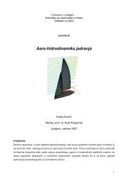
(a) A periodic array <strong>of</strong> thin conducting<br />
wires.<br />
(b) A periodic array <strong>of</strong> conducting split<br />
ring resonators - SRRs.<br />
Figure 8: The basic building blocks <strong>of</strong> LHM metamaterials [3].<br />
were introduced [4]. A SRR (Fig. 8(b)) is made <strong>of</strong> two concentric conducting<br />
rings, cut on opposite sides. They are like miniature circuits: A<br />
time-varying magnetic field induces an electromotive force in the plane <strong>of</strong><br />
the element, driving currents within the conductor. A gap in the plane<br />
<strong>of</strong> the structure introduces capacitance into the planar circuit and gives<br />
rise to a resonance at frequency set by the geometry <strong>of</strong> the element. The<br />
effective permeability <strong>of</strong> the SRR medium is <strong>of</strong> the form [4]:<br />
µ(ω) = 1 −<br />
F ω 2<br />
ω 2 − ω 2 m0<br />
+ ıγω<br />
(20)<br />
in which F is constant between zero and unity and ω 2 m0 is a magnetic<br />
resonant frequency.<br />
A metamaterial formed by combining the wire and SRR media possesses<br />
unexpected and unique electromagnetic properties, including negative<br />
<strong>index</strong> <strong>of</strong> <strong>refraction</strong>.<br />
10
4 Experimental verification <strong>of</strong> a negative<br />
<strong>index</strong> <strong>of</strong> <strong>refraction</strong><br />
Figure 9: Planar wave, launched down the rectangular waveguide, interacts with<br />
a metamaterial sample placed at the center <strong>of</strong> the circular plates. The detector,<br />
confined to the radius by a bearing mounted arm, sweeps around circumference<br />
<strong>of</strong> the plates. Absorber (black) is placed inside the plates to minimize reflective<br />
scattering [2].<br />
The design <strong>of</strong> the experimental apparatus is shown in the Fig.<br />
9. It is based on a planar waveguide geometry, with a central chamber<br />
formed by two semicircular aluminum plates, joined to an extended channel<br />
formed by two rectangular aluminum plates. The samples occupy a<br />
small region near the center <strong>of</strong> the central chamber and are exited by a<br />
beam launched from the extended chamber.<br />
Figure 10: A unit cell <strong>of</strong> LHM on the left and on the right a negative <strong>index</strong><br />
material formed by SRRs and wires deposited on opposite sides lithographically<br />
on standard circuit board [9].<br />
The left-handed material used in experiments is usually a two or<br />
one dimensional periodic array <strong>of</strong> copper SRRs and wires on fiber glass<br />
circuit board material. They are assembled and than cut into desired<br />
shape, e.g. a prism for a beam deflection experiments. Fig. 10 depicts a<br />
one unit cell and many <strong>of</strong> them assembled to form a 2D array.<br />
Transmisson measurement [3] uses rectangular slabs <strong>of</strong> three types:<br />
wires only; SRRs only; wires and SRRs together. Forward transmittance<br />
11
(a) Transmited power versus frequency<br />
through a metamaterial composed <strong>of</strong><br />
wires (solid black) and a metamaterial<br />
composed <strong>of</strong> SRRs (dashed black).<br />
The raw data is superimposed as grey<br />
curves. This results were obtained on<br />
a one-dimensional array <strong>of</strong> SRRs and<br />
wires.<br />
(b) Measured power through metamaterial<br />
composed <strong>of</strong> SRRs and wires. For<br />
comperison, the spectra for SRRs only<br />
and wires only is also shown.<br />
Figure 11: The results <strong>of</strong> the measurement <strong>of</strong> the transmission through a slab<br />
<strong>of</strong> LHM [3].<br />
is measured as a function <strong>of</strong> frequency. From Fig. 11(a) we see that as expected<br />
the transsmited power for SRRs only and wires only is substantially<br />
lowered around the resonance region. However, for both media combined<br />
we see on Fig. 11(b) that where the individual resonances overlap we get<br />
increased transmission.<br />
Refractive properties <strong>of</strong> the metamaterial sample are investigated<br />
with a wedge fashioned from the SRR and wire unit cells shown in Fig.<br />
12. The angular power distribution from the empty chamber, a Teflon<br />
Figure 12: Schematic <strong>of</strong> the one-dimensionally isotropic wedge design based on<br />
a 5mm unit cell.<br />
wedge control sample and the SRR/wire metamaterial is compared on Fig.<br />
13. The wedge angle for the Teflon was 34 ◦ . Using this angle with the<br />
12
measured peak angle corresponding to the Teflon sample (17.5 ◦ ) yieldes<br />
a value for the refractive <strong>index</strong> <strong>of</strong> n = 1.4 [3].<br />
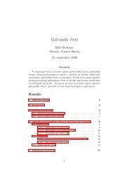
Over the frequency band corresponding to the transmission peak in<br />
Fig. 11(b), the angular power distribution coresponding to the metamaterial<br />
was peaked at angles negative with respect to the surface normal;<br />
that is, the metamaterial indeed behaved as if it had a negative refractive<br />
<strong>index</strong>. This metamaterial sample, the 3-over-1 cut corresponds to 18.4 ◦<br />
for the average wedge angle. The two peaks shown in Fig. 13 correspond<br />
to two different frequencies within the band, showing the dispersive nature<br />
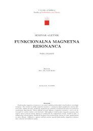
<strong>of</strong> the negative <strong>index</strong>. This angle with the measured peak angle allowes an<br />
Figure 13: Detected power versus angle for the empty chamber (grey), a Teflon<br />
wedge (right hand curve), and the negative <strong>index</strong> metamaterial sample wedge<br />
(left hand curves) [3].<br />
effective refractive <strong>index</strong> to be computed for the metamaterial, which is<br />
shown on the Fig. 14 . Because this metamaterial sample was anisotropic,<br />
it is the square root <strong>of</strong> ɛzµx that is actually being determined.<br />
13
Figure 14: The refractive <strong>index</strong> <strong>of</strong> the metamaterial sample as a function <strong>of</strong><br />
frequency (solid line). The measured peak power <strong>of</strong> the refracted beam (dashed<br />
line) [3].<br />
5 Conclusion<br />
<strong>Negative</strong> <strong>refraction</strong> is a subject with constant capacity for surprise: Innocent<br />
assumptions lead to unexpected and sometimes pr<strong>of</strong>ound consequences.<br />
This new field has generated great enthusiasm but also controversy,<br />
yet even the controversies have had the positive effect that key<br />
concepts have been critically scrutinized. In the past years, experimental<br />
data have been produced that validate the concepts. As a result, there<br />
is a firm foundation on which to build. Many groups are already moving<br />
forward with applications. The microwave area has naturally been most<br />
productive, because the metamaterials required are easier to fabricate.<br />
In addition to microwave lenses, novel waveguides and other devices are<br />
under consideration. We are not yet done with theory, because the assumption<br />
<strong>of</strong> negative <strong>refraction</strong> has many ramifications that are still being<br />
explored and are sure to cast more light on this strange but fascinating<br />
subject.<br />
References<br />
[1] V.G. Veselago, The electrodynamics <strong>of</strong> substances with simultaneously<br />
negative values <strong>of</strong> ɛ and µ, Sov. Phys. Uspekhi, vol 10, No.4, 509<br />
(1968).<br />
[2] R.A. Shelby, D.R. Smith, S. Schultz, Experimental verification <strong>of</strong> a<br />
negative <strong>index</strong> <strong>of</strong> <strong>refraction</strong>, Science, vol.292, 77, (2001).<br />
[3] D.R. Smith, P. Rye, D.C. Vier, A.F. Starr, J.J. Mock, T. Perram,<br />
Design and measurement <strong>of</strong> anisotropic metamaterials that exhibit<br />
negative <strong>refraction</strong>, IEICE TRANS. ELECTRON., vol. E87-C, NO.3,<br />
359, (2004).<br />
14
[4] D.R. Smith, et al., Composite medium with simultaneously negative<br />
permeability and permittivity, Phys. Rev. Lett. Vol.84, No.18, (2000)<br />
[5] Rudi Podgornik, Elektromagnetno polje<br />
[6] D.R. Smith, S. Schultz, P. Markos, C.M. Soukoulis, Determination<br />
<strong>of</strong> effective permittivity and permeability <strong>of</strong> materials from reflection<br />
and transmission coefficients, Phys. Rew. B, Vol.65, 195104, (2002).<br />
[7] P. Markos and C.M. Soukoulis, Structures with negative <strong>index</strong> <strong>of</strong> <strong>refraction</strong>,<br />
Phys. Stat. Sol. (a) 197, No. 3, 595, (2003).<br />
[8] D.R. Smith, J.B. Pendry, M.C.K. Wiltshire, Metamaterials and negative<br />
refractive <strong>index</strong>, Science vol 305, 788, (6. Aug. 2004)<br />
[9] J.B. Pendry and D.R. Smith, Reversing light with negative <strong>refraction</strong>,<br />
Physics today, (Jun. 2004)<br />
[10] N.W. Ashcr<strong>of</strong>t, N.D. Mermin, Solid state physics, Saunders College<br />
Publishing, (1975).<br />
15