BiPort Manual 12.rsp - M-Audio
BiPort Manual 12.rsp - M-Audio
BiPort Manual 12.rsp - M-Audio
Create successful ePaper yourself
Turn your PDF publications into a flip-book with our unique Google optimized e-Paper software.
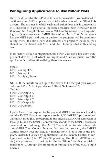
Configuring Applications to Use <strong>BiPort</strong> 2x4s<br />
Once the drivers for the <strong>BiPort</strong> 2x4s have been installed, you will need to<br />
configure your MIDI applications to take advantage of the <strong>BiPort</strong> 2x4s<br />
drivers. The manner in which each application does this is different, so<br />
it is impossible to go over all possible scenarios here. However, most<br />
Windows MIDI applications have a MIDI configuration or settings dialog<br />
box (sometimes called “MIDI Devices” or “MIDI Tools”) that specifies<br />
the MIDI input and output devices the program will be communicating<br />
with. If your <strong>BiPort</strong> 2x4s drivers are properly installed, you<br />
should see the <strong>BiPort</strong> 2x4s MIDI and SMPTE ports listed in this dialog<br />
box.<br />
In its factory default configuration, the <strong>BiPort</strong> 2x4s looks like eight independent<br />
devices, 3 of which are inputs and 5 are outputs. From the<br />
application’s configuration dialog, these devices are:<br />
Inputs<br />
<strong>BiPort</strong> 24s Input A<br />
<strong>BiPort</strong> 24s Input B<br />
<strong>BiPort</strong> 24s Sync/Status<br />
NOTE: If the inputs are set up in the driver to be merged, you will see<br />
only one <strong>BiPort</strong> MIDI input device: “<strong>BiPort</strong> 24s In A+B+S”.<br />
Outputs<br />
<strong>BiPort</strong> 24s Output A<br />
<strong>BiPort</strong> 24s Output B<br />
<strong>BiPort</strong> 24s Output C<br />
<strong>BiPort</strong> 24s Output D<br />
<strong>BiPort</strong> 24s Control<br />
Inputs A and B correspond to the physical MIDI In connectors A and B,<br />
and the SMPTE/Status corresponds to the 1/4” SMPTE Input connector.<br />
Outputs A through D correspond to the physical MIDI Out connectors A<br />
through D, and the SMPTE Control corresponds to the SMPTE processor<br />
command port. Although the SMPTE/Status driver transfers time code<br />
data (MIDI Time Code to be specific) into the program, the SMPTE<br />
Control driver does not actually transfer SMPTE data out of the program.<br />
Instead, it is used by applications like the Remote Control to configure<br />
and control (Start Writing, Stop Writing, User Bits, SMPTE format,<br />
etc.) the processor that resides inside the <strong>BiPort</strong> 2x4s. If you wish to<br />
transmit MTC through the <strong>BiPort</strong>, do it through one of the MIDI output<br />
devices.<br />
35


