Create successful ePaper yourself
Turn your PDF publications into a flip-book with our unique Google optimized e-Paper software.
LAGOON<br />
MANUAL<br />
LAGOON <br />
TM
Table of Contents<br />
Introduction . . . . . . . . . . . . . . . . . . . . . . . . . . . . . . . . . . . . . . . . . . . . . . . .3<br />
Features . . . . . . . . . . . . . . . . . . . . . . . . . . . . . . . . . . . . . . . . . . . . . . . . . . .3<br />
Included Drivers: . . . . . . . . . . . . . . . . . . . . . . . . . . . . . . . . . . . . . . . . .3<br />
Minimum System Requirements . . . . . . . . . . . . . . . . . . . . . . . . . . . . . . . . .4<br />
What’s in the Box? . . . . . . . . . . . . . . . . . . . . . . . . . . . . . . . . . . . . . . . . . . .4<br />
The Lagoon Card . . . . . . . . . . . . . . . . . . . . . . . . . . . . . . . . . . . . . . . . . . . .4<br />
Installation . . . . . . . . . . . . . . . . . . . . . . . . . . . . . . . . . . . . . . . . . . . . . . . . .5<br />
Checking IRQs . . . . . . . . . . . . . . . . . . . . . . . . . . . . . . . . . . . . . . . . . . . . . .5<br />
Hardware Installation . . . . . . . . . . . . . . . . . . . . . . . . . . . . . . . . . . . . . . . . .6<br />
Windows Driver and Software Installation . . . . . . . . . . . . . . . . . . . . . . . . .7<br />
Windows 98 Installation . . . . . . . . . . . . . . . . . . . . . . . . . . . . . . . . . . .7<br />
Windows 95 Installation . . . . . . . . . . . . . . . . . . . . . . . . . . . . . . . . . . .7<br />
Verifying Windows Driver Installation . . . . . . . . . . . . . . . . . . . . . . . . .8<br />
Software Installation . . . . . . . . . . . . . . . . . . . . . . . . . . . . . . . . . . . . . .8<br />
Verifying Lagoon Tools Applet Software Installation . . . . . . . . . . . . . .9<br />
Setting Up Your Digital Studio . . . . . . . . . . . . . . . . . . . . . . . . . . . . . . . . . .9<br />
Using LAGOON with Application Software . . . . . . . . . . . . . . . . . . . . . . .11<br />
The LAGOON Tools Applet . . . . . . . . . . . . . . . . . . . . . . . . . . . . . . . . . . .12<br />
Info Page . . . . . . . . . . . . . . . . . . . . . . . . . . . . . . . . . . . . . . . . . . . . . . . . . .13<br />
General Page . . . . . . . . . . . . . . . . . . . . . . . . . . . . . . . . . . . . . . . . . . . . . . .13<br />
Mode . . . . . . . . . . . . . . . . . . . . . . . . . . . . . . . . . . . . . . . . . . . . . . . . .14<br />
Clock Source . . . . . . . . . . . . . . . . . . . . . . . . . . . . . . . . . . . . . . . . . . .14<br />
Sample Rate . . . . . . . . . . . . . . . . . . . . . . . . . . . . . . . . . . . . . . . . . . . .15<br />
Advanced Page . . . . . . . . . . . . . . . . . . . . . . . . . . . . . . . . . . . . . . . . . . . . .15<br />
Consumer Mode . . . . . . . . . . . . . . . . . . . . . . . . . . . . . . . . . . . . . . . .16<br />
Professional Mode . . . . . . . . . . . . . . . . . . . . . . . . . . . . . . . . . . . . . . .16<br />
MME Page . . . . . . . . . . . . . . . . . . . . . . . . . . . . . . . . . . . . . . . . . . . . . . . .17<br />
ASIO Page . . . . . . . . . . . . . . . . . . . . . . . . . . . . . . . . . . . . . . . . . . . . . . . .18<br />
MIDI Page . . . . . . . . . . . . . . . . . . . . . . . . . . . . . . . . . . . . . . . . . . . . . . . .19<br />
Status Page . . . . . . . . . . . . . . . . . . . . . . . . . . . . . . . . . . . . . . . . . . . . . . . .19<br />
Input Errors . . . . . . . . . . . . . . . . . . . . . . . . . . . . . . . . . . . . . . . . . . . .20<br />
Output Error . . . . . . . . . . . . . . . . . . . . . . . . . . . . . . . . . . . . . . . . . . .22<br />
MIDI Errors . . . . . . . . . . . . . . . . . . . . . . . . . . . . . . . . . . . . . . . . . . . .23<br />
Sample Rates and Per<strong>for</strong>mance . . . . . . . . . . . . . . . . . . . . . . . . . . . . .24<br />
Troubleshooting . . . . . . . . . . . . . . . . . . . . . . . . . . . . . . . . . . . . . . . . . . . .25<br />
Lifetime Limited Warranty . . . . . . . . . . . . . . . . . . . . . . . . . . . . . . . . . . . .26
FCC Class B / European CE Compliance<br />
WARNING: This equipment has been tested and found to comply with the limits <strong>for</strong><br />
a CLASS B digital device, pursuant to Part 15 of the FCC Rules. These limits are<br />
designed to provide reasonable protection against harmful interference in a<br />
residential installation. This equipment generates, uses and can radiate radio<br />
frequency energy and, if not installed and used in accordance with the instructions<br />
contained in this manual, may cause harmful interference to radio and television<br />
communications. However, there is no guarantee that interference will not occur in<br />
a particular installation.<br />
If this equipment does cause harmful interference to radio or television reception,<br />
which can be determined by turning the equipment off and on, the user is encouraged<br />
to try to correct the interference by one or more of the following measures:<br />
1) reorient or relocate the receiving antenna; 2) increase the separation between the<br />
equipment and the receiver; 3) connect the equipment into an outlet on a circuit<br />
different from that of the receiver; 4) consult the dealer or an experienced audio<br />
television technician.<br />
NOTE: Connecting this device to peripheral devices that do not comply with<br />
CLASS B requirements or using an unshielded peripheral data cable could also<br />
result in harmful interference to radio or television reception.<br />
The user is cautioned that any changes or modifications not expressly approved by<br />
the party responsible <strong>for</strong> compliance could void the user‘s authority to operate this<br />
equipment.<br />
To ensure that the use of this product does not contribute to interference, it is<br />
necessary to use shielded I/O cables.<br />
This product also complies with European CE requirements.<br />
2
Introduction<br />
Congratulations on your purchase of a LAGOON PCI Digital <strong>Aud</strong>io Card! With this card,<br />
high-quality digital audio processing becomes possible with your PC. The card offers<br />
optical digital I/O and an ADAT Sync connector (standard Alesis 9-pin DB connector).<br />
The optical digital I/Os may be software-configured to S/PDIF or ADAT mode while<br />
supporting Full Duplex <strong>for</strong> simultaneous record and playback (e.g. simultaneous<br />
recording from ADAT and playing back over S/PDIF is possible) The S/PDIF mode<br />
supports several sample rates and sample resolutions up to 24 Bit at 96 kHz. Using ADAT,<br />
you may record and play back simultaneously 8 channels of digital audio at up to 51 kHz<br />
and 24 Bit. Using the ADAT Sync, synchronization to your ADAT recorder is easy. If this<br />
is not needed, this connector can alternately be used as a MIDI In/Out interface by simply<br />
plugging in the included MIDI adapter cable.<br />
Beyond these versatile interfacing possibilities the Motorola 56301 DSP used on this card<br />
offers 80 MIPS of DSP computing power. Combined with 768 kBytes of fast EDO<br />
DRAM, a variety of audio effects may be run on this system with simultaneous digital I/O<br />
operation.<br />
Features<br />
Low profile PCI card (requires PCI BIOS version 2.1).<br />
Operates in Full Duplex <strong>for</strong> simultaneous record and playback.<br />
Onboard Motorola 56301 running at 80 MHz, delivering 80 MIPS computing power.<br />
Onboard 768 kByte fast EDO-DRAM to ensure reliable audio streaming and effects.<br />
Onboard DSP supports downloadable audio effects and processing.<br />
1 Toslink Optical In and 1 Toslink Optical Out supports the following I/O modes:<br />
• ADAT 8-Channel Optical<br />
All ADAT word widths up to 24 bit<br />
ADAT sample rates from 39 kHz to 51 kHz<br />
• S/PDIF Optical<br />
All word widths up to 24 bit<br />
Sample rates: 32, 44.1, 48, 64, 88.2, 96 kHz<br />
Consumer or Professional mode<br />
• Mixed mode: S/PDIF In and ADAT Out or ADAT In and S/PDIF Out<br />
ADAT Sync In or MIDI Options via 9-pin DB connector supports:<br />
•ADAT Sync In using standard Alesis ADAT Sync cables.<br />
•1 In and 1 Out MIDI Interface<br />
Uses supplied break out cable to connect to MIDI devices.<br />
Allows <strong>for</strong> MTC or MIDI clock synchronization through user application software.<br />
Included Drivers:<br />
•Windows 95/98 MME driver<br />
Supports Mono, Stereo, 8-channel and MIDI devices<br />
•Windows 95/98 ASIO driver<br />
3
Minimum System Requirements<br />
• Windows 95 or 98<br />
• Pentium 166 or higher with MMX, 200 MHz recommended.<br />
• 32 MByte RAM, 64 MByte recommended.<br />
What’s in the Box?<br />
Your LAGOON box contains:<br />
• This Instruction Manual<br />
• The LAGOON PCI card<br />
• 1x1 MIDI Interface Cable<br />
• Diskettes <strong>for</strong> Windows 95/98 installation<br />
• Midiman Warranty Registration Card<br />
Important: Please fill out the included Warranty Registration Card<br />
and mail or fax it to us as soon as possible. Registering your<br />
LAGOON will help us to give you the best possible service and<br />
support.<br />
1.<br />
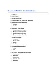
The Lagoon Card<br />
2.<br />
3.<br />
1. ADAT Sync Input/MIDI I/O: This 9-pin DB female connector will accept the<br />
synchronization output of an ADAT tape recorder. Switching the K9 jumper on<br />
the Lagoon board will alter the function of this connector to a 1 in/1 out MIDI<br />
interface (see #4 in this list). Shown here MIDI cable is attached.<br />
2. Toslink Optical Input: This standard female Toslink input jack accepts a standard<br />
male Toslink plug, either ADAT 8-channel <strong>for</strong>mat output or S/PDIF 2-channel<br />
<strong>for</strong>mat output as configured in the Lagoon Tools Applet (see section, “Lagoon<br />
Tools Applet”).<br />
4<br />
4.
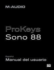
3. Toslink Optical Output: This standard female Toslink output jack accepts a<br />
standard male Toslink plug, typically connected to either an ADAT 8-channel<br />
<strong>for</strong>mat input or S/PDIF 2-channel <strong>for</strong>mat input (as configured in the Lagoon<br />
Tools Applet).<br />
4. ADAT Sync/MIDI Jumper: (see section, “Hardware Installation”).<br />
Installation<br />
Here is a list of the steps required to get your LAGOON PCI Digital <strong>Aud</strong>io Card up<br />
and running. Please read the associated section of the manual and follow the<br />
instructions carefully.<br />
1. Check the Computer Properties in your Windows Device Manager <strong>for</strong> an<br />
available IRQ <strong>for</strong> the LAGOON to install to. Although the LAGOON supports<br />
shared IRQs it is desirable the LAGOON gets its own IRQ so that can properly<br />
interact with the computer’s microprocessor (see “Checking IRQs”).<br />
2. Physically install the LAGOON card in your computer (see “Hardware<br />
Installation”).<br />
3. Install drivers and support software (see “Windows Driver and Software<br />
Installation”).<br />
4. Attach the LAGOON to other pieces of equipment in your studio (see “Setting<br />
Up Your Digital Studio”).<br />
5. Configure your application software to properly communicate with the<br />
LAGOON PCI (see “Using LAGOON with Application Software”).<br />
Checking IRQs<br />
The LAGOON PCI Digital <strong>Aud</strong>io Card needs an Interrupt Request line, or IRQ<br />
(basically, a line of communication between the LAGOON and the microprocessor)<br />
to function properly. It is best to check <strong>for</strong> IRQ availability be<strong>for</strong>e installing a new<br />
device, as it will prevent resource conflicts that may be otherwise avoidable.<br />
Open the Windows Control Panel (Start|Settings|Control Panel). Double click the<br />
“System” icon, then click the Device Manager tab. The word “Computer” will be<br />
highlighted (if not, highlight “Computer”). Click “Properties.” This will bring up<br />
the Computer Properties screen, with a list of IRQs on the left, and devices on the<br />
right. If a number does NOT show up in the list, it means that it is available <strong>for</strong> use.<br />
The IRQ numbers 5, 9, 10, and 11 are most often the ones to look to <strong>for</strong> availability,<br />
although 3, 4, 7, 12, and 15 may also be a possibility (depending on your system’s<br />
configuration). IRQs 3 and 4 are often used <strong>for</strong> the COM Ports (this is controlled by<br />
the system’s BIOS), and are sometimes instructed by the BIOS to receive a “Legacy<br />
ISA” device rather than a PCI or ISA “PnP” (Plug and Play) device. This is<br />
discussed later in the section “Troubleshooting”, though you may want to consult<br />
your computer’s user guide <strong>for</strong> more in<strong>for</strong>mation.<br />
Once you have determined that there is an IRQ available <strong>for</strong> the LAGOON card, it<br />
is safe to proceed to the next step, which is to physically install the LAGOON.<br />
5
Hardware Installation<br />
To physically install the LAGOON card into your computer, please do the following:<br />
1. Turn off your computer.<br />
2. Remove the <strong>cover</strong> and position the computer so that you can easily access<br />
its PCI slots.<br />
3. Select the PCI slot into which you will install your LAGOON card. PCI slots are<br />
distinguishable from ISA slots by being shorter and set back farther from the<br />
outside of the computer. If you’re still unsure, consult your computer or<br />
mainboard user’s guide.<br />
4. The PCI slot you just selected should have a metal bracket associated with it that<br />
<strong>cover</strong>s the PCI slot’s access hole on the back of the computer. This bracket is<br />
usually fastened to the computer with a single screw. Remove the screw and<br />
bracket- be sure not to lose the screw as you will need it later!<br />
5. Be<strong>for</strong>e removing the LAGOON from its protective antistatic bag, touch the metal<br />
power supply case of the computer in order to dissipate any static electricity<br />
charge your body may have accumulated.<br />
6. Remove the plastic terminators that are plugged into the optical jacks of the<br />
LAGOON card. This is only possible be<strong>for</strong>e inserting the card !<br />
7. Set the jumper K9 corresponding to your demands (see picture below). When<br />
using the LAGOON MIDI cable, close K9 <strong>for</strong> proper cable shielding. When<br />
using an ADAT Sync cable, do not close K9 to avoid ground loops.<br />
K9<br />
closed <strong>for</strong> MIDI open <strong>for</strong> ADAT<br />
8. Position the LAGOON card over the target PCI slot and fit the card loosely over<br />
it with the LAGOON card upright. Press the card gently but firmly downward<br />
into the slot until the card is completely and squarely seated in the slot. If the card<br />
seems difficult to seat, a slight rocking motion may help. If the card is impossible<br />
to seat, you may be trying to install the LAGOON in a non-PCI slot. If this is the<br />
case, go back to Step 3.<br />
9. Once the LAGOON card is firmly seated, fasten its metal bracket down into the<br />
computer chassis, using the screw you removed in Step 4 above.<br />
10. Place the <strong>cover</strong> back on your computer.<br />
6<br />
K9
Windows Driver and Software Installation<br />
The Lagoon PCI includes a Windows 98/95 diskette containing the Windows<br />
drivers, ASIO drivers, and Lagoon Tools Applet software. To install these on your<br />
system, please follow these steps:<br />
Windows 98 Installation<br />
1. After installing the Lagoon hardware, boot your system and start Windows.<br />
During the Windows boot procedure, new hardware will be automatically<br />
detected by the Add New Hardware Wizard as shown here. Click ‘Next>’.<br />
2. The ‘Add New Hardware Wizard’ will now ask how you want to find the driver.<br />
“Search <strong>for</strong> the best driver <strong>for</strong> your device” is already selected. Click ‘Next>’.<br />
3. Windows will give you a selection of locations to search. Make sure that ‘Floppy<br />
disk drives’ is checked, or click on the check box to do so. Insert the Lagoon<br />
95/98 Driver and Tools Applet Disk #1 into your floppy drive. Click ‘Next>’.<br />
4. The ‘Wizard’ reports that its Windows driver file search has found the Lagoon<br />
<strong>Aud</strong>iocard. Click ‘Next>’.<br />
5. Windows is now ready to install the driver files from the specified location.<br />
Click ‘Next>’. Windows will start to copy the files and show you a progress<br />
report screen.<br />
6. The Wizard reports that Windows has finished installing the software. Click<br />
‘Finish’. Your Lagoon is ready <strong>for</strong> action.<br />
After completion of the driver installation, Windows may require you to restart<br />
Windows. If it does request a restart, remove the Lagoon Disk from the floppy disk<br />
drive and respond ‘Yes’. The system will restart and you are ready to install the<br />
Lagoon Tools Applet software.<br />
Windows 95 Installation<br />
1. After installation of the Lagoon hardware, boot your system and start<br />
Windows. During the Windows boot procedure, new hardware will be<br />
automatically detected.<br />
2. Choose the Install of “driver from disk provided by hardware<br />
manufacturer,” then click ‘OK’.<br />
3. An ‘Install From Disk’ will prompt you to copy files from the A:\ drive<br />
(if your floppy drive is a different drive letter, then change it at this<br />
time). Insert the Lagoon 95/98 Driver and Tools Applet Disk #1 into the<br />
drive then click ‘OK’.<br />
4. Windows will start to copy files, with a progress indicator on the screen.<br />
Once this process completes itself, you will be ready to install the<br />
Lagoon Tools Applet.<br />
After completion of the driver installation, Windows may require you to restart<br />
Windows. If it does request a restart, remove the Lagoon Disk from the floppy disk<br />
drive and click ‘Yes,’ and the system will restart.<br />
7
Verifying Windows Driver Installation<br />
Windows displays the Lagoon driver status in the Device Manager page of the<br />
System Properties dialog box. The Device Manager page is opened via the Windows<br />
Start button: select Start | Settings | Control Panel | System | Device Manager. With<br />
the Device Manager displayed, click on the “+” next to “Sound, video and game<br />
controllers” to open a list of devices, the Lagoon being a device of that nature.<br />
Below is an example view of the Device Manager.<br />
This example shows the M <strong>Aud</strong>io Lagoon and Midiman WINMAN 4x4/S (another<br />
product shown here only as an example) entries in the Windows Device Manager<br />
device list. The Lagoon is properly installed with no conflicts, as is the WINMAN<br />
4x4/S. If you do not see your M <strong>Aud</strong>io Lagoon in your Device Manager in this<br />
fashion, please jump ahead to the “Troubleshooting” section of this manual.<br />
Software Installation<br />
Once the Lagoon driver software is installed in your system, you are ready to install<br />
the Lagoon Tools Applet. The Lagoon Tools are necessary to properly control the<br />
functions of the card, as well as monitor the status of your digital signal.<br />
1. Insert the Lagoon 95/98 Driver and Tools Applet Disk #1 into your floppy drive. Open<br />
your Start menu and select ‘Run’. Type in the path, “A:\Setup”. Click ‘OK’.<br />
2. The Lagoon Tools installer will say “Welcome to Lagoon Tools Setup.”<br />
Click ‘OK’.<br />
3. Lagoon Setup will ask you to “Select Components and Folder.” We suggest clicking<br />
‘OK’ and installing the defaults, which will create a Lagoon folder in your Programs<br />
8
folder on your C: drive, install the Multimedia and ASIO drivers, plus install a groovy<br />
monophonic virtual analog synthesizer. This synth is the first of a series of<br />
synthesizers and effects that will be made available <strong>for</strong> the Lagoon as they are<br />
developed. Click ‘OK’.<br />
4. Lagoon Setup will allow you to select a folder into which to install the Tools<br />
Applet software. Again, we suggest just sticking with the “Lagoon” folder, but<br />
advanced users can make another selection here. Click ‘OK’.<br />
5. The “Ready to Start” dialog box will display the components you have selected<br />
<strong>for</strong> installation. Clicking “Allow Setup to reboot your system automatically” is<br />
suggested. Click ‘Start’ to begin installing.<br />
6. When Setup prompts, insert the Lagoon 95/98 Driver and Tools Applet Disk #2<br />
into your floppy drive. Click ‘OK’.<br />
7. When installation is completed, your system will reboot. If you had not<br />
selected the automatic reboot option, Lagoon Setup will give you the<br />
option to do so at the completion of the installation. Once you have<br />
rebooted, the Lagoon Setup will return and announce that setup is<br />
complete. Click ‘Finish’ and the Lagoon Tools Applet will appear<br />
opened on your desktop. Your Lagoon is now ready <strong>for</strong> use.<br />
Verifying Lagoon Tools Applet Software Installation<br />
After completing the Lagoon Tools setup, the Lagoon Tools Applet will appear on<br />
your desktop. Refer to section 5, “The Lagoon Tools Applet” <strong>for</strong> more in<strong>for</strong>mation<br />
on its use with your Lagoon card. If you’ve chosen to install the virtual synthesizer,<br />
you will see a “Synth-A” button on the Info page that is currently open. Clicking on<br />
that button will open the Synth-A controls. Clicking on the question mark in the<br />
upper right-hand corner (?) will open up an Info page with a “Manual” button that<br />
will open the Synth-A manual readme file. You may open the File menu and select<br />
‘Print’ if you wish to print this out <strong>for</strong> easy reference.<br />
A Lagoon icon should now exist on your Windows taskbar, which is your quick and<br />
easy access to your applet software. Clicking on the X in the upper right-hand<br />
corner of the applet will close it<br />
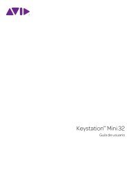
Setting Up Your Digital Studio<br />
Once the LAGOON PCI Digital <strong>Aud</strong>io Card is installed in your computer, you are<br />
ready to make the necessary connections to external devices. The following setups,<br />
1-3, illustrate several configurations in which the LAGOON is most often used.<br />
The LAGOON is an extremely versatile card that can be used in a number of<br />
configurations. You may find yourself using one or more setups while<br />
recording, and a different setup when mixing down. To avoid having to patch<br />
and repatch inputs and outputs, it may be reasonable to consider the purchase<br />
of a digital patchbay such as Midiman’s Digipatch 12x6. A Typical LAGOON<br />
ADAT Setup follows this section.<br />
9
1. Connect the LAGOON PCI Toslink Optical Output to the Input of your<br />
receiving device.<br />
a) If you are sending a 2-channel signal, your recieving device may be the<br />
S/PDIF digital input of a stereo amplifier or mixer, DAT mixdown deck, or<br />
stereo D/A converter (such as Midiman’s Flying Calf D/A or the M <strong>Aud</strong>io<br />
SuperDAC). A D/A converter will convert the digital signal to analog,<br />
which would allow input to the same types of analog receiving devices.<br />
b) If you are sending an 8-channel signal to the LAGOON PCI Toslink Optical<br />
Output, your receiving device may be the optical input of an ADAT, 8channel<br />
optical input of a digital mixer, or the optical input of an 8-channel<br />
D/A converter.<br />
2. Connect the outputs of your digital source to the LAGOON PCI Toslink<br />
Optical Input.<br />
a) If your source is 2-channel optical, this may be the digital outputs of a DAT<br />
deck, CD player, digital mixer, or A/D converter (such as the Midiman<br />
Flying Calf A/D) that is converting the analog outputs of a similar source<br />
to a 2-channel digital signal.<br />
b) If your source is 8-channel optical, this may be an ADAT optical output, the<br />
8-channel optical buss outs of a digital mixer, or the 8-channel optical<br />
output of an A/D converter.<br />
3. Connect either the Sync Output of your ADAT recorder or the supplied MIDI<br />
breakout cable to the 9-pin DB connector. The LAGOON will provide either<br />
ADAT Sync or MIDI In and Out (depending on the jumper settings), controlled<br />
by the LAGOON Tools applet (see section, “The LAGOON Tools Applet”).<br />
a) If you are using ADATs in your system, the sync output of the last ADAT<br />
in your chain should be connected to the 9-pin DB connector. This will<br />
allow the Lagoon to receive a sync signal from the ADATs, making the<br />
ADATs the sync “master,” and your computer the sync “slave.”<br />
b) This 9-pin connector can alternately be used as a 1 In, 1 Out MIDI<br />
interface. A MIDI interface will allow you to record and playback<br />
in<strong>for</strong>mation from your MIDI compatible keyboards and sound modules, as<br />
well as open up synchronization possibilities using MIDI sync (MTC or<br />
MIDI clock).<br />
optical IN<br />
optical out<br />
Sync-IN/MiDi<br />
10<br />
optical IN<br />
optical out<br />
Sync OUT<br />
ADAT<br />
Typical LAGOON ADAT Setup
Using LAGOON with Application Software<br />
Once the Lagoon’s hardware, driver software, and Tools Applet are properly<br />
installed, it is ready <strong>for</strong> use with your music application software. Some of these<br />
applications may require you to highlight or enable the Lagoon drivers within the<br />
program, and others may have a utility that analyzes or profiles the audio cards in<br />
your system and enables the drivers. Your software should have an audio device<br />
driver setup page, as well as a MIDI driver setup page.<br />
NOTE: If you have selected S/PDIF as your input or output <strong>for</strong>mat,<br />
this will dedicate the software input and output devices 1 and 2<br />
(1/2) <strong>for</strong> use with your S/PDIF signal. When selecting S/PDIF as<br />
your input signal, choose Lagoon in 1/2 (or ADAT1 1/2 <strong>for</strong> ASIO)<br />
as the source within your music software. Set your output port to<br />
Lagoon out 1/2 (or ADAT1 1/2) when selecting S/PDIF as your<br />
output <strong>for</strong>mat (see section 5, “Lagoon Tools Applet” <strong>for</strong><br />
in<strong>for</strong>mation on making these selections).<br />
WINDOWS MME AUDIO INPUT DEVICES: The Lagoon optical input may be<br />
used <strong>for</strong> a total of either 2 (S/PDIF) or 8 (ADAT) input channels. Within your<br />
software application(s), the names of the possible Lagoon audio input devices are:<br />
Lagoon in 1/2<br />
Lagoon in 3/4<br />
Lagoon in 5/6<br />
Lagoon in 7/8<br />
The Lagoon input devices allow recording a stereo (S/PDIF) or 8-channel (ADAT)<br />
stream directly from the optical input specified in the Lagoon Tools software (see<br />
Lagoon Tools Applet section). Note that all of the input devices are stereo. Your<br />
application software may break these down further to “left” and “right” mono<br />
devices. There<strong>for</strong>e you may see them as “Left Lagoon in 1/2, Right Lagoon in 1/2,<br />
Left Lagoon in 3/4, Right Lagoon in 3/4,” etc., from within your recording software.<br />
WINDOWS MME AUDIO OUTPUT DEVICES: All Lagoon optical outputs<br />
may be used simultaneously <strong>for</strong> a total of 2 (S/PDIF) or 8 (ADAT) output<br />
channels. Within your software application(s), the names of the Lagoon<br />
audio output devices are:<br />
Lagoon out 1/2<br />
Lagoon out 3/4<br />
Lagoon out 5/6<br />
Lagoon out 7/8<br />
All Lagoon output devices allow playing a stereo audio stream to the hardware<br />
optical output. Your application software may break each of these stereo devices<br />
down further to “left” and “right” mono devices. There<strong>for</strong>e you may see them as<br />
“Left WavOut 1/2 Lagoon, Right WavOut 1/2 Lagoon,” or “Left WavOut S/PDIF<br />
Lagoon, Right WavOut S/PDIF Lagoon,” etc. from within your music software.<br />
Other software will handle the outputs as stereo pairs, but allow you to pan audio left<br />
or right within the pair.<br />
11
ASIO DRIVER INPUT DEVICES: When using the ASIO audio drivers with<br />
programs that support ASIO-style audio, the input devices are displayed as mono<br />
devices. Within ASIO software applications, the names of the Lagoon audio input<br />
devices are:<br />
ADAT1 1/2<br />
ADAT1 3/4<br />
ADAT1 5/6<br />
ADAT1 7/8<br />
ASIO DRIVER OUTPUT DEVICES: The Lagoon’s ASIO output devices appear in<br />
stereo pairs. Because each device is stereo, you may see “left” and “right”<br />
references within your software application. This allows the application to pan<br />
audio left and right under software control. To send a signal to a Lagoon ASIO<br />
output 1 (<strong>for</strong> example) as a mono output send, one would choose “Analog 1/2<br />
Lagoon” <strong>for</strong> that track’s output port, and then pan that output hard left. The ASIO<br />
outputs are named as follows:<br />
ADAT1 1/2<br />
ADAT1 3/4<br />
ADAT1 5/6<br />
ADAT1 7/8<br />
WINDOWS MULTIMEDIA SETTINGS: Windows may be set up to use the<br />
Lagoon as its default audio device, allowing system sounds to be sent out the<br />
Lagoon. This also enables you to use the Lagoon with the sound applets<br />
included with Windows. To set this up, go to Control Panel | Multimedia. In<br />
the <strong>Aud</strong>io Properties page, set the Playback and Recording devices to the<br />
Lagoon input and output devices of your choice.<br />
The LAGOON Tools Applet<br />
Using the LAGOON Tools you may configure the operation mode of the LAGOON<br />
card. The LAGOON Tools may be easily accessed by clicking on the LAGOON icon<br />
in the taskbar (alternately you can access them by clicking on the corresponding<br />
entry in the Windows Start menu / Programs). Moreover, this icon provides<br />
in<strong>for</strong>mation about the status of the card. If it is permanently blue, everything is OK.<br />
If the icon starts blinking red/blue, an error has occurred. By clicking on this icon<br />
and selecting the Status page you can easily check what kind of error occurred. But<br />
let‘s start with the basic Info page.<br />
12
Info Page<br />
The Info page provides in<strong>for</strong>mation about the installed drivers. In the screen shot<br />
above you can see that the driver version is 1.4 (you probably have a newer one) and<br />
that both the MME and ASIO drivers are installed. This can be modified by clicking<br />
on the button named Start setup to modify.<br />
You will further notice two small buttons in the upper right corner of the LAGOON<br />
Tools window. The right one is as usual <strong>for</strong> closing the LAGOON Tools. The left one<br />
has a special function. If you click on it, the LAGOON Tools window will always<br />
stay on top of your desktop. This function is useful if you always want to be<br />
in<strong>for</strong>med about the status of your LAGOON card. Clicking again will release the<br />
button and allow other windows to be displayed in front of the LAGOON Tools.<br />
General Page<br />
In the General page you can configure the basic functions of your LAGOON card<br />
according to your demands. Incorrect configuration can lead to distortion!<br />
13
Mode<br />
The optical input and output can be configured separately either as S/PDIF or ADAT.<br />
This means mixing of both digital <strong>for</strong>mats is possible as the LAGOON supports<br />
mixed mode operation.<br />
If you configure the input as ADAT, you may further activate a ‘Toshiba to Sharp’<br />
filter by clicking on Options and then on T2S. (T2S is activated if you see a check).<br />
The T2S is intended to compensate <strong>for</strong> differences on the optical jacks manufactured<br />
by Toshiba and Sharp. If you have external equipment with optical jacks from<br />
Toshiba (like the LAGOON card), you will not need the T2S. If you have equipment<br />
that uses optical jacks from Sharp (like ADAT recorders), you should activate T2S<br />
(even if in most cases this is not necessary). Activating T2S then helps reduce jitter.<br />
Even if jitter does not have any influence on quality as long as you stay in the digital<br />
domain (e.g. if you are recording to a hard disk or to an external ADAT recorder),<br />
feeding external analog converters with an optical signal that has jitter usually<br />
worsens audio quality.<br />
If you do not know what kind of optical jack is used by your external equipment,<br />
turn off T2S. Remember: T2S only achieves a slight improvement, the LAGOON<br />
card will also work without T2S using Sharp-based devices.<br />
Warning: Always set the correct <strong>for</strong>mat at the output. Choosing a<br />
wrong <strong>for</strong>mat (e.g. sending an S/PDIF signal to an ADAT device)<br />
may result in noise signals with maximum level generated at the<br />
receiving device !<br />
Clock Source<br />
Whenever your intention is to synchronize your application software to an ADAT<br />
recorder, ADAT Sync In is the choice. MIDI Machine Control, ADAT Time Code<br />
and ADAT Word Clock coming in from the ADAT Sync cable then will give the<br />
LAGOON card the ability of Time Code locked recording and playback. In this case,<br />
the ADAT recorder acts as a sync master and the LAGOON as the sync slave.<br />
For external equipment other than ADAT recorders choose Optical In as Clock<br />
source. This is suitable when recording from CD players or DAT recorders.<br />
If you want to have the LAGOON card acting as a clock master, choose LAGOON<br />
as Clock source. Now you can play back to DAT recorders or to external D/A<br />
converters. However, recording is only possible if your external device is clocked by<br />
the LAGOON card. Otherwise recording will lead to audible distortions.<br />
Hint: For best per<strong>for</strong>mance using external analog converters, they should be chosen<br />
to be the master. If this is done, they generate the clock themselves, which is much<br />
more precise than feeding them with an external clock. In that case the right setting<br />
<strong>for</strong> Clock source will be Optical In.<br />
14
Sample Rate<br />
If Optical In or ADAT Sync In is selected as Clock source, then there is no need <strong>for</strong><br />
choosing a Sample rate. Only if LAGOON is selected you may choose the Sample<br />
rate. Configuring input or output as ADAT you may select among 44.1 kHz and<br />
48 kHz only (as only these frequencies fulfill the ADAT demands). Configuring both<br />
input and output as S/PDIF you can use all sample rates up to 96 kHz (if your<br />
external equipment supports them). Selecting LAGOON as Clock source and<br />
choosing Auto mode, then the Sample rate will be set by your application software<br />
automatically.<br />
Hint: Sample rates of 8, 11.025, 16, and 22.05 kHz are supported at playback only<br />
using linear interpolation (Auto mode only).<br />
Advanced Page<br />
The Advanced page is suitable <strong>for</strong> experienced users and concerns the S/PDIF output<br />
only. Normally S/PDIF equipment connected to the LAGOONs optical output works<br />
fine without changing the default settings. However, sometimes it is desirable to<br />
have control over a bit stream called ‘Channel Bits’, always transmitted with your<br />
digital audio data. Channel Bits provide some additional in<strong>for</strong>mation <strong>for</strong> your<br />
external S/PDIF equipment.<br />
There are two different ways of encoding Channel Bits: Consumer mode and<br />
Professional mode. It depends on your external device which mode you have to<br />
choose. The default setting is Consumer mode. Most of the S/PDIF equipment<br />
accepts this mode. If not, choose the Professional mode. If you have doubts about<br />
what the right mode is, refer to the user manual of your device.<br />
Hint: Channel Bits coming in from the optical input will be ignored. The LAGOON<br />
always generates and transmits its own Channel Bits.<br />
15
Consumer Mode<br />
Using the Consumer mode, you may change settings concerning the Copy bit, the<br />
Generation status, the Category code, the Pre emphasis and the Sample rate. For<br />
switching back to the default settings, click on Default values.<br />
The Copy bit is useful when recording digital audio data to a DAT tape to inhibit or<br />
permit further copies of that tape. By default, further copies are permitted.<br />
The Generation status is related to the Copy bit: If Copy bit is set to Copy inhibited<br />
and No indication or 1 st generation or higher is selected, then all further copies of<br />
the audio data are inhibited. If Copy bit is set to Copy inhibited and<br />
Original/Commercially pre-recorded data is selected, then only one copy of the<br />
audio data is permitted.<br />
The LAGOON category is PCM encoder/decoder. If this Category code is not<br />
accepted by your external equipment, you may choose General.<br />
The default setting <strong>for</strong> Pre emphasis is No emphasis. It depends on your digital audio<br />
data if there is a need <strong>for</strong> encoding an emphasis in<strong>for</strong>mation.<br />
Using the Consumer mode you often need to indicate a Sample rate. You may choose<br />
among 32, 44.1, or 48 kHz. For sample rates of 96, 88.2, and 64 kHz you must<br />
choose 48 kHz. By clicking on Auto mode, the LAGOON Tools will automatically<br />
choose the correct settings <strong>for</strong> you. Wrong settings may lead to data <strong>for</strong>mats that can<br />
not be accepted by other devices (especially some DAT recorders). Remember that<br />
Sample rate relates to your audio data and not to the real frequency the S/PDIF<br />
signal is transmitted with.<br />
Professional Mode<br />
Using the Professional mode, you may change settings concerning the Sample<br />
rate, the Encoded audio signal emphasis, the Channel mode and the Auxiliary<br />
sample bits. For switching back to the default settings, click on Default values.<br />
Equipment requiring Professional mode usually comes with XLR connectors<br />
instead of optical connectors. Use an external S/PDIF to AES/EBU converter<br />
<strong>for</strong> interfacing both <strong>for</strong>mats.<br />
For Sample rate we recommend using the Auto mode. Using this mode, the sample<br />
rate in<strong>for</strong>mation will automatically be set to the value requested <strong>for</strong> playback from<br />
your application software. In the case your application requested a sample rate that<br />
does not match 32, 44.1, or 48 kHz, the sample rate is not indicated which is the<br />
usual method. You can manually override this mechanism by clicking on one of the<br />
sample rates or on Not indicated. Remember that some external devices do not<br />
accept a signal whose transmission frequency does not match the frequency<br />
in<strong>for</strong>mation encoded here.<br />
16
The default setting <strong>for</strong> Encoded audio signal emphasis is Not indicated. It depends<br />
on your digital audio data if there is a need <strong>for</strong> encoding an emphasis in<strong>for</strong>mation.<br />
The Channel mode may also be set automatically by clicking on Auto mode.<br />
Overriding this is possible by clicking on either Not indicated, Two channels or<br />
Stereophonic.<br />
Auxiliary sample bits determine the number of bits your audio samples have. If you<br />
want to set this in<strong>for</strong>mation manually, you must first choose the Maximum audio<br />
word length (20 or 24 bits). This setting determines if the auxiliary data bits are used<br />
<strong>for</strong> audio or not. Then you can choose the exact number of bits by clicking on the<br />
appropriate checkbox.<br />
MME Page<br />
The MME page is needed to tell Windows how to handle the individual audio<br />
channels. You can deactivate input or output channels by clicking on No input device<br />
or No output device. If activation is desired, the eight input and output channels of<br />
the LAGOON card can be interpreted as a single 8 channel device, 4 stereo devices<br />
or 8 mono devices. Remember that changing the number of devices will only take<br />
effect after rebooting Windows.<br />
The MME LAGOON driver provides a special function to synchronize multiple<br />
devices. If you check the Autosync box, synchronization will be per<strong>for</strong>med. This is<br />
the default setting. If you experience synchronization problems (this can happen if<br />
two different applications are using the MME LAGOON driver), try to uncheck the<br />
Autosync box.<br />
There are four states an MME device may enter: Closed, Blocked, Paused and<br />
Playing. If an MME device is not in use it is Closed. If there is an ASIO driver<br />
opened all MME devices are Blocked, since opening the ASIO driver and the MME<br />
driver at the same time is not allowed. Paused MME devices are not actually<br />
playing. Playing indicates that an MME device is in use by an application. In that<br />
case Position counts up with every sample transferred by the driver.<br />
Rate and Res provides in<strong>for</strong>mation about the sample rate and the bit resolution an<br />
MME device is working with.<br />
17
Hint: S/PDIF signals are always related to audio channel number 1 and channel<br />
number 2. There<strong>for</strong>e only device Lagoon In (1/2) and device Lagoon Out (1/2) are<br />
suitable when using S/PDIF signals.<br />
Hint: The LAGOON card operates with one sample rate at a time only. Opening<br />
devices with different sample rates will fail.<br />
ASIO Page<br />
In the ASIO page you can determine the Buffer size of the ASIO LAGOON driver.<br />
A smaller Buffer size results in a smaller latency time (e.g. the time needed to hear a<br />
sound after you press the play button in your application software), but may lead to<br />
dropouts if your system is too slow to handle such short latency times. Increasing the<br />
Buffer size may prevent dropouts, but also increases latency time. It is up to you to<br />
find out the best settings <strong>for</strong> your system. If you are not experienced in optimizing<br />
your system use the default Buffer size. Remember that changes will only take effect<br />
after rebooting Windows.<br />
There are three states the ASIO LAGOON driver may enter: Closed, Blocked and<br />
Playing. If the ASIO driver is not in use it is Closed. If there is an MME device<br />
opened the ASIO driver is Blocked, since opening the MME driver and the ASIO<br />
driver at the same time is not allowed. Playing indicates that the ASIO driver is in<br />
use by an application. In that case Position counts up with every sample transferred<br />
by the driver.<br />
Hint: If your application software supports both ASIO and MME, use ASIO as this<br />
driver has some advantages compared to the MME driver.<br />
Hint: When using the ASIO driver, Clock source and Sample rate may no longer be<br />
set on the LAGOON Tools General page. Use your application software to do this.<br />
18
MIDI Page<br />
In the MIDI page you can activate or deactivate the MIDI input and MIDI output<br />
devices separately by using the two Enable checkboxes. Remember that changes<br />
will only take effect after rebooting Windows.<br />
There are three states a MIDI device may enter: Closed, Paused and Playing. If a<br />
MIDI device is not in use it is Closed. Paused MIDI devices are not actually playing.<br />
Playing indicates that a MIDI device is in use by an application. In that case MIDI<br />
Bytes counts up with every byte transferred by the driver.<br />
To obtain MIDI Machine Control and ADAT Time Code in<strong>for</strong>mation, connect an<br />
ADAT recorder with an ADAT Sync cable to the LAGOON and choose ADAT Sync<br />
In (General page). The transport field and the time display then always will show the<br />
current status of your ADAT recorder. Assuming Input device is enabled, Time Code<br />
synchronization is possible now. Since ADAT recorders do not accept MIDI data<br />
coming from an application, the Output device will be ignored in this mode.<br />
Hint: For proper MIDI timing always make sure the LAGOON is running at a valid<br />
sample rate (Output error light in the Status page should be turned off).<br />
Status Page<br />
The Status page will give you in<strong>for</strong>mation about the actual state of the LAGOON<br />
card. The upper part of this page contains 4 groups of possible error messages: Input<br />
Errors, Output Error, MIDI Errors and General Errors. By checking the boxes on<br />
the left side of the error light you can determine if the corresponding error will be<br />
evaluated or if it will be ignored. If you check a box and the corresponding error<br />
occurs, the red error light will turn on. If any of the error lights on this page is turned<br />
on, the light on top of the Status page and the LAGOON icon in the Windows taskbar<br />
will start blinking. This way you can see if something is wrong with your LAGOON<br />
without always having the Status page on top of your desktop.<br />
19
An error light that is turned on only indicates that this error happened in the past. It<br />
does not mean that the error still exists. To check if the error still is present, click on<br />
Clear all errors. If the light is still on afterwards, the error is still there. If more than<br />
one error occurs within one of the four groups, only the error with the highest<br />
priority (the most important one = the error that is listed highest) will be displayed<br />
in this group.<br />
At the bottom of the page the detected Input sample rate, the current Output sample<br />
rate, the DSP load and a percentage value <strong>for</strong> PCI-repeated transfers are displayed.<br />
All of these values are permanently measured by the DSP on the LAGOON card.<br />
Hint: You should only start recording or playback when all error lights are turned<br />
off. This way you will be in<strong>for</strong>med about every error which occurs during record or<br />
playback. Remember: Input errors are only relevant if you are using the LAGOON<br />
card <strong>for</strong> recording.<br />
Input Errors<br />
Input errors are related to the optical input of the LAGOON card.<br />
Depending on your settings <strong>for</strong> the optical input (ADAT or S/PDIF) some<br />
of the errors are listed in grey color. This means that these errors may not<br />
appear with the actual input configuration. Input errors are only relevant if<br />
you are using the LAGOON card <strong>for</strong> recording.<br />
Error Possible Reasons and Remarks<br />
Out of range 1. You configured the input as S/PDIF and the sample<br />
rate detected by the LAGOON card is either below<br />
32 kHz or above 96 kHz.<br />
2. You configured the input as ADAT and the detected<br />
input sample rate is below 39 kHz or above 51 kHz.<br />
3. There is no input signal (check cabling).<br />
4. You configured ADAT, but the signal is S/PDIF.<br />
5. You configured S/PDIF, but the signal is ADAT.<br />
20
No lock<br />
Error Possible Reasons and Remarks<br />
Data invalid (ADAT<br />
only)<br />
Biphase code error<br />
(S/PDIF only)<br />
Parity error (S/PDIF<br />
only)<br />
CRC error (S/PDIF<br />
mode only)<br />
Low confidence<br />
(S/PDIF only)<br />
Validity bit (S/PDIF<br />
only)<br />
1. The optical receiver has detected an invalid signal.<br />
2. The optical receiver was unable to follow a<br />
frequency change fast enough. (If some external<br />
equipment changes the sample frequency, the optical<br />
receiver may take a short time to adapt to this new<br />
frequency.)<br />
3. The incoming signal has too much jitter.<br />
1. There is too much jitter in the incoming signal that<br />
leads to transmission errors. Maybe your LAGOON<br />
is the last device in a chain of several ADAT<br />
recorders. If so, check the T2S Option in the General<br />
page.<br />
2. The optical cable is too long or the cable is of bad<br />
quality.<br />
3. The optical receiver was unable to follow a<br />
frequency change fast enough (You changed the<br />
pitch by pressing the pitch button of your ADAT<br />
recorder.)<br />
Remark: If a lot of transmission errors are detected,<br />
this will lead to a No lock error.<br />
The incoming signal is erroneous. Perhaps you<br />
played back a recording that contained a cut (e.g.<br />
from a DAT tape). At the position of the cut your<br />
S/PDIF device may generate a biphase code error.<br />
The incoming signal has parity errors, this means<br />
that the data you are receiving has errors.<br />
The incoming signal is erroneous (The CRC value<br />
calculated in the LAGOON card does not match the<br />
CRC value received. This may only happen using<br />
the S/PDIF professional mode).<br />
1. The incoming signal is of bad quality because your<br />
optical cable is too long.<br />
2. The connected device generates too much jitter.<br />
1. The sending device (e.g. a CD player) marked the<br />
data as invalid due to errors on the storage medium<br />
(e.g. a compact disc).<br />
2. The sending device (e.g. a CD player) is in stop or<br />
pause mode. (In this case it will send zeros and<br />
mark them as invalid.)<br />
21
Alignment error<br />
Out of sync<br />
Output Error<br />
Out of range<br />
The audio channels were received in wrong order<br />
(e.g. left and right channels interchanged). This error<br />
should only appear temporarily when changing the<br />
input data <strong>for</strong>mat (e.g. changing from ADAT to<br />
S/PDIF.)<br />
Optical input and optical output do not have the same<br />
sample rate, i. e. your external device is not<br />
synchronized to the LAGOON (e.g. there is a CD-<br />
Player connected to the optical input while your<br />
LAGOON is the clock master). Select Optical In as<br />
Clock source in this case (General page).<br />
The output error is related to the optical output of the LAGOON card. Only one<br />
output error may appear. It is called Out of range. The out of range error may only<br />
show up when you use ADAT Sync In or Optical In to determine the sample rate.<br />
Error Possible Reasons and Remarks<br />
1. You are using S/PDIF as output signal and the sample<br />
rate coming in from the optical input is less than 32<br />
kHz or higher than 96 kHz.<br />
2. You are using ADAT as output signal and the sample<br />
rate coming in from the optical input is below 39 kHz<br />
or above 51 kHz.<br />
3. The LAGOON card does not receive a valid signal at<br />
its optical input or at the ADAT Sync In. Check your<br />
cabling and your connected external device.<br />
22
MIDI Errors<br />
MIDI errors are related to the MIDI input of the LAGOON card. Receiving MIDI<br />
data is possible in two ways: MIDI data coming in from the LAGOON MIDI cable<br />
connected to your external MIDI equipment or MIDI data coming in from the ADAT<br />
Sync cable connected to your ADAT recorder.<br />
Frame error<br />
Overflow<br />
Driver version<br />
mismatch<br />
DSP error<br />
Error Possible Reasons and Remarks<br />
Error Possible Reasons and Remarks<br />
Loss of realtime<br />
There was an error in receiving MIDI bytes. The<br />
start bit, the stop bit, or both of them are not<br />
detected correctly. Check your MIDI cable and<br />
external equipment.<br />
Some of the incoming MIDI data had to be discarded.<br />
Perhaps your PC was unable or too busy to process<br />
MIDI data fast enough.<br />
General Errors<br />
General errors are related to the basic function of the LAGOON card and its driver.<br />
1. The version number of the driver and the version<br />
number of the LAGOON Tools are different.<br />
Download the newest LAGOON Tools and driver<br />
from http://www.m-audio.com.<br />
2. You are using a LAGOON card which does not fit the<br />
driver. Contact M-<strong>Aud</strong>io tech support <strong>for</strong> a correct<br />
driver version.<br />
Something inside the DSP went wrong. Please shut<br />
down Windows and power cycle your PC. If this<br />
error appears again, contact M-<strong>Aud</strong>io tech support.<br />
The DSP was unable to transmit as many data as<br />
necessary to the PC within a given time. Probably<br />
some other PCI card blocks the PCI bus heavily.<br />
Refer to Troubleshooting.<br />
23
Sample Rates and Per<strong>for</strong>mance<br />
Input sample rate always shows the detected sample rate coming in from your<br />
optical cable. If this value varies continuously, please check if you configured the<br />
input correctly (Did you choose ADAT as input and falsely connect it to an S/PDIF<br />
device or vice versa?).<br />
What will be displayed as Output sample rate depends on the settings in the General<br />
page. If you chose LAGOON as clock source, Output sample rate should always<br />
match the frequency you set in the LAGOON Tools General page. If you chose<br />
Optical In, Output sample rate should be the same as the one you are feeding in into<br />
the optical input of your LAGOON card. If you chose ADAT Sync In, the sample rate<br />
at the output will match the word clock frequency from the ADAT Sync In interface.<br />
DSP load shows the percentage of the DSP power which is currently required by the<br />
system. This depends on which <strong>for</strong>mat (ADAT or S/PDIF) you are using and if many<br />
repeated PCI transfers have to be carried out.<br />
The percentage of PCI-repeated transfers indicates if the PCI bus is behaving as it<br />
should. In most systems it should only display a few percent. If you see a large<br />
number of PCI-repeated transfers (up to 10 percent and above), then perhaps you<br />
have an older mainboard in your PC that is not suitable <strong>for</strong> multimedia demands.<br />
24
Troubleshooting<br />
Problem Advice<br />
Optical output does<br />
not work<br />
Optical input does<br />
not work.<br />
ADAT Sync In does<br />
not work correctly.<br />
MIDI does not work<br />
correctly.<br />
1. Check if you connected the cable correctly: You<br />
should see a red light coming out of the optical cable<br />
that comes from the output of your LAGOON card.<br />
2. Check if you chose the correct output <strong>for</strong>mat<br />
(S/PDIF or ADAT) in the LAGOON Tools General<br />
page.<br />
3. Check MME Output device settings in the<br />
LAGOON Tools MME page. Maybe No output<br />
device is selected.<br />
4. Check your application software output<br />
configuration. Maybe the LAGOON card is not<br />
selected as output device.<br />
1. Check if you connected the cable correctly: You<br />
should see a red light coming out of the optical cable<br />
that comes from the output of your external<br />
equipment.<br />
2. Check if you chose the correct input <strong>for</strong>mat (S/PDIF<br />
or ADAT) in the LAGOON Tools General page.<br />
3. Check MME Input device settings in the LAGOON<br />
Tools MME page. Maybe No input device is<br />
selected.<br />
4. Check your application software input<br />
configuration. Maybe the LAGOON card is not<br />
selected as input device.<br />
1. Check Clock source settings in the LAGOON Tools<br />
General page. You must choose ADAT Sync In.<br />
2. Check if the MIDI Input device is enabled in the<br />
LAGOON Tools MIDI page (only necessary <strong>for</strong><br />
Time Code synchronization).<br />
3. Check your application software MIDI input<br />
configuration. Maybe the LAGOON card is not<br />
selected as MIDI input device (only necessary <strong>for</strong><br />
Time Code synchronization).<br />
1. Check Clock source settings in the LAGOON Tools<br />
General page. You must not choose ADAT Sync In.<br />
2. Check if the MIDI Input device is enabled in the<br />
LAGOON Tools MIDI page.<br />
3. Check your application software MIDI input<br />
configuration. Maybe the LAGOON card is not<br />
selected as MIDI input device.<br />
25
Lifetime Limited Warranty<br />
MIDIMAN warrants that this product is free of defects in materials and workmanship under<br />
normal use so long as the product is owned by the original purchaser and that purchaser has<br />
registered his/her ownership of the product by sending in the completed warranty card.<br />
In the event that MIDIMAN receives written notice of defects in materials or workmanship<br />
from such an original purchaser, MIDIMAN will either replace the product, repair the<br />
product, or refund the purchase price at its option. In the event any repair is required, shipment<br />
to and from MIDIMAN and a nominal handling charge shall be born by the purchaser. In the<br />
event that repair is required, a Return Authorization number must be obtained from<br />
MIDIMAN. After this number is obtained, the unit should be shipped back to MIDIMAN in<br />
a protective package with a description of the problem and the Return Authorization clearly<br />
written on the package.<br />
In the event that MIDIMAN determines that the product requires repair because of user<br />
misuse or regular wear, it will assess a fair repair or replacement fee. The customer will have<br />
the option to pay this fee and have the unit repaired and returned, or not pay this fee and have<br />
the unit returned unrepaired.<br />
The remedy <strong>for</strong> breach of this limited warranty shall not include any other damages.<br />
MIDIMAN will not be liable <strong>for</strong> consequential, special, indirect, or similar damages or claims<br />
including loss of profit or any other commercial, damage, even if its agents have been advised<br />
of the possibility of such damages, and in no event will MIDIMAN’s liability <strong>for</strong> any damages<br />
to the purchaser or any other person exceed the price paid <strong>for</strong> the product, regardless of any<br />
<strong>for</strong>m of the claim. MIDIMAN specifically disclaims all other warranties, expressed or<br />
implied. Specifically, MIDIMAN makes no warranty that the product is fit <strong>for</strong> any particular<br />
purpose.<br />
This warranty shall be construed, interpreted, and governed by the laws of the state of<br />
Cali<strong>for</strong>nia. If any provision of this warranty is found void, invalid or unen<strong>for</strong>ceable, it will not<br />
affect the validity of the balance of the warranty, which shall remain valid and en<strong>for</strong>ceable<br />
according to its terms. In the event any remedy hereunder is determined to have failed of its<br />
essential purpose, all limitations of liability and exclusion of damages set <strong>for</strong>th herein shall<br />
remain in full <strong>for</strong>ce and effect.<br />
26<br />
ver.:lagoon01182000
If you have any questions, comments or suggestions about this product or<br />
any M <strong>Aud</strong>io or MIDIMAN product, we invite you to contact us directly at:<br />
MIDIMAN U.S.<br />
45 East Saint Joseph Street<br />
Arcadia, CA 91006-2861<br />
U.S.A.<br />
Sales In<strong>for</strong>mation: 626-445-2842<br />
Sales In<strong>for</strong>mation (email): info@midiman.net<br />
Tech Support: 626-445-8495<br />
Tech Support (email): techsupt@midiman.net<br />
Fax: 626-445-7564<br />
Internet Home Page: http://www.midiman.net<br />
MIDIMAN U.K.<br />
Unit 22, Harrogate Business Park<br />
Freemans Way<br />
Harrogate<br />
N Yorks<br />
HG3 1DH<br />
England<br />
Sales In<strong>for</strong>mation: 01423 886692<br />
Sales In<strong>for</strong>mation (email): midimanuk@compuserve.com<br />
Technical Support: 01309 671301<br />
Technical Support (email): richard@maudio.freeserve.co.uk<br />
Fax: 01423 886693<br />
MIDIMAN Deutschland (Germany)<br />
Kuhallmand 34<br />
D-74613 Ohringen Germany<br />
Sales In<strong>for</strong>mation: 07941 98 7000<br />
Sales In<strong>for</strong>mation (email): info@midiman.de<br />
Technical Support: 07941 98 70030<br />
Technical Support (email): support@midiman.de<br />
Fax: 07941 98 70070<br />
Internet Home Page: http://www.midiman.de<br />
AUDIO TM<br />
1