
Create successful ePaper yourself
Turn your PDF publications into a flip-book with our unique Google optimized e-Paper software.
<strong>Delta</strong> <strong>66</strong> Manual<br />
Table of Contents<br />
Introduction . . . . . . . . . . . . . . . . . . . . . . . . . . . . . . . . . . . . . . . . . . . . . . . . . . .2<br />
What’s in the Box? . . . . . . . . . . . . . . . . . . . . . . . . . . . . . . . . . . . . . . . . . . . . .2<br />
About the <strong>Delta</strong> <strong>66</strong> Digital Recording Interface . . . . . . . . . . . . . . . . . . . . . . .2<br />
Product Features & Specifications . . . . . . . . . . . . . . . . . . . . . . . . . . . . . . . . .3<br />
Minimum System Requirements . . . . . . . . . . . . . . . . . . . . . . . . . . . . . . . . . . .3<br />
Quick <strong>Guide</strong> to Getting Started . . . . . . . . . . . . . . . . . . . . . . . . . . . . . . . . . . . .5<br />
Hardware Installation . . . . . . . . . . . . . . . . . . . . . . . . . . . . . . . . . . . . . . . . . . .5<br />
<strong>Delta</strong> Driver & Software Installation . . . . . . . . . . . . . . . . . . . . . . . . . . . . . . .6<br />
Windows 98 Installation . . . . . . . . . . . . . . . . . . . . . . . . . . . . . . . . . . . . .6<br />
Windows 95 Installation . . . . . . . . . . . . . . . . . . . . . . . . . . . . . . . . . . . . .7<br />
Windows NT Installation . . . . . . . . . . . . . . . . . . . . . . . . . . . . . . . . . . . . .8<br />
Macintosh Installation . . . . . . . . . . . . . . . . . . . . . . . . . . . . . . . . . . . . . . .8<br />
Verifying Windows Driver Installation . . . . . . . . . . . . . . . . . . . . . . . . . . . . . .9<br />
Verifying <strong>Delta</strong> Control Panel Installation, PC & Mac . . . . . . . . . . . . . . . .10<br />
<strong>Delta</strong> System Overview . . . . . . . . . . . . . . . . . . . . . . . . . . . . . . . . . . . . . . . . .10<br />
<strong>Delta</strong>’s Analog Input/Outputs . . . . . . . . . . . . . . . . . . . . . . . . . . . . . . . . .10<br />
The Digital Monitor Mixer . . . . . . . . . . . . . . . . . . . . . . . . . . . . . . . . . .11<br />
The Patchbay / Router . . . . . . . . . . . . . . . . . . . . . . . . . . . . . . . . . . . . . .11<br />
Synchronization . . . . . . . . . . . . . . . . . . . . . . . . . . . . . . . . . . . . . . . . . . .11<br />
Using the <strong>Delta</strong> <strong>66</strong> with your Software Application . . . . . . . . . . . . . . . . . . .12<br />
<strong>Delta</strong> <strong>66</strong> Control Panel Software . . . . . . . . . . . . . . . . . . . . . . . . . . . . . . . . .15<br />
Monitor Mixer Page . . . . . . . . . . . . . . . . . . . . . . . . . . . . . . . . . . . . . . . .15<br />
Patchbay/Router Page . . . . . . . . . . . . . . . . . . . . . . . . . . . . . . . . . . . . . .18<br />
Hardware Settings Page . . . . . . . . . . . . . . . . . . . . . . . . . . . . . . . . . . . . .20<br />
S/PDIF Page . . . . . . . . . . . . . . . . . . . . . . . . . . . . . . . . . . . . . . . . . . . . . .23<br />
About Page . . . . . . . . . . . . . . . . . . . . . . . . . . . . . . . . . . . . . . . . . . . . . . .25<br />
Save, Delete, Load Buttons; H/W Installed . . . . . . . . . . . . . . . . . . . . . .25<br />
<strong>Delta</strong> <strong>66</strong> Recording Tutorials . . . . . . . . . . . . . . . . . . . . . . . . . . . . . . . . . . . .26<br />
Typical Setup #1 . . . . . . . . . . . . . . . . . . . . . . . . . . . . . . . . . . . . . . . . . . .26<br />
Typical Setup #2 . . . . . . . . . . . . . . . . . . . . . . . . . . . . . . . . . . . . . . . . . . .32<br />
Typical Setup #3 . . . . . . . . . . . . . . . . . . . . . . . . . . . . . . . . . . . . . . . . . . .36<br />
Transferring from DAT to <strong>Delta</strong> <strong>66</strong> . . . . . . . . . . . . . . . . . . . . . . . . . . . .36<br />
Transferring from <strong>Delta</strong> <strong>66</strong> to DAT, monitoring with DAT . . . . . . . . . .38<br />
Troubleshooting . . . . . . . . . . . . . . . . . . . . . . . . . . . . . . . . . . . . . . . . . . . . . . .39<br />
Troubleshooting Tips for Frequently Asked Questions . . . . . . . . . . . . .42<br />
Appendix A - Technical Specs . . . . . . . . . . . . . . . . . . . . . . . . . . . . . . . . . . .44<br />
Appendix B -If You Use An External Mixer... . . . . . . . . . . . . . . . . . . . . . . .45<br />
Limited Lifetime Warranty . . . . . . . . . . . . . . . . . . . . . . . . . . . . . . . . . . . . . .47
Introduction<br />
Congratulations on your purchase of the <strong>Delta</strong> <strong>66</strong> Digital Recording Interface<br />
designed and built by M <strong>Audio</strong>. Even if you are experienced in digital recording,<br />
please take the time to read this manual. It will give you valuable information on<br />
installing your new card and the supporting software, plus help you to fully<br />
understand the function and usability of the <strong>Delta</strong> <strong>66</strong>. Once you’re up and running,<br />
you will quickly discover the power and brilliance, both in sound and design, of your<br />
<strong>Delta</strong> <strong>66</strong> Digital Recording Interface.<br />
What’s in the Box?<br />
Your <strong>Delta</strong> <strong>66</strong> box contains:<br />
• This instruction manual.<br />
• The <strong>Delta</strong> <strong>66</strong> break-out box.<br />
• The <strong>Delta</strong> <strong>66</strong> PCI host adapter card.<br />
• 15-pin D-sub to 15-pin D-sub cable.<br />
• CD containing drivers & <strong>Delta</strong> Control Panel software for Windows 98/95/NT<br />
and Macintosh OS 8.5.1 or higher.<br />
• M <strong>Audio</strong> Warranty Registration card.<br />
About the <strong>Delta</strong> <strong>66</strong> Digital Recording<br />
Interface<br />
The <strong>Delta</strong> <strong>66</strong> functions as a 6-input, 6-output digital recording interface. Four<br />
analog inputs and outputs plus coaxial S/PDIF I/O give you the highest quality<br />
digital I/O available — all up to 24-bit data width and any sampling rate from 8kHz<br />
to 96kHz. Connect a line-level signal from your instrument, mixer, or pre-amp to<br />
the <strong>Delta</strong> <strong>66</strong>’s TRS jacks on the break-out box. Match the operating levels of your<br />
input and output signals using the +4, ‘Consumer,’ or -10 signal level software<br />
switches. Record a digital audio signal from your DAT, MiniDisc, CD, or external<br />
A/D converter via the <strong>Delta</strong> <strong>66</strong>’s S/PDIF input located on the PCI Host card. Control<br />
all routing and hardware settings with the <strong>Delta</strong>’s comprehensive control panel<br />
software.<br />
Within the <strong>Delta</strong> <strong>66</strong>’s PCI chip is a hardware digital mixer. Controlled by the<br />
included <strong>Delta</strong> Control Panel software, it may handle all of your routing needs, give<br />
you extra control of all left, right, and stereo levels, in addition to control of pans,<br />
solos, and mutes.<br />
2
Product Features & Specifications<br />
• 6x6 24-bit/96khz full-duplex recording interface.<br />
• PCI host card with external break-out box.<br />
• 4x4 analog I/O accepts balanced or unbalanced connections on 1/4” TRS jacks.<br />
• Analog I/O configurable for +4dBu, Consumer, and –10dBV signal levels.<br />
• Analog dynamic range exceeding 103dB.<br />
• All data paths support up to 24bit/96kHz performance, no upgrades necessary.<br />
• Comprehensive digital mixing, routing, and monitoring capabilities with<br />
included <strong>Delta</strong> Control Panel software.<br />
• Hardware sample-accurate sync will allow linking of multiple <strong>Delta</strong> units<br />
(expected November 1999).<br />
• Windows 95/98 multi-card drivers with ASIO1 and ASIO2 multi-card, GSIF<br />
and EASI drivers included; Windows NT multi-card and Mac OS drivers with<br />
ASIO 1&2 also included.<br />
Minimum System Requirements<br />
• Windows 95 or Windows 98, Mac OS 8.5.1 or higher.<br />
• Pentium II 2<strong>66</strong>MHz for 96kHz operation. Pentium 200 MMX for 48kHz<br />
or less.<br />
• 128 MB of PC100 RAM for 96kHz operation. 64MB SDRAM for 48kHz<br />
or less.<br />
• Mac G3 or G3 accelerator with 64 MB of RAM, 128 recommended. Some<br />
faster Power PCs will perform adequately.<br />
• UDMA EIDE or fast SCSI HDD recommended.<br />
3
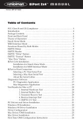
Break-Out Box Front Panel:<br />
1. Analog OUTS 1-4: These jacks output analog audio to a variety of external<br />
sources. Each jack is 1/4” TRS (Tip-Ring-Sleeve) and is compatible with 1/4”<br />
TRS (balanced) or TS (Tip-Sleeve unbalanced) connections.<br />
2. Analog INS 1-4: These jacks input analog audio from a variety of external<br />
sources. Each jack is 1/4” TRS (Tip-Ring-Sleeve) and is compatible with 1/4”<br />
TRS (balanced) or TS (Tip-sleeve unbalanced) connections.<br />
Break-Out Box Back Panel:<br />
3. Host Cable connector: This 15-pin D-sub connector is used to attach the<br />
external break-out box to the PCI host card, using the supplied host cable.<br />
PCI Host Adapter Card:<br />
4. Coaxial S/PDIF Input: This RCA connector receives an S/PDIF stereo signal<br />
from your coaxial S/PDIF digital source such as a DAT, MiniDisc player or<br />
external A/D converter.<br />
4
5. Coaxial S/PDIF Output: This RCA connector sends an S/PDIF stereo signal to<br />
your coaxial S/PDIF digital target device such as a DAT, MiniDisc player or<br />
external D/A converter.<br />
6. Host Cable connector: This 15-pin D-sub connector attaches to the supplied host<br />
cable to allow communication between the PCI host card and the break-out box.<br />
Quick <strong>Guide</strong> to Getting Started<br />
Here is a list of the steps required to get your <strong>Delta</strong> <strong>66</strong> up and running:<br />
1. Physically install the card in your computer and connect it to the <strong>Delta</strong> <strong>66</strong> breakout<br />
box (see ‘Hardware Installation’).<br />
2. Start Windows and allow Windows’ Plug-and-Play to prompt you for the<br />
<strong>Delta</strong> <strong>66</strong> drivers via the Add New Hardware wizard. Install drivers and support<br />
software (see ‘Windows Software Installation’).<br />
3. On the Mac, drag the <strong>Delta</strong> extension to the Extensions folder, and the<br />
appropriate ASIO driver to your application’s ASIO folder. Restart. If not using<br />
ASIO, set the Sound Manager to <strong>Delta</strong> (see Mac Installation).<br />
4. Configure your digital recording software to use the <strong>Delta</strong> <strong>66</strong> as its active audio<br />
device (see ‘Using the <strong>Delta</strong> <strong>66</strong> with your Software Application’ and also your<br />
software application’s manual).<br />
5. Hook up your digital and analog audio gear (see ‘<strong>Delta</strong> <strong>66</strong> Recording<br />
Tutorials’). Configure your <strong>Delta</strong> Control Panel software for proper monitoring<br />
and playback.<br />
Hardware Installation<br />
To mechanically install the <strong>Delta</strong> <strong>66</strong>, do the following:<br />
1. Turn off your computer.<br />
2. Remove the computer’s cover and position the computer so that you may easily<br />
access its PCI slots.<br />
3. Select the PCI slot where you will install your <strong>Delta</strong> <strong>66</strong> PCI host card. Make<br />
sure the slot is a PCI slot. If you don’t know what “PCI slot” means, check the<br />
owner’s manual for your computer. PCI slots are distinguishable from ISA slots<br />
by being shorter and set back farther from the outside of the computer, however<br />
some newer computers have only PCI slots.<br />
4. Before removing the <strong>Delta</strong> <strong>66</strong> PCI host card from its protective anti-static bag,<br />
touch the metal power supply case of the computer in order to dissipate any<br />
static electricity your body may have accumulated. You might want to pick up<br />
a grounding wrist strap (available from electronics stores like Radio Shack) if<br />
you want to be doubly sure you aren’t carrying a static charge that could damage<br />
5
the card.<br />
5. Remove the metal bracket that covers the access hole on the back of the<br />
computer. This bracket is usually fastened to the computer with a single screw.<br />
6. Position the <strong>Delta</strong> <strong>66</strong> PCI host card over the target PCI slot and fit the card<br />
loosely over it with the card in the upright position. Press the card gently but<br />
firmly downward into the slot until the card is completely and squarely seated<br />
in the slot. If the card seems difficult to seat, a slight rocking motion may help.<br />
7. Screw the <strong>Delta</strong> <strong>66</strong> PCI host card’s metal bracket down into the screw hole on<br />
the back of your computer using the screw you removed in step 5 above.<br />
8. Place the cover back on your computer.<br />
Now it is time to connect the <strong>Delta</strong> <strong>66</strong> break-out box to the PCI host card that you<br />
have just installed. Never attach the break-out box with the computer turned on.<br />
Doing so could damage the PCI card, and void your warranty. With your computer<br />
turned off:<br />
1. Place the <strong>Delta</strong> <strong>66</strong> break-out box on a desktop in a convenient but secure place,<br />
or mount the unit in a 19” rack-mount chassis. Rack mounting may be<br />
accomplished with a universal rack-mount tray, using a 5mm screw through the<br />
tray and into the mounting hole on the bottom of the <strong>Delta</strong> <strong>66</strong> break-out box.<br />
2. Connect one end of the supplied host cable to the 15-pin D-sub connector on the<br />
break-out box.<br />
3. Connect the other end of the host cable to the 15-pin D-sub connector on the<br />
<strong>Delta</strong> <strong>66</strong> PCI Host card that now resides in your computer.<br />
<strong>Delta</strong> Driver & Software Installation<br />
The <strong>Delta</strong> <strong>66</strong> system includes a “Drivers CD” for Windows 98/95/NT and<br />
Macintosh, containing all Windows drivers, Macintosh drivers (including all ASIO<br />
drivers), and <strong>Delta</strong> Control Panel software. To install these on your system, please<br />
follow these steps:<br />
Windows 98 Installation<br />
1. After installing the <strong>Delta</strong> <strong>66</strong> hardware, boot your system and start Windows.<br />
During the Windows boot procedure, the new hardware will be automatically<br />
detected by the ‘Add New Hardware Wizard’, as shown here. Click ‘Next>’.<br />
6
2. The ‘Add New Hardware Wizard’ will now ask how to locate the driver.<br />
“Search for the best driver for your device” is already selected. Click ‘Next>’.<br />
3. Windows will give you a selection of locations to search. Make sure that only<br />
“Choose a Path” is checked, or click on the check box to do so. Insert the<br />
Drivers CD into your CD ROM drive. Type in the drive letter of your CD drive<br />
(we will assume here that it is D:\) and the path to the <strong>Delta</strong> drivers, which will<br />
be D:\<strong>Delta</strong> Products\<strong>Delta</strong>98. Click ‘Next>’.<br />
4. The ‘Wizard’ reports that its Windows driver file search has found the M <strong>Audio</strong><br />
<strong>Delta</strong> <strong>66</strong>. Click ‘Next>’.<br />
5. Windows is now ready to install the driver files from the specified location.<br />
Click ‘Next>’. Windows will start to copy the files and show you a progress<br />
report screen.<br />
6. The Wizard reports that Windows has finished installing the software. Click<br />
‘Finish’. Your <strong>Delta</strong> <strong>66</strong> is ready for action.<br />
After completion of the driver installation, Windows may require you to restart<br />
Windows. If it does request a restart, remove the Drivers CD from the CD drive and<br />
respond by clicking “Yes”. The system will restart and your <strong>Delta</strong> <strong>66</strong> is ready for<br />
play.<br />
Windows 95 Installation<br />
1. After installation of the <strong>Delta</strong> <strong>66</strong> hardware, boot your system and start<br />
Windows. During the Windows boot procedure, new hardware will be<br />
automatically detected.<br />
2. Choose the Install of “driver from disk provided by hardware manufacturer,”<br />
then click OK.<br />
3. An ‘Install From Disk’ dialog will prompt you to copy files from the A:\ drive.<br />
Insert the Driver software CD into your CD ROM drive. Type in the drive letter<br />
of your CD drive (we will assume here that it is D:\) and the path to the <strong>Delta</strong><br />
drivers, which will be D:\<strong>Delta</strong> Products\<strong>Delta</strong>98 (these drivers also work in<br />
7
Win95). Click ‘Next>’.<br />
4. Windows will start to copy files, with a progress indicator on the screen. Once<br />
this process completes itself, your <strong>Delta</strong> <strong>66</strong> will be ready for action.<br />
After completion of the driver installation, Windows may require you to restart<br />
Windows. If it does request a restart, remove the Drivers CD from the CD drive and<br />
respond by clicking “Yes”. The system will restart and your <strong>Delta</strong> <strong>66</strong> is ready for<br />
play.<br />
Windows NT Installation<br />
1. Power up your computer after physically installing the <strong>Delta</strong> <strong>66</strong> card.<br />
2. Go to Start | Settings | Control Panel and double click on ‘Multimedia.’ Click<br />
the ‘Devices’ tab, then click the ‘Add’ button.<br />
3. “Unlisted or Updated Driver” will be highlighted at the top of the list. Click<br />
OK.<br />
4. The ‘Install Driver’ box will prompt you to insert the driver disk, and the A:<br />
prompt will appear as the path. Insert the Drivers CD into your CD ROM drive.<br />
Type in the drive letter of your CD drive (we will assume here that it is D:\) and<br />
the path to the <strong>Delta</strong> drivers, which will be D:\<strong>Delta</strong> Products\<strong>Delta</strong>NT. Click<br />
OK.<br />
5. The “M <strong>Audio</strong> <strong>Delta</strong> Interface Card” driver will appear in the Add Unlisted or<br />
Updated Driver dialog box. Click OK.<br />
6. Windows NT will require you to restart your computer for the changes to take<br />
effect. Choose “Restart Now.” Upon restart, your <strong>Delta</strong> <strong>66</strong> will be ready for<br />
use.<br />
Macintosh Installation<br />
1. Open the System folder on your Macintosh hard drive. In the System folder,<br />
locate the Extensions folder.<br />
2. On you Drivers CD disk, open the <strong>Delta</strong> Products folder, then the <strong>Delta</strong> <strong>66</strong><br />
folder. Place the extension file "<strong>Delta</strong> <strong>66</strong> Driver" in your Extensions folder by<br />
clicking on it and dragging it to the Extensions folder.<br />
3. If you are using a music program that uses ASIO drivers, it will also have an<br />
ASIO folder within the application’s folder. In your Mac <strong>Delta</strong> Drivers folder<br />
you will find three <strong>Delta</strong> <strong>66</strong> ASIO drivers. For Cubase versions 4.x, use the<br />
"ASIO2 <strong>Delta</strong><strong>66</strong>" driver. For Metro, or earlier versions of Cubase, use the<br />
"ASIO <strong>Delta</strong><strong>66</strong>v3" driver. For any music program that is not ASIO2 capable,<br />
use the “ASIO <strong>Delta</strong> <strong>66</strong>” driver instead (check your program’s documentation).<br />
Place the file "ASIO <strong>Delta</strong>" in your program's ASIO folder by clicking on it and<br />
dragging it to the ASIO folder.<br />
4. Drag the "<strong>Delta</strong>Panel PPC" file onto your Macintosh hard drive. You can run<br />
the <strong>Delta</strong> Control Panel from any place that's convenient, though music software<br />
applications that use ASIO will allow you to launch the <strong>Delta</strong> panel from within<br />
the program. If not, we suggest creating a alias to the control panel by<br />
8
highlighting it and pressing Command (Apple key)+M. Then, drag the alias to<br />
the desktop.<br />
5. With the <strong>Delta</strong> <strong>66</strong> PCI card installed, restarting the computer will load the <strong>Delta</strong><br />
<strong>66</strong> extension. You will be able to visually see the <strong>Delta</strong> extension icon pass by<br />
as your system loads extension.<br />
6. Go to the Apple menu |Control Panel | Sound. You should see the “built-in”<br />
sound icon, plus the <strong>Delta</strong> icon if your <strong>Delta</strong> <strong>66</strong> is properly installed. If your<br />
music program does use ASIO, leave the Sound Manager driver set to "built-in"<br />
for both Sound In and Sound Out. If your program does not use ASIO (check<br />
your software’s documentation) and you will be using the Sound Manager to<br />
communicate with your <strong>Delta</strong> <strong>66</strong>, set Sound In and Sound Out to “<strong>Delta</strong>.” See<br />
the section “Hardware Settings Page” in the <strong>Delta</strong> <strong>66</strong> “Control Panel Software”<br />
section for information on selecting Sound Manger inputs and outputs. Your<br />
<strong>Delta</strong> <strong>66</strong> is now ready for use.<br />
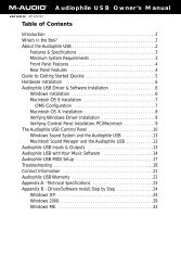
Verifying Windows Driver Installation<br />
Windows displays the <strong>Delta</strong> <strong>66</strong> driver status in the Device Manager page of the<br />
System Properties dialog box. The Device Manager page is opened via the Windows<br />
Start button: select Start | Settings | Control Panel | System | Device Manager. With<br />
the Device Manager displayed, click on the ‘+’ next to “Sound, video and game<br />
controllers” to open a list of devices, the <strong>Delta</strong> <strong>66</strong> being a device of that nature.<br />
Below is an example view of the Device Manager.<br />
9
This example shows the M <strong>Audio</strong> <strong>Delta</strong> <strong>66</strong> and Midiman WINMAN 4x4/S (another<br />
product shown here only as an example) entries in the Windows Device Manager<br />
device list. The <strong>Delta</strong> <strong>66</strong> is properly installed with no conflicts, as is the WINMAN<br />
4x4/S. If you do not see your M <strong>Audio</strong> <strong>Delta</strong> <strong>66</strong> in your Device Manager in this<br />
fashion, please jump ahead to the “Troubleshooting” section of this manual.<br />
Verifying <strong>Delta</strong> Control Panel Installation, PC & Mac<br />
In Windows, open the Windows Control Panel (do so via Start | Settings | Control<br />
Panel ). If your <strong>Delta</strong> <strong>66</strong> hardware and <strong>Delta</strong> Control Panel software are properly<br />
installed, the Windows Control Panel should display an “M <strong>Audio</strong> <strong>Delta</strong> H/W” icon.<br />
By double-clicking on that icon, you may launch the <strong>Delta</strong> Control Panel software.<br />
Also for convenience, you may create a shortcut on your desktop by dragging a copy<br />
of the “M <strong>Audio</strong> <strong>Delta</strong> H/W” icon from the Control Panel to your Windows desktop<br />
using your mouse or trackball. After completing the drag operation, a dialog box<br />
will ask you if you wish to create a shortcut — click on ‘Yes’. Once the shortcut is<br />
installed, all you have to do is double-click on the shortcut icon on your desktop to<br />
launch the <strong>Delta</strong> Control Panel software.<br />
On the Macintosh, the <strong>Delta</strong> Control Panel may be placed anywhere on your hard<br />
drive, or any partition of your hard drive that you find convenient. Once the control<br />
panel file has been dragged from the CD onto your hard drive, you may double click<br />
it to launch the <strong>Delta</strong> Control Panel software. You may create a alias to the control<br />
panel by highlighting it, then holding Apple key+M. This alias can then be placed<br />
on your desktop.<br />
NOTE: When using a music software program that is ASIO<br />
capable, launch the <strong>Delta</strong> Control Panel software from within<br />
that program. Some of the control panel functions will be<br />
controlled from within that program, such as master clock<br />
setting and sample rate, so it is desireable to launch the music<br />
program first, and then the <strong>Delta</strong> Control Panel from the the<br />
program’s “launch” or “control panel” button. Without the<br />
music program open however, it is okay to open the <strong>Delta</strong> panel<br />
from your desktop or other location.<br />
<strong>Delta</strong> System Overview<br />
<strong>Delta</strong>’s Analog Input/Outputs<br />
The <strong>Delta</strong> <strong>66</strong> Digital Recording Interface’s analog inputs and outputs are compatible<br />
with a wide variety of audio products. The <strong>Delta</strong> Control Panel software allows you<br />
to configure the signal level of each analog input individually, and all analog outputs<br />
as a group. Signal level settings of +4/Consumer/-10 are available. Selecting the<br />
‘+4’ radio button configures the channel(s) for use with +4dBu signal levels,<br />
compatible with most musical instruments and professional mixers. Selecting the<br />
10
‘–10’ setting sets up the channel(s) for -10dBV nominal signal levels, commonly<br />
used with consumer equipment such as CD, MiniDisc, cassette tape and DAT<br />
players. The ‘Consumer’ setting is preferred for semi-pro audio equipment and<br />
some consumer equipment that is too ‘hot’ for the ‘-10’ setting. The ‘Consumer’<br />
setting offers approximately 6dB more headroom than does the ‘-10’ setting. Semipro<br />
and consumer devices’ signal levels vary from manufacturer-to-manufacturer<br />
and even product-to-product, so a little experimentation between Consumer and –10<br />
settings may be required for optimal results.<br />
NOTE: In order to preserve its high dynamic range and<br />
minimize distortion, the <strong>Delta</strong> <strong>66</strong> does not have microphone<br />
pre-amplifiers built into it. Therefore direct connection to a<br />
microphone is not recommended. Instead run the microphone<br />
signal through a microphone pre-amp (such as the Midiman<br />
"<strong>Audio</strong> Buddy") and then connect the pre-amp output to the<br />
input of the <strong>Delta</strong> <strong>66</strong>.<br />
All analog jacks on the <strong>Delta</strong> <strong>66</strong> break-out box are of the 1/4” TRS (Tip-Ring-<br />
Sleeve) variety. The TRS jacks allow connection to either balanced (typically<br />
professional) or unbalanced (typically consumer or semi-pro) equipment. +4dBu<br />
balanced configurations provide the highest performance and should be used<br />
whenever possible. However, the <strong>Delta</strong> <strong>66</strong>’s analog connections support<br />
combinations of balanced and unbalanced, +4dBu, consumer, and –10dBV level<br />
signals.<br />
The Digital Monitor Mixer<br />
The <strong>Delta</strong> <strong>66</strong> Digital Recording System has a hardware digital audio mixer built into<br />
its PCI controller chip. It accepts digital audio streams from all hardware inputs and<br />
all outgoing software audio devices, mixes them with 36-bit internal precision and<br />
then provides the mixed output to one or more locations. For the purpose of<br />
monitoring, the output of the mixer may be routed to the first set of <strong>Delta</strong> <strong>66</strong> analog<br />
outputs (H/W OUT1/OUT2 as a stereo pair) and/or the S/PDIF digital output. At the<br />
same time the mixer may be used for stereo mix-down, with the mixer’s output<br />
recorded into the user’s application software. The digital audio mixer is configured<br />
and controlled by the included <strong>Delta</strong> Control Panel Software.<br />
The Patchbay / Router<br />
In addition to the built-in monitor mixer, the <strong>Delta</strong> <strong>66</strong> Digital Recording Interface<br />
includes an output patchbay/router. The patchbay/router allows each output (analog<br />
or digital) to be connected to a variety of input sources. The <strong>Delta</strong> <strong>66</strong>’s outputs may<br />
accept audio from software sources (the output devices visible in your audio<br />
software applications) or from hardware sources such as the analog and digital<br />
inputs or the monitor mixer. This capability makes the <strong>Delta</strong> <strong>66</strong> quite flexible for<br />
WAV output, monitoring, or directly connecting inputs to outputs for “system test”<br />
purposes.<br />
11
Synchronization<br />
For proper operation, the entire <strong>Delta</strong> <strong>66</strong> system is always synchronized to a single<br />
master clock. The master clock is chosen via the <strong>Delta</strong> Control Panel software and<br />
this clock may be derived from either the <strong>Delta</strong> <strong>66</strong>’s internal crystal oscillators or<br />
S/PDIF In. Most of the time the master clock is taken from the internal crystal<br />
oscillators. However, the S/PDIF option is used in situations where the <strong>Delta</strong> <strong>66</strong><br />
must be synchronized to external digital audio or sample rates.<br />
As stated, most of the time the master clock is derived from the internal crystal<br />
oscillators. Operation in this mode is similar to that of a generic sound card — for<br />
instance, when a WAV file is played through the <strong>Delta</strong> drivers, the software<br />
application playing the WAV file is responsible for setting the sample rate in the<br />
sound card hardware. The <strong>Delta</strong> <strong>66</strong> supports these sample rates by using either of<br />
its internal crystal oscillators and dividing the rate of that oscillator by some value<br />
to derive the proper sample rate.<br />
In situations where S/PDIF In is being used, the <strong>Delta</strong> <strong>66</strong> should be configured to get<br />
its master clock from the S/PDIF In data stream. The reason for this is simple —<br />
even if the sample rates are set the same, an S/PDIF data stream coming from an<br />
external source is rarely going to be in sync with the <strong>Delta</strong> <strong>66</strong> (or other digital audio<br />
devices in the system for that matter). If the master clock were set to use the internal<br />
crystal, then the incoming S/PDIF audio would have “pops,” “crackles,” and other<br />
undesirable audio artifacts present in it. Instead, setting the master clock to “S/PDIF<br />
In” will synchronize the <strong>Delta</strong> <strong>66</strong> to the S/PDIF input data and its digital audio will<br />
be transferred properly.<br />
Finally, the S/PDIF In option may be used to operate the <strong>Delta</strong> <strong>66</strong> at non-standard<br />
sample rates. When this option is selected, the <strong>Delta</strong> <strong>66</strong>’s sample rate will<br />
automatically match that of the incoming S/PDIF data stream.<br />
NOTE: When the S/PDIF In is selected as the master clock<br />
source, the <strong>Delta</strong> <strong>66</strong> mixer’s frequency response will be affected<br />
by whatever sample rates you inject at the S/PDIF In. This is<br />
because (1) the digital mixer operates at the same sample rate<br />
as the rest of the board, and (2) sample rate and frequency<br />
response are directly correlated.<br />
Using the <strong>Delta</strong> <strong>66</strong> with your Software Application<br />
Once the <strong>Delta</strong> <strong>66</strong>’s hardware and driver software are properly installed, it is ready<br />
for use with your music application software. Some of these applications may<br />
require you to highlight or enable the <strong>Delta</strong> <strong>66</strong> drivers within the program, and others<br />
may have a utility that analyzes or profiles the audio cards in your system and<br />
enables the drivers. Your software should have an audio device driver setup page.<br />
WINDOWS MME AUDIO INPUT DEVICES: All <strong>Delta</strong> <strong>66</strong> analog and S/PDIF<br />
inputs may be used simultaneously for a total of 6 input channels. Within your<br />
software application(s), the names of the <strong>Delta</strong> <strong>66</strong> audio input devices are:<br />
12
PCM In 1/2 <strong>Delta</strong>-<strong>66</strong><br />
PCM In 3/4 <strong>Delta</strong>-<strong>66</strong><br />
S/PDIF In <strong>Delta</strong>-<strong>66</strong><br />
Mon.Mixer <strong>Delta</strong>-<strong>66</strong><br />
The PCM In devices allow recording a stereo stream directly from the specified<br />
analog input pairs. The S/PDIF In device allows you to record a stereo stream<br />
directly from the S/PDIF input. The Mon.Mixer device allows stereo recording from<br />
the digital “monitor” mixer built-into the <strong>Delta</strong> <strong>66</strong>. The audio data recorded from<br />
this device is the mix of input and output streams set up in the <strong>Delta</strong> Control Panel<br />
software (see <strong>Delta</strong> <strong>66</strong> Control Panel Software section).<br />
Note that all of the input devices are stereo. Your application<br />
software may break these down further to “left” and “right”<br />
mono devices. Therefore you may see them as “Left PCM In 1/2<br />
<strong>Delta</strong>-<strong>66</strong>, Right PCM In 1/2 <strong>Delta</strong>-<strong>66</strong>”, “Left S/PDIF In <strong>Delta</strong>-<strong>66</strong>,<br />
Right S/PDIF In <strong>Delta</strong>-<strong>66</strong>”, or “Left Mon. Mixer <strong>Delta</strong>-<strong>66</strong>, Right<br />
Mon. Mixer <strong>Delta</strong>-<strong>66</strong>,” etc. from within your recording software.<br />
WINDOWS MME AUDIO OUTPUT DEVICES: All <strong>Delta</strong> <strong>66</strong> analog and S/PDIF<br />
outputs may be used simultaneously for a total of 6 output channels. Within your<br />
software application(s), the names of the <strong>Delta</strong> <strong>66</strong> audio output devices are:<br />
WavOut 1/2 <strong>Delta</strong>-<strong>66</strong><br />
WavOut 3/4 <strong>Delta</strong>-<strong>66</strong><br />
WavOut S/PDIF <strong>Delta</strong>-<strong>66</strong><br />
WavOut devices allow playing a stereo audio stream to the analog hardware outputs<br />
(for WavOut 1/2, 3/4), the S/PDIF hardware output (for WavOut S/PDIF), or into the<br />
hardware router or mixer. Your application software may break each of these stereo<br />
devices down further to “left” and “right” mono devices. Therefore you may see<br />
them as “Left WavOut 1/2 <strong>Delta</strong>-<strong>66</strong>, Right WavOut 1/2 <strong>Delta</strong>-<strong>66</strong>”, or “Left WavOut<br />
S/PDIF <strong>Delta</strong>-<strong>66</strong>, Right WavOut S/PDIF <strong>Delta</strong>-<strong>66</strong>”, etc. from within your music<br />
software. Most software will handle the outputs as stereo pairs but allow you to pan<br />
audio left or right within the pair. Therefore to send a mono output to OUT1 (for<br />
example), choose WavOut 1/2, then pan that track hard left.<br />
Note that each device name begins with “WavOut.” This is to<br />
remind you that these are software devices, and not always<br />
connected directly to output hardware. Instead they are<br />
connected to the <strong>Delta</strong> <strong>66</strong>’s internal patchbay/router and may<br />
be sent to one of several destinations. For more on the<br />
patchbay/router, see the Patchbay/Router section of the <strong>Delta</strong><br />
Control Panel software discussion.<br />
MACINTOSH SOUND MANAGER INPUTS AND OUTPUTS: The Apple Sound<br />
Manager limits the user to one stereo pair for input and one stereo pair for output.<br />
Within your music software, the device selection when using the Sound Manager<br />
13
drivers for input and output will be “Sound Manager” both for input source and for<br />
output port.<br />
To select the Sound Manager driver, open the Apple Menu and go to Control Panel<br />
| Sound. For both “Sound In”and “Sound Out,” click and highlight the <strong>Delta</strong> icon,<br />
then exit. You may select which <strong>Delta</strong> hardware stereo input pair and stereo output<br />
pair will be used for the Sound Manager’s Sound In and Sound Out in the <strong>Delta</strong><br />
Control Panel “Hardware Settings Page” (see section, “Hardware Settings<br />
Page”under “<strong>Delta</strong> Control Panel”). Whichever stereo pair you select, the software<br />
input and output device selection within your music program will remain the same.<br />
ASIO DRIVER INPUT DEVICES: When using the ASIO audio drivers with<br />
programs that support ASIO-style audio, the input devices are displayed as mono<br />
devices. Within ASIO software applications, the names of the <strong>Delta</strong> <strong>66</strong> audio input<br />
devices are:<br />
Analog In1 <strong>Delta</strong>-<strong>66</strong><br />
Analog In2 <strong>Delta</strong>-<strong>66</strong><br />
Analog In3 <strong>Delta</strong>-<strong>66</strong><br />
Analog In4 <strong>Delta</strong>-<strong>66</strong><br />
S/PDIF In L <strong>Delta</strong>-<strong>66</strong><br />
S/PDIF In R <strong>Delta</strong>-<strong>66</strong><br />
Mon.Mixer L <strong>Delta</strong>-<strong>66</strong><br />
Mon.Mixer R <strong>Delta</strong>-<strong>66</strong><br />
Notice the S/PDIF In and Monitor Mixer names include “L” and “R” characters.<br />
“L” indicates the left channel of the stereo stream, while “R” indicates right channel.<br />
ASIO DRIVER OUTPUT DEVICES: The <strong>Delta</strong> <strong>66</strong>’s ASIO output devices appear in<br />
stereo pairs. Because each device is stereo, you may see “left” and “right”<br />
references within your software application. This allows the application to pan<br />
audio left and right under software control. To send a signal to a <strong>Delta</strong> ASIO output<br />
1 (for example) as a mono output send, one would choose “Analog 1/2 <strong>Delta</strong>-<strong>66</strong>” for<br />
that track’s output port, and then pan that output hard left. The ASIO outputs are<br />
named as follows:<br />
Analog 1/2 <strong>Delta</strong>-<strong>66</strong><br />
Analog 3/4 <strong>Delta</strong>-<strong>66</strong><br />
S/PDIF L/R <strong>Delta</strong>-<strong>66</strong><br />
WINDOWS MULTIMEDIA SETTINGS: Windows may be set up to use the<br />
<strong>Delta</strong> <strong>66</strong> as its default audio device, allowing system sounds to be sent out the <strong>Delta</strong><br />
<strong>66</strong>. This also enables you to use the <strong>Delta</strong> <strong>66</strong> with the sound applets included with<br />
Windows. To set this up, go to Control Panel | Multimedia. In the <strong>Audio</strong> Properties<br />
page, set the Playback and Recording devices to the <strong>Delta</strong> <strong>66</strong> input and output<br />
devices of your choice.<br />
14
<strong>Delta</strong> <strong>66</strong> Control Panel Software<br />
ON THE PC: Once the <strong>Delta</strong> <strong>66</strong> is properly installed, an "M <strong>Audio</strong> <strong>Delta</strong> H/W" icon<br />
will be displayed in your Windows Control Panel. By double-clicking on that icon,<br />
you will launch the <strong>Delta</strong> Control Panel software. You may also launch the <strong>Delta</strong><br />
Control Panel software from the desktop if you have previously created a shortcut<br />
there (see "Verifying <strong>Delta</strong> Control Panel Software Installation" section for<br />
instructions on how to do this). Once the <strong>Delta</strong> Control Panel software has been<br />
opened, you will see the main panel and its several tabs. To display a desired page,<br />
click on its tab. Below are functional descriptions of each page.<br />
ON THE MAC: The <strong>Delta</strong> Control Panel must be placed on the hard drive by<br />
dragging the application from the Drivers CD. Once this is done, a alias may be<br />
created by highlighting the <strong>Delta</strong> Control Panel on the hard drive and pressing the<br />
Apple key+M. Then, this alias may be dragged to the desktop. Double clicking<br />
either will launch the control panel. Once the <strong>Delta</strong> Control Panel software has been<br />
opened, you will see the main panel and its several tabs. To display a desired page,<br />
click on its tab. Below are functional descriptions of each page. Though most of the<br />
desciptions are Windows based, the functions are identical unless otherwise<br />
indicated. Within each section you will find the necessary name changes for using<br />
the <strong>Delta</strong> Control Panel “ON THE MAC.”<br />
NOTE: When using a music software program that is ASIO<br />
capable, launch the <strong>Delta</strong> Control Panel software from within<br />
that program. There will be a button in the ASIO or <strong>Audio</strong> setup<br />
page that will allow you to do so. Some of the control panel<br />
functions will be controlled from within that program, such as<br />
master clock setting and sample rate, so it is desireable to<br />
launch the music program first, and then the <strong>Delta</strong> Control<br />
Panel from the the program’s “launch” or “control panel”<br />
button. Without the music program open however, it is okay to<br />
open the <strong>Delta</strong> panel from your desktop or other location.<br />
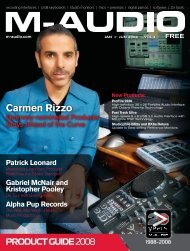
Monitor Mixer Page<br />
The Monitor Mixer is the first page that appears when the <strong>Delta</strong> Control Panel is<br />
opened, and controls the digital mixer built into the <strong>Delta</strong> <strong>66</strong>’s PCI controller chip.<br />
As described in previous sections, the output of this mixer may be assigned to the<br />
OUT1/OUT2 analog outputs and/or the S/PDIF Out digital output. At the same<br />
time, the mixer outputs may be recorded in stereo by software.<br />
15
The Monitor Mixer Page is essentially a collection of volume level faders, audio<br />
level (or ‘peak’) meters, and solo/mute controls. For each mixer output and input<br />
channel there is one of each: a volume fader, a peak meter, a solo control, and a mute<br />
control.<br />
LEVEL FADERS: Each volume fader may be controlled by dragging its fader<br />
‘handle’ vertically with the mouse, or by clicking on the ‘handle’ to make it active<br />
and then adjusting it with the up/down cursor keys of your computer keyboard.<br />
Because the mixer has no gain, these faders only attenuate (reduce) the signal levels.<br />
The highest setting is 0dB, or ‘Unity Gain.’ The default fader setting is the quietest<br />
setting, –144dB, which essentially mutes the audio. A pair of level faders may be<br />
“ganged” so that both channels may be adjusted together as a stereo pair.<br />
Also, at the top of each fader and meter is a fader level “fine adjustment” control.<br />
Clicking on the small “up” and “down” arrows will adjust the corresponding fader<br />
setting in 0.5dB increments. Next to each fine adjustment control is a numerical<br />
fader readout that is always current and active.<br />
PEAK METERS: Each peak meter indicates an audio signal level in “dB relative to<br />
full-scale.” This means that a full-scale signal is referred to as “0 dB” and a signal<br />
that is 12dB ‘quieter’ than full-scale is referred to as “-12dB.” The meters are<br />
vertically color-coded into three sections: green, yellow and red. The green section<br />
represents a safe zone, ranging from approximately -48dB to -12dB. Most audio<br />
signals should appropriately fill this section of the meter. The yellow section ranges<br />
from -12dB to -3dB as the signal approaches a ‘hotter’ level. For best capture<br />
resolution, recording in this area is both safe and advised. The red section of the<br />
meter ranges from -3dB to 0dB. On the input level meters, a 0dB condition indicates<br />
16
overload and audio clipping may occur. Therefore be careful to adjust the incoming<br />
audio levels so that they do not peak in the red section too long (you might use the<br />
monitoring capability of the <strong>Delta</strong> <strong>66</strong> to let your ears be the judge). On all output<br />
level meters, 0dB indicates full-scale output. Unlike the inputs, hardware clipping<br />
is impossible on the outputs because of the 36-bit resolution built into the mixer<br />
hardware. However, please note that it is possible to mix multiple tracks within your<br />
software application and cause clipping to occur in the output stream before it<br />
reaches the <strong>Delta</strong> output hardware or monitor mixer.<br />
MASTER VOLUME: At the left side of the Monitor Mixer page, you will see the<br />
‘Master Volume’ faders and peak meters. These faders have the longest ‘throw’ and<br />
highest meter resolution of any level controls in the mixer page. They control the<br />
overall stereo level of the mixer output. The peak meters indicate the output signal<br />
levels with respect to full-scale and are directly affected by the settings of the master<br />
volume faders.<br />
MIXER INPUTS: The ‘Mixer Inputs’ are inputs to the monitor mixer. These inputs<br />
accept hardware audio streams (directly from the <strong>Delta</strong>’s analog and digital input<br />
ports) and software audio streams (digital audio generated in software to be output).<br />
This combination of streams makes the monitor mixer extremely flexible. Each<br />
mixer input channel has its own level fader and may be panned anywhere in the<br />
left/right stereo field. Each input also has its own peak meter. The peak meters<br />
indicate the incoming “pre-fader” levels of the incoming audio and are therefore not<br />
affected by the fader settings. However, the input faders do affect the levels of the<br />
signals exiting the mixer and you will see the effect of the input faders on the output<br />
“Master Volume” peak meters.<br />
Because of the large number of mixer inputs, not all inputs are displayed<br />
simultaneously. You may use the scroll bar at the bottom of the <strong>Delta</strong> Control Panel<br />
to scroll the view left or right. From far left to right, the inputs are labeled “WavOut<br />
1/2,” “WavOut 3/4,” then “WavOut S/PDIF.” These inputs accept the digital audio<br />
streams being sent from your software application (or Windows) to the driver<br />
devices with those same names. Each name begins with “WavOut” to remind you<br />
that these are software streams and may not necessarily be routed to any physical<br />
outputs (see Patchbay/Router Page). Further to the right are more channels, labeled<br />
“H/W In S/PDIF,” “H/W In 1/2,” and “H/W In 3/4.” These mixer inputs are audio<br />
streams from the physical <strong>Delta</strong> <strong>66</strong> hardware inputs, hence the “H/W” at the front of<br />
each label. On the Mac, these inputs are labeled “SM/ASIO,” as these software<br />
streams will be receiving their digital audio either from the Sound Manager or the<br />
ASIO driver, depending on your selection.<br />
PAN: Each mixer input may be individually panned anywhere in the stereo output<br />
mix. A pan control is positioned directly under each input channel peak meter and<br />
has the appearance of a small vertical pointer. To make a coarse adjustment, click<br />
on the pan control with your mouse and drag it to the desired position. For finer<br />
17
adjustment (in 1% increments), you may click on the pan control to make it active,<br />
and then use the left/right or up/down cursor keys on your computer keyboard.<br />
Either way, while the pan setting is being adjusted, its value will appear numerically<br />
in the Master Volume’s status box (below the Master Volume Stereo Gang control)<br />
as a percentage from left pan to right pan: -100% represents far left, +100%<br />
represents far right, and 0% represents the center.<br />
SOLO: Each mixer input channel has a “Solo” checkbox associated with it.<br />
Clicking on and activating a Solo box will solo the selected channel by essentially<br />
muting all other signals. When more than one channel has Solo selected, all solo<br />
channels will be summed to the solo ‘buss’ (path), which is what one might consider<br />
an ‘in place’ solo as opposed to a PFL, or pre-fader listen (levels and pans still<br />
apply). Deactivating all solo boxes will return all input channels to their previous<br />
mute/unmute states.<br />
MUTE: Every mixer input channel has a “Mute” checkbox associated with it.<br />
Clicking on and activating the Mute box will remove that signal from the stereo<br />
buss. Deactivating the Mute box will add the signal back into the stereo buss.<br />
STEREO GANG: All input channel pairs have a “Stereo Gang” capability. Clicking<br />
on and activating the Stereo Gang checkbox will link (or “gang”) the left/right faders<br />
so that both channels may be adjusted together as a stereo pair.<br />
Patchbay/Router Page<br />
The Patchbay/Router page allows you to connect each of the <strong>Delta</strong> <strong>66</strong>’s hardware<br />
outputs (2 pairs of analog outputs and 1 pair of digital output channels) to specific<br />
audio sources within the <strong>Delta</strong> <strong>66</strong> board. To display this page, click the<br />
“Patchbay/Router” tab of the <strong>Delta</strong> Control Panel.<br />
ON THE MAC: Please substitute the name “SM/ASIO” where referrences are made<br />
to “WavOut.” SM/ASIO are the software outputs on the Mac, while WavOut are the<br />
software outputs on the PC. Substitute “Windows multimedia applet” with “Sound<br />
Manager Applet.”<br />
The leftmost vertical column of Patchbay/Router page, “H/W Out 1/2,” connects this<br />
hardware analog stereo pair to one of six stereo sources:<br />
1. The default setting, “WavOut 1/2”, connects ports OUT1 and OUT2 to your<br />
music software or Windows multimedia applet. In other words, when music<br />
software plays audio to the device named “WavOut 1/2 <strong>Delta</strong>-<strong>66</strong>” it will be<br />
routed directly to the “hardware” analog outputs 1 & 2 of your <strong>Delta</strong> <strong>66</strong>’s breakout<br />
box.<br />
2. The second option, “Monitor Mixer,” connects ports OUT1 and OUT2 to the<br />
outputs of the <strong>Delta</strong> <strong>66</strong> monitor mixer. For more information of the capabilities<br />
of the monitor mixer, please see the section “Monitor Mixer Page.”<br />
18
3. The third option, “S/PDIF In,” connects ports OUT1 and OUT2 directly to the<br />
hardware S/PDIF input on the <strong>Delta</strong> <strong>66</strong> PCI host card. The left channel of the<br />
S/PDIF In is routed to OUT1 and the right channel of the S/PDIF In is routed to<br />
OUT2.<br />
4. The fourth option, “S/PDIF In (L/R Rev.),” functions identically to the third<br />
option, except that the left and right channels are swapped. Therefore in this<br />
mode, the left channel of the S/PDIF In is routed to OUT2 and the right channel<br />
of the S/PDIF In is routed to OUT1. Note that this option is solely for<br />
monitoring/mixing purposes — the S/PDIF In will not record in reverse when<br />
this option is checked.<br />
5. Selections five and six connect the hardware analog inputs 1 & 2 or 3 & 4<br />
(respectively) directly to the <strong>Delta</strong> <strong>66</strong>’s hardware analog outputs 1 & 2. For<br />
example, if “H/W In 1/2” were selected, any signal present at the IN1 port will<br />
be copied to OUT1, and any signal present at the IN2 port will be copied to<br />
OUT2. This same behavior applies to “H/W In 3/4” when selected.<br />
The next vertical column of the Patchbay/Router page “H/W Out 3/4,” connect this<br />
hardware analog stereo pair to one of five stereo sources.<br />
1. The default setting, “WavOut 3/4”, connects ports OUT3 and OUT4 to your<br />
music software or Windows multimedia applet. In other words, when music<br />
software plays audio to the device named “WavOut 3/4 <strong>Delta</strong>-<strong>66</strong>” it will be<br />
routed directly to the “hardware” analog outputs 3 & 4 of your <strong>Delta</strong> <strong>66</strong>’s breakout<br />
box.<br />
2. The second option, “S/PDIF In”, connects ports OUT3 and OUT4 directly to the<br />
hardware S/PDIF input on the <strong>Delta</strong> <strong>66</strong> PCI host card. The left channel of the<br />
S/PDIF In is routed to OUT3 and the right channel of the S/PDIF In is routed to<br />
OUT4.<br />
3. The third option, “S/PDIF In (L/R Rev.)”, functions identically to the second<br />
option, except that the left and right channels are swapped. Therefore in this<br />
mode, the left channel of the S/PDIF In is routed to OUT4 and the right channel<br />
of the S/PDIF In is routed to OUT3.<br />
4. Options four and five connect the hardware analog inputs 1 & 2 or 3 & 4<br />
(respectively) directly to the <strong>Delta</strong> <strong>66</strong>’s hardware analog outputs 3 & 4. For<br />
example, if “H/W In 1/2” were selected, any signal present at the IN1 port will<br />
be copied to OUT3, and any signal present at the IN2 port will be copied to<br />
OUT4. This same behavior applies to “H/W In 3/4” when selected.<br />
The rightmost vertical column of Patchbay/Router page, “H/W Out S/PDIF,”<br />
connects the <strong>Delta</strong> <strong>66</strong>’s hardware S/PDIF output to one of six stereo sources:<br />
1. The default setting, “WavOut S/PDIF,” connects the S/PDIF Out port to<br />
your music software or Windows multimedia applet. In other words, when<br />
music software plays audio to the device named “WavOut S/PDIF <strong>Delta</strong>-<br />
<strong>66</strong>” it will be routed directly to the hardware S/PDIF output on your <strong>Delta</strong><br />
<strong>66</strong>’s PCI host card.<br />
19
2. The second option, “Monitor Mixer,” connects the S/PDIF Out port to the<br />
outputs of the <strong>Delta</strong> <strong>66</strong> monitor mixer. For more information on the capabilities<br />
of the monitor mixer, please see the section “Monitor Mixer Page.”<br />
3. The third option, “S/PDIF In,” connects the S/PDIF Out port directly to the<br />
hardware S/PDIF input on the <strong>Delta</strong> <strong>66</strong> PCI host card. The left channel of the<br />
S/PDIF In is routed to the left channel of S/PDIF Out and the right channel of<br />
the S/PDIF In is routed to the right channel of S/PDIF Out.<br />
4. The fourth option, “S/PDIF In (L/R Rev.),” functions identically to the third<br />
option, except that the left and right channels are swapped. Therefore in this<br />
mode, the left channel of the S/PDIF In is routed to the right channel of S/PDIF<br />
Out and the right channel of the S/PDIF In is routed to the left channel of<br />
S/PDIF Out.<br />
5. Selections five and six connect the hardware analog inputs 1 & 2 or 3 & 4<br />
(respectively) directly to the <strong>Delta</strong> <strong>66</strong>’s S/PDIF Out port. For example, if “H/W<br />
In 1/2” were selected, any signal present at the IN1 port will be sent to the left<br />
channel of the S/PDIF Out, and any signal present at the IN2 port will be sent<br />
to the right channel of the S/PDIF Out. This same behavior applies to “H/W In<br />
3/4” when selected.<br />
At this point, you may begin to realize the versatility of the Monitor Mixer and the<br />
Patchbay/Router, and the relationship between the two. You may want to re-read this<br />
section and make some practice adjustments within the <strong>Delta</strong> Control Panel software<br />
to become proficient in routing and mixing. If somewhere in the process you<br />
become confused, you may always restore the default settings to use the card as a<br />
straight 6-in 6-out device — just choose the topmost option in each of the<br />
Patchbay/Router columns.<br />
Hardware Settings Page<br />
The Hardware Settings page of the <strong>Delta</strong> Control Panel gives you control over<br />
miscellaneous features of the <strong>Delta</strong> <strong>66</strong>. To display this page, click the “Hardware<br />
Settings” tab of the <strong>Delta</strong> Control Panel.<br />
MASTER CLOCK: This section allows you to select the source of the board’s<br />
master clock: Internal Xtal (crystal) or S/PDIF In. Master clock operation is outlined<br />
in the Synchronization section of this manual. Internal Xtal is the default setting. Be<br />
sure to select “S/PDIF In” if you will be recording or monitoring an S/PDIF stream.<br />
NOTE: If “S/PDIF In” is selected as the master clock source, be<br />
sure to supply a valid S/PDIF signal to the board’s active S/PDIF<br />
input. Otherwise, erratic timing and/or improper sample rates<br />
will be experienced.<br />
20
Once a master clock source has been selected, its synchronization status is<br />
continually monitored and displayed below the master clock radio buttons. If<br />
internal crystal is selected, the status display will always say “Locked.” On the other<br />
hand, if S/PDIF In is selected as the master clock source, the control panel will<br />
display “Locked” only when a valid S/PDIF signal is detected. It will display<br />
“Unlocked” when there is no signal at the S/PDIF input, or when the signal is corrupt<br />
or invalid for any reason.<br />
CODEC SAMPLE RATE: This section indicates the present board sample rate, as<br />
set by application software. The sample rate displayed here is used to drive the<br />
digital mixer and all outputs. The “Rate Locked” checkbox is used to force a sample<br />
rate upon the system. It is disabled by default to allow software access to all<br />
supported sample rates. When checked, it causes the driver to only operate at the<br />
selected sample rate. This means that any application that attempts to open the<br />
<strong>Delta</strong> <strong>66</strong> driver at a sample rate other than the one selected here will fail to do so and<br />
will post an error message. “Reset Rate When Idle” is selected when you want the<br />
sample rate to return to a particular setting when a software application is not<br />
actively using the board. This is particularly handy for keeping the digital mixer<br />
running at a specific sample rate.<br />
NOTE: Because the digital monitor mixer runs at the sample<br />
rate of the rest of the board, and because sample rate directly<br />
affects frequency response, it may sometimes be desirable to<br />
keep the sample rate at or above 44.1 kHz while using the<br />
monitor mixer. This is accomplished by enabling “Reset Rate<br />
When Idle” and selecting a sample rate of 44.1 kHz or greater.<br />
S/PDIF SAMPLE RATE: When using S/PDIF In as your master clock, this section<br />
tells the driver what the expected S/PDIF input sample rate is. The section is only<br />
displayed when the board is set to use S/PDIF In as the master clock source. From<br />
the list, select the sample rate closest to that of the S/PDIF input data. The sample<br />
rate selected here will be the only sample rate available to the software applications.<br />
Therefore, you must set your audio software application to this same sample rate or<br />
else the application will display an error message.<br />
NOTE: When S/PDIF In is the master clock source, the digital<br />
monitor mixer will run at the sample rate received at the S/PDIF<br />
In. Since frequency response and sample rate are directly<br />
related, the mixer frequency response will be directly related to<br />
the sample rate of the S/PDIF input data.<br />
MULTITRACK DRIVER DEVICES: The <strong>Delta</strong> <strong>66</strong> drivers may intelligently<br />
synchronize the beginning of recording and playback across all audio devices on the<br />
board. When using application software that is capable of using multiple channels<br />
simultaneously, select “Single and In-Sync” to ensure that all audio channels will<br />
21
egin playback and/or recording at the same time. Otherwise select “Independent”<br />
to allow the audio channels to play independently — this setting may be desirable if<br />
more than one application needs to access the <strong>Delta</strong> <strong>66</strong> simultaneously.<br />
DMA BUFFER SIZES: This section specifies the amount of system memory<br />
dedicated to digital audio buffering. Setting a buffer size that is too small may result<br />
in clicks or pops in the audio stream as some data may be lost. Larger buffers cause<br />
slightly more latency but prevent the pops and clicks that might occur with smaller<br />
buffer sizes — the default settings are recommended but you may desire to tweak<br />
these default settings to suit your tastes.<br />
ON THE MAC: The Hardware Settings Page in the Macintosh version of the <strong>Delta</strong><br />
Control Panel also contains software switches that allow you to select which <strong>Delta</strong><br />
input and output stereo pair will be used by the Sound Manager, if and when you<br />
choose the <strong>Delta</strong> as the Sound Manager input and output device. If you go to the<br />
Apple menu | Control Panel |Sound and highlight the <strong>Delta</strong> icon for Sound In and<br />
Sound Out, then your Apple system sounds will be routed to the <strong>Delta</strong> hardware<br />
output that you have selected here, and Alert Sounds, if you choose to record, will<br />
receive their input from the <strong>Delta</strong> hardware input that you select here.<br />
You will want to choose the <strong>Delta</strong> for input and output in the Sound control panel if<br />
your music program does not use ASIO and the <strong>Delta</strong> ASIO drivers. If you are using<br />
the ASIO drivers (see Mac Software Installation), then leave the Sound control panel<br />
selection to “built-in.” With the Sound control panel set to built-in, these Sound<br />
Manager settings in the <strong>Delta</strong> Control Panel will have no effect.<br />
The Sound Manager driver limits you to using only one of the <strong>Delta</strong> 1010 stereo<br />
input pairs for audio input and only one of the stereo output pairs for output. These<br />
do not need to be matched pairs- you can use inputs 1&2 for Sound In and S/PDIF<br />
for Sound Out, for example, or any combination that you choose. The following<br />
screen shot shows the Hardware Settings page on the Mac with the Sound Manager<br />
I/O set to “Analog 1&2” for Input and “Analog 1&2” for Output. Once you have<br />
made a selection, go to the File menu and “Save as Preferences.”<br />
22
VARIABLE SIGNAL LEVELS: The software switches in this section allow the user<br />
to match individual input levels and global (as in ‘all’ or ‘across the board’) output<br />
levels to the operating signal levels of the external audio equipment. Three level<br />
selections are available: +4dBu, ‘Consumer,’ and –10dBV. The ‘+4dBu’ setting is<br />
the least ‘sensitive’ of the three settings, and ‘–10dBV’ the most sensitive.<br />
Therefore, the ‘+4dBu’ setting has the most headroom and can accept the hottest<br />
signals of the three settings.<br />
Consult the user guide of your external audio equipment regarding your equipment’s<br />
line level. If for instance your audio equipment is consumer or semi-pro, and you<br />
find that its input level is a little too hot for the <strong>Delta</strong> <strong>66</strong>’s ‘-10dBV’ setting, try<br />
switching to the ‘Consumer’ setting. Conversely, if your –10dBV gear is receiving<br />
a signal from the <strong>Delta</strong> <strong>66</strong> that is too hot, try switching the <strong>Delta</strong> <strong>66</strong>’s output levels<br />
from ‘Consumer’ to the ‘–10dBV’ setting.<br />
S/PDIF Page<br />
The S/PDIF page of the <strong>Delta</strong> Control Panel configures the S/PDIF output format<br />
and displays the status of the S/PDIF input. To display this page, click the “S/PDIF”<br />
tab of the <strong>Delta</strong> Control Panel software.<br />
DIGITAL INPUT: This group box displays the current S/PDIF input status. The<br />
<strong>Delta</strong> <strong>66</strong>’s S/PDIF receiver is capable of recognizing a valid input signal versus an<br />
invalid, corrupt or non-present one. When a valid signal is detected at S/PDIF In,<br />
this group box displays “Valid Input Detected.” When an invalid signal is detected<br />
or no signal is present, the group box displays “Invalid or Not Present.” Below this<br />
23
message are two ‘grayed-out’ buttons: “Coax(RCA)” and “Optical.” These are<br />
functions of the <strong>Delta</strong> DiO 2496, another product in the M <strong>Audio</strong> <strong>Delta</strong> line, one with<br />
both optical and coaxial S/PDIF inputs. These controls do not apply to the <strong>Delta</strong> <strong>66</strong>.<br />
DIGITAL OUTPUT FORMAT: Within the “Digital Output Format” group, you<br />
choose the digital audio format of the S/PDIF output. The default setting,<br />
“Consumer,” is a true S/PDIF format and is recognized by all consumer devices.<br />
The alternate “Professional” setting is an AES/EBU type data stream, but electrically<br />
S/PDIF. This is a work-around that is recognized by some but not all AES/EBU<br />
devices.<br />
For both consumer and professional output formats, the “Advanced” checkbox will<br />
allow you to force a few particular status bits in the outgoing S/PDIF signal. The<br />
advanced option is for expert users only; however, if you decide to go exploring,<br />
change a few bit settings and get lost, you can always select the “Restore Defaults”<br />
button to restore the outgoing status bits to their factory settings. When “Consumer”<br />
and “Advanced” are both selected, the group “Consumer Format Advanced Settings”<br />
will appear. When “Professional” and “Advanced” are both selected, the group<br />
“Professional Format Advanced Settings” will appear. These groups are described<br />
below:<br />
Consumer Format Advanced Settings (Copy Mode): Copy protection, also known as<br />
Serial Copy Management System (SCMS), is written into the S/PDIF subcode, a<br />
reserved part of the S/PDIF digital stream that is independent of the actual audio data<br />
being transmitted. It can be used to inhibit the amount of copies that can be made,<br />
or allow for unlimited copying. Three SCMS modes are available. “Original (Copy<br />
Permitted)” indicates that the source material may be copied by a receiving device.<br />
“1st Generation” indicates that the source material is a first generation copy. Most<br />
devices that are capable of recording will reject material with this SCMS mode set.<br />
The final option is “No SCMS” which may be used to override the other two modes<br />
and allow a recording device to successfully record the audio data. Different<br />
manufacturers’ products may interpret these codes differently and require you to set<br />
these bits by “trial-and-error” until proper operation is achieved.<br />
Consumer Format Advanced Settings (Emphasis): This status bit is used to indicate<br />
if pre-emphasis has been applied to the outgoing digital audio signal. The default is<br />
“None” and rarely will any user want to set the value to “50/15uSec” unless the<br />
transmitted audio has been encoded with 50/15uSec pre-emphasis.<br />
Professional Format Advanced Settings (Data Type): The user may assign the<br />
outgoing data as audio or non-audio data. Many devices ignore this setting. The<br />
obvious default is “audio.”<br />
Professional Format Advanced Settings (Emphasis): The user may choose to<br />
indicate or not indicate if pre-emphasis has been applied to the outgoing digital<br />
audio signal. The default is “None” and rarely will any user want to set the value to<br />
24
“CCITT” or “50/15uSec” unless the transmitted audio has been encoded with one of<br />
those types of pre-emphasis.<br />
About Page<br />
The “About” page, while displaying the handsome M <strong>Audio</strong> logo and applicable<br />
copyright information, also reports the driver version and control panel software<br />
version. If you have Internet browsing capabilities and are currently connected to<br />
the Internet, clicking on the Midiman copyright will link you to the M <strong>Audio</strong> /<br />
Midiman web site (PC only).<br />
Save, Delete, Load Buttons; H/W Installed<br />
On the PC, at the rightmost side of the <strong>Delta</strong> Control Panel are the Save, Load and<br />
Delete buttons as well as an “installed hardware” set of radio buttons. These controls<br />
appear regardless of what <strong>Delta</strong> Control Panel page is being displayed.<br />
SAVE, DELETE, LOAD: The <strong>Delta</strong> Control Panel always retains the last settings<br />
entered. However the Save, Delete, and Load functions expand this capability to<br />
store different sets of control panel settings using different configuration file names.<br />
These configurations are then available for recall at a later date and time.<br />
Clicking the ‘Save’ button brings up a dialog box prompting you to name the current<br />
configuration. Once you have done this, click ‘OK’, and your current configuration<br />
has been saved to disk. If you decide that you no longer need a particular<br />
configuration, click the ‘Delete’ button. Highlight the name of the configuration file<br />
that you wish to delete, and click the ‘OK’ button. To recall or reload a saved<br />
configuration, click the ‘Load’ button. Highlight the name of the configuration file<br />
that you wish to recall, and click ‘OK’. Those settings will now appear in the <strong>Delta</strong><br />
Control Panel and the driver will automatically update the hardware.<br />
H/W INSTALLED: Up to three <strong>Delta</strong> cards may be installed in a PC system at one<br />
time (Note: On the Drivers CD, see the “Multi-card Installation” readme file). This<br />
section displays all installed <strong>Delta</strong> cards, and allows you to select which particular<br />
card is under the control of the control panel software. To select a card for<br />
configuration, click the radio button to the left of that particular card in the<br />
“H/W Installed” list.<br />
ON THE MAC: To save your <strong>Delta</strong> control Panel settings, go to the File menu and<br />
select “Save,”or “Save as.” A dialog box will appear, promting you to name the<br />
current configuration. Once you have done so, click the Save button. To save the<br />
current settings as your default, go to the File menu and choose “Save as<br />
Preferences.”<br />
In the upper righthand corner of the control panel is a “H/W Installed” drop-down<br />
list. At the time of this writing, the <strong>Delta</strong> Mac ASIO drivers will support only a single<br />
<strong>Delta</strong> device, and of course the Sound Manager will support only one stereo pair<br />
25
egardless of how many audio cards are installed in your system. The H/W Installed<br />
list will display “<strong>Delta</strong> <strong>66</strong> as the active device in the control panel.”<br />
<strong>Delta</strong> <strong>66</strong> Recording Tutorials<br />
In this section we will explore a few sample setups for recording and playback using<br />
the <strong>Delta</strong> <strong>66</strong> Digital Recording Interface. This is by no means an exhaustive tutorial<br />
but its intent is to help you understand most of the <strong>Delta</strong> <strong>66</strong>’s feature set. Before<br />
beginning, you should open your music software and profile the <strong>Delta</strong> <strong>66</strong>, enable its<br />
drivers, or otherwise setup the software for operation with the <strong>Delta</strong> <strong>66</strong>.<br />
NOTE: All of these examples refer to the Windows MME driver<br />
names. If you’re using ASIO or Apple Sound Manager drivers,<br />
you’ll need to substitute the appropriate driver names when<br />
referring to software inputs or outputs. On the Macintosh,<br />
substitute “SM/ASIO” for <strong>Delta</strong> Control Panel references to<br />
“WavOut.”<br />
Typical Setup #1<br />
Let’s assume for this setup that we’re recording a single guitar and vocal, then<br />
overdubbing another guitar and vocal track while listening to the first tracks. The<br />
following diagram shows a microphone pre-amp and direct box being used (in this<br />
case, the <strong>Audio</strong> Buddy by Midiman), and a stereo sound system. The pre-amp and<br />
direct box are required for the mic and guitar. Many instruments, such as MIDI<br />
modules or keyboards, may be connected directly to the <strong>Delta</strong> <strong>66</strong>’s inputs.<br />
NOTE: Because improper connections may potentially make<br />
very loud noises, it’s a good idea to have all monitor levels set<br />
low or muted while hooking up audio equipment — you may<br />
even choose to turn your computer off before making the<br />
connections.<br />
26
1. Plug the guitar into the channel-1 Line input of the pre-amp. Plug the<br />
microphone into the channel-2 Mic input.<br />
2. Plug the outputs 1 & 2 of the pre-amp into the <strong>Delta</strong> <strong>66</strong>’s analog inputs 1 & 2.<br />
Both are balanced outputs and inputs (respectively), so use a high quality TRS<br />
cable. Most balanced lines run at +4dB line level, so let’s set our<br />
+4/Consumer/-10 switches to +4dB on inputs 1 & 2. Open the <strong>Delta</strong> Control<br />
Panel by double clicking the icon in your Windows Control Panel, and then<br />
click on the ‘Hardware Settings’ tab. Locate the ‘Variable Signal Levels’<br />
section. The +4 setting requires that the +4 radio button be selected.<br />
3. Plug the hardware outputs 1 & 2 of the <strong>Delta</strong> <strong>66</strong> to a sound system or power amp<br />
with speakers. If your sound system is a consumer type, set the +4/Consumer/-<br />
10 switch in the Hardware Settings page to the –10 setting. The –10 setting<br />
requires that the -10 radio button be selected, setting all of the outputs to the<br />
–10dBV setting. Now minimize the <strong>Delta</strong> Control Panel.<br />
4. Turn on your equipment in this suggested order: computer, pre-amp, then sound<br />
system.<br />
We’re now physically set up to monitor, record, and play back audio. The next steps<br />
involve further configuring the <strong>Delta</strong> Control Panel software and also the music<br />
27
software into which you will be recording. We’ll start with the <strong>Delta</strong> Control Panel’s<br />
“Hardware Settings” page, then the “Patchbay/Router” page, and finally the<br />
“Monitor Mixer” page. We’re not using S/PDIF in this example so we’ll ignore the<br />
S/PDIF page.<br />
5. Click on the <strong>Delta</strong> Control Panel on your Windows taskbar to maximize it.<br />
Click on the ‘Hardware Settings’ tab.<br />
6. Select ‘Internal Xtal’ as the master clock source. This allows the <strong>Delta</strong> <strong>66</strong> to<br />
derive its sample rates from its internal clock oscillator. ‘Internal Xtal’ is the<br />
default setting for the <strong>Delta</strong> Control Panel, so selecting it may not be necessary<br />
(it may already be selected).<br />
7. Under “CODEC Sample Rate,” verify that the “Rate Locked” checkbox is not<br />
activated. This will allow your application software to set the <strong>Delta</strong> <strong>66</strong> sample<br />
rate as it pleases.<br />
8. Since this example will include the use of the monitor mixer, we will activate<br />
the “Reset Rate When Idle” feature. This will make sure the monitor mixer is<br />
running at a decent sample rate while the system is idle — this prevents the<br />
mixer sample rate from being set too low and therefore lowering its frequency<br />
response. Select a sample rate in the “CODEC Sample Rate” group to use as<br />
this idle sample rate. Choose a 44,100 Hz or higher setting for best results, and<br />
select the same sample rate you will be using in your application if possible.<br />
We’ve chosen 48,000 Hz for this example.<br />
Now click on the <strong>Delta</strong> Control Panel’s “Patchbay/Router” tab. In the first column<br />
of the Patchbay/Router page, click the radio button “Monitor Mixer” to connect the<br />
monitor mixer’s stereo output directly to <strong>Delta</strong> analog outputs OUT1 and OUT2.<br />
Now, everything that we hear at outputs 1 & 2 will reflect our settings in the Monitor<br />
Mixer page.<br />
28
Select the “Monitor Mixer” tab of the <strong>Delta</strong> Control Panel. The default Master<br />
Volume fader settings are 0dB and un-muted, and all other faders are set to full<br />
attenuation (-144dB) and muted. We will need to adjust these to our preference. The<br />
screen capture below shows the settings that we wish to achieve.<br />
29
9. In the Mixer Input column labeled “WavOut 1/2,” click on each fader handle<br />
and drag it up to the 0dB setting. Also, deactivate (uncheck) each WavOut 1/2<br />
mute box to unmute the channels. This will allow us, once we’ve recorded into<br />
a music software program, to hear those software outputs upon playback.<br />
10. Using the scroll bar at the bottom of the control panel, scroll to the right until<br />
you see the column labeled “H/W In 1/2.” Strum the guitar, and you should see<br />
an indication in the left meter, which represents signal levels from the <strong>Delta</strong><br />
analog input 1. Test the mic, and you should see an indication in the right meter,<br />
which represents signal levels from <strong>Delta</strong> hardware input 2.<br />
11. Adjust the gain on the pre-amp so that you’re seeing a good level on the input<br />
meters, about –6dB to –3dB in the loudest parts (this is playing it safe because<br />
you don’t want to hit 0dB and clip). Make similar adjustments for the<br />
microphone, using the right fader. These are the levels at which the signals will<br />
be recorded.<br />
12. Now let’s set the levels at which you will monitor the mic and guitar while<br />
recording. These are not to be confused with the levels that are recorded by the<br />
software — these levels are merely monitor levels that appear in the mixer<br />
outputs (in this case at <strong>Delta</strong> <strong>66</strong> analog outs 1 & 2). Click on the left fader<br />
handle of H/W In 1/2, and drag it about halfway up. Strum the guitar. If it’s not<br />
loud enough, bring it up all of the way. If it is still not loud enough, you will<br />
have to raise the listening level of your sound system. Make similar adjustments<br />
for the microphone, using the right fader.<br />
13. Now fine-tune your monitor levels. Sing and play guitar, adjusting your listening<br />
levels using the H/W In 1/2 faders so that you have a comfortable blend of guitar<br />
and mic levels.<br />
Now is the time to launch your music software and set it up to record and playback<br />
audio tracks. We’re going to speak in general terms here, since setup within software<br />
programs will vary somewhat. Minimize your <strong>Delta</strong> Control Panel so that you can<br />
easily access it from your Windows taskbar. Then open your music software<br />
program.<br />
14. First set up the sample rate in the software application. This operation will<br />
depend on the software. Choose a sample rate that is high enough to capture the<br />
frequency response of the guitar and vocals. A general rule of thumb is to<br />
multiply the highest frequency you would like to capture by two and add maybe<br />
a little on top of that — that gives you a suitable sample rate. Also keep in mind<br />
that if the final results of your work will end up on a CD-ROM burned from<br />
your WAV file, you probably want to use 44.1kHz, the native sample rate of<br />
“redbook” CD audio.<br />
15. In your software application, set the ‘source’ or ‘input port’ to “Left PCM In 1/2<br />
<strong>Delta</strong>-<strong>66</strong>” on track one, and “Right PCM In 1/2 <strong>Delta</strong>-<strong>66</strong>” on track two. Arm<br />
the tracks for recording. Track one is now set up to record the guitar, and track<br />
two the microphone. If your software requires this, set the software’s clock<br />
source to ‘<strong>Audio</strong>.’<br />
30
16. Press record on your software’s transport bar. Record a take of your guitar and<br />
vocals. Understand that while recording, you are monitoring the <strong>Delta</strong> inputs<br />
by way of the Monitor Mixer settings for H/W In 1/2, and according to the<br />
selection of ‘Monitor Mixer’ within the Patchbay/Router page. At the same<br />
time, your software is recording from H/W In 1/2 but at the levels that were set<br />
up with the pre-amp.<br />
17. When you are done playing, stop the recording software and rewind the take.<br />
Before playing back what you’ve recorded, you will need to assign the recorded<br />
tracks to output devices on the <strong>Delta</strong> <strong>66</strong>.<br />
Note: For efficiency’s sake, this step could have taken place<br />
while you were setting up the recording track assignments.<br />
However, since this step only affects playback and does not<br />
affect the recording setup in any way, we’ve placed it here to<br />
lessen confusion.<br />
Assign software track one to output device “WavOut 1/2 <strong>Delta</strong>-<strong>66</strong>” and pan the track<br />
(within your software) all the way to the left (hard left). Then assign track two to<br />
output device “WavOut 1/2 <strong>Delta</strong>-<strong>66</strong>” and pan the track all the way to the right (hard<br />
right). Now, when you start playback, track one (guitar) will be sent to the <strong>Delta</strong><br />
software (WavOut) output 1, and track two (mic) to the <strong>Delta</strong> software (WavOut)<br />
output 2. These two software outputs are inputs to the monitor mixer, therefore the<br />
recorded guitar and mic channels will be sent to the monitor mixer, levels will be<br />
modified by the mixer and the output of the mixer will be heard at analog outputs 1<br />
& 2.<br />
18. Start playback from your software’s transport bar. Open the <strong>Delta</strong> Control Panel<br />
and go to the Monitor Mixer page. Observe the meters at “WavOut 1/2” – these<br />
are the playback levels of your guitar and mic. Adjust the faders and mute<br />
controls so that you may hear the guitar and mic at the appropriate levels and<br />
mix. These are the levels at which you may monitor the pre-recorded tracks<br />
while you overdub (record other tracks while listening to the first) additional<br />
parts.<br />
Let’s assume that you like this take, and wish to overdub an additional guitar and a<br />
harmony vocal. We can still use hardware inputs 1 & 2 of the <strong>Delta</strong>. We’re set up<br />
to do so and there’s no reason to change these inputs. Let’s set ourselves up to<br />
overdub these next two tracks. We will record the next two tracks of material to<br />
tracks 3 & 4 of the software:<br />
19. Back in your music program, set the ‘source’ or ‘input port’ to “Left PCM In 1/2<br />
<strong>Delta</strong>-<strong>66</strong>” on track three, and “Right PCM In 1/2 <strong>Delta</strong>-<strong>66</strong>” on track four. Arm<br />
the tracks for recording. Track three is now set up to record the guitar, and track<br />
four the microphone. Usually at this point you would want to return to the <strong>Delta</strong><br />
Control Panel monitor mixer to set up levels. However, because you will be<br />
31
ecording the same instruments that you did on the first two tracks, you probably<br />
won’t need to adjust input or monitoring levels.<br />
20. Press record on your software’s transport bar. Record a take of your new guitar<br />
and vocal tracks. Because you have set up the first two tracks to play back<br />
through the monitor mixer, you should hear those original tracks along with the<br />
ones that you are now recording.<br />
21. When you are done playing, stop the recording software and rewind the take.<br />
Before playing back what you’ve recorded, you will need to assign the newly<br />
recorded tracks to output devices on the <strong>Delta</strong> <strong>66</strong>. In your software, set the<br />
output ports of tracks three and four to “WavOut 3/4 <strong>Delta</strong>-<strong>66</strong>.” Pan track three<br />
all of the way to the left (hard left), and pan track four all of the way to the right<br />
(hard right). Now track three (guitar) will be sent to the <strong>Delta</strong> software output<br />
3, and track four (mic) to <strong>Delta</strong> software output 4.<br />
22. Press play on your software’s transport bar. Understand now that the four<br />
recorded tracks from the software are being sent to WavOut 1, WavOut 2,<br />
WavOut 3, and WavOut 4 simultaneously. Therefore they are all being input to<br />
the monitor mixer and their playback levels can be controlled at the<br />
corresponding channels of the monitor mixer. Open the Monitor Mixer page of<br />
the <strong>Delta</strong> Control Panel and adjust the levels of the four channels according to<br />
your taste. You may also experiment with the Mute and Solo controls while<br />
listening to the playback. Note also that the mixer continues to monitor the<br />
guitar and mic at analog inputs 1 & 2!<br />
At this point, you should be able to see how this multi-tracking session is<br />
developing. As we add more tracks within our music software, we set them to the<br />
next pair of <strong>Delta</strong> software outputs, and bring up the faders of those software inputs<br />
in the monitor mixer. We continually monitor from the <strong>Delta</strong> hardware outs 1 & 2,<br />
via the ‘Mon.Mixer’ setting as the monitor ‘source’ in the Patchbay/Router page, and<br />
adjusting our mix of the software outputs (and the way we monitor our guitar and<br />
vocal at the inputs) via the Monitor Mixer settings.<br />
Notice that if we continue to overdub past track 4, we run out of WavOut devices to<br />
assign to. In this case, you may want to do some of your level mixing within the<br />
software application if it supports it. Most applications will allow you to assign<br />
more than one track to an output device and then set the relative levels of the tracks<br />
within the software, letting the software do the mixing. In this example you could<br />
have assigned all of the playback tracks to “WavOut 1/2” and let the software handle<br />
the mix.<br />
Typical Setup #2<br />
This section contains a multi-tracking example illustrating another way to use the<br />
<strong>Delta</strong> <strong>66</strong> and its control panel software. We’re going to use multiple inputs and<br />
multiple outputs, so a mixing console that will handle multiple inputs must be used<br />
on the output side of the <strong>Delta</strong> <strong>66</strong>. A discussion of mixing consoles and their use<br />
will follow in Appendix B. For simplicity in this example we’ll use pre-amps to get<br />
32
the signal to the <strong>Delta</strong> <strong>66</strong>, and a mixer connected to a sound system to handle the<br />
multiple outputs.<br />
Let’s say that we’re recording a guitar/vocal duo. We’ve got a mic on each voice,<br />
with the guitars going ‘direct’ into the pre-amps.<br />
NOTE: Because improper connections can potentially make<br />
very loud noises, it’s a good idea to have monitor levels down<br />
while hooking up audio equipment — you may choose to turn<br />
your computer off before making the connections.<br />
33
1. Plug the microphones into the mic inputs 1 & 2 of the pre-amps. Plug the<br />
guitars into the high impedance inputs 3 & 4 of the pre-amps.<br />
2. Plug the outputs of the pre-amps 1-4 into the hardware inputs 1-4 of the <strong>Delta</strong><br />
<strong>66</strong>. Usually pre-amp outputs are balanced, so if they are, use TRS cables and<br />
set the <strong>Delta</strong> +4/Consumer/-10 input switches to the +4dB setting in the<br />
Hardware Settings page of the <strong>Delta</strong> Control Panel.<br />
3. Plug the hardware outputs 1-4 of the <strong>Delta</strong> <strong>66</strong> into your mixer’s inputs 1-4<br />
(using 1-4 is recommended for convenience, but not necessary). Some mixers<br />
run at -10 line level, and some at +4. Many mixers may be set either way and<br />
actually have their own +4/-10 switch(es). Let’s assume that our mixer runs at<br />
+4, so set the <strong>Delta</strong> +4/Consumer/-10 output switch to +4 in the control panel.<br />
At this point we’ll assume that all mixer faders are down.<br />
We’re now physically set up to monitor, record, and playback audio with the<br />
<strong>Delta</strong> <strong>66</strong> and related components. The next steps involve the settings in the <strong>Delta</strong><br />
Control Panel. We’ll use the same settings as Typical Setup #1 for the <strong>Delta</strong> Control<br />
Panel’s ‘Hardware Settings’ page, i.e. “Internal Xtal”, “Reset Rate When Idle” and<br />
48kHz idle sampling rate. The settings that we’ll focus on will involve the<br />
‘Patchbay/Router’ page. We won’t be using the <strong>Delta</strong> <strong>66</strong>’s Monitor Mixer, so we’ll<br />
ignore the ‘Monitor Mixer’ page.<br />
4. Open the <strong>Delta</strong> Control Panel software and click on the Patchbay/Router tab.<br />
5. For the first stereo pair, H/W Out 1/2, click the radio button in that column for<br />
“H/W In 1/2.” For the second stereo pair, H/W Out 3/4, click the radio button<br />
in that column to “H/W In 3/4.” Using these settings for the Patchbay/Router<br />
page connects each hardware input directly to a hardware output. These settings<br />
will allow us to monitor the inputs to the <strong>Delta</strong> <strong>66</strong> (vocals and guitar) while we<br />
are recording.<br />
6. Minimize the <strong>Delta</strong> Control Panel to the Windows taskbar.<br />
34
7. Open your music software program. Set up four tracks for recording:<br />
Track one — Left PCM In 1/2 <strong>Delta</strong>-<strong>66</strong><br />
Track two — Right PCM In 1/2 <strong>Delta</strong>-<strong>66</strong><br />
Track three — Left PCM In 3/4 <strong>Delta</strong>-<strong>66</strong><br />
Track four — Right PCM In 3/4 <strong>Delta</strong>-<strong>66</strong><br />
8. Now we want to set up the output ports for the four tracks.<br />
Track one — WavOut 1/2 <strong>Delta</strong>-<strong>66</strong>, panned hard left.<br />
Track two — WavOut 1/2 <strong>Delta</strong>-<strong>66</strong>, panned hard right.<br />
Track three — WavOut 3/4 <strong>Delta</strong>-<strong>66</strong>, panned hard left.<br />
Track four — WavOut 3/4 <strong>Delta</strong>-<strong>66</strong>, panned hard right.<br />
9. Bring up the meter view in your music software, and let’s start to get some<br />
levels here. Let’s say that your hardware input 1 is the lead vocal mic. Have<br />
the lead vocalist test the mic while raising the input gain on your pre-amp<br />
channel 1 until you see a level of –6dB or so. This is your recording level. At<br />
the same time you can begin to raise the faders on your mixer until you hear the<br />
voice at a comfortable volume. This is your monitor level. Do the same for the<br />
other vocal mic, and each guitar.<br />
NOTE: You could view the record levels from the Monitor Mixer<br />
page also. The levels appearing in H/W In 1/2 and H/W In 3/4<br />
will represent the signal appearing at the hardware inputs. We<br />
are not monitoring via the Monitor Mixer in this example,<br />
however, so no faders in this page are needed or apply.<br />
Once this is done, we are set up and ready to record. Close or minimize your<br />
software’s meter view at this point.<br />
10. Arm tracks one through four for recording and press the record button on your<br />
music software’s transport bar.<br />
11. Once you have a take that you think is worth listening to, stop recording and<br />
rewind. Maximize the <strong>Delta</strong> Control Panel from your Windows taskbar.<br />
12. Click the Patchbay/Router tab. In the first column, H/W Out 1/2, click the radio<br />
button “WavOut 1/2” so that our monitoring source is now the software outputs<br />
from the music program. Set the H/W Out 3/4 column to “WavOut 3/4.” Now<br />
all of the software outputs of the music program are connected to the<br />
corresponding hardware outputs. Minimize the control panel.<br />
13. Click play on the transport bar of your music software. If the take is<br />
satisfactory, disarm tracks one through four and revel in your success. If you<br />
wish to redo the tracks, “undo” the recording in your software, repeat steps 10<br />
through 13 in this section.<br />
35
Using the <strong>Delta</strong> <strong>66</strong> and the <strong>Delta</strong> Control Panel software in this manner may be your<br />
choice when using a mixing console to control the monitor and playback levels. If<br />
this were a real recording situation and you wished to add other instruments as<br />
overdubs, you might want to combine recorded tracks to one stereo pair of outputs<br />
(WavOut 1/2 <strong>Delta</strong>-<strong>66</strong>, for example). This would ‘free up’ several channels for<br />
monitoring the overdubs.<br />
Typical Setup #3<br />
Let’s look at a setup that involves a typical transfer of information from DAT to<br />
computer and back to DAT. Here, we’ll be using the <strong>Delta</strong> <strong>66</strong>’s S/PDIF I/O plus<br />
one of the analog output stereo pairs.<br />
NOTE: Because improper connections can potentially make<br />
very loud noises, it’s a good idea to have monitor levels down<br />
while hooking up audio equipment — you may even choose to<br />
turn your computer off before making the connections.<br />
In this example, we will connect a DAT to the <strong>Delta</strong> <strong>66</strong> PCI host card using coaxial<br />
S/PDIF cables (75-ohm impedance RCA-to-RCA). We’ll also connect the<br />
<strong>Delta</strong> <strong>66</strong>’s analog outputs to a sound system for monitoring purposes. A setup like<br />
this might be used to transfer a number of mixes from a DAT into an audio editing<br />
program, performing the appropriate edits, and then transferring the edited material<br />
back to DAT.<br />
The example below may at first look long and laborious, but you will find that most<br />
of the settings are factory defaults and will rarely need to be modified.<br />
36
Transferring from DAT to <strong>Delta</strong> <strong>66</strong><br />
1. Connect the DAT’s coaxial S/PDIF output to the S/PDIF In of the <strong>Delta</strong> <strong>66</strong> PCI<br />
host card, using a good quality cable.<br />
2. Connect the <strong>Delta</strong> <strong>66</strong> analog outputs 1 & 2 to some type of amplified sound<br />
system. The sound system should be equipped with speakers or headphones.<br />
Set the software +4/Consumer/-10 switch on the <strong>Delta</strong> Outputs to be compatible<br />
with that sound system’s inputs.<br />
3. Because you will be recording from the S/PDIF input, you will need to set up<br />
the <strong>Delta</strong> <strong>66</strong> to synchronize its master clock with the S/PDIF input. To do this,<br />
open the Hardware Settings page of the control panel software. Under Master<br />
Clock, select “S/PDIF In.”<br />
4. Next, you will need to tell your application software the expected sample rate.<br />
We’ll use 44.1 kHz in this example. Therefore, on the Hardware Settings page,<br />
set the “S/PDIF Sample Rate” to 44,100.<br />
5. In order to monitor the digital signal coming into the <strong>Delta</strong> <strong>66</strong>, switch to the<br />
Patchbay/Router page of the control panel software. In the “H/W Out 1/2”<br />
column, select the radio button labeled “S/PDIF In.” This will copy all S/PDIF<br />
input audio directly over to the analog outputs. Therefore, in this example, the<br />
monitor mixer will be completely bypassed. Once this assignment is made, you<br />
may play the DAT material at any time and verify that it is making it into the<br />
<strong>Delta</strong> <strong>66</strong> successfully. This can be done regardless of whether or not your<br />
recording software is open.<br />
37
6. Within your recording software, select “S/PDIF In <strong>Delta</strong>-<strong>66</strong>,” as the audio input<br />
device. The <strong>Delta</strong> input appears as a stereo pair.<br />
7. Start your software recording and then start your DAT material playing. You<br />
should be able to hear the DAT material through your sound system.<br />
Transferring from <strong>Delta</strong> <strong>66</strong> to DAT, monitoring with DAT<br />
1. Connect the <strong>Delta</strong> <strong>66</strong>’s S/PDIF Out to the DAT’s coaxial S/PDIF Input using a<br />
good quality cable.<br />
2. Connect the DAT analog outputs to some type of amplified sound system. The<br />
sound system should be equipped with speakers or headphones.<br />
3. Because you will be playing back at the recorded sample rate, you will want to<br />
set the <strong>Delta</strong> <strong>66</strong>’s master clock to use the <strong>Delta</strong> <strong>66</strong>’s internal crystal. Do this by<br />
opening the Hardware Settings page of the <strong>Delta</strong> Control Panel software and<br />
38
under Master Clock, selecting “Internal Xtal.” Also, under the Codec Sample<br />
Rate section you may uncheck “Rate Locked” if it is previously checked. This<br />
allows for more flexible sample rate playback.<br />
4. In order to verify proper S/PDIF Output routing, open the Patchbay/Router page<br />
of the control panel software. In the “H/W Out S/PDIF” column, select the<br />
radio button named “WavOut S/PDIF.” Now everything that is sent by your<br />
software to the “WavOut S/PDIF” device will be routed to the hardware S/PDIF<br />
output, and consequently to the DAT.<br />
5. Next let’s make sure the S/PDIF output format is correct. Open the S/PDIF page<br />
of the control panel software. Under Digital Output Format, choose<br />
“Consumer.” Uncheck “Advanced” if it is checked previously. Now click on<br />
the “Restore Defaults” button to set the default S/PDIF outgoing status bits.<br />
This will disable copy protection and also set the emphasis to “none,” allowing<br />
the DAT to accept and record the audio properly.<br />
6. Within your recording software, select “WavOut S/PDIF <strong>Delta</strong>-<strong>66</strong>” as the audio<br />
output device.<br />
7. Start your DAT recording and then start your software playing. You should be<br />
able to hear the DAT material through your sound system. This verifies that the<br />
digital audio is making it into the DAT correctly.<br />
Troubleshooting<br />
This section addresses potential problems that can occur in all operating system<br />
environments, with emphasis on hardware troubleshooting. Within the PC<br />
environment there are a limited number of hardware resources (I/O addresses, IRQs,<br />
and DMA channels) available for use. Since audio cards require many resources,<br />
most audio card installation problems arise from unavailable or improperly set<br />
resources. This is important enough to repeat:<br />
IMPORTANT: Most sound card installation problems result<br />
from attempting to use system resources (IRQs, address<br />
locations) already in use by other hardware (or software acting<br />
as “virtual” hardware) in the system.<br />
The <strong>Delta</strong> <strong>66</strong> has been carefully designed to minimize the number of resources<br />
consumed (it requires just one IRQ and does not require any DMA channel<br />
resources). It is also capable of sharing an IRQ in some cases. However, the<br />
possibility of resource conflicts still exists due to the nature of the Windows<br />
environment. Many resource conflicts are automatically recognized by Windows’<br />
Plug-and-Play (PnP) system. When a resource conflict is detected, it is displayed in<br />
the Windows Device Manager. The Device Manager places a yellow exclamation<br />
point on top of the icon associated with the problem device. For an example of how<br />
the Device Manager should look when a <strong>Delta</strong> <strong>66</strong> is successfully installed, see the<br />
“Verifying Windows Driver Installation” section of this manual. If a yellow<br />
exclamation point does appear over your <strong>Delta</strong> <strong>66</strong> icon, you may have a resource<br />
conflict. There are several ways to approach this problem.<br />
39
NOTE: When resolving conflicts between PnP and non-PnP<br />
devices, it is recommended to re-adjust the resource settings<br />
of the non-PnP device first. Typically, Windows is only aware of<br />
the resource settings of the installed PnP devices and has no<br />
information available to it for adjusting the PnP devices’<br />
resources around those of the non-PnP devices. The<br />
exceptions to this are when: (1) a non-PnP device has a true<br />
Windows 95/98 driver written for it, (2) the BIOS setup allows<br />
reserving an IRQ for a legacy device as opposed to a PnP<br />
device, or (3) resource requirements for the non-PnP device<br />
have been manually entered into the Windows Device Manager.<br />
In these cases Windows is aware of the non-PnP device’s<br />
resource requirements.<br />
One of the quickest ways to change the resources assigned to a PCI card like the<br />
<strong>Delta</strong> <strong>66</strong> is to merely relocate the card to another PCI slot. With the computer’s<br />
power off, remove the <strong>Delta</strong> <strong>66</strong> from its current PCI slot, move it to another available<br />
PCI slot, and turn your computer back on. More often than not, this will change the<br />
IRQ assignment of the <strong>Delta</strong> <strong>66</strong> when you re-enter Windows. After returning to<br />
Windows, follow the steps outlined in the “Verifying Windows Driver Installation”<br />
section of this manual. It might take more than one PCI slot relocation to find an<br />
open IRQ.<br />
If relocating your card to another PCI slot does not cure the <strong>Delta</strong> <strong>66</strong>’s conflict(s),<br />
then you must do some further investigation to determine the exact nature of the<br />
conflict(s). Again, go to the Windows Device Manager, highlight the <strong>Delta</strong> <strong>66</strong> or<br />
other devices with conflicts and click the “Properties” button at the bottom of the<br />
Device Manager window. This will open the properties page for that device. Select<br />
the “Resources tab” in order to view the resource assignments, plus possible<br />
conflicts. You may learn more about a conflict by highlighting each item one-byone<br />
(done by clicking on them, or scrolling through the list using your keyboard<br />
cursor keys) and examining the “Conflicting resource list:” at the bottom of the box.<br />
40
Sometimes it is possible that a resource problem is not showing up in the conflicting<br />
resource list or as a yellow exclamation point in the Device Manager. If you have<br />
any doubt about the configuration of your device (or just want to double-check), you<br />
can view all of the devices and their assigned resources by highlighting “Computer”<br />
at the top of the Device Manager list and clicking the Properties button. This will<br />
allow you to view a list of assigned IRQ numbers on the left, and the associated<br />
devices on the right. If a number does not show up in this list, it means that it is<br />
available for use. Look also for IRQs that are shared by more than one device.<br />
While the <strong>Delta</strong> <strong>66</strong> may share an IRQ with some devices, not all devices are capable<br />
of sharing IRQs. An entry that reads “IRQ Holder for PCI Steering” along with an<br />
installed PCI device (such as the <strong>Delta</strong> <strong>66</strong>) is normal. If you see another device<br />
showing up on the same IRQ as the <strong>Delta</strong> <strong>66</strong> (such as a video card, SCSI adapter, or<br />
USB Host Controller), then it is possible that this is the source of the conflict.<br />
Typically, if you move one of the conflicting cards to another PCI slot, an IRQ<br />
conflict will disappear.<br />
Address conflicts are rare amongst PCI devices, but if there is no obvious IRQ<br />
conflict, why not check for I/O Address conflicts while in the Device Manager? You<br />
may view the list of assigned I/O addresses by selecting the “Input/output (I/O)”<br />
radio button below the “Interrupt Request (IRQ)” radio button at the top of the<br />
Device Manager page. I/O addresses are displayed as 16-bit hexadecimal numbers,<br />
therefore one might note that an address of 300h (the default address of the Winman<br />
4X4/s, for instance), will read “0300” in this list.<br />
If scanning all the resource lists in the Device Manager does not provide an answer<br />
or clue to the resource conflict, you might want to exit Windows and do a final<br />
inspection of your computer’s BIOS setup. Some newer BIOS’s (see your computer<br />
manual) allow the reservation of an IRQ for each PCI slot on the motherboard. This<br />
may be very handy in resolving IRQ assignments for PCI devices.<br />
Also, sometimes a BIOS is configured to direct a particular IRQ to an ISA legacy<br />
device (non-PnP ISA card), and needs to be told to look for a PCI/ISA PnP device<br />
41
(some systems default to this, especially with IRQs 3 and 4). Consult your computer<br />
or motherboard manual for advice on how to do this.<br />
Finally, with some systems you will reach the dead-end realization that you have no<br />
available IRQ’s — every one of them is assigned to some device in the system. This<br />
most typically occurs with pre-packaged computers made by the big-name O.E.M.<br />
computer companies. These computers have so many features packed into them that<br />
every IRQ is consumed. In this type of situation, some kind of reconfiguring or<br />
reprioritizing your system is in order. Optionally, Windows may allow you to create<br />
a second “hardware configuration” which disables some of the installed devices and<br />
makes their resources available for general use. See your Windows documentation<br />
for information on this subject.<br />
Troubleshooting Tips for Frequently Asked Questions<br />
Problem: No Sound.<br />
Possible Cause 1: The <strong>Delta</strong> <strong>66</strong> hardware or software device drivers are not<br />
properly installed. See the installation sections of this manual for further<br />
information.<br />
Possible Cause 2: There is a resource conflict between the <strong>Delta</strong> <strong>66</strong> and<br />
another device in your computer. Check the <strong>Delta</strong> <strong>66</strong> configuration (Address, IRQ)<br />
against those of the other installed devices. If necessary, change the settings for the<br />
one or more of the devices.<br />
Possible Cause 3: Your application software has not been properly<br />
configured to use the <strong>Delta</strong> <strong>66</strong> as its audio output device.<br />
Possible Cause 4: Misrouted outputs in the <strong>Delta</strong> Control Panel. Check the<br />
<strong>Delta</strong> Control Panel’s Patchbay/Router page to verify output routing assignments.<br />
Also, make sure that if the output is routed from the digital mixer, that the mixer’s<br />
faders, solo and mute controls are set up properly.<br />
Possible Cause 5: Improper connections of the audio accessories. Verify<br />
that the <strong>Delta</strong> <strong>66</strong> analog audio outputs are properly connected to a digital mix deck<br />
or external mixer/amplifier, or the S/PDIF Out is connected to an external digital<br />
audio device capable of receiving S/PDIF.<br />
Problem: No visual activity on <strong>Audio</strong> Input volume (VU) meters of user<br />
software.<br />
Possible Cause 1: The <strong>Delta</strong> <strong>66</strong> input devices are not properly selected in<br />
the user’s application software.<br />
Possible Cause 2: If the software is recording from the <strong>Delta</strong> <strong>66</strong>’s monitor<br />
mixer device, be sure that the mixer’s faders, solo and mute controls are set up<br />
properly.<br />
Possible Cause 3: Improper connections to audio accessories.<br />
Problem: Repetitious Sound.<br />
Possible Cause: An IRQ resource conflict. Often this will result in a small<br />
42
segment of sound (0.5 to 1 second) repeating itself over and over, sometimes<br />
completely locking up the computer. See the general troubleshooting suggestions at<br />
the beginning of this section.<br />
Problem: I’m getting some pops and clicks in my audio recording.<br />
Possible Cause 1: Input levels are too “hot,” causing clipping or input<br />
distortion. Make sure you have the proper signal levels set in the <strong>Delta</strong> Control<br />
Panel software. “+4” can handle much hotter signals than “Consumer” or “-10.” If<br />
you find that you are still clipping at the +4 setting, you will need to turn down the<br />
audio at the source.<br />
Possible Cause 2: If you are recording from the S/PDIF input, but you have<br />
the <strong>Delta</strong> <strong>66</strong>’s master clock set to something other than the S/PDIF input, you are<br />
recording an out-of-sync S/PDIF stream. This can result in lost or bogus samples<br />
being recorded.<br />
Possible Cause 3: Your application software may not have the proper audio<br />
buffer sizes set. Each software application handles this differently, but typically<br />
there is somewhere in the software’s setup to set the size of the playback and<br />
recording buffers used by the application. Some applications also require you to run<br />
a card calibration (sometimes called “profiling”) the first time you use the software<br />
with a new audio card.<br />
Possible Cause 4: Some accelerated graphics cards use excessive amounts<br />
of system bandwidth, preventing the recording buffer of an audio card from keeping<br />
up with demand. This can cause clicks in the recording. Reducing or turning off the<br />
graphics card’s graphics acceleration feature often resolves this problem. In<br />
Windows, the level of graphics acceleration is accessed from Start |Settings | Control<br />
Panel | System | Performance | Graphics.<br />
Problem: I’m getting some pops and clicks in my monitoring signal, even when<br />
my system is idle.<br />
Possible Cause: If the S/PDIF input is not muted in the monitor mixer, and<br />
you have the <strong>Delta</strong> <strong>66</strong>’s master clock set to something other than the S/PDIF input,<br />
you are monitoring an out-of-sync S/PDIF stream. This can result in lost or bogus<br />
samples being monitored and recorded.<br />
Problem: The sound from the monitor mixer is muffled. It sounds as if it were<br />
running through a mixer with the treble control turned all the way down!<br />
Possible Cause: The current <strong>Delta</strong> <strong>66</strong> sample rate is too low. The monitor<br />
mixer is a digital device that runs at the current sample rate of the <strong>Delta</strong> <strong>66</strong> board.<br />
The frequency response of the mixer is roughly one-half of the sample rate. There<br />
is no way to prevent this lost frequency response while playing back or recording at<br />
a low sample rate. However, it may be prevented when the system is idle. See the<br />
“CODEC SAMPLE RATE” paragraph of the section ‘Hardware Settings Page’ for<br />
more information.<br />
43
Appendix A - Technical Specs<br />
Analog <strong>Audio</strong><br />
Peak Analog Input Signal: +14dBu (+4dBu setting),<br />
+6dBV (Consumer setting),<br />
0dBV (-10dBV setting).<br />
Peak Analog Output Signal: +14dBu (+4dBu setting),<br />
+6dBV (Consumer setting).<br />
0dBV (-10dBV setting)<br />
Dynamic Range:<br />
Outputs: 103dB (a-weighted),<br />
Inputs: 99dB (a-weighted)<br />
THD (at 0dBFS):<br />
Outputs: less than 0.0015%,<br />
Inputs: less than 0.0024%<br />
Frequency Response: 22Hz - 22kHz, -0.3,-0.2dB<br />
Input Impedance: 10k ohms minimum<br />
Input Connectors: 1/4” female TRS-type, balanced or<br />
unbalanced<br />
Output Connectors: 1/4” female TRS-type, balanced or unbalanced<br />
Digital <strong>Audio</strong><br />
Digital Input Format: S/PDIF coaxial, 0.5V to 5V peak-to-peak.<br />
Digital Input Sample Rate: 8kHz to 96kHz.<br />
Digital Output Format: S/PDIF coaxial, 0.5V peak-to-peak;<br />
AES/EBU data stream over S/PDIF coaxial.<br />
Digital Output Sample Rate: 8kHz to 96kHz.<br />
Adapter Resource Requirements<br />
IRQ: One required<br />
I/O Addresses: Four blocks: 32, 16, 16, and 64 bytes<br />
DMA Channels: None required<br />
44
Appendix B -If You Use An External Mixer...<br />
Our main objective is to get the signal we want to record to the <strong>Delta</strong> <strong>66</strong>, and to<br />
monitor the outputs from the <strong>Delta</strong> <strong>66</strong>. The <strong>Delta</strong> <strong>66</strong> has a mixer contained in its PCI<br />
chip that allows you to mix hardware inputs and software outputs and send it to an<br />
analog stereo output pair and/or the S/PDIF out. The <strong>Delta</strong> <strong>66</strong> also allows you to<br />
record that mix into your music software as a hardware input. Still, some of you may<br />
choose to use a mixing console to achieve your multi-tracking goals.<br />
A mixing console (sometimes referred to as mixing ‘board’ or ‘desk’) that is<br />
designed for multi-track recording has the ability to fulfill these two basic functions<br />
— getting the signal to the recording device, and receiving the outputs of that<br />
recording device for mixing or monitoring. In this sense, a recording console is two<br />
mixers in one. A mixer designed for recording will also have the ability to send to<br />
one or more mixdown decks, to monitor these mixdown decks, to control separate<br />
control room and studio listening levels, as well as other recording-specific<br />
functions.<br />
There are two basic layouts for the recording console, “split section” and “in-line.”<br />
The split section design is arranged with a recording or ‘channel’ section (to send the<br />
signal to the recording device) side-by-side with a monitoring section (to receive the<br />
outputs of the recording device). The in-line design has the recording and<br />
monitoring sections “in line” within each channel module, so that each channel has<br />
two line inputs.<br />
The recording section is distinguished by its bussing system, which takes the<br />
recording channel signal through a summing matrix to multiple outputs- usually in<br />
multiples of eight. It could be said that an ‘8-buss system’ is designed for 8 track<br />
recording, and a 24-buss system for 24 track recording, etc., but this is not written in<br />
stone.<br />
What we are describing here is the extreme- a professional, costly piece of gear that<br />
has been purchased for this one specialized purpose. There are features inherent in<br />
other types of consoles, however, that will allow us to perform these two separate<br />
functions of recording and monitoring. A sound reinforcement or a broadcast<br />
console, and in some cases a recording console, might offer a bussing system in the<br />
form of “sub-mix outs.” These are usually arranged in stereo pairs with a set of level<br />
control faders for each pair. This configuration can be effectively used for recording,<br />
as long as the record channels are taken out of the stereo buss. The difference here<br />
is that there is no real distinction between the recording and monitoring sections.<br />
45
Some line mixers have a number of effect or auxiliary sends for each channel. These<br />
sends will have their own individual level control and will receive the signal either<br />
pre fader or post fader, i.e. either independent or dependent on that channel’s fader<br />
level. It is possible to use these “aux sends” to send a signal to the recording device.<br />
A pre fader send is certainly preferable, since this will allow for a recording level<br />
that is separate from the monitoring level.<br />
The bottom line here is that you can not use the ‘main output’ of your mixer to send<br />
a signal to the recording device, and then take the outputs of that recording device<br />
back into the mixer (whose signal also goes to the main out). This creates a feedback<br />
loop, bad for your eardrums and bad for your equipment.<br />
One modern console design gets around that by offering an “alt out,” which is an<br />
alternate stereo buss or output. When selecting ‘alt out’ on a channel, it mutes that<br />
channel to the stereo buss and redirects it to the alt out buss. This could be viewed<br />
as a 2-buss system, and can be used effectively for recording purposes.<br />
In our Typical Setup 1 and 2 in the previous section, we used pre-amps to handle the<br />
recording. A line mixer that simply received the line outputs from the <strong>66</strong> and mixed<br />
them to stereo could handle the monitoring needs. Hopefully, the information here<br />
will give you some insight into how to use the gear that you own, or what to look for<br />
if you are seeking additional equipment to facilitate your hard disk recording.<br />
46
Warranty Terms and Registration<br />
Warranty Terms<br />
M-<strong>Audio</strong> warrants products to be free from defects in materials and workmanship,<br />
under normal use and provided that the product is owned by the original, registered<br />
user. Visit www.m-audio.com/warranty for terms and limitations applying to your<br />
specific product.<br />
Warranty Registration<br />
Immediately registering your new M-<strong>Audio</strong> product entitles you to full warranty<br />
coverage and helps M-<strong>Audio</strong> develop and manufacture the finest quality products<br />
available. Register online at www.m-audio.com/register to receive FREE product<br />
updates and for the chance to win M-<strong>Audio</strong> giveaways.<br />
© 2007 Avid Technology, Inc. All rights reserved. Product features, specifications,<br />
system requirements and availability are subject to change without notice. Avid,<br />
M-<strong>Audio</strong> and <strong>Delta</strong> <strong>66</strong> are either trademarks or registered trademarks of Avid<br />
Technology, Inc. All other trademarks contained herein are the property of their<br />
respective owners.<br />
WARNING: This product contains chemicals, including lead, known to the State<br />
of California to cause cancer, and birth defects or other reproductive harm. Wash<br />
hands after handling.<br />
47