Rodney Hunt - Puerto Rico Suppliers .com
Rodney Hunt - Puerto Rico Suppliers .com
Rodney Hunt - Puerto Rico Suppliers .com

Create successful ePaper yourself
Turn your PDF publications into a flip-book with our unique Google optimized e-Paper software.
<strong>Rodney</strong> <strong>Hunt</strong><br />
A GA Industries Company<br />
Cone Valves<br />
ROTOVALVES
Rotovalves<br />
The Enduring Rotovalve Tradition<br />
The <strong>Rodney</strong> <strong>Hunt</strong> Rotovalve cone valve manufactured<br />
today is remarkably similar to the first designs introduced in<br />
1934.<br />
The Rotovalve cone valve was developed by the S. Morgan<br />
Smith Company, noted for its improved water wheel designs<br />
for grist mill operation in the 19th century. S. Morgan Smith<br />
Company rode the wave of rapidly expanding hydro power<br />
development well into the 20th century, providing hydraulic<br />
turbines and related equipment to meet the ever-increasing<br />
power needs of American industry.<br />
When first introduced, the Rotovalve immediately filled an<br />
important niche in fluid control projects of all kinds. Practically<br />
maintenance-free, the Rotovalve can be installed where off-line<br />
servicing is logistically difficult or cost-prohibitive. The<br />
Rotovalve's full waterway opening design means lower energy<br />
costs-head loss is no greater than through a pipe. Also, with no<br />
dynamic friction during operation, seat wear is negligible and a<br />
Rotovalve promises a long, uninterrupted service life.<br />
S. Morgan Smith was purchased by Allis -Chalmers<br />
Corporation in 1959, and subsequently the Valve Division of<br />
Allis-Chalmers was purchased by AC Valve, Inc. in 1988. In<br />
1990, <strong>Rodney</strong> <strong>Hunt</strong> Company acquired all product lines of AC<br />
Valve, continuing the legacy of S. Morgan Smith at its Orange,<br />
Massachusetts facility.<br />
<strong>Rodney</strong> <strong>Hunt</strong> Company is an international leader in the<br />
design and manufacture of cast and fabricated gates, valves,<br />
and actuation equipment for liquid control applications. <strong>Rodney</strong><br />
<strong>Hunt</strong> facilities include a modern foundry, <strong>com</strong>plete fabrication<br />
and machining areas, continually updated CAD capabilities, and<br />
hydrostatic testing facilities. Interdisciplinary design engineering<br />
expertise, and a <strong>com</strong>mitment to ongoing technological<br />
development help <strong>Rodney</strong> <strong>Hunt</strong> achieve outstanding levels of<br />
quality and value in every project.<br />
Rotovalves Provide Reliable, Safe,<br />
Low-Maintenance Service<br />
in Any Application<br />
A Rotovalve is effective in nearly all types of pressure<br />
and flow control applications.<br />
For pump discharge, check service.<br />
•Unobstructed flow, for minimal head loss and lower pumps<br />
cost.<br />
Limitless range of positive control for timing valve actuation<br />
to minimize "water hammer."<br />
Provides drip-tight shutoff check function to prevent<br />
backflow.<br />
As a pressure regulating valve.<br />
For closely controlled pressure differentials and flow rates,<br />
the two orifices of the Rotovalve (influent and effluent) drop the<br />
unbalanced pressure in two stages, reducing the potential for<br />
cavitation and vibration.<br />
Can maintain constant downstream pressure with varying<br />
upstream pressure.<br />
Isolation and shutoff service.<br />
Full operation and shutoff by one person in any stop<br />
application.<br />
Precisely machined metal-to-metal seats provide drip-tight<br />
shutoff.<br />
As a level regulating valve.<br />
When actuated by a device that senses a predetermined set<br />
point, the Rotovalve holds the proper opening to maintain<br />
correct level with varying flow.<br />
As a system shutoff valve or hydraulic turbine<br />
inlet or bypass valve.<br />
For key points in a distribution system, where high pressures or<br />
velocities are found.<br />
Ideal for higher pressures and velocities associated with turbine<br />
applications.<br />
Negligible head loss in full open position.<br />
For emergency line check service.<br />
More leverage in the actuator (torque, unit) means the<br />
Rotovalve closes securely under the most adverse conditions.<br />
Rotovalves offer excellent protection from the potential dangers<br />
arising from service disruption, such as broken pipes, water<br />
line maintenance or extreme demand <strong>com</strong>mon during firefighting<br />
emergencies.<br />
“Smaller than line size" valves.<br />
100% full port design means the Rotovalve can be smaller than<br />
the line with little additional head loss.<br />
Substantial savings in total system cost.<br />
Achieves more precise flow control.
<strong>Rodney</strong> <strong>Hunt</strong> Rotovalves :<br />
Unparalleled Dependability<br />
Proven Design<br />
The <strong>Rodney</strong> <strong>Hunt</strong> Rotovalve has a worldwide reputation for<br />
service in a variety of water and wastewater control<br />
applications. The Rotovalve is a rugged and highly<br />
dependable liquid control valve which can accurately<br />
modulate flows under extreme velocities, pressures, and<br />
temperatures.<br />
Long-life, low-maintenance<br />
•Many<br />
original Rotovalves still operational after 50 years of<br />
dependable service.<br />
Tolerates severe service conditions.<br />
Lift and turn operation eliminates seat wear.<br />
Reduces Costs<br />
Full-ported for low head loss.<br />
Eliminates down-time for seat adjustment or replacement.<br />
“Smaller than line size" applications enable the reduction<br />
of valve size.<br />
Rugged Construction<br />
Integrally cast trunnions and mounting pads assure<br />
proper alignment between body, plug and mechanism.<br />
Electrically fused Monel metal-to-metal seats handle<br />
sludge and grit.<br />
Fully skirted plug with integrally cast trunnions.<br />
Moving parts totally enclosed in a lubricated, quickly<br />
removed, cast iron housing.<br />
Unique Seating<br />
Lift and turn operation.<br />
— Low torque for easy operation.<br />
— No seat wear.<br />
Self-purging, Monel-to-Monel seats assure tight closure.<br />
Excellent Hydraulic Characteristics<br />
Drip-tight shutoff against pressure or vacuum.<br />
Easily controlled operating speed minimizes water<br />
hammer.<br />
Operates with ease and speed, regardless of pressure<br />
within the system.<br />
Two-stage pressure reduction minimizes vibration and<br />
cavitation.<br />
Straight-line flow modulation.<br />
For all water<br />
and wastewater<br />
applications<br />
Precise flow<br />
control in<br />
severe<br />
service
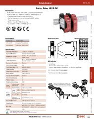
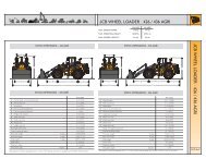
<strong>Rodney</strong> <strong>Hunt</strong> Rotovalves :<br />
Cut Out View<br />
Actuator<br />
Manual or Power<br />
(hydraulic or electric)<br />
Shaft<br />
Connects the mechanism<br />
to the plug.<br />
Lift-nut<br />
Lifts the plug.<br />
Lifter Lever<br />
Rotates the lift nut.<br />
Operator Rod<br />
Moves the cross head.<br />
Rotator Lever<br />
Turns the plug.<br />
Roller<br />
Contacts and turns the<br />
rotator lever after the plug<br />
has been raised.<br />
Seating Adjuster<br />
Limits crosshead travel.<br />
Crosshead<br />
Carries the roller and<br />
transmits linear motion to<br />
the lifter lever<br />
Guide Rods (2)<br />
Guarantee alignment and<br />
smooth crosshead travel.<br />
Body<br />
Rugged, integrally cast<br />
trunnions and mounting<br />
pads.<br />
Bearing<br />
Bronze or stainless<br />
steel. Assures long life,<br />
ease of operation.<br />
Seats<br />
Monel-to-Monel. Highly<br />
corrosion resistant.<br />
Drip tight shutoff.<br />
Plug<br />
100% circular waterway<br />
opening, fully skirted.<br />
Integrally cast trunnions.<br />
Head<br />
Aligns the plug and supports<br />
the mechanism.
<strong>Rodney</strong> <strong>Hunt</strong> Rotovalves :<br />
Water Hammer Control<br />
The smooth and linear operating cycle of the Rotovalve is<br />
highly effective in controlling surge and water hammer while<br />
providing precise flow regulation.<br />
Water hammer, a phenomenon occurring in pipelines<br />
carrying in<strong>com</strong>pressible fluids, is the result of a sudden<br />
change in fluid velocity. Such a change in velocity could be<br />
caused by a sudden closing or opening of a valve, which<br />
creates a series of pressure pulsations in the line. The<br />
intensity of the initial pressure pulsation can sometimes<br />
break the pipe. Water hammer must be a consideration in<br />
any system design.<br />
The magnitude of the increase in pressure from water<br />
hammer is a function of time and liquid velocity. It is<br />
generally accepted that the maximum pressure rise will<br />
occur in the first wave whenever the valve is closed<br />
<strong>com</strong>pletely within one period. One period is defined as the<br />
time it takes the shock wave to travel from the valve to the<br />
end of the pipe and return. Succeeding waves are<br />
progressively less in magnitude.<br />
The <strong>com</strong>plete closure of a valve in a time longer than one<br />
period limits the degree of pressure rise in the first wave.<br />
The longer the elapsed closing time, the lesser the<br />
magnitude of the first and succeeding waves. Controlled<br />
closing time is tile key to reducing the intensity of water<br />
hammer.<br />
A fully skirted Rotovalve is ideal for water hammer control<br />
because of its design and the ease by which the stroke time<br />
can be adjusted. The two orifices (influent and effluent)<br />
drop the unbalanced pressure in two stages, greatly<br />
reducing the potential for cavitation and vibration.
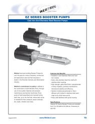
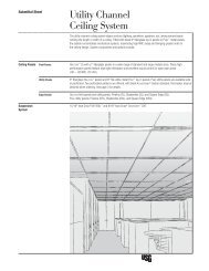
How does<br />
the cone valve<br />
operate?<br />
The Rotovalve cone valve is different from other through-ported<br />
valves (like the ball valve) in its unique seating / unseating<br />
operation.<br />
The plug is raised along the axis of the shaft to initiate opening<br />
of the valve, and lowered to <strong>com</strong>plete closing of the valve (See<br />
Figure 1). This action permits the plug to rotate freely on journal<br />
bearings during the entire opening/closing sequence which<br />
reduces torque and eliminates seat wear.<br />
Step 1: The closed position. The Rotovalve seats drip tight<br />
with the machined monel faces on both sides of the plug seating<br />
against the machined monel surfaces on each side of the body.<br />
Step 2: Lift actuation: The first movement of the actuator<br />
(manual, electric, or cylinder) moves the crosshead laterally<br />
toward the rotator lever. This initial lateral movement of the<br />
crosshead moves the lifter lever, which turns the lift nut and<br />
raises the plug away from the body seat. The plug has not<br />
turned.<br />
Step 3: Opening: Once the crosshead contacts the rotator<br />
lever, further lateral movement of the crosshead then turns the<br />
plug.<br />
Step 4: Opening: Close-to-open, and open-to-close<br />
sequence can be adjusted for water hammer control. The two<br />
orifices of the valve (influent and effluent) drop the unbalanced<br />
pressure in two stages, reducing the potential for cavitation and<br />
vibration.<br />
Step 5: Fully open:<br />
Once the plug is fully rotated, continued<br />
movement of the crosshead turns the lift nut, reseating the<br />
plug.<br />
1.<br />
2.<br />
3.<br />
4.<br />
5.<br />
Figure 1<br />
Actuator Mechanism Cross Section<br />
Mechanism Housing<br />
Crosshead<br />
Roller<br />
Guide Rod<br />
Rotator Lever<br />
Lifter Lever<br />
Lifter Link<br />
Figure 2
Materials and Dimensions<br />
Body, Plug and Head Castings ......................ASTM A126<br />
Class C cast iron (for 150 psi service) or ASTM A536<br />
Grade 65-45-12 ductile iron orA216 Grade WCB cast<br />
steel (for 250 psi service)<br />
Head and Body Bushing ......................................Bronze<br />
Mechanism Housing ........................................ Cast iron<br />
Cover.................................................................Cast iron<br />
Lift Nut .................................................................Bronze<br />
Crosshead ...........................................................Bronze<br />
Thrust Ring ............................................................ Steel<br />
Cylinder Operator<br />
SIZE<br />
6<br />
8<br />
10<br />
12<br />
14<br />
16<br />
18<br />
20<br />
24<br />
30<br />
36<br />
42<br />
48<br />
54<br />
60<br />
Typical Base for 12”<br />
Thru 24” Sizes Only<br />
N<br />
G<br />
X 1<br />
X<br />
X 1<br />
F (approx.)<br />
V=No. and Dia.<br />
Bolt Holes<br />
Sizes....................6”-84”<br />
K<br />
(Approx.)<br />
Roller........................................................................ Steel<br />
Guide Rods............................................... Stainless Steel<br />
Seat Rings...............................................................Monel<br />
Trunnion Bearings ....................Bronze or Stainless Steel<br />
Flanges .................... ANSI Class 125, 250, 300 or metric<br />
Valve Shaft .................... Stainless Steel ASTM Type 630<br />
O-Ring ..................................................................Buna-N<br />
Packing................................................Fiber and Graphite<br />
Packing Gland........................................................Bronze<br />
A<br />
125 Lb<br />
A<br />
250 Lb<br />
B E F G K N* U* V* X* X 1* Y* Y 1*<br />
23 24<br />
27 26 ½ 6¾ 10 9 1 (4)-1 10 3¾ 15 ¼ 6<br />
23 ½ 24 ½ 27 27 ½ 8¼ 10 10 ¾ 1 (4) -1 10 3¾ 15 ¼ 6<br />
28 29 ½ 27 28 ½ 9¾ 10 12 1 (4) -1 10 3¾ 15 ¼ 6<br />
31 32 ½ 14 37 34 ½ 13 ¼ 15 ½ 15 ¾ 1½ (4) -1 14 5 22 9½<br />
35 ½ 37 15 ½ 37 35 ½ 14 ¼ 15 ½ 16 ¾ 1½ (4) -1 14 5 22 9½<br />
39 40 17 37 36 ½ 16 ½ 15 ½ 19 1½ (4) -1 14 5 22 9½<br />
41 ¾<br />
47<br />
56<br />
64<br />
70 ½<br />
83 ¼<br />
88<br />
101<br />
43<br />
48<br />
57 ¾<br />
65 ¾<br />
74<br />
85<br />
90 ½<br />
19 ¼<br />
22 ¼<br />
26 ¼<br />
31 ½<br />
36 ½<br />
47<br />
47 ½<br />
54<br />
37<br />
49<br />
49<br />
56 ½<br />
56 ½<br />
67 ¼<br />
67 ¼<br />
37 ½<br />
47 ¾<br />
50 ½<br />
58 ¾<br />
61 ¾<br />
70<br />
92<br />
95<br />
18<br />
20 ¾<br />
22<br />
29 ½<br />
31<br />
38<br />
42<br />
51 ¼<br />
15 ½<br />
21<br />
21<br />
29 ¾<br />
29 ¾<br />
40 ½<br />
40 ½<br />
45<br />
20<br />
24 ¾<br />
26<br />
34<br />
35 ½<br />
42<br />
46<br />
54<br />
1½<br />
1¾<br />
1¾<br />
1¾<br />
1¾<br />
2¼<br />
2½<br />
2¾<br />
(4) -1<br />
(4) -1¾<br />
(4) -1¾<br />
(4) -2¼<br />
(4) -2¼<br />
(4) -2<br />
(4) -3<br />
(4)-3<br />
14<br />
20<br />
20<br />
28<br />
28<br />
42<br />
48<br />
48<br />
5<br />
8<br />
8<br />
11 ½<br />
11 ½<br />
15 ½<br />
21<br />
21<br />
22<br />
31 ½<br />
31 ½<br />
40 ½<br />
40 ½<br />
42<br />
46<br />
46<br />
9½<br />
14<br />
14<br />
18<br />
18<br />
18<br />
21<br />
21<br />
119 ½ 61<br />
102 56 45 58 ¾ 2¾ (4)-3 48 21 46 21<br />
Dimensions for all three methods of operation are identical, except for E and F, as shown in the drawings above.<br />
* Valve can be mounted in a horizontal or vertical line. Shaft can be horizontal or vertical. Actuator can be oriented in any direction relative to the shaft.<br />
APPROX.<br />
Wts. (Lbs.)<br />
730<br />
890<br />
1,235<br />
2,260<br />
2,520<br />
3,170<br />
3,515<br />
5,840<br />
8,320<br />
13,520<br />
19,400<br />
34,700<br />
43,900<br />
63,200<br />
80,600<br />
All dimensions are in inches. Dimensions for larger sizes or higher pressure ratings available upon request.<br />
125 Lb & 250 Lb FLANGES CONFORM FULLY TO ANSI B6.1 LATEST EDITION BOTH DIMENSIONALLY & FOR BOLTING PATTERN AND ALL FLANGES ARE FULLY FACED.<br />
E (Approx.)<br />
Motor Operator<br />
SIZE E F<br />
APPROX.<br />
Wts. (Lbs.)<br />
Manual Operator<br />
6 24 34 680<br />
F (approx.)<br />
8 24 35 820<br />
10 24 36 1,100<br />
12 27 41 2,050<br />
E<br />
(Approx.) 14 27 42 2,550<br />
16 27 43 2,910<br />
18 27 44 3,430<br />
20 32 49 5,300<br />
24 32 52 7,700<br />
30 36 70 13,000<br />
36 36 73 17,750<br />
42 48 80 31,570<br />
48 48 96 40,100<br />
54 63 95 57,500<br />
60 63 102 73,500<br />
B<br />
U<br />
G<br />
Y 1<br />
F (approx.)<br />
Y<br />
A<br />
Y 1<br />
E<br />
(Approx.)<br />
SIZE E F<br />
6<br />
8<br />
10<br />
12<br />
14<br />
16<br />
18<br />
20<br />
24<br />
30<br />
36<br />
42<br />
48<br />
54<br />
60<br />
25 ½<br />
25 ½<br />
25 ½<br />
30<br />
30<br />
30<br />
30<br />
34<br />
34<br />
41<br />
41<br />
48<br />
48<br />
63<br />
63<br />
28 ½<br />
29 ½<br />
30 ½<br />
36<br />
37<br />
38<br />
39<br />
49<br />
51<br />
68<br />
71<br />
74 ½<br />
77 ½<br />
85<br />
93<br />
APPROX.<br />
Wts. (Lbs.)<br />
610<br />
750<br />
1,030<br />
1,830<br />
2,330<br />
2,690<br />
3,200<br />
5,080<br />
7,480<br />
12,600<br />
17,350<br />
31,100<br />
39,600<br />
57,000<br />
72,800
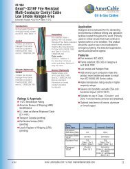
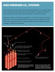
Characteristics<br />
k Values vs. Plug Angle<br />
Rotovalve Cv Values for Closed Systems<br />
K Value<br />
100<br />
10<br />
1.0<br />
0.1<br />
Rotovalve head Loss = K<br />
( full open valve)<br />
Size K Size K<br />
6 .0862 20 .0395<br />
8 .0614 24 .0375<br />
10 .0551 30 .0328<br />
12 .0488 36 .0289<br />
14 .0461 42 .0246<br />
16 .0430 48 .0236<br />
18 .0398 60 .0236<br />
Flow Coefficients Smaller Than Line Size<br />
D1<br />
Optional Cv Values<br />
REG.<br />
PATTERN<br />
LINE D1<br />
VALVE D2<br />
X<br />
IN. IN. APPROX.<br />
10<br />
12<br />
14<br />
16<br />
18<br />
8<br />
6<br />
10<br />
8<br />
6<br />
12<br />
10<br />
8<br />
14<br />
12<br />
10<br />
16<br />
14<br />
12<br />
For this curve use K values<br />
at left and upper set of plug<br />
angle figures.<br />
For this curve use K values<br />
at right and lower set of plug<br />
angle figures.<br />
Small valves<br />
Large valves<br />
K values vs. Plug angle<br />
Head Loss = kV 2<br />
2g<br />
Where V = full line velocity,<br />
not velocity through the valve.<br />
90 80 70 60 50 0 10<br />
.01 40 30 20 10<br />
Open Close (Not Sealed)<br />
Plug angle in degrees<br />
47.5<br />
51.12<br />
56.12<br />
53.5<br />
60.12<br />
63<br />
60.12<br />
62.5<br />
71.5<br />
67<br />
69.12<br />
77<br />
73.5<br />
73<br />
VENTURI<br />
SECTION<br />
CV<br />
STATION<br />
5170<br />
2070<br />
8790<br />
4150<br />
1850<br />
12710<br />
7120<br />
3700<br />
17452<br />
10930<br />
6210<br />
25720<br />
16520<br />
9620<br />
D2<br />
100,000<br />
10,000<br />
1000<br />
100<br />
K Value<br />
X<br />
(Optional arrangement – Weld Connection @ D1<br />
DIRECTION OF FLOW<br />
LINE D1<br />
VALVE D2<br />
X<br />
IN. IN. APPROX.<br />
20<br />
24<br />
30<br />
36<br />
VALVE<br />
SIZE<br />
6<br />
8<br />
10<br />
12<br />
14<br />
16<br />
18<br />
20<br />
24<br />
30<br />
36<br />
42<br />
48<br />
RESISTANCE<br />
FACTOR “K”<br />
18<br />
16<br />
14<br />
20<br />
18<br />
16<br />
24<br />
20<br />
18<br />
30<br />
24<br />
20<br />
80.75<br />
79<br />
78.5<br />
95<br />
89.75<br />
93<br />
116<br />
115<br />
117.75<br />
136<br />
138<br />
143<br />
PLUG ANGLE IN DEGREES FROM CLOSED<br />
90 80 70 60 50 40 30 20 10<br />
3596<br />
7423<br />
12165<br />
18466<br />
25613<br />
34820<br />
45515<br />
56191<br />
80915<br />
134100<br />
200780<br />
277053<br />
372356<br />
.46 1.9 5.2 13 31 74 180 580<br />
1566<br />
2784<br />
4350<br />
6265<br />
8527<br />
11138<br />
14096<br />
17403<br />
25060<br />
39157<br />
56386<br />
76748<br />
100242<br />
826<br />
1468<br />
2294<br />
3304<br />
4497<br />
5874<br />
7434<br />
9178<br />
13216<br />
20651<br />
29738<br />
40476<br />
52867<br />
CV<br />
STATION<br />
34130<br />
22690<br />
13800<br />
37690<br />
24760<br />
17140<br />
51750<br />
26990<br />
19710<br />
87000<br />
38870<br />
23150<br />
472<br />
839<br />
1311<br />
1888<br />
2567<br />
3356<br />
4248<br />
5244<br />
7552<br />
11880<br />
16993<br />
23129<br />
30210<br />
AWWA Long Pattern-<br />
To 24” Line Size<br />
AWWA Short Pattern-<br />
Above 24” Line Size<br />
VENTURI<br />
SECTION<br />
300<br />
534<br />
834<br />
1201<br />
1635<br />
2136<br />
2703<br />
3337<br />
4806<br />
7509<br />
10813<br />
14718<br />
19224<br />
1. The maximum controllable valve position is determined by the<br />
dynamic characteristics (k) of the <strong>com</strong>plete system, including<br />
the valve, the reducer and increaser sections.<br />
2. Estimates for a regulating valve size, excluding the line, the<br />
reducer and the increaser losses, are based on maximum<br />
valve control at the 80 Deg. from closed position.<br />
LINE D1<br />
VALVE D2<br />
X<br />
IN. IN. APPROX.<br />
42<br />
48<br />
54<br />
60<br />
193<br />
343<br />
536<br />
772<br />
1051<br />
1373<br />
1738<br />
2145<br />
3089<br />
4827<br />
6951<br />
9462<br />
12358<br />
36<br />
30<br />
24<br />
42<br />
36<br />
30<br />
48<br />
42<br />
36<br />
54<br />
48<br />
42<br />
123<br />
219<br />
342<br />
493<br />
671<br />
877<br />
1110<br />
1370<br />
1974<br />
3084<br />
4441<br />
6045<br />
7895<br />
154.5<br />
148<br />
166<br />
164.5<br />
180<br />
183.25<br />
193<br />
199<br />
211.25<br />
78<br />
139<br />
217<br />
313<br />
426<br />
556<br />
704<br />
870<br />
1253<br />
1957<br />
2819<br />
3837<br />
5012<br />
C v = 29.8 Dv<br />
2<br />
44<br />
78<br />
122<br />
176<br />
239<br />
312<br />
395<br />
488<br />
703<br />
1100<br />
1583<br />
2155<br />
2815<br />
1 K<br />
D v<br />
= Valve I.D. in<br />
inches<br />
CV<br />
STATION<br />
130900<br />
66030<br />
33990<br />
190600<br />
101700<br />
57840<br />
261400<br />
159200<br />
89300<br />
321600<br />
218200<br />
129800<br />
Other size variations available upon request.
<strong>Rodney</strong> <strong>Hunt</strong> Rotovalves :<br />
Actuation and Control<br />
Manual or Power Actuation<br />
Manual: Self -locking, threaded stem attached to a geared<br />
unit with handwheel, chain-wheel or operating nut input.<br />
Hydraulic: Cylinder using line pressure or separate<br />
external power source.<br />
Electric Motor: Available for open-close or throttling<br />
service, <strong>com</strong>plete with limit switches and torque switches<br />
as required. Manual override is standard. Also available for<br />
modulating service with position feedback for continuously<br />
adjustable automatic controls. Complete accessories are<br />
available and include indicator lights, integral reversing<br />
starters, push buttons, potentiometers, space heaters,<br />
sensors, transmitters, transducers and other control<br />
features.<br />
Depending upon the application, <strong>Rodney</strong> <strong>Hunt</strong> hydraulic<br />
systems for valve control offer specific advantages and<br />
economies over manual and electric actuation. Where<br />
several valves are operated by a single hydraulic operating<br />
system, for example, considerable cost savings can result.<br />
<strong>Rodney</strong> <strong>Hunt</strong> has the capability to design, manufacture,<br />
and test hydraulic systems <strong>com</strong>plete with associated<br />
electrical control panels. Start-up assistance is also<br />
available. These capabilities offer the consulting engineer,<br />
contractor, and end-user single-source responsibility for<br />
both the valve equipment and hydraulic actuation.<br />
Advantages of Hydraulic Actuation<br />
Economical. Hydraulic actuation is the most cost-effective<br />
type of power actuation currently available.<br />
Increased control Valve can be designed to open and<br />
close at different speeds, and to permit easy field<br />
adjustment of speed.<br />
Less wear. Hydraulic cylinders provide long, trouble-free<br />
service especially where valve cycles frequently, or is used<br />
for modulating service.<br />
Flexible functions Systems can vary from a simple<br />
pushbutton station to sophisticated programmable<br />
positioning.<br />
Emergency "fail-safe" operation. Can be easily<br />
configured to open or close valve in the event of power<br />
failure, line breakage, or other emergency.<br />
Hydraulic actuation system engineering includes<br />
development of hydraulic power units that respond to<br />
<strong>com</strong>puter instructions for exact valve positions, continuous<br />
monitoring, and emergency operation.
<strong>Rodney</strong> <strong>Hunt</strong> Rotovalves :<br />
Cone Valve Specifications<br />
General: The cone valve shall be the Rotovalve as<br />
manufactured by <strong>Rodney</strong> <strong>Hunt</strong> Company. It shall be a full ported<br />
valve and shall be <strong>com</strong>plete with actuator and accessories as<br />
specified herein.<br />
Operation: Operation of the cone valve shall employ an axial<br />
motion to lift the valve plug from its seat, followed by a 90°<br />
rotary motion of the plug to open the valve and axial motion to<br />
reseat it in the open position. Closing movement of the valve<br />
plug shall be in reverse order. It shall be designed to operate<br />
satisfactorily at the flow conditions specified.<br />
Valve Construction: The valve body shall be provided with<br />
seat rings of Monel metal electrically fused to the body<br />
waterway and sufficiently raised above the internal surface of<br />
the body to assure free operation. The valve shall be <strong>com</strong>plete<br />
with ANSI Class flanges to mate with adjacent equipment.<br />
The valve plug shall be fully skirted with integrally cast<br />
trunnions. It shall have a set of Monel seat rings electrically<br />
fused to the plug waterway and sufficiently raised above the<br />
extended surface of the plug to assure free operation. If sealing<br />
in the open position is required to prevent flow around the plug,<br />
a second set of seats shall be furnished. Trunnion bearings on<br />
the plug shall be bronze or stainless steel and shall mate with<br />
bronze or stainless steel bearings in the body and head.<br />
The head shall make a registered connection with the valve<br />
body to assure proper bearing alignment. It shall be designed to<br />
support the cone valve mechanism and operating forces.<br />
All valve castings shall be ASTM A126 Class C cast iron, ASTM<br />
A536 Grade 65-45-12 ductile iron, or ASTM A216 Grade WCB<br />
cast steel.<br />
The valve shaft shall be stainless steel Type 630 with 125,000<br />
psi minimum yield strength, and shall be pinned to the plug. The<br />
packing shall be fiber and graphite with a bronze adjustable<br />
packing gland.<br />
Mechanism Construction: The operating mechanism shall be<br />
totally enclosed in a cast iron housing with an integrally cast<br />
mounting bracket to assure proper alignment. The housing shall<br />
be designed for either right of left hand actuator mounting.<br />
The mechanism cover shall be cast iron and make a registered<br />
connection to tile mechanism housing. The cover shall be<br />
bronze bushed where the valve shaft extends through it. The<br />
bronze lift nut shall be contained <strong>com</strong>pletely within the<br />
mechanism housing with provision for external lubrication. The<br />
crosshead shall be of bronze B584 C86200 and shall travel on<br />
stainless steel guide rods. Two covered access holes shall be<br />
provided for access to the tube fittings on the crosshead. Ail<br />
indicator shall be mounted on the end of the valve shaft for local<br />
position indication.<br />
Actuator: Actuator will be sized to operate the valve from full<br />
open to full closed at rated pressure with a maximum of` 80<br />
ft./lb. of input torque on a manual actuator. The valve<br />
manufacturer shall be responsible for sizing electrical of<br />
cylinder actuators based on the flow conditions.<br />
Testing: Cone valve body and head shall be hydrostatically<br />
tested for 10 minutes at a test pressure of one and one-half<br />
times maximum working pressure for which the valve is<br />
intended. Under test, parts shall show no evidence of distress<br />
and shall be free from any leaks.<br />
When fully shop assembled, each cone valve shall be leak<br />
tested at the rated pressure. Leakage shall not exceed 0.4 oz<br />
/min /inch of diameter.<br />
Pump Check Controls:<br />
The pump check controls shall be<br />
supplied, mounted and tested by the valve manufacturer. They<br />
shall consist of a 4-way solenoid valve with manual override,<br />
speed control valves, open /close limit switches, pump<br />
shutdown limit switch and a pressure switch positioned on the<br />
upstream side of the valve. When the pump reaches the<br />
designated pressure, the pressure switch is activated,<br />
energizing the solenoid control valve causing the cone valve to<br />
open at a predetermined rate. To shutdown pump operation, the<br />
solenoid control valve is de-energized causing the cone valve to<br />
close. When the cone valve is approximately 95% closed the<br />
pump shutdown limit switch shall be activated, shutting down<br />
the pump. The opening and closing speeds shall be<br />
independently adjusted from __ seconds to __ seconds.