TCP-IP and IPX routing tutorial.pdf - Leet Upload
TCP-IP and IPX routing tutorial.pdf - Leet Upload
TCP-IP and IPX routing tutorial.pdf - Leet Upload

Create successful ePaper yourself
Turn your PDF publications into a flip-book with our unique Google optimized e-Paper software.
sangoma content page<br />
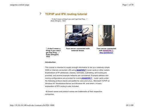
<strong>TCP</strong>/<strong>IP</strong> <strong>and</strong> <strong>IP</strong>X <strong>routing</strong> <strong>tutorial</strong><br />
"It don't mean a thing if you cain't get that Ping...."<br />
Duke Ellington, 1932<br />
"..It don't mean a<br />
thing if you cain't<br />
get that Ping...."<br />
Duke Ellington,<br />
1932<br />
Introduction<br />
This <strong>tutorial</strong> is intended to supply enough information to set up a relatively simple<br />
WAN or Internet-connected LAN using WANP<strong>IP</strong>E router cards or other routers.<br />
Explanations of <strong>IP</strong> addresses, classes, netmasks, subnetting, <strong>and</strong> <strong>routing</strong> are<br />
provided, <strong>and</strong> several example networks are considered. Example address <strong>and</strong><br />
<strong>routing</strong> configurations are provided for runningWANP<strong>IP</strong>E router cards under<br />
the following protocol stacks <strong>and</strong> platforms: Unix <strong>and</strong> Linux., Microsoft <strong>TCP</strong>/<strong>IP</strong> on<br />
Windows NT Workstation/Server <strong>and</strong> Windows 95, <strong>and</strong> others. A basic<br />
explanation of <strong>IP</strong>X <strong>routing</strong> is also included.<br />
All br<strong>and</strong> names <strong>and</strong> product names are trademarks of their respective<br />
companies.<br />
http://10.10.10.140/web-dev/content.cfm?ID=1000<br />
Your server connected with<br />
external boxes<br />
Your server connected<br />
with WANP<strong>IP</strong>E.<br />
Any questions?<br />
Page 1 of 30<br />
10/11/00
sangoma content page<br />
The <strong>IP</strong> Address <strong>and</strong> Classes<br />
Hosts <strong>and</strong> networks<br />
<strong>IP</strong> addressing is based on the concept of hosts <strong>and</strong> networks. A host is<br />
essentially anything on the network that is capable of receiving <strong>and</strong> transmitting<br />
<strong>IP</strong> packets on the network, such as a workstation or a router. It is not to be<br />
confused with a server: servers <strong>and</strong> client workstations are all <strong>IP</strong> hosts.<br />
The hosts are connected together by one or more networks. The <strong>IP</strong> address of<br />
any host consists of its network address plus its own host address on the<br />
network. <strong>IP</strong> addressing, unlike, say, <strong>IP</strong>X addressing, uses one address<br />
containing both network <strong>and</strong> host address. How much of the address is used for<br />
the network portion <strong>and</strong> how much for the host portion varies from network to<br />
network.<br />
<strong>IP</strong> addressing<br />
http://10.10.10.140/web-dev/content.cfm?ID=1000<br />
An <strong>IP</strong> address is 32 bits wide, <strong>and</strong> as discussed, it is composed of two parts: the<br />
network number, <strong>and</strong> the host number [1, 2, 3]. By convention, it is expressed<br />
as four decimal numbers separated by periods, such as "200.1.2.3" representing<br />
the decimal value of each of the four bytes. Valid addresses thus range from<br />
0.0.0.0 to 255.255.255.255, a total of about 4.3 billion addresses. The first few<br />
bits of the address indicate the Class that the address belongs to:<br />
Class Prefix Network Number Host Number<br />
A 0 Bits 1-7 Bits 8-31<br />
B 10 Bits 2-15 Bits 16-31<br />
C 110 Bits 3-24 Bits 25-31<br />
D 1110 N/A<br />
E 1111 N/A<br />
The bits are labeled in network order, so that the first bit is bit 0 <strong>and</strong> the last is bit<br />
31, reading from left to right. Class D addresses are multicast, <strong>and</strong> Class E are<br />
Page 2 of 30<br />
10/11/00
sangoma content page<br />
reserved. The range of network numbers <strong>and</strong> host numbers may then be<br />
derived:<br />
http://10.10.10.140/web-dev/content.cfm?ID=1000<br />
Class Range of Net Numbers Range of Host Numbers<br />
A 0 to 126 0.0.1 to 255.255.254<br />
B 128.0 to 191.255 0.1 to 255.254<br />
C 192.0.0 to 254.255.255 1 to 254<br />
Any address starting with 127 is a loop back address <strong>and</strong> should never be used<br />
for addressing outside the host. A host number of all binary 1's indicates a<br />
directed broadcast over the specific network. For example, 200.1.2.255 would<br />
indicate a broadcast over the 200.1.2 network. If the host number is 0, it indicates<br />
"this host". If the network number is 0, it indicates "this network" [2]. All the<br />
reserved bits <strong>and</strong> reserved addresses severely reduce the available <strong>IP</strong><br />
addresses from the 4.3 billion theoretical maximum. Most users connected to the<br />
Internet will be assigned addresses within Class C, as space is becoming very<br />
limited. This is the primary reason for the development of <strong>IP</strong>v6, which will have<br />
128 bits of address space.<br />
Basic <strong>IP</strong> Routing<br />
Classed <strong>IP</strong> Addressing <strong>and</strong> the Use of ARP<br />
Consider a small internal <strong>TCP</strong>/<strong>IP</strong> network consisting of one Ethernet segment<br />
<strong>and</strong> three nodes. The <strong>IP</strong> network number of this Ethernet segment is 200.1.2.<br />
The host numbers for A, B, <strong>and</strong> C are 1, 2, <strong>and</strong> 3 respectively. These are Class<br />
C addresses, <strong>and</strong> therefore allow for up to 254 nodes on this network segment.<br />
Each of these nodes have corresponding Ethernet addresses, which are six<br />
bytes long. They are normally written in hexadecimal form separated by dashes<br />
(02-FE-87-4A-8C-A9 for example).<br />
Page 3 of 30<br />
10/11/00
sangoma content page<br />
http://10.10.10.140/web-dev/content.cfm?ID=1000<br />
In the diagram above <strong>and</strong> subsequent diagrams, we have emphasized the<br />
network number portion of the <strong>IP</strong> address by showing it in red.<br />
Suppose that A wanted to send a packet to C for the first time, <strong>and</strong> that it knows<br />
C's <strong>IP</strong> address. To send this packet over Ethernet, A would need to know C's<br />
Ethernet address. The Address Resolution Protocol (ARP) is used for the<br />
dynamic discovery of these addresses [1].<br />
ARP keeps an internal table of <strong>IP</strong> address <strong>and</strong> corresponding Ethernet address.<br />
When A attempts to send the <strong>IP</strong> packet destined to C, the ARP module does a<br />
lookup in its table on C's <strong>IP</strong> address <strong>and</strong> will discover no entry. ARP will then<br />
broadcast a special request packet over the Ethernet segment, which all nodes<br />
will receive. If the receiving node has the specified <strong>IP</strong> address, which in this case<br />
is C, it will return its Ethernet address in a reply packet back to A. Once A<br />
receives this reply packet, it updates its table <strong>and</strong> uses the Ethernet address to<br />
direct A's packet to C. ARP table entries may be stored statically in some cases,<br />
or it keeps entries in its table until they are "stale" in which case they are<br />
Consider now two separate Ethernet networks that are joined by a PC, C, acting<br />
as an <strong>IP</strong> router (for instance, if you have two Ethernet segments on your server).<br />
Page 4 of 30<br />
10/11/00
sangoma content page<br />
Device C is acting as a router between these two networks. A router is a device<br />
that chooses different paths for the network packets, based on the addressing of<br />
the <strong>IP</strong> frame it is h<strong>and</strong>ling. Different routes connect to different networks. The<br />
router will have more than one address as each route is part of a different<br />
network.<br />
http://10.10.10.140/web-dev/content.cfm?ID=1000<br />
Since there are two separate Ethernet segments, each network has its own<br />
Class C network number. This is necessary because the router must know which<br />
network interface to use to reach a specific node, <strong>and</strong> each interface is assigned<br />
a network number. If A wants to send a packet to E, it must first send it to C who<br />
can then forward the packet to E. This is accomplished by having A use C's<br />
Ethernet address, but E's <strong>IP</strong> address. C will receive a packet destined to E <strong>and</strong><br />
will then forward it using E's Ethernet address. These Ethernet addresses are<br />
obtained using ARP as described earlier.<br />
If E was assigned the same network number as A, 200.1.2, A would then try to<br />
Page 5 of 30<br />
10/11/00
sangoma content page<br />
reach E in the same way it reached C in the previous example - by sending an<br />
ARP request <strong>and</strong> hoping for a reply. However, because E is on a different<br />
physical wire, it will never see the ARP request <strong>and</strong> so the packet cannot be<br />
delivered. By specifying that E is on a different network, the <strong>IP</strong> module in A will<br />
know that E cannot be reached without having it forwarded by some node on the<br />
same network as A.<br />
http://10.10.10.140/web-dev/content.cfm?ID=1000<br />
Direct vs. Indirect Routing<br />
Direct <strong>routing</strong> was observed in the first example when A communicated with C. It<br />
is also used in the last example for A to communicate with B. If the packet does<br />
not need to be forwarded, i.e. both the source <strong>and</strong> destination addresses have<br />
the same network number, direct <strong>routing</strong> is used.<br />
Indirect <strong>routing</strong> is used when the network numbers of the source <strong>and</strong><br />
destination do not match. This is the case where the packet must be forwarded<br />
by a node that knows how to reach the destination (a router).<br />
In the last example, A wanted to send a packet to E. For A to know how to reach<br />
E, it must be given <strong>routing</strong> information that tells it who to send the packet to in<br />
order to reach E. This special node is the "gateway" or router between the two<br />
networks. A Unix-style method for adding a <strong>routing</strong> entry to A is<br />
route add [destination_ip] [gateway] [metric]<br />
Where the metric value is the number of hops to the destination. In this case,<br />
route add 200.1.3.2 200.1.2.3 1<br />
will tell A to use C as the gateway to reach E. Similarly, for E to reach A,<br />
route add 200.1.2.1 200.1.3.10 1<br />
will be used to tell E to use C as the gateway to reach A. It is necessary that C<br />
Page 6 of 30<br />
10/11/00
sangoma content page<br />
http://10.10.10.140/web-dev/content.cfm?ID=1000<br />
have two <strong>IP</strong> addresses - one for each network interface. This way, A knows from<br />
C's <strong>IP</strong> address that it is on its own network, <strong>and</strong> similarly for E. Within C, the<br />
<strong>routing</strong> module will know from the network number of each interface which one to<br />
use for forwarding <strong>IP</strong> packets.<br />
In most cases it will not be necessary to manually add this <strong>routing</strong> entry. It would<br />
normally be sufficient to set up C as the default gateway for all other nodes on<br />
both networks. The default gateway is the <strong>IP</strong> address of the machine to send all<br />
packets to that are not destined to a node on the directly-connected network. The<br />
<strong>routing</strong> table in the default gateway will be set up to forward the packets properly,<br />
which will be discussed in detail later.<br />
Static vs. Dynamic Routing<br />
Static <strong>routing</strong> is performed using a preconfigured <strong>routing</strong> table which remains in<br />
effect indefinitely, unless it is changed manually by the user. This is the most<br />
basic form of <strong>routing</strong>, <strong>and</strong> it usually requires that all machines have statically<br />
configured addresses, <strong>and</strong> definitely requires that all machines remain on their<br />
respective networks. Otherwise, the user must manually alter the <strong>routing</strong> tables<br />
on one or more machines to reflect the change in network topology or<br />
addressing. Usually at least one static entry exists for the network interface, <strong>and</strong><br />
is normally created automatically when the interface is configured.<br />
Dynamic <strong>routing</strong> uses special <strong>routing</strong> information protocols to automatically<br />
update the <strong>routing</strong> table with routes known by peer routers. These protocols are<br />
grouped according to whether they are Interior Gateway Protocols (IGPs) or<br />
Exterior Gateway Protocols. Interior gateway protocols are used to distribute<br />
<strong>routing</strong> information inside of an Autonomous System (AS). An AS is a set of<br />
routers inside the domain administered by one authority. Examples of interior<br />
gateway protocols are OSPF <strong>and</strong> R<strong>IP</strong>. Exterior gateway protocols are used for<br />
inter-AS <strong>routing</strong>, so that each AS may be aware of how to reach others<br />
Page 7 of 30<br />
10/11/00
sangoma content page<br />
throughout the Internet. Examples of exterior gateway protocols are EGP <strong>and</strong><br />
BGP. See RFC 1716 [11] for more information on <strong>IP</strong> router operations.<br />
WANP<strong>IP</strong>E Routing<br />
WANP<strong>IP</strong>E is a network interface, <strong>and</strong> does not actually route packets<br />
according to <strong>IP</strong> address, or maintain <strong>IP</strong> <strong>routing</strong> information. Packet <strong>routing</strong><br />
between interfaces is accomplished by the protocol stack, which can send <strong>IP</strong><br />
based dynamic <strong>routing</strong> protocols over WANP<strong>IP</strong>E . The information <strong>and</strong><br />
protocols needed for dynamic <strong>routing</strong> are h<strong>and</strong>led by the protocol stack, <strong>and</strong> not<br />
at the WANP<strong>IP</strong>E level. In practice, it is almost always better to use explicit<br />
static <strong>routing</strong> table entries rather than relying on dynamic <strong>routing</strong>.<br />
Advanced <strong>IP</strong> Routing<br />
The Netmask<br />
When setting up each node with its <strong>IP</strong> address, the netmask must also be<br />
specified. This mask is used to specify which part of the address is the network<br />
number part, <strong>and</strong> which is the host part. This is accomplished by a logical<br />
bitwise-AND between the netmask <strong>and</strong> the <strong>IP</strong> address. The result specifies the<br />
network number. For Class C, the netmask will always be 255.255.255.0; for<br />
Class B, the netmask will always be 255.255.0.0; <strong>and</strong> so on. When A sent a<br />
packet to E in the last example, A knew that E wasn't on its network segment by<br />
comparing A's network number 200.1.2 to the value resulting from the bitwise-<br />
AND between the netmask 255.255.255.0 <strong>and</strong> the <strong>IP</strong> address of E, 200.1.3.2,<br />
which is 200.1.3.<br />
The netmask becomes very important, <strong>and</strong> more complicated, when "classless"<br />
addressing is used.<br />
http://10.10.10.140/web-dev/content.cfm?ID=1000<br />
Page 8 of 30<br />
10/11/00
sangoma content page<br />
http://10.10.10.140/web-dev/content.cfm?ID=1000<br />
Hierarchical Sub-Allocation of Class C Addresses<br />
To make more efficient use of Class C addresses in the Internet community,<br />
these addresses are subnetted hierarchically from the service provider to the<br />
organization. They are allocated bitmask-oriented subsets of the provider's<br />
address space [4, 5]. These are classless addresses.<br />
Consider the following example of a small organization consisting of two Ethernet<br />
segments connecting to an Internet service provider using a WAN router that<br />
emulates an additional network segment, such as WANP<strong>IP</strong>E . The service<br />
provider has been allocated several different Class C addresses to be used for<br />
its clients. This particular organization has been allocated the network number<br />
210.20.30, <strong>and</strong> the gateway address at the provider end is 210.20.30.254.<br />
Page 9 of 30<br />
10/11/00
sangoma content page<br />
We have exp<strong>and</strong>ed the last byte of the <strong>IP</strong> address so that we can show the<br />
network subaddressing. The st<strong>and</strong>ard <strong>IP</strong> address nomenclature is shown below<br />
this exp<strong>and</strong>ed version.<br />
http://10.10.10.140/web-dev/content.cfm?ID=1000<br />
If the organization happened to have just one computer, C, <strong>and</strong> the entire Class<br />
C address is available for use, then the <strong>IP</strong> address for C may be anything in the<br />
range 210.20.30.1 to 210.20.30.253, <strong>and</strong> its default gateway would be<br />
210.20.30.254 with netmask 255.255.255.0.<br />
However, with two networks plus WANP<strong>IP</strong>E , which must also be on its own<br />
network, the Class C address must somehow be subnetted. This is<br />
Page 10 of 30<br />
10/11/00
sangoma content page<br />
http://10.10.10.140/web-dev/content.cfm?ID=1000<br />
accomplished by using one or more of the bits that are normally allocated to the<br />
host number as part of the Class C address, in order to extend the size of the<br />
network number. In this case, 210.20.30 has been extended to include four<br />
networks, <strong>and</strong> the netmask has changed to 255.255.255.192 to reflect the<br />
additional use of two bits for the network number in the <strong>IP</strong> address.<br />
Strictly speaking, only subnets of two bits or more are legal, <strong>and</strong> any any subnet<br />
with subnet portion of the mask all zeros or all ones is illegal. But many <strong>TCP</strong>/<strong>IP</strong><br />
stacks used by WANP<strong>IP</strong>E will allow you to violate these rules, leading to a<br />
considerable saving in useful addresses. See our Appendix on the subject.<br />
Writing the netmask 255.255.255.192 in binary (from FFFFFFC0 in hex) is<br />
11111111/11111111/11111111/11000000, with /' separating the bytes for clarity.<br />
Since the organization is allocated all of 210.20.30 (D2141E hex), it has the use<br />
of the four following network numbers (in binary):<br />
Net# <strong>IP</strong> Network Number<br />
0 11010010/00010100/00011110/00<br />
1 11010010/00010100/00011110/01<br />
2 11010010/00010100/00011110/10<br />
3 11010010/00010100/00011110/11<br />
This leaves 6 bits at the end to use for host number, leaving space for 62 host<br />
nodes per network (all 0's <strong>and</strong> all 1's are reserved). The following addresses are<br />
therefore valid for hosts to use:<br />
Net# Address Range<br />
0 210.20.30.1 to 210.20.30.62<br />
1 210.20.30.65 to 210.20.30.126<br />
2 210.20.30.129 to 210.20.30.190<br />
3 210.20.30.193 to 210.20.30.254<br />
Page 11 of 30<br />
10/11/00
sangoma content page<br />
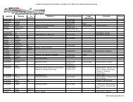
In this example, Net#2 is reserved for future use. The <strong>IP</strong> addresses <strong>and</strong><br />
netmasks for each interface are:<br />
Interface <strong>IP</strong> Address Netmask<br />
Node A 210.20.30.1 255.255.255.192<br />
Node B 210.20.30.2 255.255.255.192<br />
Node C (AB) 210.20.30.10 255.255.255.192<br />
Node C (DE) 210.20.30.70 255.255.255.192<br />
Node C (WAN) 210.20.30.200 255.255.255.192<br />
Node D 210.20.30.81 255.255.255.192<br />
Node E 210.20.30.82 255.255.255.192<br />
The <strong>routing</strong> tables will be set for each node as follows. The destination address<br />
0.0.0.0 indicates the default destination, if no other specific routes are configured<br />
for the given packet destination. This default destination is where all packets will<br />
be sent, <strong>and</strong> it is assumed that this destination is capable of forwarding these<br />
packets to the ultimate destination, or to another router along the appropriate<br />
path.<br />
Node A:<br />
http://10.10.10.140/web-dev/content.cfm?ID=1000<br />
Network Address Netmask Gateway Interface<br />
0.0.0.0 0.0.0.0 210.20.30.10 210.20.30.1<br />
210.20.30.0 255.255.255.192 210.20.30.1 210.20.30.1<br />
Node B:<br />
Network Address Netmask Gateway Interface<br />
0.0.0.0 0.0.0.0 210.20.30.10 210.20.30.2<br />
210.20.30.0 255.255.255.192 210.20.30.2 210.20.30.2<br />
Node C:<br />
Network Address Netmask Gateway Interface<br />
0.0.0.0 0.0.0.0 210.20.30.254 210.20.30.200<br />
Page 12 of 30<br />
10/11/00
sangoma content page<br />
http://10.10.10.140/web-dev/content.cfm?ID=1000<br />
210.20.30.0 255.255.255.192 210.20.30.10 210.20.30.10<br />
210.20.30.64 255.255.255.192 210.20.30.70 210.20.30.70<br />
210.20.30.192 255.255.255.192 210.20.30.200 210.20.30.200<br />
Node D:<br />
Network Address Netmask Gateway Interface<br />
0.0.0.0 0.0.0.0 210.20.30.70 210.20.30.81<br />
210.20.30.64 255.255.255.192 210.20.30.81 210.20.30.81<br />
Node E:<br />
Network Address Netmask Gateway Interface<br />
0.0.0.0 0.0.0.0 210.20.30.70 210.20.30.82<br />
210.20.30.64 255.255.255.192 210.20.30.82 210.20.30.82<br />
Node G:<br />
Network Address Netmask Gateway Interface<br />
210.20.30.0 255.255.255.0 210.20.30.200 210.20.30.254<br />
(Plus all other pertinent entries)<br />
The metric value, or hop count, is optional, but would be 0 for all gateways that<br />
are the same as the hosts, <strong>and</strong> greater than 0 if the destination is reached via<br />
one or more gateways. The metric for the default routes are indeterminate, but<br />
would always be at least 1.<br />
For example, if D sent an ICMP echo request packet out onto the Internet, let's<br />
say to address 140.51.120.30, then first D would AND the netmask<br />
255.255.255.192 with 140.51.120.30 to determine the network number. It would<br />
then find that it does not match the network number 210.20.30.64, <strong>and</strong> so it<br />
chooses the default route which points to the gateway 210.20.30.70. It then uses<br />
the Ethernet address of Node C (DE) to forward the <strong>IP</strong> packet to the gateway.<br />
When C receives this packet, it will see that it is destined to 140.51.120.30. It<br />
checks all the routes in its table <strong>and</strong> determines that this address is not located<br />
on any of the listed networks in the <strong>routing</strong> table, <strong>and</strong> so it chooses the default<br />
route. It uses the WAN interface, of <strong>IP</strong> address 210.20.30.200 to send the packet<br />
to 210.20.30.254 (G). From then on, the packet will propagate from gateway to<br />
gateway until it reaches 140.51.120.30. When this node replies, the packet will<br />
Page 13 of 30<br />
10/11/00
sangoma content page<br />
http://10.10.10.140/web-dev/content.cfm?ID=1000<br />
be inbound on interface 210.20.30.200 (C) with destination address 210.20.30.81<br />
(D). Node C will discover that 210.20.30.81 is on the 210.20.30.64 network <strong>and</strong><br />
uses the interface 210.20.30.70 to send the packet back home to D.<br />
<strong>TCP</strong>/<strong>IP</strong> Setup Examples by Protocol Stack <strong>and</strong><br />
Platform<br />
Please note that there are some additional restrictions on <strong>IP</strong> subnetting<br />
addresses that can be used, see the Appendix.<br />
Two examples will be presented to explain how to set up the <strong>IP</strong> addressing <strong>and</strong><br />
<strong>routing</strong> information when connecting to an Internet service provider using<br />
WANP<strong>IP</strong>E . The first case is when only one machine will be connected, <strong>and</strong><br />
the other case describes the connection of a LAN to the Internet. The third<br />
example briefly illustrates the addressing <strong>and</strong> <strong>routing</strong> techniques for connecting<br />
two LANs over a point-to-point WAN connection.<br />
Example 1: Single Node Connection to WAN Gateway<br />
Assume that the node PC with WANP<strong>IP</strong>E is assigned the <strong>IP</strong> address<br />
210.20.30.45, <strong>and</strong> that the gateway address is 199.99.88.77.<br />
The netmask for A may be set to 255.255.255.255, indicating no other nodes on<br />
the local network, <strong>and</strong> the gateway is set to 199.99.88.77. A default route must<br />
be set up at Node A as well, which provides the route for all packets whose<br />
destination does not corresponding to any specific <strong>routing</strong> entries.<br />
Page 14 of 30<br />
10/11/00
sangoma content page<br />
Node A:<br />
Network Address Netmask Gateway Interface<br />
0.0.0.0 0.0.0.0 199.99.88.77 210.20.30.45<br />
Node G:<br />
Network Address Netmask Gateway Interface<br />
210.20.30.45 255.255.255.255 199.99.88.77 199.99.88.77<br />
(Plus all other pertinent entries)<br />
The <strong>routing</strong> for Node G is highly dependent on the context, <strong>and</strong> the above entry<br />
only serves as an example. The netmask of all 1's in this case is used to only<br />
allow packets destined to 210.20.30.45 to be forwarded to Node A, as there may<br />
be 253 other nodes connected in a similar way under this Class C network<br />
199.99.88.0.<br />
http://10.10.10.140/web-dev/content.cfm?ID=1000<br />
When the protocol stack's configuration asks for a default gateway, specifying<br />
199.99.88.77 will cause the default <strong>routing</strong> entry 0.0.0.0 to be added<br />
automatically. It must be added manually if for some reason the stack does not<br />
ask for it. The specific methods of configuring each protocol stack will be<br />
explained in detail in Example 2.<br />
Example 2: LAN Connection to WAN Gateway<br />
The following network topology will be used as an example, where one LAN is<br />
connected to the Internet for simplicity. This will also demonstrate the use of a<br />
different netmask for creating two Class C subnets. Note however that the<br />
remote WAN gateway may have an <strong>IP</strong> address outside the local Class C<br />
network, in which case the local WAN gateway interface will usually have an <strong>IP</strong><br />
address on the same network as the remote WAN gateway. If this is the case,<br />
subnetting as shown below may not be necessary, unless more than one local<br />
network segment is involved.<br />
Networks 210.20.30.129->191, 210.20.30.65->127<br />
Netmask 255.255.255.192<br />
Page 15 of 30<br />
10/11/00
sangoma content page<br />
http://10.10.10.140/web-dev/content.cfm?ID=1000<br />
Node A is one of the many workstations on the Ethernet segment Net 0. Node Z<br />
with WANP<strong>IP</strong>E is the gateway from this Ethernet to the Internet service<br />
provider's gateway machine G. Some of the other workstations have been<br />
labeled as B to Y for illustration, but will not be referred to in this example as their<br />
setup will be the same as for A.<br />
In this case, we are being more compliant with the subnetting rules than in the<br />
previous example. Only two subnets are needed, but we are using 2 bits for the<br />
subnetting mask, as subnet 00 <strong>and</strong> 11 are strictly speaking, illegal. Writing the<br />
netmask 255.255.255.192 in binary (from FFFFFFC0 in hex) is<br />
11111111/11111111/11111111/11000000, with /' separating the bytes for clarity.<br />
Since the organization is allocated all of 210.20.30 (D2141E hex), it has the use<br />
of the two following network numbers (in binary):<br />
Net# <strong>IP</strong> Network Number<br />
0 11010010/00010100/10011110/01<br />
1 11010010/00010100/01011110/10<br />
This leaves 6 bits at the end to use for host number, leaving space for 63 host<br />
nodes per network (all 0's <strong>and</strong> all 1's are reserved). The following addresses are<br />
Page 16 of 30<br />
10/11/00
sangoma content page<br />
therefore valid for hosts to use:<br />
Net# Address Range<br />
0 210.20.30.129 to 210.20.30.191<br />
1 210.20.30.65 to 210.20.30.127<br />
The <strong>routing</strong> tables will be set for each node as follows. Note that the destination address<br />
0.0.0.0 indicates the default destination, if no other specific routes are indicated.<br />
Interface <strong>IP</strong> Address Netmask<br />
Node A 210.20.30.129 255.255.255.192<br />
Node Z (Net 0) 210.20.30.191 255.255.255.192<br />
Node Z (Net 1) 210.20.30.65 255.255.255.192<br />
The <strong>routing</strong> tables will be set for each node as follows. Note that the destination<br />
address 0.0.0.0 indicates the default destination, if no other specific routes are<br />
indicated.<br />
http://10.10.10.140/web-dev/content.cfm?ID=1000<br />
Node A:<br />
Network Address Netmask Gateway Interface<br />
0.0.0.0 0.0.0.0 210.20.30.191 210.20.30.129<br />
210.20.30.128 255.255.255.192 210.20.30.129 210.20.30.129<br />
Node Z:<br />
Network Address Netmask Gateway Interface<br />
0.0.0.0 0.0.0.0 210.20.30.127 210.20.30.65<br />
210.20.30.128 255.255.255.192 210.20.30.191 210.20.30.191<br />
210.20.30.64 255.255.255.192 210.20.30.65 210.20.30.65<br />
Node G:<br />
Network Address Netmask Gateway Interface<br />
210.20.30.0 255.255.255.0 210.20.30.65 210.20.30.127<br />
(Plus all other pertinent entries)<br />
Windows 9x, Windows 2000 <strong>and</strong> Windows NT<br />
Windows 95 will likely be used as a workstation at Node A, although it could be<br />
made to function as a simple static router if necessary. Windows NT or Windows<br />
2000 Workstation or Server may be used as the gateway at Node Z . Dynamic<br />
Page 17 of 30<br />
10/11/00
sangoma content page<br />
<strong>routing</strong> is not well supported by the Windows platforms. All routes should be<br />
statically configured.<br />
Windows 9x, Windows 2000 or Windows NT at Node A<br />
The user interfaces for configuring the Ethernet adapter under Win NT <strong>and</strong> Win<br />
95are slightly different, but they ask for the same information. Choose to<br />
configure the <strong>TCP</strong>/<strong>IP</strong> protocol for the Ethernet adapter in all these cases, <strong>and</strong> set<br />
the following.<br />
<strong>IP</strong> Address: 210.20.30.129<br />
SubNet Mask: 255.255.255.192<br />
Default Gateway: 210.20.30.191<br />
The advanced settings don't need to be changed, except possibly for enabling<br />
DNS or LMHOSTS lookup.<br />
The <strong>routing</strong> table may be displayed by typing route print in an MS-DOS box. It<br />
should correspond to the <strong>routing</strong> table shown above for Node A. The adapter<br />
configuration is displayed by running ipconfig in Windows NT or winipcfg in<br />
Windows 9x.<br />
http://10.10.10.140/web-dev/content.cfm?ID=1000<br />
Consult the Windows 9x Resource Kit On-Line Help [10] under the <strong>TCP</strong>/<strong>IP</strong><br />
protocol in the Network Technical Discussion heading for more information on<br />
configuring <strong>TCP</strong>/<strong>IP</strong> under Windows 9x.<br />
Windows 9x, Windows 2000 or Windows NT at Node Z<br />
Choose to configure the <strong>TCP</strong>/<strong>IP</strong> protocol in Network Settings. It is assumed at<br />
this point that the Ethernet <strong>and</strong> WANP<strong>IP</strong>E adapters have already been<br />
installed. Set the following for each adapter:<br />
Ethernet Adapter<br />
<strong>IP</strong> Address: 210.20.30.191<br />
SubNet Mask: 255.255.255.192<br />
Default Gateway: [blank]<br />
Page 18 of 30<br />
10/11/00
sangoma content page<br />
sangoma WANP<strong>IP</strong>E Adapter<br />
<strong>IP</strong> Address: 210.20.30.65<br />
SubNet Mask: 255.255.255.192<br />
Default Gateway: 210.20.30.65<br />
Note that the system has only ONE gateway! The gateway section on the<br />
Ethernet side is left blank. The <strong>routing</strong> table may be displayed by typing route<br />
print in an MS-DOS box. It should correspond to the <strong>routing</strong> table shown above<br />
for Node Z. The adapter configuration is displayed by running ipconfig.<br />
For more information on configuring Windows NT Server in this role, consult the<br />
"Microsoft Windows NT Server <strong>TCP</strong>/<strong>IP</strong>" manual [9]. It explains in detail the use of<br />
DNS, WINS, HOSTS, LMHOSTS, etc.<br />
Unix <strong>and</strong> Linux implementations of WANP<strong>IP</strong>E<br />
The configuration for Node Z is presented, which can easily be adapted to Node<br />
A by simplification.<br />
ifconfig eth0 inet 210.20.30.191 netmask 0xffffffC0<br />
ifconfig wanpipe1_ppp0 inet 210.20.30.65 netmask 0xffffffC0<br />
route add default 210.20.30.65<br />
It is assumed the Ethernet device eth0 <strong>and</strong> the WANP<strong>IP</strong>E device<br />
wanpipe1_ppp0 are properly installed. These are example interface names. The<br />
metric for the default route can be anything above 0. See reference [7].<br />
Use netstat to view the <strong>routing</strong> table <strong>and</strong> interface configuration, as well as<br />
ifconfig. The dynamic <strong>routing</strong> protocols R<strong>IP</strong>, BGP, OSPF <strong>and</strong> EGP are<br />
supported.<br />
NetWare Server<br />
http://10.10.10.140/web-dev/content.cfm?ID=1000<br />
NetWare <strong>TCP</strong>/<strong>IP</strong> may run at Node A or Node Z. The configuration for Node Z is<br />
presented, which can easily be adapted to Node A by simplification. A sample<br />
Page 19 of 30<br />
10/11/00
sangoma content page<br />
AUTOEXEC.NCF is presented below for NetWare Server v3.12 [6].<br />
file server name SERVER1<br />
ipx internal net 00DEAD00<br />
# apply pburst patch<br />
load pm312<br />
load pbwanfix<br />
# load interface drivers <strong>and</strong> set up protocols<br />
load ne2000 port=320 int=f<br />
bind ipx to ne2000 net=12345678<br />
load tcpip forward=yes<br />
bind ip to ne2000 address=210.20.30.191 mask=255.255.255.192 load WANP<strong>IP</strong>E<br />
@WANP<strong>IP</strong>E.cfg bind ipx to WANP<strong>IP</strong>E net=87654321<br />
bind ip to WANP<strong>IP</strong>E address=210.20.30.65 mask=255.255.255.192 gate=210.20.30.65<br />
The <strong>routing</strong> <strong>and</strong> interface tables may be examined using the <strong>TCP</strong>CON NLM.<br />
Routes may be changed or deleted with this program, but may not be added. The<br />
dynamic <strong>routing</strong> protocols R<strong>IP</strong>, OSPF <strong>and</strong> EGP are supported by NetWare v4.10<br />
<strong>and</strong> above.<br />
KA9Q NOS v920603, Phil Karn<br />
KA9Q can be used as a st<strong>and</strong>alone system for remote access to a network, or it<br />
can be used as a gateway. The following configuration script will set up KA9Q as<br />
Node Z. The packet driver at 0x60 is WANP<strong>IP</strong>E , <strong>and</strong> the driver at 0x61 is an<br />
Ethernet driver.<br />
http://10.10.10.140/web-dev/content.cfm?ID=1000<br />
ip address 210.20.30.200 attach packet 0x60 fr 1 1500<br />
attach packet 0x61 eth 1 1500<br />
ifconfig fr ip 210.20.30.65 netmask 0xffffffC0<br />
ifconfig eth ip 210.20.30.191 netmask 0xffffffC0<br />
tcp win 2048<br />
tcp mss 1460<br />
route add default 210.20.30.65 210.20.30.65<br />
KA9Q has a R<strong>IP</strong> service for dynamic <strong>routing</strong>. See the KA9Q manual for<br />
information on using R<strong>IP</strong>.<br />
Example 3: Closed WAN-Connected Internetwork<br />
Page 20 of 30<br />
10/11/00
sangoma content page<br />
This is an example of how to connect two LANs together over a point-to-point<br />
WAN link. It is assumed that the network is closed, <strong>and</strong> is therefore not<br />
connected to the Internet. There is significant freedom in choosing the <strong>IP</strong><br />
addresses for this network. However, they should be consistent with the<br />
assigned address space reserved by the Internet Assigned Numbers Authority<br />
(IANA) for use by private networks [8]:<br />
10.0.0.0 - 10.255.255.255<br />
172.16.0.0 - 172.31.255.255<br />
192.168.0.0 - 192.168.255.255<br />
In this example, the Class B networks 172.20 <strong>and</strong> 172.21 will be used for each<br />
LAN, <strong>and</strong> the Class C network 192.168.100 will be used for the WANP<strong>IP</strong>E<br />
link.<br />
http://10.10.10.140/web-dev/content.cfm?ID=1000<br />
Networks 172.20.0.0->172.20.255.255 mask 255.255.0.0,<br />
172.21.0.0->172.21.255.255 mask 255.255.0.0,<br />
192.168.100.0->192.168.100.255 mask 255.255.255.0<br />
Page 21 of 30<br />
10/11/00
sangoma content page<br />
http://10.10.10.140/web-dev/content.cfm?ID=1000<br />
The <strong>IP</strong> addresses <strong>and</strong> netmasks for each interface are:<br />
Interface <strong>IP</strong> Address Netmask<br />
Node A 172.20.1.1 255.255.0.0<br />
Node Y (Net 0) 172.20.254.254 255.255.0.0<br />
Node Y (Net 2) 192.168.100.1 255.255.255.0<br />
Node Z (Net 1) 172.21.254.254 255.255.0.0<br />
Node Z (Net 2) 192.168.100.2 255.255.255.0<br />
Node K 172.21.1.1 255.255.0.0<br />
The <strong>routing</strong> tables will be set for each node as follows. Note that no default<br />
routes are listed for routers Y <strong>and</strong> Z. If Y was Z's default router, <strong>and</strong> vice versa,<br />
<strong>routing</strong> loops will occur for packets destined to nodes not on either network. It is<br />
Page 22 of 30<br />
10/11/00
sangoma content page<br />
acceptable for Node A to have a default route to Y, since Y may then discard the<br />
packet if the destination is unreachable.<br />
Node A:<br />
Network Address Netmask Gateway Interface<br />
0.0.0.0 0.0.0.0 172.20.254.254 172.20.1.1<br />
172.20.0.0 255.255.0.0 172.20.1.1 172.20.1.1<br />
Node Y:<br />
Network Address Netmask Gateway Interface<br />
172.21.0.0 255.255.0.0 192.168.100.2 192.168.100.1<br />
172.20.0.0 255.255.0.0 172.20.254.254 172.20.254.254<br />
192.168.100.0 255.255.255.0 192.168.100.1 192.168.100.1<br />
Node Z:<br />
Network Address Netmask Gateway Interface<br />
172.20.0.0 255.255.0.0 192.168.100.1 192.168.100.2<br />
172.21.0.0 255.255.0.0 172.21.254.254 172.21.254.254<br />
192.168.100.0 255.255.255.0 192.168.100.2 192.168.100.2<br />
Node K:<br />
Network Address Netmask Gateway Interface<br />
0.0.0.0 0.0.0.0 172.21.254.254 172.21.1.1<br />
172.21.0.0 255.255.0.0 172.21.1.1 172.21.1.1<br />
If several point-to-point WAN links are required throughout the internetwork, the<br />
YZ Net 2 link may be subnetted to allow for 64 different point-to-point links within<br />
the 192.168.100.0 address space. This is done using the netmask<br />
255.255.255.252, dividing the Class C network into 64 subnets with 2 host bits,<br />
allowing for 2 actual node addresses <strong>and</strong> 2 reserved for "this network" <strong>and</strong><br />
"broadcast".<br />
Conserving <strong>IP</strong> Addresses<br />
<strong>IP</strong> addresses that are Internet routable are very much at a premium these days.<br />
Because of reserved bits <strong>and</strong> the reserved addresses, the total number of<br />
useable host addresses is nowhere near the theoretical maximum of about 4.3<br />
billion.<br />
http://10.10.10.140/web-dev/content.cfm?ID=1000<br />
It is clear from the above examples that <strong>routing</strong> "by the book" can waste huge<br />
numbers of <strong>IP</strong> addresses. Every subnetting of a Class C wastes a minimum of<br />
half the addresses due to subnetting rules. If one is using a subnet simply to<br />
Page 23 of 30<br />
10/11/00
sangoma content page<br />
provide a 2 node network segment such as a WAN link, all but two nodes of the<br />
subnet are wasted.<br />
The more sophisticated <strong>routing</strong> platforms (usually Unix based) often include<br />
mechanisms that can conserve <strong>IP</strong> address space.<br />
Private addresses<br />
Consider a LAN connected to an Internet gateway via a Point-to-Point WAN link.<br />
Why not simply use addresses for the WAN segment from the assigned address<br />
space reserved by the Internet Assigned Numbers Authority (IANA) for use by<br />
private networks, such as, say, 192.168.x.y?<br />
This will work quite well for all the nodes on the LAN, which presumably have<br />
valid public <strong>IP</strong> addresses, but the machine acting as the WAN router itself will be<br />
invisible to the Internet. Any packet transmitted from the router towards the<br />
Internet would normally carry the <strong>IP</strong> address of the interface used, in this case an<br />
<strong>IP</strong> address in the 192.168.x.y range. Because these are recognized as private<br />
addresses, the routers in the Internet will simply drop these packets. So you<br />
could ping any workstation on the LAN, but not the router itself.<br />
Unnumbered links<br />
http://10.10.10.140/web-dev/content.cfm?ID=1000<br />
Many Unix type platforms such as Linux or FreeBSD use interface names for<br />
internal <strong>routing</strong> rather than <strong>IP</strong> addresses. Thus for instance, a Linux server<br />
"knows" the difference between 201.33.15.1 assigned to eth0 <strong>and</strong> the same<br />
address assigned to wanpipe1_ppp.<br />
You can assign a network address to eth0 <strong>and</strong> a default route to wanpipe1_ppp<br />
<strong>and</strong> the <strong>routing</strong> engine can discriminate between them, even if they have the<br />
same address. So packets destined for the network are correctly routed out of<br />
eth0 <strong>and</strong> packets destined for the wide world exit through wanpipe1_ppp. Note<br />
that this violates most <strong>routing</strong> rules in that two separate networks share a<br />
Page 24 of 30<br />
10/11/00
sangoma content page<br />
common address. However, the violation is purely local <strong>and</strong> such an<br />
arrangement works perfectly well. Not a single <strong>IP</strong> address is wasted, <strong>and</strong> packets<br />
from the router to the Internet have a perfectly routable <strong>IP</strong> address.<br />
At the time of writing, the Windows environments use only <strong>IP</strong> addresses to<br />
identify interfaces, <strong>and</strong> so this technique is not an option.<br />
NAT <strong>and</strong> Proxy servers<br />
NAT (Network Address Translation) provides even greater <strong>IP</strong> savings, in that an<br />
entire network can look to the Internet like one (very busy!) <strong>IP</strong> address. Packages<br />
such as <strong>IP</strong> Masquerade under Linux, monitor the traffic destined for the WAN<br />
<strong>and</strong> translate the addresses from those used on the LAN to a single assigned<br />
public <strong>IP</strong> address. This is not much of a trick, the difficulty arises in assigning<br />
packets coming in to the correct internal LAN host address. Some of the <strong>IP</strong><br />
protocols are easier to masquerade than others, protocols like ftp <strong>and</strong> UDP being<br />
notoriously difficult. Nonetheless, most packages work reliably for nearly all<br />
purposes.<br />
The internal LAN will typically use addresses from the private address pool. This,<br />
coupled with the fact that any NAT session must be initiated from inside the LAN,<br />
provides a simple but quite effective security system, making it difficult for a<br />
hacker to access any of the LAN hosts.<br />
Proxy servers perform a similar NAT function but include additional security<br />
features.<br />
<strong>IP</strong>X Routing<br />
http://10.10.10.140/web-dev/content.cfm?ID=1000<br />
The following is a brief introduction to <strong>IP</strong>X <strong>routing</strong> in the context of a Novell<br />
environment. For more information, consult Novell's <strong>IP</strong>X Router reference.<br />
Because <strong>IP</strong>X is always dynamically routed, <strong>and</strong> the <strong>routing</strong> architecture works by<br />
"learning" network addressing automatically, there is usually no need to do<br />
Page 25 of 30<br />
10/11/00
sangoma content page<br />
http://10.10.10.140/web-dev/content.cfm?ID=1000<br />
anything special in the setup of an <strong>IP</strong>X network in order to get <strong>routing</strong> to function.<br />
Thus this section is provided for completeness only.<br />
An <strong>IP</strong>X address consists of a 4-byte Network Number, a 6-byte Node Number,<br />
<strong>and</strong> a 2-byte Socket Number. The node number is usually the hardware address<br />
of the interface card, <strong>and</strong> must be unique inside the particular <strong>IP</strong>X network. The<br />
network number must be the same for all nodes on a particular physical network<br />
segment. Socket numbers correspond to the particular service being accessed.<br />
Consider the following <strong>IP</strong>X network:<br />
Networks 12AB3C4D <strong>and</strong> DDEEAADD<br />
Nodes A <strong>and</strong> D are Novell NetWare workstations, <strong>and</strong> Nodes B, C <strong>and</strong> E are<br />
Novell NetWare Servers. Node C has two Ethernet cards <strong>and</strong> acts as an <strong>IP</strong>X<br />
router between the two networks.<br />
The NetWare Servers broadcast <strong>routing</strong> information <strong>and</strong> service advertisements<br />
Page 26 of 30<br />
10/11/00
sangoma content page<br />
http://10.10.10.140/web-dev/content.cfm?ID=1000<br />
to all nodes on the network segment using R<strong>IP</strong>/SAP or NLSP. Node C forwards<br />
this information to connected networks, so that workstations are made aware of<br />
the addresses of all file <strong>and</strong> print servers available, <strong>and</strong> servers are made aware<br />
of the routes to these other servers.<br />
To address a service running on a server, each server has its own Internal<br />
Network Number, which is placed in the network number field of the <strong>IP</strong>X header.<br />
For example, suppose A wants to access the file server E whose internal network<br />
number is 5E1C0155. A would have been made aware of E's address through<br />
service advertisements broadcast by C. To learn how to reach E, it broadcasts a<br />
<strong>routing</strong> request. C receives this request <strong>and</strong> returns its own hardware node<br />
number. A therefore addresses an <strong>IP</strong>X packet to E using E's internal network<br />
number of 5E1C0155 <strong>and</strong> node number 22-5A-4D-8C-C3-DA. The Ethernet<br />
header's destination address is Node C's node address of 34-56-78-9A-BC-DE.<br />
C then receives this <strong>IP</strong>X packet <strong>and</strong> observes that the <strong>IP</strong>X packet header's<br />
destination address is not its own, so it transmits the packet on network<br />
DDEEAADD knowing that E is on that network, using an Ethernet header<br />
destination address of 22-5A-4D-8C-C3-DA.<br />
See the WANP<strong>IP</strong>E operations manual for information on configuring<br />
WANP<strong>IP</strong>E for use with <strong>IP</strong>X.<br />
Appendix: Restrictions in the use of class C<br />
subnetting<br />
The rules for forming an <strong>IP</strong> address include the following:<br />
"<strong>IP</strong> addresses are not permitted to have the value 0 or -1 for any of<br />
the , , or <br />
fields (except in the special cases listed above [relating to<br />
Page 27 of 30<br />
10/11/00
sangoma content page<br />
http://10.10.10.140/web-dev/content.cfm?ID=1000<br />
broadcast or network addresses]). This implies that each of these<br />
fields will be at least two bits long." [RFC 1716, Almquist &<br />
Kastenholz, p.45]<br />
If this rule must be adhered to, the netmask 255.255.255.128 cannot be used.<br />
This is used as the first example in the Tutorial to create two separate logical<br />
networks for the purpose of connecting a LAN to a WAN. This netmask cannot<br />
be used because only one bit is reserved for the , <strong>and</strong> so it can<br />
only take on the value of 0 or -1 (being all one's). However, it was found that<br />
most <strong>TCP</strong>/<strong>IP</strong> implementations do not seem to enforce this rule. This includes<br />
Microsoft <strong>TCP</strong>/<strong>IP</strong> for Windows 95 <strong>and</strong> NT, <strong>and</strong> SCO Unix. Novell NetWare<br />
Server's <strong>TCP</strong>/<strong>IP</strong> however does insist that the not be -1, but it<br />
can be 0. This rule also implies that the use of the netmask 255.255.255.192,<br />
which creates four distinct networks, only allows for the use of two. Writing this<br />
netmask in hex, it is FFFFFFC0 which in binary is:<br />
11111111 11111111 11111111 11000000.<br />
\------------------------/ \/\----/<br />
| |<br />
+-- <br />
At first, it appears that four subnet numbers are available: 00, 01, 10 <strong>and</strong> 11.<br />
However, since the rule says that it cannot be 0 or -1, only two subnet numbers<br />
are available: 01 <strong>and</strong> 10.<br />
From the example in section 4 of the Tutorial, with a class C network number of<br />
210.20.30, the following ranges are available for use:<br />
Net# Address Range<br />
---- -------------<br />
01 210.20.30.65 to 210.20.30.126 --> VALID<br />
10 210.20.30.129 to 210.20.30.190 --> VALID<br />
The following ranges are wasted:<br />
Page 28 of 30<br />
10/11/00
sangoma content page<br />
http://10.10.10.140/web-dev/content.cfm?ID=1000<br />
Net# Address Range<br />
---- -------------<br />
00 210.20.30.1 to 210.20.30.62 --> WASTED<br />
11 210.20.30.193 to 210.20.30.254 --> WASTED<br />
These do not include the network <strong>and</strong> broadcast addresses. The example on<br />
Page 8 can be made to work using the same netmask of 255.255.255.192 if the<br />
<strong>TCP</strong>/<strong>IP</strong> implementation allows the use of the 0 subnet number. In this case, the<br />
only change is to use Net#2 as opposed to Net#3 for the WAN connection. Node<br />
C (WAN) can have <strong>IP</strong> address 210.20.30.130, <strong>and</strong> the gateway node can have<br />
<strong>IP</strong> address 210.20.30.190.<br />
If the 0 subnet number cannot be used, the netmask will have to change to<br />
FFFFFFE0, or 255.255.255.224, to give 3 subnet bits. The subnet numbers in<br />
binary are then: 000 001 010 011 100 101 110 111. The numbers 000 <strong>and</strong> 111<br />
are illegal, leaving 6 networks. The valid <strong>IP</strong> addresses would then be:<br />
Net# Address Range<br />
---- -------------<br />
001 210.20.30.33 to 210.20.30.62<br />
010 210.20.30.65 to 210.20.30.94<br />
011 210.20.30.97 to 210.20.30.126<br />
100 210.20.30.129 to 210.20.30.158<br />
101 210.20.30.161 to 210.20.30.190<br />
110 210.20.30.193 to 210.20.30.222<br />
These do not include the network <strong>and</strong> broadcast addresses. To implement this<br />
change in the example, map the <strong>IP</strong> addresses in each of the three networks to<br />
those in the table above. This will leave three networks unused. For example:<br />
Node From To<br />
---- ---- --<br />
A 210.20.30.1 210.20.30.33 (Net# 001)<br />
B 210.20.30.2 210.20.30.34 (Net# 001)<br />
C (AB) 210.20.30.10 210.20.30.40 (Net# 001)<br />
C (DE) 210.20.30.70 210.20.30.65 (Net# 010)<br />
C (WAN) 210.20.30.200 210.20.30.97 (Net# 011)<br />
D 210.20.30.81 210.20.30.66 (Net# 010)<br />
E 210.20.30.82 210.20.30.67 (Net# 010)<br />
G 210.20.30.254 210.20.30.126 (Net# 011)<br />
Page 29 of 30<br />
10/11/00
sangoma content page<br />
Depending on the operating systems or routers used, the netmask<br />
255.255.255.128 may or may not be acceptable. If at all possible, the 0 <strong>and</strong> -1<br />
subnet numbers should be avoided. By following this rule, it should be possible to<br />
interchange router equipment within the network without having to change the<br />
addressing scheme in order to satisfy rules that may or may not be enforced.<br />
References<br />
1. T. Socolofsky, C. Kale, "A <strong>TCP</strong>/<strong>IP</strong> Tutorial", RFC 1180, 01/15/1991.<br />
2. J. Reynolds, J.Postel, "ASSIGNED NUMBERS", RFC 1700, 10/20/1994.<br />
3. J. Postel, "Internet Protocol", RFC 791, 09/01/1981.<br />
4. V. Fuller, T. Li, J. Yu, K. Varadhan, "Classless Inter-Domain Routing (CIDR): an<br />
Address Assignment <strong>and</strong> Aggregation Strategy", RFC 1519, 09/24/1993.<br />
5. E. Gerich, "Guidelines for Management of <strong>IP</strong> Address Space", RFC 1466,<br />
05/26/1993.<br />
6. "Novell NetWare v3.11 <strong>TCP</strong>/<strong>IP</strong> Transport Supervisor's Guide", Novell, Inc.,<br />
03/25/1991.<br />
7. route(ADMN) <strong>and</strong> ifconfig(ADMN) man pages, SCO Unix SVR3.2 V4.2.<br />
8. Y. Rekhter, R. Moskowitz, D.Karrenberg, G. de Groot, "Address Allocation for<br />
Private Internets", RFC 1597, 03/17/1994.<br />
9. "Microsoft Windows NT Server <strong>TCP</strong>/<strong>IP</strong>", <strong>TCP</strong><strong>IP</strong>.HLP, Microsoft Corporation,<br />
09/04/1994. Available on distribution CD in \support\books, or in the Windows NT<br />
system32 directory.<br />
10. "Microsoft Windows 95 Resource Kit", WIN95RK.HLP, Microsoft Corporation,<br />
06/11/1995. Available in the \windows\help directory.<br />
11. P. Almquist, F. Kastenholz, "Towards Requirements for <strong>IP</strong> Routers", RFC 1716,<br />
11/04/1994.<br />
12. T. Bradley, C. Brown, A. Malis, "Multiprotocol Interconnect over frame Relay", RFC<br />
1490, 07/26/1993.<br />
Copyright © 1998,1999, 2000<br />
sangoma Technologies Inc.<br />
Last modified: April 26, 2000<br />
http://10.10.10.140/web-dev/content.cfm?ID=1000<br />
50 McIntosh Drive, Suite 120, Markham, Ontario, Canada L3R 9T3<br />
Tel: 905-474-1990, 800-388-2475<br />
FAX: 905-474-9223, email: saleserv@sangoma.com<br />
Page 30 of 30<br />
10/11/00