

Enterprise QoS Solution Reference Network Design Guide
Enterprise QoS Solution Reference Network Design Guide
Enterprise QoS Solution Reference Network Design Guide

Create successful ePaper yourself
Turn your PDF publications into a flip-book with our unique Google optimized e-Paper software.
Catalyst 3550—<strong>QoS</strong> Considerations and <strong>Design</strong><br />
2-44<br />
CAT3550(config-if-range)#end<br />
CAT3550#<br />
Catalyst MLS <strong>QoS</strong> Verification Commands<br />
show mls qos interface buffers<br />
<strong>Enterprise</strong> <strong>QoS</strong> <strong>Solution</strong> <strong>Reference</strong> <strong>Network</strong> <strong>Design</strong> <strong>Guide</strong><br />
Chapter 2 Campus <strong>QoS</strong> <strong>Design</strong><br />
Catalyst MLS <strong>QoS</strong> verification commands for queuing and dropping include the following:<br />
show mls qos interface buffers<br />
show mls qos interface queueing<br />
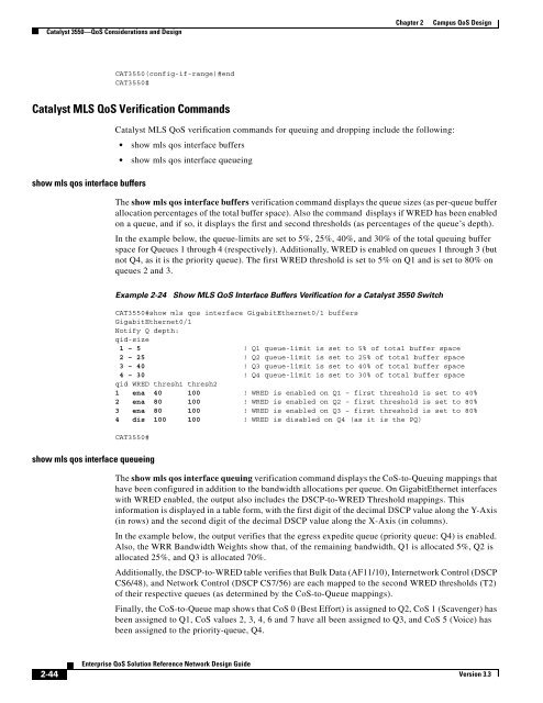
The show mls qos interface buffers verification command displays the queue sizes (as per-queue buffer<br />
allocation percentages of the total buffer space). Also the command displays if WRED has been enabled<br />
on a queue, and if so, it displays the first and second thresholds (as percentages of the queue’s depth).<br />
In the example below, the queue-limits are set to 5%, 25%, 40%, and 30% of the total queuing buffer<br />
space for Queues 1 through 4 (respectively). Additionally, WRED is enabled on queues 1 through 3 (but<br />
not Q4, as it is the priority queue). The first WRED threshold is set to 5% on Q1 and is set to 80% on<br />
queues 2 and 3.<br />
Example 2-24 Show MLS <strong>QoS</strong> Interface Buffers Verification for a Catalyst 3550 Switch<br />
CAT3550#show mls qos interface GigabitEthernet0/1 buffers<br />
GigabitEthernet0/1<br />
Notify Q depth:<br />
qid-size<br />
1 – 5 ! Q1 queue-limit is set to 5% of total buffer space<br />
2 – 25 ! Q2 queue-limit is set to 25% of total buffer space<br />
3 – 40 ! Q3 queue-limit is set to 40% of total buffer space<br />
4 – 30 ! Q4 queue-limit is set to 30% of total buffer space<br />
qid WRED thresh1 thresh2<br />
1 ena 40 100 ! WRED is enabled on Q1 – first threshold is set to 40%<br />
2 ena 80 100 ! WRED is enabled on Q2 – first threshold is set to 80%<br />
3 ena 80 100 ! WRED is enabled on Q3 – first threshold is set to 80%<br />
4 dis 100 100 ! WRED is disabled on Q4 (as it is the PQ)<br />
CAT3550#<br />
show mls qos interface queueing<br />
The show mls qos interface queuing verification command displays the CoS-to-Queuing mappings that<br />
have been configured in addition to the bandwidth allocations per queue. On GigabitEthernet interfaces<br />
with WRED enabled, the output also includes the DSCP-to-WRED Threshold mappings. This<br />
information is displayed in a table form, with the first digit of the decimal DSCP value along the Y-Axis<br />
(in rows) and the second digit of the decimal DSCP value along the X-Axis (in columns).<br />
In the example below, the output verifies that the egress expedite queue (priority queue: Q4) is enabled.<br />
Also, the WRR Bandwidth Weights show that, of the remaining bandwidth, Q1 is allocated 5%, Q2 is<br />
allocated 25%, and Q3 is allocated 70%.<br />
Additionally, the DSCP-to-WRED table verifies that Bulk Data (AF11/10), Internetwork Control (DSCP<br />
CS6/48), and <strong>Network</strong> Control (DSCP CS7/56) are each mapped to the second WRED thresholds (T2)<br />
of their respective queues (as determined by the CoS-to-Queue mappings).<br />
Finally, the CoS-to-Queue map shows that CoS 0 (Best Effort) is assigned to Q2, CoS 1 (Scavenger) has<br />
been assigned to Q1, CoS values 2, 3, 4, 6 and 7 have all been assigned to Q3, and CoS 5 (Voice) has<br />
been assigned to the priority-queue, Q4.<br />
Version 3.3


