EUTELSAT Systems Operations Guide - Lea
EUTELSAT Systems Operations Guide - Lea
EUTELSAT Systems Operations Guide - Lea

Create successful ePaper yourself
Turn your PDF publications into a flip-book with our unique Google optimized e-Paper software.
Issue 2.0<br />
<strong>EUTELSAT</strong>S.A.<br />
<strong>Systems</strong> <strong>Operations</strong> <strong>Guide</strong><br />
ESOG<br />
Volume I<br />
EARTH STATION VERIFICATION<br />
AND ASSISTANCE<br />
(ESVA)<br />
Module130
SYSTEMS OPERATIONS GUIDE<br />
Volume 1<br />
ESOG Module 130<br />
EARTH STATION VERIFICATION AND<br />
ASSISTANCE (ESVA)<br />
Issue 2.0 25-07-2000<br />
1. INTRODUCTION . . . . . . . . . . . . . . . . . . . . . . . . . . . . . . . . . . . . . . . . . . . . . . . . . 1<br />
2. ESVA REQUIREMENTS . . . . . . . . . . . . . . . . . . . . . . . . . . . . . . . . . . . . . . . . . . . 3<br />
3. TEST EQUIPMENT . . . . . . . . . . . . . . . . . . . . . . . . . . . . . . . . . . . . . . . . . . . . . . . 7<br />
4. SPACE SEGMENT ACCESS TEST. . . . . . . . . . . . . . . . . . . . . . . . . . . . . . . . . . . 9<br />
5. POLARIZATION ALIGNMENT . . . . . . . . . . . . . . . . . . . . . . . . . . . . . . . . . . . . 13<br />
6. EIRP (INCLUDING TRANSMIT GAIN). . . . . . . . . . . . . . . . . . . . . . . . . . . . . . 17<br />
7. TRANSMIT POLARIZATION DISCRIMINATION. . . . . . . . . . . . . . . . . . . . . 24<br />
8. TRANSMIT SIDELOBES. . . . . . . . . . . . . . . . . . . . . . . . . . . . . . . . . . . . . . . . . . 31<br />
9. G/T . . . . . . . . . . . . . . . . . . . . . . . . . . . . . . . . . . . . . . . . . . . . . . . . . . . . . . . . . . . . 39<br />
10. RECEIVE POLARIZATION DISCRIMINATION . . . . . . . . . . . . . . . . . . . . . . 47<br />
11. RECEIVE SIDELOBES (INCLUDING RECEIVE GAIN) . . . . . . . . . . . . . . . . 53<br />
Annex A. Request for ESVA Format . . . . . . . . . . . . . . . . . . . . . . . . . . . . . . . . . . . . . . . . . . 57<br />
Annex B. Questionnaire . . . . . . . . . . . . . . . . . . . . . . . . . . . . . . . . . . . . . . . . . . . . . . . . . . . . 61<br />
Annex C. List of Abbreviations . . . . . . . . . . . . . . . . . . . . . . . . . . . . . . . . . . . . . . . . . . . . . . 65<br />
Annex D. ESVA Contact Points . . . . . . . . . . . . . . . . . . . . . . . . . . . . . . . . . . . . . . . . . . . . . . 67<br />
Annex E. <strong>EUTELSAT</strong> Beacons . . . . . . . . . . . . . . . . . . . . . . . . . . . . . . . . . . . . . . . . . . . . . . 69<br />
Annex F. Frequency Plans . . . . . . . . . . . . . . . . . . . . . . . . . . . . . . . . . . . . . . . . . . . . . . . . . . 77<br />
Annex G. Measurement of Spurious Radiation . . . . . . . . . . . . . . . . . . . . . . . . . . . . . . . . . 119<br />
Annex H. Earth Station Alignment Verification . . . . . . . . . . . . . . . . . . . . . . . . . . . . . . . . 127
FOREWORD<br />
The <strong>EUTELSAT</strong> <strong>Systems</strong> <strong>Operations</strong> <strong>Guide</strong> (ESOG) is published to provide all <strong>EUTELSAT</strong> space<br />
segment users with information that is necessary for successful operation of earth stations within<br />
the <strong>EUTELSAT</strong> satellite system.<br />
The ESOG in its final form will consist of 2 Volumes. They contain, in modularised form, all the<br />
necessary details which are considered important for the operations of earth stations.<br />
Volume I concentrates on System Management and Policy aspects and is therefore primarily of<br />
interest to personnel engaged in these matters.<br />
Volume II is of direct concern to earth station staff who are directly involved in system operations,<br />
i.e. the initial line-up of satellite links between earth stations and the commissioning of earth<br />
stations for <strong>EUTELSAT</strong> services. The modules that are contained in this Volume relate to the<br />
services provided via <strong>EUTELSAT</strong> satellites.<br />
Regarding Issue 2.0 of Module 130:<br />
In view to the previous issue 1.1 (and DRAFT issue 2), this version includes the following<br />
enhancements:<br />
1. Antennae without angular readout (para. 8.2.2)<br />
2. More details of <strong>EUTELSAT</strong> beacons (Annex E)<br />
3. Measurement guidelines for spurious radiation (Annex G)<br />
Annex F has been updated and minor editorial changes were made to other chapters.<br />
The ESOG can now be obtained, apart from the printed version, in Acrobat format from the<br />
<strong>EUTELSAT</strong> Internet server:<br />
http://www.eutelsat.com/Satellite information/Technical & operational docs/Uplinking & Satcom<br />
Services/<strong>EUTELSAT</strong> <strong>Systems</strong> Operation <strong>Guide</strong> (ESOG).<br />
Paris, 25-07-2000
OVERVIEW ESOG MODULES<br />
VOLUME I<br />
<strong>EUTELSAT</strong> S.A. SYSTEM MANAGEMENT AND POLICIES<br />
Earth Station Standards. . . . . . . . . . . . . . . . . . . . . . . . . . . . . . . . . . . . . . . . . . . . . . . . . Module 100<br />
Earth Station Access and Approval Procedures . . . . . . . . . . . . . . . . . . . . . . . . . . . . . . Module 110<br />
Earth Station Type Approval. . . . . . . . . . . . . . . . . . . . . . . . . . . . . . . . . . . . . . . . . . . . . Module 120<br />
Earth Station Verification Assistance (ESVA) . . . . . . . . . . . . . . . . . . . . . . . . . . . . . . . Module 130<br />
Operational Management, Control, Monitoring & Coordination . . . . . . . . . . . . . . . . . Module 140<br />
Services and Space Segment Reservation. . . . . . . . . . . . . . . . . . . . . . . . . . . . . . . . . . . Module 150<br />
VOLUME II<br />
<strong>EUTELSAT</strong> S.A. SYSTEMS OPERATIONS AND PROCEDURES<br />
TV Handbook . . . . . . . . . . . . . . . . . . . . . . . . . . . . . . . . . . . . . . . . . . . . . . . . . . . . . . . . Module 210<br />
SMS Handbook . . . . . . . . . . . . . . . . . . . . . . . . . . . . . . . . . . . . . . . . . . . . . . . . . . . . . . . Module 220<br />
VSAT Handbook. . . . . . . . . . . . . . . . . . . . . . . . . . . . . . . . . . . . . . . . . . . . . . . . . . . . . . Module 230<br />
SKYPLEX Handbook. . . . . . . . . . . . . . . . . . . . . . . . . . . . . . . . . . . . . . . . . . . . . . . . . . Module 240<br />
DVB Television Handbook. . . . . . . . . . . . . . . . . . . . . . . . . . . . . . . . . . . . . . . . . . . . . . Module 250
page 1 EARTH STATION VERIFICATION AND ASSISTANCE (ESVA)<br />
1. INTRODUCTION<br />
ESOG Volume 1 Module 130 Issue 2.0, 25-07-2000<br />
1<br />
1<br />
0<br />
<strong>EUTELSAT</strong> approval procedures require the submission of technical earth<br />
station data to demonstrate compliance with the relevant specifications<br />
(ESOG Vol. I, Module 100 and Module 110 refer).<br />
In general, this can be achieved by the following means:<br />
<strong>EUTELSAT</strong> ESVA facilities.<br />
Non-<strong>EUTELSAT</strong> facilities such as:<br />
• test range, boresight tower, radiostar etc.,<br />
other satellite systems.<br />
Some combination of these facilities.<br />
The purpose of conducting verification tests is to prove that the earth station<br />
and/or associated equipment will comply in all respects with the mandatory<br />
performance characteristics as set forth in the relevant specifications.<br />
Verification testing involving the use of a <strong>EUTELSAT</strong> satellite shall be<br />
conducted in cooperation with the <strong>EUTELSAT</strong> ESVA facility and/or a<br />
qualified corresponding earth station, under the direction of the <strong>EUTELSAT</strong><br />
CSC.<br />
ESVA testing, which is an efficient and inexpensive alternative to most other<br />
methods, may be required upon request from <strong>EUTELSAT</strong> or the earth station<br />
owner. The ESVA testing may generally be required:<br />
for new earth stations prior to commencement of service,<br />
for existing earth stations after major modifications (especially of the RF<br />
front end).<br />
Typical parameters which can be measured using a <strong>EUTELSAT</strong> satellite and<br />
are included in the standard program presented in this Module are:<br />
earth station EIRP,<br />
transmit gain,<br />
transmit sidelobes,<br />
transmit polarisation isolation,<br />
receive gain,<br />
G/T,<br />
receive polarisation isolation,<br />
receive sidelobe patterns.
page 2 EARTH STATION VERIFICATION AND ASSISTANCE (ESVA)<br />
The above measurements are generally conducted between an <strong>EUTELSAT</strong><br />
reference station and a distant earth station under test via the <strong>EUTELSAT</strong><br />
space segment. This enables testing of a given station at it’s true, operational<br />
configuration. For small earth stations (aperture
page 3 EARTH STATION VERIFICATION AND ASSISTANCE (ESVA)<br />
2<br />
2<br />
2. ESVA REQUIREMENTS<br />
This section includes the conditions which ensure smooth implementation of<br />
ESVA, namely:<br />
prevention of interference to existing traffic,<br />
consistency of measurement results,<br />
efficient coordination of testing.<br />
The rules given hereafter apply to all ESVA activities including full scale<br />
ESVA programmes or parts of it and repetitions.<br />
2.1. Earth Station Preparation<br />
The correct function of all relevant earth station equipment must be verified<br />
by preliminary in-station testing. Thus avoiding delay of ESVA and<br />
interference to existing traffic during the initial space segment access. As far<br />
as possible, the in-station test shall prove compliance of the equipment with<br />
the <strong>EUTELSAT</strong> specification. Additional parameters which are required for<br />
ESVA such as:<br />
antenna slew speed for azimuth and elevation,<br />
power meter coupling factor and post coupler loss for each TX chain,<br />
receive coupling factor and receive feed loss if applicable<br />
shall be measured during the preparational phase and results shall be<br />
communicated to <strong>EUTELSAT</strong>.<br />
Before the commencement of the ESVA, the SUT must be already configured<br />
for the forthcoming measurements (Figure 4.1 refers). The station shall<br />
acquire and track the satellite foreseen for testing and the equipment shall be<br />
set to parameters defined in the <strong>EUTELSAT</strong> test plan.<br />
To eliminate eventual problems at this stage, it is strongly recommended to<br />
perform a G/T and a receive sidelobe pattern test, using the satellite beacon.<br />
ESOG Volume 1 Module 130 Issue 2.0, 25-07-2000
page 4 EARTH STATION VERIFICATION AND ASSISTANCE (ESVA)<br />
2.2. Test Coordination<br />
Planning of ESVA activities is based on the initial request for ESVA<br />
forwarded by the relevant telecommunications entity (i.e. Signatory or<br />
DATE). For new earth stations, this request is made by completion of<br />
paragraph 6 of the "APPLICATION FOR APPROVAL TO ACCESS THE<br />
<strong>EUTELSAT</strong> SPACE SEGMENT" (ESOG Module 110, Annex 1). The<br />
format of Annex 1 to this Module may be used for already approved stations.<br />
An advance notice of normally 4 weeks prior to the tentative ESVA date,<br />
should be given to ensure smooth implementation. <strong>EUTELSAT</strong> issues a test<br />
plan which includes the confirmation of the availability of the ESVA facility<br />
(i.e. space segment and reference station). It must be born in mind that due to<br />
operational needs, the test plan may be subject to changes at any time on short<br />
notice. The test plan contains the time schedule, technical and geographical<br />
parameters, contact points and notes required for preparation and execution of<br />
the subject test.<br />
Immediately after conclusion of testing, the <strong>EUTELSAT</strong> Reference Station<br />
transmits a provisional test report to the test manager of the station under test.<br />
This provisional report provides a summary of all test results. All data is<br />
subject to confirmation by <strong>EUTELSAT</strong> who will issue the final test report<br />
usually within 4 weeks following test conclusion.<br />
This final report comprises results and parameters in detail and, will be<br />
forwarded to the relevant telecommunications entity who initially requested<br />
the subject ESVA.<br />
2.3. Space Segment Access<br />
Prior to commencement of any test programme, the Station Under Test (SUT)<br />
must contact the <strong>EUTELSAT</strong> Reference Station (ERS). The reference station<br />
will then coordinate with the <strong>EUTELSAT</strong> CSC the forthcoming test<br />
activities. The reference station must obtain the approval of the CSC for space<br />
segment access before the start of testing and report to the CSC when testing<br />
is terminated or in case of significant interruptions.<br />
ESOG Volume 1 Module 130 Issue 2.0, 25-07-2000
page 5 EARTH STATION VERIFICATION AND ASSISTANCE (ESVA)<br />
Furthermore, each space segment access by a station under test must be<br />
endorsed by the <strong>EUTELSAT</strong> Reference Station. When transmitting, the<br />
Station Under Test must maintain contact with the reference station during<br />
ALL times. In particular, the SUT must ensure permanent presence of staff at<br />
the phone to guarantee instant reaction on ERS directives. If the<br />
communication link fails, the Station Under Test must immediately CEASE<br />
transmissions and attempt to re-establish contact with the reference station. It<br />
is therefore essential, that suitable telephone equipment be available and<br />
accessible at all relevant sites (e.g.: antenna hub, control room etc.)<br />
throughout testing. The appropriate phone(s) must be authorized for<br />
international connections and shall preferably be equipped with a<br />
loudspeaker. The detailed procedures compulsory to each space segment<br />
access are prescribed in paragraph 4.1 of this document.<br />
2.4. Weather Conditions<br />
Atmospherical attenuation and wind may considerably degrade the accuracy<br />
of measurements. It is therefore preferable to conduct ESVA testing during<br />
clear sky conditions where light windspeeds are not exceeded. If, due to<br />
operational needs, testing has to be performed during deteriorated weather<br />
conditions, special consideration will be given to evaluation of results. In case<br />
of discrepancies, partial or complete repetition of the test programme will be<br />
agreed.<br />
2.5. Antenna Alignment<br />
All ESVA tests are based on the perfect initial alignment of the antenna under<br />
test. Great care must be taken by the Station Under Test when optimizing the<br />
antenna pointing i.e. peaking.<br />
Peaking must be performed initially, i.e. prior to testing,<br />
1. after each antenna movement (e.g. during G/T, antenna sidelobe<br />
measurements etc...),<br />
2. after interruption of the test programme,<br />
3. before each measurement during transmissions via satellites in inclined<br />
orbit.<br />
The Station Under Test must ensure that optimized pointing is achieved<br />
during all measurements. On request, the reference station will provide<br />
assistance and guide the Station Under Test.<br />
ESOG Volume 1 Module 130 Issue 2.0, 25-07-2000
page 6 EARTH STATION VERIFICATION AND ASSISTANCE (ESVA)<br />
2.6. Check List<br />
Completion of the following check-list by the Station Under Test, before the<br />
start of an ESVA activity will prevent delays.<br />
Earth Station equipment functions compliant to specifications<br />
Antenna, drive and tracking system<br />
HPA<br />
LNA (LNB, LNC)<br />
Up and Down-Converters<br />
Station control and waveguide switching<br />
TX chains have been checked for spurious emissions<br />
Test equipment is available, calibrated and warm-up period<br />
respected<br />
RF synthesizer (frequency drift measured)<br />
RF power meter (auto-zero, calibration factor set)<br />
Spectrum Analyser (calibration procedure completed)<br />
Plotter (connected, calibrated)<br />
TX power meter coupling factors and post coupler losses measured<br />
for each TX-chain, results sent to <strong>EUTELSAT</strong><br />
Antenna slew speed measured for azimuth and elevation, results sent<br />
to <strong>EUTELSAT</strong><br />
Satellite as per test plan acquired, antenna pointing optimized<br />
(peaking)<br />
Polarization alignment optimized<br />
Appropriate means for communication during the test are available<br />
–and optional:<br />
G/T and antenna RX-pattern measured via satellite beacon<br />
ESOG Volume 1 Module 130 Issue 2.0, 25-07-2000
page 7 EARTH STATION VERIFICATION AND ASSISTANCE (ESVA)<br />
3. TEST EQUIPMENT<br />
ESOG Volume 1 Module 130 Issue 2.0, 25-07-2000<br />
3<br />
3<br />
The measurement equipment which must be available at the Station Under<br />
Test during ESVA, is summarized hereafter. Prior to the start of ESVA, the<br />
station operator shall ensure that all test equipment:<br />
functions correctly,<br />
warm-up periods are respected,<br />
calibration procedures have been carried out correctly.<br />
For completion of test records, the test equipment types shall be reported to<br />
<strong>EUTELSAT</strong>.<br />
3.1. RF Power Meter<br />
The RF power meter is required for the measurement of the transmit power<br />
and calibration of the station EIRP. At SUT equipped for pilot injection, the<br />
power meter is furthermore required for measurement of the pilot level.<br />
Generally, the dynamic range of the power sensor should be dimensioned to<br />
include the full range of transmit power required during operations and<br />
ESVA. Before measurements, the operator shall set the appropriate<br />
calibration factor and execute an "Auto-Zero" cycle to ensure accurate results.<br />
Examples 1 : Hewlett Packard 435B; 436A; 437A; 438A<br />
Hewlett Packard EPM 442A<br />
Rhode & Schwarz NRVS<br />
Gigatronix 8541, 8542<br />
Marconi RF Power Meter 6960B<br />
3.2. RF Spectrum Analyser<br />
The spectrum analyser is required for execution of the space segment access<br />
test, the measurement of the G/T ratio and the antenna receive sidelobe<br />
pattern. Furthermore, it is used for monitoring of the receive frequency range<br />
and the HPA output. To facilitate the G/T measurement, it is preferable to use<br />
an analyser which permits a direct noise level readout (noise marker). The RF<br />
and IF frequency bands of the station under test should be covered by the<br />
analyser.
page 8 EARTH STATION VERIFICATION AND ASSISTANCE (ESVA)<br />
Examples 1 : Hewlett Packard 8566 A/B<br />
Hewlett Packard 8562 A<br />
Wandel & Goltermann SNA-23<br />
Ronde & Schwarz FSEM or FSEK series<br />
Ronde & Schwarz FSIQ 26 or FSP30<br />
Aritsu MS 2802A<br />
A suitable plotter/recorder is necessary for documentation of the antenna<br />
pattern test results.<br />
3.3. Signal Source<br />
For the assessment of transmit parameters, a stable signal source is required<br />
at the station under test. To prevent interference when testing is conducted via<br />
transponders bearing traffic, to obtain a maximum dynamic range and<br />
accuracy, the frequency drift, residual modulation and level variation must be<br />
kept at a minimum.<br />
The short term frequency drift measured at RF level (e.g. 14 GHz), should be<br />
less than 10 Hz per 30 minutes (typical figure: 5 x 10 -10 /day ageing rate).<br />
Therefore, a synthesized source is required for generation of the test signal.<br />
Alternatives like the operational modulator require prior endorsement by<br />
<strong>EUTELSAT</strong> and should be considered only in exceptional case:<br />
Examples 1 : Hewlett Packard 8672 A<br />
Hewlett Packard 8673 A<br />
Hewlett Packard 8341 B<br />
Rhode & Schwarz SMP22<br />
1. The test equipment list is not exhaustive. Alternative test sets e.g. of other manufacturers<br />
may be suitable to accomplish ESVA testing<br />
ESOG Volume 1 Module 130 Issue 2.0, 25-07-2000
page 9 EARTH STATION VERIFICATION AND ASSISTANCE (ESVA)<br />
4<br />
4<br />
4. SPACE SEGMENT ACCESS TEST<br />
4.1. Test Objectives<br />
1. To ensure the correct alignment with parameters prescribed in the<br />
<strong>EUTELSAT</strong> test plan.<br />
2. To prevent any interference to existing services.<br />
3. To evaluate basic carrier parameters as frequency drift and EIRP<br />
fluctuation in order to estimate possible impairments to test results and to<br />
adapt instrument settings at ERS accordingly.<br />
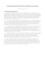
4.2. Principle<br />
Initially, the ERS transmits a marker carrier which shall be identified by the<br />
SUT to prove correct pointing. Upon authorization by the ERS, the SUT<br />
transmits at low EIRP. The ERS will check value and fluctuation of carrier<br />
level and frequency.<br />
PLOTTER<br />
MODULATOR<br />
IF / RF<br />
SPECTRUM<br />
ANALYSER<br />
DEMODULATOR<br />
UP -<br />
CONVERTER HPA TX - COUPLER<br />
RF<br />
IF<br />
RF<br />
SYNTHESIZER<br />
TX - Tests<br />
RF<br />
IF<br />
RF<br />
POWER METER<br />
In - Station<br />
Pilot Injection *<br />
DOWN -<br />
CONVERTER LNA RX - COUPLER<br />
TX - EIRP<br />
MONITOR POINT<br />
Figure 4.1 : SUT Configuration during ESVA<br />
ANTENNA<br />
Test Equipment<br />
Equiqment<br />
E/ E/S S Equipment<br />
Equiqment<br />
Not Mandatory<br />
ESOG Volume 1 Module 130 Issue 2.0, 25-07-2000
page 10 EARTH STATION VERIFICATION AND ASSISTANCE (ESVA)<br />
4.3. Step-by-Step Procedure<br />
A. Acquisition of Satellite<br />
Step 1: Upon successful completion of the independent in-station tests as described<br />
under para. 2.1 above and PRIOR to the transmission of ANY signal, the<br />
SUT shall identify, acquire and track the specified satellite.<br />
Step 2: SUT set the polarization angle according to the parameter provided in the<br />
<strong>EUTELSAT</strong> test plan. For further optimization, SUT shall monitor the crosspolar<br />
component of the satellite beacon signal. The, SUT shall slowly rotate<br />
the polarization plane until the level reaches a minimum.<br />
Note: Where this procedure is not applicable (e.g. for transmission on X polarization<br />
from SUT equipped with a 2-port feed), another suitable signal on the satellite<br />
may be used.<br />
B. Access Coordination<br />
Step 3: Immediately prior to the scheduled commencement of ESVA (i.e. ~ 5<br />
minutes) the SUT shall establish and maintain phone contact with ERS. SUT<br />
shall communicate sky and wind conditions and information on all details<br />
which may impair testing.<br />
Step 4: ERS ensure that the allocated frequency range is free of traffic.<br />
Step 5: ERS shall contact the <strong>EUTELSAT</strong> CSC to obtain authorization for space<br />
segment access. If required, CSC arrange for change of satellite configuration<br />
on request of ERS.<br />
Step 6: In accordance with parameters of the <strong>EUTELSAT</strong> test plan, ERS transmit a<br />
marker carrier.<br />
Step 7: On request of ERS, SUT monitor the allocated down-link frequency range.<br />
SUT reconfirm presence of the marker carrier to ERS.<br />
Step 8: ERS double-checks identification of marker carrier by SUT. Proceed to Step<br />
9 only if identification is affirmative.<br />
C. Transmission by SUT<br />
Step 9: Under direction of the ERS, SUT transmit a carrier at the assigned frequency<br />
and EIRP. (The initial EIRP is in general in the order of 50 dBW and it must<br />
never exceed 55 dBW).<br />
Note: The SUT must CEASE transmissions immediately if the communications<br />
link to the ERS fails or if the presence of staff at the SUT phone is<br />
interrupted. This rule applies to this and all following tests where the SUT<br />
transmits.<br />
Step 10: SUT notify the ERS of the activation of its carrier.<br />
ESOG Volume 1 Module 130 Issue 2.0, 25-07-2000
page 11 EARTH STATION VERIFICATION AND ASSISTANCE (ESVA)<br />
Step 11: If the ERS does not detect the carrier under test within the allocated frequency<br />
range, the SUT shall CEASE transmissions. The SUT shall again verify its<br />
set-up on:<br />
correct satellite acquisition,<br />
polarization plane alignment,<br />
transmit frequency and<br />
transmit EIRP<br />
and return to Step 8.<br />
Step 12: ERS check carrier frequency, EIRP and polarization and request corrections<br />
if necessary.<br />
Step 13: SUT monitor the receive level of its own transmitted carrier. ERS request<br />
SUT to slew SUT antenna first in azimuth and then in elevation to reconfirm<br />
correct pointing.<br />
Step 14: SUT report TX power meter reading to ERS and maintain frequency setting<br />
throughout following tests.<br />
Step 15: ERS monitor short term (~ 10 minutes) fluctuation of frequency and EIRP of<br />
carrier under test.<br />
ESOG Volume 1 Module 130 Issue 2.0, 25-07-2000
page 12 EARTH STATION VERIFICATION AND ASSISTANCE (ESVA)<br />
4.4. Example for Spectrum Analyser Setting<br />
hp<br />
1 dB/<br />
Reference level : As applicable<br />
Attenuator : As applicable<br />
Scale : 1 dB/Division<br />
Centre frequency : SUT down-link frequency as per test plan<br />
(11 or 12 GHz range)<br />
Span : 200 Hz<br />
Resolution bandwidth : Auto<br />
Video bandwidth : Auto<br />
Video averaging : OFF<br />
Sweep time : Auto<br />
Marker noise : OFF<br />
D-Marker : OFF<br />
Trace : Clear write A<br />
Max. Hold B<br />
Display line : OFF<br />
REF - 45.0 dBm ATTEN 10 dB<br />
CENTER 11.107 000 898 GHz<br />
RES BW 10 Hz VBW 30 Hz<br />
SPAN 200 Hz<br />
SWP 6.00 sec<br />
Figure 4.2 : Spectrum Analyser Display at ERS during Space Segment Access<br />
Test (Verification of frequency stability)<br />
ESOG Volume 1 Module 130 Issue 2.0, 25-07-2000
page 13 EARTH STATION VERIFICATION AND ASSISTANCE (ESVA)<br />
5<br />
5<br />
5. POLARIZATION ALIGNMENT<br />
5.1. Test Objectives<br />
To accomplish optimum alignment of the polarization plane of the SUT<br />
antenna with the receive antenna of the satellite, in order to guaranty accurate<br />
ESVA measurement results.<br />
For SUT equipped with 4-port feed, to evaluate orthogonality of transmit<br />
polarization planes (X and Y).<br />
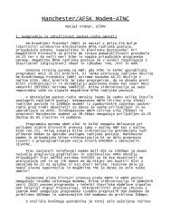
5.2. Principle<br />
The SUT transmits a carrier via the co-polar channel while the ERS monitors<br />
the residual carrier level in the cross-polar channel. Under control of the ERS,<br />
the SUT slowly rotates its polarization plane. The ERS records the variation<br />
of the cross-polar level and guides the SUT to the angular position where the<br />
minimum level is detected (nulling).<br />
The following configurations must be considered:<br />
1. the down-link frequency bands of the co-polar and cross-polar channel are<br />
different.<br />
2. The down-link frequency bands are identical but the co-polar satellite<br />
channel is switched OFF.<br />
3. The down-link frequency bands are identical and the co-polar channel is<br />
ON:<br />
a) The co-polar channel is set to minimum gain and the cross-polar<br />
channel is set to maximum gain.<br />
b) Gain settings of one or both channels may not be changed.<br />
To avoid influence caused by the down-link, the polarization alignment is<br />
performed in configuration 1) or 2) above. The ERS will apply additional<br />
precautions in the evaluation of recorded data in case of configurations 3).<br />
For SUT equipped with a 4-port feed, and in order to verify the orthogonality,<br />
the alignment procedure is executed via both polarizations (X and Y). The<br />
angle indications for the optimum positions are read for X and Y polarization<br />
and then compared.<br />
ESOG Volume 1 Module 130 Issue 2.0, 25-07-2000
page 14 EARTH STATION VERIFICATION AND ASSISTANCE (ESVA)<br />
Cross-polar Level [dB]<br />
TX Polarization Angle Tilt Relative to Satellite RX Antenna [°]<br />
Figure 5.1 : Cross-polar Signal Level as Function of Polarization Plane<br />
Alignment<br />
Figure 5.2 : Schematic Representation of Polarization Alignment<br />
ESOG Volume 1 Module 130 Issue 2.0, 25-07-2000<br />
-20<br />
-30<br />
-40<br />
-50<br />
-60<br />
-70<br />
Theoretical<br />
Actual<br />
-5 -3 -1 1 3 5<br />
C<br />
T<br />
X T X SR<br />
Satellite<br />
receive<br />
antenna<br />
C<br />
T<br />
C<br />
T<br />
X T + X SR<br />
X T<br />
Station<br />
under<br />
Test (SUT)<br />
Co - polar XDR OFF or Down - link<br />
frequency different to cross - polar XDR<br />
X - Polar XDR ON<br />
C T : Co - polar signal<br />
X T : Station under Test - X - polar component<br />
X SR : Satellite receive - X - polar component<br />
<strong>EUTELSAT</strong><br />
Reference<br />
Station (ERS)<br />
XSR XT X SR<br />
X T<br />
X T + X SR<br />
XSR XT Satellite<br />
transmit<br />
antenna
page 15 EARTH STATION VERIFICATION AND ASSISTANCE (ESVA)<br />
5.3. Step-by-Step Procedure<br />
Step 1: If required, CSC arrange for change of satellite configuration on request of<br />
ERS.<br />
Step 2: SUT set antenna tracking system to manual mode.<br />
Step 3: Under direction of ERS, SUT transmit a carrier at the frequency as established<br />
during the Satellite Access Test and set the EIRP as per test plan.<br />
Step 4: ERS record the level of the cross-polar component of the carrier under test.<br />
Step 5: In coordination with the ERS, SUT rotate slowly the polarization plane in the<br />
following way:<br />
1. Rotate towards the anti-clockwise limit. (e.g.: −5° relative to start<br />
position).<br />
2. Rotate via the optimum to the clockwise limit. (e.g.: +5° relative to start<br />
position).<br />
Note: Values of angles are positive if the rotation is clockwise as seen from the earth<br />
station towards the satellite.<br />
Step 6: ERS guide SUT to acquire the optimum position (i.e. where polarization<br />
plane of SUT and satellite receive antenna match and a minimum in crosspolar<br />
level is observed).<br />
Step 7: SUT secure feed position. ERS verify that the optimum is maintained.<br />
Step 8: SUT report the polarization angle indication to the ERS. If the SUT is not<br />
equipped with indicators, the feed position shall be marked.<br />
ESOG Volume 1 Module 130 Issue 2.0, 25-07-2000
page 16 EARTH STATION VERIFICATION AND ASSISTANCE (ESVA)<br />
5.4. Example for Spectrum Analyser Setting<br />
Reference level : As applicable<br />
Attenuator : As applicable<br />
Scale : 5 dB/Division<br />
Centre frequency : SUT down-link frequency as per test plan<br />
(11 or 12 GHz range)<br />
Span : 0 Hz<br />
Resolution bandwidth : 100 Hz<br />
Video bandwidth : 3 Hz<br />
Sweep time : 100 s or as appropriate<br />
Marker noise : OFF<br />
∆-Marker : Disabled<br />
Trace : Clear write A<br />
Display line : Set to minimum<br />
T<br />
Freq<br />
Amptd<br />
Marker<br />
BW Swp<br />
Traces<br />
State<br />
Misc<br />
AL -17.88 dBm<br />
ATTEN 0 dB<br />
5.00 dB / DIV<br />
CENTER 11.479 005 150 GHz<br />
RB 100 Hz VB 3.00 Hz<br />
SPAN 0 Hz<br />
ST 40.00 sec<br />
MENU<br />
RES BW<br />
AutoMan<br />
VID BW<br />
AutoMan<br />
SWPTIME<br />
AutoMan<br />
CONT<br />
SWEEP<br />
SINGLE<br />
SWEEP<br />
VID AVG<br />
On Off<br />
Figure 5.3 : Spectrum Analyser Display during Polarization Plane Alignment<br />
ESOG Volume 1 Module 130 Issue 2.0, 25-07-2000
page 17 EARTH STATION VERIFICATION AND ASSISTANCE (ESVA)<br />
6<br />
6<br />
6. EIRP (INCLUDING TRANSMIT GAIN)<br />
6.1. Test Objectives<br />
1. To reconfirm the SUT EIRP calibration prior to commencement of<br />
operations.<br />
2. To assess the linearity of the EIRP indication at the SUT.<br />
3. To evaluate the transmit gain of the antenna at the SUT.<br />
4. To measure the maximum EIRP capability of the SUT.<br />
6.2. Principle<br />
6.2.1. Power Balance<br />
The EIRP measurement is based on the up-link power balance technique<br />
where the EIRP of the SUT is compared against an accurately calibrated EIRP<br />
radiated from the ERS. Corrections for the satellite antenna receive gain (offaxis<br />
loss), path loss and atmospherical loss due to the distant location of both<br />
stations are applied to obtain the value of the SUT EIRP. To minimize the<br />
influence of amplitude-frequency response of the satellite transponder and<br />
ERS, the difference of carrier frequencies of SUT and ERS is small (generally<br />
< 100 kHz). Carrier levels of both SUT and ERS are equal or differ by no<br />
more than 0.2 dB to avoid inaccuracies due to the non-linearity of the satellite<br />
TWT.<br />
The following formula applies:<br />
EIRP SUT = EIRP ERS<br />
+ (L oa,SUT − L oa,ERS )<br />
+ (L at,SUT − L at,ERS )<br />
+ (l fs,SUT − L fs,ERS ) − ∆<br />
where: L oa : Off-axis Loss [dB]<br />
L fs : Free space Loss [dB]<br />
L at : Atmospheric Loss [dB]<br />
∆ : Small difference between EIRP of carriers [dB]<br />
∆ is positive when: EIRP SUT < EIRP ERS<br />
∆ is small when: |∆|< 0.2 dB<br />
ESOG Volume 1 Module 130 Issue 2.0, 25-07-2000<br />
(1)
page 18 EARTH STATION VERIFICATION AND ASSISTANCE (ESVA)<br />
L at is measured at the ERS by radiometer during the test. For SUT where no<br />
radiometer is available, 0.3 dB shall be assumed for clear sky conditions.<br />
The values of free-space loss (L fs ) and off-axis loss (L oa ) will be indicated in<br />
the relevant <strong>EUTELSAT</strong> test plan.<br />
6.2.2. EIRP Calibration<br />
At power balance condition, the SUT reads the transmit power meter. This<br />
value which corresponds to a (now) accurately known EIRP, shall be noted<br />
and used as reference for future operations.<br />
In cases where the power reading during operations will not be derived from<br />
the same test point, it is essential to include the operational test point in the<br />
calibration procedure.<br />
6.2.3. Linearity of EIRP Indication<br />
Corresponding EIRP [dBW]<br />
EIRP calibration is repeated at several (e.g. 4) different EIRP levels. The<br />
range shall include the future operational EIRP of the SUT. It shall thus<br />
provide a reliable base for determination of any EIRP value required during<br />
forthcoming SUT operations.<br />
Title<br />
75<br />
70<br />
65<br />
60<br />
55<br />
50<br />
Measured EIRP [dBW]<br />
Mean<br />
Max. EIRP Capability of E/S<br />
-25 -20 -15 -10 -5 0<br />
Figure 6.1 : Linearity of TX Power Indication<br />
ESOG Volume 1 Module 130 Issue 2.0, 25-07-2000
page 19 EARTH STATION VERIFICATION AND ASSISTANCE (ESVA)<br />
6.2.4. Transmit Gain<br />
At known station EIRP the antenna TX gain of the SUT may be calculated.<br />
During ESVA preparation, TX power meter coupling factor and loss between<br />
TX coupler and antenna flange (or interface where antenna gain is defined)<br />
have to be obtained by in-station measurements.<br />
Signal Source HPA TX - Coupler<br />
(12.9)14.0 - 14.5 = 14.5 GHz(18.4)<br />
GHz<br />
Post Coupler<br />
losses<br />
Figure 6.2 : Schematic Diagram of SUT TX-Chain<br />
Using the value of EIRP SUT from equation (1) above, the TX gain is given by:<br />
where: Pm : Tx power meter reading [dBm]<br />
CTX : Tx coupling factor [dB]<br />
LTX : Post coupler Losses [dB]<br />
30 : Conversion dBW ⇒ dBm [dB]<br />
To appreciate the measurement result, it is compared to the expected value<br />
which may be computed as follows:<br />
where: G : Antenna gain [dBi]<br />
η : Efficiency (assumed at 0.65) [1]<br />
a, b : Major, minor axis of antenna<br />
reflector aperture<br />
[m]<br />
f<br />
c<br />
: Frequency<br />
: Speed of light (i.e 3 x 10<br />
[Hz]<br />
8 G 10Log10 η a b ⎛π⋅f --------- ⎞<br />
⎝ c ⎠<br />
) [m/s]<br />
2<br />
=<br />
⎛<br />
⎝<br />
⋅ ⋅ ⋅ ⎞<br />
⎠<br />
ESOG Volume 1 Module 130 Issue 2.0, 25-07-2000<br />
C TX<br />
Pm<br />
TX - Powermeter<br />
L TX<br />
G TX = EIRP SUT − P m + 30 − C TX + L TX<br />
G TX EIRPSUT<br />
(2)<br />
(3)
page 20 EARTH STATION VERIFICATION AND ASSISTANCE (ESVA)<br />
6.2.5. Maximum EIRP Capability of SUT<br />
Under close control of the ERS, the SUT increases its TX EIRP to the<br />
maximum value defined as per test plan or until the saturation of the SUT<br />
HPA, which ever is reached first. If applicable, 2 HPAs and phase combiner<br />
shall be used during this test. The ERS conducts a power balance and logs the<br />
maximum EIRP capability of the SUT as reference for <strong>EUTELSAT</strong> records.<br />
ESOG Volume 1 Module 130 Issue 2.0, 25-07-2000
page 21 EARTH STATION VERIFICATION AND ASSISTANCE (ESVA)<br />
6.3. Step-by-Step Procedure<br />
A. Preparation<br />
Step 1: SUT forward the following information to <strong>EUTELSAT</strong> prior to<br />
commencement of ESVA:<br />
Type of feed (2-port, 4-port).<br />
No of TX-chains.<br />
Coupling factor (C TX ) for each TX chain.<br />
Post coupling Loss (LTX ) for each TX chain.<br />
Step 2: SUT set appropriate calibration factor of TX power meter and conduct an<br />
"Auto ZERO" cycle.<br />
B. Power Balance<br />
Step 3: If required, CSC arrange for change of transponder gain setting on request of<br />
ERS. ERS transmits the reference carrier at the frequency and EIRP as<br />
specified by the ESVA test plan.<br />
Step 4: SUT adjust the EIRP setting to obtain the value specified in the ESVA test<br />
plan. Under the direction of the ERS, SUT commence transmission at the<br />
frequency established during the Satellite Access Test.<br />
Step 5: If necessary, SUT adjust the EIRP under control of ERS to balance the<br />
reference carrier. The difference in level of both carriers as monitored by the<br />
ERS shall not exceed 0.2 dB.<br />
Step 6: ERS confirm balance condition.<br />
Step 7: SUT read the TX power meter and report the value to ERS.<br />
C. Linearity<br />
Step 8: If required by the test plan, ERS increase the EIRP of the reference carrier.<br />
Under control of ERS, SUT increase the EIRP of the carrier under test.<br />
Step 9: Repeat Steps 5 through 7 for each EIRP level to be calibrated.<br />
Note: In general the EIRP calibration is performed for the following levels:<br />
1. Start EIRP.<br />
2. Start EIRP − 5 dB.<br />
3. Start EIRP − 10 dB.<br />
4. Start EIRP − 15 dB.<br />
The start EIRP is specified in the ESVA test plan.<br />
D. Maximum EIRP Capability<br />
Step 10: Carry out this step only if required by the ESVA test plan, otherwise proceed<br />
to Step 12.<br />
ESOG Volume 1 Module 130 Issue 2.0, 25-07-2000
page 22 EARTH STATION VERIFICATION AND ASSISTANCE (ESVA)<br />
Step 11: Under close control of the ERS, SUT increase slowly the EIRP. The increase<br />
shall in no case exceed the limits given in the ESVA test plan to avoid<br />
interference to traffic or over saturation of the transponder. Below the<br />
specified limits, the SUT EIRP may be increased until the SUT HPA or in<br />
case of phase combiner, the two SUT HPAs are saturated. SUT report the TX<br />
power reading to ERS. If the SUT Tx chain is equipped with several couplers,<br />
the calibration is performed using the coupler which is the nearest to the<br />
antenna feed. For cross-reference, at least 1 measurement shall be performed<br />
for each Tx chain using another coupler(s) (e.g. HPA RF power meter).<br />
Step 12: If the SUT EIRP capability is superior to the limit stated as per test plan, the<br />
ERS will request to commute the SUT TX-chain to dummy load and/or to depoint<br />
the SUT antenna far off the geostationary arc. Then, the SUT increases<br />
its power to its maximum. The corresponding powermeter reading is<br />
communicated to the ERS, which will compute the maximum SUT EIRP<br />
capability. The SUT reduces its EIRP to the nominal level and ceases<br />
transmissions. To proceed with testing, the SUT re-acquires the satellite as<br />
previously defined.<br />
Step 13: From the results of the previous power balance, ERS evaluate the maximum<br />
EIRP capability of the SUT and the SUT antenna TX gain, and if available,<br />
other power indications (e.g. output-power display of HPA).<br />
ESOG Volume 1 Module 130 Issue 2.0, 25-07-2000
page 23 EARTH STATION VERIFICATION AND ASSISTANCE (ESVA)<br />
6.4. Example for Spectrum Analyser Settings<br />
1 dB /<br />
SAMPLE<br />
VID AVG<br />
Reference level : As applicable<br />
Attenuator : As applicable<br />
Scale : 1 dB/Division<br />
Centre frequency : SUT down-link frequency as per test plan<br />
(11 or 12 GHz range)<br />
Span : 200 kHz<br />
Resolution bandwidth : 30 kHz<br />
Video bandwidth : Auto<br />
Video average : 20<br />
Sweep time : Auto<br />
Marker noise : OFF<br />
Marker : Peak search<br />
∆-Marker : ∆-peak search<br />
Trace : Clear write A<br />
Display line : OFF<br />
REF -15.0 dBm ATTEN 10 dB<br />
Figure 6.3 : Spectrum Analyser Display during Power Balance<br />
MKR -59.2 kHz<br />
-0.13 dB<br />
CENTER 12.708 261 GHz SPAN 20<br />
RES BW 30 kHz VBW 100 Hz SWP 500 msec<br />
ESOG Volume 1 Module 130 Issue 2.0, 25-07-2000
page 24 EARTH STATION VERIFICATION AND ASSISTANCE (ESVA)<br />
7<br />
7<br />
0<br />
7. TRANSMIT POLARIZATION<br />
DISCRIMINATION<br />
7.1. Objectives<br />
To measure the transmit polarization isolation of the Station Under Test at<br />
optimized TX polarization alignment. The measurement is carried out at<br />
boresight and at 8 samples within the 1 dB contour of the co-polar antenna TX<br />
pattern.<br />
In case of non-orthogonal polarization planes, the operational XPD will be<br />
lower than measured during ESVA.<br />
7.2. Principle<br />
To measure the EIRP of the SUT, a power balance is carried out via the copolar<br />
channel. Then, the ERS transmits a reference carrier (e.g. 20, 30 or 40<br />
dB below the co-polar level) via the cross-polar transponder. From the<br />
difference in level of the reference carrier and the cross-polar component of<br />
the carrier under test, the transmit XPD of the SUT is computed. Then in order<br />
to verify the performance within the co-polar -1 dB TX contour, the SUT<br />
antenna is depointed in azimuth and elevation as described in the figure below<br />
- EAST<br />
counter-clock-wise<br />
CCW<br />
WEST +<br />
Figure 7.1 : Antenna Depointing Sequence during XPD Measurements<br />
ESOG Volume 1 Module 130 Issue 2.0, 25-07-2000<br />
+ UP<br />
- DOWN<br />
clock-wise<br />
CW
page 25 EARTH STATION VERIFICATION AND ASSISTANCE (ESVA)<br />
The angular increment for antennas with circular aperture may be estimated<br />
by the following expression:<br />
AI =<br />
3.978<br />
-----------d<br />
⋅ f<br />
where: d: Antenna diameter [m]<br />
f: Frequency [GHz]<br />
(Ref.: CCIR Handbook on Satellite Communications).<br />
Angular Increment [°]<br />
0.2<br />
0.175<br />
0.15<br />
0.125<br />
0.1<br />
0.075<br />
0.05<br />
0.025<br />
0<br />
1 2 3 4 5 6 7 8 9 10 11 12 13<br />
A n te n n a A p e rtu re D ia m e te r [m ]<br />
Figure 7.2 : Angular Increment (AI) for TX-XPD Measurements<br />
While the SUT is depointing its antenna, the ERS monitors the variation of<br />
the co-polar carrier level and guides the SUT through the defined<br />
measurement pattern.<br />
Nine measurements of the difference between the cross-polar component of<br />
the carrier under test and the cross-polar reference carrier are taken. Then the<br />
test configuration is reversed (i.e. the cross-polar channel becomes co-polar,<br />
etc...) and the measuring sequence is repeated. A correction for differences in<br />
the up-link off-axis loss between co-polar and cross-polar channel is applied<br />
and the XPD of the SUT is computed.<br />
XPD = C SUT - X SUT<br />
f = 12.90 G Hz<br />
f = 13.75 G Hz<br />
f = 14.50 G Hz<br />
f = 18.00 G Hz<br />
f = 30.00 G Hz<br />
f = 12.90 G Hz<br />
f = 13.75 G Hz<br />
f = 14.50 G Hz<br />
f = 18.00 G Hz<br />
f = 30.00 G Hz<br />
XPD = (C ERS − X ERS ) − L OA/ERS/C + L OA/ERS/X<br />
+ L OA/SUT/C − L OA/SUT/X − D C + D X<br />
ESOG Volume 1 Module 130 Issue 2.0, 25-07-2000<br />
(1)<br />
(2)<br />
(3)
page 26 EARTH STATION VERIFICATION AND ASSISTANCE (ESVA)<br />
(C ERS - X ERS ) : Difference in EIRP of co-polar and<br />
cross-polar reference carrier [dB]<br />
D C : Difference between co-polar reference<br />
carrier and co-polar carrier under test [dB]<br />
D X : Difference between cross-polar<br />
reference carrier and cross-polar<br />
component of carrier under test [dB]<br />
L OA : Off axis-Loss [dB]<br />
Index SUT: Station Under Test<br />
Index ERS: <strong>EUTELSAT</strong> Reference Station<br />
Index C: Co-polar<br />
Index X: Cross-polar<br />
Note: D C , D X is positive if the level of the reference is greater than the level of the<br />
signal under test.<br />
In case of a perfect power balance via the co-polar channel (i.e. D C = 0 at<br />
boresight), the values of D C are as follows:<br />
Point Nr. D C [dB]<br />
1 0<br />
2, 4, 6, 8 0.5<br />
3, 5, 7, 9 1<br />
Table 7.1: Variation of co-polar carrier level during depointing<br />
sequence<br />
To eliminate inaccuracies due to the non-perfect XPD performance of the<br />
down-link (i.e. satellite transmit antennas, ERS antenna), measurements<br />
require one of the following configurations:<br />
a) the down-link frequency bands of co-polar and cross-polar channel are<br />
different.<br />
b) the frequency bands are identical but the co-polar channel is switched<br />
OFF.<br />
c) the down-link frequency bands are identical and the co-polar channel is<br />
ON. The co-polar channel is set to minimum gain and the cross-polar<br />
channel is set to maximum gain. In this case the ERS will apply<br />
additional precautions in the evaluation of results.<br />
ESOG Volume 1 Module 130 Issue 2.0, 25-07-2000
page 27 EARTH STATION VERIFICATION AND ASSISTANCE (ESVA)<br />
∆<br />
SUT: Cross-polar component<br />
of Carrier under Test<br />
ERS: Reference Carrier<br />
Figure 7.3 : Carrier Configuration during XPD Measurements<br />
ESOG Volume 1 Module 130 Issue 2.0, 25-07-2000
page 28 EARTH STATION VERIFICATION AND ASSISTANCE (ESVA)<br />
7.3. Step-by-Step Procedure<br />
Step 1: CSC arrange for change of satellite configuration (gain settings, channelized<br />
section ON/OFF) on request of ERS.<br />
Step 2: ERS transmit the reference carrier via the co-polar channel at the frequency<br />
and EIRP as specified in the <strong>EUTELSAT</strong> test plan.<br />
Step 3: SUT adjust the EIRP setting to obtain the value specified in the <strong>EUTELSAT</strong><br />
test plan. Under direction of the ERS, SUT commence transmission at the<br />
frequency established during the satellite access test.<br />
Step 4: If necessary, SUT adjust the EIRP under control of ERS to balance the<br />
reference carrier.<br />
Step 5: ERS confirm balance condition.<br />
Step 6: ERS transmit the reference carrier via the cross-polar channel at EIRP<br />
(generally 20 ... 40 dB below co-polar) and frequency as specified in the<br />
<strong>EUTELSAT</strong> test plan.<br />
Step 7: ERS measure the difference in level between the reference carrier and the<br />
cross-polar component of the carrier under test.<br />
ERS compute the value of the TX-XPD of the SUT.<br />
Step 8: In coordination with the ERS, SUT move the antenna off-boresight according<br />
to Figure 7.1. The angular increment (AI) is given in the <strong>EUTELSAT</strong> test<br />
plan. ERS monitor the variation of the co-polar level of the carrier under test.<br />
If necessary, guide the SUT to the required antenna positions.<br />
Step 9: Repeat Step 7.<br />
Step 10: Repeat Steps 8 and 9 for the remaining points.<br />
ESOG Volume 1 Module 130 Issue 2.0, 25-07-2000
page 29 EARTH STATION VERIFICATION AND ASSISTANCE (ESVA)<br />
7.4. Example for Spectrum Analyser Settings<br />
1 dB /<br />
SAMPLE<br />
DL<br />
Co-polar Signal:<br />
Reference level : As applicable<br />
Attenuator : As applicable<br />
Scale : 1 dB/Division<br />
Centre frequency : SUT down-link frequency as per test plan<br />
(11 or 12 GHz range)<br />
Span : 200 kHz<br />
Resolution bandwidth : 10 kHz<br />
Video bandwidth : 3 kHz<br />
Video average : ON (10 samples)<br />
Sweep time : Auto<br />
Marker noise : OFF<br />
∆-Marker : ON (Marker peak search at boresight)<br />
Trace : Clear write A<br />
Display line : ON (Set to level at boresight)<br />
REF - 27.0 dBm ATTEN 10 dB<br />
CENTER 11.479 042 GHz<br />
RES BW 10 KHz<br />
VBW 3 kHz<br />
SPAN 200 kHz<br />
SWP 30.0 msec<br />
Figure 7.4 : Spectrum Analyser Display during TX-XPD Measurement<br />
(Co-polar Signal)<br />
ESOG Volume 1 Module 130 Issue 2.0, 25-07-2000
page 30 EARTH STATION VERIFICATION AND ASSISTANCE (ESVA)<br />
T<br />
Freq<br />
Amptd<br />
Marker<br />
BW Swp<br />
Traces<br />
State<br />
Misc<br />
Cross-polar Signal:<br />
Reference level : As applicable<br />
Attenuator : As applicable<br />
Scale : 5 dB/Division<br />
Centre frequency : Centre between down-link frequencies of<br />
SUT and ERS (11 or 12 GHz range)<br />
Span : As applicable<br />
Resolution bandwidth : As applicable<br />
Video bandwidth : As applicable<br />
Video average : ON (10 samples)<br />
Sweep time : Auto<br />
Marker noise : OFF<br />
∆-Marker : ON (Marker set to ERS carrier, ∆-Marker<br />
to SUT cross-polar signal)<br />
Trace : Clear write A<br />
Display line : OFF<br />
1<br />
RL -36.06 dBm<br />
*ATTEN 0 dB<br />
5.00 dB / DIV<br />
MARKER<br />
-11.51 kHz<br />
-5.96 dB<br />
10<br />
CENTER 11.479 010 70 GHz<br />
*RB 300 Hz *VB 100 Hz<br />
MKR 1 FRQ -11.51 kHz<br />
-5.96 dB<br />
SPAN 20.00 kHz<br />
ST 2.000 sec<br />
Figure 7.5 : Spectrum Analyser Display during TX-XPD Measurement<br />
(Cross-polar Signal)<br />
ESOG Volume 1 Module 130 Issue 2.0, 25-07-2000<br />
MENU<br />
NKR NRM<br />
On Off<br />
DELTA<br />
HIGHEST<br />
PEAK<br />
NEXT<br />
PEAK<br />
CF<br />
SIG TAK<br />
On Off
page 31 EARTH STATION VERIFICATION AND ASSISTANCE (ESVA)<br />
8<br />
8<br />
0<br />
8. TRANSMIT SIDELOBES<br />
8.1. Test Objectives<br />
To record the co- and cross-polar radiation diagrams of the antenna of the<br />
station under test, the result shall enable <strong>EUTELSAT</strong> to determine the<br />
maximum permissible EIRP limits of the SUT.<br />
8.2. Principle<br />
8.2.1. General<br />
While transmitting a carrier the SUT slews its antenna in azimuth or elevation<br />
and communicates continuously the antenna position readout to the ERS. The<br />
ERS records the level of the co- and cross-polar component of the received<br />
carrier. Prior to the antenna measurement the ERS performs a calibration to<br />
compensate inaccuracies which may be caused by non-linearity of the satellite<br />
transponder or the ERS RX chain. The ERS processes angular information,<br />
calibration data and the recorded level to produce the antenna pattern. For<br />
azimuth cuts, the following correction is applied to compute the true angle<br />
from the azimuth readout.<br />
sin (Az’/2) = sin (Az/2) . cos(El)<br />
Where: Az’ : Real angle from boresight.<br />
Az : Azimuth as read from encoders.<br />
El : Elevation under which the test is performed.<br />
To facilitate the evaluation the following envelope is given in Figure 8.2.<br />
Co-polar: G = (29 − 25 Log 10 (Θ)) dBi 1° < Θ < 7°<br />
G = +8 dBi 7° < Θ < 9.2°<br />
G = (32 − 25 Log 10 (Θ)) dBi 9.2° < Θ < 48°<br />
G = −10 dBi 48° < Θ<br />
Cross-polar: G = (19 − 25 Log 10 (Θ)) dBi 1° < Θ < 7°<br />
G = -2 dBi 7° < Θ < 20°<br />
ESOG Volume 1 Module 130 Issue 2.0, 25-07-2000<br />
(1)
page 32 EARTH STATION VERIFICATION AND ASSISTANCE (ESVA)<br />
Gain [dBi]<br />
True Angle Az' [°]<br />
i.e. angle from boresight<br />
30<br />
25<br />
20<br />
15<br />
10<br />
5<br />
0<br />
-5<br />
-10<br />
-15<br />
20<br />
18<br />
16<br />
14<br />
12<br />
10<br />
8<br />
6<br />
4<br />
2<br />
0<br />
-10 dBi<br />
0 2 4 6 8 10 12 14 16 18 20<br />
Azimuth Az [°] as indicated by angular encoder<br />
Figure 8.1 : True Angle (Az’) as Function of Azimuth (Az)<br />
{ 32-25log(Theta) } dBi<br />
{ 29-25log(Theta) }dBi<br />
-2dBi<br />
Figure 8.2 : Envelope for Co-polar TX Sidelobe Pattern<br />
Elevation [°]<br />
ESOG Volume 1 Module 130 Issue 2.0, 25-07-2000<br />
+8dBi<br />
{ 19-25log(Theta) }dBi<br />
-50 -45 -40 -35 -30 -25 -20 -15 -10 -5 0 5 10 15 20 25 30 35 40 45 50<br />
1°<br />
Theta [°]<br />
7°<br />
7°<br />
9.2°<br />
48°<br />
15<br />
25<br />
30<br />
35<br />
40<br />
45
page 33 EARTH STATION VERIFICATION AND ASSISTANCE (ESVA)<br />
8.2.2. Antennae without Angular Readout<br />
Sidelobe measurements for antennae that are not equipped with a pointing<br />
angle display are carried out following the same procedures as apply for<br />
standard configurations. However, the earth station operator must establish<br />
angular graduations for the azimuth and elevation axis. For elevation, this is<br />
normally achieved by placing a precise inclinometer on a convenient spot of<br />
the antenna structure. Figure 8.3 shows a simple implementation of an<br />
azimuth scale. Both azimuth and elevation scales need not be calibrated in<br />
absolute readings but they must provide sufficient resolution to allow the SUT<br />
operator to clearly indicate “marks” at each degree of antenna movement.<br />
Figure 8.3 : Schematic presentation of Earth Station Set-up for Azimuth Readout<br />
ESOG Volume 1 Module 130 Issue 2.0, 25-07-2000
page 34 EARTH STATION VERIFICATION AND ASSISTANCE (ESVA)<br />
8.3. Step-by-Step Procedure<br />
This procedure is applicable to earth stations equipped with motorized<br />
antenna drives.<br />
A. Preparation<br />
Step 1: During ESVA preparation, prior to commencement of testing, SUT<br />
investigate the slew speed for azimuth and elevation antenna movement and<br />
forward the values to <strong>EUTELSAT</strong>. An antenna slew speed suitable for pattern<br />
measurements is in the order of 0.1° per second. If various settings are<br />
available (e.g. SLOW and FAST), all speeds should be communicated to<br />
<strong>EUTELSAT</strong>. If these parameters are not provided by the station<br />
manufacturer, the slew speed should be measured by the method described<br />
hereafter (Steps 1.1 through 1.9).<br />
No signals shall be transmitted during this part of the test.<br />
No signals shall be transmitted during this part of the test.<br />
Step 1.1: Acquire the beacon of the satellite specified in the test plan. Optimize the<br />
antenna pointing for maximum receive signal level.<br />
Step 1.2: Move the antenna in azimuth 5° counter-clockwise.<br />
Step 1.3: Measure the time of the azimuth movement from −5° via beamcentre to +5°<br />
(i.e. clockwise antenna motion from East to West). Calculate the azimuth slew<br />
speed in degrees per second.<br />
Step 1.4: For motorized antennas which are not equipped with angular encoders, Steps<br />
1.1 through 1.3 shall be repeated at least 3 times and results shall be averaged.<br />
Step 1.5: Repeat Step 1.1.<br />
Step 1.6: Move the antenna in elevation 5° down.<br />
Step 1.7: Measure the time of the elevation movement from −5° via beamcentre to +5°<br />
(i.e. ascending antenna motion). Calculate the elevation slew speed in degrees<br />
per second.<br />
Step 1.8: If applicable, repeat Step 1.4.<br />
Step 1.9: Report results prior to commencement of ESVA to the <strong>EUTELSAT</strong> System<br />
Verification Test Section.<br />
B. Power Balance<br />
Step 2: If required, CSC arrange for change of transponder gain setting on request of<br />
ERS. ERS transmit the reference carrier at the frequency and EIRP as<br />
specified in the <strong>EUTELSAT</strong> test plan.<br />
Step 3: ERS perform a calibration of the satellite loop by recording the ERS carrier<br />
for an EIRP range of 60 dB below the initial value in 10 dB steps. Proceed<br />
with step 6 if co-polar patterns only are recorded.<br />
ESOG Volume 1 Module 130 Issue 2.0, 25-07-2000
page 35 EARTH STATION VERIFICATION AND ASSISTANCE (ESVA)<br />
Step 4: ERS transmit the reference carrier via the cross-polar channel at EIRP<br />
(generally 20.40 dB below co-polar) and frequency as specified in the<br />
<strong>EUTELSAT</strong> test plan.<br />
Step 5: ERS measure the difference in level between the reference carrier and the<br />
cross-polar component of the carrier under test. ERS compute the cross-polar<br />
antenna gain of the SUT.<br />
Step 6: SUT adjust the EIRP setting to obtain the value specified in the <strong>EUTELSAT</strong><br />
test plan. Under direction of the ERS, SUT commence transmission at the<br />
frequency established during the satellite access test.<br />
Step 7: If necessary, SUT adjust the EIRP under control of ERS to balance the<br />
reference carrier.<br />
Step 8: ERS confirm balance condition.<br />
Step 9: ERS cease transmission of the reference carrier.<br />
C. Azimuth Pattern<br />
Step 10: Considering the outcome of the Satellite Access Test, ERS optimize spectrum<br />
analyser settings for reception of the SUT carrier.<br />
Step 11: Upon request by the ERS, SUT interrupt transmission for a short interval.<br />
ERS proceed with optimization of analyse settings. SUT activate carrier on<br />
request of ERS.<br />
Step 12: Under direction of the ERS, SUT move the antenna starting from boresight to<br />
+1° clockwise (i.e. to the West). ERS verify the antenna slew speed.<br />
Step 13: In close coordination with the ERS (Figure 8.4 refers), SUT move the antenna<br />
to the "counter clockwise" limit (i.e.: from the start position via boresight to<br />
the East). The value of the East limit (e.g. −25° off beamcentre) is stated in<br />
the test plan. ERS record the pattern.<br />
Step 14: SUT switch off the carrier and return to boresight. Under the direction of the<br />
ERS, SUT recommence transmission and optimise antenna pointing for<br />
maximum receive level. SUT cease transmission if no further antenna<br />
measurements follows.<br />
Step 15: Repeat Steps 10 through 12 for the "clockwise" antenna movement, i.e. from<br />
−1° via boresight to the West limit (e.g. +25° off beamcentre).<br />
D. Elevation Pattern<br />
Step 16: Under direction of the ERS, SUT move the antenna starting from boresight to<br />
+1° up in elevation. ERS verify the antenna slew speed.<br />
Step 17: In close coordination with the ERS (Figure 8.4 refers), SUT move the antenna<br />
to the "lower" limit (i.e. from start position via boresight down). The value of<br />
the lower limit is stated in the test plan (e.g. −15° off beamcentre). ERS record<br />
the pattern.<br />
ESOG Volume 1 Module 130 Issue 2.0, 25-07-2000
page 36 EARTH STATION VERIFICATION AND ASSISTANCE (ESVA)<br />
Step 18: SUT switch off the carrier and return to boresight. Under direction of the ERS,<br />
SUT recommence transmission and optimize antenna pointing for maximum<br />
receive level. SUT cease transmission if no further antenna measurements<br />
follow.<br />
Step 19: Repeat Steps 14 through 16 for the ascending antenna movement, i.e. from<br />
−1° via boresight to the "upper" limit (e.g. +15° off beamcentre).<br />
Step 20: ERS process measurement data and produce plots of co-polar azimuth and<br />
elevation antenna TX diagrams including the appropriate masks.<br />
Figure 8.4 : Coordination Scheme during Antenna Pattern Measurements<br />
Figure 8.5 : Terminology for Azimuth Antenna Movement<br />
ESOG Volume 1 Module 130 Issue 2.0, 25-07-2000
page 37 EARTH STATION VERIFICATION AND ASSISTANCE (ESVA)<br />
Cut<br />
Nr.<br />
Azimuth/Elevation Antenna Movement Direction<br />
1 Az +1° to CCW limit Towards East<br />
2 Az -1° to CW limit Towards West<br />
3 El +1° to lower limit Down<br />
4 El -1° to upper limit Up<br />
CW: Clockwise CCW: Counter-clockwise<br />
Table 8.1: Summary of Antenna Pattern Measurement<br />
Note: Relative azimuth angles are not corrected for non-orthogonality. They are<br />
therefore equivalent to angular encoder readout at the earth station.<br />
Note: The SUT shall drive its antenna to a start position which is offset by 0.5° to<br />
1.0° (depending on slew speed) to the actual commencement of the recorded<br />
diagram.<br />
ESOG Volume 1 Module 130 Issue 2.0, 25-07-2000
page 38 EARTH STATION VERIFICATION AND ASSISTANCE (ESVA)<br />
8.4. Example for Spectrum Analyser Settings<br />
10 dB/<br />
DL<br />
Reference level : As applicable<br />
Attenuator : 0 dB<br />
Scale : 10 dB/Division<br />
Centre frequency : SUT down-link frequency as per test plan<br />
(11 or 12 GHz range)<br />
Span : 0 Hz<br />
Resolution bandwidth : 30 Hz (or 10 Hz)<br />
Video bandwidth : 1 Hz<br />
Sweep time : According to antenna slew speed e.g. 500 sec.<br />
Marker noise : OFF<br />
D-Marker : OFF<br />
Trace : Clear write<br />
Display line : Position to noise floor<br />
REF - 27.4 dBm ATTEN 0 dB<br />
CENTER 11.479 001 504 GHz<br />
RES BW 30 Hz VBW 1 Hz<br />
SPAN 0 Hz<br />
SWP 1000 sec<br />
Figure 8.6 : Spectrum Analyser Display during Antenna Pattern Measurement<br />
ESOG Volume 1 Module 130 Issue 2.0, 25-07-2000
page 39 EARTH STATION VERIFICATION AND ASSISTANCE (ESVA)<br />
9. G/T<br />
9.1. Test Objectives<br />
ESOG Volume 1 Module 130 Issue 2.0, 25-07-2000<br />
9<br />
9<br />
0<br />
To measure the gain-to-equivalent noise temperature ratio (G/T) of the earth<br />
station receive section.<br />
Verification of correct function of the receive chain(s) by confirmation of the<br />
expected G/T value at IF interface.<br />
9.2. Principle<br />
In contrast to separate evaluation of antenna gain and system noise<br />
temperature, the following procedure implies the direct measurement of the<br />
G/T. Therefore, it is required to measure the receive level (P C ) of a reference<br />
carrier at the station under test. Then, the antenna under test is pointed to the<br />
cold sky and the noise level (P N ) is measured in a defined bandwidth. From<br />
these two values, the G/T is computed.<br />
G/T SUT = L fs,SUT + L at,SUT + B + K − EIRP SAT/SUT + R<br />
R = 10 Log 10 (10 (PC-PN)/10 − 1)<br />
if: P C − P N > 20,<br />
the expression (2) may be simplified to<br />
R = P C − P N<br />
G/T SUT : Gain to equivalent noise temperature ratio of SUT [dB/K]<br />
L fs,SUT : Free space loss towards SUT= 20*log(4.B.d.f / c) [dB]<br />
f = frequency (Hz)<br />
d = distance (m)<br />
c = 299792458 (m/s)<br />
(1)<br />
(2)<br />
(3)<br />
(4)
page 40 EARTH STATION VERIFICATION AND ASSISTANCE (ESVA)<br />
L at : Athmospheric attenuation at SUT [dB]<br />
B : Equivalent noise bandwidth [dBHz]<br />
K : Boltzmann’s constant:<br />
(1.38051 . 10 -23 Ws/K ≅ − 228.60 dBWs/K) [dBWs/K]<br />
EIRP SAT/SUT : Satellite EIRP towards SUT [dBW]<br />
P C : Carrier level (C + N) [dBm]<br />
P N : Noise level (N) [dBm]<br />
R : Power ratio ⎛C -------------<br />
+ N⎞<br />
⎝<br />
[dB]<br />
N ⎠<br />
Note: For the atmospheric attenuation, the following values are assumed under clear<br />
sky conditions: 11 GHz range: 0.20 dB<br />
12 GHz range: 0.25 dB<br />
Note: For spectrum analyser measurements, (3) must be valid at resolution<br />
bandwidth even if readout is normalized to 1 Hz.<br />
The satellite EIRP towards the SUT is computed from the measured value of<br />
satellite EIRP towards the ERS.<br />
where:<br />
EIRP SAT/SUT = EIRP SAT/ERS + L OA/ERS − L OA/SUT<br />
EIRP SAT/ERS : Satellite EIRP towards ERS [dBW]<br />
L OA/ERS : Off-axis loss towards ERS [dB]<br />
L OA/SUT : Off-axis loss towards SUT [dB]<br />
As the measurement is generally carried out by a spectrum analyser,<br />
corrections of the displayed noise level for bandwidth and detection must be<br />
applied. In modern analysers this correction is achieved by an internal routine<br />
which provides a direct readout of the normalized noise level (noise marker).<br />
Where this facility is unavailable, the operator must refer to the relevant<br />
instrument application notes (e.g. HP 8-series) to obtain the applicable values.<br />
The following figures for correction of the displayed noise level are typical:<br />
1. Translation from resolution bandwidth<br />
to noise bandwidth: ..............................................................−0.8 dB<br />
2. Combined correction for detector characteristics<br />
and logarithmic shaping:......................................................+2.5 dB<br />
The total typical correction is therefore: ..............................+1.7 dB.<br />
ESOG Volume 1 Module 130 Issue 2.0, 25-07-2000<br />
(5)
page 41 EARTH STATION VERIFICATION AND ASSISTANCE (ESVA)<br />
In this case, the actual noise level is 1.7 dB higher than the displayed figure.<br />
Therefore the "displayed" C/N is 1.7 dB better than the actual value of C/N.<br />
Care must be taken to avoid inaccuracy of the noise level measurement due to<br />
the contribution of the spectrum analyser. To confirm correct function of the<br />
whole receive chain, it is recommended to carry out the measurement at RF<br />
and IF level.<br />
ESOG Volume 1 Module 130 Issue 2.0, 25-07-2000
page 42 EARTH STATION VERIFICATION AND ASSISTANCE (ESVA)<br />
9.3. Step-by-Step Procedure<br />
A. Transmission of Reference Carrier<br />
Step 1: If required, CSC arrange for change of transponder gain setting on request of<br />
ERS. ERS transmit the reference carrier at the frequency and EIRP as<br />
specified in the <strong>EUTELSAT</strong> test plan.<br />
Note: Disregard Step 1 if the G/T measurement is performed by the satellite beacon.<br />
B. Measurement of Carrier Level<br />
Step 2: ERS measure the satellite EIRP of the reference carrier and compute the<br />
corresponding EIRP towards the SUT.<br />
Step 3: With the antenna at boresight, SUT measure the reference carrier level at RF<br />
and IF interfaces. For beacon measurements, the applicable resolution<br />
bandwidth shall be agreed between ERS and SUT. (Figure 9.1 through 9.2).<br />
SUT report the value to the ERS.<br />
C. Measurement of Noise Level<br />
Step 4: At a small frequency offset (e.g. 100 kHz), SUT measure the noise level.<br />
Step 5: SUT move the antenna off to the satellite, preferably in azimuth by at least 5°.<br />
While slewing the antenna, SUT monitor the noise level. The antenna<br />
movement may be stopped when the noise level does no longer decrease.<br />
Step 6: SUT terminate the spectrum analyser input and read the noise level.<br />
Report the value to the ERS.<br />
Step 7: SUT connect the spectrum analyser to the RF interface. With identical<br />
settings of Steps 5, 6 above, SUT measure the noise level (Figure 9.3). SUT<br />
reports the value to the ERS.<br />
Step 8: Repeat Step 7 with the analyser connected to the IF interface.<br />
D. Evaluation<br />
Step 9: If applicable, SUT report the relevant correction factors and the bandwidth to<br />
ERS. SUT return the antenna to boresight.<br />
Step 10: ERS communicate value of the satellite EIRP to SUT and calculate the value<br />
of the G/T.<br />
ESOG Volume 1 Module 130 Issue 2.0, 25-07-2000
page 43 EARTH STATION VERIFICATION AND ASSISTANCE (ESVA)<br />
9.4. Example for Spectrum Analyser Settings<br />
10 dB/<br />
SAMPLE<br />
ID AVG<br />
Measurement of Carrier Level (Note: ERS may advice to apply different<br />
settings)<br />
Reference level : Equal to level of reference carrier<br />
Attenuator : 0 dB<br />
Scale : 10 dB/Division<br />
Centre frequency : ERS down-link frequency as per test plan<br />
(11 or 12 GHz or IF range)<br />
Span : 500 kHz<br />
Resolution bandwidth : 10 kHz<br />
Video bandwidth : 100 Hz<br />
Video average : ON (10 samples)<br />
Sweep time : Auto (1.5s)<br />
Marker noise : OFF<br />
∆-Marker : OFF, Marker peak search<br />
Trace : Clear write A<br />
Display line : OFF<br />
REF - 12.4 dBm ATTEN 0 dB<br />
CENTER 12.541 667 000 GHz<br />
RES BW 10 kHz VBW 100 Hz<br />
MKR 12.541 667 0 GHz<br />
- 15.30 dBm<br />
SPAN 500 kHz<br />
SWP 1.50 sec<br />
Figure 9.1 : Spectrum Analyser Display during G/T Measurement<br />
(Carrier Level)<br />
ESOG Volume 1 Module 130 Issue 2.0, 25-07-2000
page 44 EARTH STATION VERIFICATION AND ASSISTANCE (ESVA)<br />
5 dB/<br />
SAMPLE<br />
ID AVG<br />
Measurement of Beacon Level (Note: ERS may advice to apply different<br />
settings)<br />
Reference level : Equal to beacon level<br />
Attenuator : 0 dB (or different value as appropriate for given<br />
test point)<br />
Scale : 5 dB/Division<br />
Centre frequency : Beacon frequency as per test plan<br />
(11 or 12 GHz or IF range)<br />
Span : 500 kHz<br />
Resolution bandwidth : 10 kHz<br />
Video bandwidth : 100 Hz<br />
Video average : ON (10 samples)<br />
Sweep time : Auto (1.5s)<br />
Marker noise : OFF<br />
∆-Marker : OFF, Marker peak search<br />
Trace : Clear write A<br />
Display line : OFF<br />
REF - 38.3 dBm ATTEN 0 dB<br />
CENTER 11.451 09 GHz<br />
RES BW 10 kHz VBW 100 Hz<br />
MKR 11.451 095 GHz<br />
- 40.70 dBm<br />
SPAN 500 kHz<br />
SWP 1.5 sec<br />
Figure 9.2 : Spectrum Analyser Display during G/T Measurement<br />
(Beacon Level)<br />
ESOG Volume 1 Module 130 Issue 2.0, 25-07-2000
page 45 EARTH STATION VERIFICATION AND ASSISTANCE (ESVA)<br />
10 dB/<br />
SAMPLE<br />
ID AVG<br />
Measurement of Noise Level (Note: ERS may advice to apply different<br />
settings)<br />
Reference level : 0.... 5 dB above noise floor<br />
Attenuator : 0 dB (or different value as appropriate for given<br />
test point)<br />
Scale : 10 dB/Division<br />
Centre frequency : 200 kHz below carrier/beacon frequency<br />
(11 or 12 GHz or IF range)<br />
Span : 500 kHz<br />
Resolution bandwidth : 10 kHz<br />
Video bandwidth : 100 Hz<br />
Video average : ON (10 samples)<br />
Sweep time : Auto (1.5s)<br />
Marker noise : ON<br />
∆-Marker : OFF<br />
Trace : Clear write A<br />
Display line : OFF<br />
REF - 69.9 dBm ATTEN 0 dB<br />
CENTER 12.708 109 GHz<br />
RES BW 10 kHz VBW 100 Hz<br />
MKR 112.708 108 GHz<br />
- 104.10 dBm (1 Hz)<br />
SPAN 500 kHz<br />
SWP 1.50 sec<br />
Figure 9.3 : Spectrum Analyser Display during G/T Measurement<br />
(Noise Level)<br />
ESOG Volume 1 Module 130 Issue 2.0, 25-07-2000
page 46 EARTH STATION VERIFICATION AND ASSISTANCE (ESVA)<br />
Note: The above (para. 9.4) are generally applicable if the spectrum analyser is<br />
connected to an LNA output. The attenuator setting to 0 dB may be<br />
inappropriate in case of connection to the output of a down-convertor, lineamplifier,<br />
etc. In any case, the carrier level indicated must be independent of<br />
the attenuation setting, i.e.:when changing the attenuator no change of carrier<br />
level should be observed.<br />
ESOG Volume 1 Module 130 Issue 2.0, 25-07-2000
page 47 EARTH STATION VERIFICATION AND ASSISTANCE (ESVA)<br />
10<br />
10<br />
10. RECEIVE POLARIZATION<br />
DISCRIMINATION<br />
10.1. Objectives<br />
To measure the receive polarization isolation of the station under test at<br />
optimized TX polarization alignment. The measurement is carried out at<br />
boresight and at 8 samples within the 1 dB contour of the co-polar antenna RX<br />
pattern.<br />
Although, the measurement is not mandatory, it is recommended and it will<br />
provide additional aspects for the evaluation of the overall antenna<br />
performance.<br />
10.2. Principle<br />
The ERS transmits a carrier via an <strong>EUTELSAT</strong> satellite and maintains a<br />
constant flux. Then at optimum TX polarization alignment (paragraph 5<br />
refers), the Station Under Test measures the co-polar and the cross-polar<br />
component of the reference carrier by comparison to an injected signal. From<br />
the difference in level, the RX-XPD of the SUT is computed. To eliminate<br />
inaccuracies due to the up-link (i.e. ERS, TX-XPD, satellite RX-XPD), the<br />
cross-polar satellite channel must be switched OFF or configured to a<br />
different down-link frequency band (e.g.: measurement at 11 GHz, crosspolar<br />
channel down-link at 12 GHz).<br />
ESOG Volume 1 Module 130 Issue 2.0, 25-07-2000
page 48 EARTH STATION VERIFICATION AND ASSISTANCE (ESVA)<br />
Angular Increment [°]<br />
0.20<br />
0.15<br />
0.10<br />
0.05<br />
0.00<br />
1 2 3 4 5 6 7 8 9 10 11 12 13<br />
Antenna Aperture Diameter [m]<br />
f = 10.7 GHz<br />
f = 11.7 GHz<br />
f = 12.75 GHz<br />
Figure 10.1 : Angular Increment (AI) for RX-XPD Measurements<br />
To verify the performance of the SUT antenna within the co-polar -1 dB RX<br />
contour, the SUT antenna is depointed in azimuth and elevation as described<br />
in Figure 7.1 and the measurement is conducted at each point (boresight and<br />
8 samples). The angular increment (AI) may be estimated by formula (1) of<br />
paragraph 7.2.<br />
To ensure accurate positioning of the antenna, a SUT equipped with a 4-port<br />
feed monitors the variation of the co-polar RX level of the reference carrier.<br />
For SUT equipped with a 2-port feed, the reference carrier shall be transmitted<br />
via X polarization (i.e. received via Y polarization). Hence, the SUT measures<br />
the cross-polar component of the reference carrier and monitors the variation<br />
of the satellite beacon level via the same (X) polarization.<br />
ESOG Volume 1 Module 130 Issue 2.0, 25-07-2000
page 49 EARTH STATION VERIFICATION AND ASSISTANCE (ESVA)<br />
Satellite<br />
receive<br />
antenna<br />
<strong>EUTELSAT</strong><br />
Reference<br />
Station ERS<br />
CT<br />
C T<br />
X T + X SR<br />
CX<br />
Co - polar XDR ON<br />
X - Polar XDR OFF<br />
C : Co - polar signal<br />
T<br />
C X : X - polar signal<br />
X T : Station under Test - X - polar component<br />
XST : Satellite Transmit - X - polar component<br />
Figure 10.2 : Schematic Representation of the RX-XPD Measurement<br />
10.3. Step-by-Step Procedure<br />
Note: Optimum TX-polarization alignment must be assured prior to this test. For<br />
SUT equipped with a 4-port feed the alignment of para. 4.2 remains<br />
unchanged and commutation from X to Y polarization is done by switching.<br />
Note: For SUT equipped with a 2-port feed, the optimum polarization alignment<br />
must be established for the Y-plane. If this has not been accomplished, test 4.2<br />
must be repeated prior to the following measurements.<br />
Step 1: During ESVA preparation and prior to commencement of ESVA testing, SUT<br />
check the linearity of the RX-chain(s) as follows:<br />
A test signal at stable amplitude and frequency (i.e. the in-station pilot) is<br />
injected at the input of the LNA. By means of a microwave attenuator, the<br />
pilot level is reduced in 10 dB steps and the corresponding power levels<br />
displayed on the spectrum analyser are recorded. This establishes a reference<br />
scale and a check of the linearity of the RX-chain(s) including the analyser<br />
display.<br />
ESOG Volume 1 Module 130 Issue 2.0, 25-07-2000<br />
X ST<br />
XT<br />
C T<br />
Satellite<br />
transmit<br />
antenna<br />
X T + X ST<br />
Station<br />
under<br />
test SUT
page 50 EARTH STATION VERIFICATION AND ASSISTANCE (ESVA)<br />
Step 2: SUT equipped with 2-port feed proceed with Step 5.<br />
Step 3: SUT inject the pilot into one of the RX chains and measure its level.<br />
Step 4: Under consideration of differences in the RX coupling factors, inject the same<br />
pilot level into the second RX chain and measure the difference relative to the<br />
value obtained in Step 3 above. The result is the correction factor (i.e. the RX<br />
gain difference) for the following RX-XPD measurements.<br />
Step 5: If required, CSC arranges for change of satellite configuration on request of<br />
ERS.<br />
Step 6: ERS transmit the reference carrier at frequency and EIRP as specified in the<br />
<strong>EUTELSAT</strong> test plan.<br />
Note: If the SUT is equipped with a 2-port feed, the test plan shall provide a channel<br />
with X polarization in up-link and Y polarization in down-link.<br />
Step 7: SUT receive the co-polar component of the reference carrier. Set the pilot<br />
frequency close to the RX-frequency of the reference carrier (e.g. fPILOT =<br />
fREF — 200 Hz).<br />
Step 8: ERS transmit the reference carrier via the co-polar channel at the frequency<br />
and EIRP as specified in the <strong>EUTELSAT</strong> test plan.<br />
SUT equipped with 4-port feed proceed with Step 10.<br />
Step 9: SUT rotate the antenna feed by 90° and ensure that this position corresponds<br />
to the optimum TX polarization alignment established during test 4.2<br />
(compare angular readout and/or marks on feed).<br />
SUT equipped with 2-port feed proceed with Step 11.<br />
Step 10: SUT switch to orthogonal channel.<br />
Step 11: SUT lock to the cross-polar component of the reference carrier and measure<br />
the difference in level between the pilot and the cross-polar component of the<br />
reference carrier. If necessary, apply a correction (Step 3 above) and<br />
determine the XPD.<br />
Step 12: SUT lock to the co-polar component of the reference carrier (the satellite<br />
beacon for SUT equipped with 2-port feed). Move the antenna off boresight<br />
according to Figure 7.1. While moving the antenna, SUT monitor the<br />
variation of the RX level and control the movement accordingly, (Table 7.1<br />
refers).<br />
Step 13: Repeat Steps 11 and 12 for each point of the sequence described in Figure 7.1.<br />
Step 14: SUT report results to <strong>EUTELSAT</strong>.<br />
ESOG Volume 1 Module 130 Issue 2.0, 25-07-2000
page 51 EARTH STATION VERIFICATION AND ASSISTANCE (ESVA)<br />
10.4. Example for Spectrum Analyser Settings<br />
10 dB /<br />
Co-polar Reception<br />
Reference level : As applicable<br />
Attenuator : 0 dB<br />
Scale : 5 dB or 10 dB/Division<br />
Centre frequency : ERS down-link frequency as per test plan<br />
(11 or 12 GHz range)<br />
Span : 2 kHz<br />
Resolution bandwidth : 30 Hz<br />
Video bandwidth : 30 Hz<br />
Video average : OFF<br />
Sweep time : Auto<br />
Marker noise : OFF<br />
∆-Marker : activated<br />
Trace : Max. Hold A<br />
Display line : OFF<br />
REF -10.0 dBm ATTEN 0 dB<br />
MKR -492 Hz<br />
-1.60 dB<br />
CENTER 11. 451 086 55 GHz SPAN 2 kHz<br />
RES BW 30 Hz VBW 30 Hz SWP 6.67 sec<br />
Figure 10.3 : Spectrum Analyser Display during RX-XPD Measurement<br />
Co-polar Reception<br />
ESOG Volume 1 Module 130 Issue 2.0, 25-07-2000
page 52 EARTH STATION VERIFICATION AND ASSISTANCE (ESVA)<br />
10 dB /<br />
Cross Polar Reception<br />
Reference level : As applicable<br />
Attenuator : 0 dB<br />
Scale : 5 dB or 10 dB/Division<br />
Centre frequency : ERS down-link frequency as per test plan<br />
(11 or 12 GHz range)<br />
Span : 2 kHz<br />
Resolution bandwidth : 30 Hz<br />
Video bandwidth : 30 Hz<br />
Video average : OFF<br />
Sweep time : Auto<br />
Marker noise : OFF<br />
∆-Marker : activated<br />
Trace : Max. Hold A<br />
Display line : OFF<br />
REF -10.0 dBm ATTEN 0 dB<br />
MKR -478 Hz<br />
-40.40 dB<br />
CENTER 11. 451 086 55 GHz SPAN 2 kHz<br />
RES BW 30 Hz VBW 30 Hz SWP 6.67 sec<br />
Figure 10.4 : Spectrum Analyser Display during RX-XPD Measurement<br />
X-pol Reception<br />
ESOG Volume 1 Module 130 Issue 2.0, 25-07-2000
page 53 EARTH STATION VERIFICATION AND ASSISTANCE (ESVA)<br />
11<br />
11<br />
0<br />
11. RECEIVE SIDELOBES (INCLUDING<br />
RECEIVE GAIN)<br />
11.1. Test Objectives<br />
To record the receive antenna diagram of the station under test. Although the<br />
measurement is not mandatory, it is recommended and it will provide<br />
additional aspects for the evaluation of the overall antenna performance.<br />
11.2. Principle<br />
11.2.1. Antenna Pattern<br />
The ERS transmits a carrier via an <strong>EUTELSAT</strong> satellite and maintains a<br />
constant flux. Alternatively, the station under test may lock to a satellite<br />
beacon signal. Then, the station under test records the receive level as<br />
function of the slewing angle in azimuth and elevation. Due to the nonorthogonality<br />
of the rotational axes, the azimuth angle is corrected according<br />
to formula 1 of paragraph 8.2. For evaluation of the antenna performance, the<br />
envelope of Figure 8.1 is applied.<br />
11.2.2. Receive Gain<br />
If the station under test is equipped with a receive coupler, the antenna receive<br />
gain may be calculated at known satellite EIRP. During ESVA preparation,<br />
the values of the RX coupling factor and the loss between the RX coupler and<br />
the antenna flange (or interface where the antenna gain is defined) have to be<br />
obtained by in-station measurement.<br />
ESOG Volume 1 Module 130 Issue 2.0, 25-07-2000
page 54 EARTH STATION VERIFICATION AND ASSISTANCE (ESVA)<br />
Figure 11.1 : Block Diagram of SUT RX-Chain<br />
At known satellite EIRP, the RX gain is given by:<br />
where:<br />
GRX : Antenna receive gain of SUT [dBi]<br />
LRX : RX feed Loss<br />
PPt : Level of in-station pilot at injection point<br />
CRX : RX coupling factor<br />
EIRPSAT/SUT : Satellite EIRP towards SUT<br />
Lfs/SUT : Free space loss towards SUT<br />
Lat/SUT : Athmospheric loss for reception at SUT<br />
30 : Conversion dBW ⇒ dBm<br />
[dB]<br />
[dBm]<br />
[dB]<br />
[dBm]<br />
[dB]<br />
[dB]<br />
[dB]<br />
The satellite EIRP towards the SUT is computed from the measured value of<br />
satellite EIRP towards the ERS.<br />
where:<br />
G RX<br />
RX - Feed Loss RX - Coupler LNA<br />
L RX<br />
10.95 - 12.75 GHz<br />
In-Station Pilot Injection<br />
EIRP SAT/ERS : Satellite EIRP towards ERS [dBW]<br />
L OA/ERS : Off-axis loss towards ERS [dB]<br />
L OA/SUT : Off-axis loss towards SUT [dB]<br />
To appreciate the measurement results, the theoretical expected value of the<br />
receive gain may be calculated according to (3) of para. 6.2.4.<br />
ESOG Volume 1 Module 130 Issue 2.0, 25-07-2000<br />
C RX<br />
G RX = P Pt + L RX − C RX − (EIRP SAT/SUT − L fs/SUT − L at/SUT + 30)<br />
P PT<br />
EIRP SAT/SUT = EIRP SAT/ERS + L OA/ERS − L OA/SUT<br />
RF-SPECTRUM<br />
ANALYSER<br />
(1)<br />
(2)
page 55 EARTH STATION VERIFICATION AND ASSISTANCE (ESVA)<br />
11.3. Step-by-Step Procedure<br />
A. Transmission of Reference Carrier<br />
Step 1: If required, CSC arrange for change of transponder gain setting on request of<br />
ERS. ERS transmit the reference carrier at the frequency and EIRP as<br />
specified in the <strong>EUTELSAT</strong> test plan.<br />
Note: Disregard Step 1 if the antenna measurement is performed by the satellite<br />
beacon.<br />
B. Calibration of Receive Chain<br />
Step 2: With the SUT antenna at boresight, SUT adjust the spectrum analyser and<br />
confirm linearity of receive and test equipment.<br />
If the SUT is not equipped with a receive coupler go to Step 6.<br />
Step 3: Verification of linearity may be achieved by injection of a in-station pilot via<br />
a coupler prior to the LNA input. The pilot level shall be equal to the received<br />
carrier at frequency which is approximately 10 kHz apart.<br />
Step 4: SUT communicate receive coupling factor and receive feed loss to ERS. ERS<br />
evaluate satellite EIRP towards SUT and calculate antenna receive gain.<br />
Step 5: SUT report the in-station pilot level at the LNA output and reduce the pilot in<br />
10 dB steps from relative 0 dB to −50 dB.<br />
C. Azimuth Pattern<br />
Step 6: SUT remove the in-station pilot and lock to the reference carrier. Except for<br />
the centre frequency, all analyser settings must remain unchanged from<br />
Step 5.<br />
Step 7: SUT move the antenna counter clockwise (i.e. to the East) in azimuth until the<br />
receive level is in the order of the noise floor (e.g. to −20°).<br />
Step 8: While recording the receive level, SUT slew the antenna in azimuth via<br />
boresight to the corresponding clockwise (i.e. West) position (e.g. +20°).<br />
Step 9: SUT slew the antenna to beam centre and optimize pointing for maximum<br />
receive level.<br />
D. Elevation Pattern<br />
Step 10: SUT descend the antenna in elevation until the receive level is in order of the<br />
noise floor (e.g. −15°).<br />
Step 11: While recording the receive level, SUT rise the antenna in elevation via<br />
boresight to the corresponding upper position (e.g. +15°).<br />
Step 12: SUT slew the antenna to beamcentre and optimize pointing for maximum<br />
receive level.<br />
Step 13: SUT process measurement data and produce plots of the co-polar azimuth and<br />
elevation antenna receive diagrams including the appropriate envelopes.<br />
Step 14: SUT inform ERS of measurement conclusion and forward results to<br />
<strong>EUTELSAT</strong>.<br />
ESOG Volume 1 Module 130 Issue 2.0, 25-07-2000
page 56 EARTH STATION VERIFICATION AND ASSISTANCE (ESVA)<br />
11.4. Example for Spectrum Analyser Settings<br />
10 dB/<br />
DL<br />
Reference level : As applicable<br />
Attenuator : 0 dB<br />
Scale : 10 dB/Division<br />
Centre frequency : SUT down-link frequency as per test plan<br />
(11 or 12 GHz range)<br />
Span : 0 Hz<br />
Resolution bandwidth : 30 Hz (or 10 Hz)<br />
Video bandwidth : 1 Hz<br />
Sweep time : According to antenna slew speed e.g. 500<br />
sec.<br />
Marker noise : OFF<br />
∆-Marker : OFF<br />
Trace : Clear write<br />
Display line : Position to noise floor<br />
REF - 27.4 dBm ATTEN 0 dB<br />
CENTER 11.479 001 504 GHz<br />
RES BW 30 Hz VBW 1 Hz<br />
SPAN 0 Hz<br />
SWP 1000 sec<br />
Figure 11.2 : Spectrum Analyser Display during Antenna Pattern Measurement<br />
ESOG Volume 1 Module 130 Issue 2.0, 25-07-2000
page 57 EARTH STATION VERIFICATION AND ASSISTANCE (ESVA)<br />
Annex A. Request for ESVA Format<br />
The form on the next page should be used to require ESVA for an existing<br />
earth station. After completion, it should be sent to the address indicated in<br />
Annex D of this Module.<br />
ESOG Volume 1 Module 130 Issue 2.0, 25-07-2000
page 58 EARTH STATION VERIFICATION AND ASSISTANCE (ESVA)<br />
Page<br />
intentionally<br />
blank<br />
ESOG Volume 1 Module 130 Issue 2.0, 25-07-2000
From: ____________________________________<br />
_________________________________________<br />
_________________________________________<br />
To : <strong>EUTELSAT</strong><br />
System Verification Test Section<br />
Fax : + 33 1 5398 3741 E-mail: fschurig@eutelsat.fr<br />
kbadalov@eutelsat.fr<br />
1. EARTH STATION UNDER TEST<br />
<strong>EUTELSAT</strong> Earth Station Verification Assistance (ESVA) is hereby requested for<br />
the following station:<br />
1.1. Earth Station Name: ...........................................................................................<br />
1.2. <strong>EUTELSAT</strong> Code: ................................................................................................<br />
2. ESVA TEST PROGRAMME<br />
3. REMARKS<br />
...............................................................................................................................<br />
...............................................................................................................................<br />
...............................................................................................................................<br />
SIGNATURE : ................................. DATE : ........................................................<br />
ã indicate as appropriate<br />
FACSIMILE / E-MAIL<br />
TRANSMISSION<br />
N°. of pages<br />
including this one : 1<br />
ESVA Request for a <strong>EUTELSAT</strong> Approved Earth Station<br />
2.1. Tests to be conducted ã : 2.2. Requested period :<br />
a) Earth Station EIRP a) Earliest start:___ / ___ / ___<br />
b) Transmit Frequency b) Finished before:___ / ___ / ___<br />
c) Polarization Alignment<br />
d) Transmit Polarization Isolation<br />
e) Earth Station G / T<br />
f) TX Sidelobe Pattern<br />
g) RX Sidelobe Pattern<br />
h) Other (describe on separate page)
page 61 EARTH STATION VERIFICATION AND ASSISTANCE (ESVA)<br />
Annex B. Questionnaire<br />
The form on the next page is used to provide <strong>EUTELSAT</strong> with specific data<br />
relevant to any forthcoming ESVA or Earth Station Test activity. This<br />
information is required to ensure smooth implementation of measurements<br />
and is normally not part of the <strong>EUTELSAT</strong> Earth Station database. With<br />
submission of the completed form, the station operator re-confirms and<br />
guarantees his adequate preparation and readiness for test activities.<br />
ESOG Volume 1 Module 130 Issue 2.0, 25-07-2000
page 62 EARTH STATION VERIFICATION AND ASSISTANCE (ESVA)<br />
Page<br />
intentionally<br />
blank<br />
ESOG Volume 1 Module 130 Issue 2.0, 25-07-2000
FROM : ____________________________________________<br />
____________________________________________<br />
____________________________________________<br />
TO: <strong>EUTELSAT</strong> - Division 10<br />
System Verification Test Section Fax: + 33 (1) 53 98 37 41<br />
1) GUARANTEE<br />
Preparation of Forthcoming ESVA<br />
FACSIMILE<br />
TRANSMISSION<br />
Total N°. of Pages:<br />
This is to re-confirm that _________________________________ earth station, appropriate test equipment and staff<br />
will be ready for the ESVA test planned for ______________________________.<br />
ESOG Vol.I, Module 130 is available at the station under test.<br />
2) E/S PARAMETERS<br />
Signal Source HPA TX<br />
Coupler<br />
12.9 - 13.25 GHz (I)<br />
13.75 - 14.0 GHz (II)<br />
14.0 - 14.5 GHz (III)<br />
17.3 - 18.1 GHz (IY)<br />
29.5 - 30.0 GHz (V)<br />
EIRP Monitor Point<br />
CTX<br />
Pm<br />
TX - Powermeter<br />
Post Coupler<br />
losses<br />
LTX<br />
GTX<br />
Antenna<br />
EIRP SUT<br />
Are there other EIRP monitor points which may be used during following line-up and / or operations ?<br />
Yes No If " YES", please state details on a separate sheet.<br />
TX Chain Designation<br />
TX Coupling Factor C TX [dB]<br />
Post Coupler Loss L TX [dB]<br />
3) E/S CONFIGURATION<br />
Feed Type<br />
2-port 4-port<br />
Phase Combiner<br />
Yes No<br />
Number of LNA/B/C(s) :______________________<br />
LNANoise Temperature :_____________________°K<br />
Test Equipment Type<br />
Signal Source _______________________________<br />
Power Meter _______________________________<br />
Analyzer _______________________________<br />
Antenna Positioning<br />
Electrical Manual<br />
Number of HPA(s): ___________<br />
Antenna Slew Speed<br />
Freq. Stab. __________ Hz/min.<br />
Az. __________ °/s<br />
El. __________ °/s<br />
4) OPERATIONS<br />
Test Manager Contact during ESVA<br />
Name<br />
Phone<br />
Fax<br />
Earth station block diagram is attached Yes No<br />
5) REMARKS<br />
_________________________________________________________________________________<br />
_________________________________________________________________________________<br />
_________________________________________________________________________________<br />
SIGNATURE : ____________________ Date : ________________
page 65 EARTH STATION VERIFICATION AND ASSISTANCE (ESVA)<br />
Annex C. List of Abbreviations<br />
AI Angular Increment<br />
C/N Carrier to Noise Ratio<br />
CCIR International Radio Consultative Committee<br />
(Comité Consultatif International de Radiocommunications)<br />
CCW Counter-Clockwise<br />
CSC <strong>EUTELSAT</strong> Communications System Control Centre<br />
CW Clockwise<br />
CW Continuous Wave (clean carrier)<br />
DATE Duly Authorized Telecommunications Entity<br />
E/S Earth Station<br />
EIRP Equivalent Isotropic Radiated Power<br />
ERS <strong>EUTELSAT</strong> Reference Station<br />
ESA European Space Agency<br />
ESOG <strong>EUTELSAT</strong> System <strong>Operations</strong> <strong>Guide</strong><br />
ESVA Earth Station Verification Assistance<br />
ETS 1A <strong>EUTELSAT</strong> Test Station (ERS at Rambouillet)<br />
ETS 1B <strong>EUTELSAT</strong> Test Station (ERS at Rambouillet)<br />
<strong>EUTELSAT</strong> European Telecommunications Satellite Organization<br />
G/T Gain to Equivalent Noise Temperature Ratio<br />
HPA High Power Amplifier<br />
IF Intermediate Frequency<br />
IPFD Input Flux Density<br />
LNA Low Noise Amplifier<br />
LNB Low Noise Block Converter<br />
LNC Low Noise Converter<br />
RF Radio Frequency<br />
RX Receive<br />
SUT Station Under Test<br />
TMS Test and Monitoring Station (ERS at Redu/Belgium)<br />
TX Transmit<br />
UTC Universal Time Coordinate<br />
(previously GMT i.e. Greenwich Mean Time)<br />
XDR Transponder<br />
XPD Cross-Polarization Discrimination<br />
ESOG Volume 1 Module 130 Issue 2.0, 25-07-2000
page 66 EARTH STATION VERIFICATION AND ASSISTANCE (ESVA)<br />
Page<br />
intentionally<br />
blank<br />
ESOG Volume 1 Module 130 Issue 2.0, 25-07-2000
page 67 EARTH STATION VERIFICATION AND ASSISTANCE (ESVA)<br />
Annex D. ESVA Contact Points<br />
Planning and<br />
Coordination<br />
<strong>EUTELSAT</strong><br />
System Verification Test Section<br />
70, rue Balard<br />
75502 PARIS Cedex<br />
Phone Fax<br />
+33.1.53.98.48.25<br />
+33.1.53.98.49.76<br />
+33.1.53.98.37.41<br />
ESVA Reference Station<br />
ETS 1A and 1B,<br />
Rambouillet, FRANCE<br />
Phone Fax<br />
+33.1.34.85.97.17<br />
+33.1.53.98.44.09<br />
+33.1.34.84.20.34<br />
ESVA Reference Station<br />
TMS1/4,<br />
Redu, BELGIUM<br />
Phone Fax<br />
+32.6122.9553<br />
+32.6122.9511<br />
+32.6122.9544<br />
ESVA Reference Station<br />
AUT-AFL-005<br />
Aflenz, AUSTRIA<br />
Phone Fax<br />
+43.3863.2181.0 +43.3863.2630<br />
+43.3863.2181.235 E-mail<br />
znk.efa.wien@telekom.at<br />
ESVA Reference Station<br />
UKI-GHY-008<br />
Goonhilly, UK<br />
Phone Fax<br />
+ 44.1872.325452/7<br />
+ 44.1872.325447 (day only)<br />
+44.1872.325509<br />
Space Segment Access <strong>EUTELSAT</strong> - CSC, Paris, FRANCE<br />
Phone Fax<br />
+33.1.53983411 +33.1.53 98 33 33<br />
+33.1.53983443 E-mail<br />
csc@eutelsat.fr<br />
ESOG Volume 1 Module 130 Issue 2.0, 25-07-2000
page 68 EARTH STATION VERIFICATION AND ASSISTANCE (ESVA)<br />
Page<br />
intentionally<br />
blank<br />
ESOG Volume 1 Module 130 Issue 2.0, 25-07-2000
page 69 EARTH STATION VERIFICATION AND ASSISTANCE (ESVA)<br />
Annex E. <strong>EUTELSAT</strong> Beacons<br />
1. Beacon Data Sheet<br />
2. Examples for Beacon Coverage areas<br />
2.1) W2, 12 GHz Beacon<br />
2.2) W2, Global Beacon<br />
2.3) <strong>EUTELSAT</strong> II-F4, 11 GHz Beacon<br />
2.4) <strong>EUTELSAT</strong> II-F4, 12 GHz Beacon<br />
ESOG Volume 1 Module 130 Issue 2.0, 25-07-2000
page 70 EARTH STATION VERIFICATION AND ASSISTANCE (ESVA)<br />
Page<br />
intentionally<br />
blank<br />
ESOG Volume 1 Module 130 Issue 2.0, 25-07-2000
1) Beacon Data Sheet<br />
operational spare global steerable spare operational operational spare global X-Pol Y-Pol<br />
KA-Band<br />
X-Pol<br />
I-F4 25.5° E 11 449.650 - - - - - 17.18 - - - - -<br />
I-F5 14.8° W 11 448.950 - - - - - 17.08 - - - - -<br />
II-F1 48.0° E 11 451.091 11 451.830 - - 12 541.667 - - - - 15.55 15.50 - 14.15 - -<br />
II-F2 12.5° W 11 451.091 11 450.350 - - 12 541.667 - - - - 12.35 15.50 - 12.95 - -<br />
II-F3 35.9° E 11 451.830 11 452.570 - - 12 541.667 - - - - 14.47 15.70 - 15.17 - -<br />
II-F4 10.0° E 11 451.091 11 452.570 - - 12 541.667 - - - - 14.53 16.60 - 15.03 - -<br />
Hot BirdTM 1 13.0° E 11 449.610 11 450.350 - - - - 13.17 15.40 -<br />
Hot BirdTM 2 13.0° E 11 702.200 11 703.400 - - - - 13.37 13.40 -<br />
Hot BirdTM 3 13.0° E 11 702.800 11 704.000 - - 12 500.000 - - - - 11.67 13.00 - 15.57 - -<br />
Hot BirdTM 4 13.0° E 11 704.600 11 705.800 - - - - 12.67 14.20 -<br />
Hot BirdTM 5 13.0° E 11 701.000 11 699.800 - - - - 12.47 14.00 -<br />
Hot BirdTM Status: 07/00<br />
Beacon Frequency [MHz] Operational Beacon EIRP towards Beam Centre<br />
Satellite<br />
Orbital<br />
Position<br />
11 GHz<br />
X ( Horizontal ) Polarization<br />
12 GHz<br />
operational<br />
KA-Band<br />
Y Polarization<br />
11 GHz<br />
[dBW]<br />
12 GHz<br />
6 13.0° E 11 700.400 11 701.600 - - - - - 19 701.000 - - - - - - -<br />
W1 10.0° E 11 450.500 11 451.000 - - 12 500.250 - 12 749.750<br />
W2 16.0° E 11 698.000 11 699.200 11 199.000 - 12 501.000 - - - - 17.07 17.10 16.15 18.87 - -<br />
W3 7.0 E 11 698.600 11 699.800 11 199.500 - 12 501.000 - - - - - - 15.85 18.49 - -<br />
W4 36.0°E 11 706.850 - - - - - - - - - - - - - -<br />
EUROBIRD TM 28.5° E 11 452.570 11 451.091 - 11 200.000 12 501.000 - - - - - - - - - -<br />
ATLANTIC BIRD TM 12.5° W 11 703.400 11 704.600 - - 12 500.150 12 749.850 - - - - - - - - -<br />
SESAT 36.0°E 11 450.350 11 451.091 - 11 199.500 12 501.000 - - - - - - - - - -<br />
TELECOM 2A 8.0° W - - - - 12 502.500 - 12 501.500 - 12 500.500 - - - 25.32 16.57 -<br />
TELECOM 2D 8.0° W 11 450.500 - - - - - - - 11 452.500 - - - - - -<br />
TELSTAR 12 14.8° W 11 450.500 11 451.000 - - - - - - - - - - - - -<br />
DFS-2 KOPERNIKUS 28.5° E - - - - - - - 19 701.750 11 452.700 - - - - - -<br />
EXPRESS 3A 11.0° W - - - - - - - - 11 400.000 - - - - - -
2.1) W2 at 16°E, 12 GHz Beacon Coverage<br />
2.2) W2 at 16°E, Global Beacon Coverage
2.3) <strong>EUTELSAT</strong> II-F4 at 10°E, 11 GHz Beacon<br />
Remark: Values refer to the central spectral component (∃∅) of beacon signal<br />
2.4) <strong>EUTELSAT</strong> II-F4 at 10°E, 12GHz Beacon Coverage
page 77 EARTH STATION VERIFICATION AND ASSISTANCE (ESVA)<br />
Annex F. Frequency Plans<br />
The next pages show the transponder configurations and frequency plans for<br />
the following satellites:<br />
<strong>EUTELSAT</strong>-I<br />
<strong>EUTELSAT</strong>-II<br />
HOT BIRD TM 1....6<br />
<strong>EUTELSAT</strong> W1....W4<br />
SESAT<br />
EUROBIRD TM<br />
ATLANTIC BIRD TM<br />
TELECOM 2A and 2D<br />
DFS 2 - KOPERNIKUS<br />
TELSTAR 12<br />
EXPRESS 3A<br />
ESOG Volume 1 Module 130 Issue 2.0, 25-07-2000
page 78 EARTH STATION VERIFICATION AND ASSISTANCE (ESVA)<br />
Page<br />
intentionally<br />
blank<br />
ESOG Volume 1 Module 130 Issue 2.0, 25-07-2000
UP-LINK<br />
DOWN-LINK<br />
Transponder N°<br />
Transponder N°<br />
Transponder N°<br />
Transponder N°<br />
10 991.667<br />
14 041.667<br />
1X 2X 3X<br />
14 125.000<br />
14 208.333<br />
14.00 GHz 14.50 GHz<br />
10/14 11 12<br />
7 8 9<br />
11 075.000<br />
10/14 11 12 7 8 9<br />
4/13 5 6 1X 2X 3X<br />
11 158.333<br />
14 291.667<br />
4X<br />
4Y<br />
5X 6X<br />
5Y 6Y<br />
<strong>EUTELSAT</strong> I Transponder Frequency Plan<br />
(Frequency in MHz)<br />
11 450.000<br />
14 375.000<br />
11 575.000<br />
14 458.333<br />
11 658.333<br />
Pol. X<br />
Pol. Y<br />
10.95 GHz 11.20 GHz 11.45 GHz 11.7 GHz 12.5 GHz 12.58 GHz<br />
1 2 3 4 5 6 13<br />
EB/SW<br />
EB/SW<br />
1Y 2Y 3Y<br />
4/13 5 6<br />
SE<br />
SE<br />
Ft=3300<br />
EB/SW<br />
EB/SW<br />
Ft=2550<br />
7 8 9 10 11 12 14<br />
Beacon<br />
1 2 3<br />
SW<br />
SW<br />
SE/SA<br />
SA<br />
Ft=1500<br />
SW<br />
SW<br />
12 541.667<br />
1S<br />
2S<br />
SMS<br />
SMS<br />
Pol. X<br />
Pol. Y<br />
<strong>EUTELSAT</strong> I LAUNCH<br />
F1* : 16.06.83<br />
F2 : 04.08.84<br />
F3 : 16.09.87<br />
F5 : 21.07.88<br />
* No transponder 13 / 14<br />
Beacon Frequencies<br />
EUT I-F4 11 449.650<br />
EUT I-F5 11 448.950<br />
BW : 72
BW : 72<br />
BW : 36<br />
UP - LINK<br />
TRANSPONDER<br />
NUMBER<br />
TRANSPONDER NUMBER<br />
TRANSPONDER NUMBER<br />
CHANNEL ID<br />
CHANNEL ID<br />
CHANNEL ID<br />
CHANNEL ID<br />
14<br />
9<br />
1 2<br />
10<br />
11<br />
e/t<br />
6 7 8<br />
3<br />
e/t<br />
W W W<br />
W<br />
14.00 14.25 14.50<br />
20 21 22<br />
45 46 37/47 38/48 39/49<br />
12<br />
e/t<br />
4<br />
e/t<br />
5<br />
e/t<br />
13<br />
e/t<br />
40 41 32/42 33/43 32/42 34/44<br />
14 021.410<br />
DOWN - LINK<br />
6 7 8<br />
15 16<br />
11e 12e 13e<br />
W<br />
W<br />
25 26 27<br />
14<br />
15<br />
W E<br />
W<br />
16<br />
20 21 22<br />
32 33<br />
9 10 11t 12t 13t<br />
3e 4e 5e 1 2 3t 4t 5t<br />
W<br />
E<br />
34 40 41 42 43 44<br />
W<br />
E W E W<br />
TRANSPONDER<br />
25 26 27<br />
37 38 39<br />
45 46 47 48 49<br />
NUMBER<br />
10.95 11.20 11.45 11.70 12.50 12.75<br />
10 991.667<br />
11 075.000<br />
14 042.160<br />
14 062.910<br />
14 083.660<br />
14 104.410<br />
14 125.160<br />
ft = 3300<br />
11 158.333<br />
14 145.910<br />
14 166.660<br />
11 GHz<br />
Beacon<br />
14 208.160<br />
14 208.333<br />
ft = 2550<br />
11 554.410<br />
14 291.667<br />
11 575.160<br />
ft = 1500<br />
11 595.910<br />
11 616.660<br />
14 375.000<br />
11 658.333<br />
11 658.160<br />
14 458.333<br />
12 521.410<br />
<strong>EUTELSAT</strong> II Frequency Plan<br />
(Frequency in MHz)<br />
12 GHz<br />
Beacon<br />
12 542.160<br />
E<br />
POLARIZATION X<br />
POLARIZATION Y<br />
12 562.910<br />
12 583.660<br />
W<br />
12 604.410<br />
12 625.160<br />
E<br />
12 645.910<br />
12 666.660<br />
W<br />
<strong>EUTELSAT</strong> II LAUNCH<br />
F1 : 31.08.90<br />
F2 : 15.01.91<br />
F3 : 07.12.91<br />
F4* : 09.07.92<br />
* Modified coverage of West TX antenna<br />
12 708.333<br />
12 708.160<br />
E<br />
W<br />
E<br />
E<br />
East antenna<br />
West antenna<br />
Beacon Frequencies<br />
II-F1 : 11451.091 / 11451.830<br />
II-F2 : 11451.830 / 11450.350<br />
II-F3 : 11452.570 / 11451.830<br />
II-F4 : 11451.091 / 11452.570<br />
12 GHz F1-F4 : 12541.667<br />
POLARIZATION X<br />
POLARIZATION Y<br />
SHU/98/012
UP- LINK<br />
DOWN- LINK<br />
12.90 GHz<br />
12 916.340<br />
11.20 GHz<br />
11 220.750<br />
12 937.090<br />
11 241.500<br />
12 957.840<br />
11 262.250<br />
12 978.590<br />
11 283.000<br />
12 999.340<br />
11 303.750<br />
13 020.090<br />
11 324.500<br />
13 040.840<br />
11 345.250<br />
13 061.590<br />
11 366.000<br />
13 082.340<br />
11 386.750<br />
13 103.090<br />
11 407.500<br />
13 123.840<br />
11 428.250<br />
13 144.590<br />
11 449.000<br />
13 167.000<br />
11 471.410<br />
13 187.750<br />
11 492.160<br />
13 208.500<br />
11 512.910<br />
13 229.250<br />
2 4 6 8 10 12 14 16<br />
1 3 5 7 9 11 13 15<br />
Beacon 11 449.610<br />
(11 450.350)<br />
1 3 5 7 9 11 13 15<br />
2 4 6 8 10 12 14 16<br />
13.25 GHz<br />
11 533.660<br />
Pol. X<br />
Pol. Y<br />
Ft = 1695.59<br />
Hot Bird TM 1 Frequency Plan<br />
(Frequency in MHz)<br />
11.70 GHz<br />
Pol. X<br />
Pol. Y<br />
Receive<br />
(up-link)<br />
Superwide<br />
(dn-link)<br />
BW : 36<br />
HOT BIRD 1 launch :<br />
29.03.95<br />
Antenna on<br />
Earth Panel<br />
Antenna on<br />
Earth Panel<br />
SHU/98/011
SHU/96/006<br />
UP - LINK<br />
Transponder N°<br />
Channel ID<br />
Channel ID<br />
Transponder N°<br />
13.75 GHz<br />
DOWN - LINK<br />
11.45 GHz<br />
Transponder N°<br />
Channel ID<br />
Channel ID<br />
Transponder N°<br />
D1 D3 D5<br />
13854.41<br />
13875.16<br />
13916.66<br />
13958.16<br />
37 38 39<br />
D2 D4 D6<br />
32 33 34<br />
13895.91<br />
11554.41<br />
13958.33<br />
11575.16<br />
14.00 GHz 17.30 GHz 18.10 GHz<br />
11595.91<br />
11616.66<br />
11658.33<br />
32 33 34<br />
D2 D4 D6<br />
36 38 39<br />
11658.16<br />
11727.48<br />
17327.48<br />
11.70 GHz<br />
E1 E3 E5 E7 E9 E11 E13 E15 E17<br />
11746.66<br />
E2 E4 E6 E8 E10 E12 E14 E16 E18 E20<br />
17346.66<br />
11765.84<br />
17365.84<br />
11785.02<br />
17385.02<br />
11804.20<br />
17404.20<br />
11823.38<br />
17423.38<br />
11842.56<br />
17442.56<br />
11861.74<br />
17461.74<br />
11880.92<br />
17480.92<br />
50 52 54 56 58 60 62 64 66 68<br />
11900.10<br />
17500.10<br />
11919.28<br />
17519.28<br />
11938.46<br />
17538.46<br />
11957.64<br />
17557.64<br />
11976.82<br />
Hot Bird TM 2 Frequency Plan<br />
(Frequency in MHz)<br />
17576.82<br />
11996.00<br />
17596.00<br />
12015.18<br />
17615.18<br />
12034.36<br />
17634.36<br />
12053.54<br />
17653.54<br />
12072.72<br />
17672.72<br />
E19<br />
51 53 55 57 59 61 63 65 67 69<br />
fT=2300 fT=5600<br />
Beacon<br />
11 702.200<br />
(11 703.400)<br />
51 53 55 57 59 61 63 65 67 69<br />
D1 D3 D5 E2 E4 E6 E8 E10 E12 E14 E16 E18 E20<br />
E1 E3 E5 E7 E9 E11 E13 E15 E17 E19<br />
50 52 54 56 58 60 62 64 66 68<br />
12091.90<br />
17691.90<br />
12.50 GHz<br />
Polarisation X<br />
Polarisation Y<br />
Polarisation X<br />
Polarisation Y<br />
C1 Launch :<br />
Receive<br />
(up-link)<br />
Transmit<br />
(dn-link)<br />
Wide<br />
Super<br />
21.11.1996<br />
BW : 36<br />
BW : 33<br />
BW : 72<br />
Antenna on<br />
Earth Panel<br />
Antenna<br />
West East<br />
Y X
UP - LINK<br />
Transponder N°<br />
14048.61<br />
14125.00<br />
14208.33<br />
14291.67<br />
14375.00<br />
14458.33<br />
Channel ID F2 F4 F6 B2 B4 B6<br />
E21 E23 E25 E27 E29 E31 E33 E35 E37 E39 Polarisation X<br />
Channel ID F1 F3 F5 B1 B3 B5<br />
E22 E24 E26 E28 E30 E32 E34 E36 E38 E40<br />
Polarisation Y<br />
Transponder N°<br />
14.00 GHz 14.50 GHz 17.30 GHz 18.10 GHz<br />
14041.67<br />
10991.67<br />
14125.00<br />
11075.00<br />
14208.33<br />
11158.33<br />
14291.67<br />
14375.00<br />
14458.33<br />
DOWN - LINK<br />
10.95 GHz 11.20 GHz 11.70 GHz 12.50 GHz 12.75 GHz<br />
Transponder N°<br />
Channel ID<br />
Channel ID<br />
Transponder N°<br />
45 47 49 25 26 27 70 72 74 76 78 80 82 84 86 88<br />
40 42 44 20 21 22<br />
71 73 75 77 79 81 83 85 87 89<br />
fT=3300<br />
Switchable to Steerable Coverage (channel-by-channel)<br />
11 GHz Beacon<br />
11 702.800<br />
(11 704.000)<br />
12111.08<br />
12130.26<br />
12149.44<br />
12168.62<br />
12187.80<br />
12206.98<br />
12226.16<br />
fT=5600<br />
12245.34<br />
12264.52<br />
12283.70<br />
Hot Bird TM 3 Frequency Plan<br />
(Frequency in MHz)<br />
17711.08<br />
12302.88<br />
17730.26<br />
12322.06<br />
17749.44<br />
12341.24<br />
17768.62<br />
12360.42<br />
17787.80<br />
fT = 1 5 0 0<br />
20 21 22 71 73 75 77 79 81 83 85 87 89<br />
B1 B3 B5<br />
E22 E24 E26 E28 E30 E32 E34 E36 E38 E40<br />
B2 B4 B6 E21 E23 E25 E27 E29 E31 E33 E35 E37 E39<br />
25 26 27 70 72 74 76 78 80 82 84 86 88<br />
12379.60<br />
17806.98<br />
12398.78<br />
17826.16<br />
12417.96<br />
17845.34<br />
12437.14<br />
17864.52<br />
12465.91<br />
17883.70<br />
17902.88<br />
12475.50<br />
12 GHz Beacon<br />
17922.06<br />
12 500.000<br />
17941.24<br />
12541.67<br />
12548.61<br />
17960.42<br />
17979.60<br />
17998.78<br />
12625.00<br />
18017.96<br />
18037.14<br />
18065.91<br />
12708.33<br />
18075.50<br />
40 42 44<br />
F1 F3 F5<br />
F2 F4 F6<br />
45 47 49<br />
Pol. X<br />
Pol. Y<br />
Receive<br />
(up-link)<br />
Transmit<br />
(dn-link)<br />
Steerable<br />
Spot<br />
BW : 33<br />
BW : 49.5<br />
BW : 72<br />
C2 Launch :<br />
29/07/1996 :<br />
Antenna on<br />
Earth Panel<br />
Antenna on<br />
Earth Panel<br />
Antenna West East<br />
Wide<br />
Y X<br />
Super<br />
X<br />
BW : 60<br />
Y<br />
SHU/98/009
UP -LINK<br />
13.75 GHz 14.00 GHz 17.30 GHz 18.10 GHz<br />
Transponder N°<br />
Channel ID<br />
Channel ID<br />
Transponder N°<br />
DOWN - LINK<br />
Transponder N°<br />
Channel ID<br />
Channel ID<br />
Transponder N°<br />
10727.13<br />
10775.08<br />
13884.92<br />
13923.28<br />
13963.28<br />
F7 F9 F11 E27<br />
F6 F8 F10 F12<br />
13865.74<br />
10815.08<br />
13904.10<br />
10853.44<br />
13942.46<br />
10891.80<br />
13980.82<br />
10.70 GHz 10.95 GHz 11.70 GHz 12.50 GHz<br />
10719.18<br />
10757.54<br />
10795.90<br />
10930.16<br />
17826.16<br />
17864.52<br />
17883.70<br />
12283.70<br />
17902.88<br />
96 98 100 76 78 80 82 110 112 114 116 118 120 122<br />
10834.26<br />
10872.62<br />
10910.98<br />
10949.34<br />
Switchable to Steerable (channel-by-channel)<br />
12226.16<br />
17922.06<br />
12322.06<br />
17941.24<br />
E29 E31 E33<br />
E30 E32 E34 E36<br />
12264.52<br />
12302.88<br />
12341.24<br />
17960.42<br />
12360.42<br />
17998.78<br />
12398.78<br />
18119.18<br />
18127.13<br />
Hot Bird TM 4 Frequency Plan<br />
(Frequency in MHz)<br />
18157.54<br />
18175.08<br />
18195.90<br />
18215.08<br />
12615.74<br />
18234.26<br />
18253.44<br />
12654.10<br />
18272.62<br />
18291.80<br />
12692.46<br />
18310.98<br />
A1 A3 A5 A7 A9 A11 A13<br />
A2 A4 A6 A8 A10 A12<br />
95 97 99 101 79 81 83 85 111 113 115 117 119 121<br />
fT = 1 2 5 0fT=5600<br />
fT = 7 4 0 0<br />
Beacon<br />
11 704.600<br />
(11 705.800)<br />
111 113 115 117 119 121 79 81 83 85 95 97 99 101<br />
A2 A4 A6 A8 A10 A12 E30 E32 E34 E36<br />
F6 F8 F10 F12<br />
A1 A3 A5 A7 A9 A11 A13<br />
E27 E29 E31 E33 F7 F9 F11<br />
110 112 114 116 118 120 122 76 78 80 82 96 98 100<br />
SKYPLEX or Transparent Operation<br />
12634.92<br />
12673.28<br />
12713.28<br />
18330.16<br />
12730.82<br />
18349.34 18.40 GHz<br />
12.75 GHz<br />
Polarisation X<br />
Polarisation Y<br />
Polarisation X<br />
Polarisation Y<br />
Receive<br />
(up-link)<br />
Transmit<br />
(dn-link)<br />
Steerable<br />
Spot<br />
BW : 36<br />
BW : 33<br />
BW : 72<br />
C3 Launch :<br />
27.02.1998<br />
Antenna on<br />
Earth Panel<br />
Antenna on<br />
Earth Panel<br />
Antenna West East<br />
Wide<br />
Y Y<br />
Super<br />
X<br />
X<br />
SHU/98/008
UP - LINK<br />
DOWN - LINK<br />
Transponder N°<br />
Channel ID<br />
Channel ID<br />
Transponder N°<br />
14.00 GHz 14.25 GHz 14.50 GHz<br />
14 019.18<br />
14 038.36<br />
14 057.54<br />
14 076.72<br />
14 095.90<br />
14 115.08<br />
14 134.26<br />
14 153.44<br />
14 172.62<br />
14 191.80<br />
14 210.98<br />
14 230.16<br />
14 250.66<br />
14 271.41<br />
14 292.16<br />
10.95 GHz 11.20 GHz 11.45 GHz 11.70 GHz 12.50 GHz 12.75 GHz<br />
10 971.41<br />
10 992.16<br />
11 012.91<br />
11 033.66<br />
11 054.41<br />
11 075.16<br />
11 095.91<br />
Transponder N°<br />
11 116.66<br />
Channel ID<br />
Channel ID<br />
Transponder N°<br />
11 158.33<br />
123 125 127 129 131<br />
B1 B3 B5 B7 B9<br />
B2 B4 B6 B8 B10<br />
124 126 128 130 132<br />
11 179.08<br />
SKYPLEX or Transparent Operation<br />
fT=3279.25<br />
154 156 158<br />
D2 D4 D6<br />
90 92 94<br />
F1 F3 F5<br />
D1 D3 D5 D7 F2 F4 B1 B3 B5 B7 B9<br />
14 312.91<br />
14 333.66<br />
14 354.41<br />
11 565.74<br />
14 375.16<br />
11 584.92<br />
14 395.91<br />
11 604.10<br />
11 623.28<br />
14 437.58<br />
11 642.46<br />
Hot Bird TM 5 Frequency Plan<br />
(Frequency in MHz)<br />
14 458.33<br />
124 126 128 130 132<br />
B2 B4 B6 B8 B10<br />
153 155 157 159 91 93 123 125 127 129 131<br />
fT=2453.44<br />
fT=1633.60<br />
154 156 158<br />
11 661.64<br />
11 680.82<br />
153 155 157 159<br />
D1 D3 D5 D7<br />
D2 D4 D6<br />
Beacon<br />
Polarisation X<br />
Polarisation Y<br />
11 701.000<br />
(11 699.800)<br />
12 519.84<br />
12 539.02<br />
12 558.20<br />
12 577.38<br />
91 93<br />
F2 F4<br />
F1 F3 F5<br />
90 92 94<br />
12 596.56<br />
Polarisation X<br />
Polarisation Y<br />
C4 Launch :<br />
BW :33 (or 36 MHz for D channels)<br />
BW :72 MHz<br />
10.11.1998<br />
SHU/98/007
UPLINK<br />
13.75 GHz<br />
13 808.20<br />
DOWNLINK<br />
13 846.56<br />
14.00 GHz 14.25 GHz<br />
14 019.18<br />
14 038.36<br />
14 057.54<br />
14 076.72<br />
14 095.90<br />
14 115.08<br />
116 118<br />
154 156 158 90 92 94 124 126 128 130 132 134<br />
115 117 153 155 157 159 91 93 123 125 127 129 131 133<br />
13 789.02<br />
13 827.38<br />
2973.94<br />
10.70 GHz 10.95 GHz<br />
10 815.08<br />
10 853.44<br />
115 117<br />
116 118<br />
10 834.26<br />
10 872.62<br />
BW : 72<br />
BW : 36 (33)<br />
10 971.41<br />
10 992.16<br />
11 012.91<br />
11 033.66<br />
11 054.41<br />
11 075.16<br />
11 095.91<br />
11 116.66<br />
14 134.26<br />
14 153.44<br />
14 172.62<br />
3279.25<br />
11 137.41<br />
11.20 GHz 11.45 GHz<br />
11 158.16<br />
14 191.80<br />
11 178.91<br />
123 125 127 129 131 133<br />
124 126 128 130 132 134<br />
11 199.66<br />
14 210.98<br />
14 230.16<br />
14 250.66<br />
2453.44<br />
14 271.41<br />
14 292.16<br />
14 312.91<br />
14 333.66<br />
14 354.41<br />
14 375.16<br />
14 395.91<br />
11 565.74<br />
14 416.66<br />
11 584.92<br />
14 437.41<br />
11 604.10<br />
11 623.28<br />
14.50 GHz<br />
14 458.16<br />
11 642.46<br />
14 478.91<br />
11 661.64<br />
Pol. X<br />
Pol. Y<br />
11.70 GHz 12.50 GHz 12.75 GHz<br />
11 680.82<br />
153 155 157 159<br />
154 156 158<br />
(11 701.6)<br />
11 700.4<br />
HOT BIRD TM 6 FREQUENCY PLAN<br />
(Frequency in MHz)<br />
11 GHz Beacon<br />
1933.6<br />
12 519.84<br />
12 539.02<br />
12 558.20<br />
12 577.38<br />
91 93<br />
90 92 94<br />
12 596.56<br />
HOT BIRD TM 6 Launch<br />
Pol. X<br />
Pol. Y<br />
29.5 GHz 30.0 GHz<br />
29 529.18*<br />
19.7 GHz<br />
29 548.36*<br />
K154<br />
K153<br />
29 548.00<br />
19 748.00<br />
19 729.18*<br />
19701<br />
K153<br />
K154<br />
19 748.36*<br />
* Skyplex unit center frequency<br />
Possible use of Skyplex units<br />
29 625.08*<br />
K158<br />
K159<br />
19 825.08*<br />
29 644.26*<br />
29 642.00<br />
1933.6 9800<br />
KA Beacon<br />
19 844.26*<br />
19 842.00<br />
K159<br />
K158<br />
Pol. X<br />
Pol. Y<br />
20.2 GHz<br />
Pol. X<br />
Pol. Y
13.75 GHz 14.00 GHz 14.25 GHz 14.50 GHz<br />
10.95 GHz 11.20 GHz 11.45 GHz 11.70 GHz<br />
12.50 GHz 12.75 GHz<br />
10 991.670 10 991.670<br />
B1<br />
B2<br />
11 075.000 11 075.000<br />
B3<br />
B4<br />
13 773.060<br />
13 839.770<br />
11 158.330 11 158.330<br />
13 906.630<br />
13 968.880<br />
D2 D4 D6 D8<br />
D1 D3 D5 D7<br />
13 773.060<br />
13 839.770<br />
13 906.630<br />
13 968.880<br />
D2S D4S D6S D8S<br />
D1S D3S D5S D7S<br />
3.3 GHz<br />
Fixed Coverage<br />
Steerable Coverage<br />
B5<br />
B6<br />
11 450.500<br />
11 451.000<br />
B1<br />
11 473.060<br />
11 473.060<br />
14 041.670 14 041.670<br />
F2<br />
F1<br />
11 539.770<br />
11 539.770<br />
14 125.000 14 125.000<br />
F4<br />
F3<br />
11 606.630<br />
11 606.630<br />
14 208.330/<br />
14 199.330<br />
14 208.330<br />
11 668.880<br />
11 668.880<br />
14 291.670 14 291.670<br />
2.3 GHz 1.5 GHz<br />
D1 D3 D5 D7<br />
D2 D4 D6 D8<br />
F6<br />
F5<br />
D1S D3S D5S D7S<br />
D2S D4S D6S D8S<br />
B2<br />
B1<br />
14 375.000 14 375.000<br />
B4<br />
B3<br />
12 500.250 B2a<br />
W1 FREQUENCY PLAN (Former RESSAT)<br />
(Frequency in MHz)<br />
14 458.330 14 458.330<br />
B6<br />
B5<br />
12 541.670 12 541.670<br />
F1<br />
F2<br />
X<br />
Y<br />
12 625.000 12 625.000<br />
F3<br />
F4<br />
12 708.330 12 708.330<br />
F5<br />
F6<br />
Fixed or Steerable Coverage (uplink only)<br />
W1 Launch<br />
D3(S) D4(S)<br />
D5(S) D8(S)<br />
D1(S) D2(S)<br />
Fixed and/or Steerable Coverage (uplink only)<br />
B, F BW : 72<br />
12 749.750<br />
B2b<br />
X<br />
Y<br />
BW : 62<br />
BW : 54<br />
BW : 40
UP - LINK<br />
Transponder N°<br />
Channel ID<br />
Channel ID<br />
Transponder N°<br />
DOWN - LINK<br />
13.00 GHz 13.25 GHz 13.75 GHz<br />
14.00 GHz 14.25 GHz 14.50 GHz<br />
13 001.00<br />
13 021.75<br />
13 042.50<br />
13 167.00<br />
D1 D3 D5 D7 D9 F2 F4 F6<br />
D2 D4 D6 D8 D10 F1 F3 F5<br />
10.95 GHz 11.20 GHz 11.45 GHz 11.70 GHz 12.50 GHz 12.75 GHz<br />
10 991.67<br />
13 104.75<br />
13 125.50<br />
11 075.00<br />
13 187.75<br />
13 208.50<br />
C1 C3 C5 C7 C9 C11<br />
C2 C4 C6 C8 C10 C12<br />
13 063.25<br />
13 084.00<br />
13 146.25<br />
13 229.25<br />
fT =1780.25<br />
11 158.33<br />
St. spot Beacon<br />
11 199.000<br />
B1 B3 B5<br />
B2 B4 B6<br />
Switchable to Steerable Beam<br />
11 220.75<br />
11 241.50<br />
11 262.25<br />
11 283.00<br />
13 771.41<br />
11 303.75<br />
13 792.16<br />
11 324.50<br />
13 812.91<br />
13 833.66<br />
fT = 3 3 00<br />
13 854.41<br />
13 875.16<br />
11 407.50<br />
13 895.91<br />
13 916.66<br />
C2 C4 C6 C8 C10 C12 D2 D4 D6 D8 D10<br />
C1 C3 C5 C7 C9 C11<br />
11 345.25<br />
11 366.00<br />
11 386.75<br />
11 428.25<br />
11 449.00<br />
13 958.33<br />
13 958.16<br />
<strong>EUTELSAT</strong> W2 Frequency Plan<br />
(Frequency in MHz)<br />
11 512.91<br />
14 041.67<br />
D1 D3 D5 D7<br />
11 471.41<br />
fT =2300<br />
11 492.16<br />
11 533.66<br />
11 554.41<br />
11 575.16<br />
11 595.91<br />
11 616.66<br />
14 125.00<br />
11 658.16<br />
(11 699.200)<br />
11 698.000<br />
11GHz Beacon<br />
D9<br />
11 658.33<br />
14 208.33<br />
fT = 1500<br />
12 GHz Beacon<br />
12 501.000<br />
14 291.67<br />
B2 B4 B6<br />
B1 B3 B5<br />
12 541.67<br />
14 375.00<br />
12 625.00<br />
14 458.33<br />
12 708.33<br />
F1 F3 F5<br />
F2 F4 F6<br />
W2 Launch :<br />
Polarisation X<br />
Polarisation Y<br />
Polarisation X<br />
Polarisation Y<br />
BW : 72 BW : 36<br />
05/10/1998<br />
SHU/98/005
UP - LINK<br />
13.00 GHz<br />
DOWN - LINK<br />
13 021.75<br />
10 991.67<br />
13 104.75<br />
11 075.00<br />
13 167.00<br />
13 187.75<br />
C2 C4 C6 C8 C10 C12<br />
C1 C3 C5 C7 C9 C11<br />
13 001.00<br />
13 042.50<br />
13 063.25<br />
13 084.00<br />
13 125.50<br />
13 146.25<br />
fT = 1780.250<br />
11 158.33<br />
B1 B3 B5<br />
B2 B4 B6<br />
13.25 GHz 13.75 GHz<br />
14.00 GHz 14.25 GHz 14.50 GHz<br />
11 241.50<br />
11 324.50<br />
11 407.50<br />
D9<br />
10.95 GHz 11.20 GHz 11.45 GHz 11.70 GHz 12.50 GHz 12.75 GHz<br />
Widebeam fixed or steerable coverage (channel-by-channel)<br />
Widebeam fixed coverage<br />
13 208.50<br />
13 229.25<br />
11 199.500<br />
St. spot Beacon<br />
11 220.75<br />
11 262.25<br />
13 771.41<br />
11 303.75<br />
13 792.16<br />
13 854.41<br />
13 875.16<br />
<strong>EUTELSAT</strong> W3 Frequency Plan<br />
(Frequency in MHz)<br />
13 958.16<br />
D2 D4 D6 D8 D10<br />
13 812.91<br />
13 833.66<br />
13 895.91<br />
C1 C3 C5 C7 C9 C11<br />
13 916.66<br />
13 958.33<br />
11 512.91<br />
14 041.67<br />
14 125.00<br />
F2 F4 F6<br />
F1 F3 F5<br />
11 595.91<br />
D1 D3 D5 D7<br />
C2 C4 C6 C8 C10 C12 D2 D4 D6 D8 D10<br />
11 283.00<br />
D1 D3 D5 D7<br />
fT = 3300<br />
11 345.25<br />
11 366.00<br />
11 386.75<br />
11 428.25<br />
fT = 2300<br />
11 449.00<br />
11 471.41<br />
11 492.16<br />
11 533.66<br />
11 554.41<br />
11 575.16<br />
11 616.66<br />
11 658.33<br />
D9<br />
11 658.16<br />
11 GHz Beacon<br />
(11 699.800)<br />
11 698.600<br />
14 208.33<br />
12 501.000<br />
14 291.67<br />
B2 B4 B6<br />
B1 B3 B5<br />
fT = 1500<br />
12 GHz Beacon<br />
12 541.67<br />
14 375.00<br />
12 625.00<br />
14 458.33<br />
12 708.33<br />
F1 F3 F5<br />
F2 F4 F6<br />
BW : 36 72<br />
Pol. X<br />
Pol. Y<br />
Pol. X<br />
Pol. Y<br />
W3 Launch<br />
12/04/1999<br />
SHU/98/003
UP-LINK UPLINK<br />
Vertical Polarization or LHCP<br />
DOWN-LINK<br />
DOWNLINK<br />
Horizontal Polarization or RHCP<br />
17.3 GHz 18.1 GHz<br />
17 327.48<br />
11.7 GHz<br />
11 706.850<br />
17 672.72<br />
1 19 21<br />
25 27 29 31 33 35 37 39<br />
1 19 21<br />
25 27 29 31 33 35 37 39<br />
11 727.48<br />
2 10 20 22 24<br />
17 346.66<br />
11 746.66<br />
Ft = 5600<br />
"Russian" Coverage (circular polarisation)<br />
African/Steerable Coverages (Linear polarisation)<br />
"Russian" and African or Steerable Coverage<br />
17 500.10<br />
Fixed African Coverage or Steerable Coverage ( block switched )<br />
Steerable Coverage<br />
11 900.10<br />
2 10 20 22 24<br />
12 072.72<br />
17 691.90<br />
12 091.90<br />
<strong>EUTELSAT</strong> <strong>EUTELSAT</strong> W4 Frequency W4 Frequency Plan Plan<br />
(Frequency (Frequency in MHz) in MHz)<br />
17 711.08<br />
12 111.08<br />
17 730.26<br />
12 130.26<br />
17 768.62<br />
12 168.62<br />
17 787.80<br />
12 187.80<br />
17 806.98<br />
12 206.98<br />
17 826.16<br />
12 226.16<br />
17 845.34<br />
12 245.34<br />
17 864.52<br />
12 264.52<br />
17 883.70<br />
12 283.70<br />
17 902.88<br />
12 302.88<br />
17 922.06<br />
12 322.06<br />
17 941.24<br />
26 28 30 32 34 36 38 40<br />
26<br />
28<br />
12 341.24<br />
17 960.42<br />
12 360.42<br />
17 979.60<br />
12 379.60<br />
17 998.78<br />
12.5 GHz<br />
Fixed African Coverage<br />
12 398.78<br />
18 017.96<br />
12 417.96<br />
18 037.14<br />
12 437.14<br />
18 056.32<br />
12 456.32<br />
18 075.50<br />
12 475.50<br />
30 32 34 36 38 40<br />
BW : 33<br />
W4 Launch : 24.06.2000<br />
RHCP<br />
LHCP or Y<br />
RHCP or X<br />
LHCP
UP - LINK<br />
DOWN - LINK<br />
Transponder N°<br />
Channel ID<br />
Channel ID<br />
Transponder N°<br />
Transponder N°<br />
Channel ID<br />
Channel ID<br />
Transponder N°<br />
H4 / D4 H6 / D6<br />
H3 / D3 H5 / D5<br />
B5<br />
F2 / G2<br />
F1 / G1<br />
10.95 GHz 11.20 GHz 11.45 GHz 11.70 GHz 12.50 GHz 12.75 GHz<br />
10 991.67<br />
13.75 GHz<br />
11 075.00<br />
B1 B3<br />
B2 B4<br />
13 791.67<br />
H2 / D2<br />
H1 / D1<br />
11 158.33<br />
13 875.00<br />
11 199.500<br />
St. Spot Beacon<br />
Switchable to Steerable Coverage<br />
13 958.33<br />
fT = 33 00<br />
14.00 GHz 14.25 GHz 14.50 GHz<br />
14 041.67<br />
F4 / G4 F6 / G6<br />
F3 / G3 F5 / G5<br />
G1 / D1 G3 / D3<br />
B6 G2 / D2 G4 / D4<br />
14 125.00<br />
fT = 2 300<br />
11 GHz Beacon<br />
11 450.350<br />
(11451.091)<br />
11 491.67<br />
14 208.33<br />
fT = 1 2 5 0<br />
fT=2550<br />
11 575.00<br />
14 291.67<br />
SESAT Frequency Plan<br />
(Frequency in MHz)<br />
B2 B4 B6<br />
B1 B3 B5<br />
fT = 15 00<br />
11 658.33<br />
14 375.00<br />
G5 / D5<br />
G6 / D6<br />
14 458.33<br />
12 GHz Beacon<br />
12 501.000<br />
Polarisation X<br />
Polarisation Y<br />
12 541.67<br />
12 625.00<br />
Launch :<br />
17.04.2000<br />
12 708.33<br />
H1 / F1 H3 / F3 H5 / F5<br />
H2 / F2 H4 / F4 H6 / F6<br />
Polarisation X<br />
Polarisation Y<br />
SHU/98/002
UPLINK<br />
13.00 GHz<br />
DOWNLINK<br />
13 041.67<br />
C2 C4 C6<br />
C1 C3 C5<br />
13 041.67<br />
B5<br />
B6<br />
13.25 GHz 13.75 GHz<br />
14.00 GHz 14.25 GHz 14.50 GHz<br />
B2 B4 B6<br />
B1 B3 B5<br />
C1 C3 C5<br />
D1 D3<br />
C2 C4 C6 D2 D4<br />
F2 F4 F6<br />
F1 F3 F5<br />
F2S F4S F6S<br />
F1S F3S F5S<br />
D2 D4 D6<br />
D1 D3 D5<br />
10.95 GHz 11.20 GHz 11.45 GHz 11.70 GHz 12.50 GHz 12.75 GHz<br />
10 991.67<br />
11 075.00<br />
B1 B3<br />
B2 B4<br />
10 991.67<br />
13 125.00<br />
13 125.00<br />
11 075.00<br />
Steerable 1<br />
Steerable 2<br />
13 208.33<br />
13 208.33<br />
1.80 GHz 2.80 GHz<br />
11 158.33<br />
11 158.33<br />
Steerable - Beacon<br />
11 200.00<br />
11 241.67<br />
11 241.67<br />
13 791.67<br />
13 791.67<br />
11 325.00<br />
11 325.00<br />
13 875.00<br />
13 875.00<br />
11 408.33<br />
11 408.33<br />
11 GHz Beacon<br />
11 452.570<br />
(11 451.091)<br />
14 469.23<br />
13 958.33<br />
13 958.33<br />
11 491.67<br />
11 491.67<br />
14 041.67<br />
14 041.67<br />
11 575.00<br />
11 575.00<br />
14 125.00<br />
14 125.00<br />
11 658.33<br />
D5<br />
D6<br />
11 658.33<br />
D1S D3S D5S D7S D9S D11S<br />
D2S D4S D6S D8S D10S D12S<br />
14 538.46<br />
14 507.69<br />
14 326.92<br />
14 546.15<br />
14 615.38<br />
14 041.67<br />
14 041.67<br />
14 584.62<br />
14 653.85<br />
14 623.08<br />
14 125.00<br />
14 125.00<br />
1.50 GHz<br />
EUROBIRD TM FREQUENCY PLAN (Former W1RM)<br />
(Frequency in MHz)<br />
14 692.31<br />
14 661.54<br />
14 730.77<br />
14 208.33<br />
14 208.33<br />
14 208.33<br />
14 208.33<br />
12 GHz Beacon<br />
12 501.000<br />
14 291.67<br />
14 291.67<br />
14 288.46<br />
12 541.67<br />
12 625.00<br />
12 708.33<br />
F1 F3 F5<br />
F2 F4 F6<br />
12 541.67<br />
12 541.67<br />
14 375.00<br />
14 375.00<br />
12 625.00<br />
12 625.00<br />
14 458.33<br />
14 458.33<br />
D2S D4S D6S D8S D10S D12S<br />
12 708.33<br />
12 708.33<br />
F1S F3S F5S<br />
F2S F4S F6S<br />
12 541.67<br />
14 326.92<br />
14 365.38<br />
12 625.00<br />
14 403.85<br />
14 442.31<br />
12 708.33<br />
14 480.77<br />
Pol. X<br />
Pol. Y<br />
Pol. X<br />
D1S D3S D5S D7S D9S D11S Pol. Y<br />
14 269.23<br />
14 307.69<br />
14 346.15<br />
2.80 GHz<br />
14 384.62<br />
14 423.08<br />
14 461.54<br />
Pol. X<br />
Pol. Y<br />
Pol. X<br />
Pol. Y<br />
EUROBIRD Launch
UP-LINK<br />
DOWN-LINK<br />
B5<br />
E<br />
B6<br />
E/A<br />
F2<br />
E<br />
F1<br />
E<br />
10.95 GHz 11.20 GHz 11.45 GHz 11.70 GHz 12.50 GHz 12.75 GHz<br />
10991.67<br />
B1<br />
E<br />
B2<br />
E<br />
13.75 GHz<br />
11075.00<br />
B3<br />
E<br />
B4<br />
E/A<br />
C6<br />
E<br />
: Europe and/or America Coverage (uplink selectivity)<br />
E : European Coverage<br />
A : American Coverage<br />
(*Beacon may be commuted<br />
to Y-polarisation)<br />
11158.33<br />
13874.50<br />
C7<br />
E<br />
13895.25<br />
13916.00<br />
C8<br />
E<br />
C9<br />
E<br />
13936.75<br />
13957.50<br />
C10<br />
E<br />
14.00 GHz 14.25 GHz 14.50 GHz<br />
C11<br />
E<br />
13978.25<br />
2.55 GHz<br />
C6<br />
E<br />
11324.50<br />
11345.25<br />
C7<br />
E<br />
14031.25<br />
11386.75<br />
14093.75<br />
F4<br />
E<br />
F3<br />
E<br />
11428.25<br />
C9 C11<br />
E E<br />
C8 C10<br />
E E<br />
11366.00<br />
11407.50<br />
14156.25<br />
F6<br />
E<br />
F5<br />
E<br />
D6<br />
A<br />
D5<br />
A<br />
14218.75<br />
F8<br />
E<br />
F7<br />
E<br />
D8<br />
A<br />
D7<br />
A<br />
2.55 GHz<br />
11606.25<br />
D5<br />
A<br />
D6<br />
A<br />
14291.67<br />
B2<br />
E/A<br />
B1<br />
E/A<br />
11668.75<br />
D7<br />
A<br />
D8<br />
A<br />
ATLANTIC BIRD<br />
ATLANTIC BIRDTM 1 - FREQUENCY PLAN<br />
(Frequency in MHz)<br />
TM 1 – FREQUENCY PLAN<br />
14375.00<br />
B4<br />
E/A<br />
B3<br />
E/A<br />
3.30 GHz<br />
1.50 GHz<br />
11 GHz Beacon 1<br />
11 703.4<br />
(11 704.6)<br />
12 GHz Beacon 1<br />
12 500.15<br />
14458.33<br />
B6<br />
E/A<br />
B5<br />
E/A<br />
12531.25<br />
F1<br />
E<br />
F2<br />
E<br />
Pol. X<br />
Pol. Y<br />
12593.75<br />
F3<br />
E<br />
F4<br />
E<br />
4 Networking Couples: D5 - F5, D6 - F6<br />
D7 - F7, D8 - F8<br />
12656.25<br />
F5<br />
E<br />
F6<br />
E<br />
12718.75<br />
F7<br />
E<br />
F8<br />
E<br />
12 GHz Beacon 2<br />
12 749.85<br />
Pol. X<br />
Pol. Y
UPLINK<br />
14.00 GHz<br />
14 022.00<br />
DOWNLINK<br />
12.50 GHz<br />
Beacon Y<br />
12 500.5<br />
Beacon X<br />
12 502.5<br />
12 522.00<br />
14 043.00<br />
12 543.00<br />
14 064.00<br />
12 564.00<br />
14 085.00<br />
12 585.00<br />
14 106.00<br />
12 606.00<br />
14 127.00<br />
12 627.00<br />
14 148.00<br />
12 648.00<br />
14 169.00<br />
12 669.00<br />
14 190.00<br />
12 690.00<br />
14 211.00<br />
12 711.00<br />
14.25 GHz<br />
14 232.00<br />
K1 K2 K3 K4 K5 K6<br />
K7 K8 K9 K10 K11<br />
1.5 GHz<br />
K7 K8 K9 K10 K11<br />
K1 K2 K3 K4 K5 K6<br />
Pol. X<br />
Pol. Y<br />
12.75 GHz<br />
12 732.00<br />
Pol. X<br />
Pol. Y<br />
TELECOM 2 FREQUENCY PLAN (Ku-band channels)<br />
(Frequency in MHz)<br />
BW : 36<br />
TELECOM 2 Launch<br />
2A : 16/12/1991<br />
2B : 15/04/1992<br />
2C : 06/12/1995
UP-LINK<br />
DOWN-LINK<br />
14.250 GHz<br />
11.25 GHz<br />
14 293.00<br />
14 314.00<br />
14 335.00<br />
14 356.00<br />
14 377.00<br />
14 398.00<br />
14 419.00<br />
14 440.00<br />
11 598.00<br />
14 461.00<br />
K7 K8 K9 K10 K11<br />
K1 K2 K3 K4 K5 K6<br />
14 272.00<br />
Beacon X<br />
11 450.500<br />
Beacon Y<br />
11 452.500<br />
11 472.00<br />
11 493.00<br />
11 514.00<br />
11 535.00<br />
11 556.00<br />
11 577.00<br />
14.500 GHz<br />
11 619.00<br />
14 482.00<br />
2.8 GHz<br />
11 640.00<br />
K1 K2 K3 K4 K5<br />
K2 K3 K4 K5 K6<br />
Pol. X<br />
Pol. Y<br />
11.70 GHz<br />
11 661.00<br />
Pol. X<br />
Pol. Y<br />
TELECOM 2D FREQUENCY PLAN (Ku-band channels)<br />
(Frequency in MHz)<br />
11 682.00<br />
K6<br />
BW : 36<br />
TELECOM 2 Launch<br />
2D : 08/08/1996
TRANSPONDER NUMBER<br />
CHANNEL ID<br />
CHANNEL ID<br />
TRANSPONDER NUMBER<br />
TRANSPONDER NUMBER<br />
CHANNEL ID<br />
CHANNEL ID<br />
TRANSPONDER NUMBER<br />
14 024.500<br />
14 091.500<br />
14 158.500<br />
14 225.500<br />
14 000 14 250 14 500<br />
1 3 5 7<br />
2 4 6<br />
A<br />
14 058.000<br />
14 125.000<br />
14 192.000<br />
14 300.000<br />
14 375.000<br />
B<br />
C I<br />
14 450.000<br />
DFS 2 Kopernikus Frequency Plan<br />
(Frequency in MHz)<br />
29 500 29 660<br />
29 580.000<br />
POLARIZATION X<br />
POLARIZATION Y<br />
11 450 11 700 12 500 12 750 19 700 19.780.000<br />
19 860<br />
KU Beacon<br />
11 452.700<br />
11 500.000<br />
A C 2 4 6<br />
I<br />
B<br />
11 575.000 ft = 2800<br />
11 650.000<br />
ft = 1500<br />
12 524.500<br />
12 558.000<br />
1 3 5 7<br />
12 591.500<br />
12 625.000<br />
12 658.500<br />
12 692.000<br />
12 725.500<br />
KA Beacon<br />
19 701.750<br />
ft = 9800<br />
POLARIZATION X<br />
POLARIZATION Y<br />
DSF - LAUNCH<br />
F1 : 05.06.89 (eol : 11/95)<br />
F2 : 24.07.90<br />
F3 : 12.10.92<br />
Usable BW<br />
90<br />
44<br />
SHU/98/012
P = Pan American Uplink Only<br />
E = Europe Uplink Only<br />
S = Switchable Uplink<br />
C = Combinable Uplink<br />
2800<br />
Europe + South Africa Europe + South Africa Pan-America<br />
Europe + South Africa<br />
10.95 GHz 11.20 GHz 11.45 GHz<br />
11.70 GHz<br />
12.20 GHz 12.50 GHz<br />
12.75 GHz<br />
17 18 19<br />
20 21 22<br />
UPLINK<br />
13.75 GHz 14.00 GHz 14.25 GHz 14.50 GHz<br />
13<br />
5<br />
E E E<br />
20 21 22<br />
17<br />
E<br />
: Europe and/or Pan-America Coverage in uplink<br />
DOWNLINK<br />
14<br />
6<br />
18 19<br />
E E<br />
15<br />
7<br />
16<br />
8<br />
C C<br />
1 &/or 23 2 &/or 24 3<br />
E<br />
4<br />
E E<br />
27<br />
S<br />
6 or 28 7<br />
E<br />
8<br />
E<br />
X<br />
9 &/or 31 10 &/or 32<br />
C C<br />
11<br />
E<br />
12<br />
E<br />
35<br />
E<br />
14 or 36 15 or 37<br />
S S<br />
16<br />
E<br />
Y<br />
C C<br />
9 &/or 3110 &/or 32<br />
1 &/or 23 2 &/or 24<br />
C C<br />
23<br />
31<br />
2300<br />
24<br />
32<br />
P<br />
33<br />
25<br />
P<br />
25<br />
33<br />
P<br />
34<br />
26<br />
P<br />
26<br />
34<br />
P S S P<br />
13 14 or 36 15 or 37 38<br />
5 6 or 28 29<br />
P S P<br />
27<br />
35<br />
Telstar 12 Frequency Plan<br />
(Frequency in MHz)<br />
28<br />
36<br />
29<br />
37<br />
30<br />
P<br />
30<br />
38<br />
X<br />
Y<br />
Europe Uplink<br />
Europe + South Africa Uplink<br />
Pan-America Uplink<br />
Europe Europe Pan-America<br />
Europe<br />
1500<br />
9<br />
1<br />
10<br />
2<br />
BW : 54<br />
11<br />
3<br />
Telstar Launch<br />
13/12/99<br />
12<br />
4<br />
X<br />
Y<br />
pdftelstar.dsf
UP-LINK<br />
DOWN-LINK<br />
14.250 GHz<br />
11.40 GHz<br />
Beacon<br />
11 400.000<br />
14 275.00<br />
14 325.00<br />
14 375.00<br />
14 425.00<br />
14 475.00<br />
22 12 24 20 26<br />
11 475.00<br />
2.8 GHz<br />
22 12 24 20 26<br />
11 525.00<br />
11 575.00<br />
11 625.00<br />
14.500 GHz<br />
11.70 GHz<br />
11 675.00<br />
Pol. X<br />
Pol. Y<br />
Pol. X<br />
Pol. Y<br />
EXPRESS 3A FREQUENCY PLAN (Ku-band channels)<br />
(Frequency in MHz)<br />
BW : 36<br />
EXPESS 3A Launch<br />
24.06.2000
page 119 EARTH STATION VERIFICATION AND ASSISTANCE (ESVA)<br />
Annex G. Measurement of Spurious Radiation<br />
G.1. Test Objectives<br />
To confirm compliance with spurious radiation specifications.<br />
To prevent any interference to existing services.<br />
G.2. Principle<br />
The SUT transmits at nominal power to dummy load or clear sky (i.e. far off<br />
the geostationary arc) at operational configuration. Using a calibrated<br />
measurement point of the station transmit (TX) chain, the output signal is<br />
examined within a suitable frequency range for the presence of spurious and<br />
intermodulation products.<br />
The following procedure is intended to provide sufficient indication of<br />
presence of spurious emissions. Further investigation (e.g.: zooming into the<br />
frequency band where a suspect spurious signal occurs) will be required if<br />
spurious signals are detected during this measurement.<br />
G.3. Summary of Requirements<br />
Although the specifications vary following E/S standard, a reasonably simple<br />
way to check compliance is to take spectrum analyser dumps of the frequency<br />
range of interest. It is however required that SUT provides at least a way to<br />
keep a copy of the trace (plotter, screen snapshot, computer file), copy which<br />
shall be forwarded (fax or e-mail) to ERS/<strong>EUTELSAT</strong> for evaluation.<br />
Furthermore, the SUT shall record the relevant levels observed using the<br />
spectrum analyser marker functions.<br />
ESOG Volume 1 Module 130 Issue 2.0, 25-07-2000
page 120 EARTH STATION VERIFICATION AND ASSISTANCE (ESVA)<br />
<strong>EUTELSAT</strong><br />
Specification<br />
E/S<br />
standard<br />
G.4. Test conditions:<br />
Spurious excluding<br />
Intermodulation<br />
outside alloc. BW inside alloc. BW<br />
level meas<br />
BW<br />
level meas<br />
BW<br />
HPA to dummy load or antenna pointed to clear sky.<br />
Intermodulation<br />
Products<br />
Signal generated by the operational modulator, routed through the<br />
operational up-converter. (SUT in operational configuration).<br />
SUT HPAs to operate at standardized input back off.<br />
level meas<br />
BW<br />
Spectral<br />
Sidelobes<br />
level meas<br />
BW<br />
(dBW) (kHz) (dBW) (kHz) (dBW) (kHz) (dBW) (kHz)<br />
EESS 200 T-2 4 4 n.a. n.a. 12 4<br />
EESS 203 I 4 4 TX<br />
carrier<br />
-50 dB<br />
4 12 4<br />
EESS 400 L 4 4 7 4<br />
EESS 500 S 4 4 TX<br />
carrier<br />
-50 dB<br />
EESS 502 M 4 4 TX<br />
carrier<br />
-50 dB<br />
12 4 12 4<br />
42 12500 42 12500<br />
Test Equipment (S.A.) connected to a test point which has been calibrated<br />
during ESVA.<br />
HPA power set using a powermeter at the calibrated test point. (Use of the<br />
S.A. would be inaccurate since it is usually connected through an<br />
uncalibrated cable).<br />
ESOG Volume 1 Module 130 Issue 2.0, 25-07-2000<br />
12<br />
TX<br />
carrier<br />
-50 dB
page 121 EARTH STATION VERIFICATION AND ASSISTANCE (ESVA)<br />
G.5. Potential Pitfalls:<br />
Linearity of S.A. log amplifier, as a wide dynamic range is used.<br />
Noise floor of S.A.: with the typical levels observed in most stations, this will<br />
not usually cause trouble.<br />
Noise response of S.A log amplifier/detector: see point 1.9 below.<br />
Long sweep time (15s) for 4kHz measurements: some brief events may be lost<br />
possible remedy: let at least 10 sweeps accumulate data in max. hold mode.<br />
Limited 1000 or 400 points frequency resolution (4kHz measurements).<br />
Position of the measurement point in the up-link chain (if an up-link bandpass<br />
filter is present).<br />
SUT signal modulation may be incompatible with the above S.A. settings.<br />
The actions to take here depend obviously upon the modulation spectral<br />
characteristics and are to be solved on a case by case basis.<br />
ESOG Volume 1 Module 130 Issue 2.0, 25-07-2000
page 122 EARTH STATION VERIFICATION AND ASSISTANCE (ESVA)<br />
G.6. Step-by-Step Procedure<br />
Step 1: SUT switches to dummy load or depoints the antenna to cold sky (SUT to<br />
consider potential danger when commuting switches at high EIRP settings).<br />
Step 2: SUT configures the signal path as for operational transmission, i.e.: The<br />
signal is generated by the operational modulator and routed through the<br />
operational upconverter. No modulation is applied (see test conditions<br />
below).<br />
Step 3: SUT adjusts the EIRP to obtain the nominal transmit EIRP value, using the<br />
calibrated test point (see EIRP test). SUT records the EIRP and level readings.<br />
Step 4: Keeping the HPA power constant, SUT substitutes the spectrum analyser<br />
cable to the power sensor and sets the spectrum analyser (refer to<br />
recommended settings below).<br />
Step 5: SUT records the peak signal level on the analyser and deduces the cable loss<br />
(which should typically not exceed 5 dB).<br />
Step 6: SUT sets the spectrum analyser following the guidelines of table 1.7.1 below<br />
then activates the max. hold mode. After at least 10 sweeps, SUT freezes<br />
(‘view’) and records the trace (plotter / printer).<br />
Note: Assuming a 1000-point plot, each point represents a 500 kHz slice of the<br />
spectrum, which is 50 times larger than the resolution bandwidth. It is<br />
therefore recommended to zoom on visible spurious using a 10 MHz span,<br />
keeping same reference level, RBW and VBW.<br />
Step 7: Maintaining the above analyser settings, the SUT disconnects the spectrum<br />
analyser and records the level of the noise floor.<br />
Step 8: As step 6 but SUT uses the settings defined by table 1.7.2 below (The required<br />
data accumulation time will exceed 2 minutes).<br />
Step 9: SUT ceases transmission and forwards the results (copy of spectrum plots<br />
including corresponding EIRP levels of spurious signals and noise floor) to<br />
<strong>EUTELSAT</strong> and ERS.<br />
ESOG Volume 1 Module 130 Issue 2.0, 25-07-2000
page 123 EARTH STATION VERIFICATION AND ASSISTANCE (ESVA)<br />
G.7. Spectrum Analyser Settings:<br />
Measurements for Detection of Spurious within 4 kHz Bandwidth:<br />
Frequency : 14.25 GHz (Centre of the transmit band of interest or<br />
SUT carrier frequency)<br />
Span : 500 MHz<br />
Resolution<br />
Bandwidth<br />
Video<br />
Bandwidth<br />
: 10 kHz (For HP S.A. equivalent Noise Bandwidth<br />
equals 10 x 1.2 = 12 kHz). See note*<br />
: 10 kHz See note*<br />
Sweep Time : 15 sec Automatic (coupled)<br />
RF Attenuator : 10 dB (Depends on level at nominal power. To<br />
optimize the dynamic range, it is<br />
recommended to set the attenuator to 0dB at<br />
test points with low level)<br />
Max. Ref level : 0 dBm (Depends on RF attenuation)<br />
Max. hold : On<br />
Max. hld noise : -73 dBm (With HP8566A/B and 10dB RF input<br />
attenuation. At 0dB input attenuation: -83)<br />
10 dB/<br />
max hold<br />
REF - 13.3 dBm ATTEN 0 dB<br />
CENTER 14 250 000 GHz<br />
RES BW 10 kHz VBW 10 kHz<br />
"up-converter humb"<br />
∆MKR -48 MHz<br />
- 68.9 dB<br />
SPAN 500 MHz<br />
SWP 15.0 sec<br />
* Since the RBW is larger than the specified 4 kHz, noise-like spurious will have<br />
to be corrected, as they appear too high by about 4.77 dB (ratio of 12 kHz/4<br />
kHz). Assuming 60 dBW nominal EIRP, the required dynamic range to read<br />
4 dBW levels with a 10 dB noise margin is >66 dB. In the typical frequent case<br />
of a 0 dBm level at measurement point for 60 dBW, this requirement is satisfied<br />
(noise is at -73 dBm).<br />
ESOG Volume 1 Module 130 Issue 2.0, 25-07-2000
page 124 EARTH STATION VERIFICATION AND ASSISTANCE (ESVA)<br />
Measurements for Detection of Spurious within 4 kHz Bandwidth:<br />
Frequency : 14.25 GHz (Centre of the transmit band of interest or<br />
SUT carrier frequency)<br />
Span : 500 MHz<br />
Resolution<br />
Bandwidth<br />
Video<br />
Bandwidth<br />
: 3 MHz (For HP S.A. equivalent Noise Bandwidth<br />
equals 3x 1.2 = 3.6 MHz). See note*<br />
: 3 MHz See note*<br />
Sweep Time : 20 ms Automatic (coupled)<br />
RF Attenuator : 10 dB (Depends on level at nominal power. To<br />
optimize the dynamic range, it is<br />
recommended to set the attenuator to 0dB at<br />
test points with low level)<br />
Max. Ref level : 0 dBm (Depends on RF attenuation)<br />
Max. hold : On<br />
Max. hld noise : -48 dBm (With HP8566A/B and 10dB RF input<br />
attenuation. At 0dB input attenuation: -58)<br />
10 dB/<br />
max hold<br />
REF 0.0 dBm ATTEN 10 dB<br />
CENTER 14 250 000 GHz<br />
RES BW 3 MHz VBW 3 MHz<br />
∆MKR 59 MHz<br />
- 48.4 dB<br />
SPAN 500 MHz<br />
SWP 20.0 msec<br />
* Since the RBW is narrower than the specified 12.5 MHz, spurious which behave<br />
like noise will have to be corrected, as they appear too low by about 5.4<br />
dB (ratio of 12.5 MHz/3.6 MHz). Assuming 60 dBW nominal EIRP, the required<br />
dynamic range to read 40 dBW levels with a 10 dB noise margin is >30<br />
dB. In the typical frequent case of a 0 dBm level at measurement point for 60<br />
dBW, this requirement is satisfied (noise level at -48 dBm).<br />
ESOG Volume 1 Module 130 Issue 2.0, 25-07-2000
page 125 EARTH STATION VERIFICATION AND ASSISTANCE (ESVA)<br />
G.8. SUT Test Report:<br />
Level at the calibration point when HPA power has been set.<br />
Level at the powermeter probe and corresponding EIRP.<br />
Corresponding S.A level in the configuration used for measurement (with<br />
cable inserted) or S.A. connecting cable losses value in the frequency<br />
range.<br />
Spectrum analyser plots in max. hold mode with the above recommended<br />
settings.<br />
(Including values of RBW,VBW,Freq.,Span,Sweep time...).<br />
Level/frequency of the highest peaks observed (especially if the plot is a<br />
snapshot).<br />
Level at analyser noise floor.<br />
ESOG Volume 1 Module 130 Issue 2.0, 25-07-2000
page 126 EARTH STATION VERIFICATION AND ASSISTANCE (ESVA)<br />
Page<br />
intentionally<br />
blank<br />
ESOG Volume 1 Module 130 Issue 2.0, 25-07-2000
page 127 EARTH STATION VERIFICATION AND ASSISTANCE (ESVA)<br />
Annex H. Earth Station Alignment Verification<br />
H.1. Objectives<br />
a): To re-confirm:<br />
correct earth station alignment in azimuth elevation and polarization,<br />
correct setting of operational station EIRP and frequency.<br />
b): To prevent any interference to existing traffic.<br />
H.2. Principles<br />
Initially, the earth Station Under Test (SUT) proceeds with transmission of its<br />
modulated operational carrier whereas the <strong>EUTELSAT</strong> Reference Station<br />
(ERS) transmits a clean reference carrier. Upon authorization by the ERS, the<br />
SUT disables carrier modulation. The ERS verifies the SUT antenna pointing<br />
(azimuth, elevation, polarization) and, if necessary, guides the antenna under<br />
test to the optimized position.<br />
The ERS verifies the SUT transmit frequency.<br />
ERS and SUT carry out a power balance to establish the operational transmit<br />
EIRP as defined by the relevant <strong>EUTELSAT</strong> transmission plan.<br />
Operational<br />
Modulator<br />
set to<br />
CW mode<br />
Up - Converter HPA<br />
IF<br />
RF<br />
HPA<br />
RF Output Power Monitor Point<br />
RF Power<br />
Meter<br />
Antenna<br />
Figure H.1 : SUT TX Chain Configuration during Earth Station Alignment<br />
Verification (EAV)<br />
ESOG Volume 1 Module 130 Issue 2.0, 25-07-2000
page 128 EARTH STATION VERIFICATION AND ASSISTANCE (ESVA)<br />
H.3. Step-by-step procedure<br />
H.3.1. Access Coordination<br />
Step 1: Immediately prior to the scheduled commencement of EAV (i.e. ~ 5<br />
minutes) the SUT shall establish and maintain phone contact with ERS. SUT<br />
shall communicate sky and wind conditions and information on all details<br />
which may impair testing.<br />
Step 2: ERS ensure that the allocated frequency range (for the reference carrier) is<br />
free of traffic.<br />
Step 3: ERS shall contact the <strong>EUTELSAT</strong> CSC to obtain authorization for space<br />
segment access and reconfirmation of actual gain setting.<br />
Step 4: In accordance with parameters of the <strong>EUTELSAT</strong> test plan, ERS transmit the<br />
reference carrier.<br />
H.3.2. Transmission by SUT<br />
Step 5: Under direction of the ERS, SUT disable the modulation of the operational<br />
carrier at the assigned frequency and EIRP. The SUT CW - carrier shall be<br />
generated by the operational TX-chain with the modulator set to CW mode.<br />
SUT equipped with an automatic tracking system, shall disable auto-track<br />
mode.<br />
Note: The SUT must CEASE transmissions immediately if the communications link<br />
to the ERS fails or if the presence of staff at the SUT phone is interrupted. This<br />
rule applies to this and all following tests where the SUT transmits.<br />
Step 6: SUT report TX power meter reading to ERS. If available, SUT also report the<br />
applicable TX coupling factor and post coupler loss to the ERS.<br />
Step 7: ERS take a plot of the spectrum and check carrier frequency, EIRP and<br />
polarization and request corrections if necessary.<br />
Step 8: Under the direction of the ERS, SUT depoint its antenna first in azimuth and<br />
then in elevation. ERS record the corresponding variation of RX levels and<br />
guide the SUT to boresight. If applicable, SUT report azimuth and elevation<br />
readouts otherwise, SUT secure the antenna and mark appropriately the<br />
antenna position.<br />
Step 9: Under the direction of the ERS, SUT rotate slowly the antenna feed. ERS<br />
advise on the sense of rotation.<br />
Step 10: ERS guide the SUT to acquire the optimum position (i.e. where polarization<br />
plane of the SUT and satellite receive antenna match and a minimum in crosspolar<br />
level is observed).<br />
Step 11: SUT secure feed position. ERS verify that the optimized position is<br />
maintained.<br />
ESOG Volume 1 Module 130 Issue 2.0, 25-07-2000
page 129 EARTH STATION VERIFICATION AND ASSISTANCE (ESVA)<br />
Step 12: SUT report the polarization angle indication of the ERS. If the SUT is not<br />
equipped with indicators, the feed position shall be marked.<br />
Step 13: ERS monitor short term (~ 5 minutes) fluctuation of frequency and EIRP of<br />
carrier under test.<br />
Step 14: Under the direction of the ERS, SUT adjust its EIRP to balance the reference<br />
carrier.<br />
Step 15: ERS confirm balance condition.<br />
Step 16: SUT read the TX power meter and report the value to the ERS. SUT record<br />
the reading of the transmit power meter and the corresponding station EIRP<br />
and maintain this EIRP at all times during operational transmissions, and<br />
carefully note this value for future transmissions as the nominal EIRP.<br />
Step 17: SUT equipped with an automatic tracking system, shall enable auto-track<br />
mode.<br />
Step 18: SUT enable carrier modulation.<br />
Step 19: ERS take a plot of the spectrum.<br />
Step 20: ERS cease transmissions.<br />
Step 21: ERS advise the <strong>EUTELSAT</strong> CSC of test completion and request instructions<br />
for further proceedings.<br />
Step 22: ERS forward CSC directions to the SUT (e.g. cessation of transmissions, start<br />
of IFLU, immediate commencement of traffic).<br />
Step 23: ERS forward the completion report to <strong>EUTELSAT</strong>.<br />
ESOG Volume 1 Module 130 Issue 2.0, 25-07-2000
<strong>EUTELSAT</strong> S.A. OPERATIONS CONTACT POINTS<br />
<strong>EUTELSAT</strong> S.A. CSC<br />
e-mail: csc@eutelsat.fr<br />
<strong>Systems</strong> <strong>Operations</strong> Division<br />
Earth Station Approval and<br />
Line-up Office<br />
e-mail: esapproval@eutelsat.fr<br />
ESVA<br />
Operational Planning Division<br />
e-mail (SMS Section):<br />
dsvplan@eutelsat.fr<br />
e-mail (LT Section):<br />
ltplan@eutelsat.fr<br />
<strong>EUTELSAT</strong> S.A. Booking Office<br />
e-mail: booking@eutelsat.fr<br />
MAILING ADDRESS<br />
<strong>EUTELSAT</strong> S.A. WEB<br />
on operational issues<br />
<br />
Voice: +33-1-45.57.06.66<br />
Fax: +33-1-45.75.07.07<br />
Voice: +33-1-53.98.48.12<br />
Fax: +33-1-53.98.37.41<br />
Voice: +33-1-53.98.39.25<br />
+33-1-53.98.46.13<br />
Voice: +33-1-53.98.48.25<br />
+33-1-53.98.49.76<br />
Voice: +33-1-53.98.48.28<br />
Fax: +33-1-53.98.30.00<br />
Voice: +33-1-53.98.47.48<br />
+33-1-53.98.47.78<br />
+33-1-53.98.47.45<br />
+33-1-53.98.39.48<br />
Fax: +33-1-53.98.37.37<br />
<strong>EUTELSAT</strong> S.A.<br />
70, rue Balard<br />
F-75502 PARIS Cedex 15<br />
FRANCE<br />
"http://services.eutelsat.com" or<br />
"http://www.eutelsat.com/<br />
Satellite information/Technical &<br />
operational docs/Uplinking &<br />
Satcom Services"<br />
02-07-2001