FLOOR HEATING ++ Lecture 2c
FLOOR HEATING ++ Lecture 2c
FLOOR HEATING ++ Lecture 2c
Create successful ePaper yourself
Turn your PDF publications into a flip-book with our unique Google optimized e-Paper software.
<strong>FLOOR</strong> <strong>HEATING</strong> <strong>++</strong><br />
<strong>Lecture</strong> <strong>2c</strong><br />
• Bjarne W. Olesen, Ph.D.<br />
• Professor,<br />
• International Center for Indoor Environment<br />
and Energy<br />
15/02/2009 Bjarne W. Olesen, ICIEE-DTU 1<br />
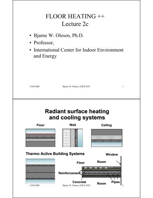
Radiant surface heating<br />
and cooling systems<br />
Floor Wall<br />
Thermo Active Building Systems<br />
Floor<br />
Reinforcement<br />
Ceiling<br />
Room<br />
Window<br />
Concrete Room<br />
Pipes<br />
Room<br />
Pipes<br />
15/02/2009 Bjarne W. Olesen, ICIEE-DTU 2
Determination of Heating and<br />
Cooling Capacity<br />
15/02/2009 Bjarne W. Olesen, ICIEE-DTU 3<br />
STANDARDS<br />
• prEN 1264-2, 2007: Prove methods for the determination of the thermal<br />
output of floor eating systems using calculation and<br />
test methods<br />
– EN 1264-1, 1999: Floor heating: Systems and components - Part 1 :<br />
Definitions and symbols<br />
– EN 1264-3, 1999: Floor heating: Systems and components - Part 3 :<br />
Dimensioning<br />
– EN 1264-4, 2001: Floor heating: Systems and components - Part 4:<br />
Installation<br />
• prEN 1264-5, 2007: Heating and cooling surfaces embedded in floors,<br />
ceilings and walls — Determination of thermal output and<br />
cooling output<br />
• EN15377-1, 2007: Embedded water based surface heating and cooling<br />
systems: Determination of the design heating and<br />
cooling capacity<br />
• EN15377-2, 2007: Embedded water based surface heating and cooling<br />
systems: Design, Dimensioning and Installation<br />
• EN15377-3, 2007: Embedded water based surface heating and cooling<br />
systems: Optimizing for use of renewable energy sources<br />
15/02/2009 Bjarne W. Olesen, ICIEE-DTU 4
SURFACE <strong>HEATING</strong> AND<br />
COOLING<br />
Heat transfer coefficient<br />
Heating<br />
Cooling<br />
11,0<br />
7,0<br />
Floor<br />
6,0<br />
11,0<br />
15/02/2009 Bjarne W. Olesen, ICIEE-DTU 5<br />
8,0<br />
Ceiling<br />
Floor heating and Ceiling cooling: q = 8,92 (θ S,m - θ i ) 1,1<br />
Wall heating and Wall cooling: q = 8 ( θ S,m - θ i )<br />
Ceiling heating: q = 6 ( θ S,m - θ i )<br />
Floor cooling q = 7 ( θ S,m - θ i )<br />
Where<br />
q is the heat flux in W/m2<br />
θS,m is average surface temperature<br />
is room design temperature (operative)<br />
θ i<br />
8,0<br />
11,5<br />
10,5<br />
9,5<br />
8,5<br />
7,5<br />
6,5<br />
5,5<br />
Wall<br />
SURFACE <strong>HEATING</strong> AND<br />
COOLING<br />
Heat transfer coefficient<br />
15/02/2009 Bjarne W. Olesen, ICIEE-DTU 6<br />
W/m 2 K
SURFACE <strong>HEATING</strong> AND<br />
COOLING<br />
Max. - Min. Surface temperature<br />
Heating Cooling<br />
29<br />
20<br />
Floor<br />
35<br />
20<br />
15/02/2009 Bjarne W. Olesen, ICIEE-DTU 7<br />
27<br />
17<br />
Perimeter<br />
40<br />
17<br />
Ceiling<br />
45<br />
40<br />
35<br />
30<br />
25<br />
20<br />
15<br />
Wall<br />
MAXIMUM <strong>HEATING</strong> AND<br />
COOLING CAPACITY<br />
Heating<br />
Cooling<br />
99<br />
42<br />
Floor<br />
165<br />
42<br />
15/02/2009 Bjarne W. Olesen, ICIEE-DTU 8<br />
42<br />
99<br />
Perimeter<br />
160<br />
72<br />
Ceiling<br />
200<br />
180<br />
160<br />
140<br />
120<br />
100<br />
80<br />
60<br />
40<br />
20<br />
0<br />
Wall<br />
o C<br />
W/m 2
Universal single power function<br />
(EN1264)<br />
<strong>FLOOR</strong> <strong>HEATING</strong><br />
• CALCULATION OF THE HEAT OUTPUT W/m²<br />
• System factor B will depend on type of system and type of pipe<br />
System constant~ 6.5 - 6.7 Factors<br />
Temperature difference<br />
(Room - water)<br />
m<br />
B T<br />
m<br />
D<br />
T D u<br />
Ba aaat Floor covering Pipe spacing Pipe diameter Screed covering<br />
15/02/2009 Bjarne W. Olesen, ICIEE-DTU 9<br />
15/02/2009 Bjarne W. Olesen, ICIEE-DTU 10<br />
m<br />
u<br />
<strong>HEATING</strong> CAPACITY<br />
• Floor covering a B, spacing a T, and covering<br />
a D factors in tables<br />
• mT = 1- T/0.075 (T = Pipe spacing, m)<br />
• mu = 100 ( 0.045 - su )(su = covering thickness, m)<br />
• mD= 250 ( D-0.020 ) (D = Pipe diameter, m )<br />
w
Table A.1 : Floor covering factor a B depending on the thermal resistance R ,B of the floor covering<br />
and the thermal conductivityE of the screed for type A and C systems<br />
R ,B<br />
(m2K/W) 0 0,05 0,10 0,15<br />
E<br />
(W/(m.K)) a B<br />
2,0 1,196 0,833 0,640 0,519<br />
1,5 1,122 0,797 0,618 0,505<br />
1,2 1,058 0,764 0,598 0,491<br />
1,0 1,000 0,734 0,579 0,478<br />
0,8 0,924 0,692 0,553 0,460<br />
0,6 0,821 0,632 0,514 0,433<br />
NOTE : The floor covering factor a B may be determined with<br />
the following equation:<br />
a<br />
B<br />
1 su,0<br />
<br />
u,<br />
0<br />
<br />
1 su,<br />
0<br />
R<br />
<br />
E<br />
,<br />
B<br />
where = 10,8 W/m2K;u,0 = 1 W/m.K; s u,0 = 0,045 m<br />
15/02/2009 Bjarne W. Olesen, ICIEE-DTU 11<br />
15/02/2009 Bjarne W. Olesen, ICIEE-DTU 12
<strong>HEATING</strong> CAPACITY<br />
1.50<br />
1.00<br />
0.50<br />
0.00<br />
FACTOR FOR <strong>FLOOR</strong> COVERING, a B<br />
0.49<br />
0.46<br />
0.15<br />
0.1<br />
0.60<br />
0.55<br />
m 2 K/W<br />
0.76<br />
0.69<br />
0.05<br />
1.06<br />
0.92<br />
1.20<br />
0.80<br />
Screed<br />
15/02/2009 Bjarne W. Olesen, ICIEE-DTU 13<br />
COOLING CAPACITY<br />
• Total factor for the following example<br />
• 17 mm pipe<br />
• 45 mm concrete above pipes<br />
1<br />
• Concrete ~ 1,2 W/mK<br />
0,8<br />
0,6<br />
0,4<br />
0,2<br />
0<br />
300<br />
0,42<br />
0,52<br />
T, mm<br />
150<br />
0,57<br />
15/02/2009 Bjarne W. Olesen, ICIEE-DTU 14<br />
0,77<br />
0,66<br />
75<br />
0,96<br />
0<br />
0,01<br />
0,1 Rb, m 2 K/W
COOLING CAPACITY<br />
• Cooling capacity in W/m²for the following example<br />
• 17 mm PEX-pipe<br />
• 45 mm concrete above pipes 50<br />
• Concrete ~ 1,2 W/mK<br />
• Space temperature 26 °C 40<br />
•<br />
•<br />
Supply water temperature 14 °C<br />
30<br />
Return water temperature 19 W/m°C 20<br />
2<br />
10<br />
0<br />
300<br />
20<br />
25<br />
15/02/2009 Bjarne W. Olesen, ICIEE-DTU 15<br />
Heat exchange [W/m2]<br />
T mm<br />
150<br />
ALUMINUM HC device: Floor Heating & Cooling (type B), R=0.01~0.1,<br />
T=150 & 300<br />
160<br />
140<br />
120<br />
100<br />
80<br />
60<br />
40<br />
20<br />
0<br />
T=150, R=0.01<br />
T=150, R=0.1<br />
T=300, R=0.01<br />
T=300, R=0.1<br />
27<br />
37<br />
75<br />
32<br />
46<br />
0,1<br />
0,01<br />
R b m 2 K/W<br />
Heating/ cooling capacity, EN1264<br />
and EN 15377<br />
-15 -10 -5 0 5 10 15 20 25 30<br />
Heating/cooling medium differential temperature ΔθH=θH-θi [°C]<br />
Figure 4.17 Heat exchange between the surface (with ceramic tiles, wooden<br />
parquets or carpet R?B=0.1 and no covering R?B=0) and the space when aluminium<br />
heat conductive device used<br />
15/02/2009 Bjarne W. Olesen, ICIEE-DTU 16
Thermal resistance methods<br />
15/02/2009 Bjarne W. Olesen, ICIEE-DTU 17<br />
Pipes embedded in a<br />
massive concrete layer<br />
15/02/2009 Bjarne W. Olesen, ICIEE-DTU 18
Thermal resistance method<br />
<br />
v<br />
R t<br />
R 1<br />
R 2<br />
15/02/2009 Bjarne W. Olesen, ICIEE-DTU 19<br />
15/02/2009 Bjarne W. Olesen, ICIEE-DTU 20<br />
<br />
<br />
c<br />
q 1<br />
q 2<br />
s 1<br />
s 2<br />
Capillar tubes
v R t<br />
Thermal resistance<br />
methods<br />
R 1<br />
R 2<br />
15/02/2009 Bjarne W. Olesen, ICIEE-DTU 21<br />
<br />
Thermal resistance method<br />
15/02/2009 Bjarne W. Olesen, ICIEE-DTU 22<br />
<br />
<br />
<br />
c<br />
s <br />
2
Thermal resistance method<br />
15/02/2009 Bjarne W. Olesen, ICIEE-DTU 23<br />
q K Δθ<br />
i<br />
K H <br />
Thermal resistance<br />
methods<br />
H<br />
H H i<br />
H<br />
W/m<br />
²<br />
is the differential temperature of the heating/cooling<br />
medium<br />
equivalent coefficient of thermal<br />
conductivity<br />
/( RHC<br />
R ) W/m²<br />
C<br />
KH 1<br />
i<br />
Total thermal resistance between the heat source and the<br />
conducting layer<br />
m² °C/W<br />
T<br />
RHC T<br />
RR<br />
T<br />
RR<br />
, con RU<br />
R<br />
2<br />
15/02/2009 Bjarne W. Olesen, ICIEE-DTU 24<br />
R HC<br />
CL<br />
R i<br />
R e
15/02/2009 Bjarne W. Olesen, ICIEE-DTU 25<br />
Finite Element Method<br />
15/02/2009 Bjarne W. Olesen, ICIEE-DTU 26
Laboratory testing<br />
15/02/2009 Bjarne W. Olesen, ICIEE-DTU 27<br />
UNIFORMITY OF <strong>FLOOR</strong> SURFACE<br />
TEMPERATURE<br />
Maximum<br />
Mean<br />
Minimum<br />
15/02/2009 Bjarne W. Olesen, ICIEE-DTU 28
W/ 2 m<br />
RADIANT <strong>FLOOR</strong> COOLING<br />
15/02/2009 Bjarne W. Olesen, ICIEE-DTU 29<br />
155<br />
135<br />
115<br />
95<br />
75<br />
55<br />
35<br />
15<br />
COOLING CAPACITY<br />
CALCULATED CAPACITY IN AN ATRIUM<br />
WITH DIRECT SUNSHINE ON THE <strong>FLOOR</strong><br />
107<br />
15/02/2009 Bjarne W. Olesen, ICIEE-DTU 30<br />
129<br />
148<br />
25 20 15<br />
Supply water temperature, o C
Floor surface temperature<br />
Heating/ cooling capacity, EN1264 and EN 15377<br />
Heat exchange [W/m2]<br />
ALUMINUM HC device: Floor Heating & Cooling (type B), R=0.01~0.1,<br />
T=150 & 300<br />
160<br />
140<br />
120<br />
100<br />
80<br />
60<br />
40<br />
20<br />
0<br />
T=150, R=0.01<br />
T=150, R=0.1<br />
T=300, R=0.01<br />
T=300, R=0.1<br />
-15 -10 -5 0 5 10 15 20 25 30<br />
Heating/cooling medium differential temperature ΔθH=θH-θi [°C]<br />
Figure 4.17 Heat exchange between the surface (with ceramic tiles, wooden<br />
parquets or carpet R?B=0.1 and no covering R?B=0) and the space when aluminium<br />
heat conductive device used<br />
15/02/2009 Bjarne W. Olesen, ICIEE-DTU 31<br />
Floor covering<br />
Heat supply<br />
Pipe distance<br />
T water-average –t room<br />
Diagram for<br />
17x2 mm pipe<br />
45 mm screed<br />
= 1,2 W/mK<br />
15/02/2009 Bjarne W. Olesen, ICIEE-DTU 32
Water flow rate<br />
Pressure drop<br />
Water<br />
15/02/2009 Bjarne W. Olesen, ICIEE-DTU 33<br />
The design supply water<br />
temperature is determined<br />
according to the room with the<br />
highest heat load or with the highest<br />
heat resistance of the floor covering.<br />
15/02/2009 Bjarne W. Olesen, ICIEE-DTU 34
Calculation of the water supply temperature<br />
Heat resistance of the floor covering R ,B = 0,15 m 2 K/W<br />
Pipe spacing 15 cm<br />
Design heat loss 80 W/m 2<br />
From the dimensioning diagram<br />
Difference between average water temperature and room:<br />
H = 28,9 K<br />
Average water temperature:<br />
HM= 20°C + 28,9 K = 48,9 °C<br />
Temperature difference (supply-return) for the critical room: EN1264 = 5 K<br />
Design supply water temperature:<br />
Vdim = HM + /2 = 48,9°C +2,5 K = 51,4 °C<br />
15/02/2009 Bjarne W. Olesen, ICIEE-DTU 35<br />
80 W/m 2<br />
FB= 27,3 °C<br />
0,15m 2 K/W<br />
Diagram for<br />
dimensioning<br />
H<br />
HM<br />
= 28,9°C<br />
= 48,9 °C<br />
Vausl = 51,4 °C<br />
Boundary<br />
conditions<br />
S å = 45 mm<br />
å = 1,2 W/mK<br />
15/02/2009 Bjarne W. Olesen, ICIEE-DTU 36
DIMENSIONING AND<br />
DESIGN<br />
• Pipe diameter<br />
• Pipe spacing<br />
• Pipe layout<br />
• Water flow rate<br />
• Pipe circuits<br />
15/02/2009 Bjarne W. Olesen, ICIEE-DTU 37<br />
Kombizone<br />
15/02/2009 Bjarne W. Olesen, ICIEE-DTU 38<br />
RL<br />
VL
Perimeter and occupied space<br />
15/02/2009 Bjarne W. Olesen, ICIEE-DTU 39<br />
Occupied space<br />
15/02/2009 Bjarne W. Olesen, ICIEE-DTU 40<br />
RL<br />
VL<br />
RL<br />
VL<br />
RL<br />
VL
VL<br />
RL<br />
Cover as much surface as possible<br />
Possible solution<br />
15/02/2009 Bjarne W. Olesen, ICIEE-DTU 41<br />
15/02/2009 Bjarne W. Olesen, ICIEE-DTU 42
15/02/2009 Bjarne W. Olesen, ICIEE-DTU 43<br />
Joints in the concrete<br />
15/02/2009 Bjarne W. Olesen, ICIEE-DTU 44<br />
R<br />
L<br />
V<br />
L
Example<br />
15/02/2009 Bjarne W. Olesen, ICIEE-DTU 45<br />
Correction for covered<br />
surface<br />
Floor area<br />
Korrektur af<br />
Normvarmetabet<br />
Største varmestrøm<br />
Bad tages ikke med<br />
15/02/2009 Bjarne W. Olesen, ICIEE-DTU 46
Tilslutningsledninger<br />
Varmeafgivel se [W/m]<br />
egen varmekreds<br />
gennemgående<br />
Total rørlængde<br />
15/02/2009 Bjarne W. Olesen, ICIEE-DTU 47<br />
15<br />
14<br />
13<br />
12<br />
11<br />
10<br />
9<br />
Forbindelses rör<br />
45 46 47 48 49 50 51 52 53 54 55 56 57 58<br />
Dimensionerende fremlöbstemperatur [°C]<br />
45 mm Beton, Ü = 1,2 W/mK<br />
15/02/2009 Bjarne W. Olesen, ICIEE-DTU 48
q<br />
r<br />
Vandstrøm:<br />
Water flow<br />
<br />
0,<br />
86<br />
c <br />
TFTR TF<br />
TR<br />
qr: Water Vandstrøm flow l/h<br />
15/02/2009 Bjarne W. Olesen, ICIEE-DTU 49<br />
<br />
<br />
c: Vands varmefylde Wh/kgC<br />
Specific heat capacity<br />
Φ: Heat Varmeydelse supply W<br />
Tryktabsdiagramdiagram<br />
for 17 x 2 mm rør<br />
15/02/2009 Bjarne W. Olesen, ICIEE-DTU 50
14<br />
Water flow rate<br />
Pressure drop 14 x 2 mm<br />
pipe<br />
Pressure drop<br />
Water<br />
15/02/2009 Bjarne W. Olesen, ICIEE-DTU 51<br />
5 1 / 4<br />
Valve<br />
position<br />
15/02/2009 Bjarne W. Olesen, ICIEE-DTU 52
Valve position<br />
15/02/2009 Bjarne W. Olesen, ICIEE-DTU 53<br />
INSTALLATION<br />
• Floor systems<br />
• Wall systems<br />
•Ceilingsystems<br />
• TABS Thermo Active Building Systems<br />
• Pre-fabrication<br />
15/02/2009 Bjarne W. Olesen, ICIEE-DTU 54
1. Screed-concrete 2. Pipe<br />
3. Plastic foil<br />
4. Insulation 5. Acoustic insulation<br />
6. PE foil<br />
7. covering 8. Concrete slab<br />
15/02/2009 Bjarne W. Olesen, ICIEE-DTU 55<br />
15/02/2009 Bjarne W. Olesen, ICIEE-DTU 56
15/02/2009 Bjarne W. Olesen, ICIEE-DTU 57<br />
15/02/2009 Bjarne W. Olesen, ICIEE-DTU 58
Radiant surface heating<br />
and cooling systems<br />
Floor Wall<br />
Thermo Active Building Systems<br />
Floor<br />
Reinforcement<br />
Ceiling<br />
Room<br />
Window<br />
Concrete Room<br />
Pipes<br />
Room<br />
Pipes<br />
15/02/2009 Bjarne W. Olesen, ICIEE-DTU 59<br />
15/02/2009 Bjarne W. Olesen, ICIEE-DTU 60
Calculation methods<br />
1. Rough sizing method based on a standard<br />
calculation of the cooling load (accuracy 20-30%).<br />
To be used based on the knowledge of the peak<br />
value for heat gains (section 5.1)<br />
2. Simplified method using diagrams for sizing<br />
based on 24 hours values of heat gains (accuracy<br />
15-20%, section 5.2).<br />
3. Simplified model based on finite difference<br />
method (accuracy 10-15%). Detailed dynamic<br />
15/02/2009 Bjarne W. Olesen, ICIEE-DTU 61<br />
15/02/2009 Bjarne W. Olesen, ICIEE-DTU 62
15/02/2009 Bjarne W. Olesen, ICIEE-DTU 63


