Renewable Energy Technology Assessments - Kauai Island Utility ...
Renewable Energy Technology Assessments - Kauai Island Utility ...
Renewable Energy Technology Assessments - Kauai Island Utility ...

You also want an ePaper? Increase the reach of your titles
YUMPU automatically turns print PDFs into web optimized ePapers that Google loves.
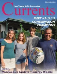
Kaua’i <strong>Island</strong> <strong>Utility</strong> Cooperative<br />
<strong>Renewable</strong> <strong>Energy</strong> <strong>Technology</strong> <strong>Assessments</strong> Table of Contents<br />
Figure 1-3. Change in <strong>Technology</strong> Screening Scores by Timeframe............................. 1-6<br />
Figure 1-4. Selected Project Locations. .......................................................................... 1-7<br />
Figure 1-5. Levelized Cost Premium Supply Curve..................................................... 1-16<br />
Figure 1-6. Scoring Results Breakdown. ...................................................................... 1-18<br />
Figure 1-7. Break-Even Cost Analysis for <strong>Renewable</strong> vs. KIUC’s Short Term Avoided<br />
Costs. ............................................................................................................ 1-22<br />
Figure 2-1. US Net <strong>Renewable</strong> Electricity Generation, GWh (1000’s). (EIA 2002) ..... 2-6<br />
Figure 2-2. US Net <strong>Renewable</strong> Electrical Capacity, GW. (EIA 2002)........................... 2-7<br />
Figure 2-3. Historic Electricity Generation in <strong>Kauai</strong> (Data: KIUC)............................... 2-8<br />
Figure 3-1. Biomass Sources, Processes, Products, and Markets................................... 3-3<br />
Figure 3-2. 35 MW Biomass Combustion Plant............................................................. 3-4<br />
Figure 3-3. Alholmens Kraft Multi-Fuel CFB (Source: Kvaerner). ............................. 3-12<br />
Figure 3-4. 500 m 3 Digester Treating Manure from a 10,000 Pig Farm in China........ 3-15<br />
Figure 3-5. LFG Well Drilling...................................................................................... 3-19<br />
Figure 3-6. Ethanol Production Facility in Wisconsin.................................................. 3-23<br />
Figure 3-7. Central Wayne Waste to <strong>Energy</strong> Plant........................................................ 3-33<br />
Figure 3-8. Plasma Arc Torch Operating...................................................................... 3-39<br />
Figure 3-9. 3 MW Small Hydro Plant........................................................................... 3-43<br />
Figure 3-10. CC-OTEC Using the Kalina Cycle (Source: Saga University)................ 3-48<br />
Figure 3-11. Onshore Wave <strong>Energy</strong> Devices (Source: EU’s Atlas Project)................. 3-51<br />
Figure 3-12. AquaBuOY, Archimedes Wave Swing, PowerBuoy, and Pelamis devices.<br />
(Sources: Aqua<strong>Energy</strong> Group Ltd., AWS BV, Ocean Power Technologies, and<br />
Ocean Power Delivery). ............................................................................... 3-53<br />
Figure 3-13. Photovoltaic Solar Panel Installation. ...................................................... 3-58<br />
Figure 3-14. <strong>Kauai</strong> Solar Insolation (Source: Hawaii Statewide GIS Program). ......... 3-61<br />
Figure 3-15. Parabolic Trough Field (Source: Union of Concerned Scientists)........... 3-63<br />
Figure 3-16. Solar Two Central Receiver Installation.................................................. 3-63<br />
Figure 3-17. Parabolic Dish Receiver (Source: Stirling <strong>Energy</strong> Systems). .................. 3-64<br />
Figure 3-18. 9 MW Kahuku Wind Farm on Oahu, Now Decommissioned ................. 3-68<br />
Figure 3-19. <strong>Kauai</strong> Wind <strong>Energy</strong> Resources, Class 3 and Above. ...................................73<br />
Figure 3-20. Geothermal District Heating Equipment.................................................. 3-74<br />
Figure 3-21. Engine Generator (Source: Caterpillar Corporation). .............................. 3-77<br />
Figure 3-22. Combustion Turbine Section (Source: Langston)................................... 3-79<br />
Figure 3-23. Microturbine Cutaway View (Source: Capstone Turbine Corporation.). 3-82<br />
Figure 3-24. 200 kW Fuel Cell (Source: UTC Fuel Cells)........................................... 3-84<br />
Figure 4-1. Trends in Average Levelized Cost of <strong>Energy</strong> for <strong>Renewable</strong> Resources. ... 4-8<br />
Figure 4-2. Range of Levelized Cost for <strong>Renewable</strong> Technologies. .............................. 4-9<br />
21 March 2005 TC-10 Black & Veatch