Batch Gravitational Sedimentation of Slurries
Batch Gravitational Sedimentation of Slurries
Batch Gravitational Sedimentation of Slurries

Create successful ePaper yourself
Turn your PDF publications into a flip-book with our unique Google optimized e-Paper software.
Journal <strong>of</strong> Colloid and Interface Science 245, 178–186 (2002)<br />
doi:10.1006/jcis.2001.7938, available online at http://www.idealibrary.com on<br />
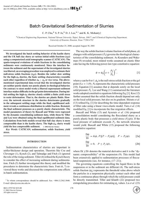
<strong>Batch</strong> <strong>Gravitational</strong> <strong>Sedimentation</strong> <strong>of</strong> <strong>Slurries</strong><br />
C. P. Chu, ∗ S. P. Ju, ∗ D. J. Lee, ∗,1 and K. K. Mohanty†<br />
∗ Chemical Engineering Department, National Taiwan University, Taipei, Taiwan, 10617; and †Chemical Engineering Department,<br />
University <strong>of</strong> Houston, Houston, Texas 77204-4792<br />
We investigated the batch settling behavior <strong>of</strong> the kaolin slurry<br />
and the UK ball clay slurry at various initial solids fractions (φ0s)<br />
using a computerized axial tomography scanner (CATSCAN). The<br />
spatio-temporal evolutions <strong>of</strong> solids fractions in the consolidating<br />
sediments were continuously monitored. Since the interface between<br />
the sediment and the supernatant <strong>of</strong> the investigated slurries<br />
was blurred, an averaging procedure was employed to estimate their<br />
null-stress solids fractions (φgs). Besides the rather slow settling<br />
for the high-φ0 slurries, the basic settling characteristics resemble<br />
each other regardless <strong>of</strong> whether φ0 >φgor vice versa. The abovementioned<br />
experimental data reveal that the investigated slurries<br />
are neither purely elastic nor purely plastic in rheological behavior.<br />
On contrary to most model works a blurred supernatant-sediment<br />
interface makes difficulty in the gel point determination. During initial<br />
settling the high-φ0 slurries clearly exhibit a finite yield stress<br />
to resist deformation. That is, the slurries are plastic fluids. However,<br />
the network structure in the slurries deteriorates gradually<br />
in the subsequent settling stage while the final, equilibrated sediment<br />
reveals a continuous distribution in solids fraction. Restated,<br />
the final sediment possesses as a purely elastic characteristic. The<br />
model parameters <strong>of</strong> theory by Buscall and White were regressed<br />
by the dynamic consolidating sediment data, while those by Tiller<br />
and Leu were obtained using the final equilibrated sediment data.<br />
Calculations from both models reveal that ball clay slurry is more<br />
compressible than is the kaolin slurry. The high-φS0 slurry would<br />
yield the less compressible sediment. C○ 2002 Elsevier Science<br />
Key Words: CATSCAN; sedimentation; solids fractions; yield<br />
stress.<br />
INTRODUCTION<br />
<strong>Sedimentation</strong> characteristics <strong>of</strong> slurries are important in<br />
settler/thickener design and operation. Theorists like Coe and<br />
Clevenger (1), Kynch (2), and Talmadge and Fitch (3) ignored<br />
the role <strong>of</strong> the rising sediment. Tiller (4) refined the Kynch theory<br />
to consider the effect <strong>of</strong> increasing sediment during sedimentation.<br />
Fitch (5) further investigated this theory and modified the<br />
procedures to determine the characteristic lines. Font (6, 7) reviewed<br />
these works and discussed the compression zone effects<br />
in batch sedimentation.<br />
1 To whom correspondence should be addressed. Fax: +886-2-2362-3040.<br />
E-mail: djlee@ccms.ntu.edu.tw.<br />
0021-9797/02 $35.00<br />
C○ 2002 Elsevier Science<br />
All rights reserved.<br />
Received October 25, 2000; accepted August 30, 2001<br />
178<br />
The way the solids fraction (volume fraction <strong>of</strong> solid phase, φ)<br />
changes with solid pressure (PS) governs the rheological characteristics<br />
<strong>of</strong> the consolidating sediment. As Koenders and Wakeman<br />
(9) revealed, most related works assumed an elastic filter<br />
cake having the following power-law type constitutive equation:<br />
φ = φg<br />
<br />
a + PS<br />
β , [1]<br />
P0<br />
where a canbe0or1.φgis the null-stress solids fraction or the gel<br />
point if a = 1 (9). P0 represents the characteristic solid pressure<br />
(10). Equation [1] assumes that φ depends sorely on the local<br />
solid pressure PS. Lee and Wang (11) summarized the literature<br />
works adopted constitutive equations following Eq. [1]. Kos (12)<br />
further assumed that the solids fraction should depend not only<br />
on the local solid pressure, but also on its gradient. Shirato et al.<br />
(13) refined Eq. [1] for describing the time-dependent response<br />
<strong>of</strong> filter cake using a linear visco-elastic model. Tien et al. (14)<br />
modified Eq. [1] to incorporate the fine migration effects.<br />
Buscall and White (15) and Ayzerais et al. (16) proposed<br />
a consolidation model considering the flocculated slurry as a<br />
purely plastic body that possesses a yield stress (Py(φ)). If the<br />
local pressure <strong>of</strong> sediment exceeds Py, the network structure<br />
would yield. Buscall and White (15) proposed the following<br />
constitutive equation:<br />
Dφ<br />
Dt = k(φ, P)[P − Py(φ)], P > Py(φ) [2a]<br />
Dφ<br />
Dt = 0, P ≤ Py (φ) , [2b]<br />
where D( )/Dt denotes the material derivative and k is the “dynamic<br />
compressibility” <strong>of</strong> the suspension (9). This model had<br />
been extensively applied to sedimentation processes <strong>of</strong> flocculated<br />
suspensions (see, for instance, (17–21)).<br />
The governing equations controlling the liquid flows in the<br />
suspension or in the sediment are different (4). The null-stress<br />
solids fraction (φg) represents the threshold value above which<br />
the particles in a suspension physically contact each other and<br />
form a continuous phase through which the solid pressure could<br />
be directly transmitted. Tiller and Khatib (22) proposed two<br />
extrapolating procedures for estimating φg values. Lu et al. (23)
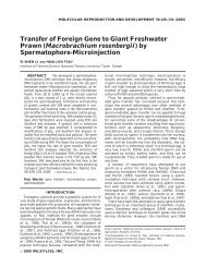
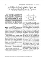
FIG. 1. Schematics <strong>of</strong> slurry settling. (a) Purely elastic sediment; (b) purely<br />
plastic sediment.<br />
adopted low-head filtration test to determine the surface cake<br />
porosity and examine the effects <strong>of</strong> slurry concentration and<br />
operating conditions. Determination <strong>of</strong> φ0 for certain slurries<br />
is extremely difficult since the interface between the sediment<br />
and the suspension could be blurred. The sudden jump in<br />
solids fraction when moving from settling slurry to sediment as<br />
suggested by the idealized theory may not be easily observed<br />
(as discussed later).<br />
Researchers adopted nondestructive techniques to obtain the<br />
relevant variable in the solid/liquid separation processes as a<br />
function <strong>of</strong> space and time, such as the use <strong>of</strong> γ -ray (18, 24),<br />
NMR (25–27), and X-ray (17, 28–33). Buscall (34) reviewed<br />
the pertinent literature before 1990. Shen et al. (19) adopted the<br />
yield-stress model by Buscall and White (15) for interpreting<br />
their settling data, and noted that the model was valid during the<br />
initial phase <strong>of</strong> settling/filtration <strong>of</strong> the “pliant” systems (with<br />
initial solid weight exceeds the corresponding yield stress). For<br />
the “stiff” systems (with initial solid weight being lower than<br />
the yield stress), on the other hand, no consolidation occurred<br />
in the initial stage <strong>of</strong> experiments.<br />
We consider the cases at φ0 >φgwith all particles in the initial<br />
suspension physically contact with each other and form a network<br />
matrix. Figure 1a represents the one-dimensional sedimentation<br />
process with the purely elastic sediment, in which z = 0<br />
denotes the bottom and z = h0 represents the slurry surface.<br />
Since the transmission <strong>of</strong> solid pressure through the network the<br />
sediment would continuously yield at the beginning <strong>of</strong> the test.<br />
Restated, no portion <strong>of</strong> the sediment could be kept at φ0 while no<br />
SEDIMENTATION OF SLURRIES 179<br />
constant-φ0 regime could be noticeable in the sediment. Moreover,<br />
the solids fraction in the final sediment should be <strong>of</strong> a continuously<br />
varying manner with no apparent constant-φ0 regime<br />
(like Fig. 1a). For a purely plastic sediment with a finite yield<br />
stress, on the other hand, even at φ0 >φg the sediment would<br />
not deform if the local solid pressure has not exceeded Py(φ0).<br />
Therefore, a constant-φ0 regime could persist during settling<br />
(Fig. 1b). The final, equilibrated sediment would also possess<br />
the constant-φ0 regime (like Fig. 1b). The batch sedimentation<br />
tests <strong>of</strong> high-φ0 slurries could therefore provide the information<br />
on the validity <strong>of</strong> the above-mentioned model frameworks.<br />
This work employed the computerized axial tomography<br />
scanner (CATSCAN) for investigating the batch-settling behavior<br />
<strong>of</strong> kaolin slurry and UK ball clay slurry, particularly on the<br />
effects <strong>of</strong> φ0. We first demonstrated that, since the two investigated<br />
slurries exhibit a blurred supernatant–sediment interface<br />
due to marked back-diffusion effect, the determination <strong>of</strong> their<br />
φg values were made through an averaging procedure. Then, we<br />
revealed the feasibility <strong>of</strong> using the purely elastic or the purely<br />
plastic constitutive models to interpret the obtained sedimentation<br />
data.<br />
EXPERIMENTAL<br />
Samples<br />
Kaolin slurries and UK ball clay slurries were prepared by<br />
mixing fixed amount <strong>of</strong> powders with 0.1 M NaClO4 solution<br />
in distilled water to provide a high ionic strength to prevent the<br />
interference <strong>of</strong> other ions that might be released from the particle<br />
surfaces. The pH values were fixed at 7.0. The particle<br />
size distribution <strong>of</strong> slurry was determined by a Sedigraph<br />
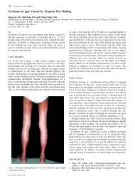
FIG. 2. The relationship between CT number and solids fraction in kaolin<br />
and clay slurries.
180 CHU ET AL.<br />
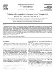
FIG. 3. The time evolutions <strong>of</strong> solids fraction for kaolin slurries. (a) φ0 = 0.01; (b) φ0 = 0.05; (c) φ0 = 0.08; (d) φ0 = 0.12; (e) φ0 = 0.15.<br />
5100 C (Micromeritics), giving a mean diameter <strong>of</strong> 6.3 µm<br />
for kaolin slurry and 2.5 µm for clay slurry. An Accupyc Pycometer<br />
1330 (Micromeritics) measured the true solid density.<br />
The results are 2730 kg/m3 for kaolin powders and<br />
2580 kg/m3 for ball clay powders. The Zetasizer 2000 (MAR-<br />
LVERN) measured the ζ -potentials <strong>of</strong> suspension. The results<br />
are −17.7 mV for kaolin slurry and −22.1 mV for clay slurry.<br />
CATSCAN<br />
<strong>Batch</strong> settling experiments were conducted in a settling cylinder<br />
that had a height <strong>of</strong> 20 cm and a diameter <strong>of</strong> 9.5 cm, and<br />
were continuously monitored with the CATSCAN (DeltaScan<br />
2060; 100 kV, 75 mA). The X-ray attenuations, which are normally<br />
presented as dimensionless scale, the CT number (35),<br />
could be obtained from a horizontal section. Bergstrom (18)<br />
adopted similar procedures using their γ -ray apparatus. Preliminary<br />
tests revealed that the CT number for the 0.1 M NaClO4<br />
solution is essentially zero since the dissolved salts do not absorb<br />
a significant amount <strong>of</strong> X-ray. Furthermore, the correlations between<br />
CT number and the solids fraction are noted for the kaolin<br />
and clay slurries, as demonstrated in Fig. 2. The uncertainties in<br />
axial position measurement and the local solid volume fraction
FIG. 3—Continued<br />
were 2.5 mm and 0.1%, respectively, which are close to those<br />
reported in Auzerais et al. (17).<br />
TIME EVOLUTIONS<br />
Figures 3 and 4 depict the spatio-temporal evolutions <strong>of</strong> crosssectional<br />
average solids fraction measured for kaolin and clay<br />
slurries during the first 6000 s and those at equilibrium. The<br />
mean solids fraction is interpreted as follows:<br />
φmea =<br />
h0<br />
0<br />
φ dz<br />
, [3]<br />
where h0 is 20 cm, the height <strong>of</strong> the slurry. The calculated φmea<br />
data all range from 0.98 to 1.03φ0, which partially support the<br />
accuracy <strong>of</strong> the solids fraction distributions presented in Figs. 3<br />
and 4.<br />
For both slurries, the settling rates decrease substantially with<br />
increasing φ0, while the effects are more significant for the<br />
clay slurries than for the kaolin slurries. For all slurries initially<br />
at φ0, a sediment layer appears at the tube bottom during<br />
settling, while a constant-concentration regime at φ0 retains<br />
above this layer regardless <strong>of</strong> the range <strong>of</strong> φ0. The basic characteristics<br />
<strong>of</strong> settling are similar for slurries at φ0 >φgto those<br />
at φ0 0.08, the particles in the present slurries<br />
would physically contact each other and the whole slurry<br />
should be regarded as the sediment body at the start <strong>of</strong> the<br />
test.<br />
The experimental range (0.01–0.15) has covered both the<br />
φ0 φg cases. Hence, the existence <strong>of</strong> the<br />
constant-φ0 regime in Figs. 3 and 4 represents the yield stress<br />
l0
182 CHU ET AL.<br />
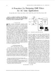
FIG. 4. The time evolutions <strong>of</strong> solids fraction for clay slurries. (a) φ0 = 0.02; (b) φ0 = 0.05; (c) φ0 = 0.08; (d) φ0 = 0.12; (e) φ0 = 0.15.<br />
<strong>of</strong> the settling sediment, thereby supporting the purely plastic<br />
model by Buscall and White (15). As settling proceeds, the<br />
constant-φ0 regime in Figs. 3 and 4 gradually shrinks, accompanied<br />
by the expansion <strong>of</strong> the supernatant and sediment zones.<br />
Equilibrium could be reached at settling time ranging from 48 h<br />
to 1 week, depending on the slurry species and the φ0. Itisnoticeable<br />
that the final sediment exhibits no constant-φ0 regime.<br />
This observation, on the other hand, favors the purely elastic<br />
model by Tiller and Leu (10). Shen et al. (19) also questioned<br />
the existence <strong>of</strong> the yield stress. Apparently neither the<br />
purely elastic nor the purely plastic constitutive equations could<br />
satisfactorily interpret the whole range <strong>of</strong> sedimentation process.<br />
At the start <strong>of</strong> the high-φ0 tests a network <strong>of</strong> finite yield<br />
stress apparently exists. However, this structure seems degraded<br />
continuously at the bottom <strong>of</strong> the constant-φ0 regime, evidenced<br />
by the increasing Lc values in Figs. 3 and 4.<br />
FINAL SEDIMENT<br />
As Fig. 3 demonstrates, the equilibrated solids fractions for<br />
kaolin slurries at bottom are all around 0.2 regardless <strong>of</strong> their φ0<br />
values, indicating that the kaolin slurry is not very compressible
FIG. 4—Continued<br />
to the applied compressive pressure. On the other hand, clay<br />
slurries could be compacted more readily to form the sediment<br />
<strong>of</strong> higher solids fraction when φ0 increases (for instance, as<br />
depicted in Figs. 4a– 4e, at 6000 s φ = 0.28 and 0.34 for φ0 =<br />
0.02 and 0.15, respectively). Restated, the clay sediment is more<br />
compressible than is the kaolin sediment.<br />
Quantitative evaluation <strong>of</strong> sediment compressibility requires<br />
the local solid pressure data for the slurries. At equilibrium, the<br />
solid pressure gradient could be stated as follows:<br />
∂ PS<br />
=−ρgφ, [5]<br />
∂t<br />
where ρ is the density difference between the solid and liquid.<br />
Hence, the local solid pressure at height z is expressed as follows:<br />
PS = ρg<br />
0<br />
The solid pressure at bottom (PS|z=0) could be estimated<br />
based on the solids fraction data in Fig. 5 and Eq. [6] with<br />
z = 0. Figures 6a and 6b also represent the estimated PS|z=0<br />
data as functions <strong>of</strong> φ0. All PS|z=0 data at equilibrium are proportional<br />
to φ0, or are equal to the buoyant weight <strong>of</strong> the solid<br />
particles. This also confirms the accuracy <strong>of</strong> the present experimental<br />
measurement.<br />
Local solid pressure data could be evaluated based on Eq. [6].<br />
Figures 7a and 7b illustrate the φ versus PS curves in the final<br />
sediment. Despite certain data scattering, the local solids fraction<br />
decreases continuously with increasing φ0 at some fixed<br />
effective pressure. Comparisons between clay and kaolin slurries<br />
reveal that the former exhibits a more compressible structure<br />
than is the latter.<br />
z<br />
SEDIMENTATION OF SLURRIES 183<br />
φ dz. [6]<br />
The local structure in the sediment would be degraded owing<br />
to gravity consolidation to a level counterbalancing the corresponding<br />
yield stress. Therefore, the φ − PS curves in Fig. 7<br />
represent the φ – Py(φ) correlations. As Fig. 7 reveals, the sediment<br />
yields more readily at the low solids fraction regime than<br />
the high regime. The sediment was consolidated from the gel<br />
point to around 12–15% at a pressure less than 1–2 Pa. At a<br />
higher pressure, the sediment yields more slowly with the applied<br />
pressure. For instance, for kaolin slurry at φ0 = 15% the<br />
solids fraction increases from 15 to 20% over a pressure up to<br />
FIG. 5. The solids fraction distributions in equilibrated sediments.<br />
(a) Kaolin slurry, and (b) clay slurry. Black circles denote the corresponding<br />
null-stress solid fractions.
184 CHU ET AL.<br />
400 Pa. In fact, the structure <strong>of</strong> the final sediment at high φ0<br />
would depend only weakly on the applied pressure.<br />
Empirical equations could correlate the φ − PS curves in<br />
Fig. 7. Here we employ Eq. [1] in sample calculations since<br />
the fitting could be achieved using graphical method proposed<br />
by (10). The obtained parameters according to the graphical<br />
method were adopted as the initial guess to nonlinear regression<br />
<strong>of</strong> Eq. [1] with the experimental data. Table 1 lists the obtained<br />
results. The parameter P0 is rather low, generally around or less<br />
than 1 Pa, indicating that these slurries would largely deform at<br />
the low-pressure regime. Also, the β values are lesser for clay<br />
slurries than those for the kaolin slurries, stating that the former<br />
is more compressible than the latter. Finally, the higher φ0 would<br />
yield the lower P0 and β. Restated, the slurry with a high initial<br />
FIG. 6. The null-stress solids fraction φg, average solids fraction φav in<br />
sediment, and solid pressure at bottom PS|z=0 at different φ0; (a) kaolin slurry<br />
and (b) clay slurry.<br />
FIG. 7. The solids fraction distributions in sediment versus solid pressure<br />
at different φ0: (a) kaolin slurry, and (b) clay slurry.<br />
solid concentration would deform quickly at the low solid pressure,<br />
but would resist more readily the external applied pressure<br />
at a greater solid pressure. Therefore, in the practical regime the<br />
high-φ0 systems would pack more readily when initially form,<br />
but become rather “stiff” owing to the associated large yield<br />
stress.<br />
CONSOLIDATING SEDIMENT<br />
For demonstrating the sediment compaction effects, only the<br />
portion <strong>of</strong> sediment with φ>φgwould be herein considered.
TABLE 1<br />
Model Parameters Obtained in This Work<br />
φ0 φg U0K (φ0) (m/s) Pv (Pa) P0 (Pa) β<br />
0.01 0.089<br />
Kaolin slurries<br />
NA NA 1.60 0.30<br />
0.05 0.094 NA NA 0.80 0.15<br />
0.08 0.067 8.49 × 10⁻⁵ 207 0.50 0.18<br />
0.12 0.070 6.77 × 10⁻⁵ 377 0.50 0.15<br />
0.15 0.100 6.13 × 10⁻⁵ 448 0.90 0.10<br />
UK ball clay slurries<br />
0.02 0.079 NA NA 1.20 0.35<br />
0.05 0.094 NA NA 1.05 0.25<br />
0.08 0.083 1.36 × 10⁻⁴ 96 0.40 0.20<br />
0.12 0.077 1.11 × 10⁻⁴ 324 0.65 0.23<br />
0.15 0.082 1.01 × 10⁻⁴ 432 0.37 0.70<br />
The solid velocity <strong>of</strong> sediment at φ0 by Landman and Russel<br />
(38) is stated as follows:<br />
uS(φ0) =− dy<br />
dt =−U0K(φ0)<br />
<br />
1− ∂PS/∂z<br />
<br />
ρgφ0<br />
<br />
<br />
Py(φ0)<br />
=−U0K(φ0) 1−<br />
, [7]<br />
ρgφ0 (y − L c)<br />
where U0 is the terminal velocity <strong>of</strong> individual particle; K is the<br />
hindered factor; ρ, the density difference between the solids<br />
and the liquid; g, the gravitational acceleration; y, the upper<br />
interfacial height where φ = φ0; and Lc, the height where φ<br />
deviates from φ0 (19). Equation [5] is valid for the consolidating<br />
sediment with φ>φ0. A regime <strong>of</strong> constant φ0 is assumed to<br />
FIG. 8. Plot <strong>of</strong> dy/dt vs 1/(y − Lc) <strong>of</strong> the slurries with φ0 higher than φg.<br />
SEDIMENTATION OF SLURRIES 185<br />
exist in the consolidating sediment over the range <strong>of</strong> z = y,<br />
where PS = 0toz=Lc, where PS = Py(φ0). Hence, the plot<br />
with dy/dt versus 1/(y − Lc) estimates the U0K and Py at φ =<br />
φ0 with linear regression analysis.<br />
The investigated slurries possess a blurred suspension, while<br />
the solid pressure accumulated at yg, where φ = φg. Therefore,<br />
Eq. [5] needs correction as follows:<br />
dy<br />
dt = U0K<br />
<br />
(φ0) 1 − Py(φ0)<br />
<br />
− Pg<br />
, [8]<br />
ρgφ0(y − L c)<br />
where Pg is the accumulated solid pressure at y and could be<br />
approximated as<br />
Pg = PS|z=y ≈ ρg<br />
<br />
yg<br />
y<br />
φ dz. [9]<br />
If Eq. [8] were valid for describing the dynamics <strong>of</strong> the consolidating<br />
sediment, the curves for dy/dt versus 1/(y − Lc) data<br />
should reveal a linear character. Figure 8 shows some dy/dt versus<br />
1/(y − Lc) data sets <strong>of</strong> φ0 >φgtests. Apparently the curves<br />
in Fig. 8 reveal a linear relation during early stage <strong>of</strong> settling. For<br />
instance, for kaolin slurry at φ0 = 8%, Eq. [1] could describe<br />
the consolidation at testing time less than 1000 s. After the initial<br />
stage the settling becomes very slow (very small dy/dt)<br />
while the linear relationship breaks down. This observation corresponds<br />
to the observation by Shen et al. (1994). The yield<br />
stress <strong>of</strong> the investigated slurries could not sustain the integrity<br />
<strong>of</strong> the constant-φ0 regime which deteriorates continuously with<br />
time.<br />
Table 1 lists the best-fit Py(φ0) and U0K (φ0) for the investigated<br />
slurries in their regimes. For both slurries Py increased<br />
and U0K decreased with increasing φ0. At the same φ0 kaolin<br />
slurries have the higher Py but the lower U0K than the ball<br />
clay slurries. Therefore the kaolin slurries are “stiffer” than the<br />
clay slurries. This observation corresponds to the greater β values<br />
for the clay slurries in Table 1 when compared with the<br />
kaolin slurries. This plastic characteristic apparently degrades<br />
in the subsequent settling stage. The dy/dt versus 1/(y − Lc)<br />
data deviate from the linear regime at t > 1000 s.<br />
CONCLUSIONS<br />
This study utilized a CATSCAN to measure the spatiotemporal<br />
distributions <strong>of</strong> solids fraction for kaolin and clay slurries<br />
at various initial solid concentrations, φ0s. The CATSCAN<br />
could not directly measure the null-stress solids fraction (φg)<br />
for the investigated slurries, whose values are estimated using<br />
an averaging technique to all around 0.07–0.08, regardless <strong>of</strong><br />
the φ0.<br />
The experimental range <strong>of</strong> φ0 (0.01–0.15) has covered both<br />
the φ0 φgcases. The basic settling characteristics<br />
are similar for slurries with φ0 >φgand vice versa. A constantφ0<br />
regime is noted for both cases, beneath which a sediment
186 CHU ET AL.<br />
layer forms. There existed a finite yield stress <strong>of</strong> the settling<br />
sediment indicating that the investigated sediments are plastic<br />
fluids. However, the final sediment equilibrated with gravity exhibited<br />
no constant-φ0 regime, which indicated purely elastic<br />
sediment. The network structure in the slurries degrades gradually<br />
in the settling process.<br />
The model parameters <strong>of</strong> the theory by Buscall and White<br />
were regressed from the consolidating sediment data, while<br />
those by Tiller and Leu were obtained using the final sediment<br />
data. Both results indicate that the clay slurries are more compressible<br />
than the kaolin slurries. The higher initial solids fraction<br />
would also yield a “stiffer” sediment.<br />
ACKNOWLEDGMENTS<br />
The authors acknowledge support for this work from National Science Council,<br />
ROC. The assistance from Pr<strong>of</strong>. F. M. Tiller and Dr. Wenping Li <strong>of</strong> University<br />
<strong>of</strong> Houston to CATSCAN experiments is highly appreciated.<br />
REFERENCES<br />
1. Coe, H. S., and Clevenger, G. H., Trans. Am. Inst. Min. Eng. 55, 356 (1916).<br />
2. Kynch, G. J., Trans. Faraday Soc. 44, 166 (1952).<br />
3. Talmadge, W. P., and Fitch, E. B., Ind. Eng. Chem. 47, 38 (1955).<br />
4. Tiller, F. M., AIChE J. 27, 823 (1981).<br />
5. Fitch, B., AIChE J. 29, 940 (1983).<br />
6. Font, R., AIChE J. 34, 229 (1988).<br />
7. Font, R., Chem. Eng. Sci. 46, 2473 (1991).<br />
8. Koenders, M. A., and Wakeman, R. J., Chem. Eng. Sci. 51, 3897 (1996).<br />
9. Landman, K. A., Buscall, R., and White, L. R., AIChE J. 34, 239<br />
(1988).<br />
10. Tiller, F. M., and Leu, W. F., J. Chin. Inst. Chem. Eng. 11, 61 (1980).<br />
11. Lee, D. J., and Wang, C. H., Water Res. 34, 1 (2000).<br />
12. Kos, P., Chem. Eng. Prog. 73, 99 (1997).<br />
13. Shirato, M., Murase, T., Tokunaga, A., and Yamada, O., J. Chem. Eng. Jpn.<br />
7, 229 (1974).<br />
14. Tien, C., Bai, R., and Ramarao, B. V., AIChE J. 43, 33 (1997).<br />
15. Buscall, R., and White, L. R., J. Chem. Soc., Faraday Trans. 83, 873 (1987).<br />
16. Auzerais, F. M., Jackson, R., and Russel, W. B., J. Fluid Mech. 195, 437<br />
(1988).<br />
17. Auzerais, F. M., Jackson, R., Russel, W. B., and Murphy, W. F., J. Fluid<br />
Mech. 221, 613 (1990).<br />
18. Bergstrom, L., J. Chem Soc., Faraday Trans. 88, 3201 (1992).<br />
19. Shen, C., Russel, W. B., and Auzerais, F. M., AIChE J. 40, 1876 (1994).<br />
20. Johnson, S. B., Scales, P. J., Dixon, D. R., and Pascoe, M., Water Res. 34,<br />
288 (2000).<br />
21. Aziz, A. A. A., de Kretser, R. G., Dixon, D. R., and Scales, P. J., Water Sci.<br />
Technol. 41, 9 (2000).<br />
22. Tiller, F. M., and Khatib, Z., J. Colloid Interface Sci. 100, 55 (1984).<br />
23. Lu, W. M., Huang, Y. P., and Hwang, K. J., Sep. Purif. Technol. 13, 9 (1998).<br />
24. Shin, B. S., and Dick, R. I., J. Environ. Eng. ASCE 106, 505 (1980).<br />
25. La Heij, E. J., Kerkh<strong>of</strong>, P. J. A. M., Kopinga, K., and Pel, K., AIChE J. 42,<br />
953 (1996).<br />
26. Chang, D., Lee, T., Jang, Y., Kim, M., and Lee, S., Powder Technol. 92, 81<br />
(1997).<br />
27. Friedmann, T., and Windhab, E. J., Sep. Sci. Technol. 33, 2221 (1998).<br />
28. Bierck, B. R., Wells, S. A., and Dick, R. I., J. Water Pollut. Control Fed.<br />
60, 645 (1988).<br />
29. David, K. E., Russel, W. B., and Glantschnig, W. J., Science 245, 507 (1989).<br />
30. Bierck, B. R., and Dick, R. I., Water Sci. Technol. 22, 125 (1990).<br />
31. Bierck, B. R., and Dick, R. I., J. Environ. Eng. ASCE 116, 663 (1990).<br />
32. Tiller, F. M., and Yeh, C. S., Sep. Filtr. 27, 123 (1990).<br />
33. Tiller, F. M., Hsung, N. B., and Cong, D. Z., AIChE J. 41, 1153 (1995).<br />
34. Buscall, R., Colloids Surf. 43, 33 (1990).<br />
35. Hounsfield, G. N., British Patent 1,283,915, London, UK (1972).<br />
36. Michaels, A. A., and Bolger, J. C., Ind. Eng. Chem. Fundam. 1, 24<br />
(1962).<br />
37. David, K. E., and Russel, W. B., Phys. Fluids A 1, 82 (1989).<br />
38. Landman, K. A., and Rusel, W. B., Phys. Fluids A 5, 550 (1993).