Fagor Automation, S.Coop. DC Servo Drive System Manual.
Fagor Automation, S.Coop. DC Servo Drive System Manual.
Fagor Automation, S.Coop. DC Servo Drive System Manual.

Create successful ePaper yourself
Turn your PDF publications into a flip-book with our unique Google optimized e-Paper software.
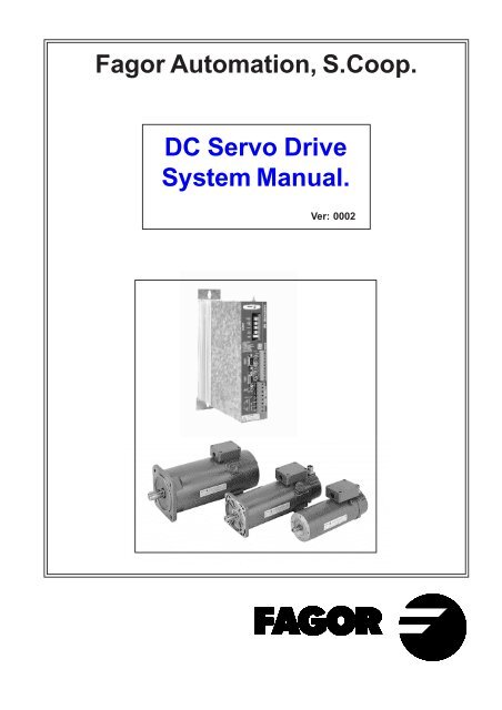
<strong>Fagor</strong> <strong>Automation</strong>, S.<strong>Coop</strong>.<br />
<strong>DC</strong> <strong>Servo</strong> <strong>Drive</strong> <strong>System</strong> <strong>Manual</strong> Ver: 0002<br />
<strong>DC</strong> <strong>Servo</strong> <strong>Drive</strong><br />
<strong>System</strong> <strong>Manual</strong>.<br />
Ver: 0002<br />
<strong>DC</strong> - 1
<strong>DC</strong> - 2<br />
Index<br />
<strong>DC</strong> Motors, <strong>DC</strong>M 4<br />
1.1 INTRODUCTION........................................................................................................................... 4<br />
1.2 GENERAL CHARACTERISTICS .................................................................................................. 5<br />
1.3 TORQUE-SPEED CURVES......................................................................................................... 6<br />
1.4 TERMINAL BOX........................................................................................................................... 7<br />
1.5 ENCODER OUTPUT CONNECTOR ............................................................................................. 7<br />
1.6 CHARACTERISTICS PLATE AND SALES REFERENCE............................................................. 8<br />
1.7 SERVICE INSTRUCTIONS........................................................................................................... 8<br />
D.C. <strong>Servo</strong>drive 9<br />
2.1 INTRODUCTION........................................................................................................................... 9<br />
2.2 GENERAL CHARACTERISTICS .................................................................................................10<br />
2.3 CONNECTORS...........................................................................................................................11<br />
2.4 STATUS DISPLAY......................................................................................................................13<br />
2.5 INTERNAL OPERATION DIAGRAM ............................................................................................14<br />
2.6 SPECIFICATIONS PLATE AND SALES REFERENCE................................................................15<br />
Motor-<strong>Drive</strong> set 17<br />
Identity Module, IM 18<br />
Installation 21<br />
5.1 GENERAL CONSIDERATIONS...................................................................................................21<br />
5.2 ELECTRICAL CONNECTIONS....................................................................................................22<br />
5.3 ELECTRICAL ENCLOSURE DIAGRAM ......................................................................................26<br />
5.4 INITIALIZATION AND SETUP ......................................................................................................27<br />
Mechanicals Dimensions 28<br />
<strong>DC</strong> <strong>Servo</strong> <strong>Drive</strong> <strong>System</strong> <strong>Manual</strong> Ver: 0002
<strong>DC</strong> <strong>Servo</strong> <strong>Drive</strong> <strong>System</strong> <strong>Manual</strong> Ver: 0002<br />
Introduction<br />
<strong>Fagor</strong> offers you a wide range of servo drive systems (motor and drive) for applications requiring<br />
between 1 and 12 Nm at speeds between 1200 rpm and 4000 rpm.<br />
This manual describes the elements in detail and guides step by step through the installation and<br />
setup of the drive system.<br />
When installed for the first time, it is a good idea to read the whole document.<br />
Should you have any doubts or questions, please do not hesitate to contact our technicians at any<br />
of our subsidiaries worldwide.<br />
Thank you for choosing <strong>Fagor</strong>.<br />
Declaration of conformity<br />
Manufacturer: <strong>Fagor</strong> <strong>Automation</strong>, S. <strong>Coop</strong>.<br />
Barrio de San Andrés s/n, C.P. 20500, Mondragón -Guipúzcoa- (SPAIN)<br />
We hereby declare, under our responsibility that the product:<br />
<strong>Fagor</strong> <strong>DC</strong> <strong>Servo</strong> <strong>Drive</strong> <strong>System</strong>.<br />
consisting of the following modules and motors:<br />
<strong>Servo</strong>drives: <strong>DC</strong>S Series<br />
<strong>DC</strong> Motors: <strong>DC</strong>M Series<br />
mentioned on this declaration,<br />
with the basic requirements of the European Directives 73/23/CE on Low Voltage (Basic Safety<br />
Regulation, Machinery Electrical Equipment EN60204-1:95) and 89/336/CE on Electromagnetic<br />
Compatibility (EN 61800-3:1996, Specific Regulation on Electromagnetic Compatibility for <strong>Servo</strong><br />
<strong>Drive</strong> <strong>System</strong>s).<br />
In Mondragón, February 15th, 2000<br />
<strong>DC</strong> - 3
<strong>DC</strong> - 4<br />
<strong>DC</strong>M5<br />
1.1 INTRODUCTION<br />
<strong>Fagor</strong> <strong>DC</strong>M motors (<strong>DC</strong>) are<br />
especially designed to be<br />
controlled by <strong>Fagor</strong> <strong>DC</strong><br />
servo drives.<br />
These <strong>DC</strong> motors are easier<br />
and less expensive to govern<br />
than brushless motors, they<br />
output a torque with less<br />
ripple and its mechanics is<br />
an industrial standard.<br />
(*) The diagram below shows<br />
the meaning of the mounting<br />
codes.<br />
B14/B5 V18/V1 V19/V3<br />
<strong>DC</strong> Motors, <strong>DC</strong>M<br />
<strong>DC</strong>M4 <strong>DC</strong>M2<br />
Winding voltage 100-130 Vdc<br />
Number of poles 2 (<strong>DC</strong>M2); 4 (<strong>DC</strong>M4 and <strong>DC</strong>M5)<br />
Shaft end Cylindrical with keyway.<br />
Mounting Face flange.<br />
(meets IEC-34- 7-72) B14, V18, V19 on <strong>DC</strong>M2;<br />
B5, V1, V3 on <strong>DC</strong>M4 and <strong>DC</strong>M5.<br />
Mechanical tolerance Standard class (meets IEC 72/1971)<br />
Bearings life 10000 hours<br />
Balancing Class N (meets DIN 45665)<br />
(balancing with keyway)<br />
Noise Meets IEC 34-9-72<br />
Brake (optional) 24 Vdc<br />
Insulation Class F and H<br />
Degree of protection IP44 (**)<br />
Operating temperature range From 0°C to +40°C (32°F to 104°F)<br />
Maximum overtemperature 130°C (266°F)<br />
Thermal switch N. C. 120°C (248°F)<br />
13 Amp (250 Vac); 18 Amp (24 Vdc)<br />
Maximum altitude 1000 meters (1281 ft) above sea level.<br />
Feedback 20 Volt/Krpm tachometer<br />
2500 lines/turn encoder TTL<br />
(**) IP44 means that it is protected against particles with<br />
a diameter greater than 1 mm and against water splashes<br />
in all directions.<br />
<strong>DC</strong> <strong>Servo</strong> <strong>Drive</strong> <strong>System</strong> <strong>Manual</strong> Ver: 0002
<strong>DC</strong> <strong>Servo</strong> <strong>Drive</strong> <strong>System</strong> <strong>Manual</strong> Ver: 0002<br />
<strong>DC</strong> - 5<br />
1.2 GENERAL<br />
CHARACTERISTICS<br />
rad/s 2<br />
MOTOR PARAMETERS<br />
UNIT<br />
<strong>DC</strong>M21<br />
21.40A<br />
Continuous stall torque<br />
(1) Nm<br />
1,12<br />
Peak stall torque<br />
Nm<br />
4,7<br />
Rated torque Nm 0,9<br />
Rated power Kw 0,37<br />
Mechanical time constant<br />
ms<br />
28,8<br />
Electrical time constant<br />
ms<br />
4,8<br />
Theoretical acceleration at peak torque<br />
4.950<br />
THERMAL PARAMETERS<br />
Thermal time constant<br />
ELECTRICAL PARAMETERS<br />
Torque constant (KT) (2)<br />
Voltage constant<br />
Armature resistance w/o brushes<br />
Armature resistance with brushes<br />
Armature inductance<br />
Back EMF<br />
Continuous stall current<br />
Peak current<br />
Maximum speed<br />
MECHANICAL PARAMETERS<br />
Inertia<br />
(2)<br />
Total weight with tachometer<br />
min<br />
Nm/A<br />
(2) V/(rad/s)<br />
(2) ohms<br />
(2) ohms<br />
(2)<br />
mH<br />
V<br />
A<br />
A<br />
rpm<br />
(Kg·m 2 )·10E-3<br />
Kg<br />
45<br />
0,24<br />
0,24<br />
1,6<br />
1,75<br />
8,5<br />
103<br />
4,7<br />
19,5<br />
4.000<br />
0,95<br />
5,2<br />
<strong>DC</strong>M2<br />
<strong>DC</strong>M22 <strong>DC</strong>M23<br />
22.40A<br />
2,2 3,1<br />
10 14<br />
1,5 2<br />
0,62 0,52<br />
20<br />
5,7<br />
5.555<br />
55<br />
0,25<br />
0,25<br />
0,55<br />
0,7<br />
4<br />
105<br />
8,8<br />
40<br />
4.000<br />
1,8<br />
21,2<br />
5<br />
5.185<br />
60<br />
0,43<br />
0,43<br />
1,2<br />
1,4<br />
7<br />
113<br />
7,2<br />
32,5<br />
2.500<br />
2,7<br />
7,3 9,5<br />
23.25A<br />
BRAKE PARAMETERS<br />
<strong>DC</strong>M2 <strong>DC</strong>M4 <strong>DC</strong>M5<br />
Power Supply voltage, (power)<br />
Vdc, (W) 24, (12) 24, (15) 24, (25)<br />
Hold/Release time sec 5/7 7/15 18/55<br />
Inertia Kg.cm<br />
Parking torque<br />
Nm<br />
2 5 20<br />
Brake mass<br />
Kg<br />
0,6 1 3<br />
2 0.38 1.05 8.5<br />
(1) Ambient temperature: 40°C<br />
(2) Tolerance ±10 %<br />
(3) Peak-to-peak value / average value.<br />
Measured with filter at max. motor speed<br />
16<br />
3,5<br />
9.190<br />
0,88 0,53<br />
0,88<br />
5,80<br />
5,90<br />
21<br />
110,5<br />
2,9<br />
22<br />
<strong>DC</strong>M41<br />
41.12A 41.20A 41.30A<br />
2,6 2,5 2,4<br />
19,3 19,3 19,3<br />
2,3 2 1,6<br />
0,29 0,42 0,5<br />
14,2<br />
3,9<br />
9.190<br />
50<br />
0,53<br />
1,80<br />
1,90<br />
7,5<br />
111<br />
4,7<br />
36,5<br />
1.200 2.000 3.000 1.200<br />
2,1<br />
9,3<br />
13,7<br />
4,3<br />
9.190<br />
0,35 0,88<br />
0,35<br />
0,70<br />
0,80<br />
3,5<br />
110<br />
6,9<br />
55<br />
9.687<br />
0,88<br />
2,5<br />
2,6<br />
13<br />
110,5<br />
5,2<br />
35<br />
TACHOMETER PARAMETERS -T0-<br />
<strong>DC</strong>M4<br />
<strong>DC</strong>M42<br />
42.12A 42.20A 42.30A 43.12A 43.20A 43.30A 51.12A<br />
4,6 4,4 4,2 7,2 7,0 6,8<br />
9,5<br />
31 29 31 54 54 54<br />
50<br />
4,5 4 3,5 6,8 5,5 4<br />
8<br />
0,56 0,83 1,1 0,85 1,15 1,25 1<br />
10,7 11,1 11,7 6,8 8,8 8,7<br />
10,4<br />
5 5,1 4,4 7,5 5,5 6<br />
6<br />
9.687<br />
60<br />
0,56<br />
0,56<br />
0,9<br />
0,98<br />
5<br />
118<br />
7,8<br />
52<br />
2.000<br />
3,2<br />
12,4<br />
Voltage Gradient<br />
V / Krpm<br />
Voltage Ripple (3) %<br />
Armature resistance<br />
(2) ohms<br />
Temperature coefficient<br />
% / °C<br />
Minimum load resistance value Kohms<br />
9.687<br />
0,38<br />
0,38<br />
0,38<br />
0,45<br />
2<br />
120<br />
11,0<br />
80<br />
3.000<br />
11.250<br />
0,98<br />
0,98<br />
1,12<br />
1,22<br />
9<br />
123<br />
7,3<br />
55<br />
1.200<br />
20 ± 5%<br />
1.3 TORQUE-SPEED CURVES<br />
Nm<br />
50<br />
10<br />
5<br />
1<br />
1<br />
0.5<br />
0 1000 rpm 3000 4000<br />
Nm<br />
100<br />
50<br />
20<br />
10<br />
5<br />
3<br />
<strong>DC</strong> - 6<br />
<strong>DC</strong>M21 Nm <strong>DC</strong>M22 Nm <strong>DC</strong>M23<br />
50<br />
50<br />
<strong>DC</strong>M41<br />
2<br />
1<br />
1<br />
0rpm1000<br />
1200 2000 3000<br />
Nm<br />
300<br />
100<br />
50<br />
10<br />
1<br />
3<br />
2<br />
<strong>DC</strong>M52<br />
3<br />
2<br />
1<br />
0 rpm 1000 1200 2000 3000<br />
2<br />
10<br />
5<br />
1<br />
1<br />
0.5<br />
0 1000 rpm 3000 4000<br />
Nm<br />
100<br />
50<br />
20<br />
10<br />
5<br />
3<br />
<strong>DC</strong>M42<br />
2<br />
1<br />
1<br />
0rpm1000<br />
1200 2000 3000<br />
Nm<br />
300<br />
100<br />
50<br />
10<br />
1<br />
3<br />
2<br />
1<br />
LS<br />
3<br />
2<br />
<strong>DC</strong>M52<br />
0 rpm 1000 1200 2000 3000<br />
2<br />
10<br />
5<br />
1<br />
1<br />
0.5<br />
0 1000 rpm 2500 3000<br />
Nm<br />
100<br />
50<br />
20<br />
10<br />
5<br />
3<br />
<strong>DC</strong>M43<br />
2<br />
1<br />
1<br />
0rpm1000<br />
1200 2000 3000<br />
1. Work area in continuous<br />
duty cycle S1. Torque<br />
available in continuous<br />
mode.<br />
2. Work area in intermittent<br />
duty cycle. Torque available<br />
in cyclic acceleration and<br />
deceleration.<br />
3. Work area in sporadic<br />
acceleration and<br />
deceleration. Working in this<br />
area, reduces the life span<br />
of the brushes.<br />
L.S. Demagnetizing limit at 25°C (77°F). The <strong>DC</strong>S drive, equipped with the proper IM board, watches<br />
the motor so it never exceeds those demagnetizing currents.<br />
<strong>DC</strong> <strong>Servo</strong> <strong>Drive</strong> <strong>System</strong> <strong>Manual</strong> Ver: 0002<br />
2<br />
3<br />
2
1.4 TERMINAL BOX<br />
Includes terminals for:<br />
Power input for the motor winding. Input for electromechanical brake<br />
Tacho voltage output. Safety thermal contact<br />
Tacho<br />
D<br />
Thermal C<br />
Ch.<br />
CWR<br />
Clockwise Rotation<br />
Brake<br />
E<br />
B Motor<br />
Power<br />
When the motor winding is supplied with the polarity indicated on the terminal box (B+, E-), the<br />
rotor turns clockwise (CWR, clockwise rotation), as shown in the diagram. And, for this turning<br />
direction, the tacho generates a voltage at its terminals (Tacho) also with the polarity indicated on<br />
the box (+, -).<br />
The electromechanical brake releases the motor shaft when applied 24 Vdc.<br />
When stationary, it holds the motor shaft.<br />
The thermal switch watches the armature winding temperature.<br />
<strong>DC</strong> <strong>Servo</strong> <strong>Drive</strong> <strong>System</strong> <strong>Manual</strong> Ver: 0002<br />
B<br />
Motor<br />
Power<br />
E<br />
Brake<br />
1.5 ENCODER OUTPUT CONNECTOR<br />
TTL Encoder<br />
<strong>DC</strong> Motor<br />
1<br />
2<br />
3 +5V<br />
4<br />
5<br />
6<br />
7<br />
8<br />
9<br />
*A<br />
Pin Signal<br />
A<br />
0V<br />
B<br />
*B<br />
Z<br />
*Z<br />
NC<br />
Front View<br />
1 8<br />
2<br />
9<br />
7<br />
3 6<br />
4 5<br />
M<br />
CWR<br />
Clockwise Rotation<br />
G<br />
A<br />
B<br />
Z<br />
N.C.<br />
D<br />
Thermal<br />
C<br />
Ch.<br />
Tacho<br />
Clockwise Rotation (CWR)<br />
signals:<br />
t<br />
<strong>DC</strong> - 7
1.6 CHARACTERISTICS PLATE AND SALES REFERENCE<br />
Example of the plate that<br />
comes with each <strong>DC</strong>M motor.<br />
Sales reference description<br />
for <strong>DC</strong>M motors<br />
1.7 SERVICE INSTRUCTIONS<br />
The brushes must be checked for the first time after being running for 500 hours and, then, every<br />
1000 hours. One must check the way they sweep, their surface and that of the collector.<br />
The life span of the brushes depend on how they are used and on ambient conditions.<br />
They must be replaced with brushes of same quality and dimensions: 10 mm for the <strong>DC</strong>M2, and<br />
11 mm for the <strong>DC</strong>M4 and <strong>DC</strong>M5.<br />
<strong>DC</strong> - 8<br />
Permanent Magnet D.C. <strong>Servo</strong>motor<br />
TYPE: <strong>DC</strong>M42.20A.E0.000<br />
SN: E190057 KT: 0.56 Nm/A Iso.Cl.: F<br />
Mo 4.4 Nm Io: 7.8 A MAX. RPM: 2000<br />
Mp 29 Nm Ip: 52 A B.E.M.F.: 118 V<br />
TACHO: V/KRPM BRAKE: V A<br />
<strong>DC</strong> MOTORS Example <strong>DC</strong>M 4 2. 20 A. E0. 0 0 0<br />
DIRECT CURRENT MOTOR<br />
MOTOR SIZE 2 95 mm<br />
4 115 mm<br />
5 153 mm<br />
LENGTH 1, 2, 3 See drawings<br />
MAXIMUM SPEED 12 1200 rpm 30 3000 rpm<br />
20 2000 rpm 40 4000 rpm<br />
25 2500 rpm<br />
WINDING A Standard<br />
FEEDBACK E0 TTL Encoder (standard)<br />
T0 Tacho<br />
F0 Encoder and Tacho (not available)<br />
FLANGE AND SHAFT 0 With keyway (standard)<br />
1 Without keyway<br />
BRAKE OPTION 0 Without brake (standard)<br />
1 With brake (24 Vdc)<br />
POWER CONNECTION 0 Terminal box<br />
1 Power connector (not available)<br />
<strong>DC</strong> <strong>Servo</strong> <strong>Drive</strong> <strong>System</strong> <strong>Manual</strong> Ver: 0002
2.1 INTRODUCTION<br />
<strong>DC</strong> <strong>Servo</strong> <strong>Drive</strong> <strong>System</strong> <strong>Manual</strong> Ver: 0002<br />
D.C. <strong>Servo</strong>drive<br />
The D.C.<strong>Servo</strong> drive is a compact speed drive which<br />
includes the power supply and is designed to control a<br />
single <strong>DC</strong> motor.<br />
There are two modules of different power offering rated<br />
currents of 8 and 14 Amps and whose main characteristics<br />
are:<br />
- Three-phase power supply through a transformer.<br />
- PWM Mosfets.<br />
- Encoder feedback (standard) or tacho.<br />
- Velocity or Torque command.<br />
- Velocity command filtered with ramps.<br />
- Logic inputs to control the motor.<br />
- Galvanic isolation between power and control<br />
- Analog outputs to monitor speed and current.<br />
- Control against excessive acceleration/deceleration.<br />
- Dynamic braking during mains failures.<br />
- Protection against motor current drifts.<br />
- Protection against feedback loss.<br />
- Protection against excessive temperature, Bus voltage and output current.<br />
- 7-segment display to monitor the status of the servo drive system.<br />
<strong>DC</strong> - 9
2.2 GENERAL CHARACTERISTICS<br />
Maximum peak current.<br />
The drive withstands a maximum peak current in repetitive cycles<br />
The first graph shows the duty cycle analyzed on a motor without load.<br />
The following graph shows the maximum peak current allowed at the <strong>DC</strong>S depending on the<br />
duration of the pulse and for different temperatures.<br />
In any case, the duration of the maximum current pulse (T1) must not exceed 4.5 seconds.<br />
<strong>DC</strong> - 10<br />
+rpm<br />
-rpm<br />
T1<br />
T2<br />
Amp<br />
18<br />
16<br />
14<br />
12<br />
10<br />
8<br />
6<br />
0<br />
Amp<br />
30<br />
25<br />
20<br />
15<br />
10<br />
5<br />
0<br />
0.1<br />
0.1<br />
<strong>Fagor</strong> D.C.<strong>Servo</strong>drive<br />
<strong>DC</strong>S-08 <strong>DC</strong>S-14<br />
Power supply 110 Vac between phases. 50/60 Hz<br />
(range 94-120 Vac)<br />
Consumption, Amperes -RMS- 9 16<br />
Maximum in-rush current 350 Amp for 10 msec.<br />
Maximum output voltage 150 Vdc<br />
Rated output current 8 Amp 14 Amp<br />
Peak current (4.5 sec) 16 Amp 28 Amp<br />
Overvoltage protection 192 V<br />
Overcurrent protection 20 A 33 A<br />
Internal Ballast 10 Ohms, 200 W<br />
Ballast trigger 184 V<br />
Thermal protection 90°C (194°F)<br />
Ambient temperature 5°C / 45°C (41°F / 113°F)<br />
Storage temperature -20°C / 60°C (-4°F / 140°F)<br />
Insulation IP20 (*)<br />
Module width 62 x 300 x 230 mm<br />
(2.48 x 11.8 x 9.05 inches)<br />
Module weight 3,5 Kg (7.76 lbs)<br />
(*) IP20 means that it is protected against particles with diameter greater than 12.5 mm; but not<br />
against water splashes. In other words, the equipment must be mounted inside the electrical<br />
enclosure.<br />
<strong>DC</strong>S-08<br />
45°C<br />
0.2 0.3<br />
T1/T2<br />
0.4 0.5 0.6<br />
<strong>DC</strong>S-14<br />
45°C<br />
25°C<br />
25°C<br />
0.2 0.3<br />
T1/T2<br />
0.4 0.5 0.6<br />
<strong>DC</strong> <strong>Servo</strong> <strong>Drive</strong> <strong>System</strong> <strong>Manual</strong> Ver: 0002
2.3 CONNECTORS<br />
Power Terminals<br />
Motor Output: ±150 Vdc output voltage applied to the motor<br />
Output current to the motor (continuous/peak for 4.5 seconds):<br />
<strong>DC</strong>S-08: 8A/16A<br />
<strong>DC</strong>S-14: 14A/28A<br />
Maximum current with PWM on a carrier frequency of 10 kHz.<br />
Watch out for polarity. See page 23.<br />
Power Input: 94-120Vac three-phase supply through a transformer. See page 22.<br />
The maximum cable section at these power terminals is: 2.5 mm 2 .<br />
Total isolation between power and control circuits.<br />
Control Signals<br />
±10V voltages, Pins 1,2,3: Internal power supply so the user can easily generate a velocity<br />
command. It offers a maximum current of 20mA limited internally.<br />
Velocity command. Pins 4,5,6:<br />
Current command. Pins 4,7:<br />
See page 25. The motor torque is directly proportional to the current. "Torque command".<br />
Tacho feedback. Pins 8,9: Velocity feedback input from the tacho into the drive. Be careful with<br />
the polarity. See page 24.<br />
Monitoring. Pins 10,11,12: Voltage outputs for monitoring motor speed and current. Voltage<br />
range of ±10V. See page 23.<br />
Common, Pin 15: Reference point for the following Enable signals:<br />
<strong>Drive</strong> Enable, Pin 14: At 0Vdc, disables current through the motor which loses its torque.<br />
Speed Enable, Pin 13: A 0Vdc, forces a "zero speed" command.<br />
These control signals are activated at +24Vdc.<br />
<strong>Drive</strong> OK. Pins 16,17: Relay contact that closes when the internal status of the drive is OK. It<br />
must be included in the electrical manoeuver. See page 26.<br />
Encoder Input: Encoder signal input to the motor for velocity feedback.<br />
Encoder Output: Encoder output for closing the loop at the CNC. See page 24.<br />
The maximum section for these cables is 0.5 mm 2 .<br />
<strong>DC</strong> <strong>Servo</strong> <strong>Drive</strong> <strong>System</strong> <strong>Manual</strong> Ver: 0002<br />
<strong>DC</strong> - 11
Front panel and<br />
Connectors.<br />
Meaning of the<br />
possible messages<br />
at the Status display.<br />
Encoder output<br />
connector for the<br />
CNC.<br />
<strong>DC</strong> - 12<br />
1 234<br />
5<br />
6<br />
7 8<br />
3<br />
4<br />
5<br />
6<br />
21<br />
9<br />
11<br />
15<br />
A<br />
*A B<br />
*B<br />
Z<br />
*Z<br />
11 0 V<br />
A<br />
*A<br />
B<br />
*B<br />
Z*Z<br />
+5V<br />
0V<br />
Encoder feedback<br />
input connector.<br />
ADJUST<br />
Acc/Dec.<br />
Ramps<br />
Max.<br />
Current<br />
Limit<br />
PI.Gain<br />
Max.<br />
Speed<br />
Offset<br />
. DRIVE DISABLED<br />
0 SPEED DISABLED<br />
1 RUNNING<br />
2 MOTOR INSULATION FAULT<br />
3 FEEDBACK ERROR<br />
4 DRIVE OVERTEMPERATURE<br />
5 MOTOR OVERLOAD<br />
6 DRIVE OVERCURRENT<br />
7 DRIVE OVERVOLTAGE<br />
E UNDERVOLTAGE<br />
ENCODER<br />
OUTPUT<br />
ENCODER<br />
INPUT<br />
MOTOR<br />
OUTPUT<br />
POWER<br />
INPUT<br />
3x110Vac.<br />
M<br />
L1<br />
L2<br />
L3<br />
DANGER<br />
20mA out<br />
COMMANDS<br />
ENABLES MONITOR<br />
DR.OK<br />
Not<br />
Connected<br />
-10V<br />
+10V<br />
VEL+<br />
VEL-<br />
CURR<br />
VELOCITY<br />
CURRENT<br />
SPEED<br />
DRIVE<br />
COMMON<br />
HIGH VOLTAGE 150Vdc<br />
DISCHARGE TIME = 1 min.<br />
T<br />
1<br />
2<br />
3<br />
4<br />
5<br />
6<br />
7<br />
8<br />
9<br />
10<br />
11<br />
12<br />
13<br />
14<br />
15<br />
16<br />
17<br />
<strong>DC</strong> <strong>Servo</strong>drive<br />
STATUS<br />
CONTROL - SIGNALS<br />
POWER TERMINALS<br />
Identity module: IM.<br />
- See corresponding section -<br />
<strong>Drive</strong> status display.<br />
-10 V<br />
+10 V<br />
VEL+<br />
VEL-<br />
CURR<br />
VELOCITY<br />
CURRENT<br />
SPEED<br />
DRIVE<br />
COMMON<br />
DR.OK<br />
MOTOR<br />
OUTPUT<br />
POWER<br />
INPUT<br />
Connector for drive<br />
control signals.<br />
L1<br />
L2<br />
L3<br />
10<br />
11<br />
12<br />
13<br />
14<br />
15<br />
16<br />
17<br />
<strong>DC</strong> <strong>Servo</strong> <strong>Drive</strong> <strong>System</strong> <strong>Manual</strong> Ver: 0002<br />
1<br />
2<br />
3<br />
4<br />
5<br />
6<br />
7<br />
8<br />
9<br />
±10 V<br />
power<br />
supply.<br />
Commands.<br />
Tacho<br />
feedback.<br />
Monitoring.<br />
Enables.<br />
<strong>Drive</strong> OK.<br />
Power terminals<br />
to supply current<br />
to the motor.<br />
Power terminals<br />
to get energy from<br />
mains.
2.4 STATUS DISPLAY<br />
It is a 7-segment display for monitoring the <strong>Drive</strong> status.<br />
The unit is under power, the "<strong>Drive</strong> Enable" pin is deactivated, (0 Volts at pin 14).<br />
The motor has no torque.<br />
"Speed Enable" off (0 Volts at pin 13), and "<strong>Drive</strong> Enable" (+24V at pin 14).<br />
The motor has torque with no velocity command.<br />
Everything is OK. "<strong>Drive</strong> Enable" and "Speed Enable" are active and the Motor responds to<br />
the command.<br />
Current leak from power lines to ground.<br />
Solutions: carry out the motor maintenance procedures. Check the insulation of the power<br />
cables.<br />
No Feedback.<br />
Solutions: Check that jumper J1 selects the feedback mode being used. Check that the<br />
feedback cable and connectors are properly connected. Check that the winding circuit is not<br />
open. When working in velocity command mode, make sure that jumper J4 is in the (bc)<br />
position. When working in torque command mode, make sure that the RAPT resistor of the<br />
identity module is short-circuited.<br />
In the case of an Encoder, check the polarity of the voltage applied to the winding and that<br />
the signal pairs (A,*A) and (B,*B) are not interchanged.<br />
In the case of tacho feedback, check the polarity of the winding and that of the tacho. Check<br />
that the tacho is not open or defective.<br />
<strong>Drive</strong> overtemperature.<br />
Solutions: Smooth the duty cycle. Improve its cooling. The unit will return to its normal running<br />
status when it cools down below 78°C (172°F).<br />
Motor overload. The I·T protection has gone off. In other words, the motor has maintained an<br />
average current greater than the maximum allowed (Iomax M ) for too long. The duty cycle is<br />
too demanding for the capabilities of the motor. The motor is working beyond its rated<br />
current.<br />
Solutions: Smooth the duty cycle. Limit motor acceleration with ACC/DEC RAMPS. Limit the<br />
commands, MAX.CURRENT LIMIT and MAX.SPEED. Decrease the RIT, thus allowing the<br />
system to further force the motor.<br />
Overcurrent. There has been an instantaneous current peak greater than the maximum allowed<br />
according to the table on page 11.<br />
Solutions: Limit motor acceleration with ACC/DEC RAMPS. If the motor has low inductance and<br />
the current ripple is excessive, add an inductance in series with the winding circuit (this is<br />
never required with <strong>Fagor</strong> <strong>DC</strong>M motors).<br />
Overvoltage. For an instant, the internal Bus voltage has exceeded 193 V.<br />
Solutions: The Ballast circuit may be defective or the supply voltage is too high.<br />
Low-voltage. The supply voltage is too low.<br />
Notes:<br />
All the alarms except the 4. and E. are latched and the unit must be powered off and, after 30<br />
seconds, turned back on.<br />
J1, J4, RAPT, ACC/DEC RAMPS, MAX.CURRENT LIMIT, MAX.SPEED and RIT are elements for<br />
adjusting the servo drive system and they are described in the section on "the Identity Module IM".<br />
<strong>DC</strong> <strong>Servo</strong> <strong>Drive</strong> <strong>System</strong> <strong>Manual</strong> Ver: 0002<br />
<strong>DC</strong> - 13
<strong>DC</strong> - 14<br />
<strong>DC</strong> <strong>Servo</strong> <strong>Drive</strong> <strong>System</strong> <strong>Manual</strong> Ver: 0002<br />
POWER<br />
INPUT<br />
VEL<br />
VEL<br />
CURR<br />
Pin 5<br />
Pin 6<br />
ENCODER<br />
OUTPUT<br />
ENCODER<br />
INPUT<br />
L1<br />
L2<br />
L3<br />
Pin 7<br />
Pin 4<br />
Pin 8<br />
TACHO<br />
INPUT<br />
Pin 9<br />
A<br />
Ramp<br />
generator<br />
Acc/Dec<br />
Ramps<br />
Max.<br />
Speed<br />
Rectifer<br />
a b c d e<br />
Ballast.<br />
J1<br />
Speed PI<br />
PI. Gain<br />
Internal<br />
supply<br />
b<br />
J3<br />
a<br />
Pin 1<br />
Pin 2<br />
Pin 3<br />
-10V<br />
+10V<br />
Max. Current<br />
Limit<br />
Protections:<br />
Motor Insulation Fault<br />
Feedback Error<br />
<strong>Drive</strong> Overtemperature<br />
Motor Overload<br />
<strong>Drive</strong> Overcurrent<br />
<strong>Drive</strong> Overvoltage<br />
Undervoltage<br />
Power<br />
stage.<br />
PWM<br />
Logic circuits for<br />
diagnosis & control.<br />
MOTOR<br />
OUTPUT<br />
SPEED<br />
COMMON<br />
Pin 13<br />
Pin 15<br />
Overspeed<br />
Pin 14<br />
DRIVE<br />
COMMON<br />
Pin 15<br />
J2 a b c<br />
Control<br />
A<br />
Frequency / Voltage<br />
RAJFV<br />
RTV1<br />
Power-down<br />
detection<br />
Offset<br />
RAD1<br />
CAD1<br />
RAP1<br />
CAI1<br />
RIT<br />
RAPT<br />
c<br />
b<br />
a<br />
J4<br />
Bus<br />
Voltage<br />
Current<br />
PI<br />
PWM<br />
Control<br />
Bus<br />
Voltage<br />
Pin 12<br />
CURRENT<br />
Pin 11<br />
VELOCITY<br />
Pin 16<br />
Pin 17<br />
STATUS<br />
DR.OK<br />
2.5 INTERNAL<br />
OPERATION<br />
DIAGRAM
2.6 SPECIFICATIONS PLATE AND SALES REFERENCE<br />
Examples of the specs plate<br />
that comes with each <strong>Fagor</strong><br />
<strong>DC</strong> drive.<br />
Codes of the sales<br />
reference of <strong>Fagor</strong> <strong>DC</strong><br />
drives.<br />
<strong>DC</strong> <strong>Servo</strong> <strong>Drive</strong> <strong>System</strong> <strong>Manual</strong> Ver: 0002<br />
MODEL: <strong>DC</strong>S-14-E0<br />
S.N.: 22-19040001<br />
PM<br />
00A<br />
FV<br />
00A<br />
VAR<br />
00A<br />
<strong>Fagor</strong> <strong>Automation</strong> S. <strong>Coop</strong>.(Spain)<br />
<strong>DC</strong> SERVODRIVE<br />
"PM", "FV", "VAR" and "FR" indicate manufacturing related aspects (hardware design versions)<br />
that are useful for technical consultations and repairs.<br />
FR<br />
MODEL: <strong>DC</strong>S-08-T0<br />
S.N.: 22-19040000<br />
PM<br />
00A<br />
VAR<br />
00A<br />
FR<br />
INPUT :<br />
OUTPUT:<br />
Io<br />
Imax<br />
3 X 110 VAC / 50-60 Hz<br />
0-150 V<strong>DC</strong><br />
D.C. SERVODRIVES Example: <strong>DC</strong>S - 08 - E0<br />
D.C. SERVODRIVE<br />
CURRENT Rated Peak (4.5 sec)<br />
08 8 Amp 16 Amp<br />
14 14 Amp 28 Amp<br />
FEEDBACK T0 Basic drive. Ready to<br />
control motors with tacho<br />
E0 <strong>Drive</strong> especially equipped<br />
to also control motors<br />
with Encoder (E0 and F0). Standard.<br />
14<br />
28<br />
Amp<br />
Amp<br />
W: 3,5 Kg<br />
<strong>Fagor</strong> <strong>Automation</strong> S. <strong>Coop</strong>.(Spain)<br />
<strong>DC</strong> SERVODRIVE<br />
INPUT :<br />
OUTPUT:<br />
Io<br />
Imax<br />
8<br />
16<br />
3 X 110 VAC / 50-60 Hz<br />
0-150 V<strong>DC</strong><br />
Amp<br />
Amp<br />
W: 3,5 Kg<br />
<strong>DC</strong> - 15
Rated and peak torque<br />
<strong>DC</strong> <strong>Servo</strong> <strong>Drive</strong> <strong>System</strong> <strong>Manual</strong> Ver: 0002<br />
Motor-<strong>Drive</strong> set<br />
The characteristics of rated and peak torques of the motors are often limited by the current<br />
capabilities of the <strong>Drive</strong> controlling them.<br />
This table considers these possible limitations.<br />
<strong>DC</strong>S-08 DRIVE <strong>DC</strong>S-14 DRIVE<br />
Speed Stall Torque Peak Torque Stall Torque Peak Torque<br />
MOTORS -rpm- -Nm- -Nm- -Nm- -Nm-<br />
<strong>DC</strong>M21.40A 4000 1.12 3.8<br />
<strong>DC</strong>M22.40A 4000 2 4 2.2 7<br />
<strong>DC</strong>M23.25A 2500 3.1 6.8 3.1 12<br />
<strong>DC</strong>M41.12A 1200 2.6 15.2<br />
<strong>DC</strong>M41.20A 2000 2.5 8.5<br />
<strong>DC</strong>M41.30A 3000 2.4 5.6<br />
<strong>DC</strong>M42.12A 1200 4.6 15.2<br />
<strong>DC</strong>M42.20A 2000 4.4 8.9 4.4 15.6<br />
<strong>DC</strong>M42.30A 3000 4.2 10.6<br />
<strong>DC</strong>M43.12A 1200 7.2 15.6 7.2 27.4<br />
<strong>DC</strong>M43.20A 2000 7 16.2<br />
<strong>DC</strong>M43.30A 3000 5.5 10.9<br />
<strong>DC</strong>M51.12A 1200 9.5 28<br />
<strong>DC</strong>M51.20A 2000 8.4 16.8<br />
<strong>DC</strong>M52.12A 1200 12 28<br />
<strong>DC</strong> - 17
This card is inserted into the <strong>DC</strong>S drive module. Its passive components and jumpers adjust the<br />
drive electronics to the <strong>DC</strong>M motor it governs.<br />
There is an IM card for each correct combination of <strong>DC</strong>M motor and <strong>DC</strong>S drive as shown on the<br />
next page. The IM-000 board is used for setting <strong>DC</strong>S <strong>Drive</strong>s with non-<strong>Fagor</strong> motors. The<br />
calculation of the passive components is described on the next pages.<br />
The potentiometers accessible from the outside allow a final adjustment of the servo drive system.<br />
The component layout of this card and their functions are described next.<br />
Passive components:<br />
NC: Empty.<br />
<strong>DC</strong> - 18<br />
Identity Module, IM<br />
Acc/Decc Ramps<br />
Max. Current Limit<br />
PI Gain<br />
Max. Speed<br />
Offset<br />
RIT: It sets the current value from which the I·T protection starts integrating. If this resistor is<br />
short-circuited, this protection is removed.<br />
RAJFV: When using encoder feedback, it sets the relationship between the frequencies of the<br />
encoder pulses and the equivalent voltage in the internal drive circuits.<br />
RAPT: The system is protected against motor runaway should it lose feedback. This resistor<br />
sets the overspeed value triggering this protection. The smaller the value of the RAPT the more<br />
tolerant the system is. If short-circuited, this protection will be removed. When working in current<br />
command mode, this RAPT must be short-circuited.<br />
abcde<br />
J3 J4<br />
RTV1: It adapts the voltage generated by the tacho to the internal <strong>Drive</strong> circuits.<br />
RAD1, CAD1: They set the derivative compensation at the velocity PI.<br />
RAP1, CAI1: They set the proportional and integral action of the velocity PI.<br />
Jumpers (in bold, default position):<br />
J1: Feedback type selector. Via encoder (bc). Via tacho (de).<br />
J2: Ramp generator, active (ab), or not (bc).<br />
J3: Activates the acceleration overshooting control. Active (ab).<br />
J4: Selector for the type of command. Current command (ab) or velocity (bc).<br />
J1<br />
NC<br />
RIT<br />
RAJFV<br />
RAPT<br />
RTV1<br />
- IM Board -<br />
abc<br />
J2<br />
RAD1<br />
CAD1<br />
RAP1<br />
CAI1<br />
ab abc<br />
<strong>DC</strong> <strong>Servo</strong> <strong>Drive</strong> <strong>System</strong> <strong>Manual</strong> Ver: 0002
These are the names of the identity<br />
modules (IM) for each Motor-<strong>Drive</strong> set.<br />
Adjustment potentiometers:<br />
Acc/Dec Ramps: To adjust the ramp filtering the velocity command. Ramps with a duration of up<br />
to 10 seconds may be applied for a 10 volt step of analog voltage.<br />
Turning this pot clockwise means smoother behavior (longer ramp).<br />
WATCH OUT! If jumper J2 of the identity module is set in the (bc) position, no ramps will be<br />
applied.<br />
Max. Current Limit: Each drive is factory set to provide the maximum current to the motor which<br />
corresponds to the maximum value of the current command. This adjustment may be used to<br />
decrease the value of that current limit.<br />
Turning this pot clockwise allows more current to flow through the motor.<br />
PI Gain: For adjusting the overall gain of the velocity PI.<br />
Turning this pot clockwise increases the gain and, therefore, makes the system perkier.<br />
Max. Speed: Every drive is factory set so the motor turns at its maximum speed when applied<br />
maximum velocity command.<br />
In this case, this pot will be turned 3/4 of its full travel. Therefore, it may be used to limit or force<br />
slightly the maximum motor speed.<br />
Turning this pot clockwise allows greater speed.<br />
Offset: To compensate for the difference between the velocity command and the actual motor<br />
speed.<br />
<strong>DC</strong> <strong>Servo</strong> <strong>Drive</strong> <strong>System</strong> <strong>Manual</strong> Ver: 0002<br />
And these are the values of the passive<br />
components on each of those cards.<br />
IM Board RIT RAJFV RTV1<br />
<strong>DC</strong>S-08 <strong>DC</strong>S-14 <strong>DC</strong>S-08 <strong>DC</strong>S-14<br />
<strong>DC</strong>M21.40A IM-2140A-08 <strong>DC</strong>M21.40A 75K 5,6K 82K<br />
<strong>DC</strong>M22.40A IM-2240A-08 IM-2240A-14 <strong>DC</strong>M22.40A 39K 68K 5,6K 82K<br />
<strong>DC</strong>M23.25A IM-2325A-08 IM-2325A-14 <strong>DC</strong>M23.25A 43K 82K 10K 39K<br />
<strong>DC</strong>M41.12A IM-4112A-08 <strong>DC</strong>M41.12A 130K 22K 10K<br />
<strong>DC</strong>M41.20A IM-4120A-08 IM-4120A-14 <strong>DC</strong>M41.20A 75K 130K 12K 27K<br />
<strong>DC</strong>M41.30A IM-4130A-08 IM-4130A-14 <strong>DC</strong>M41.30A 47K 91K 8,2K 56K<br />
<strong>DC</strong>M42.12A IM-4212A-08 IM-4212A-14 <strong>DC</strong>M42.12A 68K 130K 22K 10K<br />
<strong>DC</strong>M42.20A IM-4220A-08 IM-4220A-14 <strong>DC</strong>M42.20A 39K 75K 12K 27K<br />
<strong>DC</strong>M42.30A IM-4230A-14 <strong>DC</strong>M42.30A 56K 8,2K 56K<br />
<strong>DC</strong>M43.12A IM-4312A-08 IM-4312A-14 <strong>DC</strong>M43.12A 43K 82K 22K 10K<br />
<strong>DC</strong>M43.20A IM-4320A-14 <strong>DC</strong>M43.20A 47K 12K 27K<br />
<strong>DC</strong>M43.30A IM-4330A-14 <strong>DC</strong>M43.30A 39K 8,2K 56K<br />
<strong>DC</strong>M51.12A IM-5112A-14 <strong>DC</strong>M51.12A 62K 22K 10K<br />
<strong>DC</strong>M51.20A IM-5120A-14 <strong>DC</strong>M51.20A 39K 12K 27K<br />
<strong>DC</strong>M52.12A IM-5212A-14 <strong>DC</strong>M52.12A 47K 22K 10K<br />
General purpose: IM-0000 RAPT = 15K RAP1 = 82K CAI1 = 100nF<br />
<strong>DC</strong> - 19
Adjustment of IM components for governing Non-<strong>Fagor</strong> motors<br />
<strong>DC</strong> - 20<br />
RTV1 calculation:<br />
Vmaxtac = Nmax · 1.3 · Ktac<br />
RTV1 = Vmaxtac - 22 (KΩ)<br />
This RTV1 must be of 1/4 Watts<br />
RAJFV calculation:<br />
Example of calculation:<br />
68,4 · 10<br />
RAJFV (KΩ) =<br />
Maximum Speed: 1200 rpm<br />
This RAJFV must be of 1/4 Watt<br />
This calculation is independent of whether the maximum speed is later limited with Max.Speed<br />
or not.<br />
This calculation is OK for velocity commands of ±10V.<br />
If for example, the command is ±8V for a maximum speed of ±1200 rpm, the previous<br />
calculation will result in a maximum speed of 1200·10/8 = 1500 rpm.<br />
6<br />
(Pulses/turn) · Nmax · 1.15<br />
Encoder pulses per turn: 2500<br />
68,4 · 10<br />
RAJFV (KΩ) =<br />
6<br />
= 19.8 KΩ<br />
2500 · 1200 · 1.15<br />
RIT calculation:<br />
RIT (KΩ) =<br />
150<br />
In · K<br />
- 10<br />
This RIT must be of 1/4 Watt<br />
where:<br />
K = 0.39 (<strong>DC</strong>S-8)<br />
K = 0.22 (<strong>DC</strong>S-14)<br />
Example of calculation:<br />
Maximum Speed: 1200 rpm<br />
Tacho Constant: 20 V/Krpm<br />
1200 · 1.3 · 0.02 = 31.2<br />
RTV1 = 31.2 - 22 = 9.2 KΩ / 0.25 W<br />
This calculation is independent of whether the maximum speed is later limited with Max.Speed<br />
or not.<br />
This calculation is OK for velocity commands of ±10V.<br />
If, for example, the command is ±8V for a maximum speed of ±1200 rpm, the previous<br />
calculation will result in 1200·10/8 = 1500 rpm.<br />
Graph for calculating the RTV1 resistor when<br />
using a 20 V/Krpm tacho.<br />
(the one carried by the <strong>Fagor</strong> motors mentioned<br />
in this manual)<br />
Example of calculation:<br />
<strong>DC</strong>S-08 drive<br />
<strong>DC</strong>M41.20 motor : In = 4.72 Amp<br />
RIT (KΩ) =<br />
150<br />
- 10 = 71.5 KΩ<br />
4.72 · 0.39<br />
"In" is the rated current of the motor according to the characteristics table or the current used in<br />
a duty cycle considered nominal.<br />
Codes of the sales reference for the identity cards:<br />
Nmax (rpm)<br />
4000<br />
3000<br />
2000<br />
1000<br />
10<br />
RTV1<br />
(for Ktac = 20 V/Krpm)<br />
20 30 40 50 60 70 80<br />
IDENTITY MODULE Example: IM - 4120A - 14<br />
IDENTITY MODULE<br />
MOTOR TYPE<br />
DRIVE TYPE<br />
RTV1<br />
(kΩ)<br />
<strong>DC</strong> <strong>Servo</strong> <strong>Drive</strong> <strong>System</strong> <strong>Manual</strong> Ver: 0002
5.1 GENERAL CONSIDERATIONS<br />
<strong>DC</strong> <strong>Servo</strong> <strong>Drive</strong> <strong>System</strong> <strong>Manual</strong> Ver: 0002<br />
Insta lation<br />
About the Motor:<br />
Remove the anti-corrosion paint of the shafts before mounting them on to the machine.<br />
The motor may be mounted as described in the first chapter<br />
Watch for the ambient conditions:<br />
Mount it somewhere that is dry, clean and accessible for maintenance.<br />
-remember that it meets the IP44 degree of protection.<br />
It must be easily cooled. Avoid corrosive or flammable environments.<br />
Guard the motor with a cover if it is exposed to splashes.<br />
Use flexible couplings for direct transmission.<br />
Avoid radial and axial loads on the motor shaft.<br />
About the <strong>Drive</strong>:<br />
The module must be installed in an electrical enclosure that is clean, drive free of dust, oil or other<br />
pollutants - remember that its degree of protection is IP20-. Never install it exposing it to flammable<br />
gases. Avoid excessive heat and humidity. The ambient temperature must never exceed 45°C<br />
(113°F).<br />
Mount the modules vertically (as shown on the photos). Avoid vibrations.<br />
Leave at least 30 cm of clearance above and below the module for better air flow.<br />
About the connections:<br />
All the cables must be shielded, to reduce the interference on the control of the motor due to the<br />
commutation of the PWM. The shield of the motor power cable must be connected to the chassis<br />
screw at the bottom of the module and it, in turn, taken to Mains ground.<br />
A transformer MUST BE used. It must serve as a filter to limit the start-up current to the maximum<br />
allowed by the unit. See characteristics on page 10.<br />
The command signal lines must be shielded twisted pairs. The shield must be connected to the<br />
voltage reference at the module (pins 2, 4 or 10).<br />
Keep the signal cables away from the power cables.<br />
All the pins with the GND symbol (2, 4, 10) are the same electrical point and are interchangeable.<br />
Basic interconnection diagram<br />
CNC<br />
SEC Cable<br />
Mains<br />
Ac c/De c .<br />
Ra mps<br />
Max.<br />
Cu rre nt<br />
Lim it<br />
PI.G ain<br />
Max.<br />
Sp eed<br />
Offset<br />
. D RIVE DI SA BLED<br />
0 S PEED D ISA BLED<br />
1 R UNNING<br />
2 MOTOR ISOLATIO N FAUL T<br />
3 F EEDBAC K ERRO R<br />
4 D RIVE OV ERTEM PERATU RE<br />
5 MOTOR OVERLOAD<br />
6 D RIVE OV ERCUR RENT<br />
7 D RIVE OV ERVOL TAGE<br />
E U NDERVO LTAGE<br />
-10V<br />
AD JUST<br />
ENC ODER<br />
OU TPUT<br />
ENC ODER<br />
INPUT<br />
MOT OR<br />
OUT PUTS<br />
1<br />
2<br />
3<br />
+10V<br />
4<br />
5<br />
DIFF +<br />
6<br />
DIFF -<br />
7<br />
CURRENT<br />
8<br />
T 9<br />
10<br />
11<br />
SPEE D<br />
12<br />
CURRENT<br />
13<br />
SPEE D<br />
DRIV E 14<br />
COM MON 15<br />
16<br />
17<br />
PO W ER INP UTS<br />
L1<br />
110 Vac. INPUT<br />
M<br />
3x1 10Vac . INPUT<br />
20 m A o ut<br />
ENAB LES ±10V<br />
DR.O K<br />
L2<br />
L3<br />
L4<br />
DA NGE R<br />
HIG H VO LT AG E 150Vdc<br />
DISC HA RG E TIME > 1 m in.<br />
<strong>DC</strong> <strong>Servo</strong>drive<br />
STATU S<br />
CO NTR OL - SIG NALS<br />
POWER TE RMI NAL S<br />
<strong>DC</strong>S<br />
MPC Cable<br />
<strong>DC</strong>EC Cable<br />
<strong>DC</strong>TC Cable<br />
<strong>DC</strong>M<br />
<strong>DC</strong> - 21
5.2 ELECTRICAL CONNECTIONS<br />
Power connection: Mains-<strong>Drive</strong>.<br />
The drive power supply must be three-phase. A transformer MUST BE used. It must be used to<br />
filter the start-up current to the maximum value allowed by the unit.<br />
See characteristics on page 10.<br />
(*) Recommended values. They are slow general purpose fuses. If they are installed on the Mains<br />
input lines, their maximum currents will depend on the value of the Mains voltage.<br />
Cartridges 5SE0 016-OY and 5SE0 020-OY from Siemens are good for this application.<br />
A thermal switch may optionally replace the fuses.<br />
Important: The secondary windings must have a star connection with its middle point connected<br />
to ground.<br />
<strong>DC</strong> - 22<br />
Power Mains<br />
Power Mains<br />
Autotransformer.<br />
From 1.7 to 3 kw<br />
Secondary: 3x110 Vac<br />
Transformer.<br />
From 1.7 to 3 kw<br />
Secondary: 3x110 Vac<br />
3 x 2.5 mm 2<br />
Fuses<br />
3 x 2.5 mm 2<br />
Fuses<br />
L1<br />
L2<br />
L3<br />
<strong>DC</strong> <strong>Servo</strong>drive<br />
Not connected<br />
POWER<br />
INPUT<br />
<strong>DC</strong>S-08<br />
<strong>DC</strong>S-14<br />
Fuses (*)<br />
10 Amp<br />
16 Amp<br />
<strong>DC</strong> <strong>Servo</strong> <strong>Drive</strong> <strong>System</strong> <strong>Manual</strong> Ver: 0002
Power connection: <strong>Drive</strong>-Motor.<br />
MOTOR<br />
OUTPUT<br />
Enable signals:<br />
24 V<br />
0 V<br />
M<br />
MOTOR<br />
OUTPUT<br />
CONNECTOR<br />
<strong>DC</strong> <strong>Servo</strong>drive<br />
Enable signals using ±10V:<br />
13<br />
14<br />
15<br />
SPEED<br />
DRIVE<br />
COMMON<br />
<strong>DC</strong> <strong>Servo</strong> <strong>Drive</strong> <strong>System</strong> <strong>Manual</strong> Ver: 0002<br />
1<br />
2<br />
3<br />
13<br />
14<br />
15<br />
Ready Made Cable<br />
MPC-4x1.5+(2x1) (<strong>DC</strong>S-08)<br />
MPC-4x2.5+(2x1) (<strong>DC</strong>S-14)<br />
-10 V<br />
To emergency<br />
chain.<br />
The <strong>Fagor</strong> <strong>DC</strong>S drive has been designed to govern motors with a winding inductance greater than<br />
2.5 mHr. Motors with an inductance lower than that need a coil installed in series.<br />
This coil must never have an inductance value greater than 8 mHr.<br />
Warning: A short-circuit between the E- and B+ terminals may cause great damage to the<br />
<strong>Drive</strong>.<br />
Connection of the monitoring and control signals.<br />
Monitoring: The drive offers +10Vdc at its "velocity" output when, receiving the maximum<br />
command of +10V, the motor turns at the speed which the RTV1 resistor has been calculated for<br />
(usually the motor's maximum speed). The "current" output offers +10Vdc when the drive<br />
provides its peaks current (table page 10).<br />
+10 V<br />
SPEED<br />
DRIVE<br />
COMMON<br />
Monitoring signals:<br />
Speed<br />
Current<br />
E<br />
B<br />
Thermo<br />
<strong>Drive</strong> OK signal:<br />
V<br />
±10V<br />
N.C.<br />
Thermal switch<br />
To the safety<br />
chain.<br />
V<br />
±10V<br />
Clockwise Rotation<br />
at Shaft End. CWR.<br />
M<br />
<strong>Drive</strong> OK: contact<br />
<strong>DC</strong> Motor<br />
10<br />
11<br />
12<br />
Thermal<br />
<strong>DC</strong> Motor<br />
Top view.<br />
16<br />
17<br />
DR.OK<br />
0.6A - 125Vac<br />
0.6A - 110Vdc<br />
2A - 30Vdc<br />
VELOCITY<br />
CURRENT<br />
B E<br />
<strong>DC</strong> - 23
Encoder feedback connection.<br />
The encoder signals must be taken to the ENCODER INPUT of the <strong>DC</strong>S.<br />
The <strong>DC</strong>S amplifies these signals and it sends them out through the ENCODER OUTPUT<br />
connector. This serves as position feedback to close the position loop at the CNC.<br />
The encoder must turn with the motor shaft and it must not be installed anywhere else in the<br />
transmission chain. It must output 2000 or more pulses per turn for a good regulation and its<br />
signals must be differential (double ended) 5V.<br />
The encoders installed on <strong>Fagor</strong> <strong>DC</strong>M motors appearing in this manual meet these requirements.<br />
On the identity card, put selector J1 in the (bc) position.<br />
<strong>Fagor</strong> supplies these full connections (cable + connectors), SEC and <strong>DC</strong>EC.<br />
Tacho feedback connection.<br />
The tacho must turn with the motor shaft and it must not be mounted anywhere else in the<br />
transmission chain.<br />
On the identity card, put selector J1 in the (de) position.<br />
<strong>Fagor</strong> supplies this full connection (cable + connectors), <strong>DC</strong>TC.<br />
CONTROL<br />
SIGNALS<br />
CONNECTOR<br />
<strong>DC</strong> - 24<br />
(HD,Sub-D,M15)<br />
ENCODER<br />
OUTPUT<br />
(HD,Sub-D,F15)<br />
ENCODER<br />
INPUT<br />
T<br />
5<br />
1<br />
1<br />
5<br />
<strong>DC</strong> <strong>Servo</strong>drive<br />
8<br />
9<br />
15<br />
11<br />
11<br />
15<br />
8<br />
9<br />
A<br />
*A B<br />
A<br />
*A<br />
B<br />
*B<br />
Z<br />
*Z<br />
+5V<br />
0V<br />
1<br />
2<br />
3<br />
4<br />
*B 567<br />
Z<br />
*Z<br />
0 V<br />
8<br />
11<br />
(HD, Sub-D, F15)<br />
1<br />
2<br />
3<br />
4<br />
5<br />
6<br />
9<br />
11<br />
15<br />
(HD,Sub-D,M15)<br />
Ready Made Cable<br />
<strong>DC</strong>TC 2x0.34<br />
Green<br />
Yellow<br />
Blue<br />
Pink<br />
Grey<br />
Brown<br />
Red<br />
Black<br />
Ready Made Cable<br />
<strong>DC</strong>EC 5/10/15/20<br />
(Length in meters;<br />
including connectors)<br />
Clockwise Rotation<br />
at Shaft End. CWR.<br />
<strong>DC</strong> <strong>Servo</strong>drive <strong>DC</strong> Motor<br />
Ch.<br />
Cable 4x2x0,14+2x0,5<br />
Ready Made Cable<br />
SEC 1/3/5/10/15/20<br />
Green<br />
Yellow<br />
Blue<br />
Pink<br />
Grey<br />
Brown<br />
White<br />
Purple<br />
Black<br />
G<br />
1<br />
2<br />
5<br />
6<br />
7<br />
8<br />
3<br />
4<br />
9<br />
1<br />
2<br />
3<br />
4<br />
5<br />
6<br />
7<br />
8<br />
11<br />
(Sub-D, M15)<br />
ROC 9<br />
<strong>DC</strong> Motor<br />
TTL Encoder<br />
Ch.<br />
Front View<br />
<strong>DC</strong> Motor<br />
Top view.<br />
<strong>DC</strong> <strong>Servo</strong> <strong>Drive</strong> <strong>System</strong> <strong>Manual</strong> Ver: 0002<br />
15<br />
9<br />
(Sub-D,<br />
F15)<br />
8<br />
1<br />
<strong>Fagor</strong> CNC<br />
2<br />
3<br />
1<br />
4<br />
9<br />
8<br />
7<br />
6<br />
5
Command signal connection.<br />
The command governing the motor may be a velocity or current command.<br />
All the command signal lines must be shielded twisted pairs and the shield must be connected to<br />
the voltage reference at the module (pins 2, 4 or 10).<br />
The input impedance of the velocity command is 22 kOhms (a range of ±10 V).<br />
The input impedance of the current command is 10 kOhms (a range of ±6.2 V).<br />
Inverted velocity command input:<br />
Velocity command<br />
0V<br />
Uref<br />
Differential velocity command input:<br />
<strong>DC</strong> <strong>Servo</strong> <strong>Drive</strong> <strong>System</strong> <strong>Manual</strong> Ver: 0002<br />
4<br />
5<br />
6<br />
Uninverted velocity command input:<br />
Velocity command<br />
Velocity command<br />
range: ± 10V<br />
Input impedance: 22 kΩ<br />
range: ± 10V<br />
Uref<br />
0V<br />
Input impedance: 22 kΩ<br />
range: ± 10V<br />
Uref<br />
0V<br />
Input impedance: 22 kΩ<br />
4<br />
5<br />
6<br />
4<br />
5<br />
6<br />
VEL+<br />
VEL-<br />
Jumper J4 (bc)<br />
VEL+<br />
VEL-<br />
Jumper J4 (bc)<br />
Current command input:<br />
shortcircuit RAPT on the IM.<br />
Current command<br />
0V<br />
Uref<br />
range: ± 6.2 Vdc<br />
Input impedance: 10 kΩ<br />
4<br />
7<br />
CURR<br />
Generation of the inverted velocity command<br />
and application to the drive:<br />
10 kΩ<br />
VEL+<br />
4<br />
VEL-<br />
Uref<br />
5<br />
6<br />
VEL+<br />
VEL-<br />
1<br />
2<br />
3<br />
Jumper J4 (ab)<br />
-10 V<br />
+10 V<br />
Jumper J4 (bc) Jumper J4 (bc)<br />
Codes of the sales references for the cables supplied by <strong>Fagor</strong>:<br />
ENCODER CABLE Example: <strong>DC</strong>EC - 20<br />
<strong>DC</strong> ENCODER CABLE<br />
LENGTH (m) 5, 10, 15, 20.<br />
SUB-D<br />
HD M15<br />
ROC 9<br />
TACHO CABLE Example: <strong>DC</strong>TC - 2 x 0,34<br />
<strong>DC</strong> TACHOMETER CABLE<br />
Nr. LINES x SECTION (mm2)<br />
Velocity command<br />
ENCODER-CNC CABLE Example: SEC - 20<br />
ENCODER SIMULATOR CABLE<br />
LENGTH (m) 1, 3, 5, 10, 15, 20.<br />
SUB-D<br />
M15<br />
SUB-D<br />
HD F15<br />
MOTOR POWER CABLE Example: MPC - 4x2.5+ (2x1)<br />
<strong>DC</strong> MOTOR POWER CABLE<br />
Nr. LINES x SECTION (mm2) 4 x 1,5 (for <strong>DC</strong>S-08)<br />
4 x 2.5 (for <strong>DC</strong>S-14)<br />
Nr. LINES x SECTION (mm2) 2 x 1<br />
<strong>DC</strong> - 25
5.3 ELECTRICAL ENCLOSURE DIAGRAM<br />
This is a sample diagram for an<br />
electrical enclosure. It may be<br />
modified to meet the needs of a<br />
particular application.<br />
It includes a simple circuit to power<br />
the brake of the <strong>DC</strong>M.<br />
Warning: When using an<br />
autotransformer, the secondary<br />
must have a star connection with its<br />
middle point connected to ground.<br />
Fuses are MANDATORY.<br />
The delay when disconnecting the D3 contacts<br />
serves for:<br />
- the "<strong>Drive</strong>_Enable" to stay active while the motor<br />
is braking at maximum torque.<br />
- for the brake to hold the motor after it has<br />
stopped.<br />
If the system moves a vertical axis, it should be<br />
compensated for (with counterweight).<br />
<strong>DC</strong> - 26<br />
<strong>DC</strong> <strong>Servo</strong> <strong>Drive</strong> <strong>System</strong> <strong>Manual</strong> Ver: 0002
5.4 INITIALIZATION AND SETUP<br />
Verify that the identity card IM is the right one. The name of the card itself (page 20) indicates<br />
which motor and drive combination it has been designed for.<br />
Verify that the type of feedback selected with jumper J1 matches the feedback device installed on<br />
the motor. Encoder (J1-bc). Tacho (J1-de).<br />
Select whether Ramps are to be generated or not using jumper J2.<br />
Yes (J2-ab). No (J2-bc).<br />
To cancel the control of excessive acceleration, change the jumper J3 position. Active (J3-ab).<br />
Verify that jumper J4 selects the type of command to govern the motor and that it is applied at the<br />
right pins. Current (J4-ab). Velocity (J4-bc).<br />
Somehow, measure the motor speed (with the CNC when using encoder feedback or with a<br />
voltmeter when using a tacho). Apply the maximum velocity command.<br />
Then, turn the Max.Speed potentiometer until reaching the desired speed for that command. For<br />
10V of velocity command with the motor turning at the maximum speed which the RTV1 has been<br />
calculated for, the monitoring output (pins 10 and 11) will provide 10V.<br />
Use the Max.Current.Limit potentiometer to adjust the maximum peak current (maximum motor<br />
torque). To monitor the peak current, the motor may be turned back and forth at full torque and<br />
without generating ramps.<br />
Adjust the gain of the velocity PI with the PI.Gain potentiometer until the desired behavior is<br />
obtained.<br />
Adjust the velocity offset.<br />
Send to the drive an analog voltage of 0 Volts (by jumpering pins 4,5 and 6 of Control-Signals<br />
connector). Measure somehow the motor speed (with the CNC when using encoder feedback<br />
or a voltmeter when using a tacho). Turn the Offset potentiometer on the identity card until the<br />
motor stops. But, CAREFUL, by this method, only the drive offset is eliminated, the CNC may<br />
have an offset of its own. Now the CNC offset should be adjusted.<br />
To adjust the offset in the complete control loop, set the CNC in DRO mode, but with the<br />
“<strong>Drive</strong>_Enable” and “Speed_Enable” signals actives. Turn the offset potentiometer until<br />
stopping the motor. Another way could be to set a position for the axis with the CNC and turn<br />
this potentiometer until a symmetrical following error is obtained.<br />
Adjust the ramp value. If the generation of ramps has been activated with J2, turn the Acc/Dec<br />
Ramps potentiometer until obtaining the desired behavior.<br />
<strong>DC</strong> <strong>Servo</strong> <strong>Drive</strong> <strong>System</strong> <strong>Manual</strong> Ver: 0002<br />
<strong>DC</strong> - 27
<strong>DC</strong> MOTORS<br />
<strong>DC</strong> - 28<br />
Mechanicals Dimensions<br />
<strong>DC</strong> <strong>Servo</strong> <strong>Drive</strong> <strong>System</strong> <strong>Manual</strong> Ver: 0002
Details of the motor shafts and keyways.<br />
<strong>DC</strong> SERVODRIVE<br />
<strong>DC</strong>S-08, <strong>DC</strong>S-14<br />
6 mm (0.23")<br />
11 mm (0.43")<br />
<strong>DC</strong> <strong>Servo</strong> <strong>Drive</strong> <strong>System</strong> <strong>Manual</strong> Ver: 0002<br />
270 mm (10.6")<br />
63 mm (2.48") 230 mm (9.05")<br />
300 mm (11.8")<br />
240 mm (9.44")<br />
<strong>DC</strong> - 29
Product<br />
codes.<br />
<strong>DC</strong> - 30<br />
<strong>DC</strong>M21.40A.T0.000 84400000 <strong>DC</strong>M42.12A.T0.000 84400080 <strong>DC</strong>M51.12A.T0.000 84400180<br />
<strong>DC</strong>M21.40A.T0.010 84400001 <strong>DC</strong>M42.12A.T0.010 84400081 <strong>DC</strong>M51.12A.T0.010 84400181<br />
<strong>DC</strong>M21.40A.T0.100 84400002 <strong>DC</strong>M42.12A.T0.100 84400082 <strong>DC</strong>M51.12A.T0.100 84400182<br />
<strong>DC</strong>M21.40A.T0.110 84400003 <strong>DC</strong>M42.12A.T0.110 84400083 <strong>DC</strong>M51.12A.T0.110 84400183<br />
<strong>DC</strong>M21.40A.E0.000 84400004 <strong>DC</strong>M42.12A.E0.000 84400084 <strong>DC</strong>M51.12A.E0.000 84400184<br />
<strong>DC</strong>M21.40A.E0.010 84400005 <strong>DC</strong>M42.12A.E0.010 84400085 <strong>DC</strong>M51.12A.E0.010 84400185<br />
<strong>DC</strong>M21.40A.E0.100 84400006 <strong>DC</strong>M42.12A.E0.100 84400086 <strong>DC</strong>M51.12A.E0.100 84400186<br />
<strong>DC</strong>M21.40A.E0.110 84400007 <strong>DC</strong>M42.12A.E0.110 84400087 <strong>DC</strong>M51.12A.E0.110 84400187<br />
<strong>DC</strong>M22.40A.T0.000 84400010 <strong>DC</strong>M42.20A.T0.000 84400090 <strong>DC</strong>M51.20A.T0.000 84400190<br />
<strong>DC</strong>M22.40A.T0.010 84400011 <strong>DC</strong>M42.20A.T0.010 84400091 <strong>DC</strong>M51.20A.T0.010 84400191<br />
<strong>DC</strong>M22.40A.T0.100 84400012 <strong>DC</strong>M42.20A.T0.100 84400092 <strong>DC</strong>M51.20A.T0.100 84400192<br />
<strong>DC</strong>M22.40A.T0.110 84400013 <strong>DC</strong>M42.20A.T0.110 84400093 <strong>DC</strong>M51.20A.T0.110 84400193<br />
<strong>DC</strong>M22.40A.E0.000 84400014 <strong>DC</strong>M42.20A.E0.000 84400094 <strong>DC</strong>M51.20A.E0.000 84400194<br />
<strong>DC</strong>M22.40A.E0.010 84400015 <strong>DC</strong>M42.20A.E0.010 84400095 <strong>DC</strong>M51.20A.E0.010 84400195<br />
<strong>DC</strong>M22.40A.E0.100 84400016 <strong>DC</strong>M42.20A.E0.100 84400096 <strong>DC</strong>M51.20A.E0.100 84400196<br />
<strong>DC</strong>M22.40A.E0.110 84400017 <strong>DC</strong>M42.20A.E0.110 84400097 <strong>DC</strong>M51.20A.E0.110 84400197<br />
<strong>DC</strong>M23.25A.T0.000 84400020 <strong>DC</strong>M42.30A.T0.000 84400100 <strong>DC</strong>M52.12A.T0.000 84400200<br />
<strong>DC</strong>M23.25A.T0.010 84400021 <strong>DC</strong>M42.30A.T0.010 84400101 <strong>DC</strong>M52.12A.T0.010 84400201<br />
<strong>DC</strong>M23.25A.T0.100 84400022 <strong>DC</strong>M42.30A.T0.100 84400102 <strong>DC</strong>M52.12A.T0.100 84400202<br />
<strong>DC</strong>M23.25A.T0.110 84400023 <strong>DC</strong>M42.30A.T0.110 84400103 <strong>DC</strong>M52.12A.T0.110 84400203<br />
<strong>DC</strong>M23.25A.E0.000 84400024 <strong>DC</strong>M42.30A.E0.000 84400104 <strong>DC</strong>M52.12A.E0.000 84400204<br />
<strong>DC</strong>M23.25A.E0.010 84400025 <strong>DC</strong>M42.30A.E0.010 84400105 <strong>DC</strong>M52.12A.E0.010 84400205<br />
<strong>DC</strong>M23.25A.E0.100 84400026 <strong>DC</strong>M42.30A.E0.100 84400106 <strong>DC</strong>M52.12A.E0.100 84400206<br />
<strong>DC</strong>M23.25A.E0.110 84400027 <strong>DC</strong>M42.30A.E0.110 84400107 <strong>DC</strong>M52.12A.E0.110 84400207<br />
<strong>DC</strong>M41.12A.T0.000 84400050 <strong>DC</strong>M43.12A.T0.000 84400130 IM-2140A-08 84600010<br />
<strong>DC</strong>M41.12A.T0.010 84400051 <strong>DC</strong>M43.12A.T0.010 84400131 IM-2240A-08 84600011<br />
<strong>DC</strong>M41.12A.T0.100 84400052 <strong>DC</strong>M43.12A.T0.100 84400132 IM-2240A-14 84600012<br />
<strong>DC</strong>M41.12A.T0.110 84400053 <strong>DC</strong>M43.12A.T0.110 84400133 IM-2325A-08 84600013<br />
<strong>DC</strong>M41.12A.E0.000 84400054 <strong>DC</strong>M43.12A.E0.000 84400134 IM-2325A-14 84600014<br />
<strong>DC</strong>M41.12A.E0.010 84400055 <strong>DC</strong>M43.12A.E0.010 84400135 IM-4112A-08 84600015<br />
<strong>DC</strong>M41.12A.E0.100 84400056 <strong>DC</strong>M43.12A.E0.100 84400136 IM-4120A-08 84600016<br />
<strong>DC</strong>M41.12A.E0.110 84400057 <strong>DC</strong>M43.12A.E0.110 84400137 IM-4120A-14 84600017<br />
<strong>DC</strong>M41.20A.T0.000 84400060 <strong>DC</strong>M43.20A.T0.000 84400140 IM-4130A-08 84600018<br />
<strong>DC</strong>M41.20A.T0.010 84400061 <strong>DC</strong>M43.20A.T0.010 84400141 IM-4130A-14 84600019<br />
<strong>DC</strong>M41.20A.T0.100 84400062 <strong>DC</strong>M43.20A.T0.100 84400142 IM-4212A-08 84600020<br />
<strong>DC</strong>M41.20A.T0.110 84400063 <strong>DC</strong>M43.20A.T0.110 84400143 IM-4212A-14 84600021<br />
<strong>DC</strong>M41.20A.E0.000 84400064 <strong>DC</strong>M43.20A.E0.000 84400144 IM-4220A-08 84600022<br />
<strong>DC</strong>M41.20A.E0.010 84400065 <strong>DC</strong>M43.20A.E0.010 84400145 IM-4220A-14 84600023<br />
<strong>DC</strong>M41.20A.E0.100 84400066 <strong>DC</strong>M43.20A.E0.100 84400146 IM-4230A-14 84600024<br />
<strong>DC</strong>M41.20A.E0.110 84400067 <strong>DC</strong>M43.20A.E0.110 84400147 IM-4312A-08 84600025<br />
<strong>DC</strong>M41.30A.T0.000 84400070 <strong>DC</strong>M43.30A.T0.000 84400150 IM-4312A-14 84600026<br />
<strong>DC</strong>M41.30A.T0.010 84400071 <strong>DC</strong>M43.30A.T0.010 84400151 IM-4320A-14 84600027<br />
<strong>DC</strong>M41.30A.T0.100 84400072 <strong>DC</strong>M43.30A.T0.100 84400152 IM-5112A-14 84600028<br />
<strong>DC</strong>M41.30A.T0.110 84400073 <strong>DC</strong>M43.30A.T0.110 84400153 IM-5212A-14 84600029<br />
<strong>DC</strong>M41.30A.E0.000 84400074 <strong>DC</strong>M43.30A.E0.000 84400154 IM-4330A-14 84600030<br />
<strong>DC</strong>M41.30A.E0.010 84400075 <strong>DC</strong>M43.30A.E0.010 84400155 IM-5120A-14 84600031<br />
<strong>DC</strong>M41.30A.E0.100 84400076 <strong>DC</strong>M43.30A.E0.100 84400156 IM-0000 84600040<br />
<strong>DC</strong>M41.30A.E0.110 84400077 <strong>DC</strong>M43.30A.E0.110 84400157<br />
<strong>DC</strong>S-08-E0 84500000 SEC-1 84040050<br />
<strong>DC</strong>S-08-T0 84500001 SEC-3 84040051 <strong>DC</strong>EC-5 84600050<br />
<strong>DC</strong>S-14-E0 84500002 SEC-5 84040052 <strong>DC</strong>EC-10 84600051<br />
<strong>DC</strong>S-14-T0 84500003 SEC-10 84040053 <strong>DC</strong>EC-15 84600052<br />
MPC-4x1,5+(2x1) 04040165 SEC-15 84040054 <strong>DC</strong>EC-20 84600053<br />
MPC-4x2,5+(2x1) 04040166 SEC-20 84040055 <strong>DC</strong>TC-2x0,34 84600100<br />
<strong>DC</strong> <strong>Servo</strong> <strong>Drive</strong> <strong>System</strong> <strong>Manual</strong> Ver: 0002
INITIAL WARRANTY<br />
All products manufactured or marketed by FAGOR carry a 12-month warranty for the end user.<br />
In order to prevent the possibility of having the time period from the time a product leaves<br />
our warehouse until the end user actually receives it run against this 12-month warranty, the<br />
OEM or distributor must communicate to FAGOR the destination, identification and<br />
installation date of the machine by filling out the Warranty Form that comes with each<br />
product.<br />
The starting date of the warranty for the user will be the one appearing as the installation date of the<br />
machine on the Warranty Form.<br />
This system ensures the 12-month warranty period to the user.<br />
FAGOR offers a 12-month period for the OEM or distributor for selling and installing the<br />
product. This means that the warranty starting date may be up to one year after the product<br />
has left our warehouse so long as the warranty control sheet has been sent back to us. This<br />
translates into the extension of warranty period to two years since the product left our<br />
warehouse. If this sheet has not been sent to us, the warranty period ends 15 months from<br />
when the product left our warehouse.<br />
FAGOR is committed to repairing or replacing its products from the time when the first such<br />
product was launched up to 8 years after such product has disappeared from the product<br />
catalog.<br />
It is entirely up to FAGOR to determine whether a repair is to be considered under warranty.<br />
EXCLUDING CLAUSES<br />
The repair will take place at our facilities. Therefore, all shipping expenses as well as<br />
travelling expenses incurred by technical personnel are NOT under warranty even when the unit is under<br />
warranty.<br />
This warranty will be applied so long as the equipment has been installed according to the instructions, it<br />
has not been mistreated or damaged by accident or negligence and has been handled by personnel authorized<br />
by FAGOR.<br />
If once the service call or repair has been completed, the cause of the failure is not to be blamed the<br />
FAGOR product, the customer must cover all generated expenses according to current fees.<br />
No other implicit or explicit warranty is covered and FAGOR AUTOMATION shall not be held<br />
responsible, under any circumstances, of the damage which could be originated.<br />
SERVICE CONTRACTS<br />
<strong>DC</strong> <strong>Servo</strong> <strong>Drive</strong> <strong>System</strong> <strong>Manual</strong> Ver: 0002<br />
Warranty<br />
Service and Maintenance Contracts are available for the customer within the warranty period as well as<br />
outside of it.<br />
<strong>DC</strong> - 31
<strong>DC</strong> - 32<br />
Overview of FAGOR<br />
subsidiaries:<br />
SPAIN<br />
Headquarters:<br />
FAGOR AUTOMATION S.COOP.<br />
Bº San Andrés s/n, Apdo. 144<br />
E-20500 ARRASATE-MONDRAGON<br />
www.fagorautomation.mcc.es<br />
info@fagorautomation.es<br />
Tel: 34-943-719200<br />
Fax: 34-943-791712<br />
34-943-771118 (Service Dept.)<br />
Usurbil:<br />
FAGOR AUTOMATION S.COOP.<br />
Planta Usurbil<br />
San Esteban s/n Txoko-Alde<br />
20170 USURBIL<br />
Tel: 34-943-366332<br />
Fax: 34-943-360527<br />
usurbil@fagorautomation.es<br />
Barcelona:<br />
FAGOR AUTOMATION, Catalunya<br />
Pg. Ferrocarrils Catalans,<br />
117-119 1ª Pl. Local 12<br />
CORNELLÀ DE LLOBREGAT<br />
08940 BARCELONA<br />
Tel.: 34-93-4744375<br />
Fax: 34-93-4744327<br />
erodriguez@barna.fagorautomation.es<br />
FRANCE<br />
AUTOMATION SYSTÈMES<br />
Parc Technologique de La Pardieu<br />
16 Rue Patrick Depailler<br />
63000 CLERMONT FERRAND<br />
Tel.: 33-473277916<br />
Fax: 33-473280538<br />
E-mail: fagor.automation@wanadoo.fr<br />
GERMANY<br />
FAGOR INDUSTRIECOMMERZ GMBH<br />
Postfach 604 D-73006 GÖPPINGEN<br />
Nördliche Ringstrasse, 100<br />
D-73033 GÖPPINGEN<br />
Tel.: 49-716120040<br />
Fax: 49-716113327<br />
E-mail: fagor@fagor.de<br />
ITALY<br />
FAGOR ITALIA S.R.L.<br />
Centro Direzionale Lombardo<br />
Pal. CD3 P.T. - Via Roma, 108<br />
20060 CASSINA DE PECCHI (MI)<br />
Tel.: 39-0295301290<br />
Fax: 39-0295301298<br />
E-mail: italy@fagorautomation.com<br />
UNITED KINGDOM<br />
FAGOR AUTOMATION UK Ltd.<br />
Unit T4, Dudley Court North<br />
Waterfront East<br />
Level Street, Brierley Hill<br />
West Midlands DY5 2HU.<br />
Tel: 44-1384 572550<br />
Fax: 44-1384 572025<br />
Cellular phone: 44-836 653 701<br />
fagorautomationuk@compuserve.com<br />
SWITZERLAND<br />
FAGOR AUTOMATION SUISSE S.à r.l.<br />
Rue B.- Vuilleumier 11<br />
CH-2616 RENAN (BE)<br />
Tel.: 41-329631863<br />
Fax: 41-329631864<br />
E-mail: fagor.dir@eisi.ch<br />
PORTUGAL<br />
FAGOR AUTOMATION LTDA.<br />
Sucursal Portuguesa<br />
Rua Gonçalves Zarco nº 1129-B-2º<br />
Salas 210/212<br />
4450 LEÇA DA PALMEIRA<br />
Tel : 351 2 996 88 65<br />
Fax: 351 2 996 07 19<br />
fagorautomation@mail.eunet.pt<br />
USA<br />
Chicago:<br />
FAGOR AUTOMATION CORP.<br />
2250 Estes Avenue<br />
ELK GROVE VILLAGE, IL 60007<br />
Tel: 1-847-9811500<br />
1-847-9811595 (Service)<br />
Fax: 1-847-9811311<br />
fagorusa@fagor-automation.com<br />
Tlx: 285273<br />
California:<br />
FAGOR AUTOMATION West Coast<br />
3176 Pullman Suite 110<br />
Costa Mesa CA 92626<br />
Tel: 1-714-7563287<br />
Fax: 1-714-7563289<br />
caservice@fagor-automation.com<br />
New Jersey:<br />
FAGOR AUTOMATION East Coast<br />
Tel: 1-973-7733525<br />
Fax: 1-973-7733526<br />
wnelson@fagor-automation.com<br />
CANADA<br />
Ontario:<br />
FAGOR AUTOMATION ONTARIO<br />
1001 Meyerside <strong>Drive</strong>, Unit 2<br />
MISSISSAUGA L5T 1J6<br />
Tel: 1-905-6707448<br />
Fax: 1-905-6707449<br />
sales@fagorautomation.on.ca<br />
service@fagorautomation.on.ca<br />
Montreal:<br />
FAGOR AUTOMATION QUEBEC<br />
Tel.: 1-450-2270588<br />
Fax: 1-450-2276132<br />
Cellular phone: 1-450-9517160<br />
E-mail: montreal@fagorautomation.on.ca<br />
BRAZIL<br />
FAGOR AUTOMATION DO BRASIL<br />
COM.IMP. E EXPORTAÇAO LTDA.<br />
Rua Säo Sebastião 825<br />
CEP 04708-001<br />
SAO PAULO-SP<br />
Tel.: 55-11-51841414<br />
Fax: 55-11-51819898<br />
brazil@fagorautomation.com.br<br />
CHINA, P.R.<br />
Beijing:<br />
Beijing FAGOR AUTOMATION Equipment<br />
Co.,Ltd.<br />
Room No. B-202, Guo Men Building, Nº 1<br />
ZuoJiaZhuang, Chaoyang District<br />
BEIJING 100028<br />
Tel: 86-10-6464 1951/1952/1953<br />
Fax: 86-10-6464 1954<br />
fagorbj@public3.bta.net.cn<br />
Shanghai:<br />
Beijing FAGOR AUTOMATION Equipment<br />
Ltd., Nanjing Office<br />
Holiday Inn (Nanjing)<br />
45 North Zhong Shan Road Nanjing<br />
210008, Jiangsu Provence, P.R.China<br />
Tel: 86-25-3328259<br />
Fax: 86-25-3328260<br />
lulchen@jlonline.com<br />
Guangzhou:<br />
Beijing FAGOR AUTOMATION Equipment<br />
Co.Ltd., Guangzhou Rep.Office<br />
No. 423, Plotio Plaza.<br />
No. 18 Airport Road, Baiyun district<br />
GUANGZHOU 510405<br />
Tel: 86-20-86553124<br />
86-20-86577228 Ext. 2423<br />
Fax: 86-20-86553124<br />
fagorgz@fjnet.guangzhou.gd.cn<br />
HONG KONG<br />
FAGOR AUTOMATION (ASIA) LTD.<br />
M4, Sunbeam Centre<br />
27 Shing Yip St. Kwun Tong<br />
KOWLOON, HONG KONG<br />
Tel: 852-23891663<br />
Fax: 852-23895086<br />
www. @fagorautomation.com.hk<br />
fagorhk@fagorautomation.com.hk<br />
KOREA,Republic of<br />
FAGOR AUTOMATION KOREA, LTD.<br />
304 Bomi Bldg., 661 Deungchon-Dong<br />
Kangseo-Ku, Seoul 157-030, Korea<br />
Tel: 82-2-36652923/4<br />
Fax: 82-2-36652925<br />
fagautko@chollian.net<br />
TAIWAN R.O.C.<br />
FAGOR AUTOMATION (ASIA) LTD.,TWN<br />
BRANCH (H.K.)<br />
11F-2 No.61, SEC.2, KUNG YI ROAD<br />
TAICHUNG, TAIWAN R.O.C.<br />
Tel: 886-4-3271282<br />
Fax: 886-4-3271283<br />
taiwan@fagorautomation.com.tw<br />
fagortwn@ms24.hinet.net<br />
SINGAPORE<br />
FAGOR AUTOMATION (S) PTE.LTD.<br />
240 MacPherson Road<br />
03-01 Pines Industrial Building<br />
SINGAPORE 348574<br />
Tel: 65-8417345/8417346<br />
Fax: 65-8417348<br />
sporefagorautoma@postone.com<br />
<strong>DC</strong> <strong>Servo</strong> <strong>Drive</strong> <strong>System</strong> <strong>Manual</strong> Ver: 0002