ACIS door failure investigation: technical details and mitigation ...
ACIS door failure investigation: technical details and mitigation ...
ACIS door failure investigation: technical details and mitigation ...

You also want an ePaper? Increase the reach of your titles
YUMPU automatically turns print PDFs into web optimized ePapers that Google loves.
186<br />
<strong>ACIS</strong> Door Failure Investigation: Technical Details <strong>and</strong> Mitigation Procedures<br />
Mark A. Kahan Neil L. Tice , William A. Podgorski Paul P. Plucinsky , & Keith B. Doyle *<br />
Abstract<br />
NASA's Ch<strong>and</strong>ra X-ray Observatory (formerly AXAF) was launched on July 23, 1999 <strong>and</strong> is currently in orbit<br />
performing scientific studies. Ch<strong>and</strong>ra is the third of NASA's Great Observatories to be launched, following the<br />
Hubble Space Telescope <strong>and</strong> the Compton Gamma Ray Observatory. One of four primary science<br />
instruments on Ch<strong>and</strong>ra, <strong>and</strong> one of only two focal plane instruments, is the Advanced CCD Imaging<br />
Spectrometer, or <strong>ACIS</strong>. The <strong>ACIS</strong> focal plane <strong>and</strong> Optical Blocking Filter (OBF) needed to be launched under<br />
vacuum, so a tightly sealed, functioning <strong>door</strong> <strong>and</strong> venting subsystem were implemented. The <strong>door</strong> was opened<br />
two <strong>and</strong> one-half weeks after launch (after most out-gassing of composite materials) <strong>and</strong> allowed X-rays to be<br />
imaged by the <strong>ACIS</strong> CCD's in the focal plane. A <strong>failure</strong> of this <strong>door</strong> to open on-orbit would have eliminated all<br />
<strong>ACIS</strong> capabilities, severely degrading mission science. During the final pre-flight thermal-vacuum test of the<br />
fully integrated Ch<strong>and</strong>ra Observatory at TRW, the <strong>ACIS</strong> <strong>door</strong> failed to open when comm<strong>and</strong>ed to do so. This<br />
paper provides a somewhat <strong>technical</strong>ly exp<strong>and</strong>ed description of the efforts, under considerable time pressure,<br />
by NASA, its contractors <strong>and</strong> outside review teams to investigate the <strong>failure</strong> <strong>and</strong> to develop modified hardware<br />
<strong>and</strong> procedures which would correct the problem. Although, despite considerable effort, the root cause of the<br />
test <strong>failure</strong> was never explicitly identified, the exp<strong>and</strong>ed <strong>technical</strong> information <strong>and</strong> factors presented here may<br />
prove of use to others working the <strong>details</strong> of <strong>door</strong> design. On <strong>ACIS</strong> our efforts ultimately became focussed on<br />
hardware <strong>and</strong> procedures designed to mitigate the effects of the potential, but unproven, <strong>failure</strong> modes. We<br />
describe a frequent real-world engineering situation in which one must proceed on the best basis possible in<br />
the absence of a complete set of facts.<br />
Introduction<br />
The Advanced CCD Imaging Spectrometer (<strong>ACIS</strong>) is one of the four primary science instruments on the<br />
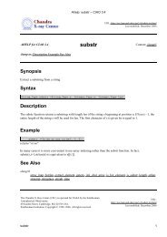
Ch<strong>and</strong>ra (formerly AXAF) X-ray Observatory <strong>and</strong> one of only two focal plane instruments. A picture of the<br />
<strong>ACIS</strong> instrument is shown in Figure 1 . In this view, the X-rays would be imaged by the X-ray mirrors, located<br />
far above the instrument, <strong>and</strong> directed downwards into the detector housing, where the CCD imaging chips are<br />
located. The <strong>ACIS</strong> <strong>door</strong> is shown in the open position in the picture. Due to the presence of a fragile optical<br />
blocking filter over the CCD's <strong>and</strong> the need for extreme cleanliness, the <strong>ACIS</strong> focal plane must be kept in an<br />
evacuated detector housing <strong>and</strong> launched under vacuum. The blocking filter essentially "blocks" any visible or<br />
ultraviolet light from entering <strong>ACIS</strong>'s aperture. Acoustic loading during the launch environment due to presence<br />
of air in the detector housing would destroy the delicate filters. The <strong>ACIS</strong> <strong>door</strong> seals the detector housing<br />
during ground operations leading up to launch. STARSYSTM paraffin (wax) actuators are used as components<br />
in a rotary actuator, to open <strong>and</strong> close the <strong>door</strong> for ground testing <strong>and</strong> on-orbit operations.<br />
The <strong>ACIS</strong> <strong>door</strong> mechanism, designed <strong>and</strong> built by Lockheed-Martin Co., was fully qualified <strong>and</strong> life tested (on<br />
an engineering model) <strong>and</strong> the flight unit had been actuated at least 23 times during component testing <strong>and</strong><br />
during system assembly <strong>and</strong> test operations. However, during the final Ch<strong>and</strong>ra Observatory level<br />
thermal/vacuum test at TRW, the <strong>door</strong> failed to open when comm<strong>and</strong>ed to do so. This <strong>failure</strong> occurred in June<br />
of 1998, at a time when the Ch<strong>and</strong>ra launch was scheduled for early CY 1999. A similar <strong>failure</strong> of the <strong>door</strong> to<br />
open on-orbit would eliminate the use of the <strong>ACIS</strong> instrument <strong>and</strong> thereby greatly degrade mission science<br />
capabilities.<br />
Needless to say, this <strong>failure</strong> at such a critical time in the Ch<strong>and</strong>ra Integration <strong>and</strong> Test cycle was extremely<br />
distressing <strong>and</strong> generated an immediate, overwhelming <strong>and</strong> ultimately successful response from a combined<br />
team of NASA-MSFC, contractor <strong>and</strong> independent review team person ne112.<br />
* The work at Optical Research Associates was performed under ADF contract 97-6135.<br />
** The work at Lockheed-Martin was performed under MIT contract SC-A-I 24624.<br />
*** This work was supported at SAO by NASA Ch<strong>and</strong>ra contract NAS8-39073.<br />
Optomechanical Engineering 2000, Mark A. Kahan, Editor,<br />
Proceedings of SPIE Vol. 4198 (2001) © 2001 SPIE · 0277-786X/01/$15.00<br />
Downloaded from SPIE Digital Library on 09 Sep 2010 to 128.103.149.52. Terms of Use: http://spiedl.org/terms
Figure 1 <strong>ACIS</strong> Instrument<br />
Downloaded from SPIE Digital Library on 09 Sep 2010 to 128.103.149.52. Terms of Use: http://spiedl.org/terms<br />
Proc. SPIE Vol. 4198 187
188<br />
Design Requirements<br />
<strong>ACIS</strong> Door Mechanism Design<br />
The design of the <strong>ACIS</strong> Detector Assembly was performed by Lockheed-Martin Astronautics under contract to<br />
MIT (contract # SC-A-124624), who in turn was under contract to NASA-MSFC for the <strong>ACIS</strong> Instrument.<br />
Design work started in 1994 with a prototype unit built prior to Preliminary Design Review (PDR). A<br />
qualification unit was built <strong>and</strong> tested in early 1995 with the flight build <strong>and</strong> test starting in early 1996. An<br />
Engineering Unit was also built <strong>and</strong> was delivered to MIT in early 1995. There were many requirements<br />
which contributed to the final design of the <strong>ACIS</strong> Detector Assembly Door Mechanism. The key <strong>ACIS</strong> <strong>door</strong><br />
requirements are listed below:<br />
I . Design Life 253 Cycles<br />
2. Operating Temperature Range<br />
-60°C to +45°C (Qualification)<br />
3. Flight Operating Temperature<br />
4. Survival Temperature Range<br />
20°C<br />
-76°C to +45°C<br />
5. Operating/non-operating Pressure 800 TORR to 0 TORR<br />
6. Operating Voltage Range<br />
24 Volts DC to 36 Volts DC<br />
7. Actuator Mm. Operating Torque > 5.1 Nm (45 ln-lbs)<br />
8. Actuator Mm. Stall Torque > 6.8 Nm (60 In-Ibs)<br />
9. On-orbit Operation<br />
10. Ground Operation<br />
One open cycle<br />
< 100 Cycles<br />
I I . Cleanliness Requirements Class IOOA <strong>and</strong> meet the Requirements of<br />
MSFC-SPEC-1238 <strong>and</strong> MIL-SPEC-1443<br />
12. Internal Vacuum Up to one atm Pressure difference Across Door<br />
13. Seal Capability < I Torr leakage per Day<br />
Contamination control was a significant design driver for the <strong>door</strong> mechanism assembly <strong>and</strong> so parting<br />
compounds were not utilized <strong>and</strong> materials <strong>and</strong> components were selected which were known to be<br />
compatible with these requirements. The requirement for an internal vacuum (in the detector housing) for all<br />
ground processing <strong>and</strong> launch environments, combined with the very low allowable leak rate for such a small<br />
instrument volume, dem<strong>and</strong>ed a nearly perfect hermetic <strong>door</strong> seal. An unlubricated Viton ® 0-ring was<br />
chosen as the sealing material because of its vacuum compatibility <strong>and</strong> low outgassing properties. The torque<br />
requirements for the <strong>door</strong> actuator were derived from some early development tests which showed a<br />
requirement for at least 2.3 Nm (20 in-Ibs) of torque capability from the actuator when using a dry Viton 0-ring.<br />
Actuator trade studies performed early in the PDR design phase resulted in a decision to proceed with a<br />
Rotary Paraffin Actuator built by STARSYS Research to drive the <strong>door</strong> mechanism open <strong>and</strong> closed. This<br />
actuator (Part # HL4570B), based on a design from a previous NASA program, had redundant built-in limit<br />
switches <strong>and</strong> heaters with a positive latch at both extremes of travel. The minimum stall torque capability for<br />
this actuator was 6.8 Nm (60 in-Ibs), which was a factor of 3 greater than required.<br />
Door Mechanism Actuator <strong>and</strong> Linkaqe<br />
The rotary actuator uses two linear paraffin actuators, one for each rotational direction. Upon actuation,<br />
heaters inside a cartridge warm the internal paraffin. As the paraffin changes phase at around 70°C its volume<br />
increase forces a steel pin outward; this linear travel is converted into rotary motion of the output shaft <strong>and</strong><br />
coupled <strong>ACIS</strong> torsion driveshaft. The driveshaft <strong>and</strong> a folding two-bar linkage rotate the <strong>door</strong> approximately<br />
92 degrees <strong>and</strong> out of the field of view upon opening; in the other direction the linkage is driven to a nearly<br />
straightened locking position when the <strong>door</strong> is closed. The linkage contains an adjustable turnbuckle, set to<br />
provide a calibrated force against the Viton 0-ring. This force, determined through development testing,<br />
provides adequate sealing for evacuation of the instrument without additional applied forces. A "swing link"<br />
supporting the <strong>door</strong> hinge axis allows the <strong>door</strong> to seat fully on the 0-ring so that 0-ring compression is uniform<br />
upon preload <strong>and</strong> evacuation. An internal shear disk in each actuator prevents excessive pressure inside the<br />
actuator from causing a catastrophic <strong>failure</strong> of the paraffin actuator cartridge & protects the other components<br />
in the device from damage. However, a shear disk rupture does render the actuator permanently disabled.<br />
Figure 1 shows the <strong>ACIS</strong> <strong>door</strong> mechanism in the open position, with the access cover removed <strong>and</strong> the<br />
Proc. SPIE Vol. 4198<br />
Downloaded from SPIE Digital Library on 09 Sep 2010 to 128.103.149.52. Terms of Use: http://spiedl.org/terms
Door Mechanism Actuator <strong>and</strong> Linkage, Concluded<br />
STARSYS actuator on the right side of the photograph. The linear actuators are the cartridges extending from<br />
the top <strong>and</strong> bottom of the rotary actuator case.<br />
Actuator Torque Requirement<br />
The output torque required from the <strong>door</strong> actuator was almost entirely driven by the expected stiction that<br />
could develop in the 0-ring <strong>door</strong> seal. A cross-section of the mechanism is shown in Figure 2 <strong>and</strong> shows the<br />
open <strong>and</strong> closed <strong>door</strong> configurations. The two bar linkage applies around 222 N (50 lbf) of force (1.8 Nm or<br />
16 in-lbs) output torque from the rotary actuator) to the 0-ring seal when in the straightened position. This<br />
force is required to compress the 0-ring sufficiently so that the detector assembly can be evacuated. The<br />
mechanism itself consists of the aluminum <strong>door</strong>, dry Torlon ® bushings in all rotating joints, titanium/aluminum<br />
linkages, a titanium collimator, aluminum seal retainer <strong>and</strong> the 15-5ph stainless steel linkage driveshaft. The<br />
slip-fit Torlon bushings all have redundant moving interfaces which would nominally still allow rotation if one of<br />
Collimator<br />
0-ring Seal<br />
Seal Retainer<br />
Figure 2 - <strong>ACIS</strong> Door Mechanism<br />
Downloaded from SPIE Digital Library on 09 Sep 2010 to 128.103.149.52. Terms of Use: http://spiedl.org/terms<br />
Proc. SPIE Vol. 4198 189
190<br />
Actuator Torque Requirement, Concluded<br />
the surfaces were to bind. Running torque for the mechanism was very low, even in IG environments, since<br />
the <strong>door</strong> weighs only about 0.1 1 kgm (025 Ibs). The total running torque for the drive train was only around<br />
0.5 Nm (4.5 in-Ibs), which was mostly the frictional <strong>and</strong> spring losses inside the rotary actuator. The frictional<br />
losses in the Torlon bushings were minimal. Analysis <strong>and</strong> testing showed that there was not an issue with<br />
clearance changes that could result in any binding of mechanism components, even at the most extreme<br />
temperatures. Additionally (post-<strong>failure</strong>), the mechanical advantages at all joints were re-computed allowing for<br />
worst case angular positions (as loose tolerances can sometimes lead to unfavorable piece-part mechanical<br />
positions). This analysis showed no positions resulting in abnormal forces or restraints.<br />
Design Redundancy<br />
As is the case with most mechanisms or structures, the <strong>door</strong> mechanism drive train components connecting<br />
the rotary actuator to the <strong>door</strong> (driveshaft, linkages, etc.) were not redundant. Rotation joints in all linkages<br />
were intended to be single fault tolerant due to the inclusion of floating Torlon bushings. Adding a second<br />
rotary actuator would have significantly complicated the mechanism. The paraffin actuators themselves<br />
contained dual sealing 0-rings <strong>and</strong> redundant heaters. The rotary actuator also contained redundant limit<br />
switches. Return springs inside the rotary actuator were designed to low operating stress levels to avoid<br />
redundancy concerns. During the design phase, a single paraffin actuator with redundant heaters was<br />
deemed to be adequate for a one-time on-orbit actuation requirement. These actuators had significant flight<br />
heritage with extremely high reliability, <strong>and</strong> required only 28 volt input power to one of the redundant heaters to<br />
perform as designed. All of the electronics required to power the actuators were fully redundant <strong>and</strong> met the<br />
single fault tolerance requirement.<br />
Paraffin actuator shear disk rupture from high internal pressure was considered a potential single point <strong>failure</strong><br />
resulting in loss of mission. During operation, the actuator reaches a temperature considerably above the<br />
paraffin melting point. If the case temperature becomes too high before heater shutoff, internal pressure is<br />
relieved by shear disk rupture. STARSYS research data showed a disk rupture threshold temperature of<br />
154°C; the design team concluded that a shut-off of 135°C left acceptable margin for <strong>door</strong> operation, based on<br />
our development testing. To protect against <strong>failure</strong>, redundant temperature sensors were installed onto the<br />
actuator case <strong>and</strong> were monitored autonomously by the <strong>ACIS</strong> Power Supply <strong>and</strong> Mechanism Controller<br />
(PSMC). Power was removed if the actuator ever reached 133-135°C. The subject of shear disk rupture will<br />
be discussed in more detail later in the paper.<br />
Qualification Testinq<br />
Pre-Flight Testing<br />
Pre-flight testing was performed per NASA procedures to fully qualify the mechanism for flight. These tests<br />
included a 253 cycle thermal/vacuum mechanism life test on a special life-test unit (CAMSIM), 0-ring stiction<br />
tests, acoustic tests, <strong>and</strong> r<strong>and</strong>om vibration tests. Initially it was felt that there were no significant issues that<br />
were not addressed in the final flight design for the <strong>door</strong> mechanism. One of the minor problems addressed<br />
was the burn-out of one of the life-cycle test heater elements. The root cause of this <strong>failure</strong> was a process<br />
change in a Minco heater that led to a delamination of the heater <strong>and</strong> subsequent burn-out as paraffin worked<br />
its way into the heater <strong>and</strong> fatigued the element. For flight, new heaters were fabricated with the original<br />
process <strong>and</strong> were re-qualified <strong>and</strong> life-cycle tested. A second problem occurred during the life-cycle test due<br />
to I C affects <strong>and</strong> rapid cycling of the mechanism <strong>and</strong> paraffin actuators. Convection inside the hot wax (only<br />
present in I G) resulted in a non-uniform re-freezing of the paraffin as it passed through the phase-change<br />
temperature. Since the paraffin froze at the bottom of the actuator first, the actuator output pin was prevented<br />
from fully retracting. This problem was addressed by procedural changes, a new retraction spring which had a<br />
higher spring constant, <strong>and</strong> an additional limit switch capability which would alert operators if the shaft was not<br />
fully retracted after a close cycle. There was a procedure in place, which never had to be used, to re-set the<br />
actuator should this problem repeat. These qualification tests showed that the mechanism was ready for flight<br />
build with no major design changes.<br />
Proc. SPIE Vol. 4198<br />
Downloaded from SPIE Digital Library on 09 Sep 2010 to 128.103.149.52. Terms of Use: http://spiedl.org/terms
Flight Unit Testing<br />
The flight unit Detector Assembly <strong>door</strong> was opened <strong>and</strong> closed at Lockheed-Martin at least 12 times as part of<br />
the component level Protoflight Test program under various test conditions prior to delivery to MIT. Testing<br />
included pre <strong>and</strong> post environmental exposure performance tests, r<strong>and</strong>om vibration tests, <strong>and</strong> thermal vacuum<br />
tests. The flight unit Detector Assembly was delivered to MIT in early 1997 <strong>and</strong> the flight focal plane <strong>and</strong><br />
optical blocking filters were installed in April of 1997. The <strong>door</strong> was cycled open <strong>and</strong> close I I more times in<br />
system level testing as described below.<br />
An <strong>ACIS</strong> system level Thermal Vacuum test of all of the flight hardware was conducted at MIT Lincoln Labs.<br />
The <strong>door</strong> was cycled two times as part of the long <strong>and</strong> short form functional testing of all <strong>ACIS</strong> hardware, at<br />
hot <strong>and</strong> cold temperature extremes, with nominal results. At the completion of this test, the integrated <strong>ACIS</strong><br />
was delivered to MSFC for an additional one month calibration test in the MSFC X-Ray Calibration Facility<br />
(XRCF) thermal/vacuum chamber. During X-ray calibration, several additional <strong>door</strong> operations cycles were<br />
performed under flight-like operating conditions with nominal performance. After calibration activities were<br />
complete, the unit was vibration tested as part of the final acceptance test by MSFC. Pre <strong>and</strong> post test<br />
mechanism performance, which included <strong>door</strong> cycling, was nominal, thus adding four more <strong>door</strong> open/close<br />
cycles. The integrated <strong>ACIS</strong> was then shipped to Ball Aerospace in Boulder for integration onto the Integrated<br />
Science Instrument Module (ISIM). The Detector Assembly was kept under vacuum for 5 months until the<br />
ISIM was fully integrated. ISIM level thermal/vacuum testing started in October 1997. During these tests the<br />
<strong>door</strong> was opened <strong>and</strong> closed two more times under flight-like conditions. One additional successful <strong>door</strong><br />
opening occurred at ambient temperature <strong>and</strong> pressure in January of 1998. The ISIM was then shipped to<br />
TRW for integration onto the Ch<strong>and</strong>ra telescope. Periodic pump downs of the <strong>ACIS</strong> Detector kept the internal<br />
pressure between 0 <strong>and</strong> 10 torr for all system integration <strong>and</strong> test activities (including system Acoustic test).<br />
Related Testiq<br />
Another STARSYS HL4570B rotary actuator (same model as for <strong>door</strong>) was used in the <strong>ACIS</strong> Large Vent Valve<br />
mechanism. A <strong>failure</strong> of this actuator occurred during the <strong>ACIS</strong> system thermal vacuum test at MIT Lincoln<br />
Labs in April of 1997. This <strong>failure</strong> was due to an operator error which caused both the open <strong>and</strong> close<br />
actuators to be powered simultaneously. Under this condition, one of the shear disks ruptured <strong>and</strong> required<br />
the removal <strong>and</strong> replacement of the Large Vent Valve rotary actuator with a flight spare actuator. Corrective<br />
action was to follow procedures to prevent simultaneous powering of open <strong>and</strong> close actuators. The large<br />
vent valve was cycled hundreds of times during test <strong>and</strong> integration <strong>and</strong> was never an issue before or after this<br />
event. However, this <strong>failure</strong> on the large vent valve pointed to a potential weakness in the actuator design. As<br />
discussed earlier, disk rupture will normally occur at a case temperature of about 154°C, <strong>and</strong> the PSMC will<br />
cut-off power when the actuator temperature reaches about 135°C. However, it was discovered that this<br />
154°C rupture temperature was based on a linear actuator in which the output pin is allowed to extend<br />
normally to full extension. Therefore, the rotary actuator must operate with stall torques less than 6.8 Nm<br />
(60 In-lbs) on the rotary output shaft. if the output pin is restrained from extending, then there is no additional<br />
volume for the paraffin to exp<strong>and</strong> into <strong>and</strong> the shear disk will rupture at a much lower temperature if power is<br />
not removed promptly. Thus, in the case of a restrained actuator, the temperature sensors do not provide<br />
protection from rupture except at end-of-stroke.<br />
As it turns out, instead of a constant temperature shut-off point, each paraffin actuator could be protected by a<br />
variable shut-off temperature dependent on the amount of linear extension of its output shaft (transformed into<br />
rotary actuator shaft rotation). At zero degrees of rotation for the rotary actuator mechanism, the shut-off<br />
temperature should have been around 90°C rising to 150°C at full rotation or end-of-stroke. However, since a<br />
normal operation of the <strong>door</strong> or large vent valve would result in an actuator temperature of I 05-1 1 0°C, we<br />
could not simply lower the shut-off temperature without affecting the ability to operate normally. It was also too<br />
late in the program to re-design the electronics to provide a variable shut-off temperature. It was evident,<br />
however, that in the case of a bound actuator shaft early in the stroke, we would not achieve our goal of<br />
opening the <strong>door</strong>. This potential new protection would have allowed us to try opening the <strong>door</strong> many times<br />
Downloaded from SPIE Digital Library on 09 Sep 2010 to 128.103.149.52. Terms of Use: http://spiedl.org/terms<br />
Proc. SPIE Vol. 4198 191
192<br />
Related Testing, Concluded<br />
rather than just once. The decision not to implement this protection was based on our high confidence n our<br />
ability to open the <strong>door</strong>, since we had never observed a stiction torque above 2.3 Nm (20 in-lbs) in over<br />
3 years of testing.<br />
To summarize the component <strong>and</strong> system level testing: the <strong>ACIS</strong> flight unit <strong>door</strong> was successfully cycled at<br />
least 23 times prior to the opening attempt at TRW under various operating temperatures <strong>and</strong> pressures. The<br />
<strong>ACIS</strong> team had confidence in the <strong>door</strong> mechanism performance for system level thermal vacuum test <strong>and</strong> for<br />
flight. There had been no anomaly in any of the previous <strong>door</strong> opening attempts. In fact, closing the <strong>door</strong> had<br />
always been of greater concern since the <strong>door</strong> was closed against a frozen (stiff) 0-ring several times during<br />
these tests. Measured paraffin actuator case temperatures were always higher when closing against a frozen<br />
0-ring, but the unit was qualified to perform under these conditions so it was never an issue.<br />
Door Opening Failure<br />
Door Opening Failure in System Thermal/Vacuum Test<br />
The fully integrated Ch<strong>and</strong>ra X-ray Observatory was subjected to over one month of thermal/vacuum testing at<br />
TRW (Ch<strong>and</strong>ra prime contractor). The final test planned for this period was a stray light test, in which the<br />
<strong>ACIS</strong> <strong>door</strong> would be opened <strong>and</strong> the <strong>ACIS</strong> used as a sensor to measure stray light levels within the telescope<br />
(lamp banks simulating the sun were installed in the TN chamber). Test conditions prior to the stray light test<br />
were nominal for the telescope, with the <strong>ACIS</strong> running at cold temperatures as would be normal for<br />
observations in flight. Since there had been several past <strong>door</strong> openings with <strong>ACIS</strong> cold <strong>and</strong> a warm-up would<br />
have taken extra time, it was decided to open the <strong>door</strong> in the cold condition. At the time, there was no<br />
objection from anyone on this point.<br />
The <strong>ACIS</strong> <strong>door</strong> opening procedure was run at 5am PDT on June 18, 1998, but the <strong>door</strong> did not open. The<br />
information available at the time was as follows: 1) Door Open Actuator exceeded its power shut-off<br />
temperature at 133°C with autonomous removal of power by the <strong>ACIS</strong> electronics (PSMC), 2) using X-ray<br />
measurements from a <strong>door</strong> mounted calibration source, it was determined that little to no motion of the <strong>door</strong><br />
had occurred, 3) STARSYS actuator limit switch operation indicated less than 20 degrees of rotation had<br />
occurred, 4) ice had been observed on external surfaces of the Observatory, indicating the presence of at<br />
least some water in the TN chamber, 5) the <strong>ACIS</strong> <strong>door</strong> <strong>and</strong> camera body were at —-60°C, <strong>and</strong> 6) the<br />
STARSYS Actuator was at -42°C at the start of the procedure.<br />
Initially Suspected Failure Modes<br />
Post-test Failure Recovery <strong>and</strong> Analysis<br />
As is usual in such cases, a small "tiger" team was formed to determine an immediate course of action. Even<br />
at this early stage, the team believed there was a high probability that the <strong>ACIS</strong> would have to be removed<br />
from the Observatory. A full stall of the mechanism with no <strong>door</strong> movement would more than likely have<br />
ruptured the shear disk inside the Paraffin Actuator based on experience with the Large Vent Valve<br />
Mechanism. A fault tree was created to help determine possible causes of the anomaly. The final form of the<br />
fault tree is shown in Figure 3. The first three (non italicized) items were those which were initially considered.<br />
Proc. SPIE Vol. 4198<br />
Downloaded from SPIE Digital Library on 09 Sep 2010 to 128.103.149.52. Terms of Use: http://spiedl.org/terms
Initially Suspected Failure Modes, Concluded<br />
A. Door/Seal Retainer Bound<br />
. Cold weld<br />
. Ice<br />
. SealAdhesion<br />
- Electrostatic<br />
- Djffusion<br />
- van der Waals<br />
- ChemicalBonding<br />
B. Rotary ActuatorBound<br />
I Parts Bound<br />
. Mismatched parts<br />
. Contamination<br />
C. Paraffin Actuator Bound or Failed<br />
. Heater failed<br />
S Wax leak<br />
. Start low temp<br />
. Low lube<br />
D. Rotary Actuator Shear Disk Previously Ruptured<br />
E. Test Procedure not followed<br />
F. Retarding Torque > 6.8Nm (60 in-lbs.)<br />
. Over-center<br />
. Seal Separation<br />
G. Linkages Bound<br />
. CTE Mismatch<br />
. Bushing/Linkage bending<br />
. Ice<br />
. Contamination<br />
Figure 3 - <strong>ACIS</strong> Door Failure Fault Tree<br />
Ideally, the team would have liked to see the unit left undisturbed to prevent the loss of information that could<br />
ultimately lead to determination of the <strong>failure</strong> mode. However, the MIT <strong>and</strong> Lockheed-Martin team concluded<br />
that there was too great a risk of damage to the focal plane <strong>and</strong> OBFs from contamination if the <strong>door</strong> were not<br />
fully closed prior to re-pressurization of the chamber. The <strong>door</strong> provides a nearly hermetic seal which would<br />
protect the focal plane <strong>and</strong> OBF's from contamination as the shrouds <strong>and</strong> spacecraft were warmed up <strong>and</strong> the<br />
chamber re-pressurized.<br />
Recovery from Failure in ThermalNacuum Test<br />
The decision was made to warm the detector assembly <strong>and</strong> <strong>door</strong> to 25°C using heaters that were designed for<br />
baking off contamination on-orbit. To protect the instrument <strong>and</strong> get the <strong>door</strong> closed, the open actuator had to<br />
be heated to soften the paraffin. With a warm open actuator, there was a higher probability that the close<br />
actuator could re-set the mechanism <strong>and</strong> latch the <strong>door</strong> closed again. The procedure was performed at 7pm<br />
PDT without success. Neither the open nor the close limit switches changed state, <strong>and</strong> the close actuator<br />
went over-temperature at 133°C as the PSMC autonomously removed power. A nominal opening or closing<br />
would normally result in an actuator temperature of around 105°C at limit switch shutoff. Now the question<br />
was whether or not the <strong>door</strong> was sufficiently sealed to allow for chamber re-pressurization. As dry nitrogen<br />
was bled into the chamber, the differential pressure transducers on the detector assembly quickly confirmed<br />
that the <strong>door</strong> was sealed, since a vacuum was measured within the detector housing. The focal plane <strong>and</strong><br />
OBF were in a safe condition, since one atmosphere of pressure differential provides about 500 pounds of<br />
Downloaded from SPIE Digital Library on 09 Sep 2010 to 128.103.149.52. Terms of Use: http://spiedl.org/terms<br />
Proc. SPIE Vol. 4198 193
194<br />
Recovery from Failure in ThermalNacuum Test, Concluded<br />
closing force on the <strong>door</strong>. Therefore once the <strong>door</strong> sealed, a positive latch was not necessary <strong>and</strong> the<br />
instrument could be h<strong>and</strong>led safely without the fear of damage to the focal plane <strong>and</strong> OBFs.<br />
During the next several days Ch<strong>and</strong>ra was removed from the chamber, the ISIM was removed from the optical<br />
bench <strong>and</strong> partially disassembled, then the <strong>ACIS</strong> was removed for shipment back to Lockheed-Martin. Initial<br />
external inspections at TRW looked normal except that the <strong>door</strong> did appear to have metal to metal contact with<br />
the seal retainer. This metal-to-metal contact could support the cold welding hypothesis but later inspections<br />
<strong>and</strong> testing would discount this <strong>failure</strong> mode. The <strong>ACIS</strong> detector was then shipped back to Lockheed-Martin<br />
where inspections <strong>and</strong> disassembly could occur in a class 100 clean room.<br />
Initial Inspections at Lockheed-Martin<br />
Failure <strong>investigation</strong> efforts centered on closing branches of the fault tree shown in Figure 3. Initial inspections<br />
of the <strong>door</strong> mechanism at Lockheed-Martin did not reveal the cause of the <strong>failure</strong>. All linkages appeared to be<br />
free <strong>and</strong> the two bar link was slightly over-center, which explained why the <strong>door</strong> was able to seal. It appeared<br />
that the <strong>door</strong> was metal to metal with the seal retainer, but until the detector was re-pressurized, we would not<br />
know if the <strong>door</strong> <strong>and</strong> seal were bound to one another. Since there was still a vacuum inside the detector, as<br />
measured with the Vacuum Ground Support Equipment (VGSE), we elected to remove the STARSYS actuator<br />
prior to detector housing re-pressurization, so that it could be inspected independently of the rest of the<br />
mechanism.<br />
Door Seal/Retainer Bound (For the Non-Italicized Fault Tree Item A)<br />
Since cold welding of the gold plated <strong>door</strong> to the aluminum seal retainer was a possible <strong>failure</strong> mode, extreme<br />
care was taken as the detector assembly was re-pressurized. Dial indicators were mounted above the <strong>door</strong> to<br />
measure movement of the <strong>door</strong> as dry nitrogen was allowed back into the camera body. The <strong>door</strong> slowly rose<br />
off of the seal retainer as the internal pressure was equalized to the ambient pressure in the clean room. The<br />
0-ring was still compliant <strong>and</strong> relaxed as the external pressure was removed from the <strong>door</strong>. Cold welding<br />
<strong>and</strong>/or galling was ruled out both because the 0-ring <strong>and</strong> its gl<strong>and</strong> had been sized to preclude line-to-line<br />
metal contact after a compressive set, <strong>and</strong> because the as-built 0-ring had enough spring force to push the<br />
<strong>door</strong> away from the seal retainer. Close inspection revealed no signs of cold welding, metal burnishing, or<br />
metal-to-metal oxide/contaminant adhesion. This also would have been the case when the TRW thermal<br />
vacuum chamber was initially evacuated since the pressure differential across the <strong>door</strong> would been reduced in<br />
a similar manner.<br />
With the differential pressure equalized, the <strong>door</strong> could be opened <strong>and</strong> running torque <strong>and</strong> seal adhesion could<br />
be measured. Using a torque wrench to drive the <strong>door</strong> open, the seal adhesion plus running torque was<br />
measured to be 2.6 Nm (23 in-Ibs) which was near the expected value. Seal adhesions had never been<br />
measured above 2.3 Nm (20 in-Ibs) <strong>and</strong> with a running torque of around 0.5 Nm (4 in-Ibs), the seal adhesion<br />
was 2.2 Nm (1 9 in-Ibs). The full capability of the STARSYS actuator as measured in subsequent testing, was<br />
around 10.2 Nm (90 in-Ibs) which gave a factor of safety of over 4 above what was measured. With running<br />
torque within normal specifications, no problems were found with the mechanism. Further disassembly <strong>and</strong><br />
inspections showed all dimensions for bushings <strong>and</strong> other components to be within specifications at room<br />
temperature. No binding or interference was found which could have contributed to the <strong>failure</strong>. Additional<br />
testing on the Torlon® bushings showed that the coefficient of thermal expansion was as expected <strong>and</strong> that<br />
analytically there were no concerns with the mechanism binding at low temperatures.<br />
The over-center torque on the <strong>door</strong> mechanism was also found to be within specifications at about I .9 Nm<br />
(17 in-Ibs). Since this flight mechanism was set up in an over-center condition, due to normal rotational <strong>and</strong><br />
machining tolerances, there was concern that if the over-center torque was too high then it could have<br />
combined with another <strong>failure</strong> mode to result in excessive retarding torque. This was shown not to be the case<br />
with testing on other engineering units even for an incompressible 0-ring. Conservatively, the flight unit was<br />
re-assembled with the mechanism adjusted in a slightly under-center condition by building a new adapter<br />
bracket.<br />
Proc. SPIE Vol. 4198<br />
Downloaded from SPIE Digital Library on 09 Sep 2010 to 128.103.149.52. Terms of Use: http://spiedl.org/terms
STARSYS Actuator Inspection <strong>and</strong> Test( Fault Tree Items B <strong>and</strong> C)<br />
Failure of the STARSYS rotary actuator was one of the <strong>failure</strong> modes identified on the fault tree. X-ray<br />
inspection of the unit did not show any anomaly. As was expected, the open actuator shear disk had ruptured<br />
due to excessive pressures inside the actuator. The open actuator output shaft was slightly extended which<br />
explained why the latch <strong>and</strong> limit switches were not engaged. Some drive shaft rotation was also observed in<br />
the X-rays of the actuator. There was no evidence of any foreign material or debris that could have jammed<br />
the mechanism. The open actuator cartridge was then removed from the actuator assembly. As the actuator<br />
was removed, the latches <strong>and</strong> limit switches fell into place. The slightly extended output shaft, which was<br />
frozen in the paraffin, had prevented the actuator from re-setting completely. The shear disk looked like a<br />
normally ruptured disk with no signs of any material weakness. Material properties were measured for the<br />
shear disk <strong>and</strong> were as expected. There were no signs of wax leakage <strong>and</strong> internal inspections of the wax<br />
cartridge were nominal. Force measurements were made to determine the running torque for the rotary<br />
mechanism <strong>and</strong> were nominal at both room temperature <strong>and</strong> at —45°C.<br />
Prior to total disassembly, the close actuator cartridge was removed <strong>and</strong> installed onto the open actuator side<br />
of the rotary mechanism assembly. At STARSYS, the unit was tested to <strong>failure</strong> with a full stall to characterize<br />
the performance of the actuator <strong>and</strong> shear disk under these conditions. This full stall test, performed at -45°C,<br />
simulated the condition where the <strong>door</strong> mechanism did not rotate <strong>and</strong> all bushings <strong>and</strong> linkages were frozen<br />
solid. The temperature profiles were similar to those which were measured at the time of the <strong>failure</strong> up until<br />
the actuator reached a temperature of around 129°C, at which time the shear disk ruptured. This is slightly<br />
lower than the estimated <strong>failure</strong> temperature of 132°C at TRW, but would be expected with this more severe<br />
test condition. The <strong>door</strong> mechanism linkages <strong>and</strong> torsion shaft would have allowed more rotation of the rotary<br />
actuator <strong>and</strong> thus a higher temperature at shear disk rupture. It is interesting to note that both shear disks<br />
were nearly protected since the PSMC shut-off temperature was set at I 33-1 35°C. The peak torque at shear<br />
disk function was 10.4 Nm (92 in-Ibs) vs. the 6.8 Nm (60 in-lbf) specification. Material testing showed that both<br />
the open <strong>and</strong> close shear disks were similar in thickness <strong>and</strong> shear properties, so it is likely that the STARSYS<br />
rotary actuator output was around 10.2 Nm (90 in-Ibs) at the time of the <strong>failure</strong> at TRW. Complete<br />
disassembly <strong>and</strong> inspection of the mechanism <strong>and</strong> actuators did not reveal a problem. Nothing was<br />
obstructing the mechanism <strong>and</strong> the only discrepancy was the ruptured shear disk. This closed out numerous<br />
branches on the fault tree since everything appeared <strong>and</strong> functioned nominally.<br />
The shear disk rupture point varies linearly depending on the amount of extension of the actuator linear output<br />
shaft, which can be anywhere from 0 to 19 mm. At 0 mm of linear extension, test data showed the actuator<br />
would reach an equivalent pressure to achieve 6.8 Nm (60 in-lbf) on the output shaft at around 90°C. The<br />
rupture temperature would be higher at an equivalent output torque of I 0.2 Nm (90 in-Ibs). For an extension of<br />
19 mm, the shear disk would rupture at an estimated 154°C. Subsequent discussions will show that we<br />
believe the flight unit shear disk ruptured at around I 32°C which also supports the evidence that the <strong>door</strong><br />
mechanism had rotated 20-25 degrees (5.7 mm of linear extension) at the time of <strong>failure</strong> <strong>and</strong> was not locked<br />
up. The clearances in the bushings <strong>and</strong> the windup in the mechanism components could allow the actuator<br />
linear output pin to extend as much as 5.7 mm even with a stuck <strong>door</strong>.<br />
Failure Investigation Team<br />
NASMndustry Team Formation <strong>and</strong> Failure Investigation Approach<br />
The small team of Lockheed-Martin, NASA-MSFC <strong>and</strong> STARSYS personnel as discussed above initiated <strong>door</strong><br />
mechanism <strong>failure</strong> diagnostics. Their goal was to determine the cause of the <strong>failure</strong>, fix the problem, <strong>and</strong> then<br />
return the <strong>ACIS</strong> detector to flight configuration so that it could be reinstalled on Ch<strong>and</strong>ra <strong>and</strong> still meet the<br />
(then projected) January 1999 launch schedule. This team was initially given two weeks to complete these<br />
activities, based on the (optimistic) assumption that the <strong>failure</strong> mechanism would be easily identified <strong>and</strong><br />
rectified. As it eventually became clear that the <strong>failure</strong> was not going to be quickly resolved, NASA-MSFC<br />
formed a larger <strong>ACIS</strong> Door "Tiger" team which included members from NASA-MSFC, selected members the<br />
Ch<strong>and</strong>ra External Independent Readiness Review (EIRR) Board (from Optical Research Associates & the<br />
Aerospace Corporation), MIT, Lockheed-Martin, STARSYS, TRW <strong>and</strong> SAO. The team's function was to<br />
oversee <strong>and</strong> facilitate the ongoing <strong>ACIS</strong> <strong>door</strong> <strong>failure</strong> <strong>investigation</strong> <strong>and</strong> the decision making process. In the end,<br />
the team was to operate for almost one year, as circumstances dictated, with weekly telecons <strong>and</strong> meetings as<br />
necessary.<br />
Downloaded from SPIE Digital Library on 09 Sep 2010 to 128.103.149.52. Terms of Use: http://spiedl.org/terms<br />
Proc. SPIE Vol. 4198 195
196<br />
Failure Investigation Team, Concluded<br />
The situation at the time the larger team was formed, in early July 1998, was not a promising one. As<br />
described above, initial work by the smaller team had ruled out many of the proposed <strong>failure</strong> mechanisms.<br />
Also, program schedule pressure was large, even though the launch date had been slipped to mid-summer<br />
1999 due to other factors. The exp<strong>and</strong>ed team, along with senior NASA <strong>and</strong> program management, decided to<br />
pursue parallel paths of off-line <strong>failure</strong> <strong>investigation</strong> along with the re-build <strong>and</strong> re-test of the <strong>ACIS</strong> detector <strong>and</strong><br />
then re-integration with the Ch<strong>and</strong>ra Observatory. It was believed that the re-test effort would also supply<br />
valuable data to the <strong>failure</strong> <strong>investigation</strong> team. As a further backup possibility, NASA-MSFC even developed<br />
an alternate actuator that could have been substituted into <strong>ACIS</strong> should subsequent problems with the above<br />
paths occur downstream closer to launch.<br />
With more resources available now, many activities could proceed in parallel, even though the primary activity<br />
remained at Lockheed-Martin. These activities included the expansion of the fault tree to include a more<br />
detailed examination of the italicized items some of which were not initially considered, further <strong>investigation</strong><br />
into the issue of ice formation, more detailed <strong>investigation</strong>s into the stiction properties of Viton, a search of the<br />
prior test data to look for a possible inadvertent powering of the <strong>door</strong> actuator, development of a detailed finite<br />
element model of the <strong>door</strong> mechanism <strong>and</strong> 0-ring to provide additional design verification <strong>and</strong>, of course, the<br />
re-build of the flight <strong>ACIS</strong> detector for a re-test at TRW in August of I 998.<br />
Further Failure Investigations (Italicized Items, SectionA, Figure 3), Changes, <strong>and</strong> Launch Liens<br />
The exp<strong>and</strong>ed review team briefly reinvestigated a large number of fault tree branches that had been<br />
previously closed by analysis, test, <strong>and</strong> inspection. Possibilities reviewed included considerations that slow<br />
voltage ramp-ups in testing could have inadvertently produced a condition that might burst an actuator, as well<br />
as microscopic effects of ice/water, &/or Viton cold-flow. Additional tests <strong>and</strong> analyses were conducted in each<br />
of these areas, <strong>and</strong> selected design <strong>and</strong> operational changes were made to address each open fault tree<br />
branch. Mitigation schemes were implemented <strong>and</strong> verified by tests &/or FEM techniques including: (a) the<br />
use of a controlled energy slug <strong>and</strong> potentiometer to allow multiple opportunities to open the <strong>door</strong> on-orbit<br />
(reducing any paraffin actuator shear disk operational risk), (b) the previously noted elimination of "overcenter"<br />
torque so as provide additional margin, <strong>and</strong> (c) use of <strong>door</strong> grounding to eliminate concerns relative to<br />
any stiction induced by electrostatic forces. Although a few KV were initially computed (given an Ion 55 source<br />
which was attached to the <strong>door</strong> for later use in on-station telescope calibrations), this value was later reduced<br />
to low levels as both further analysis <strong>and</strong> testing showed that the small gap at the seal interface can't support<br />
a significant level of charge build up. Regardless, the grounding strap was added for safety.<br />
It was believed that a warm <strong>door</strong> opening on-orbit would close all open fault tree branches, but a launch<br />
constraint was imposed requiring a successful KSC open/close cycle. Further, an additional defacto launch<br />
constraint was imposed which required successful Engineering Unit testing using flight-like timelines for <strong>door</strong><br />
closure. Here, the Engineering Unit (EU) testing incorporated both expected vibration & acoustic loading as<br />
well as use of selected on-station heating as part of a thermal '<strong>mitigation</strong> sequence" (this sequence will be<br />
discussed shortly). It was decided that the launch would be scrubbed if EU <strong>door</strong> opening required over 45 in-lb<br />
of torque (laboratory testing showed I 9 in-lb to be a nominal stiction value, with worst-case test data of 44 in-lb<br />
achieved only once at -60°C after 28 hours). Recall that 90 in-lb was needed to cause the actuator to fail, so in<br />
constraining torques to 45 in-lb there would still be about 2X torque margin. While assessing a value to use as<br />
an EU toque limit, we also linearly added all the identified non-seal-surface-based stiction sources, <strong>and</strong><br />
determined that only 55 in-lb of seal-based resistance might be sufficient to fail an actuator.<br />
The cracking of the <strong>door</strong> seal at KSC would reset the stiction clock, but this was not without some risk of its<br />
own. Though the contamination effects of a KSC opening were evaluated <strong>and</strong> found to be acceptable, there<br />
existed the possibility that a never-seen ambient-only open <strong>failure</strong> might occur given the potential of van der<br />
Waals forces. (Recall how difficult it is to pull apart two mating microscope slides, especially with an<br />
intermediate thin film of water. Further, try <strong>and</strong> remove an ice-cube from a countertop after the cube has<br />
begun to melt. This type of stiction ties to the electrical polarization induced by surface particles; forces go<br />
Proc. SPIE Vol. 4198<br />
Downloaded from SPIE Digital Library on 09 Sep 2010 to 128.103.149.52. Terms of Use: http://spiedl.org/terms
Further Failure Investigations (Italicized Items, Section A, Figure 3), Changes, <strong>and</strong> Launch Liens, Continued<br />
inversely as the seventh power of intermolecular distances involved.) Since ambient open forces were<br />
generally 2X those in vacuum, there seemed to be reason for suspicion. Also, since van der Waals forces can<br />
climb to 20-30 Ksi <strong>and</strong> the <strong>door</strong>-seal is approximately 20 inches in overall length by 0.1 inch in compressedcross-section,<br />
stiction forces had the potential to overcome the available torque, even if only 1/20% of the<br />
mating surfaces were involved. The Team recognized that should a water-film based stiction actually occur at<br />
KSC, the case that the <strong>door</strong> would open on-station, despite the closure of fault tree branches, would be further<br />
weakened, <strong>and</strong> the launch might well be jeopardized. Moreover, any such ambient <strong>failure</strong> would be hard to<br />
"mitigate" at KSC as adequately dehumidifying the area would be quite difficult. Also, only small thermal<br />
changes could be introduced at ambient conditions, <strong>and</strong> small changes were determined to be insufficient to<br />
provide effective stiction <strong>mitigation</strong>. The Team decided to accept this risk, <strong>and</strong> press-on.<br />
In parallel to firming-up KSC plans, the team developed procedural <strong>details</strong> & a flow-chart for a warm on-station<br />
opening that incorporated torque relationships as a function of time <strong>and</strong> temperature, <strong>and</strong> which accounted for<br />
all possible hardware tolerances (including issues of timing errors, temperature read-out anomalies, etc.).<br />
Also, a simulator (the CAMSIM) was used to check cold torque's, <strong>and</strong> this unit was configured to act as a<br />
Flight Unit Shadow. The CAMSIM would then be able to act as a realistic test-specimen should on-station<br />
difficulty eventually be encountered.<br />
Transfer function calculations <strong>and</strong> tolerancing of all linkages were reworked, <strong>and</strong> all build-books were<br />
reviewed. No toleranced positions yielded sufficiently high torque to produce <strong>failure</strong>, even given the potential<br />
mechanical interferences in worst-case error stack-ups. These stack-ups accounted for temperature changes<br />
under differential expansion (Torlon/H20 testing gave 36-37 ppm/°C matching vendor data of 30 ppm/°C), as<br />
well as relative humidity swelling <strong>and</strong> changes in the Torlon bushings (where creep effects were also<br />
measured). A detailed review of displacements Vs angles Vs joint mechanical advantages confirmed that<br />
iced/bound joints give insufficient restraint to cause a <strong>failure</strong> ( 2 in-lbs of change). This was further confirmed<br />
by additional CAMSIM iced-Up testing. This work, taken together with our analysis, helped to eliminate linkage<br />
binding as the root cause of the <strong>failure</strong>.<br />
Our new on-orbit operating procedures utilized the application of pulsed power to help prevent<br />
functioning/bursting of the shear disk. This allowed repeated attempts to be made to open the <strong>door</strong>. This new<br />
approach was verified on the Flight Unit (8 times), <strong>and</strong> actuator temperature/torque performance was fully<br />
characterized so we would know what to expect on-station. Also, telemetry rates were increased during <strong>door</strong><br />
operation so as to allow for real-time interaction <strong>and</strong> possible intervention during flight <strong>door</strong> opening. Flight<br />
opening temperatures were set at ambient levels, but <strong>mitigation</strong> plans were included as a formal part of our<br />
<strong>door</strong> opening procedure. Here the plan was to rapidly thermally cycle the seal interface from 20-25°C to -60°C<br />
<strong>and</strong> back to 20-25°C, as ground testing showed that this type of cycling resulted in a 90% reduction in 0-ring<br />
stiction.<br />
The <strong>ACIS</strong> instrument operates with the detector housing at -60 °C. Bakeout heaters are supplied to<br />
temporarily raise the detector housing temperature to 25 °C in order to remove molecular contamination<br />
collected by the cold surfaces in the detector housing. Under normal conditions the radiators can cool the<br />
<strong>ACIS</strong> detector housing from 25 °C to -60 °C in about I I hours. In contrast the bakeout heaters can raise the<br />
detector housing temperature to 25 °C in about 4 hours. For the sake of <strong>mitigation</strong> these temperature slopes<br />
constitute a rapid temperature cycle. On orbit, the bakeout heaters were on when the <strong>ACIS</strong> <strong>door</strong> was opened,<br />
raising the <strong>door</strong> seal to 20-25 °C. Should the <strong>door</strong> have failed to open, the heaters would have been turned<br />
off <strong>and</strong> the temperature of the <strong>ACIS</strong> detector housing allowed to fall to about -60 °C. Immediately after<br />
reaching low temperature, the heaters would then have been turned back on <strong>and</strong> the detector housing warmed<br />
back up to about 25 °C. After reaching high temperature, the <strong>door</strong> would then have again be comm<strong>and</strong>ed to<br />
open, as experiment has shown that for adhesions formed at 25 °C, this technique reduces residual adhesions<br />
to insignificant levels.<br />
Downloaded from SPIE Digital Library on 09 Sep 2010 to 128.103.149.52. Terms of Use: http://spiedl.org/terms<br />
Proc. SPIE Vol. 4198 197
198<br />
Further Failure Investigations (Italicized Items, Section A, Figure 3), Changes, <strong>and</strong> Launch Liens, Continued<br />
As work on the opening sequence proceeded, testing <strong>and</strong> forensics continued. Black "lines" were seen on the<br />
parted sealing surfaces. Surface reflectivity shifts due to changes in the stociometry of the gold surface coating<br />
were initially suspected, but forced 0-ring extractions <strong>and</strong> lR Spectroscopy resulted in identification of the<br />
potential that a compressed baked Viton seal (two 3-4day 40+ °C cycles) could give rise to small amounts<br />
(
Further Failure Investigations (Italicized Items, Section A, Figure3), Changes, <strong>and</strong> Launch Liens, Concluded<br />
opposing sealing surface, the two surfaces would move laterally relative to each other by an amount greater<br />
than the average size of any surface pits that might be frozen in place. Allowing for Vitons cold elasticity <strong>and</strong><br />
strength, it was speculated that, given this limited FEM analysis, the net effect of these thermally induced axial<br />
<strong>and</strong> lateral motions would result in a pulling apart <strong>and</strong> shearing of any bond formed at the interface by Viton or<br />
water ice. This proved true even with cold Viton peel forces & strength up by I .5X to 3X, based on limited<br />
testing.<br />
0-ring Finite Element Model<br />
assumed fixed, relative to gl<strong>and</strong>,<br />
at sides <strong>and</strong> bottom;<br />
<strong>door</strong> effects excluded<br />
0-ring Motion Based on AT = -80 °C<br />
Lateral Motion X-Dir = 2 im w/r/t <strong>door</strong><br />
Vertical Motion Z-Dir = 8 pm w/r/t <strong>door</strong><br />
0-ring Motion Based on Temp Gradient of<br />
20°C between Door<strong>and</strong> Gl<strong>and</strong><br />
Lateral Motion X-Dir = 35 im<br />
Combo of Effects May Break Stiction<br />
Pit Size: 10 tm wide; 2 im deep<br />
8 im Z-Disp due to Soak is > 2pm<br />
35 pm X-Disp due to Gradient is > 10 pm<br />
Figure 4 AXAF Door O..ring Motions<br />
Relative 0-Ring Z -Disp; AT = -80 °C<br />
Beyond these factors, our Team also looked in detail at the specific fabrication processes used to make<br />
Ch<strong>and</strong>ras 2-162 Viton 747-75 seals. In preparing Viton it is usually advisable to avoid alcohol wipes, though<br />
Viton s less damaged than many epoxies (e g Kapton has been rumored to experience apparent changes n<br />
surface texture) We also measured the material's diffusion <strong>and</strong> off-gassing rates (boiled 0-rings absorbed<br />
3 8% water by weight Vs 0 38% for st<strong>and</strong>ard unboiled 0-rings) Viton (Vinylidene Flouride &<br />
Hexafluoropropylene Copolymer in a formulation referred to as V747-75) contains carbon black high activity<br />
Magnesium Oxide (3%) & Calcium Hydroxide Hydrated MgO has the formula Mg(OH)2 <strong>and</strong> there are some<br />
Indications that MgO & Mg(OH)2 also stick to metals (especially the later) Ch<strong>and</strong>ra s seals were injection<br />
molded which results in a higher molecular orientation than compression molding It also adds mold<br />
contaminants <strong>and</strong> release agents into the mix. However, testing showed all these factors to be unlikely as root<br />
causes of the <strong>failure</strong>.<br />
We also surveyed other polymer bonding models Vs temperature in development at the Argonne National<br />
Laboratory, Georgia Tech., U. Cal. Santa Barbara, Pitt., Berkeley, Unitel Mixte de Recherches CNRS - Elf<br />
Atochem (France), <strong>and</strong> others, as well as tribiology studies on friction <strong>and</strong> wear. However, no additional<br />
potential root causes surfaced as a result of these reviews.<br />
Downloaded from SPIE Digital Library on 09 Sep 2010 to 128.103.149.52. Terms of Use: http://spiedl.org/terms<br />
Proc. SPIE Vol. 4198 199
200<br />
<strong>ACIS</strong> Detector Rebuild <strong>and</strong> Re-Test<br />
In the rebuild of the <strong>ACIS</strong> detector, much attention was given to possible ways to gain information on<br />
performance of the <strong>door</strong> actuator. Instrumentation to monitor <strong>door</strong> mechanism performance was added prior<br />
to the re-test which started in August, 1998. This instrumentation included non-flight strain gages to measure<br />
actuator output torque, a potentiometer on the torsion shaft (flight) <strong>and</strong> an additional temperature sensor to be<br />
used for "pulsed heating" of the paraffin actuator. This pulsed heating technique, in conjunction with<br />
potentiometer readings, would prevent the heating of the paraffin actuator so as to rupture the shear disk.<br />
Finally, a rapid warm-up <strong>and</strong> cool-down procedure was developed <strong>and</strong> demonstrated to reduce 0-ring stiction<br />
(one of the possible causes of the <strong>failure</strong>) in case the pulsed heating technique did not initially open the <strong>door</strong>.<br />
The re-test of the <strong>ACIS</strong> <strong>door</strong> mechanism (August/September 1 998) was intended to re-qualify the <strong>door</strong><br />
mechanism under flight conditions. It was decided to re-test the <strong>ACIS</strong> <strong>door</strong> as mounted to the ISIM only, not<br />
the entire Observatory. This would greatly simplify the testing <strong>and</strong> also allow work on the Observatory to<br />
proceed in parallel with <strong>ACIS</strong>/ISIM re-test. A key decision of the <strong>failure</strong> <strong>investigation</strong> team <strong>and</strong> program<br />
management was that the test would take place with the detector housing warm, as was planned for the onorbit<br />
opening. This would eliminate any issues of ice during the re-test, but since water itself was an issue due<br />
to possible van der Waals forces, water was to be injected into the thermal/vacuum chamber to simulate the<br />
outgassing of the complete Observatory's composite materials. Some team members would have preferred to<br />
duplicate all test conditions at the time of <strong>failure</strong> (including detector temperature), but there was concern that<br />
another <strong>failure</strong>, even under non-flight conditions, would jeopardize program schedule.<br />
The re-built <strong>ACIS</strong> detector was shipped back from Lockheed-Martin to TRW in early August 1998, <strong>and</strong> was<br />
then integrated onto the ISIM. The lSlM with both Ch<strong>and</strong>ra focal plane science instruments (<strong>ACIS</strong> <strong>and</strong> HRC)<br />
was then moved into the TRW thermal vacuum chamber. The subsequent test then simulated as closely as<br />
possible the projected on-orbit <strong>door</strong> opening scenario. The predicted temperature profile was closely followed.<br />
The <strong>ACIS</strong> detector housing was kept cold until about 14 days into the test, at which time the <strong>door</strong> was opened.<br />
Prior to <strong>door</strong> opening, the detector housing temperature was raised to 25°C using the <strong>ACIS</strong> bake-out heaters.<br />
The <strong>door</strong> was opened (<strong>and</strong> then closed) a total of five times during the lSlM re-test, all using the pulsed<br />
heating technique. The first three openings. were done with a bus voltage of 28 volts <strong>and</strong> the last two at<br />
32 volts. The <strong>door</strong> angle potentiometer <strong>and</strong> driveshaft strain gages were monitored during these openings. All<br />
of the data from these openings was nominal. This successful re-qualification of the <strong>ACIS</strong> <strong>door</strong> mechanism<br />
allowed the program to proceed towards launch, but the fact that the cause of the earlier <strong>failure</strong> was still not<br />
exactly known was troubling to everyone. The <strong>ACIS</strong> <strong>failure</strong> <strong>investigation</strong> team would work for many more<br />
months, still attempting to discover the root cause of the earlier <strong>failure</strong>.<br />
It should also be noted that there were additional <strong>door</strong> openings in an ambient condition scheduled <strong>and</strong><br />
executed to gain confidence in the <strong>door</strong> opening mechanism prior to launch. This was accomplished through<br />
the use of the VGSE to re-pressurize the <strong>ACIS</strong> detector housing cavity with nitrogen to equalize the pressure<br />
prior to opening. This was not originally planned due to the risk of contamination entering the cavity <strong>and</strong> of<br />
inadvertently damaging the thin spectral filters. However, a more detailed look showed that if procedures were<br />
carefully followed, these risks were small enough to be acceptable, given the circumstances.<br />
Ongoing Failure Investigations<br />
The exp<strong>and</strong>ed <strong>ACIS</strong> <strong>door</strong> fault tree is shown in Figure 3. This tree evolved over the course of the <strong>investigation</strong><br />
<strong>and</strong> guided our efforts to identify the <strong>failure</strong> mechanism. As mentioned above, early post-<strong>failure</strong> inspections<br />
<strong>and</strong> tests addressed some of the branches of the tree.<br />
Pre-ruptured Shear Disk (Fault tree Item D)<br />
One possible <strong>failure</strong> mechanism which had not yet been ruled out, was an accidental activation of the open<br />
actuator under ambient pressure conditions prior to the TRW test. This would have taken place after the last<br />
opening at Ball (January 98) <strong>and</strong> before the opening attempt during Observatory ThermalNacuum testing.<br />
With a vacuum inside the detector, the shear disk would have ruptured if the open actuator were powered<br />
Proc. SPIE Vol. 4198<br />
Downloaded from SPIE Digital Library on 09 Sep 2010 to 128.103.149.52. Terms of Use: http://spiedl.org/terms
Pre-ruptured Shear Disk (Fault tree Item D), Continued<br />
when the Observatory was in an ambient environment, since the mechanism does not have enough torque<br />
margin to overcome one atmosphere of pressure against the <strong>door</strong>. Ch<strong>and</strong>ra flight telemetry was monitored<br />
anytime that Ch<strong>and</strong>ra or the ISIM were powered up. An <strong>investigation</strong> of the available telemetry data showed<br />
no time at which the actuator temperature had exceeded ambient. However, a potential <strong>failure</strong> mode was<br />
discovered when it was determined that when the spacecraft voltage was ramped up slowly, the <strong>ACIS</strong><br />
mechanism controller could power up without receiving a comm<strong>and</strong> to do so. The team was able to duplicate<br />
this condition on the <strong>ACIS</strong> test hardware <strong>and</strong> was able to show that the mechanism could have been powered<br />
up inadvertently. However, the temperature profile <strong>and</strong> limit switch actuation measured at TRW during the<br />
<strong>door</strong> open <strong>failure</strong> did not match the characteristics which would be obtained for a pre-ruptured shear disk.<br />
(When the actuator is stroked, the expansion of the paraffin gives an additional tell-tale; it produces a 2 °C to<br />
3 °C thermal inflection point in valve time-temperature traces.) This conclusion is based on extensive testing<br />
with non-flight hardware <strong>and</strong> also the actual flight actuator used in the failed opening attempt.<br />
As part of this work the timing accuracy's of all comm<strong>and</strong>s were also reexamined (data logging within major &<br />
minor data frames), <strong>and</strong> this too was cleared as a potential <strong>failure</strong> source. Comm<strong>and</strong>s go to the controller at<br />
the start of major frames (within 3 - 4 seconds), while both <strong>door</strong> actuator <strong>and</strong> valve temperatures are recorded<br />
later, in minor frames. This type of signal timing initially made the <strong>door</strong> actuator appear to rise in temperature<br />
before data-tell-tales showed that the actuation comm<strong>and</strong> was actually sent.<br />
Figure 5 shows a typical torque curve. The strain gauge amplifiers were zeroed prior to opening even though<br />
this measurement contains significant zero offset. This offset is caused by the strain in the shaft required to<br />
maintain the 50 pound preload on the closed <strong>door</strong>. When the actuator unlatches (at -85 seconds in Fig 5) the<br />
forces from the preload back-drive the actuator until the running torque of the actuator arrests this motion.<br />
This exhibits itself as a level portion of the curve where the linear wax actuator "catches up" to the back-driven<br />
output shaft. During this time the limit switch picks up showing that the actuator is unlatched. As the wax<br />
actuator continues its stroke what remains of the 50 pound preload is removed as shown in Figure 5 by<br />
steadily declining torque. Eventually, the preload torque is completely relieved, which removes the<br />
compression on the <strong>door</strong> linkage. At this time the linkage travels through a dead b<strong>and</strong> caused by the<br />
clearances in the various mechanical components. This too is exhibited by a second, level segment of the<br />
curve ( -1 00 seconds) <strong>and</strong> represents the true zero torque value at the shaft. As rotation continues, the<br />
linkage begins to pull on the <strong>door</strong> <strong>and</strong> the shaft torque curve in Figure 5 continues to decline. At this point the<br />
linkage is in transition from compression to tension <strong>and</strong> so represents a change of sign for the shaft torque.<br />
From this point on the torque measured is the torque caused by the adhesive forces between the 0-ring <strong>and</strong><br />
the <strong>door</strong> <strong>and</strong> any small running torque caused by bearing friction <strong>and</strong> gravitational loads. As can plainly be<br />
seen this continues until the torque curve discontinuously jumps. This discontinuity has been visually<br />
correlated with <strong>door</strong> first motion on all of the tests performed. A small residual strain remains after the<br />
discontinuity <strong>and</strong> is a result of the now freely hanging <strong>door</strong> with gravity pulling it open <strong>and</strong> any residual torque<br />
in the mechanism.<br />
For the purposes of this analysis the second plateau caused by the unloading of the <strong>door</strong> mechanism is used<br />
as zero. The minimum reached just prior to the discontinuity was used as the opening torque. Thus, in the<br />
example shown in Figure 5 the opening torque is about 6.5 in-lbs.<br />
Microswitch triggering tests were also conducted (positions; effects of energy stored in the linkage, etc.).<br />
These tests showed that energy stored in the linkage can move switch positions by up to 0.05", effecting the<br />
apparent timing of critical mechanical events (the shaft rotates from I OO to 200 under 60 in-lb of torque).<br />
Downloaded from SPIE Digital Library on 09 Sep 2010 to 128.103.149.52. Terms of Use: http://spiedl.org/terms<br />
Proc. SPIE Vol. 4198 201
202<br />
Pre-ruptured Shear Disk (Fault tree Item D), Concluded<br />
U)<br />
.0<br />
C<br />
a)<br />
0<br />
2<br />
0<br />
-2<br />
-4<br />
-6<br />
-8<br />
-10<br />
-12<br />
-14<br />
-I 6<br />
-18<br />
80<br />
)-••••+••• ''+•- •••<br />
3<br />
1<br />
CAMSIM Opening Torque<br />
45.5 Hour Vacuum Compression<br />
Ice on Mechanism (Items A <strong>and</strong> G of Fault Tree)<br />
—4-— Drive Shaft Torque (in-Ibs)<br />
— Switch I<br />
witch 3<br />
Figure 5. Typical Torque Curve for Opening <strong>ACIS</strong> Door<br />
Icing of the mechanism (as opposed to the <strong>door</strong> seal itself) was thought to be a promising <strong>failure</strong> mode since<br />
the <strong>failure</strong> occurred when the <strong>door</strong> was opened cold <strong>and</strong> frost was seen on the Observatory optical bench prior<br />
to the opening <strong>failure</strong>. However, analysis showed that ice could not have caused the problem with the <strong>door</strong><br />
mechanism. At the time of the <strong>failure</strong>, several different pressure monitors inside the chamber showed the<br />
pressure to be in the 106 Torr range. At this temperature (-60°C) <strong>and</strong> pressure, the sublimation rate for<br />
water/ice is greater than the collection rate <strong>and</strong> it was unlikely that enough ice could exist on surfaces at -60°C<br />
to cause a problem. Colder surfaces at, -90°C or less, did have visible ice because the collection rate was<br />
higher than the sublimation rate. Some water/ice was probably present on mechanism components since<br />
there were increases in pressure when the heater was turned on to warm the housing to +25°C. However, the<br />
thickness of water/ice would have been angstroms <strong>and</strong> not the millimeters which would have been required to<br />
block the mechanism. A pressure increase was also observed with the on-board Ch<strong>and</strong>ra vacuum monitor<br />
when the heater was turned on. However, even small amounts of water/ice could result in increased pressure<br />
at vacuum levels of i05 to 106 Torr. The local pressure around the mechanism would have had to been an<br />
unlikely I 0 Torr in order for enough ice to collect to cause a problem. On a global basis then, the presence of<br />
ice was analytically shown to be non-credible. (However, as we have noted, locally, in a trapped interstitial<br />
space, the conditions can differ sufficiently to allow an iced-up seal to remain as a viable potential <strong>failure</strong><br />
mode.)<br />
To further investigate the water/ice <strong>failure</strong> mode, an engineering unit <strong>door</strong> mechanism was purposefully iced<br />
up by cooling it with liquid nitrogen in ambient pressure. The mechanism <strong>and</strong> STARSYS actuator were<br />
covered with ice from relative humidity condensation but the running torque increase was barely measurable.<br />
Other tests <strong>and</strong> studies were performed, but all of our test results failed to show icing as a <strong>failure</strong> mechanism.<br />
Proc. SPIE Vol. 4198<br />
I<br />
85 90 95 100 105<br />
Time (Seconds)<br />
110 115 120<br />
Downloaded from SPIE Digital Library on 09 Sep 2010 to 128.103.149.52. Terms of Use: http://spiedl.org/terms<br />
30<br />
27<br />
24<br />
21<br />
C<br />
0<br />
18 0C0<br />
I—<br />
15 . U<br />
12<br />
E<br />
9<br />
6<br />
3<br />
0
Further Commentary on 0-ring Adhesion Mechanisms<br />
During the course of this <strong>investigation</strong> various 0-ring adhesion mechanisms have been proposed as possible<br />
causes for the <strong>failure</strong>. Although none have been shown conclusively to occur under the <strong>failure</strong> conditions of<br />
the flight hardware, several remained viable possibilities. This is especially true if two or more adhesion<br />
mechanisms acted together synergistically. All possibilities focused on the properties of Viton adhering to the<br />
gold surface of the <strong>door</strong> seal under various conditions. Although this <strong>failure</strong> mode is believed to be the most<br />
probable <strong>failure</strong> mode, no test or analysis could conclusively prove that enough adhesion could have existed<br />
at TRW to prevent the <strong>door</strong> from opening. Lockheed-Martin conducted many tests with engineering hardware<br />
that duplicated the environmental conditions, but not the 7 months that existed before <strong>and</strong> during the <strong>failure</strong>.<br />
(Exponential curve-fitting of stiction values Vs time asymptote to 12.1 in-Ibs, <strong>and</strong> logarithmic fits predicted<br />
I 8.3 in-Ibs, tantalizingly close to the I 9 in-lb of torque measured when the flight <strong>door</strong> was first opened after the<br />
<strong>failure</strong>. Neither of these predicted values would create any difficulty for the <strong>ACIS</strong> actuator <strong>and</strong> mechanisms.)<br />
The team was unable to reproduce the <strong>failure</strong> under any simulated circumstance.<br />
Plans for Flight Opening<br />
An immense effort was expended to identify the <strong>failure</strong> mechanism prior to launch, but despite the best efforts<br />
of many able people, we were not able to conclusively identify the <strong>failure</strong> mechanism. In fact, it sometimes<br />
seemed as if the <strong>failure</strong> could not have occurred, but it had. As time went on <strong>and</strong> we approached the launch<br />
date without a clearly identified root cause, the team's (<strong>and</strong> program management's) approach was to<br />
eliminate or "mitigate" all possible remaining <strong>failure</strong> modes. The decision to open the <strong>door</strong> warm, which had<br />
always been the plan, would eliminate any potential issues with icing, however unlikely.<br />
Since 0-ring stiction seemed to be the most likely <strong>failure</strong> mechanism, even though it could not be proven,<br />
plans were developed to deal with it in the flight situation. First of all, it appeared that the stiction level would<br />
build over time, starting out at a low value when the <strong>door</strong> was initially closed, <strong>and</strong> reaching an asymptote at<br />
some later time. To minimize the potential stiction build-up, it was decided to open the flight <strong>door</strong> as late as<br />
possible in the integration process.<br />
Another stiction <strong>mitigation</strong> technique was developed by the Team <strong>and</strong> confirmed by Lockheed-Martin in their<br />
testing using engineering models of the <strong>door</strong> mechanism. It was determined that thermal cycling of the<br />
detector housing would lower stiction levels. Mitigation testing on the CAMSIM test unit showed that a rapid<br />
temperature cycle to 25°C would virtually eliminate any 0-ring adhesion which was present prior to the cycle.<br />
Two tests were preformed after a room temperature dwell with I atmosphere of pressure on the <strong>door</strong> for<br />
21 <strong>and</strong> 172 hours. Using a prediction based on previous 0-ring adhesion testing, one would estimate seal<br />
adhesion of 0.6 <strong>and</strong> 1.2 Nm (5.8 <strong>and</strong> 10.5 in-Ibs), respectively. After the <strong>mitigation</strong> thermal cycle (described<br />
above) was performed, only 0.1 Nm (0.7 in-Ibs) of adhesion were measured in both cases.<br />
In preparation for flight, the Ch<strong>and</strong>ra Flight Operations Team (FOT) developed a procedure which was<br />
essentially identical to the multiple-heating-cycle ground procedure, <strong>and</strong> modified the telemetry<br />
decommutation software <strong>and</strong> display pages to utilize the new information available on the <strong>door</strong> mechanism.<br />
A full end-to-end test of the new <strong>door</strong> procedure was executed on September 27, 1998 from the Ch<strong>and</strong>ra<br />
Operations Control Center in Cambridge, MA, controlling the Observatory at TRW. The ISIM was installed on<br />
the Observatory, which was in ambient conditions. The flight procedure utilized a library of comm<strong>and</strong><br />
sequences that contained the actuator heater-on comm<strong>and</strong>, a fixed time delay, <strong>and</strong> the actuator heater-off<br />
comm<strong>and</strong>. These sequences were built with time delays of 50s to 200s in 5s intervals, <strong>and</strong> additionally in<br />
250s <strong>and</strong> 300s intervals. The operator could then select the comm<strong>and</strong> sequence with an appropriate time<br />
interval based on the starting temperature of the actuator, the spacecraft bus voltage, <strong>and</strong> the results of the<br />
previous heating cycle. On September 27, 1 998 the <strong>door</strong> opened nominally in five heating cycles. The heating<br />
cycles used were of 70, 85, 1 00, 1 1 0, <strong>and</strong> 250 sec. <strong>and</strong> reached maximum actuator temperatures of<br />
61.2, 68.9, 74.1, 76.6, <strong>and</strong> 99.9°C. The spacecraft bus voltage was 31.5 V <strong>and</strong> the input voltage at the PSMC<br />
was 30.9 V.<br />
The final pre-flight <strong>door</strong> opening took place on May 10, 1999, before Ch<strong>and</strong>ra was integrated with the orbiter<br />
Columbia. The opening went smoothly, after equalizing the pressure with the VGSE, with all data perfectly<br />
nominal. The instrument was comm<strong>and</strong>ed from the <strong>ACIS</strong> EGSE at KSC. The Observatory was in ambient<br />
Downloaded from SPIE Digital Library on 09 Sep 2010 to 128.103.149.52. Terms of Use: http://spiedl.org/terms<br />
Proc. SPIE Vol. 4198 203
204<br />
Plans for Flight Opening, Concluded<br />
conditions in the Vertical Assembly Building. The <strong>door</strong> was opened with 4 heating cycles of 90, 1 00, 1 1 0, <strong>and</strong><br />
I 80 sec. duration's, <strong>and</strong> the actuator reached maximum temperatures of 63, 68, 72, <strong>and</strong> I 00 C. The<br />
spacecraft bus voltage was 30 V.<br />
On-Orbit Door Opening<br />
The Ch<strong>and</strong>ra X-ray Observatory was launched from KSC on July 23, 1999 in the orbiter Columbia. On August<br />
8, 1999 the <strong>ACIS</strong> <strong>door</strong> was opened as planned, 16 days after launch. The <strong>door</strong> opening sequence is shown in<br />
Figure 6. The same procedure was used to open the <strong>door</strong> in flight as had been used on the ground test at<br />
TRW. The only difference was the timing of the individual heating pulses. The <strong>door</strong> was opened with<br />
5 heating cycles of 90, 110, 125, 140 <strong>and</strong> 200 sec. <strong>and</strong> the actuator reached a maximum temperature of<br />
56.1, 68.9, 79.2, 87.0, <strong>and</strong> I 10.3°C. The spacecraft bus voltage was 31.0 V <strong>and</strong> the input voltage at the PSMC<br />
was 30.4 V. Actuator temperature, <strong>door</strong> angles <strong>and</strong> limit switch transitions were all as expected <strong>and</strong> are<br />
shown in the figure. With the successful <strong>door</strong> opening, the Ch<strong>and</strong>ra X-ray Observatory planned calibration<br />
observations were completed <strong>and</strong> scientific studies are now being performed as intended. The stiction<br />
<strong>mitigation</strong> technique we developed was essential to allow us to proceed through launch, but the actual stiction<br />
values seen by the Flight Unit were sufficiently low (with the KSC re-setting of our stiction-"clock") that its use<br />
was not required.<br />
ci)<br />
a)<br />
.1<br />
I<br />
120<br />
100<br />
80<br />
60<br />
40<br />
20<br />
0<br />
Proc. SPIE Vol. 4198<br />
21 22 23<br />
Time(hrs day 220)<br />
Figure 6 - On-Orbit <strong>ACIS</strong> Door Opening<br />
Downloaded from SPIE Digital Library on 09 Sep 2010 to 128.103.149.52. Terms of Use: http://spiedl.org/terms
Lessons Learned<br />
If there is one lesson to be learned, it is to always "test as you plan to fly" <strong>and</strong> not push the limits of a<br />
mechanism to facilitate schedule, logistics or to reduce other potential impacts to the test program. On-orbit, it<br />
was always planned to open the <strong>door</strong> with the camera body <strong>and</strong> 0-ring at 25 °C. During testing, if we had<br />
operated the <strong>door</strong> mechanism as planned, the <strong>door</strong> may have opened <strong>and</strong> we would not have had to deal with<br />
the long <strong>and</strong> involved <strong>failure</strong> <strong>investigation</strong>. If it had failed during test, the fault tree would have been much<br />
simpler since we would not have to deal with issues related to cold operation. One positive contribution,<br />
however, was the development of a much safer, more reliable operational procedure that ultimately would<br />
contribute to a successful <strong>door</strong> opening on-orbit.<br />
Another lesson is that either the mechanism design or operational procedure should allow for a prolonged stall<br />
condition to occur, due to possible binding or stiction, without mechanism component <strong>failure</strong>. In the <strong>ACIS</strong> <strong>door</strong><br />
application, due to the late occurrence of the <strong>failure</strong>, the program successfully adopted an operational<br />
technique to preclude a <strong>failure</strong> due to a stalled condition, <strong>and</strong> also developed a technique to remove the cause<br />
of the stall.<br />
The results of the <strong>ACIS</strong> <strong>door</strong> <strong>failure</strong> <strong>investigation</strong> ultimately were inconclusive <strong>and</strong> thus very frustrating. The<br />
specific cause of the test <strong>failure</strong> was never positively identified, although several potential causes were left<br />
open as possible. As it became clear that the specific cause might not be identified, much effort was put into<br />
"<strong>mitigation</strong> procedures". These procedures were developed to 'mitigate" or to reduce the effect of, possible<br />
<strong>failure</strong> mechanisms such as 0-ring stiction. These procedures were extensively tested on <strong>ACIS</strong> <strong>door</strong><br />
engineering models, <strong>and</strong> later on the flight unit itself.<br />
References<br />
I . Ch<strong>and</strong>ra X-Ray Observatory <strong>ACIS</strong> Failure Investigation, MSFC & Tiger Team Briefings <strong>and</strong> Final Report,<br />
18 June 1998 to 12 February 1999, Respectively.<br />
2. <strong>ACIS</strong> Door Failure Investigation <strong>and</strong> Mitigation Procedures, N. Tice, W. Podgorski <strong>and</strong><br />
P. Plucinsky, 34th Aerospace Mechanisms Symposium, 1999.<br />
3. Relation of the Equilibrium Contact Angle to Liquid <strong>and</strong> Solid Constitution, W. Zisman, US NRL,<br />
Advances in Chemistry Series, No. 43, American Chemical Society, Washington, DC, 1964,<br />
Pgs. 1-56.<br />
4. Influences ofConstitution on Adhesion, W. Zisman, lnd. Eng. Chem., Vol. 55, No. 10, 1963,<br />
Pgs. 18-38.<br />
5. Liquid-Like (Transition) Layer on Ice, H. Jellinek, Dept. of Chemistry, Clarkson College of Technology,<br />
J. Colloid. & Interface Sci., Vol. 25, 1967, Pgs. 192-205.<br />
6. Studies of Ice Adhesion, US. Naval Applied Science Laboratory, M. L<strong>and</strong>y & A. Freiberger,<br />
J. Colloid. & Interface Sci., Vol. 25, 1967, Pgs. 231-244.<br />
7. Ice Adhesion to Hydrophilic <strong>and</strong> Hydrophobic Surfaces, W. Bascom, R. Cottington, & C. Singleterry,<br />
Chemistry Division, US NRL, J. Adhesion, Vol. 1, Oct. 1969, Pgs. 246-263.<br />
8. The Friction <strong>and</strong> Creep of Polycrystalline Ice, P. Barnes, D. labor, & J. Walker, Surface Physics,<br />
Cavendish Laboratory, Cambridge, Proc. Roy. Soc. London, Vol. A342,<br />
l2Augustl97l, Pgs. 127-155.<br />
9. Elastic Properties ofAmorphous <strong>and</strong> Crystalline Ice Films, J. Hessinger, B. White, Jr., &<br />
R. PohI, Laboratory of Atomic <strong>and</strong> Solid State Physics, Cornell University, Planetary <strong>and</strong><br />
Space Science, Vol. 44. No. 9. Sept. 1996, Pgs. 937-944.<br />
I 0. Physical Chemistry of Surfaces, Third Edition, Arthur Adamson, Dept. of Chemistry, Univ. of Southern<br />
Calif., J. Wiley & Sons, Pgs. 454 & 458.<br />
I I . On Stickiness, C. Gay & L. Leibler, Physics Today, November 1 999, Pgs. 48-52.<br />
12. Astrophysics CCD Imaging Spectrometer (<strong>ACIS</strong>) Failure Investigation Report, Adhesion Mitigation<br />
Methodology Final Report, S. Anderson, Lockheed Martin Astronautics Flight Systems,<br />
28 January 1999.<br />
Downloaded from SPIE Digital Library on 09 Sep 2010 to 128.103.149.52. Terms of Use: http://spiedl.org/terms<br />
Proc. SPIE Vol. 4198 205