PANUKL Help - ITLiMS
PANUKL Help - ITLiMS PANUKL Help - ITLiMS
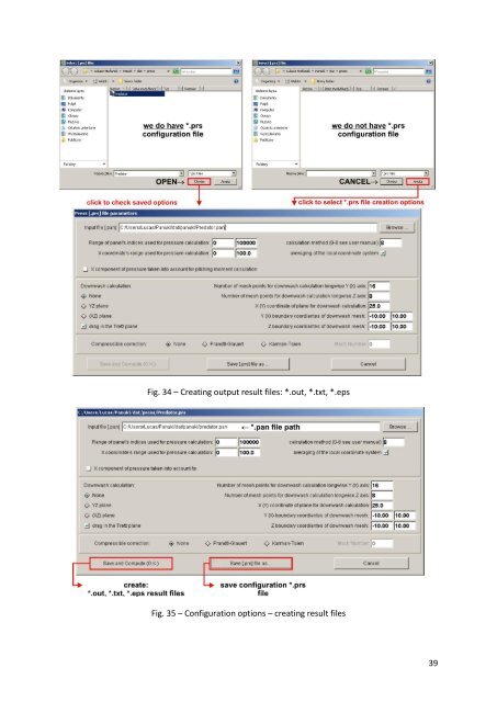
Mach Number Mach number Roll rate [rad/s] P – roll rate [rad/s] Pitch rate [rad/s] Q – pitch rate [rad/s] Yaw rate [rad/s] R – yaw rate [rad/s] Function Description Compute pressure distribution This command will run Press.exe, PANUKL application component. User will be asked to point input velocity potential distribution file (*.pan). Based on input file the output *.out, *.txt & *.eps, files will be created. The *.out file contains computed global aerodynamic coefficients results for analyzed body. The *.txt file contains computed results for pressure coefficient, velocity, source or doublet distribution etc. for each aircraft body panel. The *.eps file contains wing angle of deviation results. Option No. 1 – we do have saved on disk configuration file *.prs, Fig. 34 Run Compute pressure distribution and select saved configuration file *.prs – file contains all necessary information to create output result files – *.out, *.txt, *.eps. To open selected *.prs file click OPEN button. Configuration window will appear (Fig. 35) where one can see saved *.prs file creation options. To generate output files click Save and Compute (ok) button. Option No. 2 – we do not have saved on disk configuration file *.prs, Fig. 34 Run Compute pressure distribution and click CANCEL button when prompted for saved configuration file *.prs. The configuration window will appear (Fig. 35) where user can select options to create output files – *.out, *.txt, *.eps. To save current output files options to *.prs file click Save [*.prs] file as, to create output files click Save and Compute (ok) button. 38
Fig. 34 – Creating output result files: *.out, *.txt, *.eps Fig. 35 – Configuration options – creating result files 39
- Page 1 and 2: Version ENGV1 Warsaw, 01-04-2010 1
- Page 3 and 4: 3.3. Data flow In PANUKL during the
- Page 5 and 6: 1.1.2. Introduction The develop of
- Page 7 and 8: Fig. 1 - Approximation of the body
- Page 9 and 10: - lift force - drag force The aerod
- Page 11 and 12: 1.2.3. Main computational subprogra
- Page 13 and 14: File [name.f] - fuselage geometry -
- Page 15 and 16: File [name.ms2] - complete aircraft
- Page 17 and 18: ottom # key word „bottom” or
- Page 19 and 20: Fig. 6 - The example of „independ
- Page 21 and 22: File [name.TXT] The results for pre
- Page 23 and 24: File [name.CZY] Aerodynamic coeffic
- Page 25 and 26: Fig. 13 - Destination Folder select
- Page 27 and 28: 2.2. PANUKL installation guide in L
- Page 29 and 30: Available options in FILE menu) Fun
- Page 31 and 32: 3.1.2. DRAW menu description Availa
- Page 33 and 34: Fig. 28 - Creating grid file for cu
- Page 35 and 36: Trailing edge angle [deg] Neighbour
- Page 37: Fig. 32 - Creating *.pan file Fig.
- Page 41 and 42: Downwash calculation: Number of mes
- Page 43 and 44: Fig. 38 - External XFOIL program wi
- Page 45 and 46: Fig. 41 - Selecting result file wit
- Page 47 and 48: 3.1.6. TOOLS menu description Avail
- Page 49 and 50: Fig. 48 - Graphic representation of
- Page 51 and 52: 3.2. Computational procedure - diag
- Page 53 and 54: 3.3. Data flow In PANUKL during the
- Page 55 and 56: How it Works ? Option 1 - we do hav
- Page 57 and 58: 4.2. Creation of complex computatio
- Page 59 and 60: Step 4 Right side of the object is
- Page 61 and 62: Important notes: What we should kno
- Page 63 and 64: Main program options: Folder path f
- Page 65 and 66: 4.4. How to export geometry from UG
- Page 67 and 68: Remember: don’t insert DATUM PLAN
- Page 69 and 70: In some fuselage areas you will hav
- Page 71 and 72: Fig. 86 - Models prepared with the
Fig. 34 – Creating output result files: *.out, *.txt, *.eps<br />
Fig. 35 – Configuration options – creating result files<br />
39


