PANUKL Help - ITLiMS
PANUKL Help - ITLiMS PANUKL Help - ITLiMS
1.3. Input data 1.3.1. Input data file description File [name.prf] – wing airfoil geometry – file description # - comment line (not necessary) WING AIRFOIL FILE EXAMPLE 24 #n – number of points defining curvature lines for current airfoil (both top and bottom curvature line), Fig. 4 # top curvature line definition #bottom curvature line definition # X coordinates # Y coordinates # X coordinates # Y coordinates 0.000 0.000 0.000 0.000 0.006 0.093 0.006 -0.093 0.622 0.905 0.622 -0.905 2.233 1.655 2.233 -1.655 4.806 2.330 4.806 -2.330 8.290 2.911 8.290 -2.911 12.615 3.380 12.615 -3.380 17.693 3.722 17.693 -3.722 23.422 3.929 23.422 -3.929 29.687 4.001 29.687 -4.001 36.361 3.945 36.361 -3.945 43.311 3.776 43.311 -3.776 ... … … … Fig. 4 – Wing airfoil *.prf file definition - example 12
File [name.f] – fuselage geometry – file description # - comment line (not necessary) Number of points in one section15 FUSELAGE GEOMETRY FILE EXAMPLE Number of sections 10 #n number of defined fuselage frames/ sections Section 0 #0 first fuselage frame/ section #section def. point number # Y coordinate # Z coordinate 0.000 0.000 0.000 Section 1 #0 second fuselage frame/ section #section def. point number # Y coordinate # Z coordinate Section 2 -3.3 0.000 -0.400 -3.3 0.100 -0.390 -3.3 0.200 -0.350 -3.3 0.280 -0.280 -3.3 0.350 -0.200 -3.3 0.390 -0.100 -3.3 0.400 0.000 -3.3 0.400 0.000 -3.3 0.400 0.000 -3.3 0.390 0.100 -3.3 0.350 0.200 -3.3 0.280 0.280 -3.3 0.200 0.350 -3.3 0.100 0.390 -3.3 0.000 0.400 #section def. point number # Y coordinate # Z coordinate -2.3 0.000 -0.610 -2.3 0.160 -0.590 -2.3 0.300 -0.530 -2.3 0.430 -0.430 … … … Section 9 #(n-1) – number of the last fuselage Frome/ section #section def. point number # Y coordinate # Z coordinate 1.3 0.000 0.000 Yellow marked section def. points belong to 3 independent stringers (Fig. 5), their coordinates are the same outside the area where wing or horizontal tail penetrates fuselage. 13
- Page 1 and 2: Version ENGV1 Warsaw, 01-04-2010 1
- Page 3 and 4: 3.3. Data flow In PANUKL during the
- Page 5 and 6: 1.1.2. Introduction The develop of
- Page 7 and 8: Fig. 1 - Approximation of the body
- Page 9 and 10: - lift force - drag force The aerod
- Page 11: 1.2.3. Main computational subprogra
- Page 15 and 16: File [name.ms2] - complete aircraft
- Page 17 and 18: ottom # key word „bottom” or
- Page 19 and 20: Fig. 6 - The example of „independ
- Page 21 and 22: File [name.TXT] The results for pre
- Page 23 and 24: File [name.CZY] Aerodynamic coeffic
- Page 25 and 26: Fig. 13 - Destination Folder select
- Page 27 and 28: 2.2. PANUKL installation guide in L
- Page 29 and 30: Available options in FILE menu) Fun
- Page 31 and 32: 3.1.2. DRAW menu description Availa
- Page 33 and 34: Fig. 28 - Creating grid file for cu
- Page 35 and 36: Trailing edge angle [deg] Neighbour
- Page 37 and 38: Fig. 32 - Creating *.pan file Fig.
- Page 39 and 40: Fig. 34 - Creating output result fi
- Page 41 and 42: Downwash calculation: Number of mes
- Page 43 and 44: Fig. 38 - External XFOIL program wi
- Page 45 and 46: Fig. 41 - Selecting result file wit
- Page 47 and 48: 3.1.6. TOOLS menu description Avail
- Page 49 and 50: Fig. 48 - Graphic representation of
- Page 51 and 52: 3.2. Computational procedure - diag
- Page 53 and 54: 3.3. Data flow In PANUKL during the
- Page 55 and 56: How it Works ? Option 1 - we do hav
- Page 57 and 58: 4.2. Creation of complex computatio
- Page 59 and 60: Step 4 Right side of the object is
- Page 61 and 62: Important notes: What we should kno
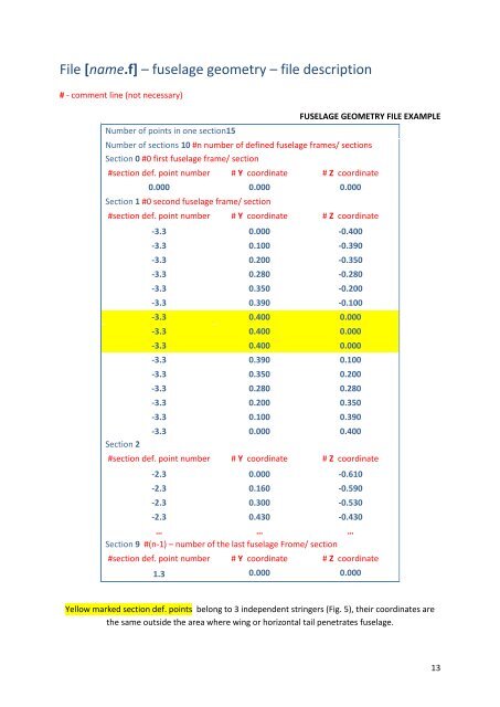
File [name.f] – fuselage geometry – file description<br />
# - comment line (not necessary)<br />
Number of points in one section15<br />
FUSELAGE GEOMETRY FILE EXAMPLE<br />
Number of sections 10 #n number of defined fuselage frames/ sections<br />
Section 0 #0 first fuselage frame/ section<br />
#section def. point number # Y coordinate # Z coordinate<br />
0.000 0.000 0.000<br />
Section 1 #0 second fuselage frame/ section<br />
#section def. point number # Y coordinate # Z coordinate<br />
Section 2<br />
-3.3 0.000 -0.400<br />
-3.3 0.100 -0.390<br />
-3.3 0.200 -0.350<br />
-3.3 0.280 -0.280<br />
-3.3 0.350 -0.200<br />
-3.3 0.390 -0.100<br />
-3.3 0.400 0.000<br />
-3.3 0.400 0.000<br />
-3.3 0.400 0.000<br />
-3.3 0.390 0.100<br />
-3.3 0.350 0.200<br />
-3.3 0.280 0.280<br />
-3.3 0.200 0.350<br />
-3.3 0.100 0.390<br />
-3.3 0.000 0.400<br />
#section def. point number # Y coordinate # Z coordinate<br />
-2.3 0.000 -0.610<br />
-2.3 0.160 -0.590<br />
-2.3 0.300 -0.530<br />
-2.3 0.430 -0.430<br />
… … …<br />
Section 9 #(n-1) – number of the last fuselage Frome/ section<br />
#section def. point number # Y coordinate # Z coordinate<br />
1.3 0.000 0.000<br />
Yellow marked section def. points belong to 3 independent stringers (Fig. 5), their coordinates are<br />
the same outside the area where wing or horizontal tail penetrates fuselage.<br />
13


